
Recommended
More Related Content
Similar to NM200E Nuclear Core Verification System
Similar to NM200E Nuclear Core Verification System (15)
Recently uploaded
Recently uploaded (20)
NM200E Nuclear Core Verification System
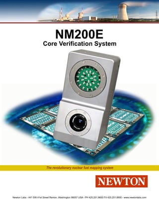
- 1. NM200E Core Verification System The revolutionary nuclear fuel mapping system Newton Labs - 441 SW 41st Street Renton, Washington 98057 USA - PH 425.251.9600 FX 425.251.8900 - www.newtonlabs.com
- 2. Fulfilling a Need of the Nuclear Power Industry T he NM200E Core Verifica�on System is a revolu�onary technology that enables nuclear plant operators to accurately measure the posi- �ons of all fuel assemblies in a PWR reactor at the end of an outage. Construction and Materials: • The 9 lb. (4 kg) mapping head is Developed by Newton Labs in partner- In addi�on to accuracy, the NM200E 6061T6 aluminum hard-anodized ship with a major U.S. nuclear u�lity, the features a considerably rapid mapping �me • All fasteners and connectors are NM200E produces a precise global map of of two hours or less. A major factor for the 316 Stainless Steel. • Windows are made of high- fuel assembly s-hole posi�ons, including speed of the system, beyond so�ware pro- strength fused silica any degree of misalignment or top nozzle cessing �me, is an expanded field of view. • O-rings and gaskets are Buna-N rota�on and compares them with the ideal The NM200E system combines rugged, rubber and the cable jacket is LLDPE posi�ons established by plant engineers. industrial-grade hardware and electron- polyurethane. The accuracy of the NM200E is derived ics into a design that can both tolerate • The mapping head is designed and built to tolerate radia�on and from sophis�cated, Newton-developed radia�on exposure and handle the rigors of has performed well in the presence so�ware that compensate for the visually deployment during reactor outages. of Gamma radia�on levels of 5kR. distor�ng thermal turbulence and use the • The head is configured with alter- core baffles as posi�onal references. nate moun�ng points on most faces and is waterproof to a depth of 150 �. (45.72 m). NM200E Core Verification System Components: • The NM200E mapping head encloses a high-resolu�on video camera and a high-intensity LED ring array • The console unit contains the camera control unit, a rack-mounted PC, flat panel screen and wireless keyboard with trackball • The communica�ons cable is a standard length of 150 �. (45.72 m); lengths up to 300 �. (91.44 m) may be special ordered • Newton Labs core mapping so�ware • Components are housed in two, high impact airline-transportable luggage cases Newton Labs - 441 SW 41st Street Renton, Washington 98057 USA - PH 425.251.9600 FX 425.251.8900 - www.newtonlabs.com
- 3. Core Verification Combining Accuracy and Speed The Core Mapping Sequence: 1. The camera, mounted in its false fuel as- sembly, is gripped by the refuel mast. 2. The bridge operator commands the bridge to a predefined loca�on (i.e. fuel assembly N3) above the core. 3. The live video feed from the camera is displayed with a graphical alignment over- lay generated from the fuel layout map. This reconfirms that the system is alive, ready and producing the an�cipated im- ages (clear, level, square, etc.). 4. The operator indicates the system can begin mapping into the user interface. 5. The NM200E takes a series of images at the first loca�on that are processed using mul�ple techniques to accurately generate baffle and s-hole posi�ons for all fuel as- semblies in the field of view. 6. A global es�mate of each s-hole loca- NM200E software overlays a graphic of identified s-hole locations atop the real-time image. The Core �on (in mm/inches) is generated, using the Map (upper right) displays the current mapping location and the in or out-of-tolerance status of each detected baffle posi�on as a fixed reference fuel assembly, compared to the ideal. In this example, the fuel assemblies in this scan area are all within tolerance point. The so�ware iden�fies not only non- standard gaps, but also fuel assemblies that are rotated or shi�ed within the core. 7. The core map updates automa�cally, sav- ing all data to redundant storage devices. 8. The camera head is moved to the next loca�on, iden�fied on the user interface, maintaining a par�ally overlapping field of view (FOV). The procedure is repeated. 9. The so�ware combines and correlates the s-hole loca�ons iden�fied in all previ- ous FOVs with the current FOV to account for changes in camera rota�on and align- ment, refining s-hole loca�on es�mates. 10. Upon reaching a baffle opposite the star�ng point, the camera is shi�ed later- ally, maintaining some FOV overlap. The process is repeated in the reverse direc�on, con�nuing in a zig-zag pa�ern un�l all fuel assemblies have been seen by the system. 11. The core map display on screen visually indicates the final results of each mapped fuel assembly in one of three colors: When selected, the Results Map (left) displays a graphical core representation identifying the location Green - for within tolerance of found s-holes in relation to their ideal locations. The Results Tab (lower right) lists the deltas of all Yellow - for within tolerance, but located s-holes. greater than the specified gap Red - for out-of-tolerance Newton Labs - 441 SW 41st Street Renton, Washington 98057 USA - PH 425.251.9600 FX 425.251.8900 - www.newtonlabs.com
- 4. Designed and Built for the Rigors of PWR Outages Newton Labs - 441 SW 41st Street Renton, Washington 98057 USA - PH 425.251.9600 FX 425.251.8900 - www.newtonlabs.com
- 5. NM200E Technical Specifications Item Control Unit Camera Head Height 14.75 in. (374.65 mm) 4.5 in. (114.30 mm) Width 26.75 in. (679.45 mm) 4.60 in. (116.73 mm) Length 27.50 in. (698.5 mm) 8.64 in. (219.34 mm) Weight (in air) 84.5 lbs. (38.3 kg) 9 lbs. (4 kg) Weight (in water) --- 2 lbs. (1 k) (plus cable weight) Construction Metal electronics rack suspended on eight shock Machined from solid billet of absorbers within a molded, high-impact, airline- 6061T6 aluminum stock transportable case Cable LLDPE polyurethane jacket, gel filled - 150 ft. --- (45.72 m) (other lengths available) Cable weight - 150 ft. (in air) 23.6 lbs. (10.7 kg) --- Video camera --- High Resolution Monochrome LED ring array --- 4,800 lumens Fittings & retainers --- 300 series stainless steel Windows --- Fused silica or optical glass Mounting attachments --- Four grouped 1/4-20 UNC threaded mounting holes on four sides of case (Metric threads available) Operating system Ubuntu Linux 11.04 --- Output ports Ethernet, USB, DVI, VGA & HDMI --- Operating temperature 40° to 110° F (5° to 43° C) 86° to 95° F (30° to 35° C ) in reactor 100% duty cycle Storage temperature 0° to 125° F (-18° to 52° C) 0° to 160° F (- 18° to 71° C) Power input voltage/current 100 to 240 VAC 50 to 60 cycle Powered by control unit Data storage Internal solid state & USB stick data --- Output formats XML, CSV, PNG & PDF --- Watertight depth rating --- 150 ft. (45.72 m) Comparison to Video Micrometer Procedure • The NM200E offers substan�al • The accuracy of a video micrometer advantages over the legacy video mi- scan is highly dependent on operator crometer process in terms of accuracy experience and camera orienta�on, and mapping �me. processes that are handled automa�cally • The video micrometer method and consistently by the NM200E. merely gauges the rela�ve nozzle gap • The video micrometer field of vision varia�ons, limi�ng an operator to is no more than one and a half fuel only being able to infer the posi�on of nozzles wide, resul�ng in a consider- s-holes. ably longer mapping �me, compared to the NM200E, which registers an area of three by four nozzles and can completely map a core in less than two hours. Newton Labs - 441 SW 41st Street Renton, Washington 98057 USA - PH 425.251.9600 FX 425.251.8900 - www.newtonlabs.com
- 6. Information on Newton Labs N ewton Labs is a privately held developer and manufacturer of machine vision, robot- ics and op�cal automa�on. A spin-out from the Massachuse�s Ins�tute of Technol- ogy (MIT), the company has for more than 18 years developed and marketed high per- formance, computer-driven automa�on for industrial processes. Newton’s products are designed to allow the quality, efficiency and cost effec�veness of computer technology to replace the human element in virtually every industry. Newton Labs has deployed more than 20,000 machine vision, robo�c and automa�on systems worldwide. Offices and manufacturing facilities of Newton A Related Nuclear Industry Product from Newton Labs Labs - Renton, Washington, USA A n industry “sister product” is the _NM200UW Nuclear Underwater Laser Scanner, a landmark technology developed by Newton Labs in partnership with a major U.S. nuclear u�lity. The scanner output is a point cloud so detailed, that when u�lized with industry standard, 3-D so�ware, a fully measur- able CAD model can be generated. The capability of the NM200UW to provide precise, reliable and efficient di- mensioning of as-built features, as well as to track cycle-to-cycle degrada�on, is im- portant to nuclear u�lity operators, who un�l now have relied heavily on indirect, inexact measurement techniques. NM200UW Nuclear Underwater Laser Scanner Left: The point cloud output of an underwater retaining bolt scanned by a NM200UW within a PWR Right: The measurable CAD file rendering of the same scanned bolt. For more informa�on about this product, contact Newton Labs: lasersales@newtonlabs.com or call 425-251-9600 Revised 102611 Newton Labs - 441 SW 41st Street Renton, Washington 98057 USA - PH 425.251.9600 FX 425.251.8900 - www.newtonlabs.com