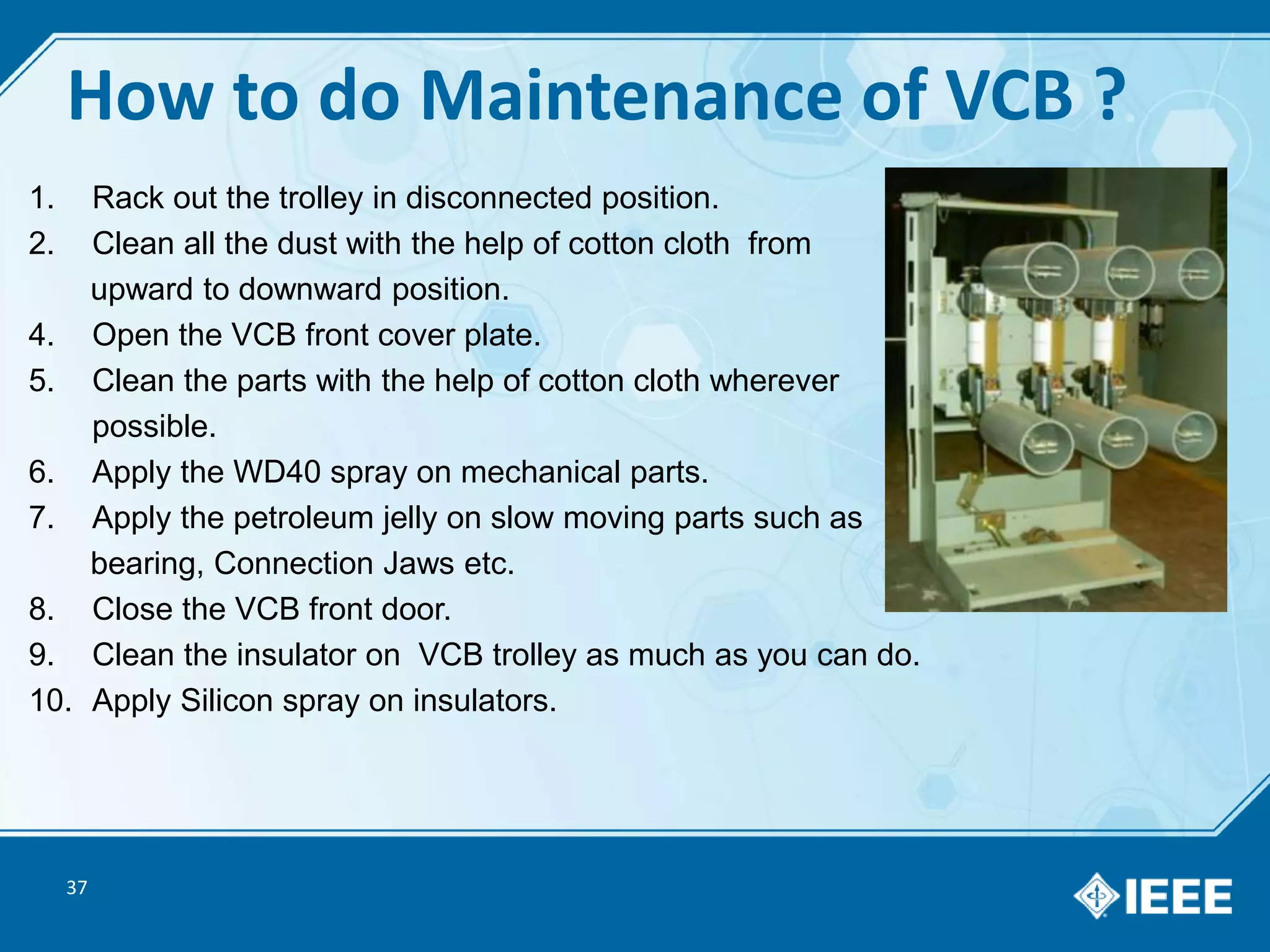
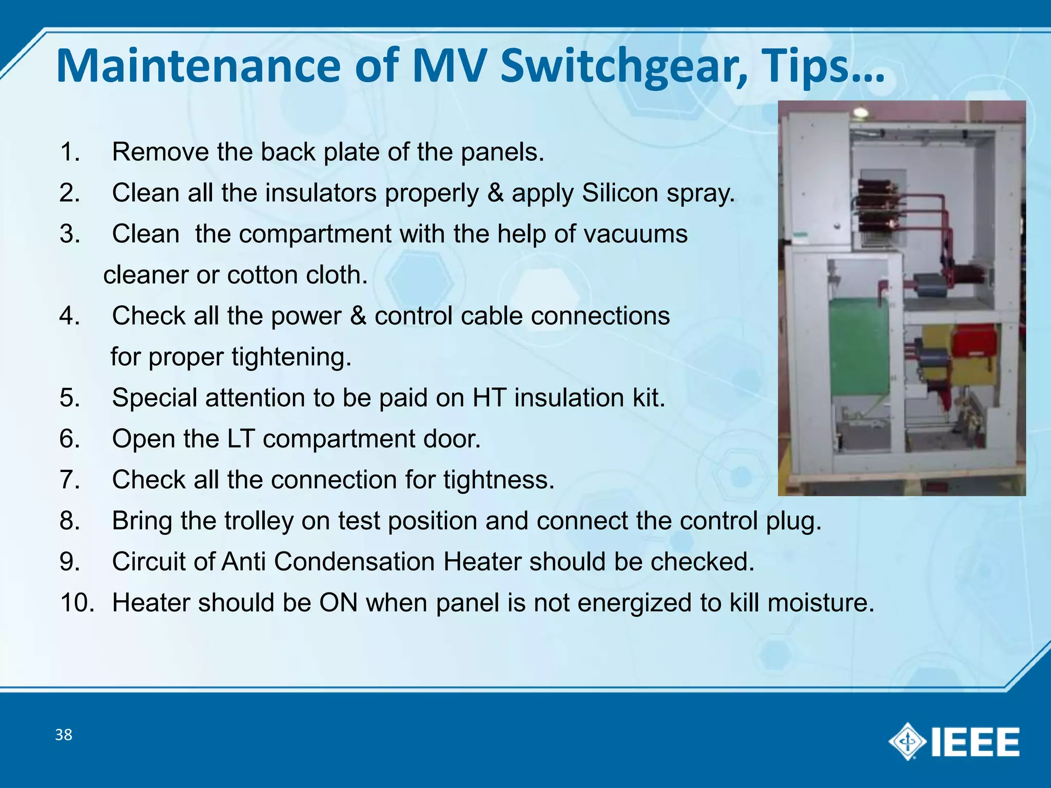
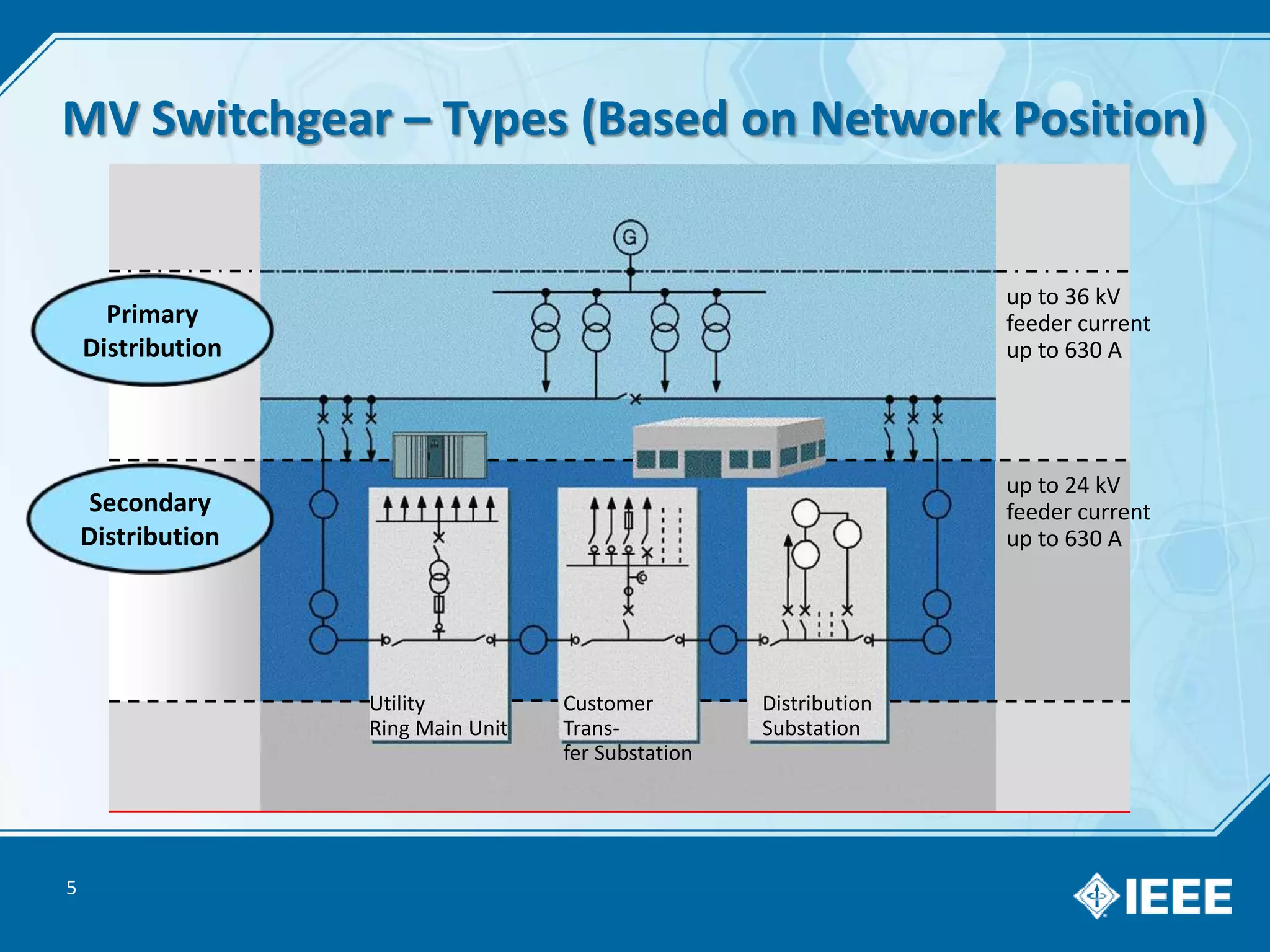
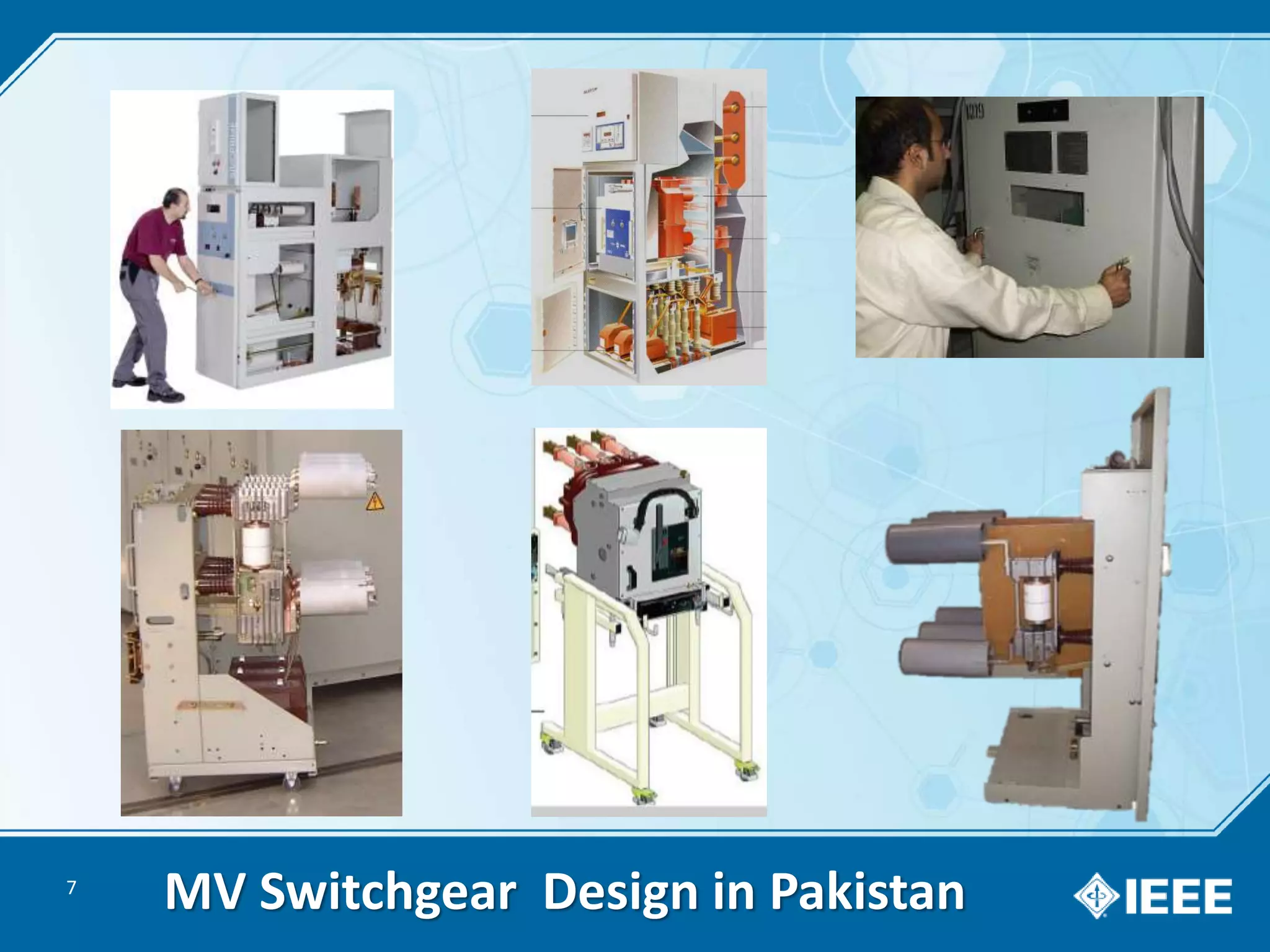
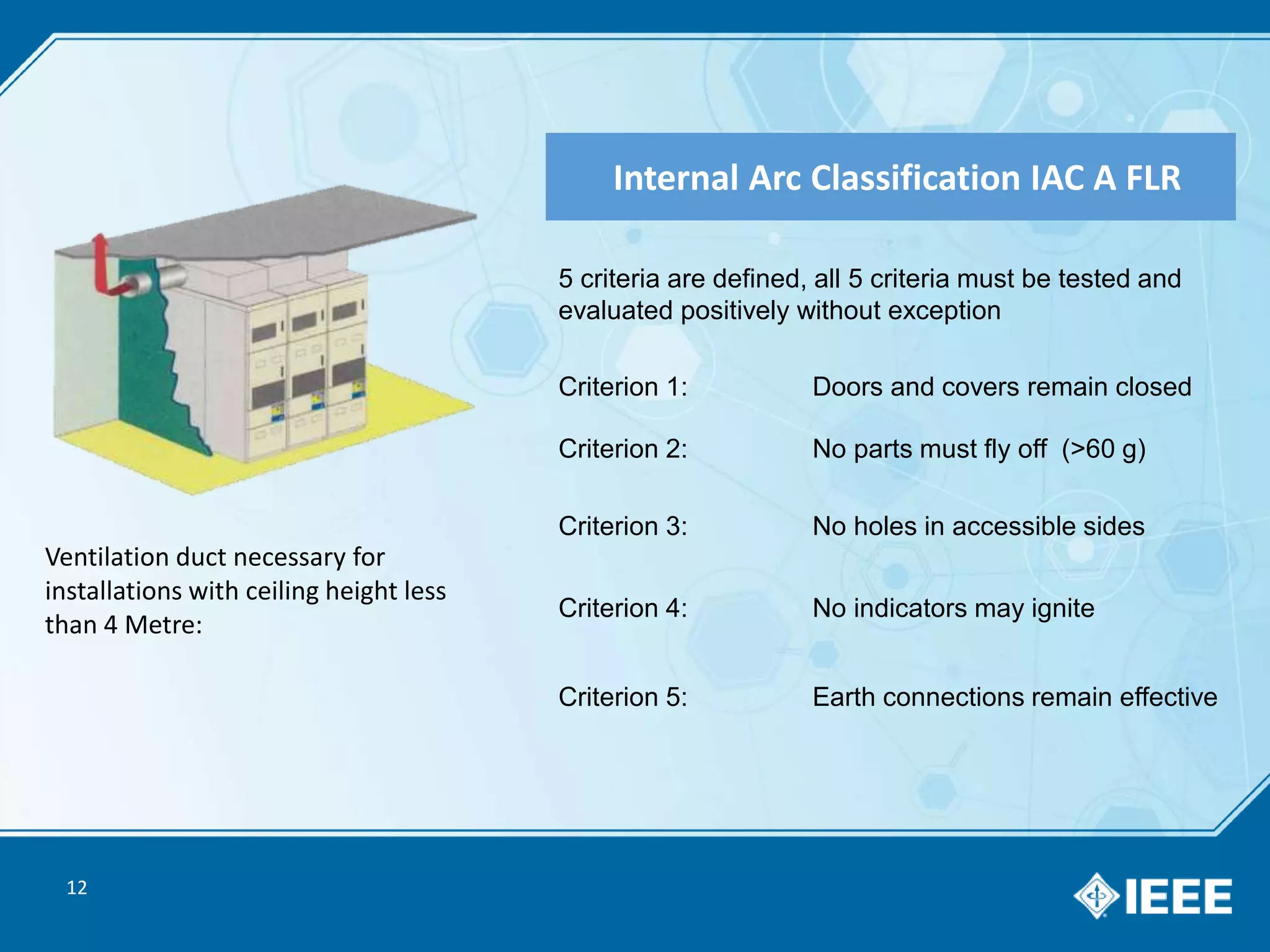
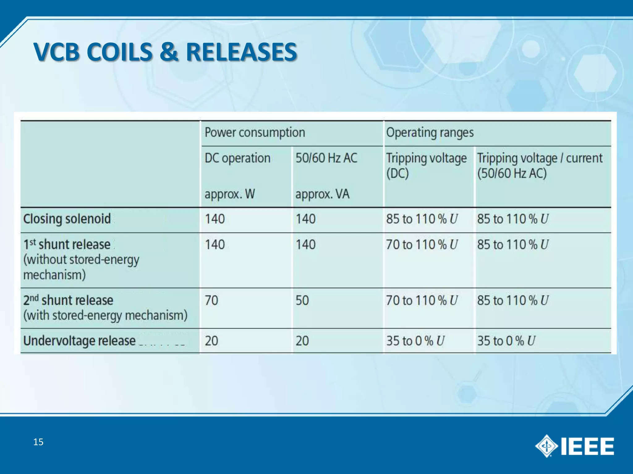
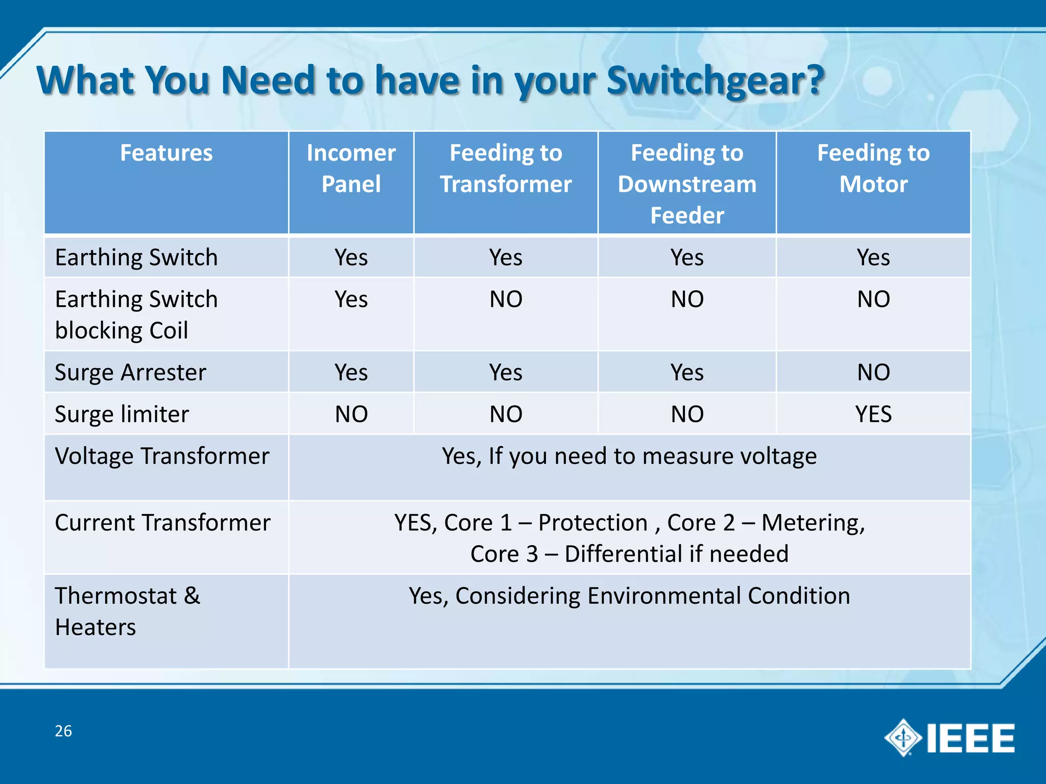
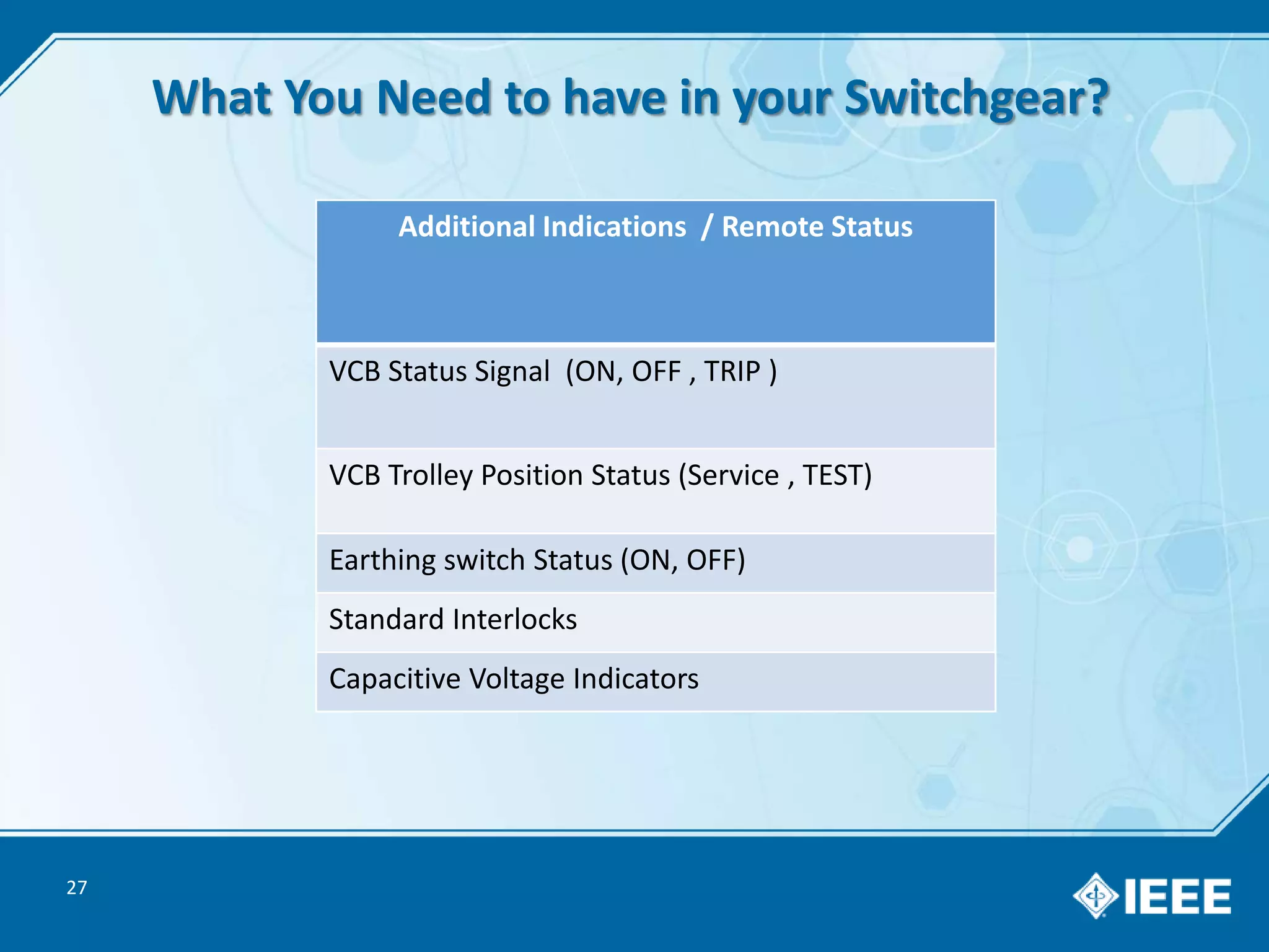
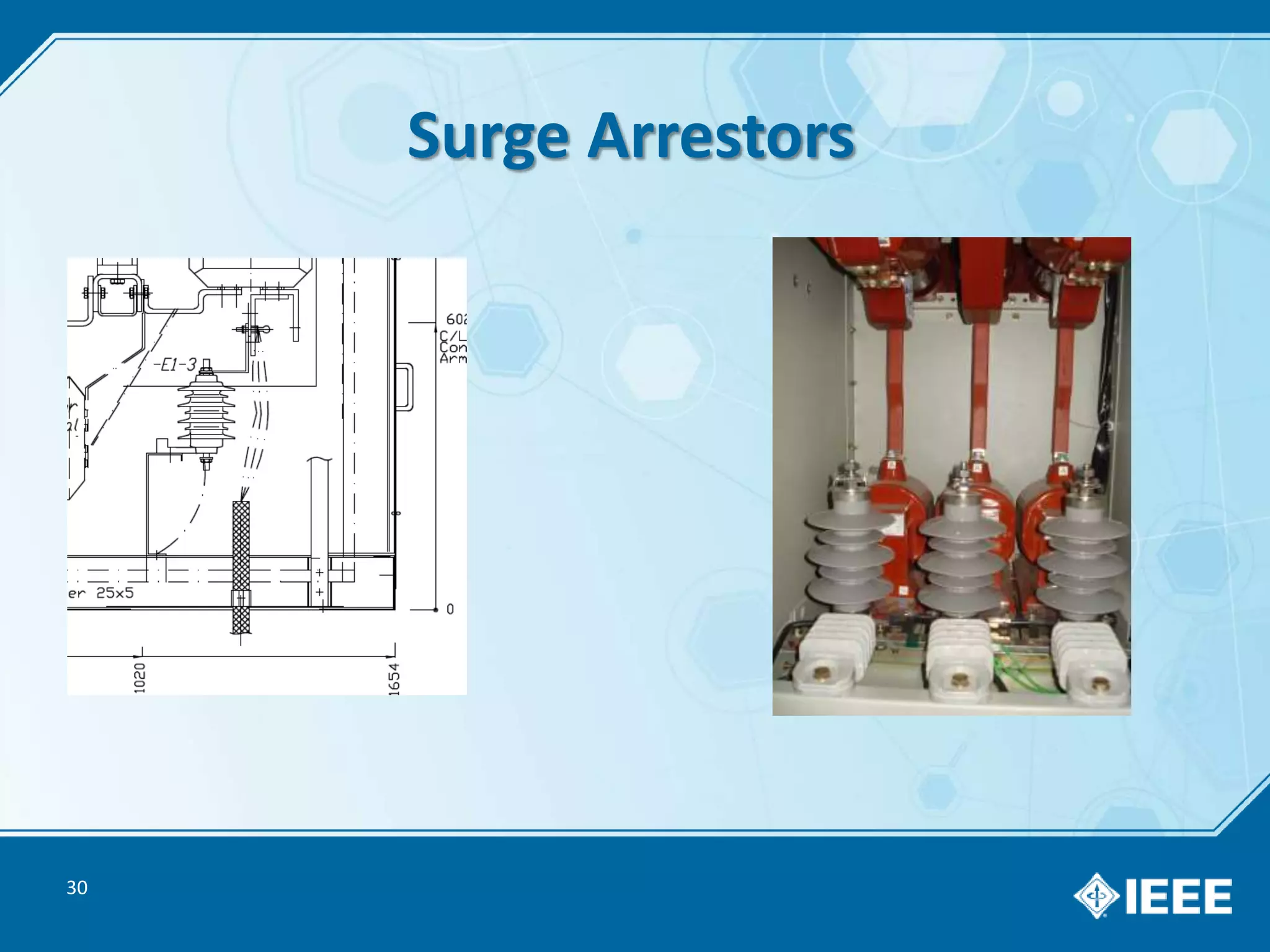
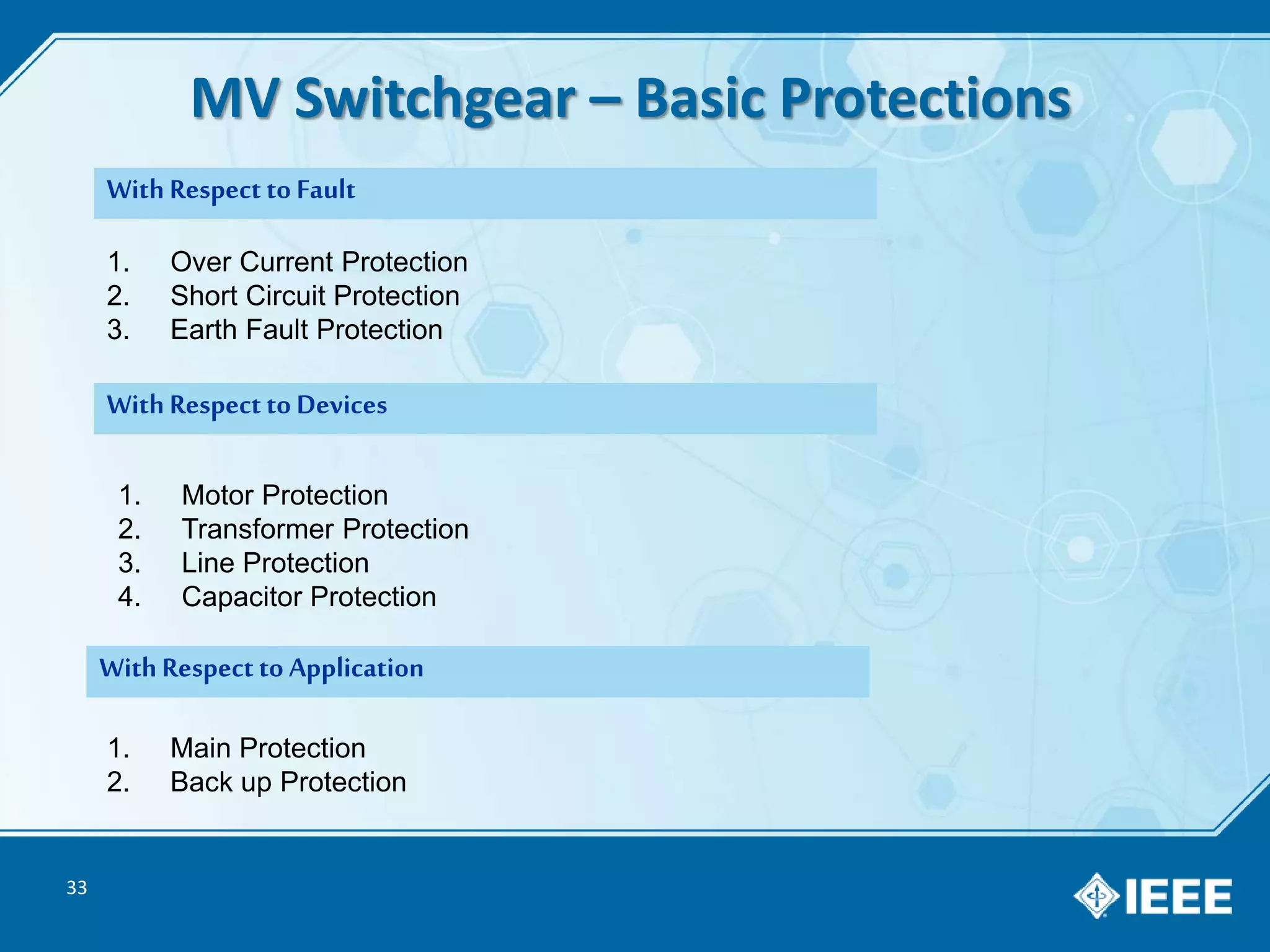
IMRAN ZAFAR
Country Manager – Enercon Pakistan
Member Local Council – IEEEP Karachi Centre
Secretary – IEEE PES Society
WhatsApp : +92 335 2224287
E-mail : imran@enercon-eng.com.sg
1
2
MV SWITCHGEAR
Network Location
Technology
Electrical Ratings
Application in Circuit
Everything You Would Need To Know…
Electrical Network in Pakistan
3
WAPDA
K-Electric
IPPs
PAEC
NTDC
K-Electric
GRID STATION
DISCOs
K-Electric
SUBSTATION
13-18kV
500kV, 220kV , 132kV
11kV
11kV400V
4
Types of Electricity Consumers
Transmission line
500, 220, 132kV
220kV /132kV
Consumer
11kV Consumer
400V Consumer
230V Consumer
Own Generation
Power Generation
Up to 18kV
5
MV Switchgear – Types (Based on Network Position)
primary
distribution
up to 36 kV
feeder current
up to 630 A
Customer
Trans-
fer Substation
Distribution
Substation
secondary
distributio
n
up to 24 kV
feeder current
up to 630 A
Utility
Ring Main Unit
Secondary
Distribution
Primary
Distribution
6
AIR
INSULATED
GAS
INSULATED
MV Switchgear – Types (Based on Technology)
MV Switchgear Video
7
MV Switchgear Design in Pakistan
8
MV Switchgear – VCB Trolley Design
Cable Compartment
BUSBAR
Compartment
Low-voltage compartment
BUSBARS
VCB
VCB Trolley
CTs
Cables
Earthing Switch
PTs
LV Compartment
VCB Compartment
9
MV Switchgear – Truck Type Design
Low-voltage compartment
BUSBARS
VCB
VCB Truck
CTs
PTs
Cables
10
MV Switchgear –WAPDA / KE GRID DESIGN
KESC / WAPDA GRID
LV compartment
BUSBARS
VCB
Door + VCB Trolley
CTs
PTs
Cables
11
Type & Routine Test According to IEC – 62271-200
TYPE TEST (MANDATORY)
 Tests to verify insulation level
 Tests to prove temperature-rise
 Tests to prove the capability of main and earthing circuits with
rated peak withstand current and short-time withstand current
 Tests to prove making and breaking capacity
of included switching devices
 Tests to prove satisfactory mechanical functions
 Tests to verify the protection of personal safety
 Tests of internal arc classification
(mandatory type test, where applicable)
ROUTINE TEST
 Dielectric test of main circuit
at power-frequency voltage
 Test of auxiliary and control circuits
 Evidence of mechanical functioning
12
Ventilation duct necessary for
installations with ceiling height less
than 4 Metre:
5 criteria are defined, all 5 criteria must be tested and
evaluated positively without exception
Criterion 1: Doors and covers remain closed
Criterion 2: No parts must fly off (>60 g)
Criterion 3: No holes in accessible sides
Criterion 4: No indicators may ignite
Criterion 5: Earth connections remain effective
Internal Arc Classification IAC A FLR
13
14
8-15µΩ
>6<20mm
10-9 Bar
Interrupter bottles with laser welding in vacuum corner
Achieve High Di-electric Strength with only 6-10mm due to low pressure.
Vacuum Interrupter Video
15
VCB COILS & RELEASES
16
Operating Times Operating times at rated voltage of secondary
circuit
17
Electrical Terms for MV Switchgear
3.3, 3.6, 4.8, 6.6 KV
20kV, 22kV
Rated Voltage
 Applicable Standard (IEC, NEMA, BS, etc.)
 Rated Voltage, Service Voltage,
 Short Duration Power Frequency Withstand Voltage
 Basic Impulse Lightning Test Voltage
 Correction Factor
10kV , 11kV
13.8kV, 15kV
Electrical
Ratings
33kV
Service VoltagePower Frequency Voltage
BIL Voltage
18
Electrical Terms for MV Switchgear
Rated Current
630A, 800 A
1250 A, 1600A
2000A , 2500A
3200A, 4000A
Rated Short Circuit
20kA
25kA
31.5kA
40kA , 50kA
Rated Frequency
50 Hz , 60Hz
 Rated Current, Rated Busbar Current, Rated Feeder Current
 Service Current ,
 Short-Circuit Making Current , Short-Circuit Breaking Current
 Rated Frequency
Electrical
Ratings
19
Electrical Ratings Variant 1 Variant 2 Variant 3
Rated voltage, max. kV 12 17.5 24
Rated short-circuit
current, max.
kA 25 31.5 40/50 25
Rated busbar
current, max.
A 2500 2500 4000
Rated feeder current,
max.
A 1000 1250 2500 2000 2500 2500 4000
1250A, 2500A BB, 31.5kA , 12/28/75kV , 50Hz
How you would specify Complete Rating of MV Switchgear ?
20
Altitude Correction Factor
21
132
/
11kV Typical MV Line-up
22
25
What You Need to Have in Your MV Switchgear?
Features Incomer
Panel
Feeding to
Transformer
Feeding to
Downstream Feeder
Feeding to Motor
Basic Protections
Relays
Yes Yes Yes Yes
Special
Protections
BUSBAR
Diff
Bucholz,
Differential
Directional ,
Distance
Differential
Ammeter
Voltmeter
Yes Yes Yes Yes
Energy Meter Yes Depending on Customer Wish
Test Plug Optional Choice, depend on Budget & Specs
VCB Motor
VCB UVT coil
Yes, if you need to operate your VCB via Electrical Switch or through Remote
Trip Circuit
Supervision
Optional Choice, depend on Budget & Specs
VCB Operation
Counter
Yes Yes Yes Yes
26
What You Need to have in your Switchgear?
Features Incomer
Panel
Feeding to
Transformer
Feeding to
Downstream
Feeder
Feeding to
Motor
Earthing Switch Yes Yes Yes Yes
Earthing Switch
blocking Coil
Yes NO NO NO
Surge Arrester Yes Yes Yes NO
Surge limiter NO NO NO YES
Voltage Transformer Yes, If you need to measure voltage
Current Transformer YES, Core 1 – Protection , Core 2 – Metering,
Core 3 – Differential if needed
Thermostat &
Heaters
Yes, Considering Environmental Condition
27
What You Need to have in your Switchgear?
Additional Indications / Remote Status
VCB Status Signal (ON, OFF , TRIP )
VCB Trolley Position Status (Service , TEST)
Earthing switch Status (ON, OFF)
Standard Interlocks
Capacitive Voltage Indicators
28
Current & Voltage Transformers
Measuring CTs
Potential Transformer
Protection CTs
29
A
B
C
D
E
Earthing Switch
30
Surge Arrestors
31
The Purpose of Protection…
The damages aredue to:
 Short Circuitin system
 Abnormal condition in the system
The Protection can not prevent system faults andabnormal conditions
 But it can
 limit the damage caused by short circuits andabnormal conditions.
While
 Protecting people andequipment from damage
32
The Purpose of installation of protection relay is…
 To protect the veryexpensive equipment likeTransformers, Generators, Motors, Cables and
other installed equipment.
 To ensurethe interruption of supply to minimumnumberof consumers.
 To minimise the production losses of thefactories.
 To avoid major Countrylevel shut downs.
33
MV Switchgear – Basic Protections
1. Over Current Protection
2. Short Circuit Protection
3. Earth Fault Protection
1. Motor Protection
2. Transformer Protection
3. Line Protection
4. Capacitor Protection
1. Main Protection
2. Back up Protection
WithRespect to Application
WithRespect to Devices
WithRespect to Fault
34
MV Switchgear – Basic Protections
• O/L, S/C and E/F protection
• Phase sequence protection
• Surge protection
• Reverse power protection
• Thermistor protection
Generators
• O/L, S/C and E/F protection
• Thermistor protection
• Phase sequence protection
• O/V & U/V protection
•Thermistor protection
Motors
• O/C, S/C and E/F protection
• Bucholz protection
• Differential protection
Transformers
36
1. Provides service reliability.
2. Ensures longer life of switchgear.
3. Minimizes fault probability.
4. Increases productivity.
5. Ensures Safety of personnel
6. Saves Investment.
Finally , Maintenance of MV Switchgear, Why it is so Important?
How to do Maintenance of VCB ?
37
1. Rack out the trolley in disconnected position.
2. Clean all the dust with the help of cotton cloth from
upward to downward position.
4. Open the VCB front cover plate.
5. Clean the parts with the help of cotton cloth wherever
possible.
6. Apply the WD40 spray on mechanical parts.
7. Apply the petroleum jelly on slow moving parts such as
bearing, Connection Jaws etc.
8. Close the VCB front door.
9. Clean the insulator on VCB trolley as much as you can do.
10. Apply Silicon spray on insulators.
Maintenance of MV Switchgear, Tips…
38
1. Remove the back plate of the panels.
2. Clean all the insulators properly & apply Silicon spray.
3. Clean the compartment with the help of vacuums
cleaner or cotton cloth.
4. Check all the power & control cable connections
for proper tightening.
5. Special attention to be paid on HT insulation kit.
6. Open the LT compartment door.
7. Check all the connection for tightness.
8. Bring the trolley on test position and connect the control plug.
9. Circuit of Anti Condensation Heater should be checked.
10. Heater should be ON when panel is not energized to kill moisture.
39
How IEEE Membership benefit you?
• Giving back to Society
• Social Networking & Connection with Community
• Number of Tangible & Intangible Benefits
40
Becoming A Member of IEEE
If you don’t have credit card:
• Send IEEE Account number, Password and payment to mohd_shahab@hotmail.com.
• Total payment in PKR = (13.50*169) + 7 per USD
= 2375 PKR
Note:
• 169 is today’s dollar rate. It might change
• PKR 7 per USD for taxes on foreign transaction / other charges.
Career Phase Price
Student USD 13.50 (For half year)
Professional USD 79.00
41

MV Switchgear from IEEE

  • 1.
    IMRAN ZAFAR Country Manager– Enercon Pakistan Member Local Council – IEEEP Karachi Centre Secretary – IEEE PES Society WhatsApp : +92 335 2224287 E-mail : imran@enercon-eng.com.sg 1
  • 2.
    2 MV SWITCHGEAR Network Location Technology ElectricalRatings Application in Circuit Everything You Would Need To Know…
  • 3.
    Electrical Network inPakistan 3 WAPDA K-Electric IPPs PAEC NTDC K-Electric GRID STATION DISCOs K-Electric SUBSTATION 13-18kV 500kV, 220kV , 132kV 11kV 11kV400V
  • 4.
    4 Types of ElectricityConsumers Transmission line 500, 220, 132kV 220kV /132kV Consumer 11kV Consumer 400V Consumer 230V Consumer Own Generation Power Generation Up to 18kV
  • 5.
    5 MV Switchgear –Types (Based on Network Position) primary distribution up to 36 kV feeder current up to 630 A Customer Trans- fer Substation Distribution Substation secondary distributio n up to 24 kV feeder current up to 630 A Utility Ring Main Unit Secondary Distribution Primary Distribution
  • 6.
    6 AIR INSULATED GAS INSULATED MV Switchgear –Types (Based on Technology) MV Switchgear Video
  • 7.
  • 8.
    8 MV Switchgear –VCB Trolley Design Cable Compartment BUSBAR Compartment Low-voltage compartment BUSBARS VCB VCB Trolley CTs Cables Earthing Switch PTs LV Compartment VCB Compartment
  • 9.
    9 MV Switchgear –Truck Type Design Low-voltage compartment BUSBARS VCB VCB Truck CTs PTs Cables
  • 10.
    10 MV Switchgear –WAPDA/ KE GRID DESIGN KESC / WAPDA GRID LV compartment BUSBARS VCB Door + VCB Trolley CTs PTs Cables
  • 11.
    11 Type & RoutineTest According to IEC – 62271-200 TYPE TEST (MANDATORY)  Tests to verify insulation level  Tests to prove temperature-rise  Tests to prove the capability of main and earthing circuits with rated peak withstand current and short-time withstand current  Tests to prove making and breaking capacity of included switching devices  Tests to prove satisfactory mechanical functions  Tests to verify the protection of personal safety  Tests of internal arc classification (mandatory type test, where applicable) ROUTINE TEST  Dielectric test of main circuit at power-frequency voltage  Test of auxiliary and control circuits  Evidence of mechanical functioning
  • 12.
    12 Ventilation duct necessaryfor installations with ceiling height less than 4 Metre: 5 criteria are defined, all 5 criteria must be tested and evaluated positively without exception Criterion 1: Doors and covers remain closed Criterion 2: No parts must fly off (>60 g) Criterion 3: No holes in accessible sides Criterion 4: No indicators may ignite Criterion 5: Earth connections remain effective Internal Arc Classification IAC A FLR
  • 13.
  • 14.
    14 8-15µΩ >6<20mm 10-9 Bar Interrupter bottleswith laser welding in vacuum corner Achieve High Di-electric Strength with only 6-10mm due to low pressure. Vacuum Interrupter Video
  • 15.
  • 16.
    16 Operating Times Operatingtimes at rated voltage of secondary circuit
  • 17.
    17 Electrical Terms forMV Switchgear 3.3, 3.6, 4.8, 6.6 KV 20kV, 22kV Rated Voltage  Applicable Standard (IEC, NEMA, BS, etc.)  Rated Voltage, Service Voltage,  Short Duration Power Frequency Withstand Voltage  Basic Impulse Lightning Test Voltage  Correction Factor 10kV , 11kV 13.8kV, 15kV Electrical Ratings 33kV Service VoltagePower Frequency Voltage BIL Voltage
  • 18.
    18 Electrical Terms forMV Switchgear Rated Current 630A, 800 A 1250 A, 1600A 2000A , 2500A 3200A, 4000A Rated Short Circuit 20kA 25kA 31.5kA 40kA , 50kA Rated Frequency 50 Hz , 60Hz  Rated Current, Rated Busbar Current, Rated Feeder Current  Service Current ,  Short-Circuit Making Current , Short-Circuit Breaking Current  Rated Frequency Electrical Ratings
  • 19.
    19 Electrical Ratings Variant1 Variant 2 Variant 3 Rated voltage, max. kV 12 17.5 24 Rated short-circuit current, max. kA 25 31.5 40/50 25 Rated busbar current, max. A 2500 2500 4000 Rated feeder current, max. A 1000 1250 2500 2000 2500 2500 4000 1250A, 2500A BB, 31.5kA , 12/28/75kV , 50Hz How you would specify Complete Rating of MV Switchgear ?
  • 20.
  • 21.
  • 22.
  • 23.
    25 What You Needto Have in Your MV Switchgear? Features Incomer Panel Feeding to Transformer Feeding to Downstream Feeder Feeding to Motor Basic Protections Relays Yes Yes Yes Yes Special Protections BUSBAR Diff Bucholz, Differential Directional , Distance Differential Ammeter Voltmeter Yes Yes Yes Yes Energy Meter Yes Depending on Customer Wish Test Plug Optional Choice, depend on Budget & Specs VCB Motor VCB UVT coil Yes, if you need to operate your VCB via Electrical Switch or through Remote Trip Circuit Supervision Optional Choice, depend on Budget & Specs VCB Operation Counter Yes Yes Yes Yes
  • 24.
    26 What You Needto have in your Switchgear? Features Incomer Panel Feeding to Transformer Feeding to Downstream Feeder Feeding to Motor Earthing Switch Yes Yes Yes Yes Earthing Switch blocking Coil Yes NO NO NO Surge Arrester Yes Yes Yes NO Surge limiter NO NO NO YES Voltage Transformer Yes, If you need to measure voltage Current Transformer YES, Core 1 – Protection , Core 2 – Metering, Core 3 – Differential if needed Thermostat & Heaters Yes, Considering Environmental Condition
  • 25.
    27 What You Needto have in your Switchgear? Additional Indications / Remote Status VCB Status Signal (ON, OFF , TRIP ) VCB Trolley Position Status (Service , TEST) Earthing switch Status (ON, OFF) Standard Interlocks Capacitive Voltage Indicators
  • 26.
    28 Current & VoltageTransformers Measuring CTs Potential Transformer Protection CTs
  • 27.
  • 28.
  • 29.
    31 The Purpose ofProtection… The damages aredue to:  Short Circuitin system  Abnormal condition in the system The Protection can not prevent system faults andabnormal conditions  But it can  limit the damage caused by short circuits andabnormal conditions. While  Protecting people andequipment from damage
  • 30.
    32 The Purpose ofinstallation of protection relay is…  To protect the veryexpensive equipment likeTransformers, Generators, Motors, Cables and other installed equipment.  To ensurethe interruption of supply to minimumnumberof consumers.  To minimise the production losses of thefactories.  To avoid major Countrylevel shut downs.
  • 31.
    33 MV Switchgear –Basic Protections 1. Over Current Protection 2. Short Circuit Protection 3. Earth Fault Protection 1. Motor Protection 2. Transformer Protection 3. Line Protection 4. Capacitor Protection 1. Main Protection 2. Back up Protection WithRespect to Application WithRespect to Devices WithRespect to Fault
  • 32.
    34 MV Switchgear –Basic Protections • O/L, S/C and E/F protection • Phase sequence protection • Surge protection • Reverse power protection • Thermistor protection Generators • O/L, S/C and E/F protection • Thermistor protection • Phase sequence protection • O/V & U/V protection •Thermistor protection Motors • O/C, S/C and E/F protection • Bucholz protection • Differential protection Transformers
  • 33.
    36 1. Provides servicereliability. 2. Ensures longer life of switchgear. 3. Minimizes fault probability. 4. Increases productivity. 5. Ensures Safety of personnel 6. Saves Investment. Finally , Maintenance of MV Switchgear, Why it is so Important?
  • 34.
    How to doMaintenance of VCB ? 37 1. Rack out the trolley in disconnected position. 2. Clean all the dust with the help of cotton cloth from upward to downward position. 4. Open the VCB front cover plate. 5. Clean the parts with the help of cotton cloth wherever possible. 6. Apply the WD40 spray on mechanical parts. 7. Apply the petroleum jelly on slow moving parts such as bearing, Connection Jaws etc. 8. Close the VCB front door. 9. Clean the insulator on VCB trolley as much as you can do. 10. Apply Silicon spray on insulators.
  • 35.
    Maintenance of MVSwitchgear, Tips… 38 1. Remove the back plate of the panels. 2. Clean all the insulators properly & apply Silicon spray. 3. Clean the compartment with the help of vacuums cleaner or cotton cloth. 4. Check all the power & control cable connections for proper tightening. 5. Special attention to be paid on HT insulation kit. 6. Open the LT compartment door. 7. Check all the connection for tightness. 8. Bring the trolley on test position and connect the control plug. 9. Circuit of Anti Condensation Heater should be checked. 10. Heater should be ON when panel is not energized to kill moisture.
  • 36.
    39 How IEEE Membershipbenefit you? • Giving back to Society • Social Networking & Connection with Community • Number of Tangible & Intangible Benefits
  • 37.
    40 Becoming A Memberof IEEE If you don’t have credit card: • Send IEEE Account number, Password and payment to mohd_shahab@hotmail.com. • Total payment in PKR = (13.50*169) + 7 per USD = 2375 PKR Note: • 169 is today’s dollar rate. It might change • PKR 7 per USD for taxes on foreign transaction / other charges. Career Phase Price Student USD 13.50 (For half year) Professional USD 79.00
  • 38.