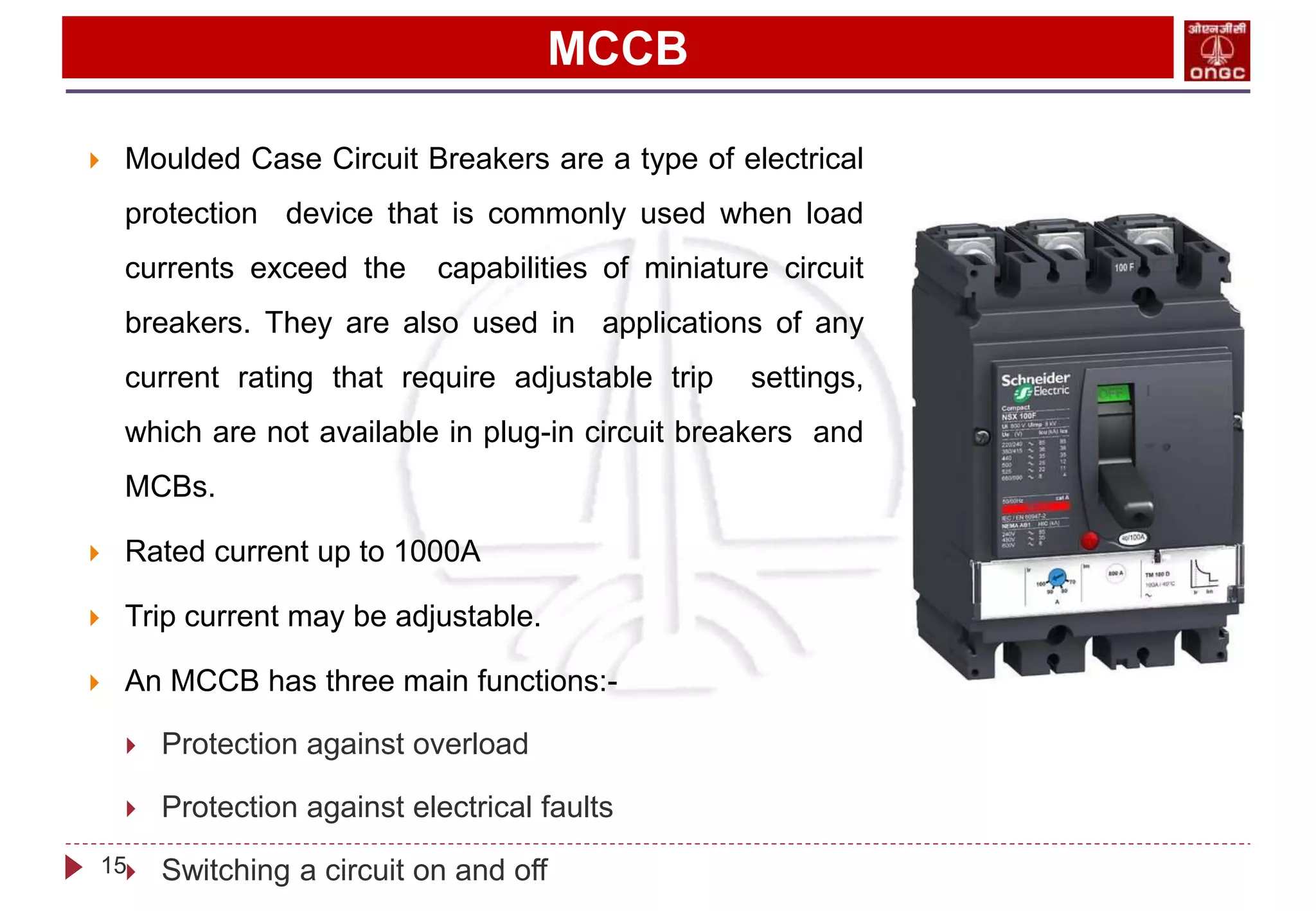
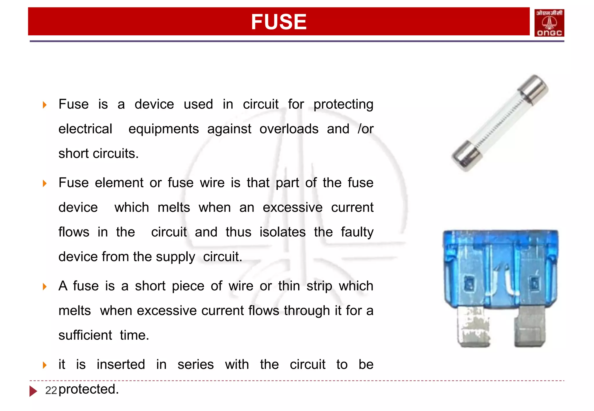
LV SWITCHGEAR
BY
Switchgear
• Switchgear is a combination of switching devices such as :-
o Protection devices
o Switching devices
o Control and sensing devices
• The apparatus used for switching, controlling & protecting the electrical circuits &
equipments are known as switchgear.
• The switchgear is essentially used with switching & interrupting currents either under
normal or abnormal operating conditions.
• It consists of devices such as switches, fuses, circuit breakers, relays etc.
• Basically every electric circuit needs a switching device and a protecting device.
2
SWITCHGEAR
3
SWITCHGEAR
4
ESSENTIAL FEATURES OF SWITCHGEAR
5
 COMPLETE RELIABILITY
 DISCRIMINATION
 QUICK OPEARATION
 PROVISION FOR MANUAL CONTROL
 PROVISION FOR INSTRUMENTS
COMPLETE RELIABILITY
 The ability of the portion system to operate under the predetermined conditions
is known as reliability.
 When fault occur on any power system , the switchgear must operate to isolate
the faulty section from remaining circuit.
6
DISCRIMINATION
 When fault occurs on any section of the power system the switchgear must be able
to discriminate between the faulty section and the healthy section. It should the
faulty section from the system with affecting the healthy section.
7
QUICK OPERATION
 When fault occurs on any part of the power system, the switchgear must operate
quickly so that no damage is done to generators, transformers, and other
equipment by the short-circuit currents. If the fault is not cleared by the switchgear
quickly, it is likely to spread into the healthy parts, thus endangering complete shut
down of the system.
8
PROVISION FOR INSTRUMENTS
 There must be provision for instruments which may be required. These may be in
the form of ammeter or voltmeter on the unit itself or the necessary operation
current & voltage transformers for connecting to the main switch board or a
separate instrument panel.
9
SWITCHGEAR EQUIPMENTS
 Protection devices
 Circuit breakers(MCB)
 MCCB(Moulded case circuit breaker)
 Relays
 Fuse
 Switching devices
 Switches
 isolator
 Contactors
 Control and sensing devices
 CT(current transformer)
 Ammeter
 Energy meter
10
CIRCUIT BREAKERS
 Definition
 A circuit breaker is a device which can make
or break a circuit either manually or
automatically under normal or abnormal
condition.
 Function
 A CB is a switching and current interrupting
device.
11
MINIATURE CIRCUIT BREAKERS
 As the name implies it is the miniature form of
circuit breaker.
 It is easy to handle and provide complete safety to
human beings.
 Operating principle
 Two contacts called electrode remains closed
under normal operating conditions. When fault
occurs on any part of the system, the trip coil
of the circuit breaker get energized and
contacts are separated.
 A circuit breaker essentially consists of fixed and
moving contacts.
12
WORKING OF MCBs
13
MINIATURE CIRCUIT BREAKER
 Miniature Circuit Breakers are electromechanical devices which protect an electric
circuit from an over current.
 The over current, in an electrical circuit, may result from short circuit, overload or
faulty design.
 Miniature Circuit Breakers are used to protect lower current circuits and have the
following Specifications :- Current rating - Amperes
 Short Circuit Rating - Kilo Amperes (kA)
 Rated current not more than 100A.
 Trip characteristics normally not adjustable.
14
MCCB
 Moulded Case Circuit Breakers are a type of electrical
protection device that is commonly used when load
currents exceed the capabilities of miniature circuit
breakers. They are also used in applications of any
current rating that require adjustable trip settings,
which are not available in plug-in circuit breakers and
MCBs.
 Rated current up to 1000A
 Trip current may be adjustable.
 An MCCB has three main functions:-
 Protection against overload
 Protection against electrical faults
 Switching a circuit on and off
15
RELAY
 A relay may also be called an “electromagnetic
switch”.
 Protective relay is a device designed to trip a circuit
breaker when fault is detected.
 It is operating on moving parts to provide detection
of abnormal condition.
 Definition
 A relay is a automatic device which senses an
abnormal condition of electric circuit and closes
its contacts.
 There are two basic classifications of relays:-
 Electromechanical Relays
 Solid State Relays
16
TYPES OF RELAYS
17
RELAY
 One main difference between them is electromechanical relays have moving parts,
whereas solid state relays have no moving parts.
 in conventional electromagnetic relay the measurement of quantities is done by
comparing operating torque/force with restraining torque/force. the electromagnetic
relay operates when the operating torque/force is greater than the restraining
torque/force. in electromagnetic relays the pick up is obtain by the movement of
movable element in the relay.
 A static relay is the relay which uses solid state components like transistors, diodes
etc., for the measurement or comparison of electrical quantities.
18
CURRENT TRANSFORMERS
 The transformer which is used for the measurement of current is known as current
transformer.
 Current transformer are used in electrical power system for stepping down currents
of the system for metering and protection purpose.
 The current transformer has primary coil of one or less no. of turns of thick wire
which is connected in series with the transmission line.
 The secondary consist of large number of turns of fine wire.
 A CT(current transformer) functions with the same basic working principle of
electrical power transformer.
19
CURRENT TRANSFORMERS
 The current transformer gives the value
of current upto 5A.
 The secondary and primary winding are
insulated to each other.
 Classification of current transformer On
the basis of primary winding
 Wound type
 Bar type
20
CURRENT TRANSFORMERS
21
FUSE
 Fuse is a device used in circuit for protecting
electrical equipments against overloads and /or
short circuits.
 Fuse element or fuse wire is that part of the fuse
device which melts when an excessive current
flows in the circuit and thus isolates the faulty
device from the supply circuit.
 A fuse is a short piece of wire or thin strip which
melts when excessive current flows through it for a
sufficient time.
 it is inserted in series with the circuit to be
protected.
22
FUSE
 Desirable qualities of fuse elements
 Low melting point
 Low ohmic losses
 High conductivity
 Low cost
23
OVERLOAD RELAY
 Overload relays protect the motor, motor branch
circuit, and motor branch circuit components from
excessive heat from the overload condition.
 Overload relays are part of the motor starter
(assembly of contactor plus overload relay). They
protect the motor by monitoring the current flowing in
the circuit. If the current rises above a certain limit
over a certain period of time, then the overload relay
will trip, operating an auxiliary contact which interrupts
the motor control circuit, de-energizing the contactor.
24
THERMAL BIMETALLIC OLR
 A thermal overload relay works in the principle of
electro-thermal properties in a bimetallic strip. It is
placed in the motor circuit in such a way that the
current to the motor flows through its poles. The
bimetallic strip gets heated up by the current
directly or indirectly and when the current flow
exceeds the set value, it bends.
 B = Trip slide
C = Trip lever
D = Contact lever
E = Compensation bimetal strip
25
PARTS OF A THERMAL OLR
26
TRIP CLASS OF OVERLOAD RELAY
 The time taken by them to open the contactor
during overloads is specified by the trip class. It is
commonly classified into Class 10, Class 20,
Class 30 and Class 5. The OLR trips in 10
seconds, 20 seconds, 30 seconds and 5 seconds
respectively at 600% of full load current to the
motor.
 Class 10 and Class 20 are very commonly used
ones. Class 30 overload relays are used for
protection of motors driving high inertia loads and
Class 5 relays are used for the motors requiring
very fast tripping.
27
OLR SETTING
28
SPACE HEATERS
 A space heater is a device used to heat a single,
or a small area.
 Space heaters are ideal for prevention of
condensation, corrosion, leakage currents in LT &
HT Switchgear panel boards.
 The space heater keeps the internal temperature
of the motor above the ambient dew point while
the motor is OFF. The heater helps to prevent
condensation from forming inside the motor which
can be damaging to motor windings, bearings and
electrical connections.
29
GROUNDING
 The term grounding is commonly used in the electrical industry to mean both
“equipment grounding” and “system grounding”. Equipment grounding means the
connection of earth ground to non-current carrying conductive materials such as
conduit, cable trays, junction boxes, enclosures, and motor frames.
 Types of Grounded System
 Three different types of grounding systems that are important are listed below.
 Ungrounded Systems
 Resistance Grounded Systems
 Solidly Grounded Systems
30
FACTORS AFFECTING THE GROUNDING
 Following are the factors that impact the performance of any ground electrode:
 Material used in Grounding system
 Ground Electrode (Length or Depth, diameter, number of ground electrodes)
 Soil (Type, Moisture content, Temperature, Resistivity, Quantity of salt)
 Ground system design
 Location of the earth pit
31
LIGHTING SYSTEM
 Proper lighting
 Regular maintenance
 Explosion proof
32
CONTACTORS
 A contactor is an electrically-
controlled switch used for switching
an electrical power circuit. A
contactor is typically controlled by a
circuit which has a much lower
power level than the switched circuit,
such as a 24-volt coil electromagnet
controlling a 230-volt motor switch.
33
CONSTRUCTION OF CONTACTORS
34
WORKING OF CONTACTORS
35
AC CONTACTORS
 A shading coil is a single turn of conducting material
mounted in the face of the magnet assembly or
armature. The alternating main magnetic flux induces
currents in the shading coil and these currents set up
auxiliary magnetic flux which is out of phase from the
main flux. The auxiliary flux produces a magnetic pull
out of phase from the pull due to the main flux and this
keeps the armature sealed-in when the main flux falls
to zero (which occurs 100 times per second with 50
cycles ac). Without the shading coil, the armature
would tend to open each time the main flux goes
through zero. Excessive noise, wear on the magnet
faces, and heat would result.
36
37
38
Thank You
39

LV switchgear FINAL.pptx

  • 1.
  • 2.
    Switchgear • Switchgear isa combination of switching devices such as :- o Protection devices o Switching devices o Control and sensing devices • The apparatus used for switching, controlling & protecting the electrical circuits & equipments are known as switchgear. • The switchgear is essentially used with switching & interrupting currents either under normal or abnormal operating conditions. • It consists of devices such as switches, fuses, circuit breakers, relays etc. • Basically every electric circuit needs a switching device and a protecting device. 2
  • 3.
  • 4.
  • 5.
    ESSENTIAL FEATURES OFSWITCHGEAR 5  COMPLETE RELIABILITY  DISCRIMINATION  QUICK OPEARATION  PROVISION FOR MANUAL CONTROL  PROVISION FOR INSTRUMENTS
  • 6.
    COMPLETE RELIABILITY  Theability of the portion system to operate under the predetermined conditions is known as reliability.  When fault occur on any power system , the switchgear must operate to isolate the faulty section from remaining circuit. 6
  • 7.
    DISCRIMINATION  When faultoccurs on any section of the power system the switchgear must be able to discriminate between the faulty section and the healthy section. It should the faulty section from the system with affecting the healthy section. 7
  • 8.
    QUICK OPERATION  Whenfault occurs on any part of the power system, the switchgear must operate quickly so that no damage is done to generators, transformers, and other equipment by the short-circuit currents. If the fault is not cleared by the switchgear quickly, it is likely to spread into the healthy parts, thus endangering complete shut down of the system. 8
  • 9.
    PROVISION FOR INSTRUMENTS There must be provision for instruments which may be required. These may be in the form of ammeter or voltmeter on the unit itself or the necessary operation current & voltage transformers for connecting to the main switch board or a separate instrument panel. 9
  • 10.
    SWITCHGEAR EQUIPMENTS  Protectiondevices  Circuit breakers(MCB)  MCCB(Moulded case circuit breaker)  Relays  Fuse  Switching devices  Switches  isolator  Contactors  Control and sensing devices  CT(current transformer)  Ammeter  Energy meter 10
  • 11.
    CIRCUIT BREAKERS  Definition A circuit breaker is a device which can make or break a circuit either manually or automatically under normal or abnormal condition.  Function  A CB is a switching and current interrupting device. 11
  • 12.
    MINIATURE CIRCUIT BREAKERS As the name implies it is the miniature form of circuit breaker.  It is easy to handle and provide complete safety to human beings.  Operating principle  Two contacts called electrode remains closed under normal operating conditions. When fault occurs on any part of the system, the trip coil of the circuit breaker get energized and contacts are separated.  A circuit breaker essentially consists of fixed and moving contacts. 12
  • 13.
  • 14.
    MINIATURE CIRCUIT BREAKER Miniature Circuit Breakers are electromechanical devices which protect an electric circuit from an over current.  The over current, in an electrical circuit, may result from short circuit, overload or faulty design.  Miniature Circuit Breakers are used to protect lower current circuits and have the following Specifications :- Current rating - Amperes  Short Circuit Rating - Kilo Amperes (kA)  Rated current not more than 100A.  Trip characteristics normally not adjustable. 14
  • 15.
    MCCB  Moulded CaseCircuit Breakers are a type of electrical protection device that is commonly used when load currents exceed the capabilities of miniature circuit breakers. They are also used in applications of any current rating that require adjustable trip settings, which are not available in plug-in circuit breakers and MCBs.  Rated current up to 1000A  Trip current may be adjustable.  An MCCB has three main functions:-  Protection against overload  Protection against electrical faults  Switching a circuit on and off 15
  • 16.
    RELAY  A relaymay also be called an “electromagnetic switch”.  Protective relay is a device designed to trip a circuit breaker when fault is detected.  It is operating on moving parts to provide detection of abnormal condition.  Definition  A relay is a automatic device which senses an abnormal condition of electric circuit and closes its contacts.  There are two basic classifications of relays:-  Electromechanical Relays  Solid State Relays 16
  • 17.
  • 18.
    RELAY  One maindifference between them is electromechanical relays have moving parts, whereas solid state relays have no moving parts.  in conventional electromagnetic relay the measurement of quantities is done by comparing operating torque/force with restraining torque/force. the electromagnetic relay operates when the operating torque/force is greater than the restraining torque/force. in electromagnetic relays the pick up is obtain by the movement of movable element in the relay.  A static relay is the relay which uses solid state components like transistors, diodes etc., for the measurement or comparison of electrical quantities. 18
  • 19.
    CURRENT TRANSFORMERS  Thetransformer which is used for the measurement of current is known as current transformer.  Current transformer are used in electrical power system for stepping down currents of the system for metering and protection purpose.  The current transformer has primary coil of one or less no. of turns of thick wire which is connected in series with the transmission line.  The secondary consist of large number of turns of fine wire.  A CT(current transformer) functions with the same basic working principle of electrical power transformer. 19
  • 20.
    CURRENT TRANSFORMERS  Thecurrent transformer gives the value of current upto 5A.  The secondary and primary winding are insulated to each other.  Classification of current transformer On the basis of primary winding  Wound type  Bar type 20
  • 21.
  • 22.
    FUSE  Fuse isa device used in circuit for protecting electrical equipments against overloads and /or short circuits.  Fuse element or fuse wire is that part of the fuse device which melts when an excessive current flows in the circuit and thus isolates the faulty device from the supply circuit.  A fuse is a short piece of wire or thin strip which melts when excessive current flows through it for a sufficient time.  it is inserted in series with the circuit to be protected. 22
  • 23.
    FUSE  Desirable qualitiesof fuse elements  Low melting point  Low ohmic losses  High conductivity  Low cost 23
  • 24.
    OVERLOAD RELAY  Overloadrelays protect the motor, motor branch circuit, and motor branch circuit components from excessive heat from the overload condition.  Overload relays are part of the motor starter (assembly of contactor plus overload relay). They protect the motor by monitoring the current flowing in the circuit. If the current rises above a certain limit over a certain period of time, then the overload relay will trip, operating an auxiliary contact which interrupts the motor control circuit, de-energizing the contactor. 24
  • 25.
    THERMAL BIMETALLIC OLR A thermal overload relay works in the principle of electro-thermal properties in a bimetallic strip. It is placed in the motor circuit in such a way that the current to the motor flows through its poles. The bimetallic strip gets heated up by the current directly or indirectly and when the current flow exceeds the set value, it bends.  B = Trip slide C = Trip lever D = Contact lever E = Compensation bimetal strip 25
  • 26.
    PARTS OF ATHERMAL OLR 26
  • 27.
    TRIP CLASS OFOVERLOAD RELAY  The time taken by them to open the contactor during overloads is specified by the trip class. It is commonly classified into Class 10, Class 20, Class 30 and Class 5. The OLR trips in 10 seconds, 20 seconds, 30 seconds and 5 seconds respectively at 600% of full load current to the motor.  Class 10 and Class 20 are very commonly used ones. Class 30 overload relays are used for protection of motors driving high inertia loads and Class 5 relays are used for the motors requiring very fast tripping. 27
  • 28.
  • 29.
    SPACE HEATERS  Aspace heater is a device used to heat a single, or a small area.  Space heaters are ideal for prevention of condensation, corrosion, leakage currents in LT & HT Switchgear panel boards.  The space heater keeps the internal temperature of the motor above the ambient dew point while the motor is OFF. The heater helps to prevent condensation from forming inside the motor which can be damaging to motor windings, bearings and electrical connections. 29
  • 30.
    GROUNDING  The termgrounding is commonly used in the electrical industry to mean both “equipment grounding” and “system grounding”. Equipment grounding means the connection of earth ground to non-current carrying conductive materials such as conduit, cable trays, junction boxes, enclosures, and motor frames.  Types of Grounded System  Three different types of grounding systems that are important are listed below.  Ungrounded Systems  Resistance Grounded Systems  Solidly Grounded Systems 30
  • 31.
    FACTORS AFFECTING THEGROUNDING  Following are the factors that impact the performance of any ground electrode:  Material used in Grounding system  Ground Electrode (Length or Depth, diameter, number of ground electrodes)  Soil (Type, Moisture content, Temperature, Resistivity, Quantity of salt)  Ground system design  Location of the earth pit 31
  • 32.
    LIGHTING SYSTEM  Properlighting  Regular maintenance  Explosion proof 32
  • 33.
    CONTACTORS  A contactoris an electrically- controlled switch used for switching an electrical power circuit. A contactor is typically controlled by a circuit which has a much lower power level than the switched circuit, such as a 24-volt coil electromagnet controlling a 230-volt motor switch. 33
  • 34.
  • 35.
  • 36.
    AC CONTACTORS  Ashading coil is a single turn of conducting material mounted in the face of the magnet assembly or armature. The alternating main magnetic flux induces currents in the shading coil and these currents set up auxiliary magnetic flux which is out of phase from the main flux. The auxiliary flux produces a magnetic pull out of phase from the pull due to the main flux and this keeps the armature sealed-in when the main flux falls to zero (which occurs 100 times per second with 50 cycles ac). Without the shading coil, the armature would tend to open each time the main flux goes through zero. Excessive noise, wear on the magnet faces, and heat would result. 36
  • 37.
  • 38.
  • 39.