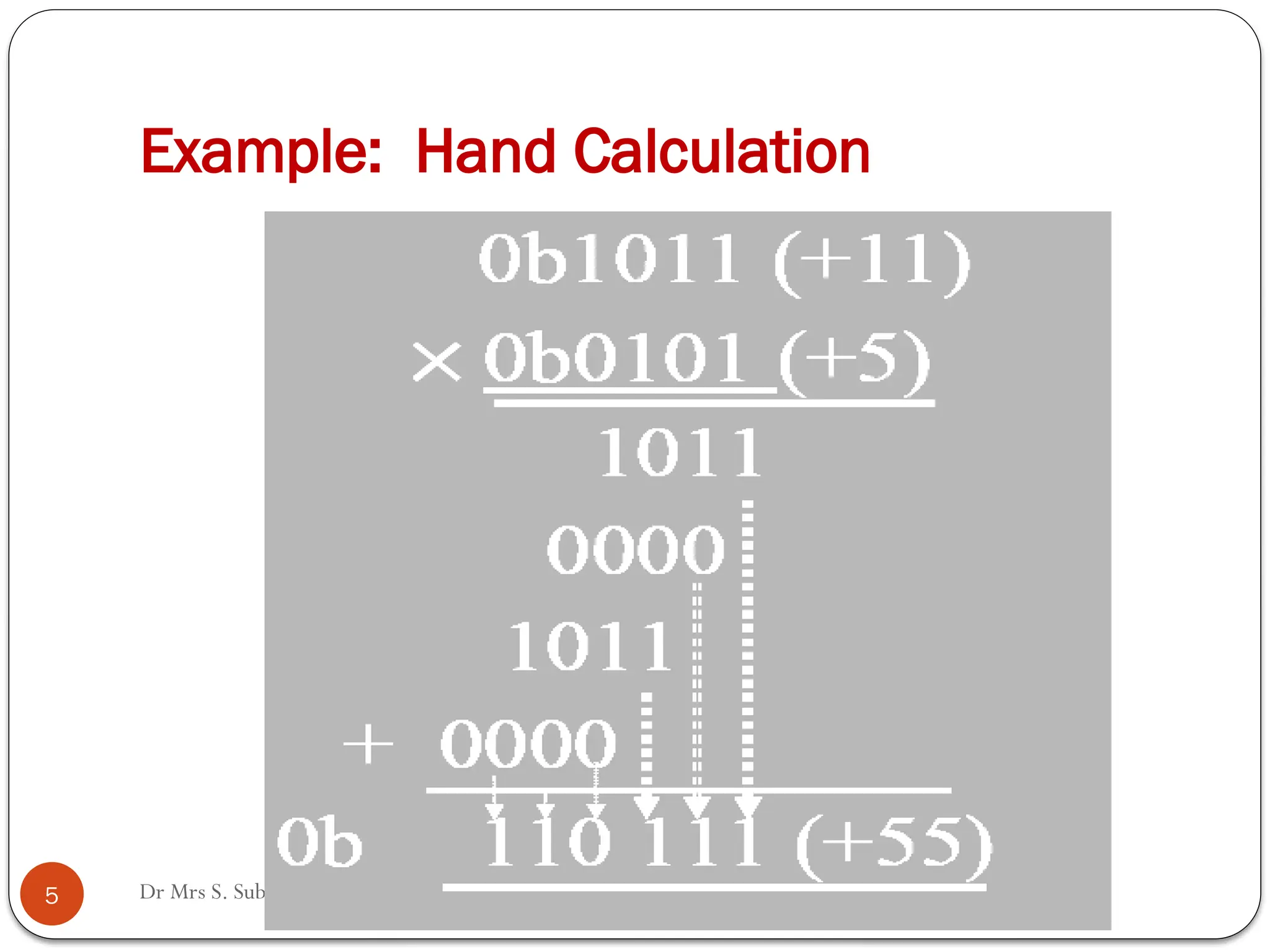
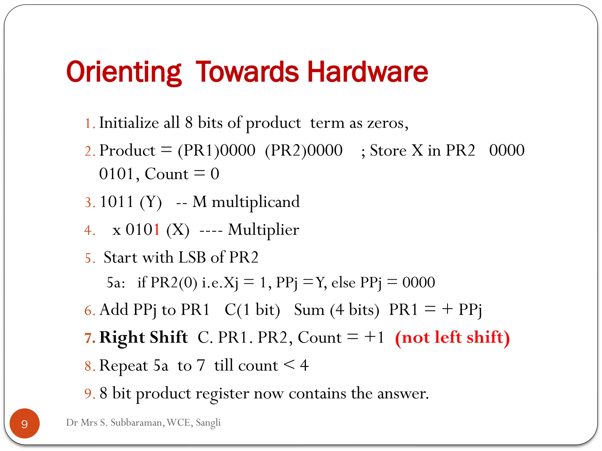
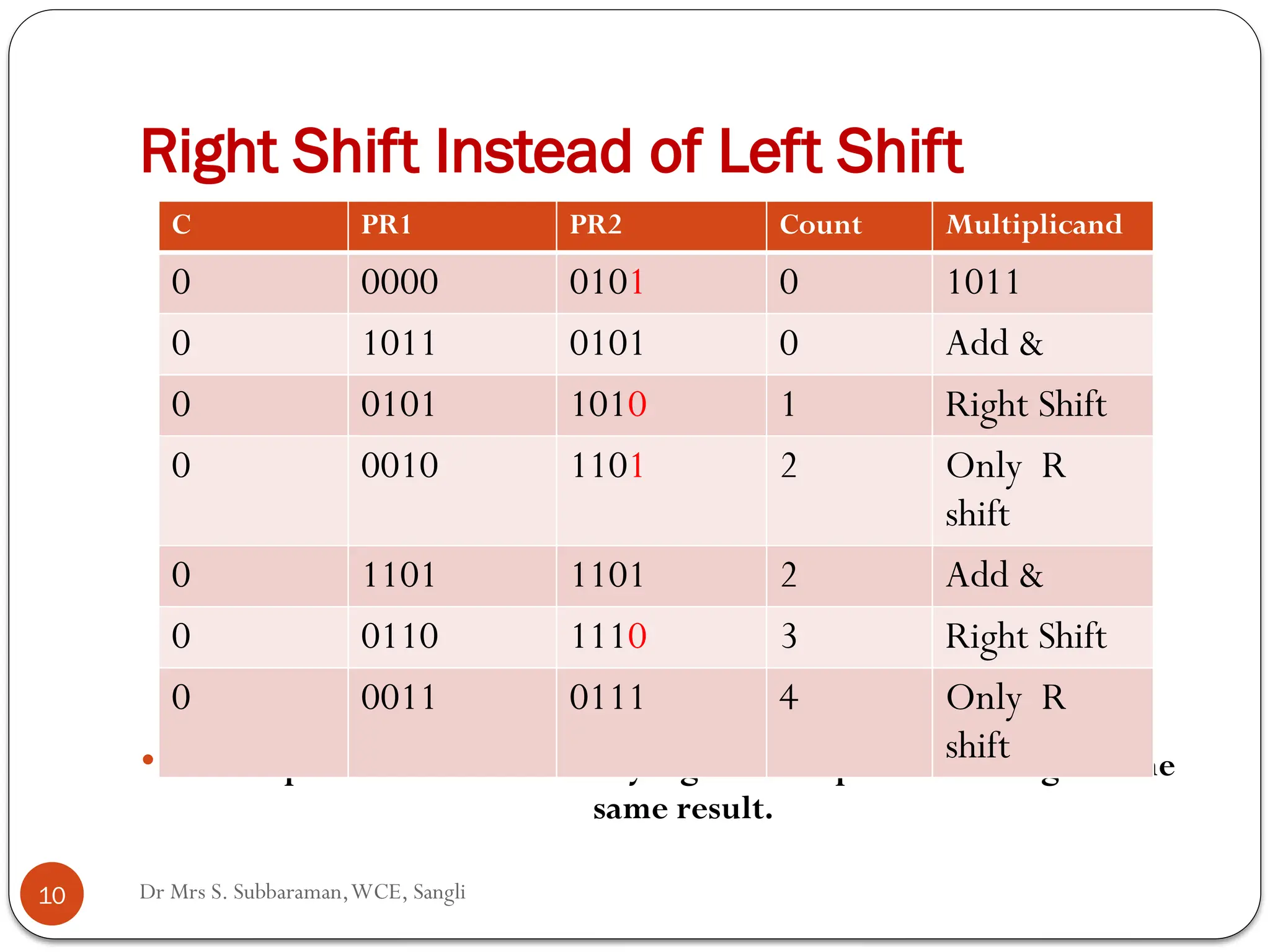
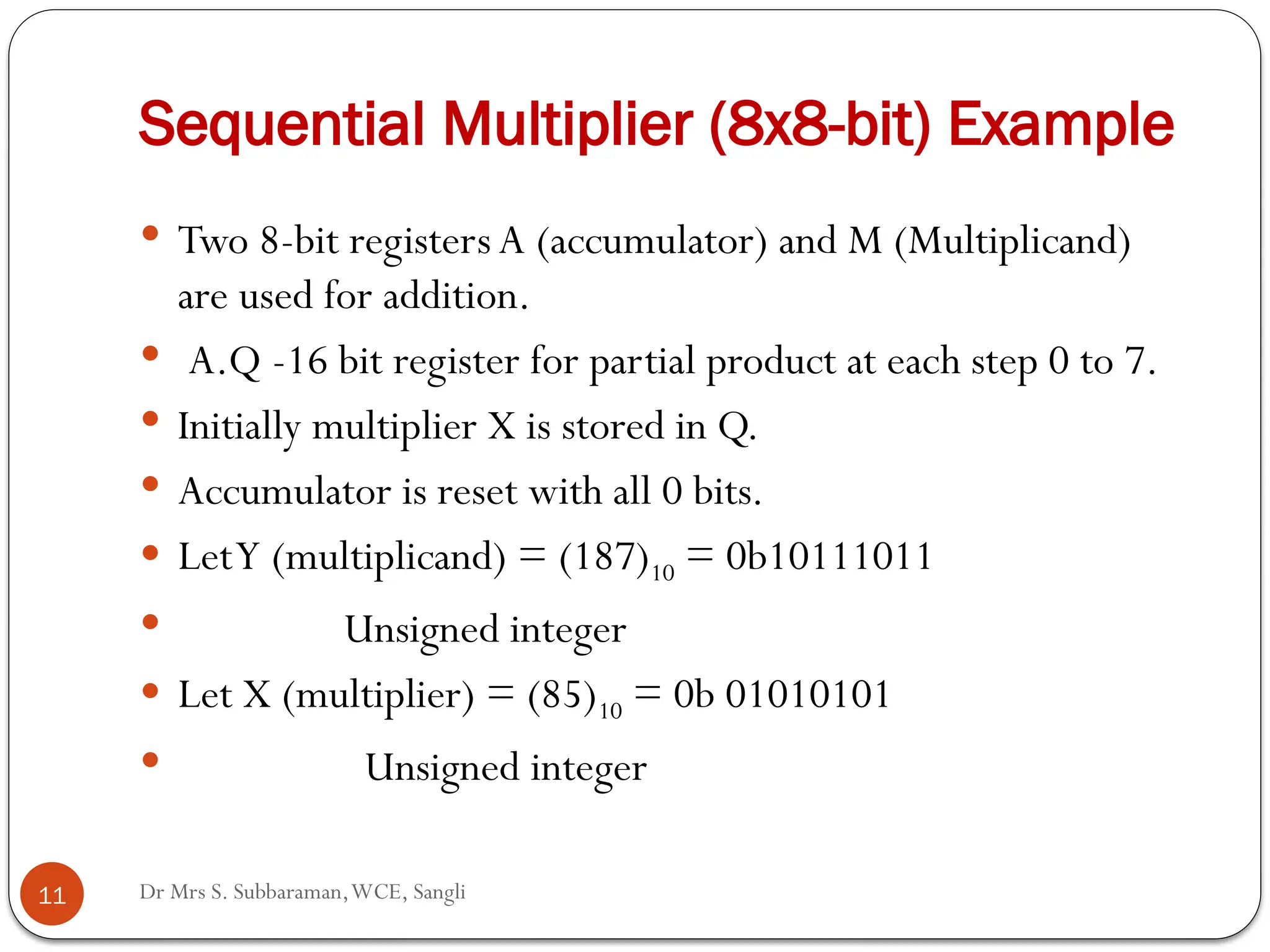
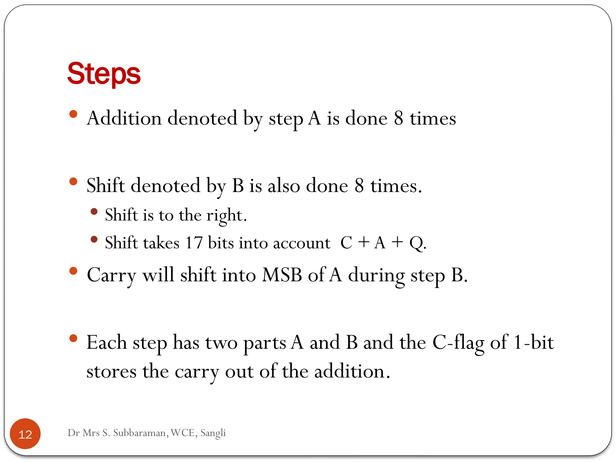
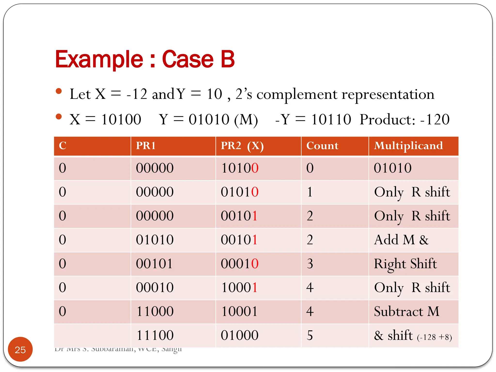
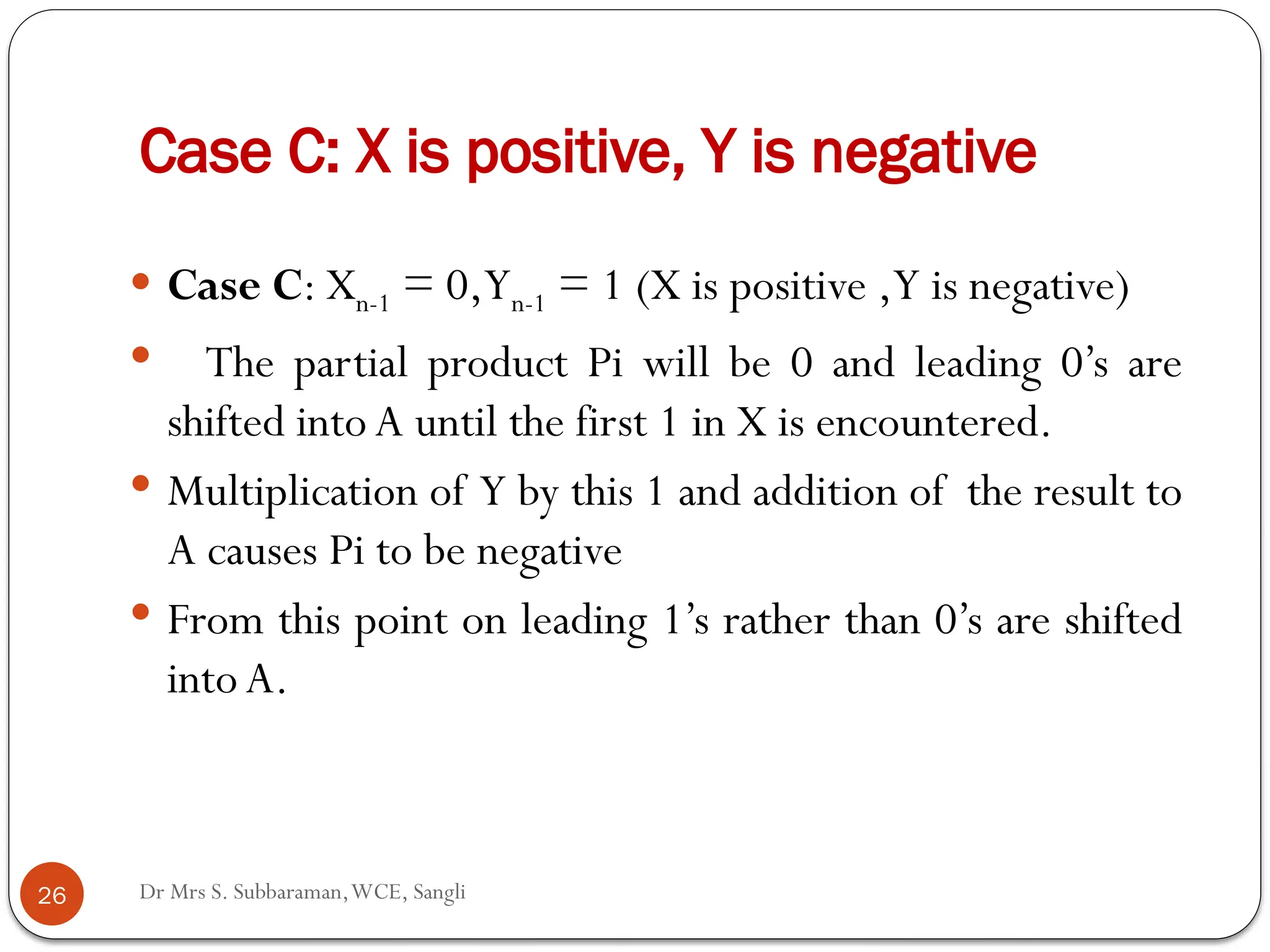
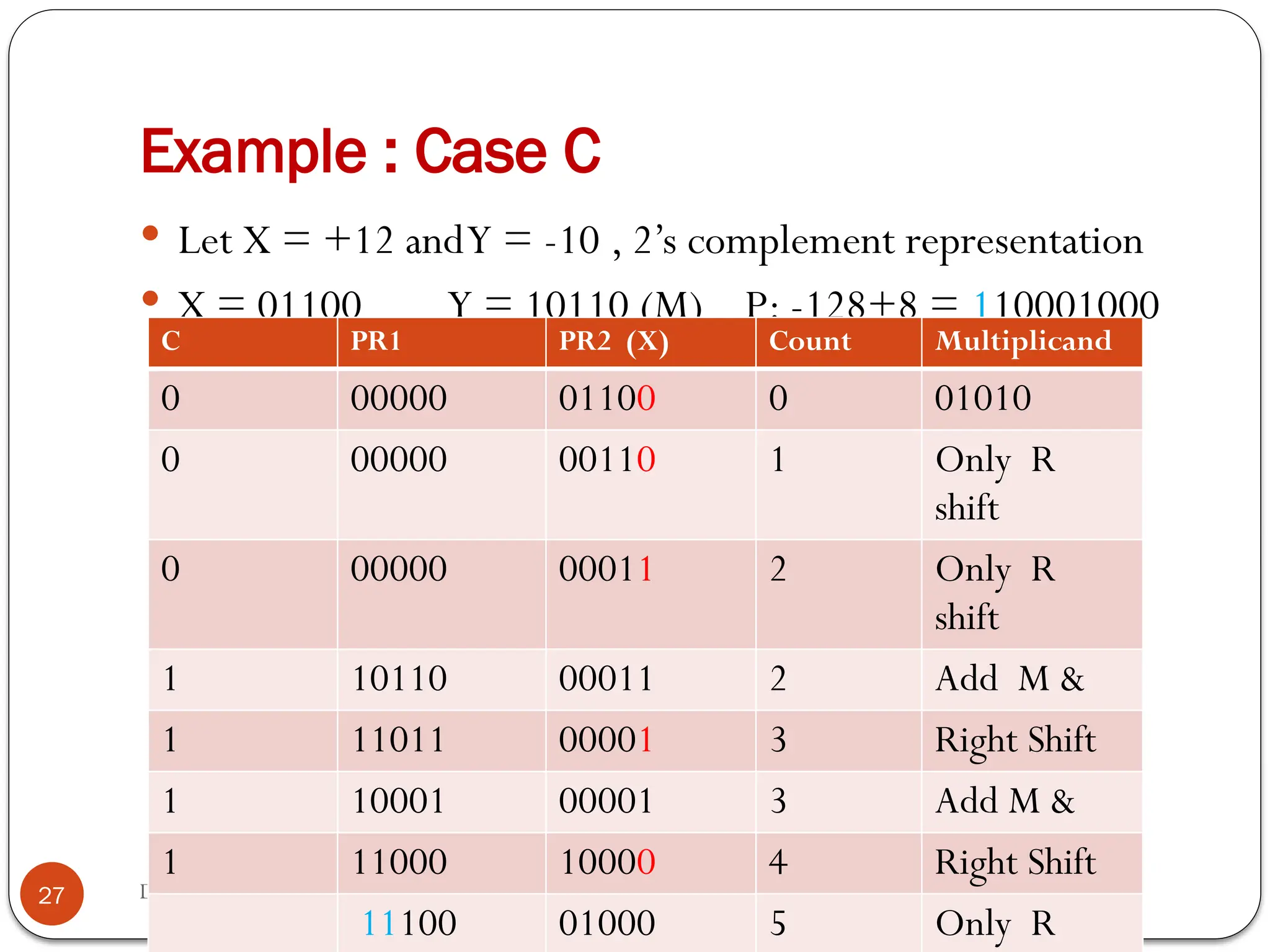
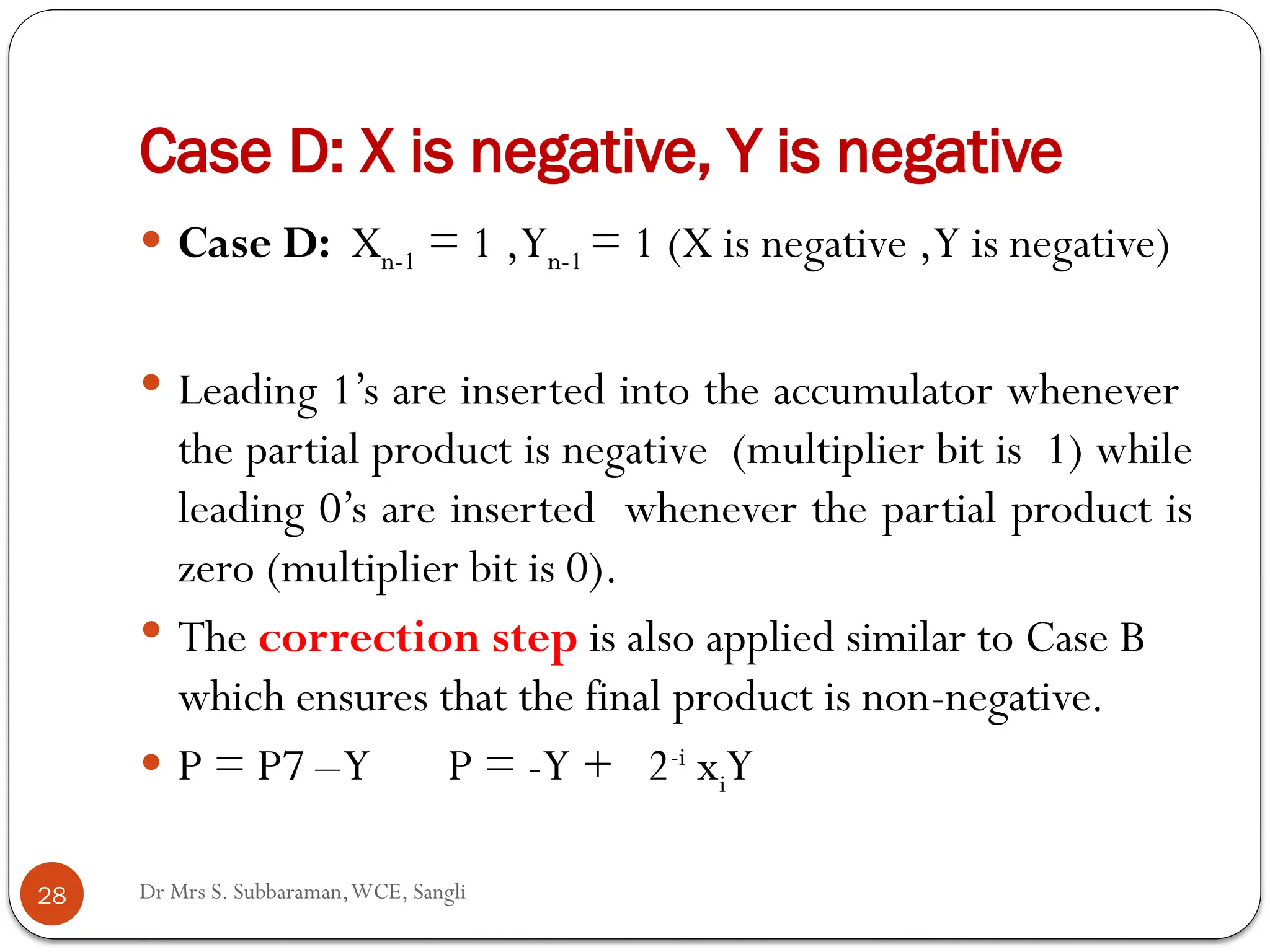
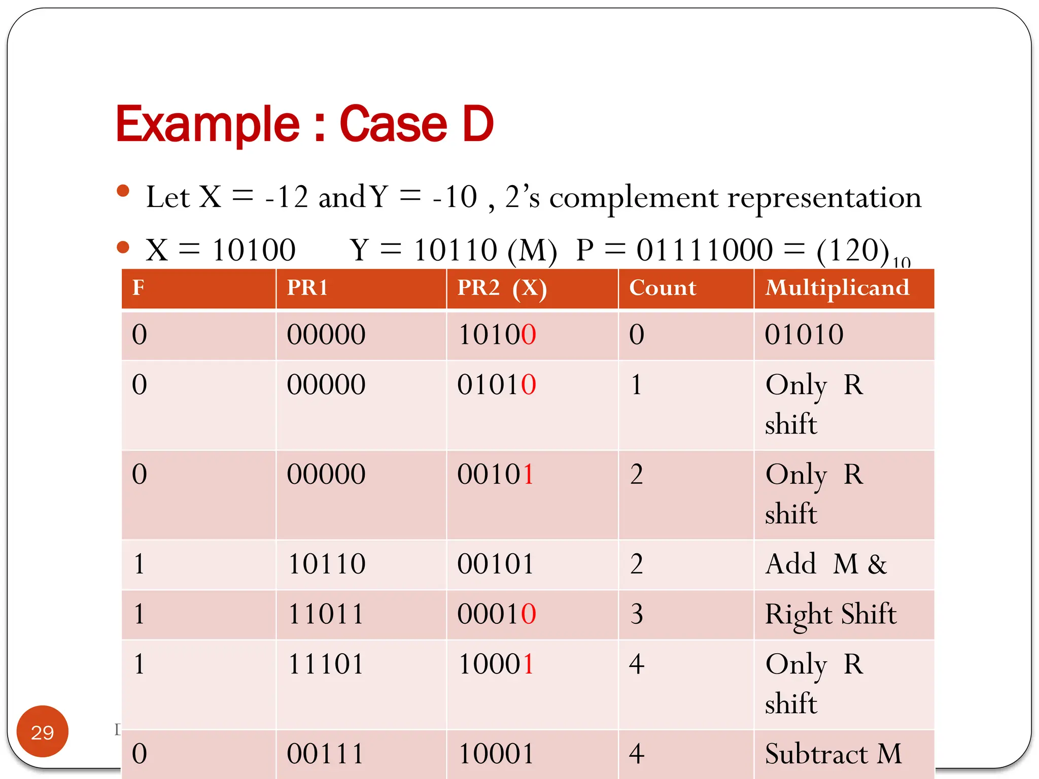
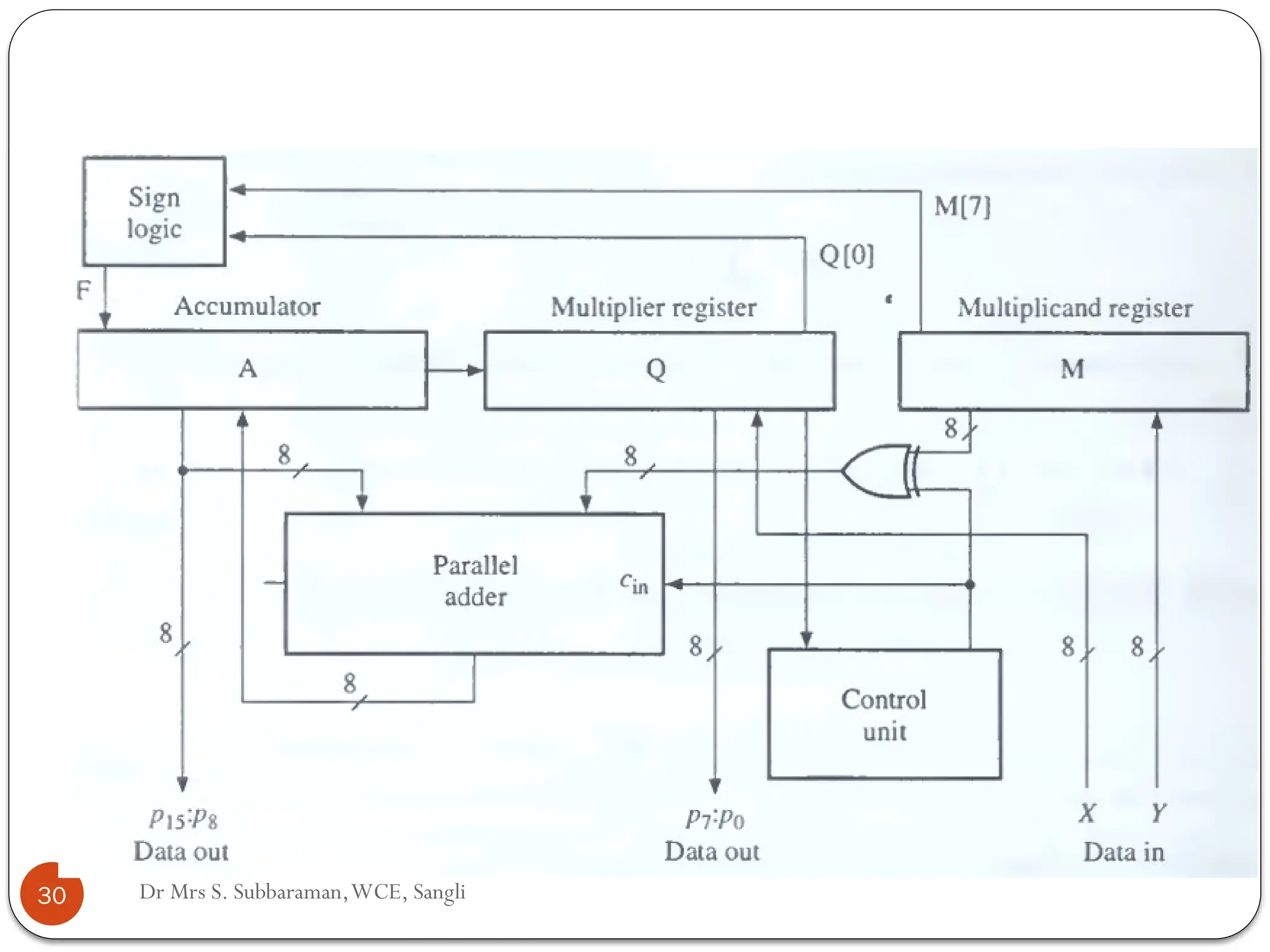
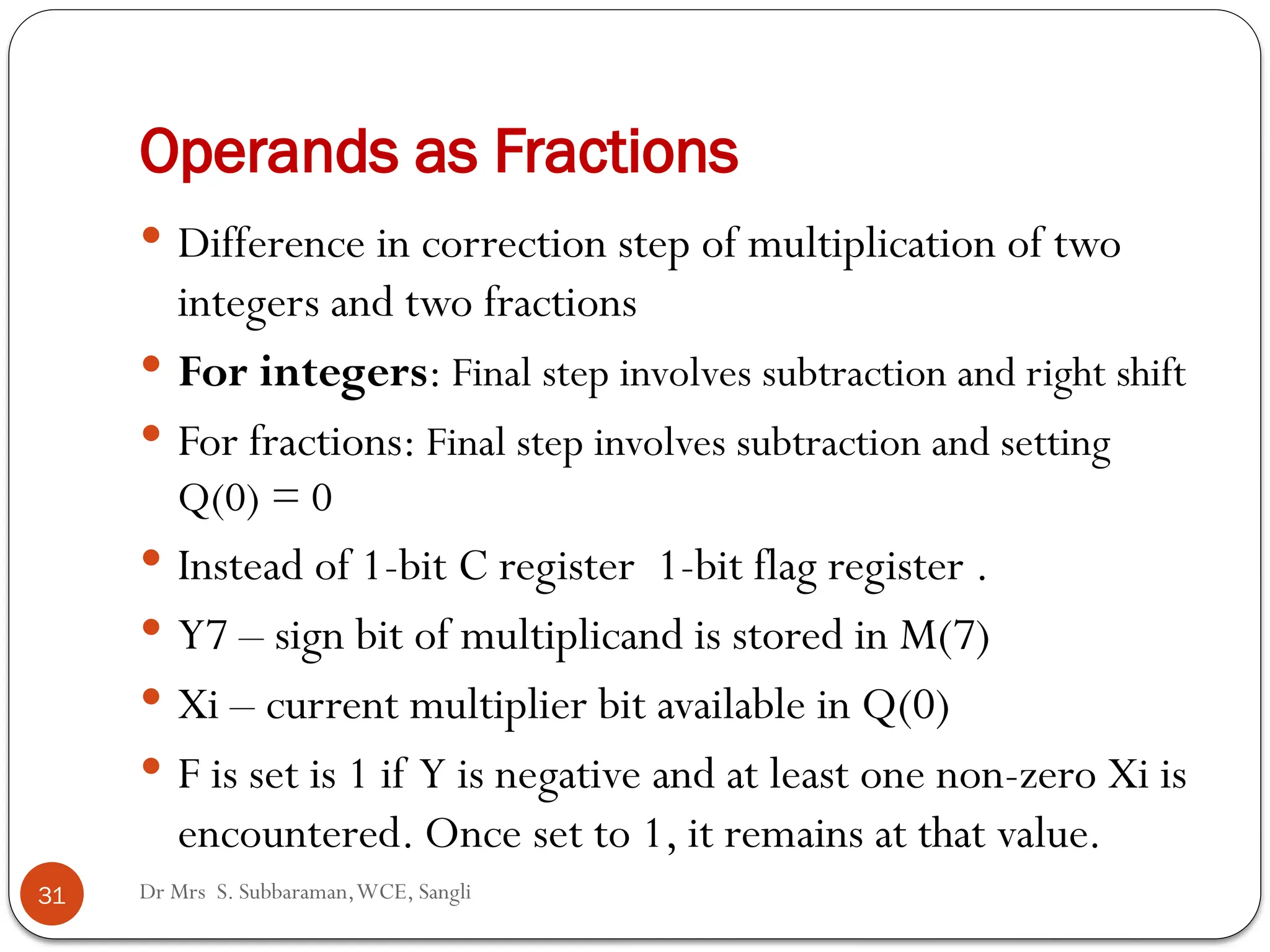
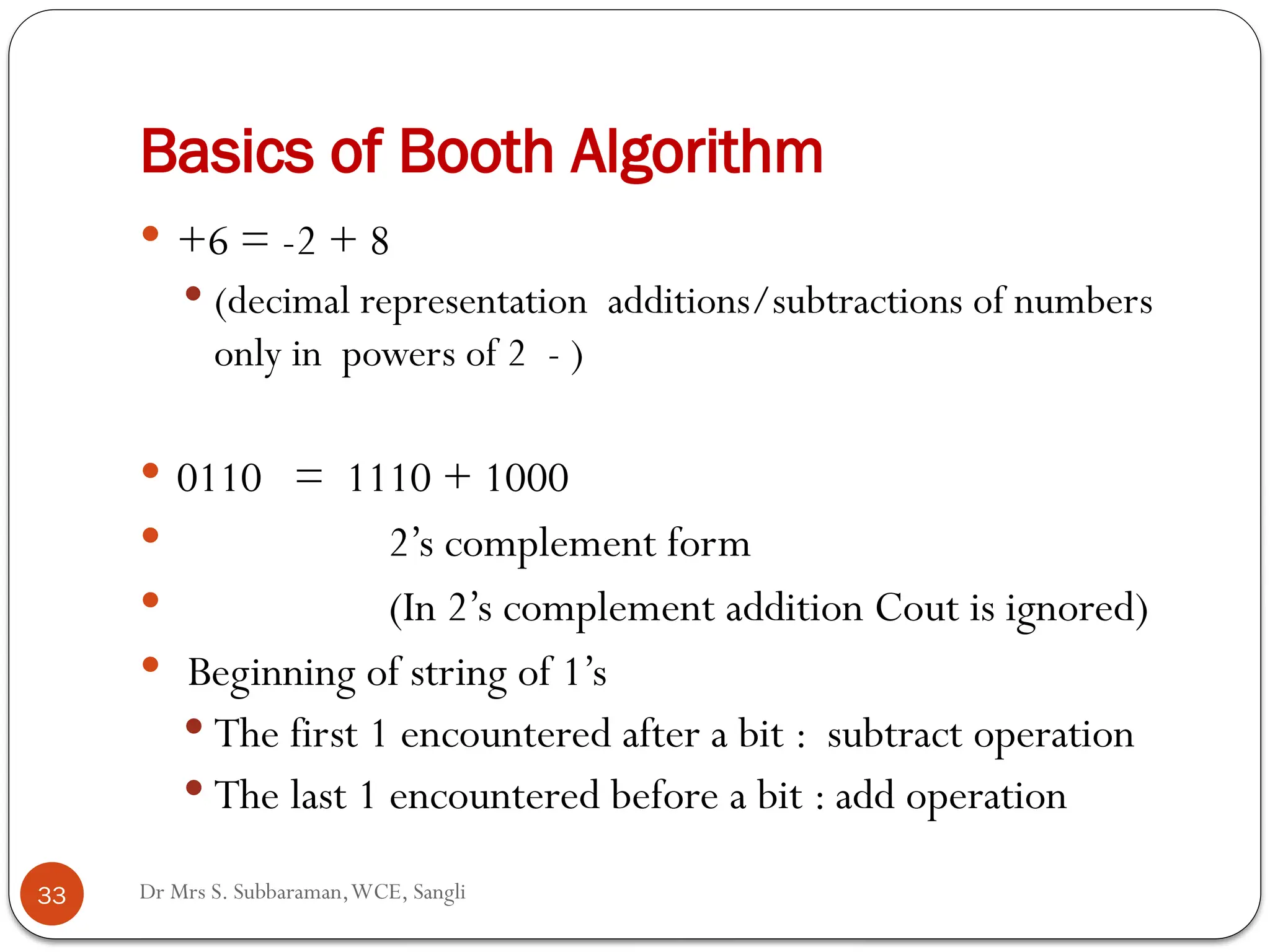
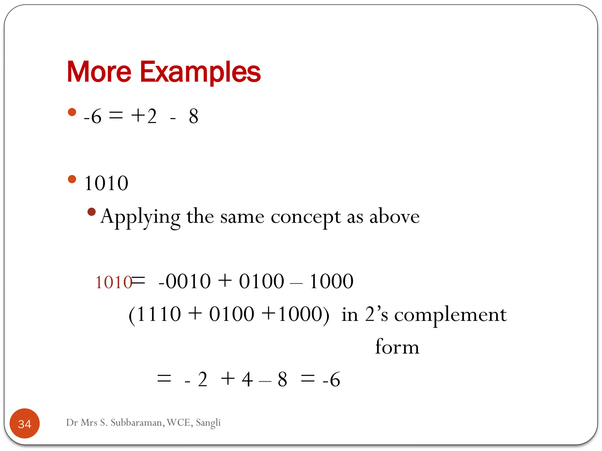
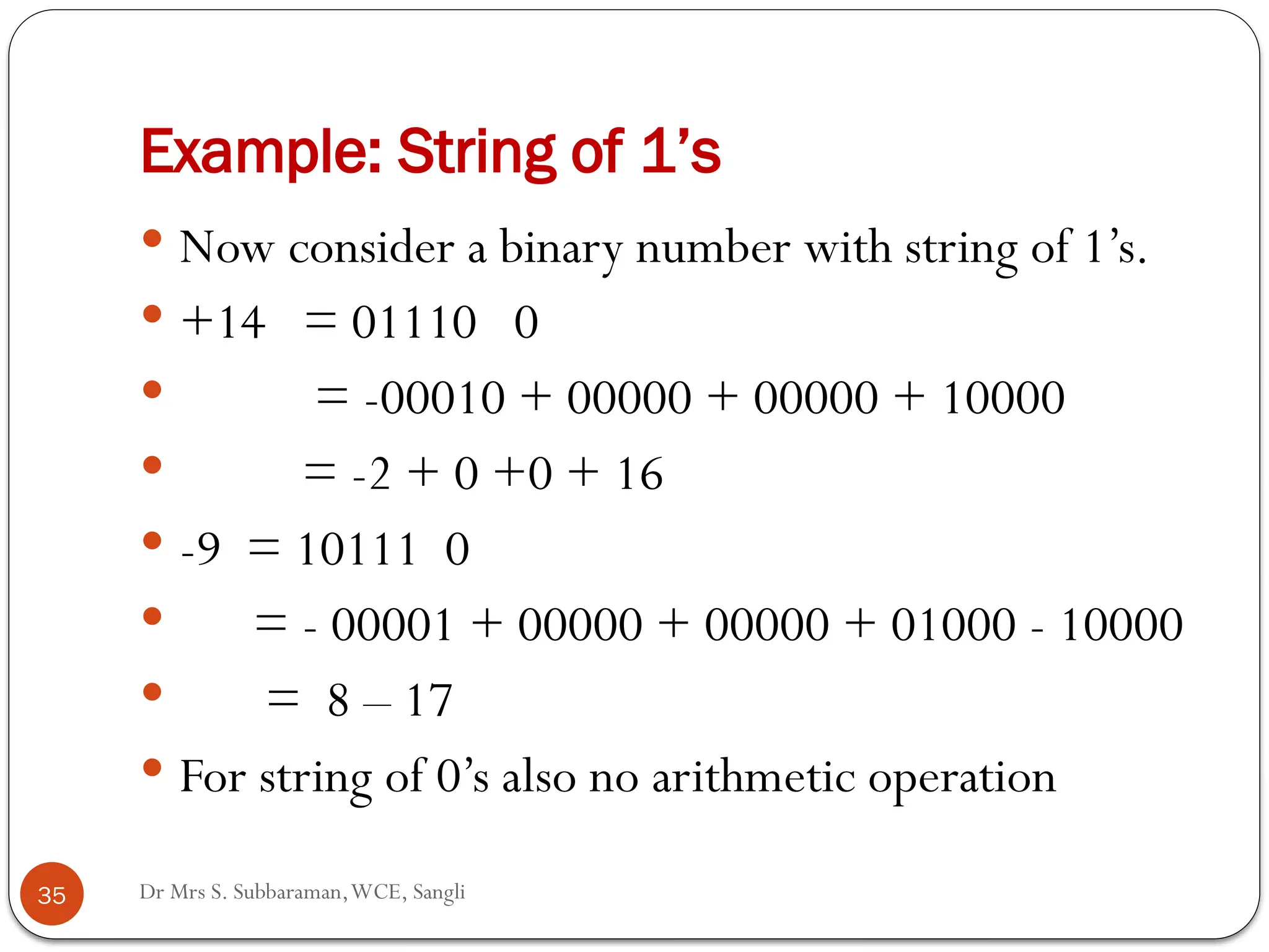
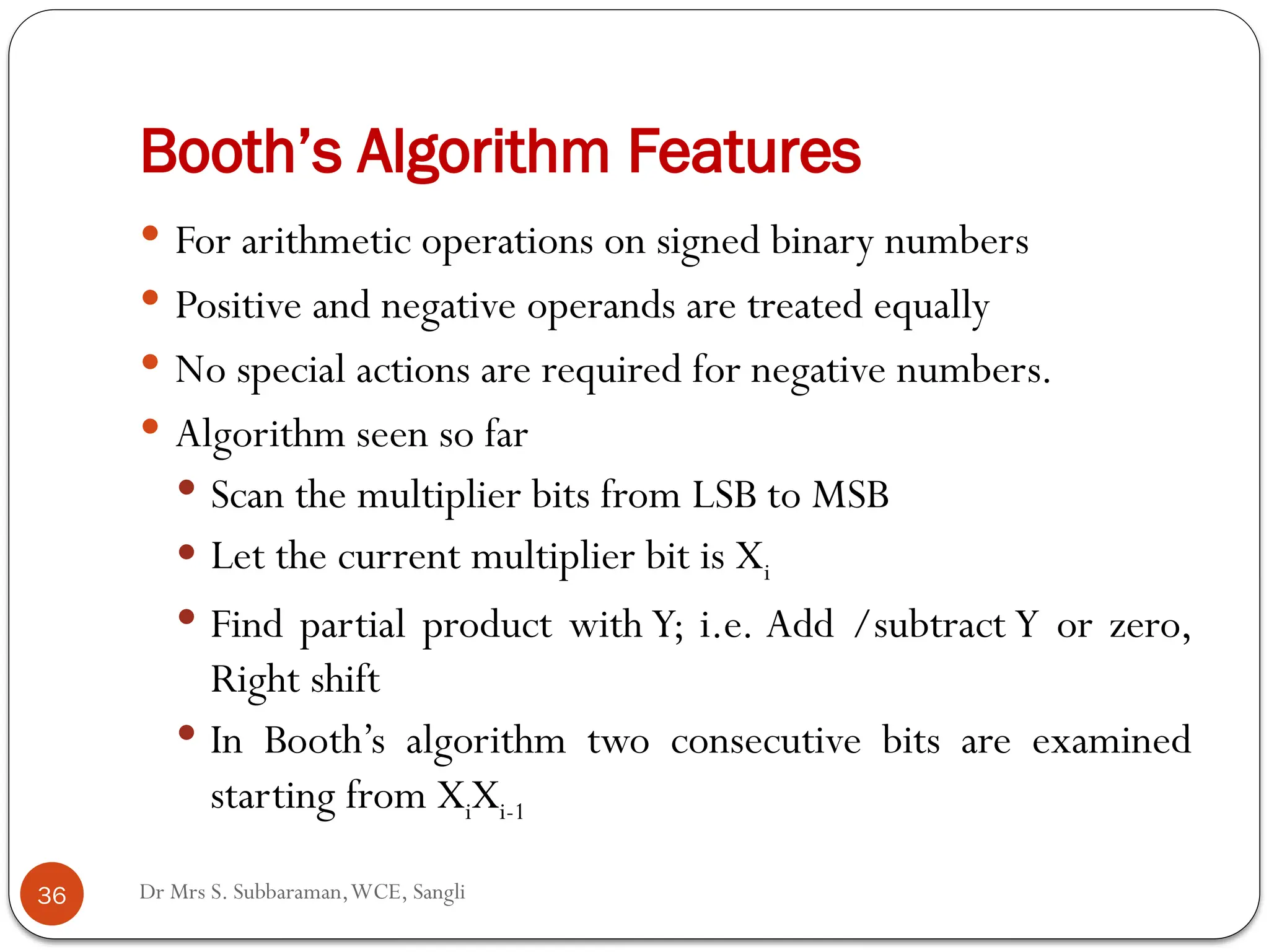
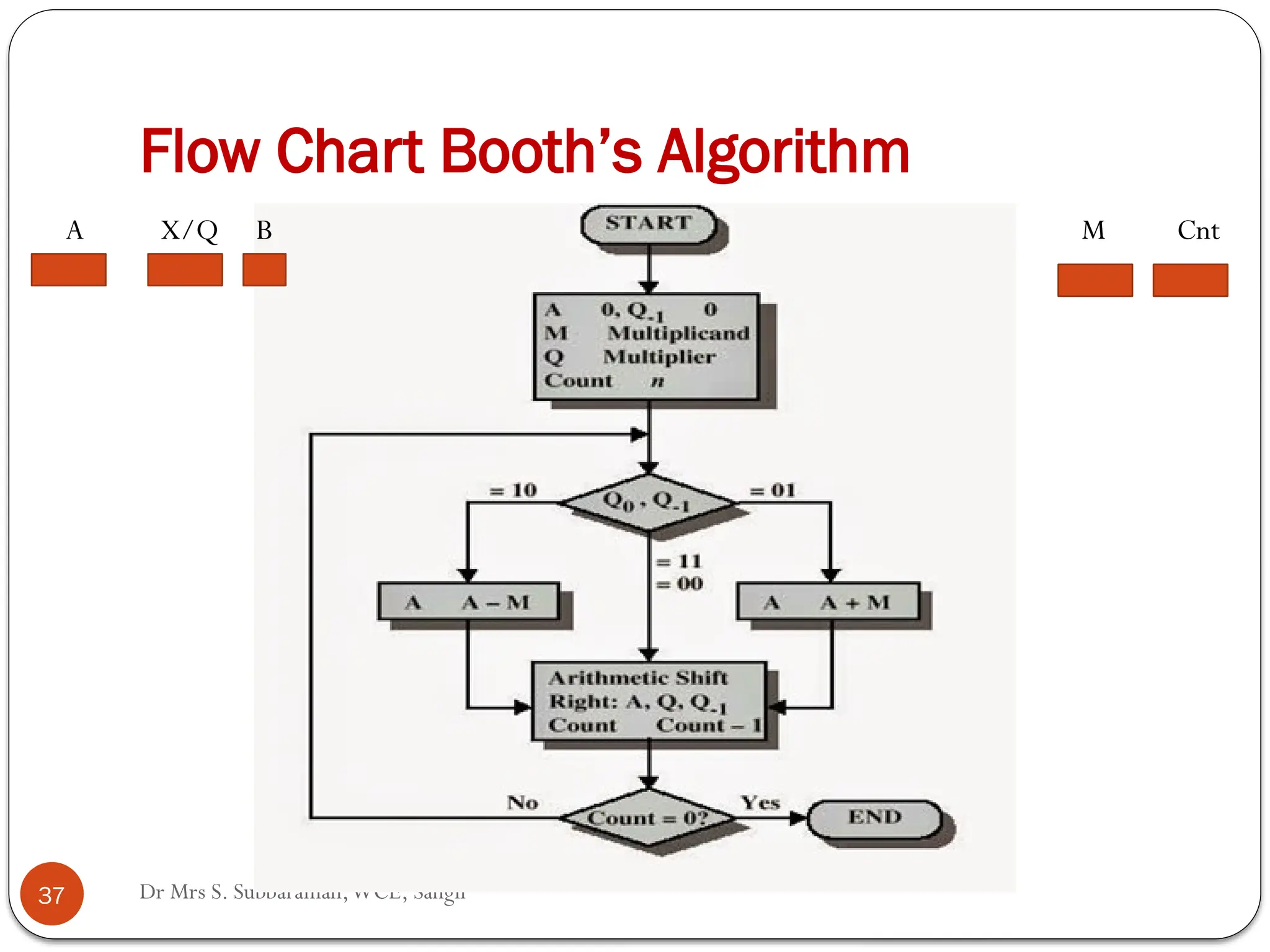
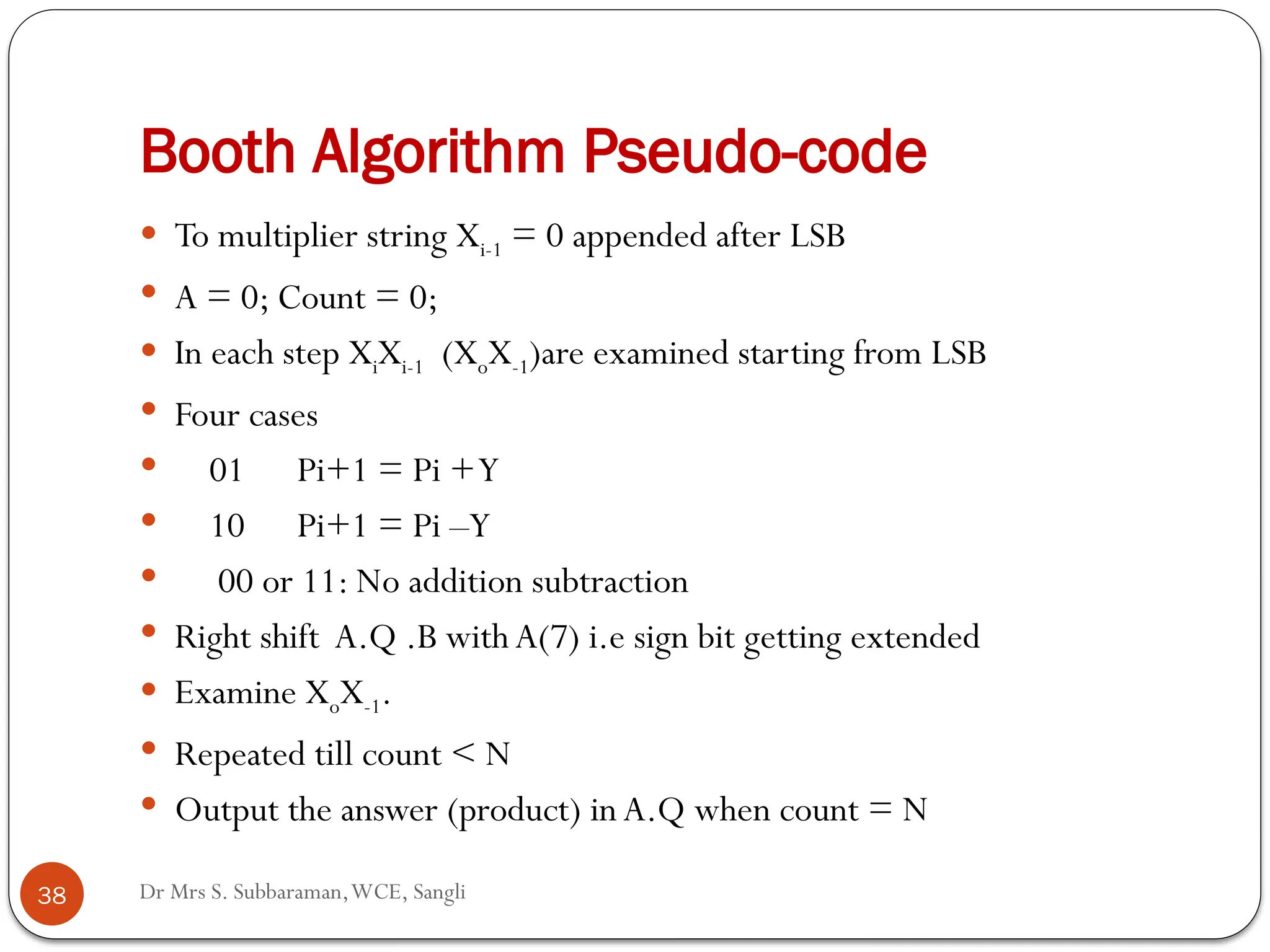
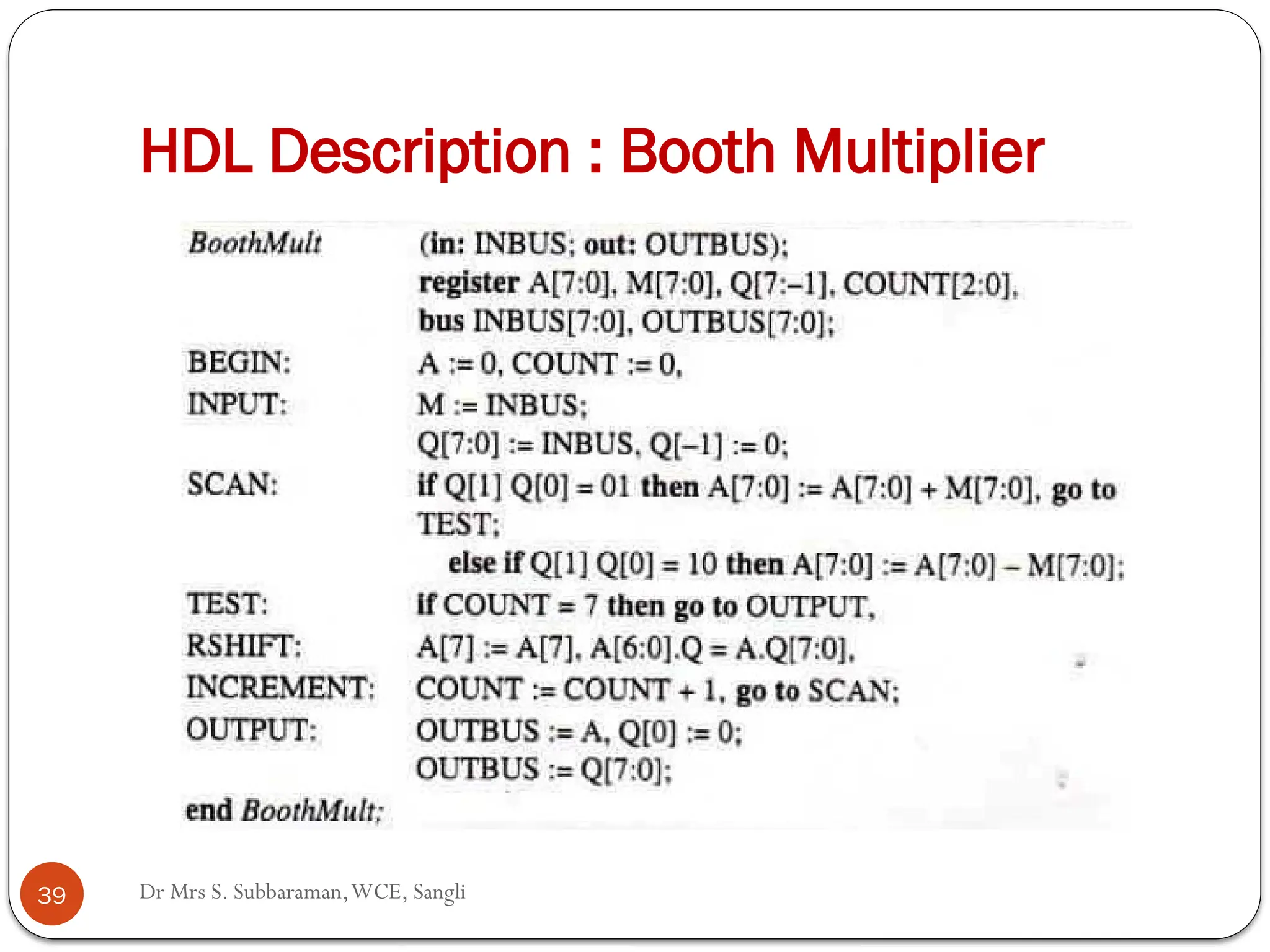
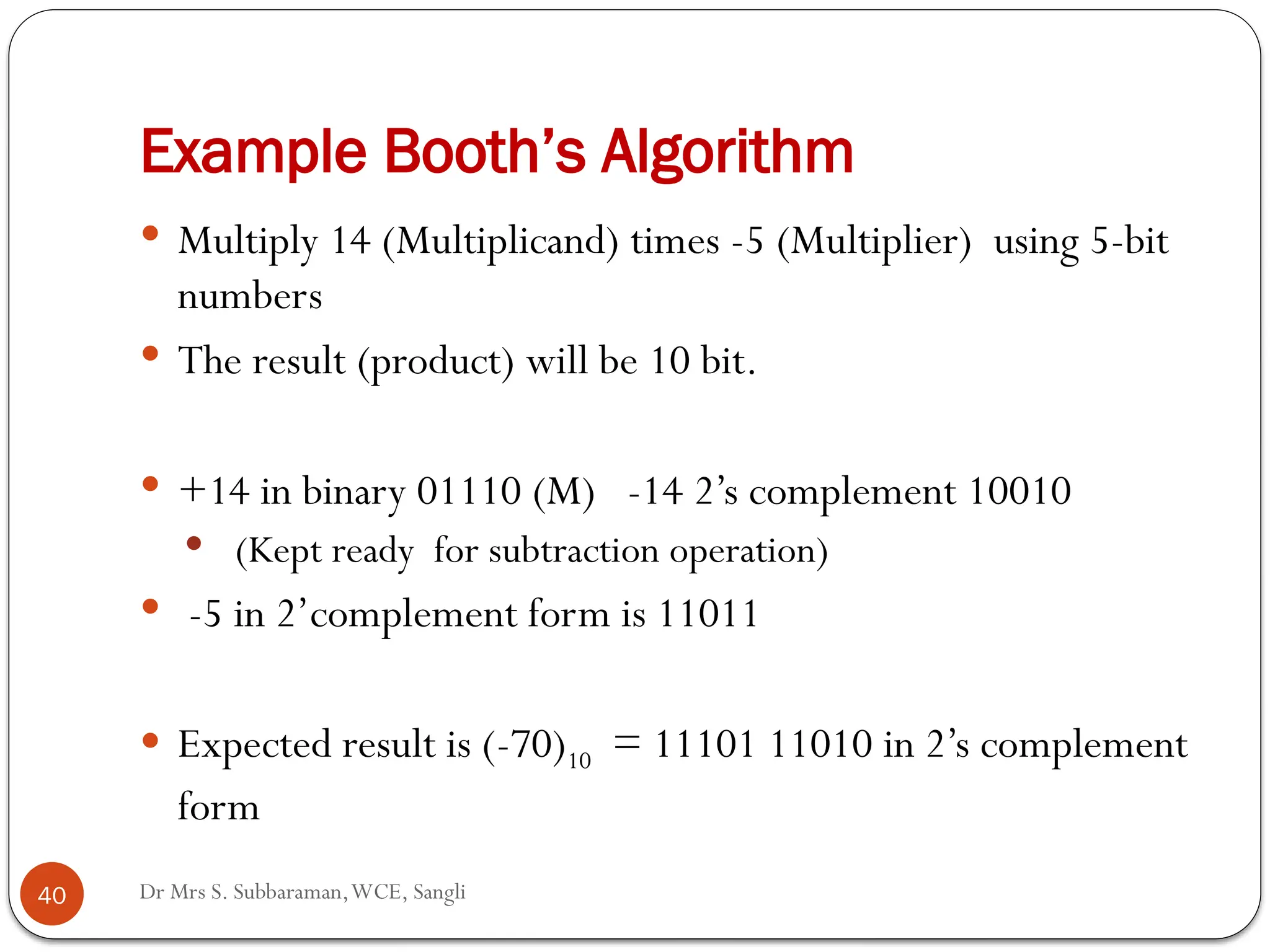
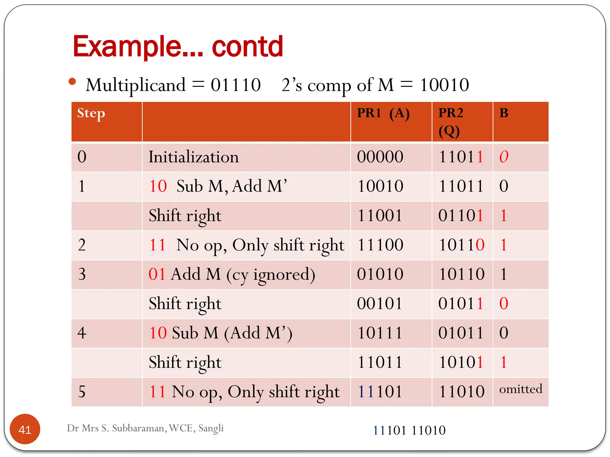
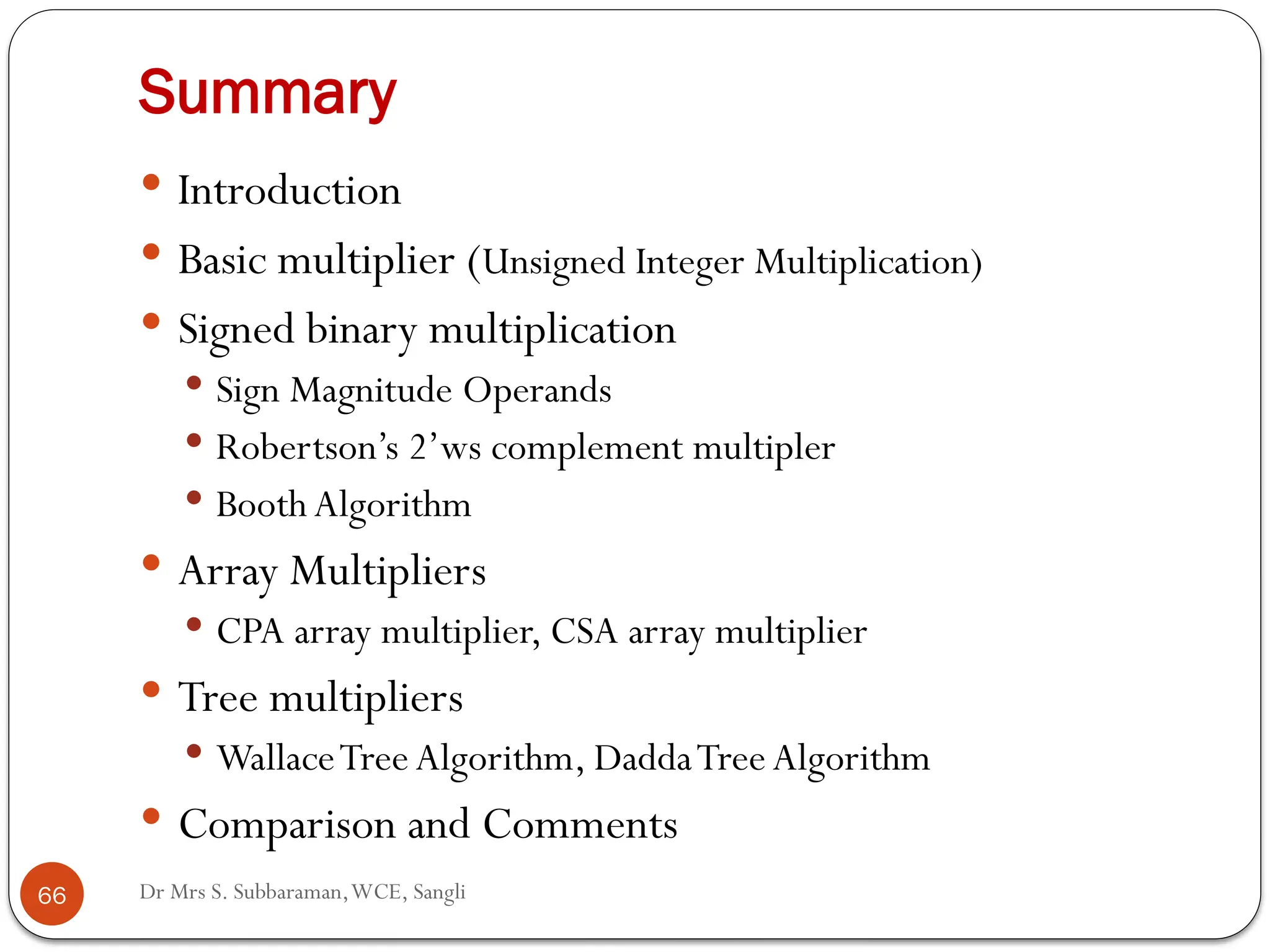
Dr Mrs S. Subbaraman
Walchand College of Engineering, Sangli
23rd
March 2017
@ KIT, Kolhapur
Digital Multipliers
Dr Mrs S. Subbaraman,WCE, Sangli
Organization
 Introduction
 Basic multiplier (Unsigned Integer Multiplication)
 Signed binary multiplication
 Sign Magnitude Operands
 Robertson’s 2’ws complement multiplier
 Booth Algorithm
 Array Multipliers
 CPA array multiplier, CSA array multiplier
 Tree multipliers
 WallaceTree Algorithm, DaddaTree Algorithm
 Comparison and Summary
2
Dr Mrs S. Subbaraman,WCE, Sangli
Introduction
 What are basic operations in processing the signal
(information) digitally?
 FT, FFT, DCT,
 Convolution, Correlation
 Filters (FIR, IIR)
 MAC operation
 Accumulator – adders
 Multiplier – repeated addition
 5 x 4 = 5 + 5 + 5 + 5
 Various approaches for unsigned and signed integers
3
Dr Mrs S. Subbaraman,WCE, Sangli
BASIC MULTIPLIER
ALGORITHM
UNSIGNED INTEGERS
4
Dr Mrs S. Subbaraman,WCE, Sangli
Example: Hand Calculation
5
Dr Mrs S. Subbaraman,WCE, Sangli
N-bit x N-bit Unsigned Multiplication
 Paper Pencil Method
 Handled in a similar way we multiply multi-digit decimal numbers
(512 x 327)
 Input : Multiplicand (Y) Multiplier (X)
 The multiplicand (Yn-1,Yn-2, ------Y0) is multiplied by each bit of
multiplier (X0, X1,----Xn-1) in N steps starting from X0.
 Each step output is called as partial product.
 The partial products are shifted one bit position to the left of previous
partial product with no shift to the first partial product of
multiplication of Y by LSB of X.
 All such shifted partial products are then added to get the final answer.
6
Dr Mrs S. Subbaraman,WCE, Sangli
Basic Algorithm
 Y (Multiplicand) Y3Y2Y1Y0 (i from 0 to (N-1))
 X (Multiplier) X3X2X1X0 (j from 0 to (N-1))
 Multiplication in binary is simplified by the fact that the resulting
multiplication bit is either 0 or the multiplicand itself (Y)
 P0 (Initial partial product) = all bits zeros
 For i in 0 to (N-1)
 for j 0 to (N-1)
 Pi +1 = Pi + Xj2i
Y Left shift operation similar to manual
calculation
 Machine implementation; Right shift operation with few
considerations.
7
Dr Mrs S. Subbaraman,WCE, Sangli
Orienting Towards Hardware
 How many registers we need? (3)
 Y register (Multiplicand) – 4 bit
 X register (Multiplier) – 4 bit
 P register - 8 bit
 X Y
 P
 For addition one of the registers is accumulator
 Can AX together be OK for P?
 A X
 1011 0101
 In place algorithm
8
Dr Mrs S. Subbaraman,WCE, Sangli
Orienting Towards Hardware
1. Initialize all 8 bits of product term as zeros,
2. Product = (PR1)0000 (PR2)0000 ; Store X in PR2 0000
0101, Count = 0
3. 1011 (Y) -- M multiplicand
4. x 0101 (X) ---- Multiplier
5. Start with LSB of PR2
5a: if PR2(0) i.e.Xj = 1, PPj =Y, else PPj = 0000
6. Add PPj to PR1 C(1 bit) Sum (4 bits) PR1 = + PPj
7. Right Shift C. PR1. PR2, Count = +1 (not left shift)
8. Repeat 5a to 7 till count < 4
9. 8 bit product register now contains the answer.
9
Dr Mrs S. Subbaraman,WCE, Sangli
Right Shift Instead of Left Shift
 (11 x 5 = 55 110111)
 Multiplication carried out by right shift operation also gives the
same result.
C PR1 PR2 Count Multiplicand
0 0000 0101 0 1011
0 1011 0101 0 Add &
0 0101 1010 1 Right Shift
0 0010 1101 2 Only R
shift
0 1101 1101 2 Add &
0 0110 1110 3 Right Shift
0 0011 0111 4 Only R
shift
10
Dr Mrs S. Subbaraman,WCE, Sangli
Sequential Multiplier (8x8-bit) Example
11
 Two 8-bit registers A (accumulator) and M (Multiplicand)
are used for addition.
 A.Q -16 bit register for partial product at each step 0 to 7.
 Initially multiplier X is stored in Q.
 Accumulator is reset with all 0 bits.
 LetY (multiplicand) = (187)10 = 0b10111011
 Unsigned integer
 Let X (multiplier) = (85)10 = 0b 01010101
 Unsigned integer
Dr Mrs S. Subbaraman,WCE, Sangli
Steps
12
 Addition denoted by stepA is done 8 times
 Shift denoted by B is also done 8 times.
 Shift is to the right.
 Shift takes 17 bits into account C + A + Q.
 Carry will shift into MSB of A during step B.
 Each step has two partsA and B and the C-flag of 1-bit
stores the carry out of the addition.
Dr Mrs S. Subbaraman,WCE, Sangli
Unsigned N x N bit Multiplier
MultiplicandY
Multiplier Q reg
Accumulator
N
N
13
Dr Mrs S. Subbaraman,WCE, Sangli
Example
14
Dr Mrs S. Subbaraman,WCE, Sangli
Example … contd.
15
Dr Mrs S. Subbaraman,WCE, Sangli
MULTIPLIER FOR
SIGNED INTEGER OPERANDS
16
Dr Mrs S. Subbaraman,WCE, Sangli
Multiplier: Signed Operands
 Representation:
 Sign magnitude representation
 MSB (Xn-1) is sign : 0 for positive
1 for negative
 Rest of the bits represent magnitude
 Range (∑2i
xi i from 0 to (n-2) ) 8 bit : -127 to + 127
 Floating point number representation S (1) E(8) M (23)
 2’s Complement form
 MSB is sign as above
 Rest of the bits represent magnitude.
 Positive number : No difference
 Negative numbers : - 2n-1
xn-1 + ∑ 2i
xi i from 0 to (n-2)
17
Dr Mrs S. Subbaraman,WCE, Sangli
Multiplier (Sign Magnitude Operands)
 Same hardware as for unsigned multiplier
 Care for sign bit
 MSB of bothY (M) and X (Q) is a sign bit
 Rest of the bits represent the magnitude.
 Treat sign and magnitude separately
 (N-1) x (N-1) multiplier
 Result in (N-1) steps; Product term has now (2N-2) terms
 Sign of product term (MSB) = XOR of MSBs of Y and X
 Append the sign bit to 2(N-2) product bits.
18
Dr Mrs S. Subbaraman,WCE, Sangli
Example
19
 -14 x +9
 - 14 in sign magnitude form 11110
 +9 01001
 Initially ignore sign. Consider only the magnitudes.
 Apply same method of multiplication of unsigned integers.
 1110 x 1001 = 1111110 (126)10
 Hardware implementation same with additional sign logic
 XORing of most significant bits of two operands gives the
sign bit of the product.
Signed N x N bit Multiplier
MultiplicandY
Multiplier
Accumulator
N
N
20 Dr Mrs S. Subbaraman,WCE, Sangli
X7 Y7
P(15) P(14-8)
XOR
Dr Mrs S. Subbaraman,WCE, Sangli
ROBERTSON’S
ALGORITHM
21
Dr Mrs S. Subbaraman,WCE, Sangli
Multiplier (2’ Complement Operands)
 Robertson’s Algorithm (2’s complement Multiplier)
 Signed Integer Multiplication
 Consider both the operands with sign bit. (2’s complement
form)
 X = -2n-1
xn-1 + 2i
xi
 Depending upon the sign of the two operands, there are 4 cases.
 Both operands positive
 Both operands negative
 Multiplier is positive, Multiplicand is negative
 Multiplier is negative, Multiplicand is positive
22
Dr Mrs S. Subbaraman,WCE, Sangli
Case A : X, Y positive
 Case A:
 Both X,Y and are positive (X7 =Y7 = 0)
 Multiplication is similar to that of two unsigned numbers
 Product P is computed as series of add and shift
operations
Pi = Pi + XjY
Pi+1 = 2-1
Pi
 Here all partial products are non-negative.
 Hence leading zeros are introduced during right shift
operation,
23
Dr Mrs S. Subbaraman,WCE, Sangli
Case B: X is negative, Y is positive
 Case B: Xn-1 = 1 Yn-1 = 0
 X is negative andY is positive
 In this case partial product is always positive till the
sign bit Xn-1 is not encountered
 In the final step, referred as correction step,
subtraction is performed followed by right shift
operation.
 (A –Y =A + 2’s complementY …. Sign extension.
 P = P7 –Y
24
Dr Mrs S. Subbaraman,WCE, Sangli
Example : Case B
 Let X = -12 andY = 10 , 2’s complement representation
 X = 10100 Y = 01010 (M) -Y = 10110 Product: -120
C PR1 PR2 (X) Count Multiplicand
0 00000 10100 0 01010
0 00000 01010 1 Only R shift
0 00000 00101 2 Only R shift
0 01010 00101 2 Add M &
0 00101 00010 3 Right Shift
0 00010 10001 4 Only R shift
0 11000 10001 4 Subtract M
11100 01000 5 & shift (-128 +8)
25
Dr Mrs S. Subbaraman,WCE, Sangli
Case C: X is positive, Y is negative
 Case C: Xn-1 = 0,Yn-1 = 1 (X is positive ,Y is negative)
 The partial product Pi will be 0 and leading 0’s are
shifted into A until the first 1 in X is encountered.
 Multiplication of Y by this 1 and addition of the result to
A causes Pi to be negative
 From this point on leading 1’s rather than 0’s are shifted
intoA.
26
Dr Mrs S. Subbaraman,WCE, Sangli
Example : Case C
 Let X = +12 andY = -10 , 2’s complement representation
 X = 01100 Y = 10110 (M) P: -128+8 = 110001000
C PR1 PR2 (X) Count Multiplicand
0 00000 01100 0 01010
0 00000 00110 1 Only R
shift
0 00000 00011 2 Only R
shift
1 10110 00011 2 Add M &
1 11011 00001 3 Right Shift
1 10001 00001 3 Add M &
1 11000 10000 4 Right Shift
11100 01000 5 Only R
27
Dr Mrs S. Subbaraman,WCE, Sangli
Case D: X is negative, Y is negative
 Case D: Xn-1 = 1 ,Yn-1 = 1 (X is negative ,Y is negative)
 Leading 1’s are inserted into the accumulator whenever
the partial product is negative (multiplier bit is 1) while
leading 0’s are inserted whenever the partial product is
zero (multiplier bit is 0).
 The correction step is also applied similar to Case B
which ensures that the final product is non-negative.
 P = P7 –Y P = -Y + 2-i
xiY
28
Dr Mrs S. Subbaraman,WCE, Sangli
Example : Case D
 Let X = -12 andY = -10 , 2’s complement representation
 X = 10100 Y = 10110 (M) P = 01111000 = (120)10
F PR1 PR2 (X) Count Multiplicand
0 00000 10100 0 01010
0 00000 01010 1 Only R
shift
0 00000 00101 2 Only R
shift
1 10110 00101 2 Add M &
1 11011 00010 3 Right Shift
1 11101 10001 4 Only R
shift
0 00111 10001 4 Subtract M
29
Dr Mrs S. Subbaraman,WCE, Sangli
30
Operands as Fractions
 Difference in correction step of multiplication of two
integers and two fractions
 For integers: Final step involves subtraction and right shift
 For fractions: Final step involves subtraction and setting
Q(0) = 0
 Instead of 1-bit C register 1-bit flag register .
 Y7 – sign bit of multiplicand is stored in M(7)
 Xi – current multiplier bit available in Q(0)
 F is set is 1 if Y is negative and at least one non-zero Xi is
encountered. Once set to 1, it remains at that value.
31 Dr Mrs S. Subbaraman,WCE, Sangli
Dr Mrs S. Subbaraman,WCE, Sangli
BOOTH’S ALGORITHM
32
Dr Mrs S. Subbaraman,WCE, Sangli
Basics of Booth Algorithm
 +6 = -2 + 8
 (decimal representation additions/subtractions of numbers
only in powers of 2 - )
 0110 = 1110 + 1000
 2’s complement form
 (In 2’s complement addition Cout is ignored)
 Beginning of string of 1’s
 The first 1 encountered after a bit : subtract operation
 The last 1 encountered before a bit : add operation
33
Dr Mrs S. Subbaraman,WCE, Sangli
More Examples
 -6 = +2 - 8
 1010
Applying the same concept as above
1010= -0010 + 0100 – 1000
(1110 + 0100 +1000) in 2’s complement
form
= - 2 + 4 – 8 = -6
34
Dr Mrs S. Subbaraman,WCE, Sangli
Example: String of 1’s
 Now consider a binary number with string of 1’s.
 +14 = 01110 0
 = -00010 + 00000 + 00000 + 10000
 = -2 + 0 +0 + 16
 -9 = 10111 0
 = - 00001 + 00000 + 00000 + 01000 - 10000
 = 8 – 17
 For string of 0’s also no arithmetic operation
35
Dr Mrs S. Subbaraman,WCE, Sangli
Booth’s Algorithm Features
 For arithmetic operations on signed binary numbers
 Positive and negative operands are treated equally
 No special actions are required for negative numbers.
 Algorithm seen so far
 Scan the multiplier bits from LSB to MSB
 Let the current multiplier bit is Xi
 Find partial product with Y; i.e. Add /subtract Y or zero,
Right shift
 In Booth’s algorithm two consecutive bits are examined
starting from XiXi-1
36
Dr Mrs S. Subbaraman,WCE, Sangli
Flow Chart Booth’s Algorithm
A X/Q M Cnt
B
37
Booth Algorithm Pseudo-code
 To multiplier string Xi-1 = 0 appended after LSB
 A = 0; Count = 0;
 In each step XiXi-1 (XoX-1)are examined starting from LSB
 Four cases
 01 Pi+1 = Pi +Y
 10 Pi+1 = Pi –Y
 00 or 11: No addition subtraction
 Right shift A.Q .B with A(7) i.e sign bit getting extended
 Examine XoX-1.
 Repeated till count < N
 Output the answer (product) in A.Q when count = N
38 Dr Mrs S. Subbaraman,WCE, Sangli
Dr Mrs S. Subbaraman,WCE, Sangli
HDL Description : Booth Multiplier
39
Dr Mrs S. Subbaraman,WCE, Sangli
Example Booth’s Algorithm
40
 Multiply 14 (Multiplicand) times -5 (Multiplier) using 5-bit
numbers
 The result (product) will be 10 bit.
 +14 in binary 01110 (M) -14 2’s complement 10010
 (Kept ready for subtraction operation)
 -5 in 2’complement form is 11011
 Expected result is (-70)10 = 11101 11010 in 2’s complement
form
Dr Mrs S. Subbaraman,WCE, Sangli
Example… contd
41
 Multiplicand = 01110 2’s comp of M = 10010
Step PR1 (A) PR2
(Q)
B
0 Initialization 00000 11011 0
1 10 Sub M,Add M’ 10010 11011 0
Shift right 11001 01101 1
2 11 No op, Only shift right 11100 10110 1
3 01 Add M (cy ignored) 01010 10110 1
Shift right 00101 01011 0
4 10 Sub M (Add M’) 10111 01011 0
Shift right 11011 10101 1
5 11 No op, Only shift right 11101 11010 omitted
11101 11010
Dr Mrs S. Subbaraman,WCE, Sangli
Advantages of Booth Multiplier
 Advantages:
 Takes care of both positive and negative operands
 No final step as correction step is required.
 Faster in case of multiplier with running string of 1’s or
0’s.
 Modified Booth algorithm takes action by observing 3
bits (Xi+1XiXi_1) and is faster.
 Disadvantage:
 Operand dependent.
 Worst case delay same as that for Robertson’s multiplier
42
Dr Mrs S. Subbaraman,WCE, Sangli
ARRAY MULTIPLIERS
43
• Regular structures
•Appropriate architecture for
physical level implementation
•Easily scalable
Dr Mrs S. Subbaraman,WCE, Sangli
Array Multiplier
 Combinational Array Multipliers
 Can be upgraded to pipelined architectures
 Sup X andY are unsigned integers
 X = xn-1xn-2….x1xo
 Y = yn-1yn-2-----y1y0
 P = X xY
 = ∑2i
xiY (i = 0 to n-1)
 = ∑2i
∑xiyj2j
for all i and j from 0 to n-1
 xiyj n2
1-bit product terms generated simultaneously by
n x n array of two i/p AND gates as shown
44
Dr Mrs S. Subbaraman,WCE, Sangli
Array Like Architecture
 With 4 bit operands
 Y3Y2Y1Y0
 x X3X2X1Xo
Y3 Y2 Y1 Y0
 0 0 0 Y3Xo Y2Xo Y1Xo YoXo Xo
 0 0 Y3X1 Y2X1 Y1X1 YoX1 X1
 0 Y3X2 Y2X2 Y1X2 YoX2 X2
 Y3X3 Y2X3 Y1X3 YoX3 X3
 ---------------------------------------------------------------
 P7 P6 P5 P4 P3 P2 P1 P0
45
Dr Mrs S. Subbaraman,WCE, Sangli
AND gates : Bitwise products
 Bitwise operations generated by AND gates

 xi xiyj
 yj
 Such N x NAND gates to generate N2
bitwise partial
products.
46
Dr Mrs S. Subbaraman,WCE, Sangli
AND Array for 4x4 Unsigned Multiplier
 xo
47
4x4 Array Multiplier
Y0
Y1
X3 X2 X1 X0
X3
HA
X2
FA
X1
FA
X0
HA
Y2
X3
FA
X2
FA
X1
FA
X0
HA
Z1
Z3
Z6
Z7 Z5 Z4
Y3
X3
FA
X2
FA
X1
FA
X0
HA
Delay : ((M-2) + (N-1))tcy + (N-1) tsum+ tand
49 Dr Mrs S. Subbaraman,WCE, Sangli
10 ns : 90 ns (4x4) 210 ns (8x8)
Dr Mrs S. Subbaraman,WCE, Sangli
Cell M for Unsigned Array Multiplier
 The AND andADD functions of the array multiplier can
be combined into a single cell as shown below
 N x N multiplier can be built using N2
copies of this cell
 Worst case delay = (2n-1) D where D is the delay of the
basic cell.
50
Dr Mrs S. Subbaraman,WCE, Sangli
Carry Save Multiplier
 Carry SaveAdderVs Carry Propagate Adder
 Save the carry generated out of addition and pass
it on to the next level. (instead to the adjacent
adder)
 Improvement in the delay.
 Carry save multiplier uses an array of carry save
adders for the accumulation of partial products
 For the final step of addition CPA is used.
51
Carry Save Multiplier
HA HA HA HA
FA
FA
FA
HA
FA
HA FA FA
FA
HA FA HA
Vector Merging Adder
Delay: (N-1)tcy + tmerge + tand
52 Dr Mrs S. Subbaraman,WCE, Sangli
10 ns: 70 ns (4x4) 150 ns (8x8)
Dr Mrs S. Subbaraman,WCE, Sangli
CS Multiplier (8-bit)
53
Dr Mrs S. Subbaraman,WCE, Sangli
TREE MULTIPLIERS
54
Dr Mrs S. Subbaraman,WCE, Sangli
Tree Multipliers
 Array multiplier: partial products were arranged
in a matrix form;
 row and column wise
 Tree multipliers: partial products are arranged in
a tree like format.
 Results in the reduction of number of adders and
hence the critical path.
 Figure shows the difference.
55
Dr Mrs S. Subbaraman,WCE, Sangli
Wallace Tree Multiplier
 Column Compression Multiplier
56
Dr Mrs S. Subbaraman,WCE, Sangli
Principle
 To achieve partial product accumulation by
successively reducing number of bits of information
in each column using full and half adders.
 Full adder is known as 3:2 compressor
 ( Ability to add 3 inputs a, b, Cin from a single
column of PP matrix and outputs 2, Sum in the
same column while Cout in the next column of the
PP matrix.
 Half adder is 2:2 compressor
57
Dr Mrs S. Subbaraman,WCE, Sangli
58
Wallace-Tree Multiplier
6 5 4 3 2 1 0 6 5 4 3 2 1 0
Partial products First stage
Bit position
6 5 4 3 2 1 0 6 5 4 3 2 1 0
Second stage Final adder
FA HA
(a) (b)
(c) (d)
Dr Mrs S. Subbaraman,WCE, Sangli
59
Features of Wallace Tree Multiplier
 Objective :To reduce logic depth and number of
adder elements
 This is done by iteratively covering the tree with
HAs and FAs starting with the densest
 In (d) logic depth is 2.
 Only 3 HAs and 3 FAs are used (In CSM 6 FAs
and 6 HAs)
 Final addition : two input adders. (Delay : 60 ns)
Dr Mrs S. Subbaraman,WCE, Sangli
60
Wallace-Tree Multiplier
6 5 4 3 2 1 0 6 5 4 3 2 1 0
Partial products First stage
Bit position
6 5 4 3 2 1 0 6 5 4 3 2 1 0
Second stage Final adder
FA HA
(a) (b)
(c) (d)
Delay : tha + tfa + (n-1) tsum + tand
Dr Mrs S. Subbaraman,WCE, Sangli
Dadda Tree Multiplier
 Hardware multiplier similar toWallace tree multiplier
 Wallace tree performs as much reductions as possible at
each level
 Dadda tree performs as few reductions as possible
 Less expensive reduction phase
 Require bigger multipliers
 Fewer columns compressed in the initial stage while
more columns are compressed in the later stage.
 Dot diagram of 8 x 8 Dadda multiplier
61
Dr Mrs S. Subbaraman,WCE, Sangli
Standard 8 x 8 Dadda Multiplier
Plain diagonal line:
output of full
adder
Crossed diagonal
line: output of
half adder
62
35 FAs, 7 Has
instead 64 adders
Dr Mrs S. Subbaraman,WCE, Sangli
Comparison of Multipliers
63
Dr Mrs S. Subbaraman,WCE, Sangli
Speed Power Comparison
 Delays: Minimum forWallace tree multiplier
 Irregular structure
 Spurious transitions --- more power dissipation
 Extension ofWallace tree multiplier implementing 4:2
compression and regular structure gives optimized power
delay product
 Structure and Ease of implementation
 Array mulitipler (Carry Save ) ; delay drawback
 Pipelined architectures for improving speed.
64
Dr Mrs S. Subbaraman,WCE, Sangli
Physical Level Implementation
65
 Carry Look Ahead logic
 Carry Generate and Carry Propagate terms
 Group Carry Generate and Group Carry Propagate terms
 Dot product
 CMOS Implementation
 Transmission gate implementation
 Pass transistor implementation
 Manchester Carry Chain
 Logarithmic Adder
 Square Root Adder
 The faster one with regulat stucture is preferred forVLSI physical level
implementation.
Dr Mrs S. Subbaraman,WCE, Sangli
Summary
 Introduction
 Basic multiplier (Unsigned Integer Multiplication)
 Signed binary multiplication
 Sign Magnitude Operands
 Robertson’s 2’ws complement multipler
 Booth Algorithm
 Array Multipliers
 CPA array multiplier, CSA array multiplier
 Tree multipliers
 WallaceTree Algorithm, DaddaTree Algorithm
 Comparison and Comments
66
Dr Mrs S. Subbaraman,WCE, Sangli
67
Dr Mrs S. Subbaraman,WCE, Sangli
ThankYou!
THANKYOU!
68

Multiplier architectures_computer architecture.pptx

  • 1.
    Dr Mrs S.Subbaraman Walchand College of Engineering, Sangli 23rd March 2017 @ KIT, Kolhapur Digital Multipliers
  • 2.
    Dr Mrs S.Subbaraman,WCE, Sangli Organization  Introduction  Basic multiplier (Unsigned Integer Multiplication)  Signed binary multiplication  Sign Magnitude Operands  Robertson’s 2’ws complement multiplier  Booth Algorithm  Array Multipliers  CPA array multiplier, CSA array multiplier  Tree multipliers  WallaceTree Algorithm, DaddaTree Algorithm  Comparison and Summary 2
  • 3.
    Dr Mrs S.Subbaraman,WCE, Sangli Introduction  What are basic operations in processing the signal (information) digitally?  FT, FFT, DCT,  Convolution, Correlation  Filters (FIR, IIR)  MAC operation  Accumulator – adders  Multiplier – repeated addition  5 x 4 = 5 + 5 + 5 + 5  Various approaches for unsigned and signed integers 3
  • 4.
    Dr Mrs S.Subbaraman,WCE, Sangli BASIC MULTIPLIER ALGORITHM UNSIGNED INTEGERS 4
  • 5.
    Dr Mrs S.Subbaraman,WCE, Sangli Example: Hand Calculation 5
  • 6.
    Dr Mrs S.Subbaraman,WCE, Sangli N-bit x N-bit Unsigned Multiplication  Paper Pencil Method  Handled in a similar way we multiply multi-digit decimal numbers (512 x 327)  Input : Multiplicand (Y) Multiplier (X)  The multiplicand (Yn-1,Yn-2, ------Y0) is multiplied by each bit of multiplier (X0, X1,----Xn-1) in N steps starting from X0.  Each step output is called as partial product.  The partial products are shifted one bit position to the left of previous partial product with no shift to the first partial product of multiplication of Y by LSB of X.  All such shifted partial products are then added to get the final answer. 6
  • 7.
    Dr Mrs S.Subbaraman,WCE, Sangli Basic Algorithm  Y (Multiplicand) Y3Y2Y1Y0 (i from 0 to (N-1))  X (Multiplier) X3X2X1X0 (j from 0 to (N-1))  Multiplication in binary is simplified by the fact that the resulting multiplication bit is either 0 or the multiplicand itself (Y)  P0 (Initial partial product) = all bits zeros  For i in 0 to (N-1)  for j 0 to (N-1)  Pi +1 = Pi + Xj2i Y Left shift operation similar to manual calculation  Machine implementation; Right shift operation with few considerations. 7
  • 8.
    Dr Mrs S.Subbaraman,WCE, Sangli Orienting Towards Hardware  How many registers we need? (3)  Y register (Multiplicand) – 4 bit  X register (Multiplier) – 4 bit  P register - 8 bit  X Y  P  For addition one of the registers is accumulator  Can AX together be OK for P?  A X  1011 0101  In place algorithm 8
  • 9.
    Dr Mrs S.Subbaraman,WCE, Sangli Orienting Towards Hardware 1. Initialize all 8 bits of product term as zeros, 2. Product = (PR1)0000 (PR2)0000 ; Store X in PR2 0000 0101, Count = 0 3. 1011 (Y) -- M multiplicand 4. x 0101 (X) ---- Multiplier 5. Start with LSB of PR2 5a: if PR2(0) i.e.Xj = 1, PPj =Y, else PPj = 0000 6. Add PPj to PR1 C(1 bit) Sum (4 bits) PR1 = + PPj 7. Right Shift C. PR1. PR2, Count = +1 (not left shift) 8. Repeat 5a to 7 till count < 4 9. 8 bit product register now contains the answer. 9
  • 10.
    Dr Mrs S.Subbaraman,WCE, Sangli Right Shift Instead of Left Shift  (11 x 5 = 55 110111)  Multiplication carried out by right shift operation also gives the same result. C PR1 PR2 Count Multiplicand 0 0000 0101 0 1011 0 1011 0101 0 Add & 0 0101 1010 1 Right Shift 0 0010 1101 2 Only R shift 0 1101 1101 2 Add & 0 0110 1110 3 Right Shift 0 0011 0111 4 Only R shift 10
  • 11.
    Dr Mrs S.Subbaraman,WCE, Sangli Sequential Multiplier (8x8-bit) Example 11  Two 8-bit registers A (accumulator) and M (Multiplicand) are used for addition.  A.Q -16 bit register for partial product at each step 0 to 7.  Initially multiplier X is stored in Q.  Accumulator is reset with all 0 bits.  LetY (multiplicand) = (187)10 = 0b10111011  Unsigned integer  Let X (multiplier) = (85)10 = 0b 01010101  Unsigned integer
  • 12.
    Dr Mrs S.Subbaraman,WCE, Sangli Steps 12  Addition denoted by stepA is done 8 times  Shift denoted by B is also done 8 times.  Shift is to the right.  Shift takes 17 bits into account C + A + Q.  Carry will shift into MSB of A during step B.  Each step has two partsA and B and the C-flag of 1-bit stores the carry out of the addition.
  • 13.
    Dr Mrs S.Subbaraman,WCE, Sangli Unsigned N x N bit Multiplier MultiplicandY Multiplier Q reg Accumulator N N 13
  • 14.
    Dr Mrs S.Subbaraman,WCE, Sangli Example 14
  • 15.
    Dr Mrs S.Subbaraman,WCE, Sangli Example … contd. 15
  • 16.
    Dr Mrs S.Subbaraman,WCE, Sangli MULTIPLIER FOR SIGNED INTEGER OPERANDS 16
  • 17.
    Dr Mrs S.Subbaraman,WCE, Sangli Multiplier: Signed Operands  Representation:  Sign magnitude representation  MSB (Xn-1) is sign : 0 for positive 1 for negative  Rest of the bits represent magnitude  Range (∑2i xi i from 0 to (n-2) ) 8 bit : -127 to + 127  Floating point number representation S (1) E(8) M (23)  2’s Complement form  MSB is sign as above  Rest of the bits represent magnitude.  Positive number : No difference  Negative numbers : - 2n-1 xn-1 + ∑ 2i xi i from 0 to (n-2) 17
  • 18.
    Dr Mrs S.Subbaraman,WCE, Sangli Multiplier (Sign Magnitude Operands)  Same hardware as for unsigned multiplier  Care for sign bit  MSB of bothY (M) and X (Q) is a sign bit  Rest of the bits represent the magnitude.  Treat sign and magnitude separately  (N-1) x (N-1) multiplier  Result in (N-1) steps; Product term has now (2N-2) terms  Sign of product term (MSB) = XOR of MSBs of Y and X  Append the sign bit to 2(N-2) product bits. 18
  • 19.
    Dr Mrs S.Subbaraman,WCE, Sangli Example 19  -14 x +9  - 14 in sign magnitude form 11110  +9 01001  Initially ignore sign. Consider only the magnitudes.  Apply same method of multiplication of unsigned integers.  1110 x 1001 = 1111110 (126)10  Hardware implementation same with additional sign logic  XORing of most significant bits of two operands gives the sign bit of the product.
  • 20.
    Signed N xN bit Multiplier MultiplicandY Multiplier Accumulator N N 20 Dr Mrs S. Subbaraman,WCE, Sangli X7 Y7 P(15) P(14-8) XOR
  • 21.
    Dr Mrs S.Subbaraman,WCE, Sangli ROBERTSON’S ALGORITHM 21
  • 22.
    Dr Mrs S.Subbaraman,WCE, Sangli Multiplier (2’ Complement Operands)  Robertson’s Algorithm (2’s complement Multiplier)  Signed Integer Multiplication  Consider both the operands with sign bit. (2’s complement form)  X = -2n-1 xn-1 + 2i xi  Depending upon the sign of the two operands, there are 4 cases.  Both operands positive  Both operands negative  Multiplier is positive, Multiplicand is negative  Multiplier is negative, Multiplicand is positive 22
  • 23.
    Dr Mrs S.Subbaraman,WCE, Sangli Case A : X, Y positive  Case A:  Both X,Y and are positive (X7 =Y7 = 0)  Multiplication is similar to that of two unsigned numbers  Product P is computed as series of add and shift operations Pi = Pi + XjY Pi+1 = 2-1 Pi  Here all partial products are non-negative.  Hence leading zeros are introduced during right shift operation, 23
  • 24.
    Dr Mrs S.Subbaraman,WCE, Sangli Case B: X is negative, Y is positive  Case B: Xn-1 = 1 Yn-1 = 0  X is negative andY is positive  In this case partial product is always positive till the sign bit Xn-1 is not encountered  In the final step, referred as correction step, subtraction is performed followed by right shift operation.  (A –Y =A + 2’s complementY …. Sign extension.  P = P7 –Y 24
  • 25.
    Dr Mrs S.Subbaraman,WCE, Sangli Example : Case B  Let X = -12 andY = 10 , 2’s complement representation  X = 10100 Y = 01010 (M) -Y = 10110 Product: -120 C PR1 PR2 (X) Count Multiplicand 0 00000 10100 0 01010 0 00000 01010 1 Only R shift 0 00000 00101 2 Only R shift 0 01010 00101 2 Add M & 0 00101 00010 3 Right Shift 0 00010 10001 4 Only R shift 0 11000 10001 4 Subtract M 11100 01000 5 & shift (-128 +8) 25
  • 26.
    Dr Mrs S.Subbaraman,WCE, Sangli Case C: X is positive, Y is negative  Case C: Xn-1 = 0,Yn-1 = 1 (X is positive ,Y is negative)  The partial product Pi will be 0 and leading 0’s are shifted into A until the first 1 in X is encountered.  Multiplication of Y by this 1 and addition of the result to A causes Pi to be negative  From this point on leading 1’s rather than 0’s are shifted intoA. 26
  • 27.
    Dr Mrs S.Subbaraman,WCE, Sangli Example : Case C  Let X = +12 andY = -10 , 2’s complement representation  X = 01100 Y = 10110 (M) P: -128+8 = 110001000 C PR1 PR2 (X) Count Multiplicand 0 00000 01100 0 01010 0 00000 00110 1 Only R shift 0 00000 00011 2 Only R shift 1 10110 00011 2 Add M & 1 11011 00001 3 Right Shift 1 10001 00001 3 Add M & 1 11000 10000 4 Right Shift 11100 01000 5 Only R 27
  • 28.
    Dr Mrs S.Subbaraman,WCE, Sangli Case D: X is negative, Y is negative  Case D: Xn-1 = 1 ,Yn-1 = 1 (X is negative ,Y is negative)  Leading 1’s are inserted into the accumulator whenever the partial product is negative (multiplier bit is 1) while leading 0’s are inserted whenever the partial product is zero (multiplier bit is 0).  The correction step is also applied similar to Case B which ensures that the final product is non-negative.  P = P7 –Y P = -Y + 2-i xiY 28
  • 29.
    Dr Mrs S.Subbaraman,WCE, Sangli Example : Case D  Let X = -12 andY = -10 , 2’s complement representation  X = 10100 Y = 10110 (M) P = 01111000 = (120)10 F PR1 PR2 (X) Count Multiplicand 0 00000 10100 0 01010 0 00000 01010 1 Only R shift 0 00000 00101 2 Only R shift 1 10110 00101 2 Add M & 1 11011 00010 3 Right Shift 1 11101 10001 4 Only R shift 0 00111 10001 4 Subtract M 29
  • 30.
    Dr Mrs S.Subbaraman,WCE, Sangli 30
  • 31.
    Operands as Fractions Difference in correction step of multiplication of two integers and two fractions  For integers: Final step involves subtraction and right shift  For fractions: Final step involves subtraction and setting Q(0) = 0  Instead of 1-bit C register 1-bit flag register .  Y7 – sign bit of multiplicand is stored in M(7)  Xi – current multiplier bit available in Q(0)  F is set is 1 if Y is negative and at least one non-zero Xi is encountered. Once set to 1, it remains at that value. 31 Dr Mrs S. Subbaraman,WCE, Sangli
  • 32.
    Dr Mrs S.Subbaraman,WCE, Sangli BOOTH’S ALGORITHM 32
  • 33.
    Dr Mrs S.Subbaraman,WCE, Sangli Basics of Booth Algorithm  +6 = -2 + 8  (decimal representation additions/subtractions of numbers only in powers of 2 - )  0110 = 1110 + 1000  2’s complement form  (In 2’s complement addition Cout is ignored)  Beginning of string of 1’s  The first 1 encountered after a bit : subtract operation  The last 1 encountered before a bit : add operation 33
  • 34.
    Dr Mrs S.Subbaraman,WCE, Sangli More Examples  -6 = +2 - 8  1010 Applying the same concept as above 1010= -0010 + 0100 – 1000 (1110 + 0100 +1000) in 2’s complement form = - 2 + 4 – 8 = -6 34
  • 35.
    Dr Mrs S.Subbaraman,WCE, Sangli Example: String of 1’s  Now consider a binary number with string of 1’s.  +14 = 01110 0  = -00010 + 00000 + 00000 + 10000  = -2 + 0 +0 + 16  -9 = 10111 0  = - 00001 + 00000 + 00000 + 01000 - 10000  = 8 – 17  For string of 0’s also no arithmetic operation 35
  • 36.
    Dr Mrs S.Subbaraman,WCE, Sangli Booth’s Algorithm Features  For arithmetic operations on signed binary numbers  Positive and negative operands are treated equally  No special actions are required for negative numbers.  Algorithm seen so far  Scan the multiplier bits from LSB to MSB  Let the current multiplier bit is Xi  Find partial product with Y; i.e. Add /subtract Y or zero, Right shift  In Booth’s algorithm two consecutive bits are examined starting from XiXi-1 36
  • 37.
    Dr Mrs S.Subbaraman,WCE, Sangli Flow Chart Booth’s Algorithm A X/Q M Cnt B 37
  • 38.
    Booth Algorithm Pseudo-code To multiplier string Xi-1 = 0 appended after LSB  A = 0; Count = 0;  In each step XiXi-1 (XoX-1)are examined starting from LSB  Four cases  01 Pi+1 = Pi +Y  10 Pi+1 = Pi –Y  00 or 11: No addition subtraction  Right shift A.Q .B with A(7) i.e sign bit getting extended  Examine XoX-1.  Repeated till count < N  Output the answer (product) in A.Q when count = N 38 Dr Mrs S. Subbaraman,WCE, Sangli
  • 39.
    Dr Mrs S.Subbaraman,WCE, Sangli HDL Description : Booth Multiplier 39
  • 40.
    Dr Mrs S.Subbaraman,WCE, Sangli Example Booth’s Algorithm 40  Multiply 14 (Multiplicand) times -5 (Multiplier) using 5-bit numbers  The result (product) will be 10 bit.  +14 in binary 01110 (M) -14 2’s complement 10010  (Kept ready for subtraction operation)  -5 in 2’complement form is 11011  Expected result is (-70)10 = 11101 11010 in 2’s complement form
  • 41.
    Dr Mrs S.Subbaraman,WCE, Sangli Example… contd 41  Multiplicand = 01110 2’s comp of M = 10010 Step PR1 (A) PR2 (Q) B 0 Initialization 00000 11011 0 1 10 Sub M,Add M’ 10010 11011 0 Shift right 11001 01101 1 2 11 No op, Only shift right 11100 10110 1 3 01 Add M (cy ignored) 01010 10110 1 Shift right 00101 01011 0 4 10 Sub M (Add M’) 10111 01011 0 Shift right 11011 10101 1 5 11 No op, Only shift right 11101 11010 omitted 11101 11010
  • 42.
    Dr Mrs S.Subbaraman,WCE, Sangli Advantages of Booth Multiplier  Advantages:  Takes care of both positive and negative operands  No final step as correction step is required.  Faster in case of multiplier with running string of 1’s or 0’s.  Modified Booth algorithm takes action by observing 3 bits (Xi+1XiXi_1) and is faster.  Disadvantage:  Operand dependent.  Worst case delay same as that for Robertson’s multiplier 42
  • 43.
    Dr Mrs S.Subbaraman,WCE, Sangli ARRAY MULTIPLIERS 43 • Regular structures •Appropriate architecture for physical level implementation •Easily scalable
  • 44.
    Dr Mrs S.Subbaraman,WCE, Sangli Array Multiplier  Combinational Array Multipliers  Can be upgraded to pipelined architectures  Sup X andY are unsigned integers  X = xn-1xn-2….x1xo  Y = yn-1yn-2-----y1y0  P = X xY  = ∑2i xiY (i = 0 to n-1)  = ∑2i ∑xiyj2j for all i and j from 0 to n-1  xiyj n2 1-bit product terms generated simultaneously by n x n array of two i/p AND gates as shown 44
  • 45.
    Dr Mrs S.Subbaraman,WCE, Sangli Array Like Architecture  With 4 bit operands  Y3Y2Y1Y0  x X3X2X1Xo Y3 Y2 Y1 Y0  0 0 0 Y3Xo Y2Xo Y1Xo YoXo Xo  0 0 Y3X1 Y2X1 Y1X1 YoX1 X1  0 Y3X2 Y2X2 Y1X2 YoX2 X2  Y3X3 Y2X3 Y1X3 YoX3 X3  ---------------------------------------------------------------  P7 P6 P5 P4 P3 P2 P1 P0 45
  • 46.
    Dr Mrs S.Subbaraman,WCE, Sangli AND gates : Bitwise products  Bitwise operations generated by AND gates   xi xiyj  yj  Such N x NAND gates to generate N2 bitwise partial products. 46
  • 47.
    Dr Mrs S.Subbaraman,WCE, Sangli AND Array for 4x4 Unsigned Multiplier  xo 47
  • 48.
    4x4 Array Multiplier Y0 Y1 X3X2 X1 X0 X3 HA X2 FA X1 FA X0 HA Y2 X3 FA X2 FA X1 FA X0 HA Z1 Z3 Z6 Z7 Z5 Z4 Y3 X3 FA X2 FA X1 FA X0 HA Delay : ((M-2) + (N-1))tcy + (N-1) tsum+ tand 49 Dr Mrs S. Subbaraman,WCE, Sangli 10 ns : 90 ns (4x4) 210 ns (8x8)
  • 49.
    Dr Mrs S.Subbaraman,WCE, Sangli Cell M for Unsigned Array Multiplier  The AND andADD functions of the array multiplier can be combined into a single cell as shown below  N x N multiplier can be built using N2 copies of this cell  Worst case delay = (2n-1) D where D is the delay of the basic cell. 50
  • 50.
    Dr Mrs S.Subbaraman,WCE, Sangli Carry Save Multiplier  Carry SaveAdderVs Carry Propagate Adder  Save the carry generated out of addition and pass it on to the next level. (instead to the adjacent adder)  Improvement in the delay.  Carry save multiplier uses an array of carry save adders for the accumulation of partial products  For the final step of addition CPA is used. 51
  • 51.
    Carry Save Multiplier HAHA HA HA FA FA FA HA FA HA FA FA FA HA FA HA Vector Merging Adder Delay: (N-1)tcy + tmerge + tand 52 Dr Mrs S. Subbaraman,WCE, Sangli 10 ns: 70 ns (4x4) 150 ns (8x8)
  • 52.
    Dr Mrs S.Subbaraman,WCE, Sangli CS Multiplier (8-bit) 53
  • 53.
    Dr Mrs S.Subbaraman,WCE, Sangli TREE MULTIPLIERS 54
  • 54.
    Dr Mrs S.Subbaraman,WCE, Sangli Tree Multipliers  Array multiplier: partial products were arranged in a matrix form;  row and column wise  Tree multipliers: partial products are arranged in a tree like format.  Results in the reduction of number of adders and hence the critical path.  Figure shows the difference. 55
  • 55.
    Dr Mrs S.Subbaraman,WCE, Sangli Wallace Tree Multiplier  Column Compression Multiplier 56
  • 56.
    Dr Mrs S.Subbaraman,WCE, Sangli Principle  To achieve partial product accumulation by successively reducing number of bits of information in each column using full and half adders.  Full adder is known as 3:2 compressor  ( Ability to add 3 inputs a, b, Cin from a single column of PP matrix and outputs 2, Sum in the same column while Cout in the next column of the PP matrix.  Half adder is 2:2 compressor 57
  • 57.
    Dr Mrs S.Subbaraman,WCE, Sangli 58 Wallace-Tree Multiplier 6 5 4 3 2 1 0 6 5 4 3 2 1 0 Partial products First stage Bit position 6 5 4 3 2 1 0 6 5 4 3 2 1 0 Second stage Final adder FA HA (a) (b) (c) (d)
  • 58.
    Dr Mrs S.Subbaraman,WCE, Sangli 59 Features of Wallace Tree Multiplier  Objective :To reduce logic depth and number of adder elements  This is done by iteratively covering the tree with HAs and FAs starting with the densest  In (d) logic depth is 2.  Only 3 HAs and 3 FAs are used (In CSM 6 FAs and 6 HAs)  Final addition : two input adders. (Delay : 60 ns)
  • 59.
    Dr Mrs S.Subbaraman,WCE, Sangli 60 Wallace-Tree Multiplier 6 5 4 3 2 1 0 6 5 4 3 2 1 0 Partial products First stage Bit position 6 5 4 3 2 1 0 6 5 4 3 2 1 0 Second stage Final adder FA HA (a) (b) (c) (d) Delay : tha + tfa + (n-1) tsum + tand
  • 60.
    Dr Mrs S.Subbaraman,WCE, Sangli Dadda Tree Multiplier  Hardware multiplier similar toWallace tree multiplier  Wallace tree performs as much reductions as possible at each level  Dadda tree performs as few reductions as possible  Less expensive reduction phase  Require bigger multipliers  Fewer columns compressed in the initial stage while more columns are compressed in the later stage.  Dot diagram of 8 x 8 Dadda multiplier 61
  • 61.
    Dr Mrs S.Subbaraman,WCE, Sangli Standard 8 x 8 Dadda Multiplier Plain diagonal line: output of full adder Crossed diagonal line: output of half adder 62 35 FAs, 7 Has instead 64 adders
  • 62.
    Dr Mrs S.Subbaraman,WCE, Sangli Comparison of Multipliers 63
  • 63.
    Dr Mrs S.Subbaraman,WCE, Sangli Speed Power Comparison  Delays: Minimum forWallace tree multiplier  Irregular structure  Spurious transitions --- more power dissipation  Extension ofWallace tree multiplier implementing 4:2 compression and regular structure gives optimized power delay product  Structure and Ease of implementation  Array mulitipler (Carry Save ) ; delay drawback  Pipelined architectures for improving speed. 64
  • 64.
    Dr Mrs S.Subbaraman,WCE, Sangli Physical Level Implementation 65  Carry Look Ahead logic  Carry Generate and Carry Propagate terms  Group Carry Generate and Group Carry Propagate terms  Dot product  CMOS Implementation  Transmission gate implementation  Pass transistor implementation  Manchester Carry Chain  Logarithmic Adder  Square Root Adder  The faster one with regulat stucture is preferred forVLSI physical level implementation.
  • 65.
    Dr Mrs S.Subbaraman,WCE, Sangli Summary  Introduction  Basic multiplier (Unsigned Integer Multiplication)  Signed binary multiplication  Sign Magnitude Operands  Robertson’s 2’ws complement multipler  Booth Algorithm  Array Multipliers  CPA array multiplier, CSA array multiplier  Tree multipliers  WallaceTree Algorithm, DaddaTree Algorithm  Comparison and Comments 66
  • 66.
    Dr Mrs S.Subbaraman,WCE, Sangli 67
  • 67.
    Dr Mrs S.Subbaraman,WCE, Sangli ThankYou! THANKYOU! 68