This document describes the design and development of a vision add-on for a modular self-reconfigurable robot system called HiGen. The add-on aims to provide sensing capabilities to improve the robot's ability to interact with its environment and perform tasks. The document outlines the hardware and software design of the add-on, which includes a pan-tilt unit, camera, and microcontroller. Experiments are conducted to test the add-on's ability to track and follow targets. The design lays the foundation for further development of software and control to fully integrate the add-on with the HiGen robot.


![X
LIST OF FIGURES
Figure 1: the ATRON self-reconfigurable robot combined into a snake configuration
(left), a vehicle-like configuration (right), and an intermediate configuration (back).
Printed from [3]............................................................................................................11
Figure 2 showing the components involved in robot design and their interaction.
Adapted from [8]..........................................................................................................12
Figure 3(a) and (b): standalone HiGen connector module (left) [20] and HiGen
modules on the self-reconfigurable modular robot (right) [28]. Printed with
permission from C. Parrott, 2014.................................................................................21
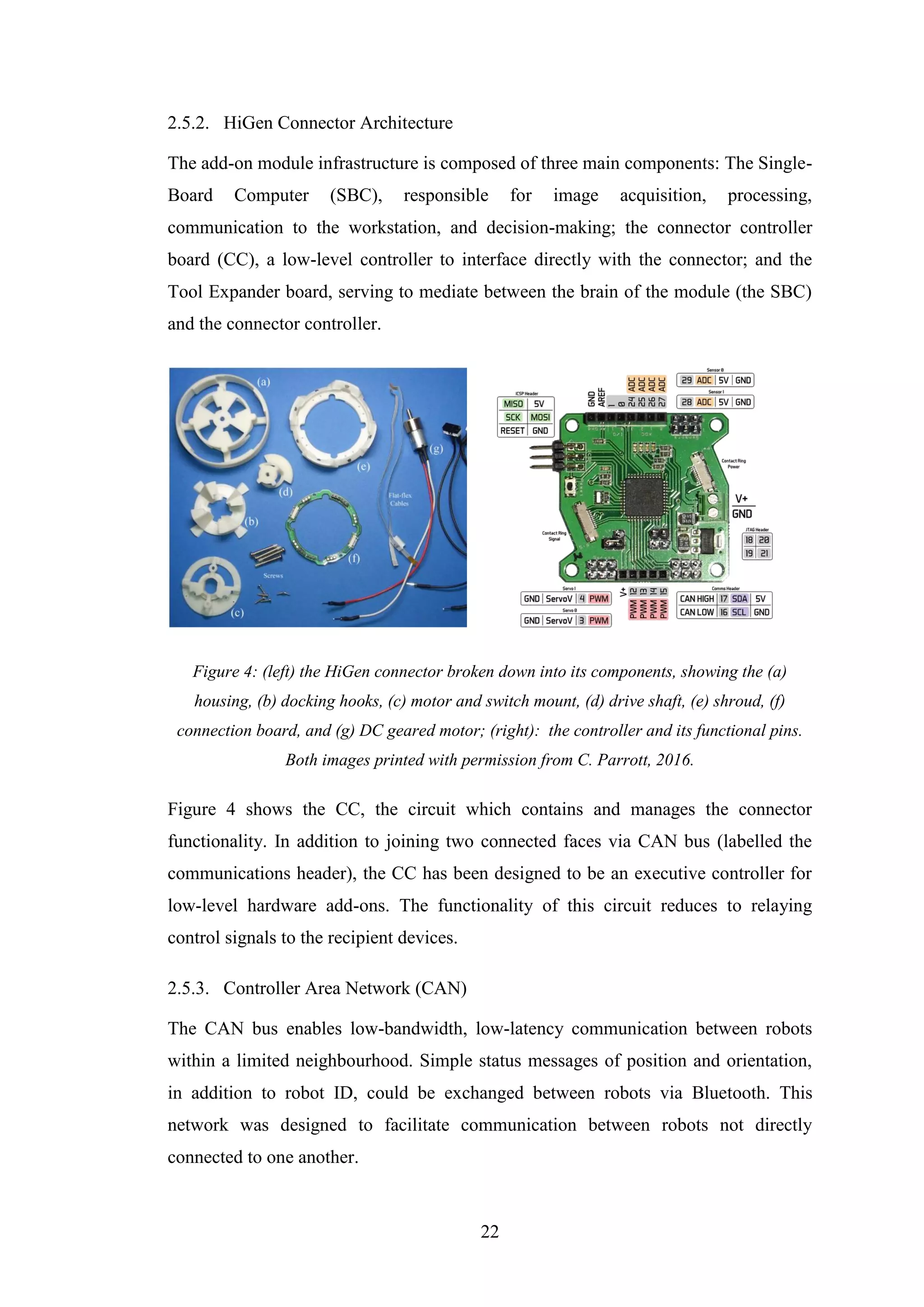
Figure 4: (left) the HiGen connector broken down into its components, showing the
(a) housing, (b) docking hooks, (c) motor and switch mount, (d) drive shaft, (e)
shroud, (f) connection board, and (g) DC geared motor; (right): the controller and its
functional pins. Both images printed with permission from C. Parrott, 2016. ............22
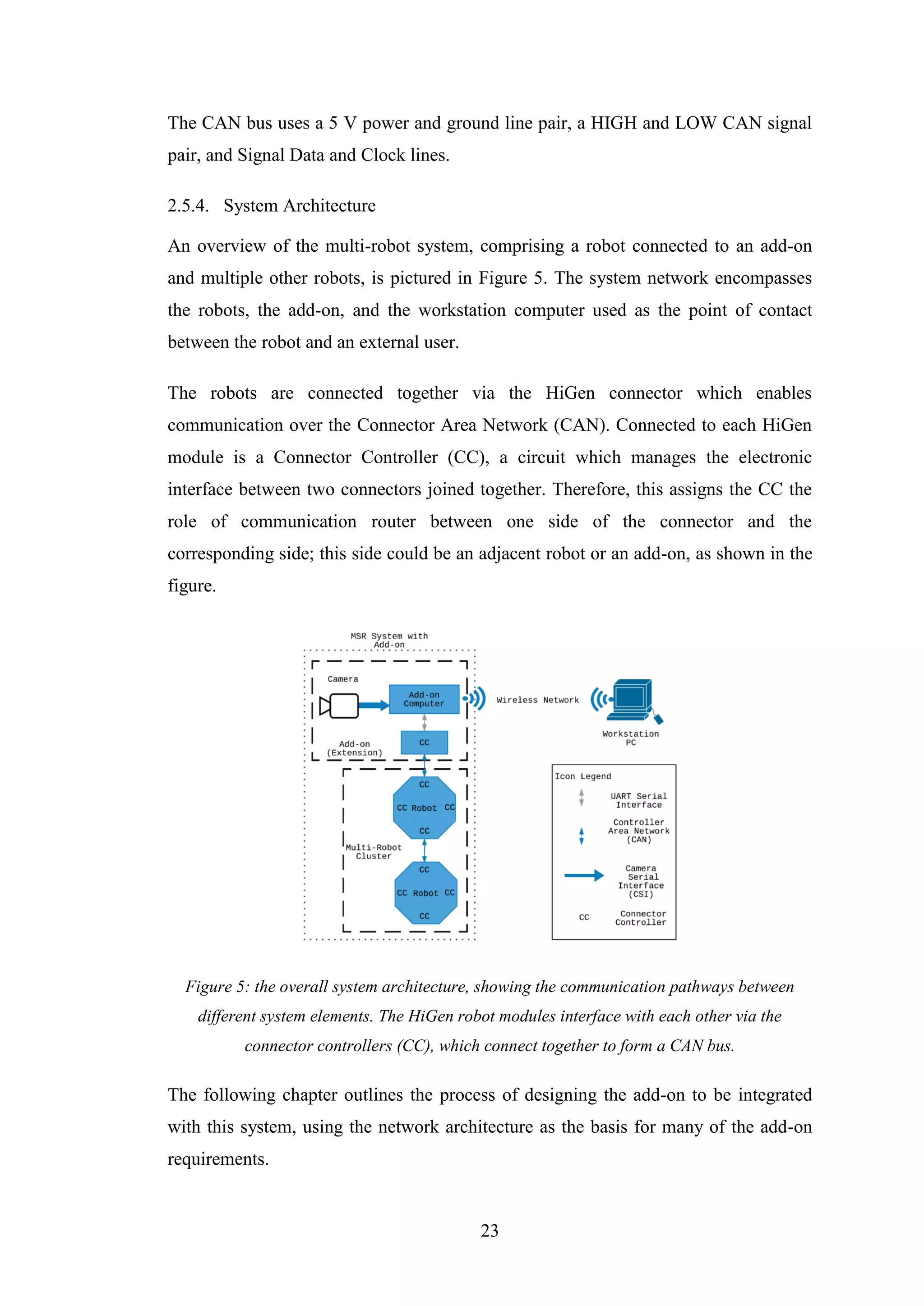
Figure 5: the overall system architecture, showing the communication pathways
between different system elements. The HiGen robot modules interface with each
other via the connector controllers (CC), which connect together to form a CAN bus.
......................................................................................................................................23
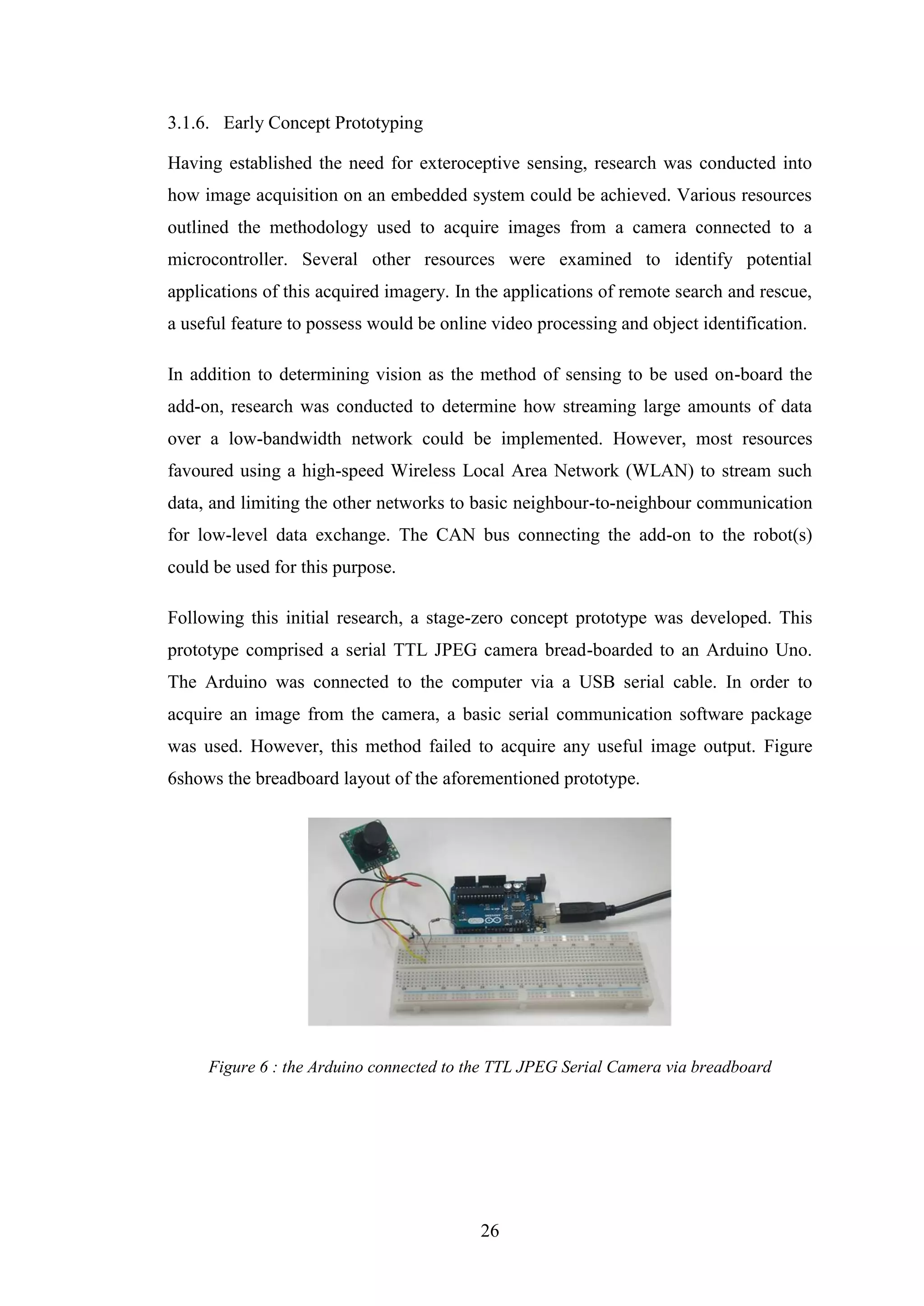
Figure 6 : the Arduino connected to the TTL JPEG Serial Camera via breadboard ...26
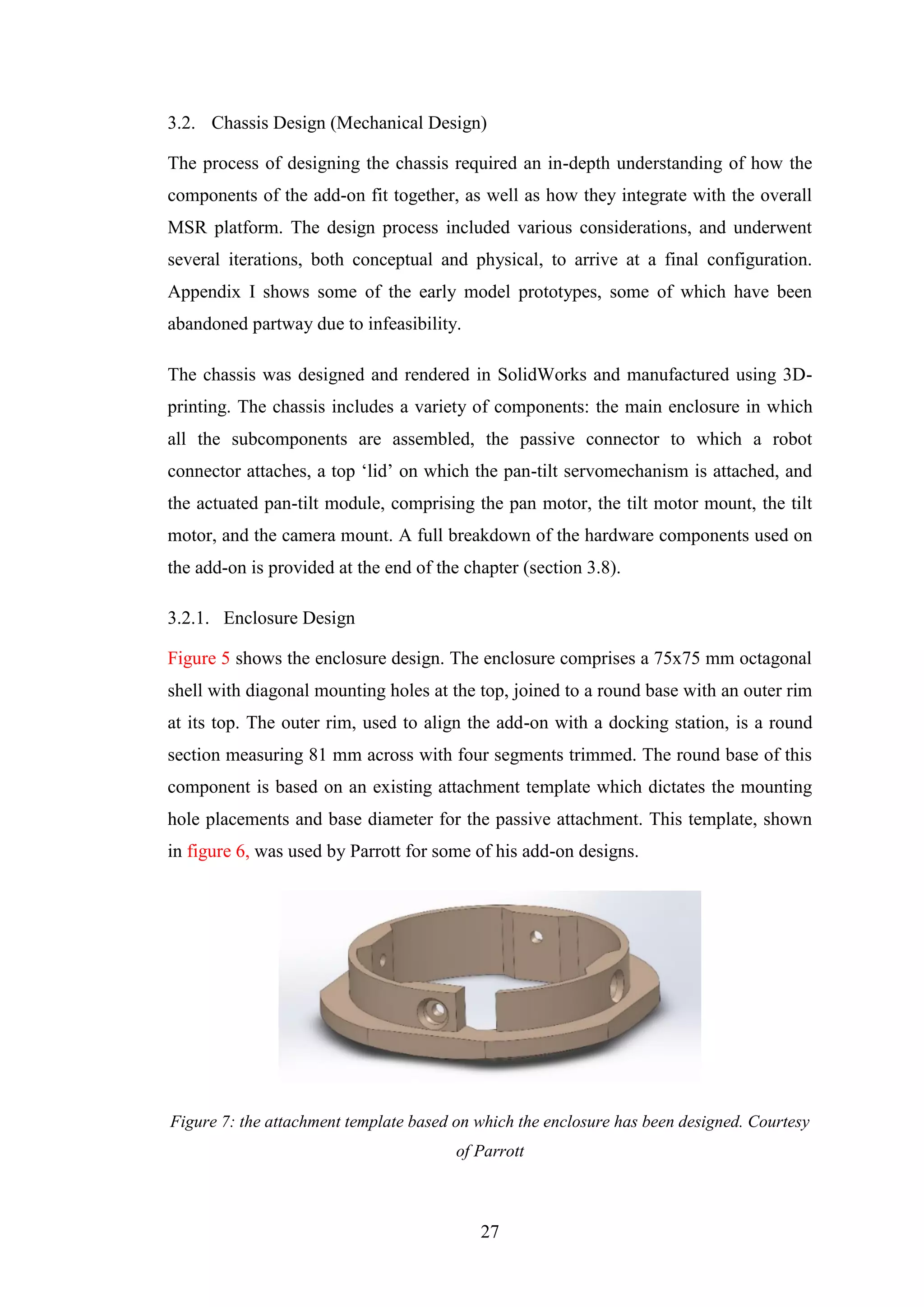
Figure 7: the attachment template based on which the enclosure has been designed.
Courtesy of Parrott.......................................................................................................27
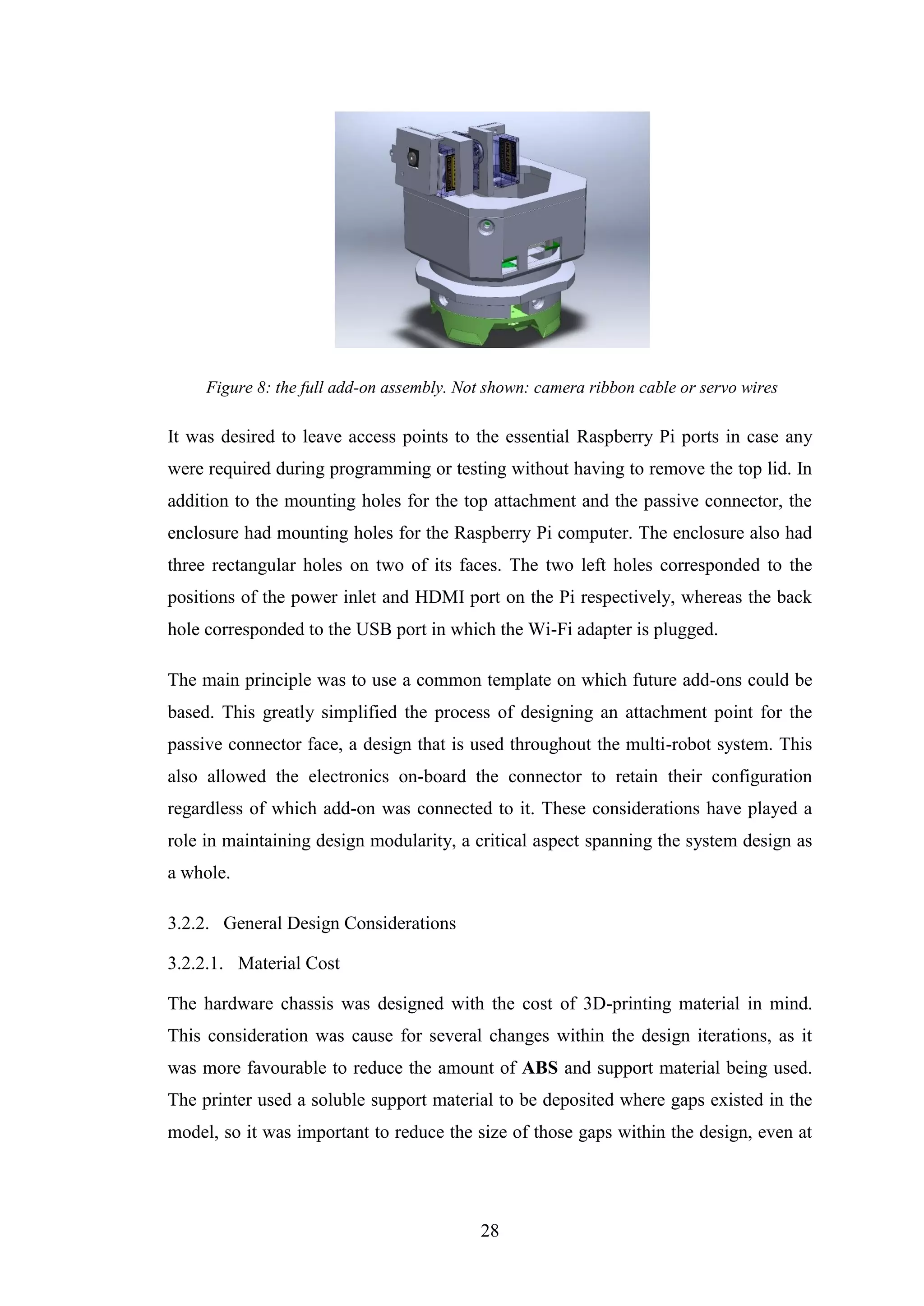
Figure 8: the full add-on assembly. Not shown: camera ribbon cable or servo wires.28
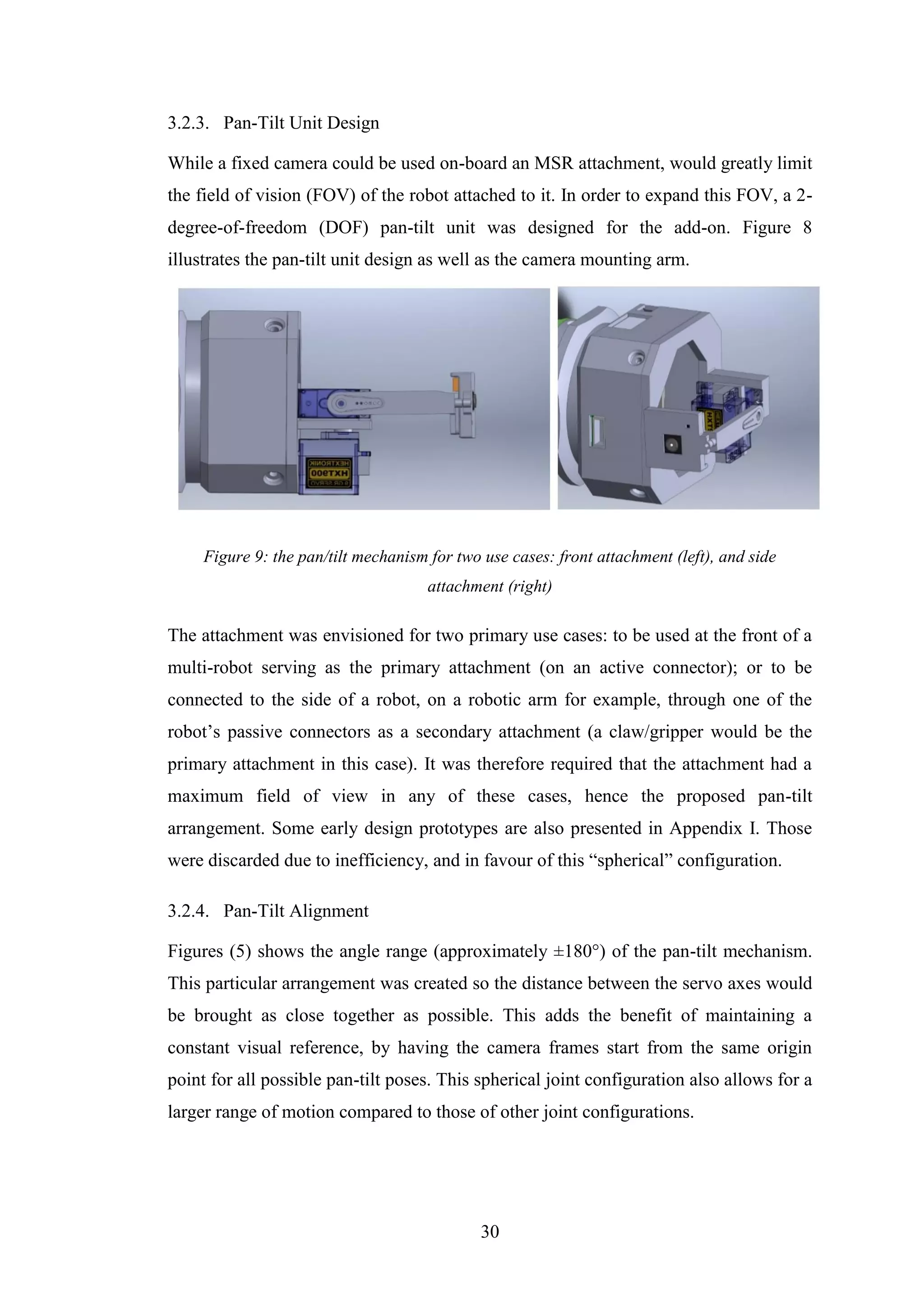
Figure 9: the pan/tilt mechanism for two use cases: front attachment (left), and side
attachment (right).........................................................................................................30
Figure 10: pan/tilt motion arcs, showing a range of approximately ±180° .................31](https://image.slidesharecdn.com/ca626474-80ef-4230-a9c1-9d2dbef4c309-160828124550/75/Mohamed-Marei-120126864-Dissertation-Design-and-Construction-of-Hardware-Add-ons-for-a-Modular-Self-Reconfigurable-Robot-System-10-2048.jpg)
![XI
Figure 11: four different single-board computers; Raspberry Pi 2 (left, back); ODroid
C1 (right, back); HummingBoard (left, front); MIPS Creator Ci20 (right, front).
Reproduced from [30]..................................................................................................31
Figure 12: (left) Raspberry Pi NoIR Camera. Retrieved from [31]; (centre) Teensy 3.2
LC (Low Cost). Retrieved from [32]; (right): Raspberry Pi Model A+. Retrieved from
[33]...............................................................................................................................33
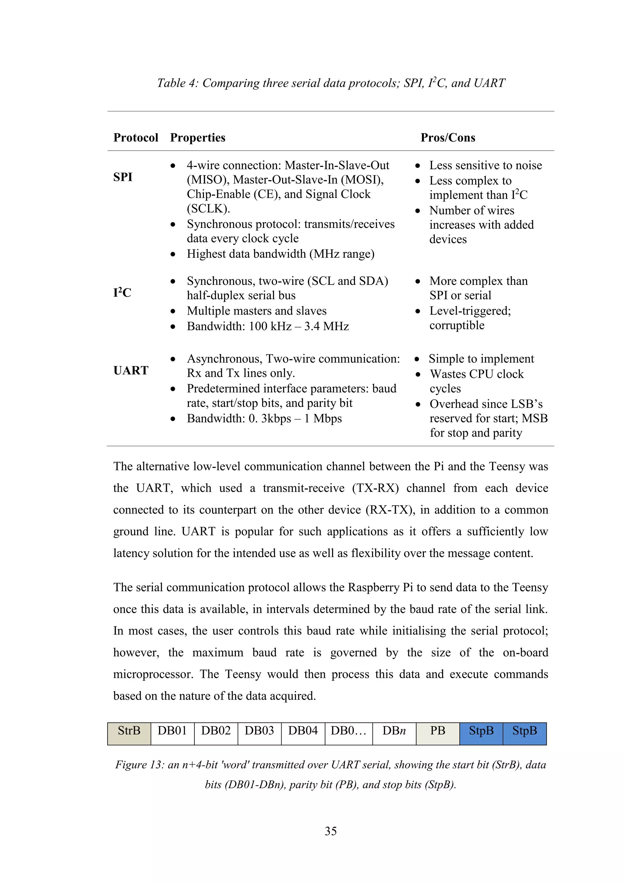
Figure 13: an n+4-bit 'word' transmitted over UART serial, showing the start bit
(StrB), data bits (DB01-DBn), parity bit (PB), and stop bits (StpB)...........................35
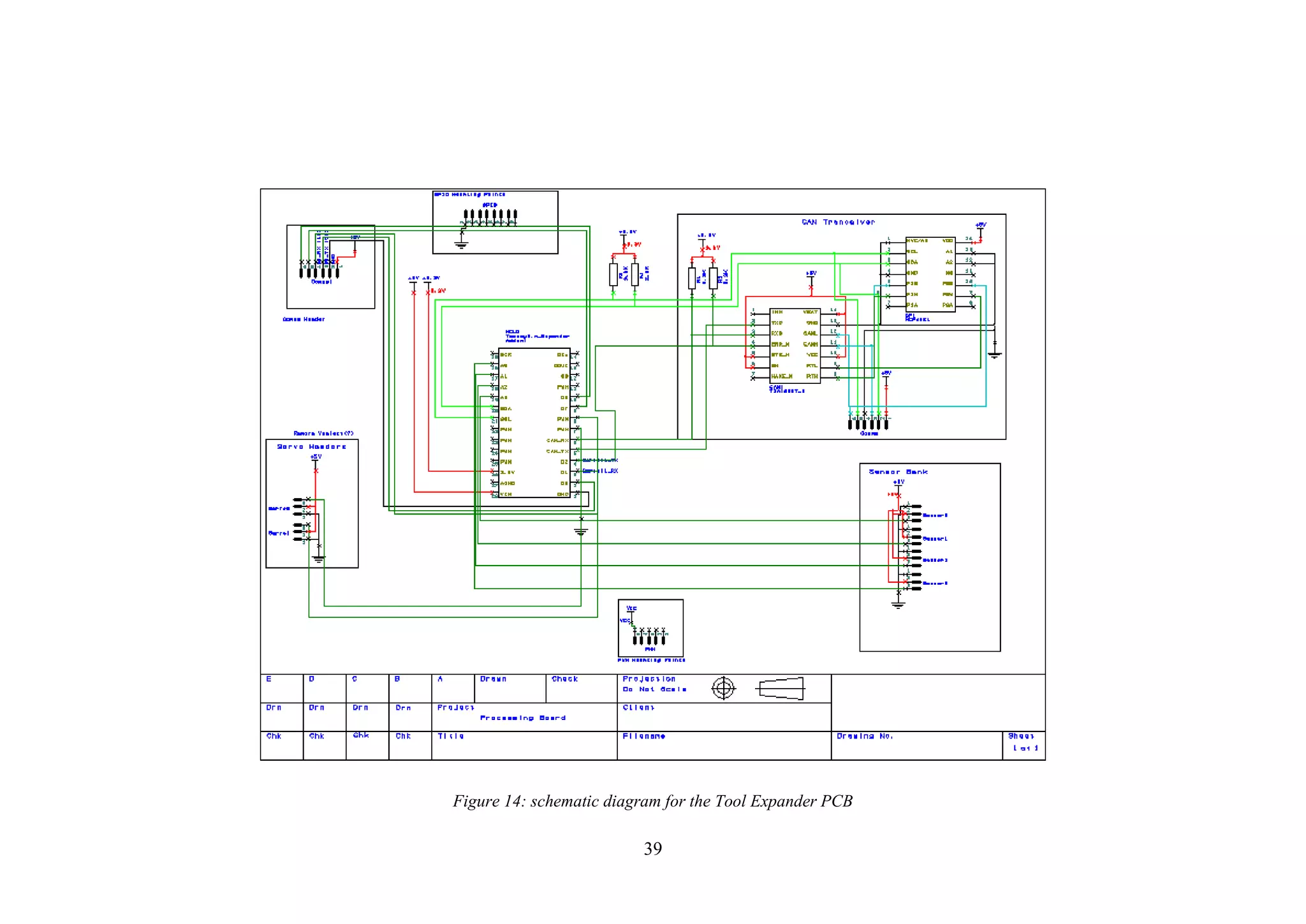
Figure 14: schematic diagram for the Tool Expander PCB.........................................39
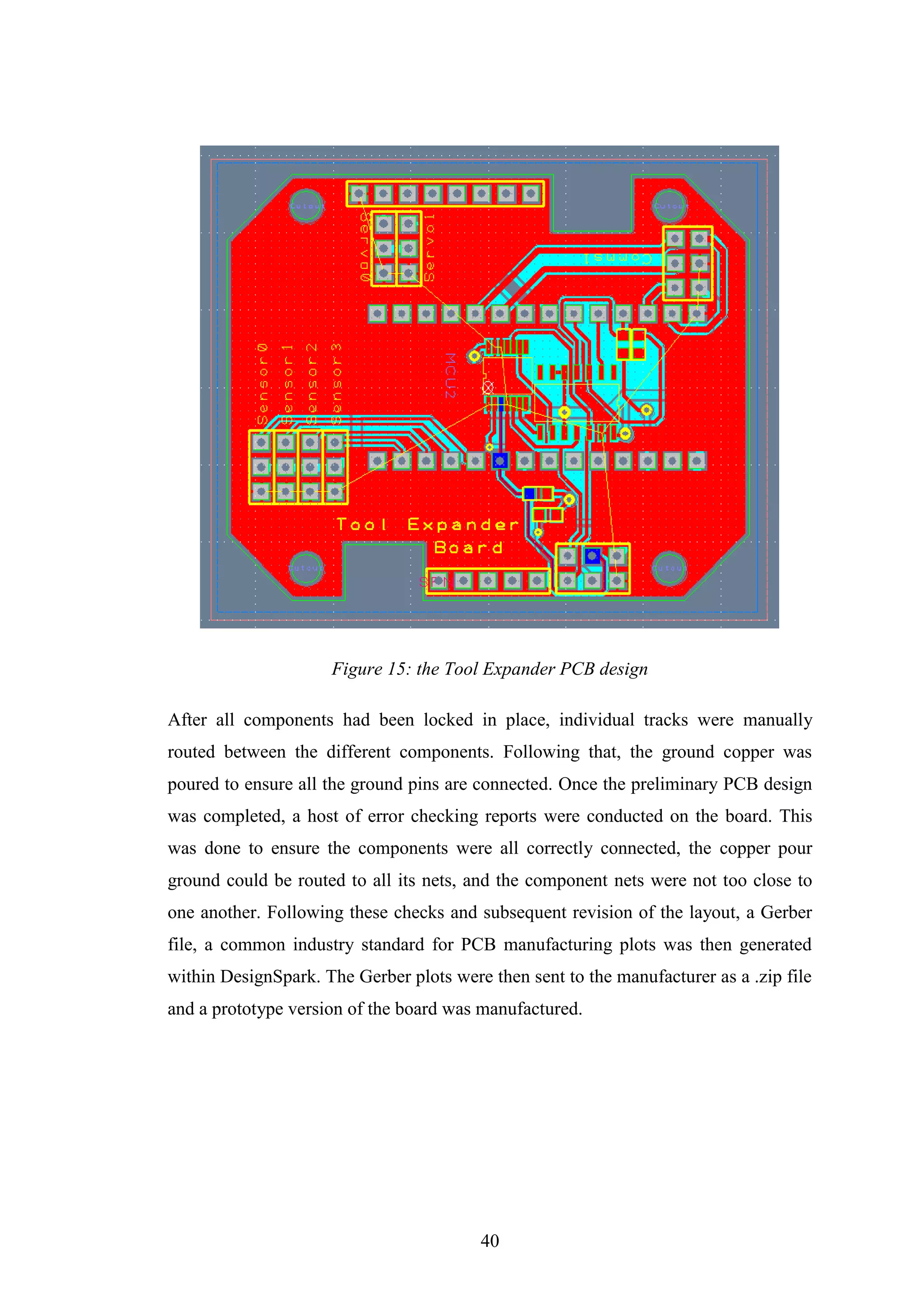
Figure 15: the Tool Expander PCB design..................................................................40
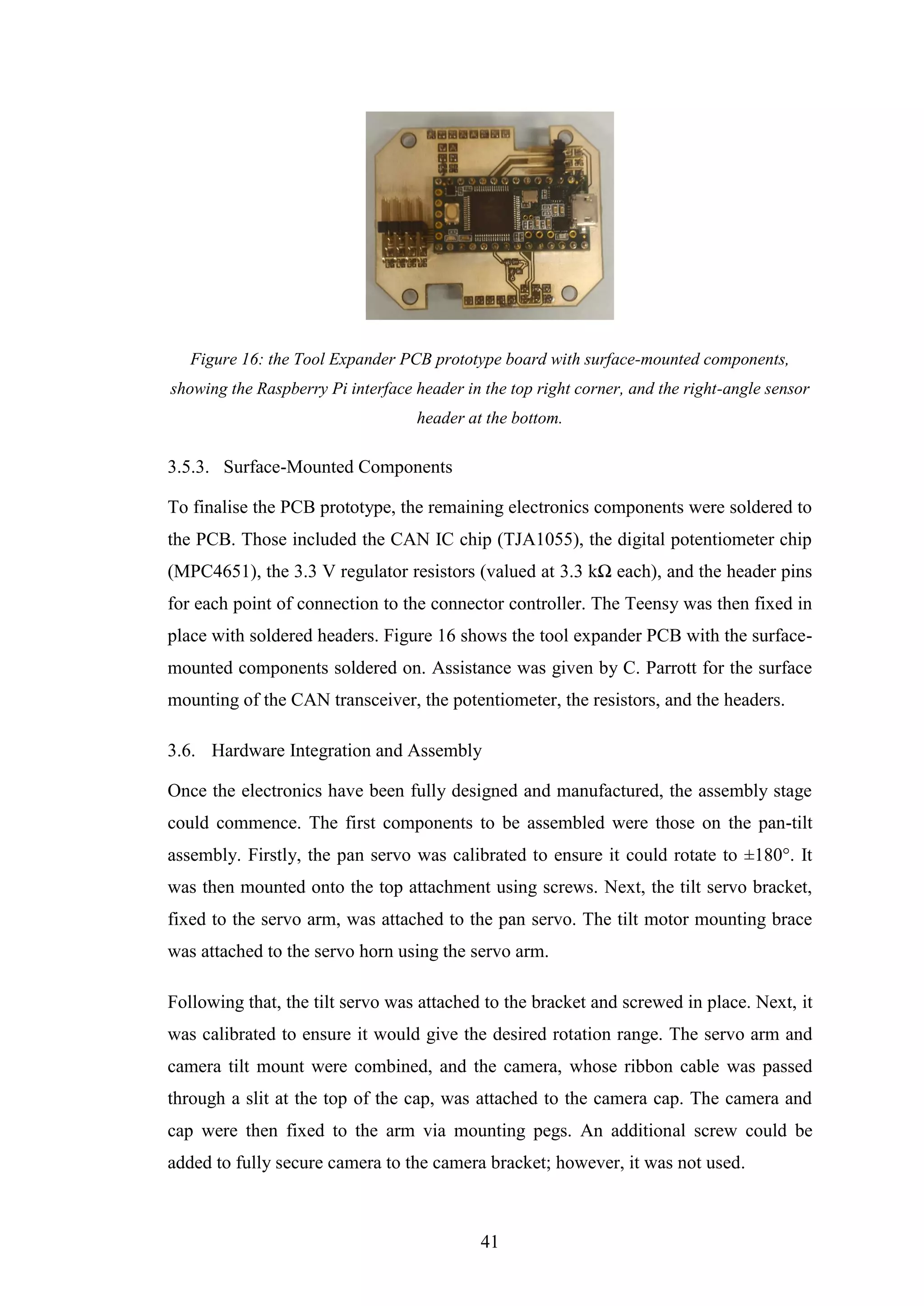
Figure 16: the Tool Expander PCB prototype board with surface-mounted
components, showing the Raspberry Pi interface header in the top right corner, and
the right-angle sensor header at the bottom. ................................................................41
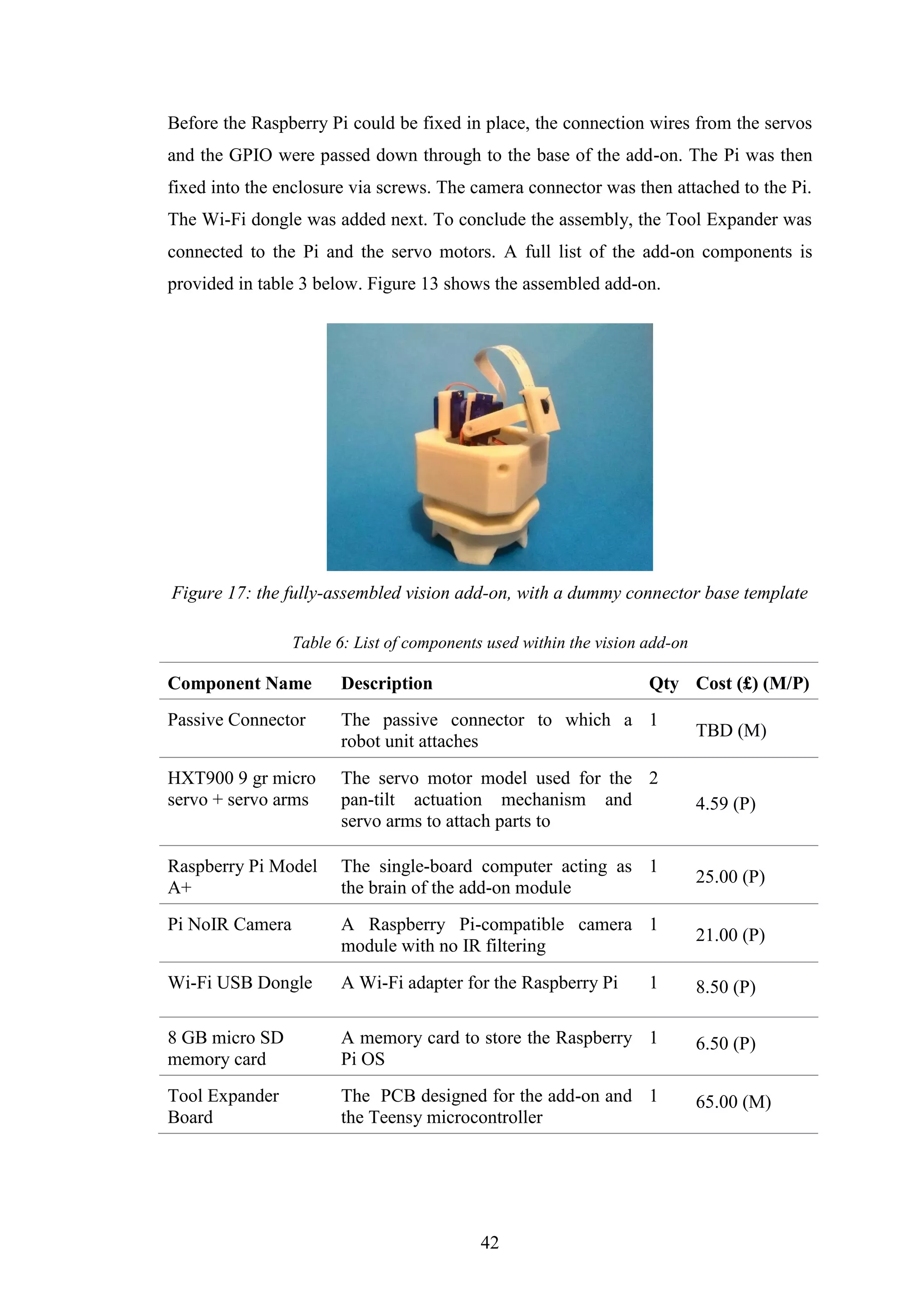
Figure 17: the fully-assembled vision add-on, with a dummy connector base template
......................................................................................................................................42
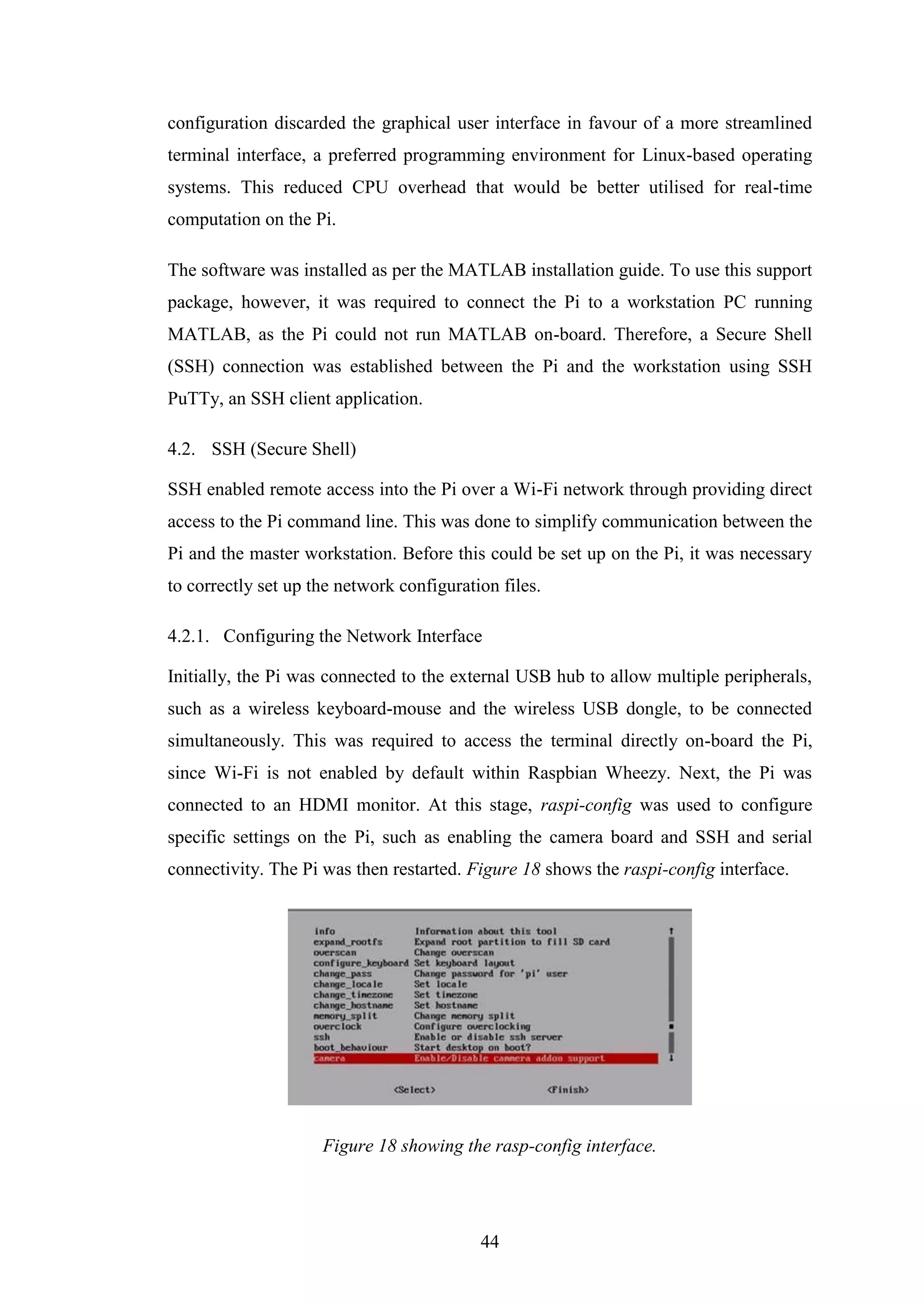
Figure 18 showing the rasp-config interface...............................................................44
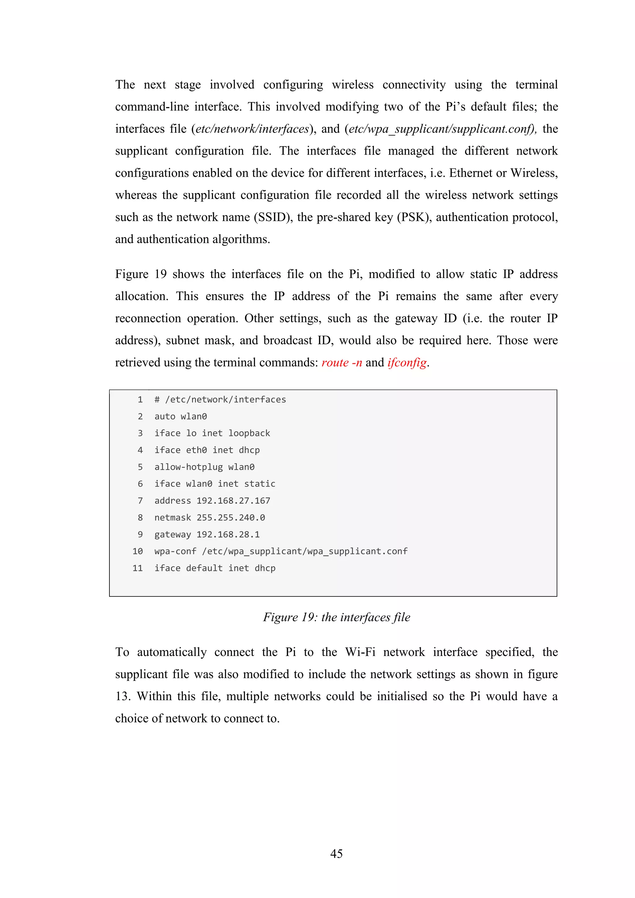
Figure 19: the interfaces file........................................................................................45
Figure 20: the supplicant configuration file................................................................46
Figure 21 showing the basic initialisation function for a Raspberry Pi board...........46
Figure 22 showing the cameraboard initialisation command using the board name
and resolution arguments (top) and the command line output (bottom) .....................47
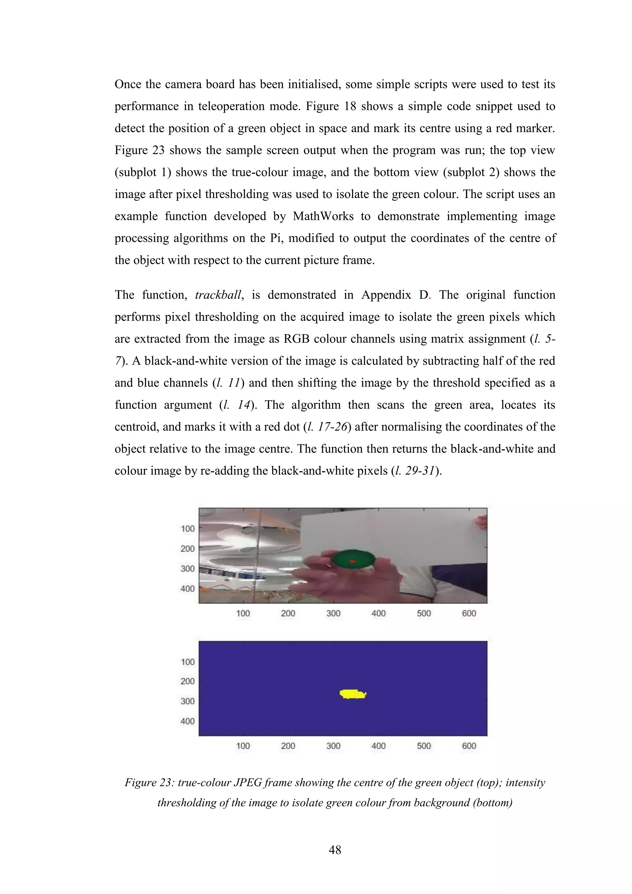
Figure 23: true-colour JPEG frame showing the centre of the green object (top);
intensity thresholding of the image to isolate green colour from background (bottom)
......................................................................................................................................48](https://image.slidesharecdn.com/ca626474-80ef-4230-a9c1-9d2dbef4c309-160828124550/75/Mohamed-Marei-120126864-Dissertation-Design-and-Construction-of-Hardware-Add-ons-for-a-Modular-Self-Reconfigurable-Robot-System-11-2048.jpg)
![XII
Figure 24: sample code that uses the trackball algorithm to track the position of the
green object..................................................................................................................49
Figure 25: serial device initialisation command; input arguments: host device name
(Raspberry Pi), serial port address, and baud rate .......................................................49
Figure 26: MiniCom used to input values to the serial port via SSH (left) and the
Arduino serial monitor echoing the data read (right)...................................................50
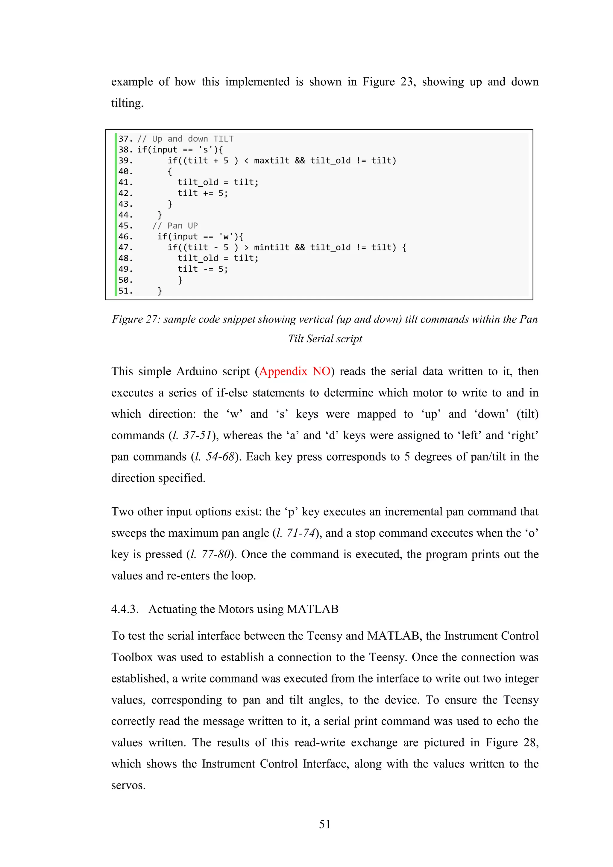
Figure 27: sample code snippet showing vertical (up and down) tilt commands within
the Pan Tilt Serial script...............................................................................................51
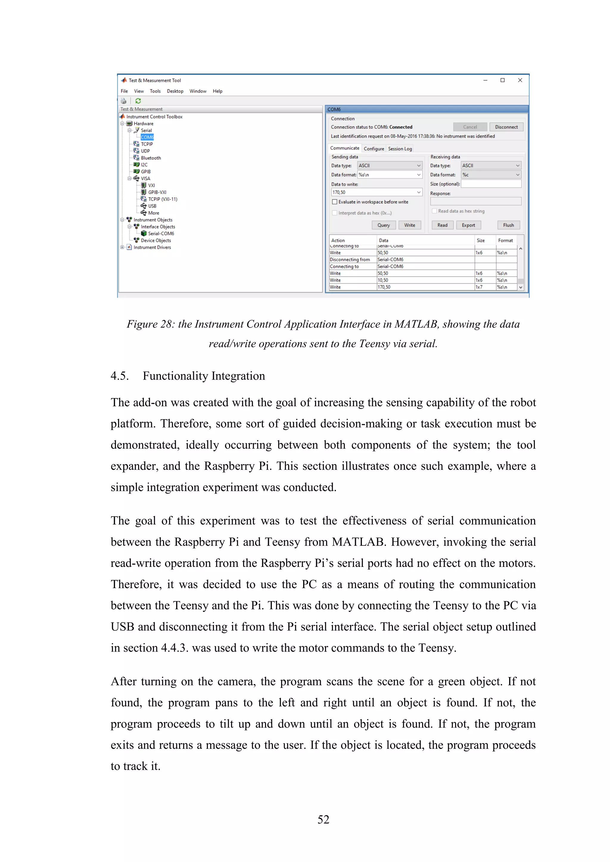
Figure 28: the Instrument Control Application Interface in MATLAB, showing the
data read/write operations sent to the Teensy via serial. .............................................52
Figure 29: (left) object centre and bounding box surrounding object; (right)
thresholded version of the image .................................................................................53
Figure 30: the point T (left diagram) corresponds to an equivalent point on an image
plane EFGH (the top of a frustum). The equivalent real-world plane in which T lies
maps out the base of a frustum, E’F’G’H (right). The frustum EFGH-E’F’G’H defines
the projection volume. Reprinted from [38]. ...............................................................55
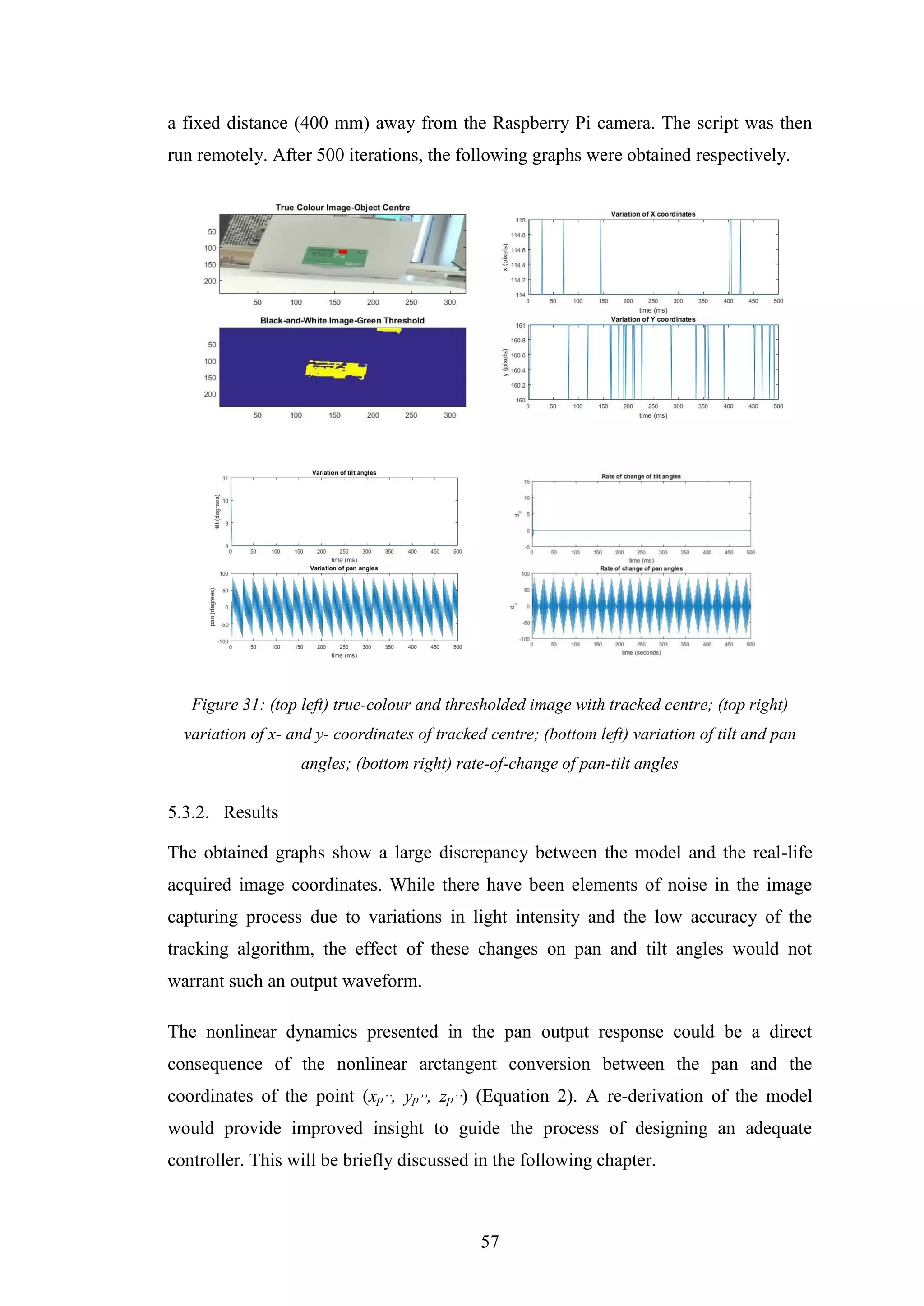
Figure 31: (top left) true-colour and thresholded image with tracked centre; (top right)
variation of x- and y- coordinates of tracked centre; (bottom left) variation of tilt and
pan angles; (bottom right) rate-of-change of pan-tilt angles .......................................57
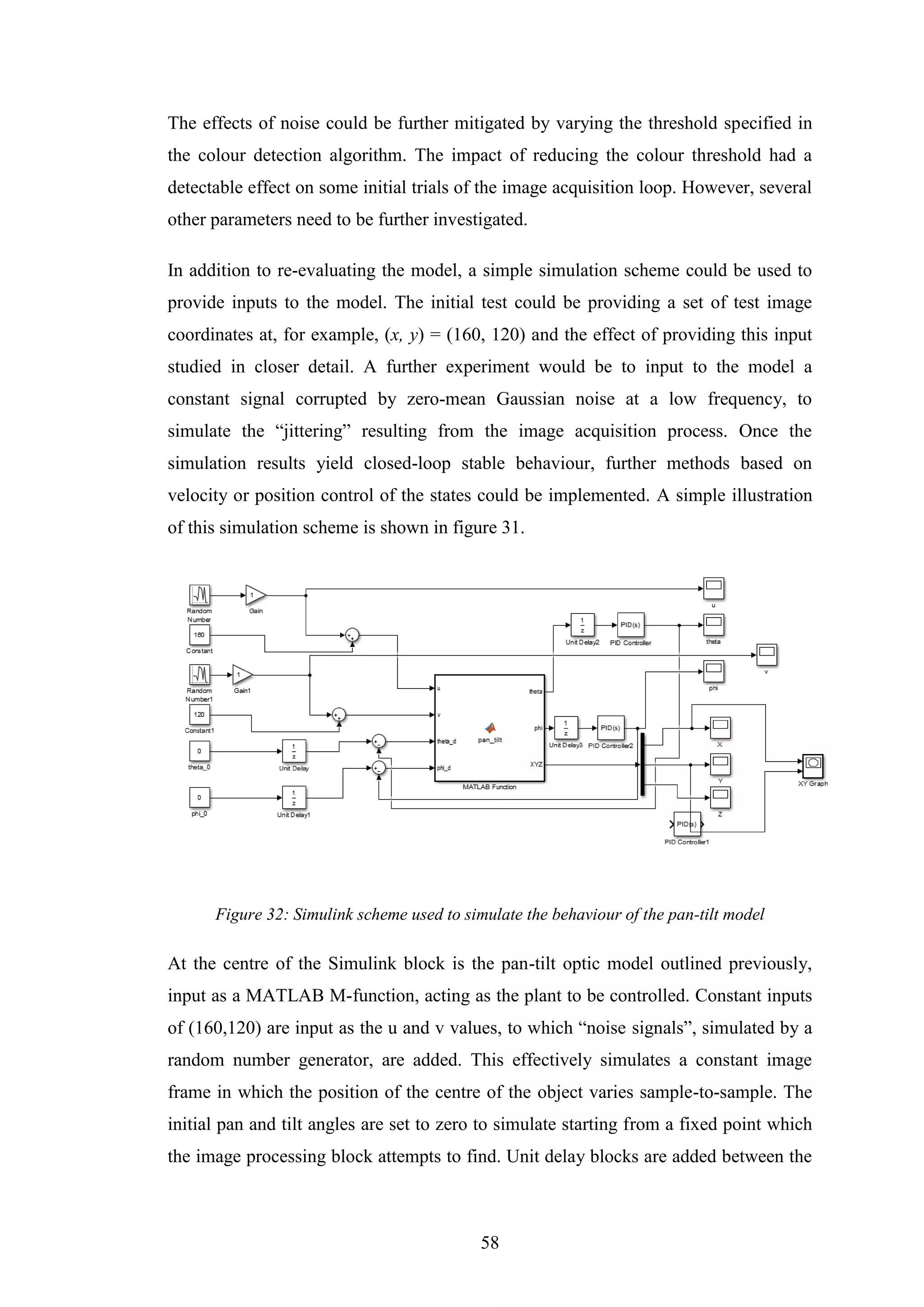
Figure 32: Simulink scheme used to simulate the behaviour of the pan-tilt model.....58
Figure 33: the camera calibration parameters..............................................................61
Figure 34: The camera calibration session in MATLAB. The checkerboard is used to
train the calibrator (top), which generates a pattern-centric view that shows the
position of the camera in the different frames (bottom). .............................................62](https://image.slidesharecdn.com/ca626474-80ef-4230-a9c1-9d2dbef4c309-160828124550/75/Mohamed-Marei-120126864-Dissertation-Design-and-Construction-of-Hardware-Add-ons-for-a-Modular-Self-Reconfigurable-Robot-System-12-2048.jpg)
![XIII
LIST OF TABLES
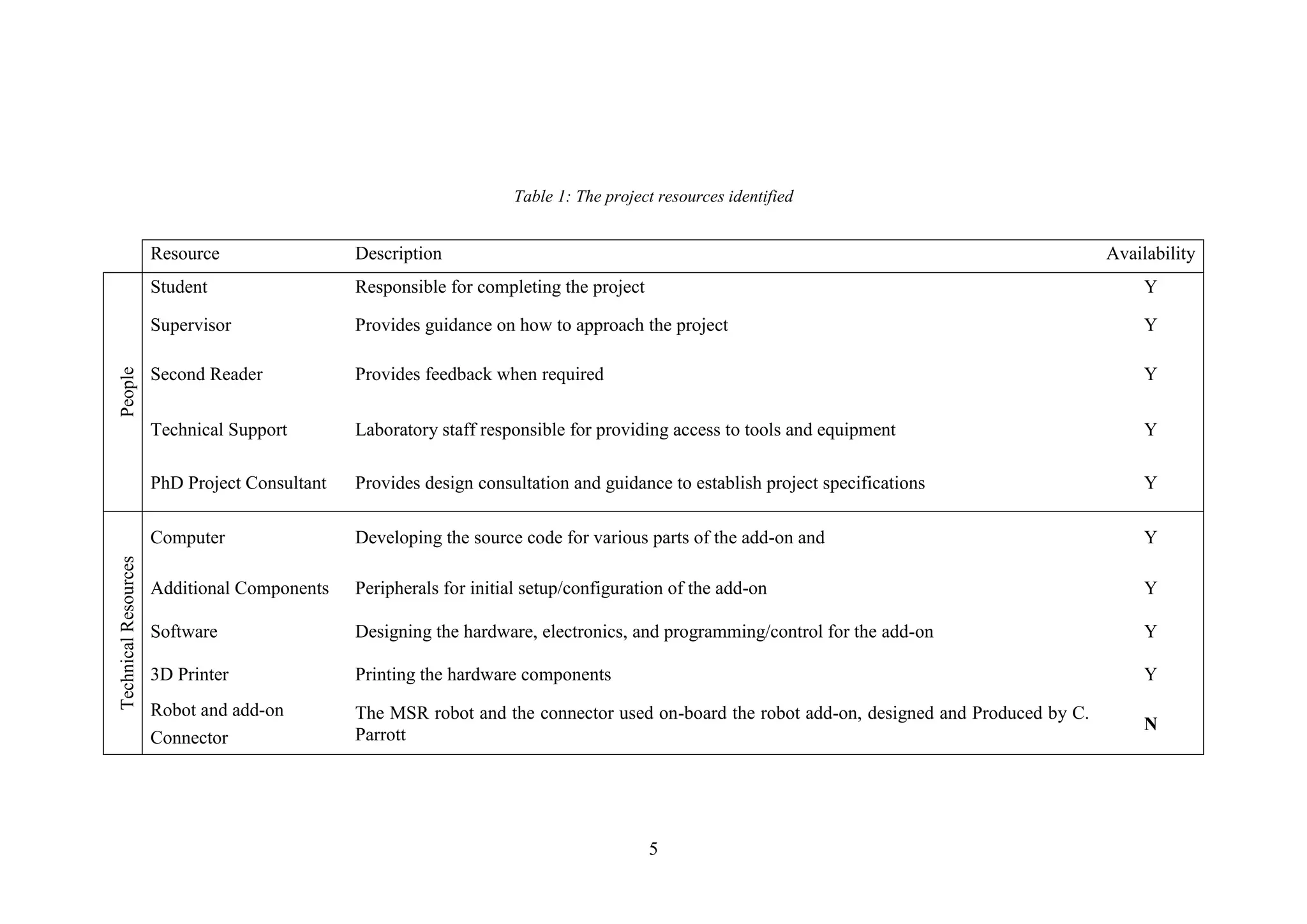
Table 1: The project resources identified ..................................................................................5
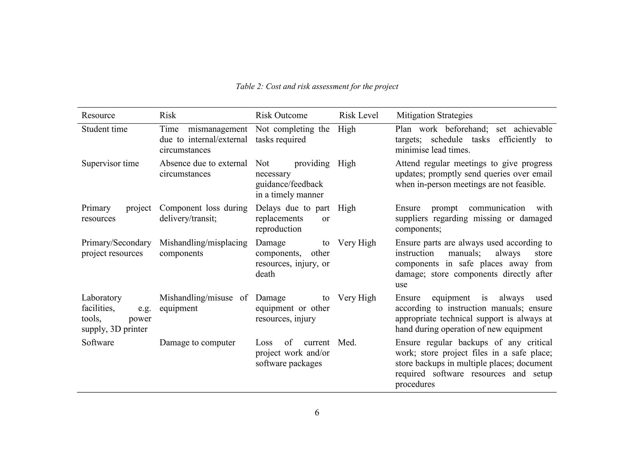
Table 2: Cost and risk assessment for the project .....................................................................6
Table 3: ATRON module [3], SMORES [9], AND HiGen [16] connectors and their
properties. ATRON image printed from [1]; SMORES image printed from [17]; HiGen image
printed with permission from C. Parrott..................................................................................14
Table 4: Comparing three serial data protocols; SPI, I2
C, and UART ...................................35
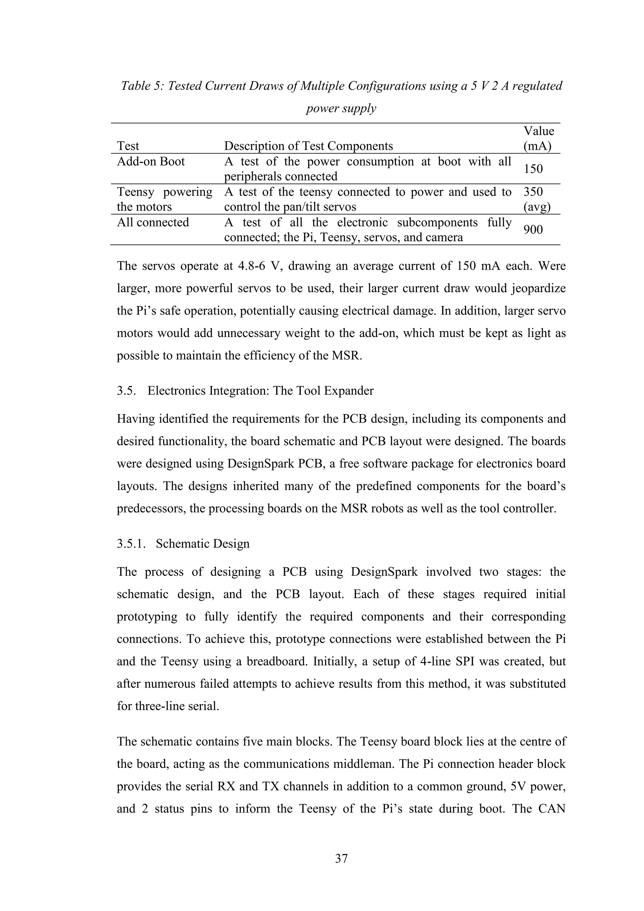
Table 5: Tested Current Draws of Multiple Configurations using a 5 V 2 A regulated power
supply.......................................................................................................................................37
Table 6: List of components used within the vision add-on ....................................................42
LIST OF EQUATIONS
Equation 1: the baud rate of the serial protocol for a word size of 12 and a 5 ms sample rate
.................................................................................................................................................36
Equation 2: the pan and tilt angles obtained from the inverse pipeline method described in
[34] ..........................................................................................................................................56
Equation 3: the visual servo (VS) problem as an error minimisation of the target feature w.r.t.
the current camera target. Reprinted from [32]......................................................................59
Equation 4: the interaction matrix of the point x. Reprinted from [32] ..................................59
Equation 5: image coordinates x and y defined in terms of the pixel coordinates (u and v), the
focal length (f), the camera centre (cu and cv), and the pixel ratio α. Reprinted from [32].....60
Equation 6: the velocity of x in terms of the linear and angular components of the target’s
motion ......................................................................................................................................60](https://image.slidesharecdn.com/ca626474-80ef-4230-a9c1-9d2dbef4c309-160828124550/75/Mohamed-Marei-120126864-Dissertation-Design-and-Construction-of-Hardware-Add-ons-for-a-Modular-Self-Reconfigurable-Robot-System-13-2048.jpg)
![1
Chapter 1 - Introduction
1.1. Background and Motivation
The concept of Modular Self-Reconfigurable Robots (MSR) has been an interest for
many different research groups and institutions. Research in this field has yielded
many unique implementations of multi-robot systems whose units can connect and
disconnect on demand, through actuated connector hubs, either autonomously or by
being joined and separated externally by an operator.
MSR platforms are commonly thought beneficial for modelling and simulating the
behaviours of self-assembling systems at different scales [1], including: enzyme-
substrate and hormone-drug interaction, programmable matter [2], insect swarm
systems [3], and several others. In addition, having a reconfigurable robot platform
could drive forward research in areas such as modular mobile robots [4] or
reconfigurable manufacturing systems (RMS) [5]. MSR systems have immense
potential in applications where cooperative robot behaviour is crucial, such as mobile
search-and-rescue, remote reconnaissance, and space exploration. Authors on this
subject recognize the potential of MSR and self-assembling robot systems, claiming
that once sufficient progress is made in their design as a whole, they will “cease to be
merely biologically inspired artefacts [sic] and become super biological robots” [6].
An MSR platform, however, is usually insufficient on its own - without some way of
showcasing, or indeed improving, its versatility. Often MSR systems are under-
equipped, with limited proprioceptive (internal) sensing and manipulation abilities;
the lack of exteroceptive sensors and manipulation tools limits their environmental
interaction and ultimately their effectiveness as robotic systems. Enter hardware
extensions (add-ons); they enhance the system capabilities by substituting their end-
effectors. For hardware extensions to work effectively with their intended platform,
they must comply with specific design criteria, dictated by the platform in question.](https://image.slidesharecdn.com/ca626474-80ef-4230-a9c1-9d2dbef4c309-160828124550/75/Mohamed-Marei-120126864-Dissertation-Design-and-Construction-of-Hardware-Add-ons-for-a-Modular-Self-Reconfigurable-Robot-System-16-2048.jpg)
![2
1.2. Problem Definition
The limited ability of MSR systems to perceive and affect their environment stands in
the way of practical realisations of such systems. Application-Oriented Hardware [1]
is therefore used to tackle this problem, by augmenting the robots’ sensory and/or
functional capabilities. To this end, a recent development at the University of
Sheffield, the HiGen Module [2], attempts to produce an MSR system which is
readily expandable through hardware add-ons. This project aims to further expand on
the applicability of hardware add-ons, through designing a complete multifunctional
add-on that could be readily integrated with the HiGen platform.
1.3. Aim of the Project
The aim of this project is to study, design, and build hardware extensions, or add-ons,
for an MSR platform currently under development at the University of Sheffield.
1.4. Objectives of the Project
The objectives of this project are:
1.4.1. Primary Objectives
Research the area of modular self-reconfiguring robots, and review the most
relevant implementations of MSR systems to date, including systems capable
of independent locomotion, heterogeneous systems, and systems with
hardware extensions (add-ons).
Research applications of MSR systems, including general and industrial
applications.
Design and program a hardware extension (add-on) to increase the sensing
ability of the MSR system under development.
Build, program, and test the hardware add-on.
1.4.2. Stretch Goals (Advanced Objectives)
Some advanced objectives have been outlined at the start of the project. However, due
to time constraints they were partially side-tracked to focus on the initial objectives.
Modify an existing hardware add-on to use in conjunction with the system.
Conduct experiments to ensure the efficacy of the hardware add-ons.](https://image.slidesharecdn.com/ca626474-80ef-4230-a9c1-9d2dbef4c309-160828124550/75/Mohamed-Marei-120126864-Dissertation-Design-and-Construction-of-Hardware-Add-ons-for-a-Modular-Self-Reconfigurable-Robot-System-17-2048.jpg)

![9
Chapter 2 - Literature Review
The concept of Modular Self-Reconfiguring Robots (MSR) has been an interest for
numerous different research groups and institutions. Research in this field has yielded
many unique implementations of multi-robot systems whose units can connect and
disconnect on demand, through actuated connector hubs, either autonomously or by
being joined and separated externally by an operator. However, an equivalent amount
of research has emerged attempting to assess the potential of MSR platforms in terms
of real-world applications.
This chapter highlights research endeavours in modular self-reconfiguring robot
systems, from their initial conception and a brief general history, to early
developments including a host of systems that have been designed for different
problems and use cases. It also introduces MSR systems with hardware add-ons and
Reconfigurable Manufacturing Systems (RMS). Next, the chapter illustrates some of
the implications of MSR system design as well as the challenges facing such systems.
Finally, the chapter introduces the HiGen connector and MSR system, for which the
hardware add-ons have been designed.
2.1. Modular Self-Reconfigurable Robots: A Brief Overview
In the 1940’s Alan Turing introduced the concept of a universal computation device
[1], one that could perform any task required through reprogramming. By the 1970’s
personal computers had gained significant traction within the consumer goods market,
ushering in a new age of innovation through technology, consequently fulfilling
Turing’s vision. Successive advancements in computer technology have driven
numerous innovations in mobile robotics, and in turn, small-scale mobile robots.
1988 marked the first theoretical implementation of a dynamically reconfigurable
modular robot, one that could be constructed from basic ‘cells’ or ‘modules’ and
reconfigured autonomously as per the desired use case [3]. Following on from these
theories, many research groups have successfully built and simulated robotic systems
comprising basic modules capable of different types of reconfiguration.](https://image.slidesharecdn.com/ca626474-80ef-4230-a9c1-9d2dbef4c309-160828124550/75/Mohamed-Marei-120126864-Dissertation-Design-and-Construction-of-Hardware-Add-ons-for-a-Modular-Self-Reconfigurable-Robot-System-24-2048.jpg)
![10
As of 2014 there have been at least 40 different implementations -and counting- of
MSR systems, with each system aiming to address a specific set of design challenges.
These challenges encompass novel connector designs, unique control methodologies,
or improved communication, to name a few. It is worth noting that some of these are
iterations of previous systems.
2.2. Modular Self-Reconfigurable Robot Systems: Taxonomy and Attributes
MSR platforms comprise basic building blocks that can reconfigure into different
shapes to perform the desired task. A single module contains all the working internals
of a robot: sensing, actuation, battery, and processing power. Though virtually useless
as individual robots, MSR platforms draw their immense potential from scalability;
ten, even hundreds, of modules can combine together in any configuration forming
rigid, complex structures and functional limbs. An example of a MSR platform, the
ATRON self-reconfigurable robot [4], is shown in Figure 1, with individual modules
combined into different configurations.
MSR systems are classified into three main archetypes: pack robots (consisting of
dozens of robots within the same system); herd robots (with several hundred modules
per system); and swarm robots, whose numbers are typically many thousands of units.
The significance of each module within the system decreases proportionally with the
size of the MSR population; pack robots are the most dependent on the actions of
each individual, whereas in large swarms of robots no particular attention is paid to
single modules, much like natural swarm systems.
Another method of classifying MSR platforms is based on their reconfiguration
abilities. The robots are said to be reconfigurable if they can be
connected/disconnected and combined into different configurations; dynamically
reconfigurable, if they can disconnect /connect while modules are active (hot-
swapping); and self-reconfigurable, if they can be connected/disconnected
autonomously, without external aid.
This section introduces the general attributes of MSR systems, including their
morphology, locomotion classes, control, connector design, and communication
methods, with references to existing implementations.](https://image.slidesharecdn.com/ca626474-80ef-4230-a9c1-9d2dbef4c309-160828124550/75/Mohamed-Marei-120126864-Dissertation-Design-and-Construction-of-Hardware-Add-ons-for-a-Modular-Self-Reconfigurable-Robot-System-25-2048.jpg)
![11
Figure 1: the ATRON self-reconfigurable robot combined into a snake configuration (left), a
vehicle-like configuration (right), and an intermediate configuration (back). Printed from [3]
2.2.1. Morphology: Lattice, Chain, and Hybrid
MSR systems are commonly characterized using their morphology [1], which is
primarily concerned with how the robots are assembled into structures. Chain-systems
are where the individual robots combine together end to end in chain-like shapes,
trees, and loops in some cases. Lattice-systems, such as Fracta [5] and the
Metamorphic Robot [6], are examples of predominantly planar (2D) architectures
where each robot unit is connected to two or more units, consequently requiring
multiple connection points. Robots in a lattice only connect in discrete points in the
configuration, akin to how atoms combine to form structural lattices. Hybrid
architectures, such as the ATRON [4], also exist where combinations of chain clusters
and lattice structures could be formed using the same basic building blocks [7]. Such
systems allow multiple legs to assemble, providing greater locomotion versatility,
whereas lattice arrangements allow rigid support structures to form, improving the
stability of the whole system, in addition to facilitating self-reconfiguration tasks. For
these reasons, hybrid architectures tend to prevail throughout MSR designs.
Determining the intended morphology of the system is a consideration that takes form
at the module and system level alike. As shown in figure 2, Stoy et al. have
demonstrated that the MSR morphology largely dictates other aspects of the design
[4]. The fact that most morphologies tend to be hybrid slightly simplifies this from a
mechatronic design point of view, but might cause a plethora of challenges for control
design. This will be discussed later in this section.](https://image.slidesharecdn.com/ca626474-80ef-4230-a9c1-9d2dbef4c309-160828124550/75/Mohamed-Marei-120126864-Dissertation-Design-and-Construction-of-Hardware-Add-ons-for-a-Modular-Self-Reconfigurable-Robot-System-26-2048.jpg)
![12
Figure 2 showing the components involved in robot design and their interaction. Adapted
from [8]
2.2.2. Locomotion Modes
A crucial design element for MSR platforms, and perhaps one of their most
advantageous traits, is the various locomotion modes they inherently support through
reconfiguration [3] [8]. Some MSR systems have been created to have independently
mobile modules, such as M3
Express [9], SMORES [10], M-TRAN [11] and PolyBot
[12] [13], whereas most are only capable of propulsion in clusters [4]. Many MSR
systems can form into different configurations capable of varying locomotion modes.
For example, ATRON [4] can form snake-like or “wheeled” robots, and M-TRAN
can form into multi-legged configurations. Kutzer et al. proposed a MSR design with
a hybrid morphology, whose modules were capable of self-propulsion on disc-shaped
connectors that doubled as wheels [9]. Those could be used to propel individual
modules or a large multi-robot cluster.
Another interesting prospect for MSR locomotion lies in the individual flexibility and
self-locomotion of the modules combined with the structural support and rigidity of
the MSR as a whole. Within a large cluster or multi-robot, robots could move from
the back of the configuration to the front, or holes move to the back of the robot,
creating what is known as cluster flow [14], moving the robot in a specific direction.
Several examples of cluster flow exist in MSR platforms, both physical and
simulated, some of which have been reviewed in [15]. Similar behaviour is exhibited
in real-life insect swarm systems such as ant colonies, whereby ants form into large
structures that self-propel across a terrain or conform around an obstacle to navigate
their path.](https://image.slidesharecdn.com/ca626474-80ef-4230-a9c1-9d2dbef4c309-160828124550/75/Mohamed-Marei-120126864-Dissertation-Design-and-Construction-of-Hardware-Add-ons-for-a-Modular-Self-Reconfigurable-Robot-System-27-2048.jpg)
![13
The locomotion versatility of MSR platforms proves invaluable in the presence of
unstructured environments, making them ideal candidates for space exploration,
reconnaissance, or remote search and rescue tasks. However, until certain design
challenges are mostly overcome, these benefits remain largely hypothetical, save for
the few example MSR systems that have demonstrated animal-like locomotion.
Cluster flow and task-based growth are examples of challenges that might be
overcome once single modules are efficient enough.
2.2.3. Control
Self-reconfiguration control in MSR systems poses a significant multi-layer
challenge. At the module level, control of on-board mechatronics to arrive at the
desired configurations requires a complete understanding of the system kinematics,
posing a hardware challenge of itself. The obvious solution to this problem is to
restrict the DOF count on each module, rendering them simpler but less versatile.
Even controlling chains of simple 2DOF modules becomes challenging from a
software perspective. Adding an extra module increases the difficulty of docking two
units at different points together, as arm, and therefore chain, poses grow less singular
and more error-prone with each joint added [1], unless direction constraints are
employed. This increase in complexity degrades the computational efficiency of the
controller in question. For embedded controllers, this becomes even more
challenging, as individual robots are, by design, often limited in terms of memory and
processing power.
Globally, it is not feasible to instruct all modules to converge to a certain
configuration; however, it is possible to guide them to incrementally approach one
another, thereby allowing them to reconfigure [1]. Some researchers proposed control
paradigms by which only certain modules performed the required control action; the
surrounding modules then use their internal models to “follow suit”, effectively
enabling the modules to form the desired configuration or execute cluster flow. This
leader-follower approach has been adopted by Stoy and Nagpal [16].
Control of individual modules is almost only necessary in cases where precise self-
reconfiguration is required, for example if the end-goal is to reconfigure into a
specific shape, such as an arm or leg for locomotion. However, for some tasks such as](https://image.slidesharecdn.com/ca626474-80ef-4230-a9c1-9d2dbef4c309-160828124550/75/Mohamed-Marei-120126864-Dissertation-Design-and-Construction-of-Hardware-Add-ons-for-a-Modular-Self-Reconfigurable-Robot-System-28-2048.jpg)
![14
cluster flow locomotion and task-driven growth, it might not be entirely necessary, or
indeed feasible, to control individual robot modules.
2.2.4. Connector Design
A fundamental hardware challenge for MSR platforms lies in the design of robust
connectors capable of lifting multiple units in series, with minimal actuation time. Of
great importance, as well, are the modules’ having a simple alignment mechanism and
control implementation. Genderless connectors excel in comparison to the other
methods. Connectors can be mechanical, electromagnetic, or magneto-mechanical,
though other methods have also been used.
In [2] Parrott et al. compared three classes of connector designs: gendered, where
male connectors latch onto chassis parts by means of hooks or pins; bi-gendered
(hermaphrodite), where pins/hooks latch into connector grooves; and genderless,
where two hooks latch together. Table 1 presents some different connectors that have
been implemented, comparing their properties.
Table 3: ATRON module [4], SMORES [10], AND HiGen [2] connectors and their
properties. ATRON image printed from [1]; SMORES image printed from [17]; HiGen image
printed with permission from C. Parrott.
Robot
System ATRON SMORES HiGen
Connection
Mechanism
Mechanical Magneto-Mechanical Mechanical
Connector
Gender
Gendered (male
hooks attach to
female slots)
Bi-gendered (modules
have in-built features
of both genders)
Genderless
(connecting faces
have identical
interlocking hooks)
Connector
Face
(Pictured)](https://image.slidesharecdn.com/ca626474-80ef-4230-a9c1-9d2dbef4c309-160828124550/75/Mohamed-Marei-120126864-Dissertation-Design-and-Construction-of-Hardware-Add-ons-for-a-Modular-Self-Reconfigurable-Robot-System-29-2048.jpg)
![15
2.2.5. Sensing
Numerous experiments conducted on MSR platforms aim to understand how capable
the modules are of cooperating under various circumstances. The limited capabilities
of MSR platforms in the way of exteroceptive sensing consequently limits their task
execution abilities. Most MSR systems are restricted to using a few types of
exteroceptive sensors (that measure external environmental variables such as
temperature, humidity, light), save for SWARM-bot [18] which employed various
exteroceptive and proprioceptive sensors. Consequently, if the robots were to affect
their external environment, some way of enhancing their awareness of their
environment is crucial for cooperation, particularly in unstructured settings. Several
researchers have devised non-vision solutions to tackle the problem of self-
reconfiguration, one of the most challenging aspects of MSR implementation.
Payne et al. [19] propose localization based on elliptical approximations to estimate
probable robot locations. While their algorithm is fast and light, producing robust
estimates of robot locations from one Infrared sensor per robot in a few samples, it is
sensitive to varying light intensities and is therefore less effective in environments
with varying lighting. Furthermore, the availability of cheap low-power
microprocessor and memory modules renders computational requirements trivial, so
embedded robust sensing can easily be exploited.
2.2.5.1. Vision: Motivation
Vision presents itself as a suitable candidate due to its simple implementation and
relatively well-understood requirements. A multitude of different camera technologies
that can generate medium-resolution, high-speed video or MJPEG (a sequence of
JPEG images “stitched” together to form low-framerate video) do exist, rendering the
task more manageable. Simple implementations of camera-based navigation use low-
level image processing to guide the robots’ decision-making with respect to the
environment, or based on the task at hand.
2.2.5.2. Vision: Implementation
In experiments by Yim et al. [20] [21], the CKBot system used smart camera
attachments on three module clusters (each cluster comprised four modules connected
together) to form a bipedal robot. Each camera comprised a VGA imager, an Analog](https://image.slidesharecdn.com/ca626474-80ef-4230-a9c1-9d2dbef4c309-160828124550/75/Mohamed-Marei-120126864-Dissertation-Design-and-Construction-of-Hardware-Add-ons-for-a-Modular-Self-Reconfigurable-Robot-System-30-2048.jpg)
![16
Devices Digital Signal Processor, a 3-axis accelerometer, and a wide-angle signalling
LED. The camera communicated with the robots over a CAN bus, and the robots
could be fitted with Bluetooth transceivers for wireless cluster intercommunication.
The module also featured an independent power supply, increasing the duration of its
usability. It was screwed to the robot cluster, as opposed to using the magnetic
connectors on-board the modules. To test the effectiveness of this vision and
signalling platform, the robot was forcefully separated (or exploded) by a kick from
the experimenter. Using visual servoing, the clusters autonomously scanned the scene,
detected LED signals from the other robots and moved towards them. The clusters
successfully regrouped, realigned and reconnected into their previous configuration.
Vision has also been implemented within the CONRO system [22]. The researchers
have devised a simple CMOS camera sensor that could be attached to some of the
robot modules. The module was capable of capturing 8-bit monochrome images at 30
fps. While the modules did not have the computational capabilities to capture or
process the image at the time, it was a step forward in empowering simple MSR
robots with camera sensors.
Simple 2D-vision is not the end goal, however. Some experts suggest using multiple
MSR clusters to create 3D maps of their surroundings using inexpensive cameras and
IR transceivers, as opposed to expensive sonar or LiDAR (Light Detection and
Ranging) sensors. This would be practical in applications where creating a 3D map of
an inaccessible environment is required, such as in a collapsed building, inside a tank
or cave. Powerful and inexpensive computers would allow sophisticated image
processing software to be embedded, and enable the robot to do more with the data
collected.
2.2.6. Communication
Many MSR platforms employ multiple communication modes between robots to
allow them to cooperate and navigate unforeseen obstacles. Robust communication
enables efficient use of sensory data. In addition to redundancy, which pre-empts
potential failures and provides fall-back routes, the communication methods
employed might be desired for specific tasks. For example, aside from a Controller
Area Network (CAN) bus using the Robotic Bus Protocol for data transfer between
robot modules, the CKBot modules [20] supported optional Bluetooth inter-cluster](https://image.slidesharecdn.com/ca626474-80ef-4230-a9c1-9d2dbef4c309-160828124550/75/Mohamed-Marei-120126864-Dissertation-Design-and-Construction-of-Hardware-Add-ons-for-a-Modular-Self-Reconfigurable-Robot-System-31-2048.jpg)
![17
communication. A similar principle has been adopted with the HiGen module. This
will be discussed later in the chapter.
The communication modes used are typically chosen based on factors such as desired
range, latency, implementation simplicity, and system control requirements. For task-
dependent communication, attention must be paid to how these decisions would
influence the robot’s ability to conduct its task in the real world. For example, a
particular mode of communication might have a sufficient range in open spaces, but
be susceptible to attenuation in enclosed areas or in the presence of large obstacles.
Selecting a powerful and versatile communication platform is therefore a crucial step
in MSR design, to ensure the robot can perform its task without interruption.
2.3. Heterogeneous MSR Systems
The use of swappable ‘quick change’ tools on CNC milling machines could be
loosely regarded as the first practical implementation of a reconfigurable robot system
with an add-on. In 1988, the first implementation of a self-assembling robot, formed
of heterogeneous modules, the CEBOT (short for cellular robot), was achieved by
Toshio Fukuda [3]. He devised a system comprising three types of units; Type 1
locomotion modules (joints or wheels); Type 2 structural (branching or power)
modules; and Type 3 functional (tools or grippers) modules. Later robots build on this
concept, but attempt to combine the structural and locomotion aspects, effectively
producing modules with actuated DOFs, power sharing and multiple connector hubs
all in one. Functional modules, however, remain mostly separate and are designed to
be changeable depending on the task required.
2.3.1. MSR Systems with Hardware Attachments (Add-ons)
Stoy et al. describe the implementation of “application-oriented hardware”, or
hardware add-ons, as one of the crucial steps towards realising practical MSR
platforms [1]. It is well recognised that practical implementations that use hardware
add-ons make the robot platform less homogeneous in nature. However, as long as the
majority of the robot is composed of identical modules, barring the add-ons, the MSR
would still qualify as a homogeneous system.
The AMOEBA-I platform [23] is an example of a robot system which, while shares
some common features with MSR systems, cannot be classified as such. Instead this](https://image.slidesharecdn.com/ca626474-80ef-4230-a9c1-9d2dbef4c309-160828124550/75/Mohamed-Marei-120126864-Dissertation-Design-and-Construction-of-Hardware-Add-ons-for-a-Modular-Self-Reconfigurable-Robot-System-32-2048.jpg)
![18
system sacrificed the prospect of homogeneous structural self-reconfiguration for
practicality. The robot’s chassis could be rearranged into different shapes, and it made
extensive use of hardware attachments to vary its suitability for certain tasks such as
search and rescue or military reconnaissance. The robot could employ different
configurations of tires or treads to increase its locomotion versatility, and had
functional add-ons which could be attached to various parts of it.
In a similar vein to Fukuda’s early visions, Akin et al. propose MORPHbots [24], an
MSR with anthropomorphic robotic manipulator arm linkages with interchangeable
end-effectors, to assess the space exploration capabilities of MSR systems. The 6-
DOF arm with a genderless connector had a spherical workspace. Impressively, at just
10 kg, it was capable of tasks an astronaut in a pressure suit would normally execute.
MORPHbots featured three component types: modules, providing manipulation
capabilities (such as pitch/yaw and prismatic actuators); nodes, serving as branching
points and can also provide additional networking hubs and computation capabilities;
and packs, providing additional services (battery packs, power generation, sensors,
tool carriers, or communications devices). These components (modules, nodes, and
packs) then combine together into entities, grouped together into a system.
Using similar principles, Researchers in [25] developed Thor: A heterogeneous MSR
system with eight different module types: motors; cubic nodes (with six hub
connectors); rotation 165 (capable of rotating ±165°); angle 90; wheel; gripper;
battery; and wireless. These are some implementations resembling what Yim et al.
call a “box of stuff” [26], which could be likened to a robotic Swiss army knife.
While the idea of dedicated functional units that provide only the necessary
functionality is attractive for well-understood applications, it may prove unnecessarily
restrictive. It could result in a more complex overall implementation as systems would
require multiple entities, each of which responsible for one part of a multi-task
mission. A system would be rendered useless against a particular task without
precisely the right attachment(s) equipped, so it would not be suitable for stochastic
environments. Conversely, designing the components as multi-purpose tools would
increase versatility at the cost of implementation complexity.](https://image.slidesharecdn.com/ca626474-80ef-4230-a9c1-9d2dbef4c309-160828124550/75/Mohamed-Marei-120126864-Dissertation-Design-and-Construction-of-Hardware-Add-ons-for-a-Modular-Self-Reconfigurable-Robot-System-33-2048.jpg)
![19
2.3.2. Reconfigurable Manufacturing Systems (RMS)
Drawing on inspiration from MSR systems such as PolyBot [12] [13], and
particularly the work of Fukuda on CEBOT [3], Chen proposed a heterogeneous
system of workcells [27] that could reconfigure according to the demands of the
production line, as opposed to using traditional single-purpose manipulators or
manufacturing lines. The workcells comprised passive joint modules which also
contained sensors for accurate positioning and internal measurements, and various
active actuation modules, such as prismatic and rotational joints. His intended
customers were high-mix and low-volume manufacturers who required their
production facilities to quickly adapt to the market.
Chen successfully demonstrated the versatility and reconfiguration capabilities of his
RMS by constructing and showcasing a light machining prototype system at the
International Industrial Automation Exhibition in 1999. Provided they were capable
of kinematic efficiency similar to traditional industrial robots, RMS’s would be
beneficial to medium scale manufacturers – so long as their large initial investment
cost could be justified [28].
2.4. Design Challenges of MSR Platforms
According to most experts in this field, the problem of optimizing MSR design,
including which features to incorporate, is dependent on the intended application of
the system [1]. It is largely accepted that a “killer application” [26] that would help
specify strict design goals for MSR platforms has not yet been discovered, making the
problem much more difficult to characterize. Few systems have therefore been created
with the goal of optimal design in mind. SuperBot [7], a University of Southern
California platform created in 2006, was an MSR whose design goals were focused
towards optimality. This prominent example, partially funded by NASA and the US
Army Research Office, featured rigid, robust modules, each of which had 3 degrees of
freedom (DOF), an array of exteroceptive sensors, and fault-tolerant adaptive control.
While a lot of practical results have painted MSR platforms in a ubiquitous, all-
purpose light, it is important to acknowledge their shortcomings in certain areas.
Those are most notably computational weaknesses, design challenges, exteroceptive
deficiency, and control-related challenges, such as autonomous self-reconfiguration.](https://image.slidesharecdn.com/ca626474-80ef-4230-a9c1-9d2dbef4c309-160828124550/75/Mohamed-Marei-120126864-Dissertation-Design-and-Construction-of-Hardware-Add-ons-for-a-Modular-Self-Reconfigurable-Robot-System-34-2048.jpg)
![20
This section discusses some of those challenges and presents ways to deal with them
within MSR design. Once these have been fully addressed by the researchers
involved, implementations of MSR systems will start to verge on the ideal picture
most commonly depicted in science fiction.
2.4.1. Computational Limitations
Firstly, most such platforms are severely restricted in terms of their computational
real-estate. Owing to the specific niche application areas, MSR platforms and their
accompanying extensions do not typically feature computationally powerful
components. At most, some systems have been able to demonstrate some degree of
high-level data manipulation in the form of image processing, an arguably taxing feat
using the proposed implementations. In the case of the CONRO robot, for example,
the researchers were not capable of capturing, let alone storing, an image directly on
the robot [22].
Memory bottlenecks and fragmentation are some other likely outcomes in systems
whose programming is ad hoc. Memory mismanagement could cause frequent crashes
which are to be avoided at all costs if precise self-reconfiguration is the ultimate goal.
Furthermore, for the tasks of surveying or data collection, the robots would have very
little, if any, available storage to retain any data recorded. In a practical scenario, it
might not be feasible to live-stream data, especially under strict limitations of
available power; periodic data collection could therefore be the only viable option,
and full access to the data could only be attained on retrieval of the robot.
2.4.2. Power Sharing
Power sharing is one of the potential benefits of MSR platforms, yet it remains an
elusive goal to many researchers in the field. To this date, power sharing across an
MSR system is a huge obstacle to robust and efficient self-reconfiguration. Several
implementations have used external connecting wires to emulate power sharing,
though few have been successful at embedding power-sharing functionalities within
the MSR’s connectors.
Challenges lie not only within the design of the electrical and electronic infrastructure
of the MSR itself, but also within optimising the design of the connector mechanisms
to allow for reduced energy expenditure while maintaining sufficient actuation power.](https://image.slidesharecdn.com/ca626474-80ef-4230-a9c1-9d2dbef4c309-160828124550/75/Mohamed-Marei-120126864-Dissertation-Design-and-Construction-of-Hardware-Add-ons-for-a-Modular-Self-Reconfigurable-Robot-System-35-2048.jpg)
![21
This means that connection mechanisms must be designed with maximum connection
speed as a main goal, to reduce the energy cost of reconfiguration.
Another hurdle is the availability of battery technologies capable of sustaining
prolonged operation as well as enduring repeated discharge and recharge cycles.
2.5. The HiGen Modular Robot
This section introduces the HiGen module [29], along with the connector design
which serves as the connection point between the robot and the add-on.
2.5.1. The HiGen Module and Connector
The add-on is being developed to be used in conjunction with the HiGen module, a
140 mm × 140 mm spherical-shaped robot, featuring four HiGen connectors. As
discussed earlier, the genderless nature of this mechanism allows single-sided
connect/disconnect, and outperforms other connector implementations in terms of
actuation speed and efficiency [2]. Figure 3 shows the connector (left) and a single
robot module (right) equipped with four connectors. To ensure the add-on would be
compatible with HiGen module, the hardware choices and implementation method
were agreed with Christopher Parrott, the PhD candidate responsible for the HiGen
module design.
Figure 3(a) and (b): standalone HiGen connector module (left) [20] and HiGen modules on
the self-reconfigurable modular robot (right) [28]. Printed with permission from C. Parrott,
2014.](https://image.slidesharecdn.com/ca626474-80ef-4230-a9c1-9d2dbef4c309-160828124550/75/Mohamed-Marei-120126864-Dissertation-Design-and-Construction-of-Hardware-Add-ons-for-a-Modular-Self-Reconfigurable-Robot-System-36-2048.jpg)
![24
Chapter 3 - Hardware Design
The hardware design encompasses two main areas; the chassis design (the enclosure
for all the electronics components and the pan-tilt mechanism), and the electronics
design (the Raspberry Pi, the tool expander board, and the connector controller).
Firstly, this chapter introduces the design requirements for the hardware extension,
including functionality, performance, compatibility, and usability. In addition to
presenting early concept prototypes, this chapter outlines the process of designing the
custom-built components, presents arguments for certain design choices including
component choices, and presents the final hardware design and all of its components.
3.1. Design Requirements
From the literature review conducted in the previous chapter, it was decided to use
vision as the primary method of sensing based on which the add-on would be
constructed. The add-on would be used in a similar fashion to those designed by Yim
[20] and Castano [22].
Before the design process could commence, it was important to fully define the
problem to be solved. Specifically, the problem was combining the basic elements of
an add-on for the HiGen MSR to constitute a vision add-on. This vision add-on would
use a camera to detect an object and identify its location within an image frame,
following which it could track it using its on-board actuation. The add-on would be
attached to the robot through a standardised connection method, through which it
would be able to interface with the robot and hence communicate with the rest of the
system.
3.1.1. System Definition
The system being developed is the robot add-on and its subcomponents. The add-on is
a component designed to interface with the robot platform currently being designed at
the University of Sheffield. The scope of the system is the individual add-on and its
subcomponents. The system is part of a larger system comprising the robot/platform](https://image.slidesharecdn.com/ca626474-80ef-4230-a9c1-9d2dbef4c309-160828124550/75/Mohamed-Marei-120126864-Dissertation-Design-and-Construction-of-Hardware-Add-ons-for-a-Modular-Self-Reconfigurable-Robot-System-39-2048.jpg)
![31
Figure 10: pan/tilt motion arcs, showing a range of approximately ±180°
3.2.4.1. Pan-Tilt Mechanism Actuation
Most pan-tilt actuation mechanisms use standard servo motors. Servo motors are
small, geared motors usually limited to ±180° of rotation, although there are many
designs that allow for continuous rotation. The servos selected for the pan-tilt
mechanism were Hextronik HXT900 9 gram servos, a common size for use on small
robots such as the HiGen module.
3.3. The Single-Board Computer
Following the initial prototyping stage, further in-depth research revealed it would be
much simpler to acquire images or video from a single-board computer (SBC) device
featuring Wi-Fi communication. Several different SBC’s have been compared to
identify which would be suitable for use on-board the add-on. Of these SBC’S, the
Raspberry Pi was deemed the most viable option for the intended use case. Figure 5
shows the four SBC’s that have been compared. Appendix A presents a table
comparing these four devices.
Figure 11: four different single-board computers; Raspberry Pi 2 (left, back); ODroid C1
(right, back); HummingBoard (left, front); MIPS Creator Ci20 (right, front). Reproduced
from [30]](https://image.slidesharecdn.com/ca626474-80ef-4230-a9c1-9d2dbef4c309-160828124550/75/Mohamed-Marei-120126864-Dissertation-Design-and-Construction-of-Hardware-Add-ons-for-a-Modular-Self-Reconfigurable-Robot-System-46-2048.jpg)
![33
Another added benefit would be exploiting the potential of cloud computing. SBC’s
are designed to interface with the internet, so imbuing the module with direct access
to the Internet of Things (IoT) could have the potential to make the entire MSR
system more powerful and applicable in practice, for live-streaming data and remote
operation. This will be reviewed in more depth in Chapter 6.
3.4.2. The Raspberry Pi Camera
The Raspberry Pi Camera presented itself as the primary candidate for the on-board
camera implementation, as it was readily supported by the Pi in terms of hardware as
well as software interfacing. The powerful, 5 MegaPixel camera unit features an
OmniVision OV5647 camera sensor with a resolution of 2592 x 1944 pixels. The
chosen version of the camera, the Pi NoIR (no IR) has no IR filtering. This type of
camera is commonly used in low-light conditions alongside IR emitters, making it
suitable for poorly lit environments such as caves, inside collapsed buildings, or
inside pipes. Figure 12 shows the Pi NoIR camera.
3.4.3. The Teensy Microcontroller
The HiGen module uses a specialised microcontroller as its “brain”. This device, the
Teensy 3.2 Low Cost (LC) microcontroller, shown in figure 12 (centre), interfaces
with the CC which, in turn, routes the signals to/from the connector board circuit. The
reader is referred to section 2.5.2 for the functions of the CC and connector board).
The Teensy, featuring a 96 MHz Atmel AVR microprocessor and support for various
communication platforms (SPI, UART and I2
C), and a small form factor (35.56 mm x
17.78 mm) render it ideal for embedded applications.
Figure 12: (left) Raspberry Pi NoIR Camera. Retrieved from [31]; (centre) Teensy 3.2 LC
(Low Cost). Retrieved from [32]; (right): Raspberry Pi Model A+. Retrieved from [33]](https://image.slidesharecdn.com/ca626474-80ef-4230-a9c1-9d2dbef4c309-160828124550/75/Mohamed-Marei-120126864-Dissertation-Design-and-Construction-of-Hardware-Add-ons-for-a-Modular-Self-Reconfigurable-Robot-System-48-2048.jpg)
![34
Since the Wi-Fi adapter occupied the board’s only USB port and the Pi’s micro-USB
port was reserved for power and the infeasibility of connecting more peripherals to
the Pi via a powered USB hub, the GPIO provided the alternative low-bandwidth
communication method required to interface with other electronics. It was therefore
important to implement the on-board electronics with this in mind, to help make the
board as expandable as possible.
3.4.4. Low-Level Communication Management
In order to allow more efficient high-level computation on board the Pi for tasks such
as real-time image processing and video streaming over Wi-Fi, it was important to
implement a solution that delegated low-level networking tasks to another device. For
this reason, an intermediate Printed Circuit Board (PCB) was designated as a
communication ‘middleman’ that regulated low-level peripheral control. In addition,
this microcontroller has in-built support for adding Controller Area Network (CAN)
bus communication. The CAN bus is used to enable the robots to exchange low-level
messages about each other’s status and orientation, giving the robots useful
knowledge of the other robots. From within the Pi, low-level control over peripheral
devices is well established, using a selection of open-source, third-party libraries such
as wiringPi [34] for accessing GPIO pins. These libraries, built in a similar fashion to
Arduino libraries, support standard communication protocols such as UART serial,
SPI, and I2
C communication. A summary table of the various communication
protocols compatible with both devices is shown in table 3.
Initially, SPI, the most advantageous protocol, was chosen as the method of
communication between the Pi and the Teensy. However, practical implementation of
this protocol proved too challenging as neither device natively supported running in
SLAVE mode. Several attempts have been made to compile programs including a
third-party library that supported SPI SLAVE mode [teensy-master-slave], but the
programs refused to compile and flagged up numerous errors. Therefore, the use of
SPI was foregone.](https://image.slidesharecdn.com/ca626474-80ef-4230-a9c1-9d2dbef4c309-160828124550/75/Mohamed-Marei-120126864-Dissertation-Design-and-Construction-of-Hardware-Add-ons-for-a-Modular-Self-Reconfigurable-Robot-System-49-2048.jpg)
![43
Chapter 4 - Software Design
This chapter details the various software development activities undertaken within
this project, including low-level hardware code written to interface the Pi and the Tool
Expander, concept testing using MATLAB to verify connectivity capabilities, and
network-level code to communicate between different elements of the add-on: the
add-ons, the robots, the workstation, and the various communication buses. In
addition, some code is demonstrated for some basic task execution, such as simple
face and object detection. Throughout this chapter, line numbers shall be used as
follows to reference their files in Appendixes: e.g. (l. 1-10) marks lines 1 through 10.
4.1. Operating System
Having selected the Pi as the SBC, it was required to select a software environment to
use on-board the computer. Since the Raspberry Pi was capable of running various
operating systems, as presented in Chapter 3, there were several options to choose
from. However, during research it was discovered that MATLAB had released a
hardware support package for Raspberry Pi. Using MATLAB and Simulink greatly
simplified image acquisition, source code development, and implementation on
hardware. It also meant that entire control strategies could be developed and modified
more easily, and powerful tools within Simulink easily exploited to program the add-
on behaviour. This will be further addressed later in the chapter.
Not only was it more convenient to use MATLAB for these purposes, but it also
meant it would be unnecessary to configure large and computationally taxing image
processing code on the Pi, such as the Open Computer Vision library (OpenCV) [35].
According to this tutorial [36], the library would take an excess of 15 hours to install
on the B+ version of the Pi, rendering it much too unwieldy for the less capable A+.
The support package required a specific OS to be installed onto the SD card on-board
the Pi. The OS installed was Raspbian Wheezy, a variant of Linux Debian. The full
version of the OS was installed, although for most cases the add-on would be used in
headless mode, so the default boot option was set accordingly. Using this](https://image.slidesharecdn.com/ca626474-80ef-4230-a9c1-9d2dbef4c309-160828124550/75/Mohamed-Marei-120126864-Dissertation-Design-and-Construction-of-Hardware-Add-ons-for-a-Modular-Self-Reconfigurable-Robot-System-58-2048.jpg)
![46
1
2
3
4
5
6
7
8
network={
ssid="guest"
psk="shefconfkey"
proto=RSN
key_mgmt=WPA-PSK
pairwise=CCMP
auth_alg=OPEN
}
Figure 20: the supplicant configuration file
4.3. Concept Testing and High-Level MATLAB Connectivity
This section outlines the code developed in MATLAB for interfacing the Pi and the
devices connected to it. This MATLAB code has mainly been used to test out certain
hardware features. In addition to connectivity code, a simple object detection script
was developed to execute on-board the module, to test its processing capabilities.
4.3.1. Pi MATLAB Initialisation
Figure 14 demonstrates the process of interfacing with the Pi through the MATLAB
command prompt. The function raspi initialises a Raspberry Pi board object given
three arguments: its IP address (ip), the username (usr), and password (pswd).
6. ip = '192.168.27.167';
7. usr = 'pi';
8. pswd = 'raspberry'
9. mypi = raspi(ip, usr, pswd)
mypi =
Raspi with Properties:
DeviceAddress: 'mo-pi'
Port: 192.168.27.167
BoardName: 'Raspberry Pi Model A+'
AvailableLEDs: {'led0'}
AvailableDigitalPins: [4 7 8 9 10 11 14 15 17 18 22 23 24 25 27 30 31]
AvailableSPIChannels: {}
AvailableI2CBuses: {'i2c-0' 'i2c-1'}
I2CBusSpeed: 100000
Figure 21 showing the basic initialisation function for a Raspberry Pi board](https://image.slidesharecdn.com/ca626474-80ef-4230-a9c1-9d2dbef4c309-160828124550/75/Mohamed-Marei-120126864-Dissertation-Design-and-Construction-of-Hardware-Add-ons-for-a-Modular-Self-Reconfigurable-Robot-System-61-2048.jpg)
![47
The object declaration returns a set of properties for the Pi: the device address, Pi
model, the available SPI channels, available I2
C buses and their speed, and available
LED’s. These properties are shown in figure 16.
4.3.2. Camera Board Initialisation
A similar procedure has been used to initialise a camera board object. The function
cameraboard was called to set up a camera board, with the target board ID (mypi) and
the camera resolution as its main arguments. Figure 17 shows this command run and
its output. The output shows numerous parameters that could be used to control
various picture settings, such as brightness, exposure, auto-white balance (AWB),
effects, as well as options for video recording.
10. res = '640x480';
11. mycam = cameraboard(mypi, 'Resolution', '1280x720')
mycam =
Cameraboard with Properties:
Name: Camera Board
Resolution: '640x480' (View available resolutions)
Quality: 10 (1 to 100)
Rotation: 0 (0, 90, 180 or 270)
HorizontalFlip: 0
VerticalFlip: 0
FrameRate: 30 (2 to 30)
Recording: 0
Picture Settings
Brightness: 50 (0 to 100)
Contrast: 0 (-100 to 100)
Saturation: 0 (-100 to 100)
Sharpness: 0 (-100 to 100)
Exposure and AWB
ExposureMode: 'auto' (View available exposure modes)
ExposureCompensation: 0 (-10 to 10)
AWBMode: 'auto' (View available AWB modes)
MeteringMode: 'average' (View available metering modes)
Effects
ImageEffect: 'none' (View available image effects)
VideoStabilization: 'off'
ROI: [0.00 0.00 1.00 1.00] (0.0 to 1.0 [top, left, width, height])
Figure 22 showing the cameraboard initialisation command using the board name
and resolution arguments (top) and the command line output (bottom)](https://image.slidesharecdn.com/ca626474-80ef-4230-a9c1-9d2dbef4c309-160828124550/75/Mohamed-Marei-120126864-Dissertation-Design-and-Construction-of-Hardware-Add-ons-for-a-Modular-Self-Reconfigurable-Robot-System-62-2048.jpg)
![49
1. for i = 1: 50
2. [img, bw, xm, ym] = trackball(snapshot(cam), 40);
3. figure(2);
4. subplot(211);
5. imagesc(img);
6. subplot(212);
7. imagesc(bw);
8. drawnow;
9. pause(0.150)
10.end
Figure 24: sample code that uses the trackball algorithm to track the position of the green
object
4.4. Tool Expander Programming (The Teensy)
This section outlines the development of low-level code to interface the Teensy with
the Pi and the other board peripherals. As discussed in the previous chapter, the tool
expander board provided a serial communication link between the Pi and the Teensy.
This was used for two-way data streaming between the two devices; the Pi would
upstream messages to the motors, whereas the Teensy would transmit any relevant
status information received from the CAN bus.
Using the serial device support for Raspberry Pi, a serial device (the Teensy
controller) could be initialised as follows (figure 20).
1. teensy = serialdev(mypi, 'dev/ttyAMAO', 115200)
teensy =
Serial Device with Properties:
DeviceAddress: 'mo-pi'
Port: 192.168.27.167
BoardName: 'Raspberry Pi Model A+'
AvailableLEDs: {'led0'}
AvailableDigitalPins: [4 7 8 9 10 11 14 15 17 18 22 23 24 25 27 30 31]
AvailableSPIChannels: {}
AvailableI2CBuses: {'i2c-0' 'i2c-1'}
I2CBusSpeed: 100000
Figure 25: serial device initialisation command; input arguments: host device name
(Raspberry Pi), serial port address, and baud rate](https://image.slidesharecdn.com/ca626474-80ef-4230-a9c1-9d2dbef4c309-160828124550/75/Mohamed-Marei-120126864-Dissertation-Design-and-Construction-of-Hardware-Add-ons-for-a-Modular-Self-Reconfigurable-Robot-System-64-2048.jpg)
![50
4.4.1. Serial Communication Using MiniCom
Serial communication is well supported within the Raspberry Pi knowledge base,
especially with the use of hardware interface libraries such as [34]. However, for the
purpose of this project the library was not used within standalone C++ programs. To
test serial communication, the Teensy was programmed to write out incrementing
values and the same values were read from the serial port on the Pi. A simple serial
communication tool, called MiniCom, was installed and used to read the serial output
from the Teensy, and the Serial Console of the Arduino IDE was used to read out the
data written to the Teensy serial port. To use MiniCom, the command was input to the
SSH command line, and a screenshot of the data exchange is shown in Figure 24 (top
and bottom respectively).
1. minicom -b -o 9600 -D /dev/ttyAMA0
Figure 26: MiniCom used to input values to the serial port via SSH (left) and the Arduino
serial monitor echoing the data read (right).
The command allows the user to specify the baud rate of the serial interface initialised
(9600 in this case). The port action (i.e. open) is specified by the -o tag, whereas the
device address is specified using the -D tag. The Teensy was connected to serial port
(/dev/ttyAMA0), corresponding to the serial port on the Raspberry Pi.
4.4.2. Pan-Tilt from Keyboard
Having verified the serial functionality with MiniCom, it was desired to test the PWM
functionality of the Teensy, to verify its ability to send pan-tilt motor commands to
the pan-tilt servos. One of the first examples used was a basic program which coded
the WASD pad (‘w’, ‘a’, ‘s’ and ‘d’ keyboard keys) to servo turning commands. An](https://image.slidesharecdn.com/ca626474-80ef-4230-a9c1-9d2dbef4c309-160828124550/75/Mohamed-Marei-120126864-Dissertation-Design-and-Construction-of-Hardware-Add-ons-for-a-Modular-Self-Reconfigurable-Robot-System-65-2048.jpg)
![53
The MATLAB program calculated the difference between the current x-and y-
position of the object centre and the previous value. A bounding box was
subsequently drawn around the image centroid (the red dot). If the new value lay
outside the bounding box, the program would command the motor to actuate in the
direction opposite to the difference, to re-focus within the box. For example, if the
difference between the current and previous points were greater than 20 pixels to the
left, a command would be sent to the motor to move to the left so the point was back
within the box. A sample screen output is shown in figure 29Error! Reference
source not found.. Appendix [G] details the sample code used for this experiment.
Figure 29: (left) object centre and bounding box surrounding object; (right) thresholded
version of the image](https://image.slidesharecdn.com/ca626474-80ef-4230-a9c1-9d2dbef4c309-160828124550/75/Mohamed-Marei-120126864-Dissertation-Design-and-Construction-of-Hardware-Add-ons-for-a-Modular-Self-Reconfigurable-Robot-System-68-2048.jpg)
![54
Chapter 5 - Experimentation and Results
Once the main software features of the system were designated, it was required to
ensure they could be integrated together. This chapter introduces a model developed
for tracking an object with the pan-tilt mechanism. A brief analysis of this model is
also introduced. Finally, this chapter introduces the foundations of designing the
integration and testing code. The primary chosen development environment for this
code was Simulink, where simple blocks were combined to produce a basic controller
for the add-on.
5.1. The Target Tracking Problem: Approach
Target tracking in Computer Vision (CV) takes many forms. The Visual Servo (VS)
problem, a specific subset of target tracking problems, could be modelled using three
main hardware configurations: Eye-in-hand VS occurs when the camera is attached to
a 6 DOF robotic manipulator; eye-to-hand VS is when a camera, or multiple cameras,
are used to observe the robot or manipulator; and pan-tilt VS, where the camera is
controlled using a pan-tilt servo configuration, i.e. 2 DOF. For the case of pan-tilt
tracking, insights derived from eye-in-hand and pan-tilt VS approaches were studied.
5.2. The Target Tracking Problem: Framework
Computer vision makes extensive use of geometric transformations to map real-world
coordinates to equivalent points within an image plane. These coordinates could then
be used to, for example, estimate the pose of the object, or the camera with respect to
the object, or even the distance away from the object [37]. Several camera
configurations have been used for the purpose of object, as well as motion, tracking,
namely using multiple cameras simultaneously or using a system of stereo cameras to
triangulate objects. It was desired to explore using such methods to model pan-tilt
tracking. Specifically, given a position of a point in the real-world, the objective was
to find pan and tilt angles that would re-centre the view on that target point. A model
proposed in [38] introduces a mathematical set of procedures, or “forward pipeline”,
to map a 3D real-world point onto a corresponding 2D image plane, as well as an
“inverse” pipeline to obtain the reverse transformation.](https://image.slidesharecdn.com/ca626474-80ef-4230-a9c1-9d2dbef4c309-160828124550/75/Mohamed-Marei-120126864-Dissertation-Design-and-Construction-of-Hardware-Add-ons-for-a-Modular-Self-Reconfigurable-Robot-System-69-2048.jpg)
![55
The model introduces a method of describing the position of a point T with
coordinates (xt, yt, zt) in real-world coordinates projected onto the plane of the image,
forming the point P (xp, yp, zp). The image plane is defined with a centre D (xp, yp, zp),
and the vector 𝑂𝐷⃗⃗⃗⃗⃗⃗ is the direction vector of the virtual camera view (where O is the
origin). The pan and tilt angles, 𝜑 𝑑 and 𝜃 𝑑, determine the direction of 𝑂𝐷⃗⃗⃗⃗⃗⃗ in world
coordinates. In most cases, the roll angle (the rotation about the y-axis) is ignored, as
the corresponding DOF could be replaced by a software algorithm that rotates the
corresponding image. The formulation of the model is represented in Figure 30Figure
30.
To re-centre the camera view on the target point P on the image plane, the view must
rotate by the pan and tilt angles that correspond to the distances between the point P
and the centre D. These rotations are executed by the pan-tilt motors.
Figure 30: the point T (left diagram) corresponds to an equivalent point on an image plane
EFGH (the top of a frustum). The equivalent real-world plane in which T lies maps out the
base of a frustum, E’F’G’H (right). The frustum EFGH-E’F’G’H defines the projection
volume. Reprinted from [38].
The angles 𝜃 𝑑 and 𝜑 𝑑 pertaining to the direction vector 𝑂𝐷⃗⃗⃗⃗⃗⃗ are simply calculated as
the ratio between the depth zd, and the vector norm (for the tilt angle), and the inverse
of the tangent of yd and xd.
A set of geometrical parameters could be used to describe the frustum and thus
required to define the pan-tilt model; the vertical field-of-view (FOV) α, the vector](https://image.slidesharecdn.com/ca626474-80ef-4230-a9c1-9d2dbef4c309-160828124550/75/Mohamed-Marei-120126864-Dissertation-Design-and-Construction-of-Hardware-Add-ons-for-a-Modular-Self-Reconfigurable-Robot-System-70-2048.jpg)
![56
𝑂𝐷⃗⃗⃗⃗⃗⃗ , its normal distance (n) from the optic centre O, the aspect ratio, r, of the image
(where r = |EF/FG|), the vector norm of OD (i.e. the distance between O and the top
of the frustum), and the distance between OD and the base of the frustum.
Applying the inverse pipeline of the model developed in [34] yields a model which
relates the point (xp’’,yp’’,zp’’) to the point (x,y,z), by the inverse of the view
transformation matrix Mview. The convert the new centre of the target feature (u, v), to
the corresponding pan and tilt angles through the following trigonometric identities:
𝜃 𝑑 = arccos(
𝑧 𝑑
√𝑥 𝑑
2+𝑦 𝑑
2+𝑧 𝑑
2
) ; 𝜑 𝑑 = arctan(
𝑦 𝑑
𝑥 𝑑
)
Equation 2: the pan and tilt angles obtained from the inverse pipeline method described in
[34]
5.3. Target Tracking: Experiments
As mentioned in the previous chapter, one of the reasons for choosing MATLAB as
the primary development environment for the add-on was the presence of built-in
hardware support for the Raspberry Pi. Through the use of the Simulink support
package for the Pi, two different modes of operation could be used: external mode,
where the tuning parameters of the model could be modified in real-time; and
standalone mode, where the model could be complied into source code and embedded
directly onto the Pi.
Before attempting to control the plant developed using the geometric model, it was
desired to verify the model to ensure it would yield principally sound results. A
simple experiment was therefore designed, using the following MATLAB code to
locate the centroids of the object tracked and, following which, plot its changes over
time.
5.3.1. Experimental Outline
Appendix G shows a MATLAB script which applied the calculated pan and tilt
transformations on a set of x- and y- coordinates acquired through the Raspberry Pi
camera, using the pan-tilt model. The function iterated through 500 samples,
calculated the pan-tilt angles, then calculated the difference between the current and
past pan and tilt angles, dφ and dθ. The target object, a green business card, was placed](https://image.slidesharecdn.com/ca626474-80ef-4230-a9c1-9d2dbef4c309-160828124550/75/Mohamed-Marei-120126864-Dissertation-Design-and-Construction-of-Hardware-Add-ons-for-a-Modular-Self-Reconfigurable-Robot-System-71-2048.jpg)
![59
random number signals and the model, and then again from the model to the feedback
pathway. These delays resemble real-time communication latency and serve to
prevent algebraic loops within the model, brought about from using a feedback loop
to provide new values of pan and tilt to the model.
The control scheme of choice could vary depending on the required performance
output. A basic methodology to develop such a control scheme, based on error
tracking, is outlined in the following section. Owing to time constraints, it was not
possible to implement and test a control strategy to verify the model.
5.4. Target Tracking: Controller Design
The tracking problem, in its simplest form, could be viewed as attempting to minimise
a time-varying error term,
𝑒(𝑡) = 𝑠[𝑚(𝑡), 𝑎] − 𝑠∗
,
Equation 3: the visual servo (VS) problem as an error minimisation of the target
feature w.r.t. the current camera target. Reprinted from [39]
where e(t) denotes the error, s denotes the current observed feature in terms of its
pixel coordinates m(t) and additional knowledge extracted from the frame (denoted by
a), and s* denotes the desired target feature. The two general techniques that exist,
Image-Based (IBVS) and Position-Based (PBVS), differ mainly in how s is defined.
In IBVS, s is specified as a set of coordinates within the target frame, whereas in
PBVS, s corresponds to a set of 3D parameters estimated from image measurements
[39].
The interaction matrix for a given point is generated from a mapping between the
point in real world coordinates and the camera’s focal length. The parameters within
this matrix are obtained directly from the image or can be measured during the camera
calibration. The interaction matrix is defined as
𝐿 𝒙 = (
−1 𝑍⁄ 0 𝑥 𝑍⁄
0 −1 𝑍⁄ 𝑦 𝑍⁄
𝑥𝑦 −(1 + 𝑥2
) 𝑦
1 + 𝑦2
−𝑥𝑦 −𝑥
) .
Equation 4: the interaction matrix of the point x. Reprinted from [39]](https://image.slidesharecdn.com/ca626474-80ef-4230-a9c1-9d2dbef4c309-160828124550/75/Mohamed-Marei-120126864-Dissertation-Design-and-Construction-of-Hardware-Add-ons-for-a-Modular-Self-Reconfigurable-Robot-System-74-2048.jpg)
![60
In this matrix, X, Y, and Z correspond to the real-world coordinates of a point x,
whereas x and y are projections of these points on the image plane.
The projections x and y are obtained using the following equations:
𝑥 =
𝑋
𝑍
= (𝑢 − 𝑐 𝑢) 𝑓𝛼⁄ ; 𝑦 =
𝑌
𝑍
= (𝑣 − 𝑐 𝑣) 𝑓⁄ .
Equation 5: image coordinates x and y defined in terms of the pixel coordinates (u
and v), the focal length (f), the camera centre (cu and cv), and the pixel ratio α.
Reprinted from [39]
The velocity of the point (x, y) in terms of linear and angular components, is
therefore:
𝑥̇ = −𝑣𝑥/𝑍 + 𝑥𝑣𝑧/𝑍 + 𝑥𝑦𝜔 𝑥 − (1 + 𝑥2
)𝜔 𝑦 + 𝑦𝜔 𝑧 ;
𝑦̇ = −𝑣 𝑦/𝑍 + 𝑦𝑣𝑧/𝑍 + (1 + 𝑦2
)𝜔 𝑥 − 𝑥𝑦𝜔 𝑦 − 𝑥𝜔 𝑧 .
Equation 6: the velocity of x in terms of the linear and angular components of the
target’s motion
The shorthand notation for equation 5 is 𝒙̇ = 𝑳 𝒙 𝑣𝑐, i.e. the same form as equation 2.
In PBVS and IBVS, the value of the depth of the target point must be known, either
through direct measurement or estimation [39]. In the estimation case, Chaumette and
several others propose Kalman filters to obtain estimates of the robot’s trajectory.
However, equivalent methods could be applied to estimate the position of the image
x- and y-coordinates. This would involve describing the states of the system as the x-
and y-coordinates of the point on the target feature (i.e. the object’s centroid), rather
than the coordinates of the moving robot.
5.5. Camera Calibration
To use either model for VS, camera calibration is essential to identify the intrinsic
camera parameters: the focal length, f, the principal point coordinates (cu, cv), the
camera skew α, and the pixel ratio of the camera [37]. MATLAB provides an in-built
tool to calibrate different camera configurations; it could be used with either a stereo
mode camera with two lenses pointing towards the same point with a fixed angle in](https://image.slidesharecdn.com/ca626474-80ef-4230-a9c1-9d2dbef4c309-160828124550/75/Mohamed-Marei-120126864-Dissertation-Design-and-Construction-of-Hardware-Add-ons-for-a-Modular-Self-Reconfigurable-Robot-System-75-2048.jpg)
![61
between, or a single camera capturing the same image from different angles. The
latter approach was used as only one camera was included within the add-on.
The camera calibration procedure involved capturing the same image frame pattern, a
64-square checkerboard, whose square sizes are calculated beforehand. The pattern
recognition algorithm marked the crossings between the black and white squares and
calculated the pixel coordinates of a subset of those points, returning the indices of the
rejected points and marking them with a different marker. The algorithm then
calculated the distance of the camera away from the pattern object and generated a
host of other parameters pertaining to the camera.
The camera calibration was conducted as follows: the checkerboard, with squares
measuring 36.14 mm × 36.14 mm, was laid on the table. The add-on was then lifted to
various positions above the checkerboard, and snapshots of these frames were
recorded using a MATLAB script. The sample script was used to generate the images,
which were then imported within the calibration app. The app selected a subset of the
images generated and used those for the calibration procedures.
cameraParams1 =
cameraParameters with properties:
Camera Intrinsics
IntrinsicMatrix: [3x3 double]
FocalLength: [799.0569 812.6253]
PrincipalPoint: [223.1936 234.0062]
Skew: 0
Lens Distortion
RadialDistortion: [0.0817 -0.3076]
TangentialDistortion: [0 0]
Camera Extrinsics
RotationMatrices: [3x3x3 double]
TranslationVectors: [3x3 double]
Accuracy of Estimation
MeanReprojectionError: 0.1986
ReprojectionErrors: [54x2x3 double]
ReprojectedPoints: [54x2x3 double]
Calibration Settings
NumPatterns: 3
WorldPoints: [54x2 double]
WorldUnits: 'mm'
EstimateSkew: 0
NumRadialDistortionCoefficients: 2
EstimateTangentialDistortion: 0
Figure 33: the camera calibration parameters](https://image.slidesharecdn.com/ca626474-80ef-4230-a9c1-9d2dbef4c309-160828124550/75/Mohamed-Marei-120126864-Dissertation-Design-and-Construction-of-Hardware-Add-ons-for-a-Modular-Self-Reconfigurable-Robot-System-76-2048.jpg)
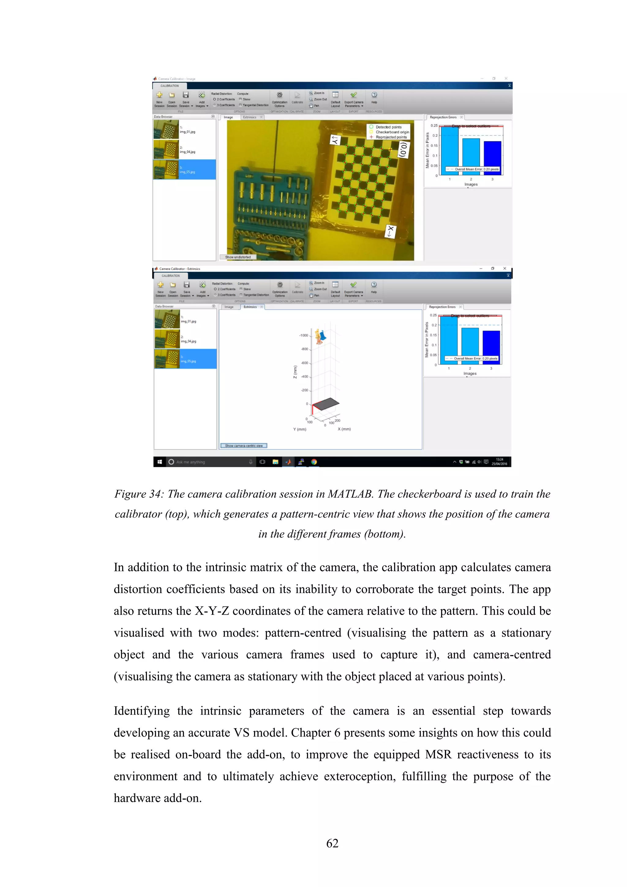
![64
Through designing the vision add-on using the techniques outlined, this research
proposes the first implementation of an MSR extension that utilises a Single-Board
Computer as its on-board controller. This adds many beneficial qualities to the add-on
which no other MSR add-on design has yet explored, to the extent of the research
conducted. The use of the SBC’s computational power not only allows much more
complex decision-making, but also more robust real-time data acquisition and more
powerful system-wide communication.
In addition, since MATLAB was chosen as the primary software development
environment for the add-on, a variety of powerful software packages could be readily
integrated and used on the add-on. This could be used to develop system-level control
strategies that govern the behaviour of the MSR as a whole. While this was not
demonstrated in practice, research was conducted into autonomous control design for
SBC-based robots implemented within Simulink [41]. It was attempted to implement
similar methods on-board the add-on; however, they could not be fully verified during
this project.
Both MATLAB and Simulink have immense potential to further benefit this add-on.
For instance, functionality to live-stream data to the Internet of Things (IoT), through
a package named ThingSpeak [42], was briefly investigated. In addition, the prospect
of controlling the entire add-on behaviour using these tools render them interesting
progression points for the overall project. This serves to remove many of the software
development constraints, as the user would be in full control of the controller model
developed, be it at the individual add-on scale, or its complete integration within the
system.
It is hoped that this research paves the way for potential expansions upon both the
HiGen and its add-ons, and this SBC-based add-on. Much of the ground has already
been covered in this development: it is up to the successor to steer this add-on, and
consequently the MSR as a whole, in the direction of real-world application.](https://image.slidesharecdn.com/ca626474-80ef-4230-a9c1-9d2dbef4c309-160828124550/75/Mohamed-Marei-120126864-Dissertation-Design-and-Construction-of-Hardware-Add-ons-for-a-Modular-Self-Reconfigurable-Robot-System-79-2048.jpg)

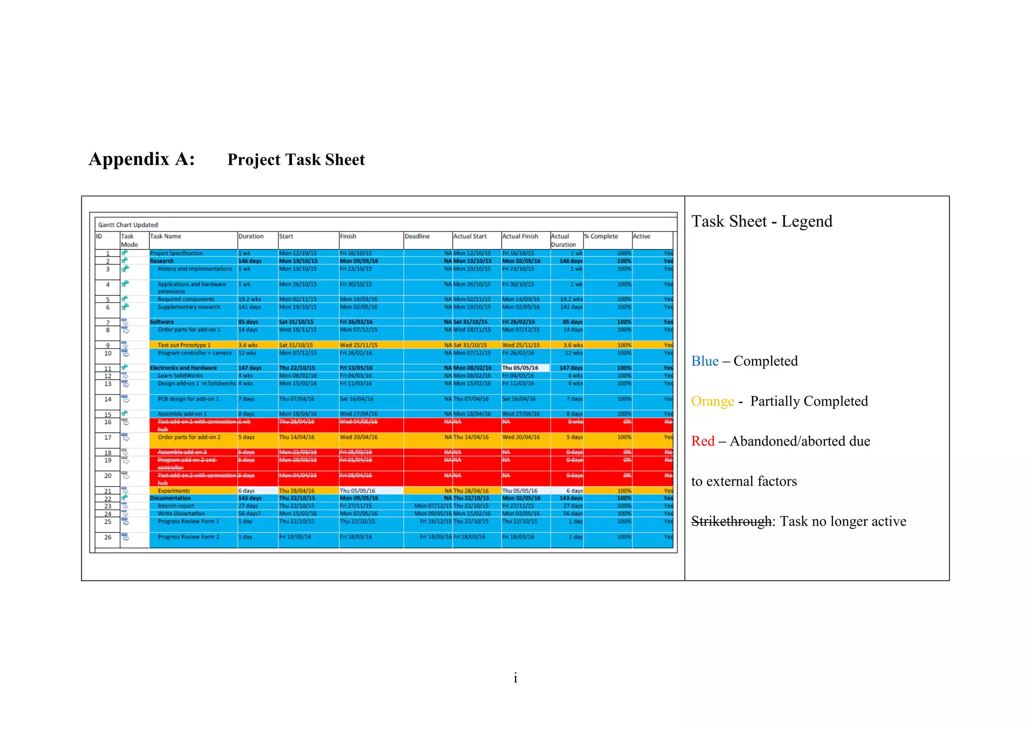
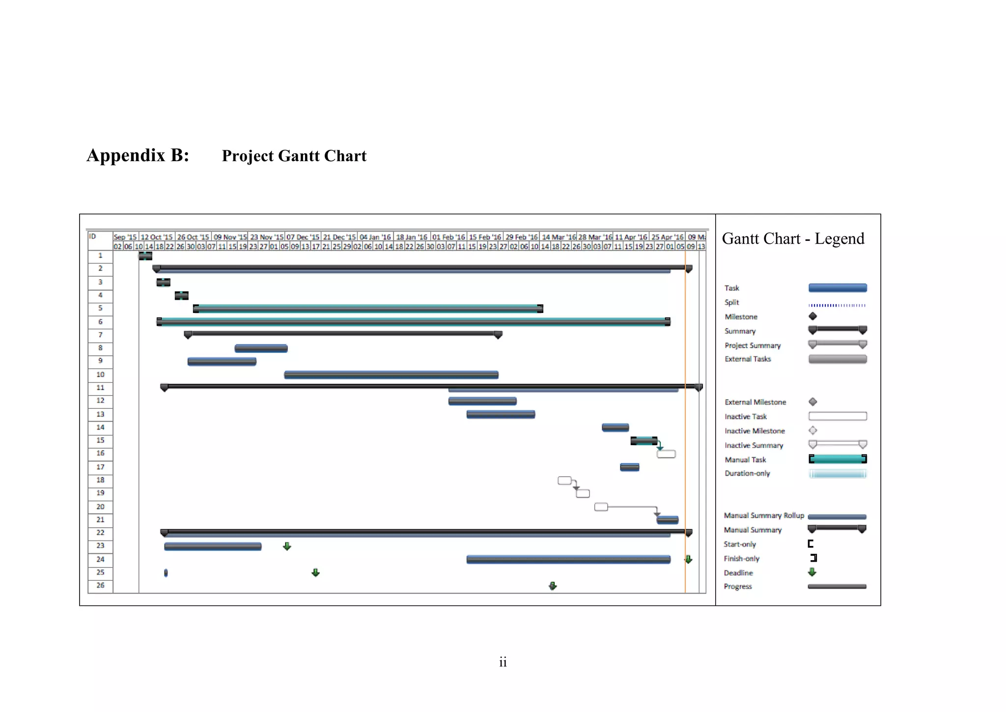
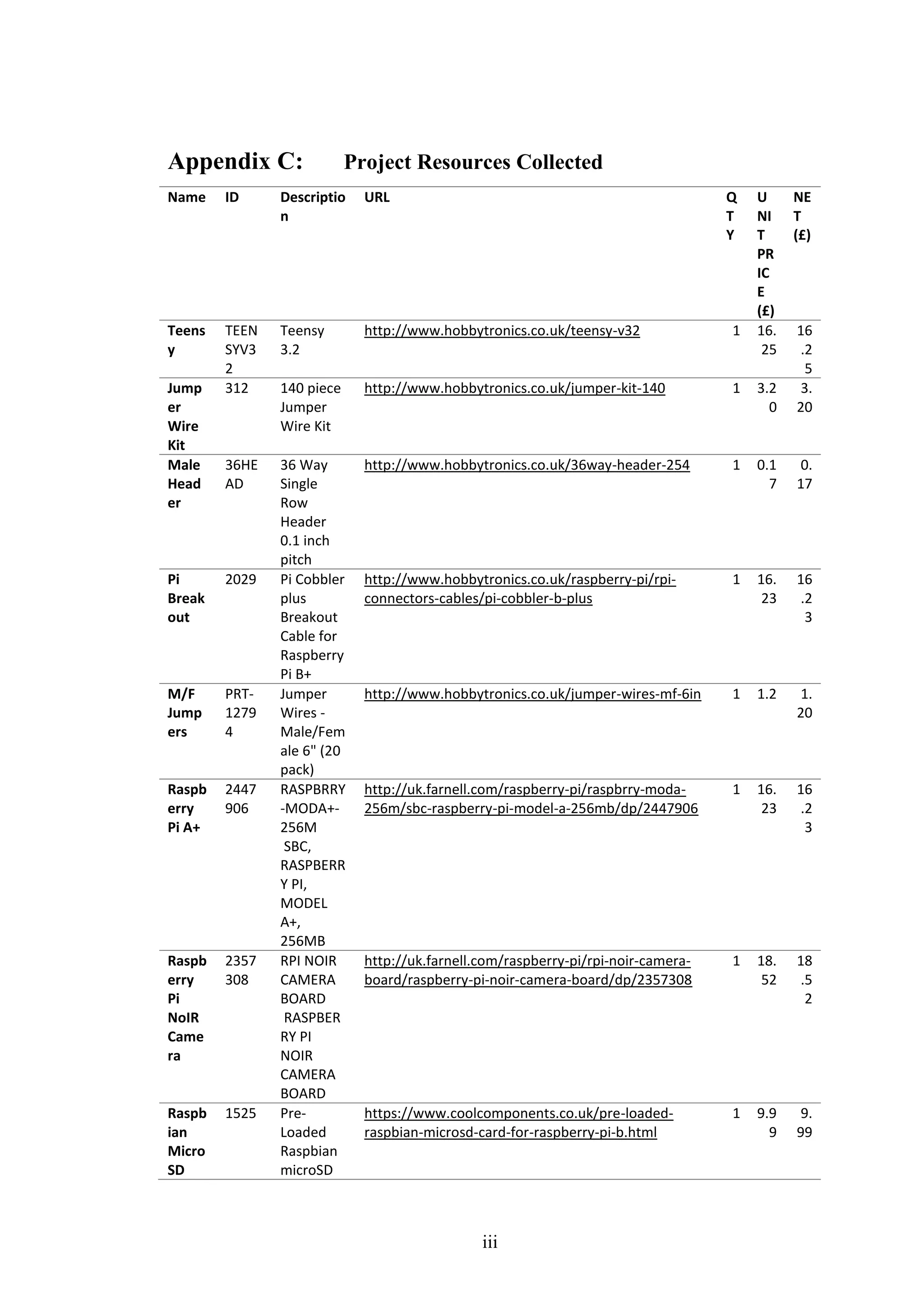
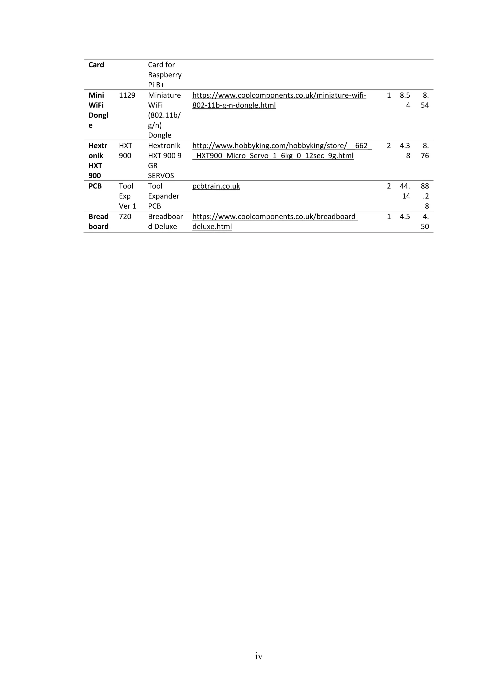
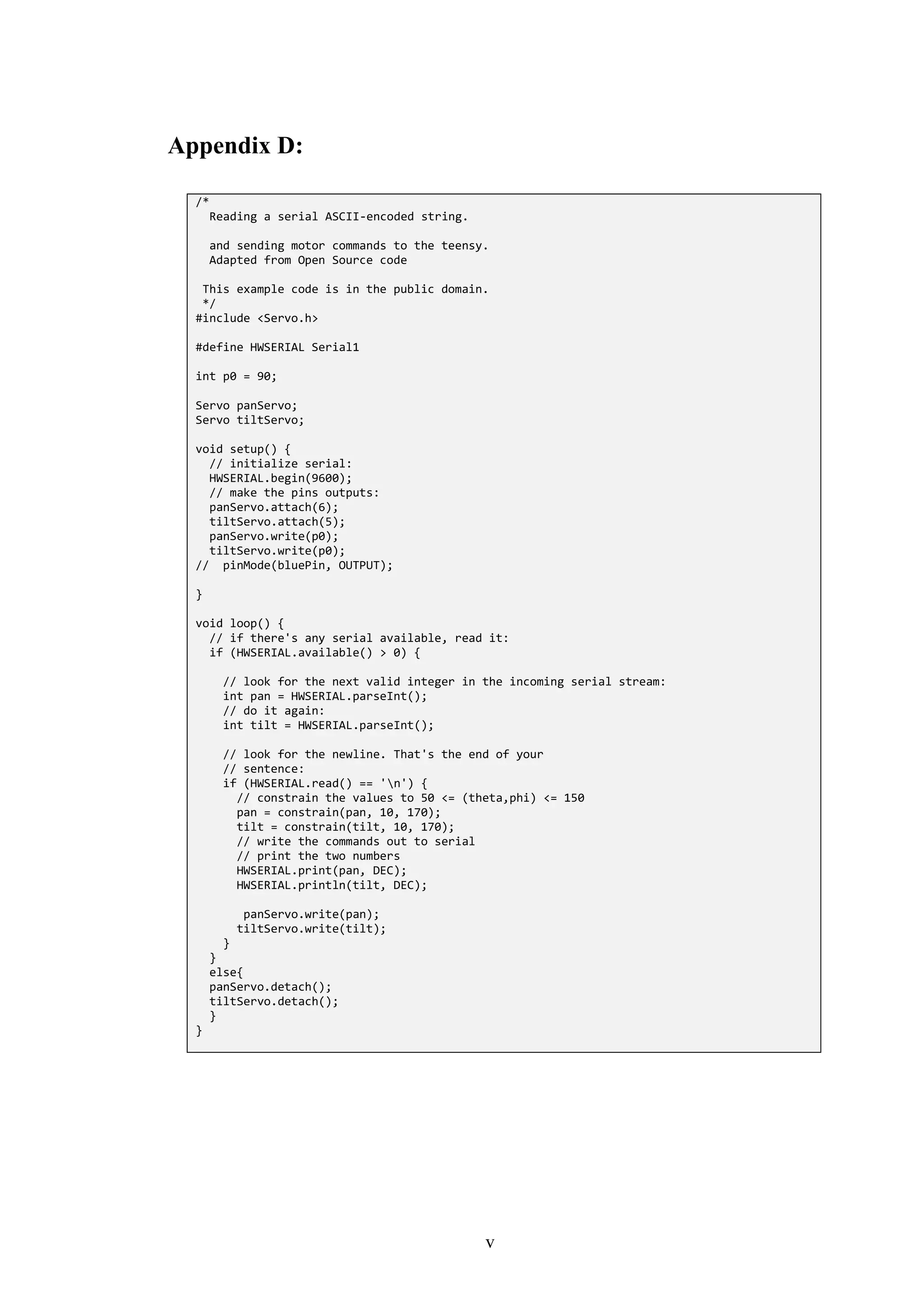
![vi
Appendix E: Source Code for Trackball
function [img, bw, xm, ym] = trackball_cpy(img, thresh)
r = img(:,:,1);
g = img(:,:,2);
b = img(:,:,3);
%% Calculate green
justGreen = g - r/2 - b/2;
%% Threshold the image
bw = justGreen > thresh;
%% Find center
[x, y] = find(bw);
if ~isempty(x) && ~isempty(y)
xm = round(mean(x));
ym = round(mean(y));
%% Creat a red dot
xx = max(1, xm-5):min(xm+5, size(bw, 1));
yy = max(1, ym-5):min(ym+5, size(bw, 2));
bwbw = zeros(size(bw), 'uint8');
bwbw(xx, yy) = 255;
%% Create output image
img(:,:,1) = uint8(r + bwbw);
img(:,:,2) = uint8(g - bwbw);
img(:,:,3) = uint8(b - bwbw);
xm = xm+0;
ym = ym+0;
else
xm = 0;
ym = 0;
end](https://image.slidesharecdn.com/ca626474-80ef-4230-a9c1-9d2dbef4c309-160828124550/75/Mohamed-Marei-120126864-Dissertation-Design-and-Construction-of-Hardware-Add-ons-for-a-Modular-Self-Reconfigurable-Robot-System-86-2048.jpg)
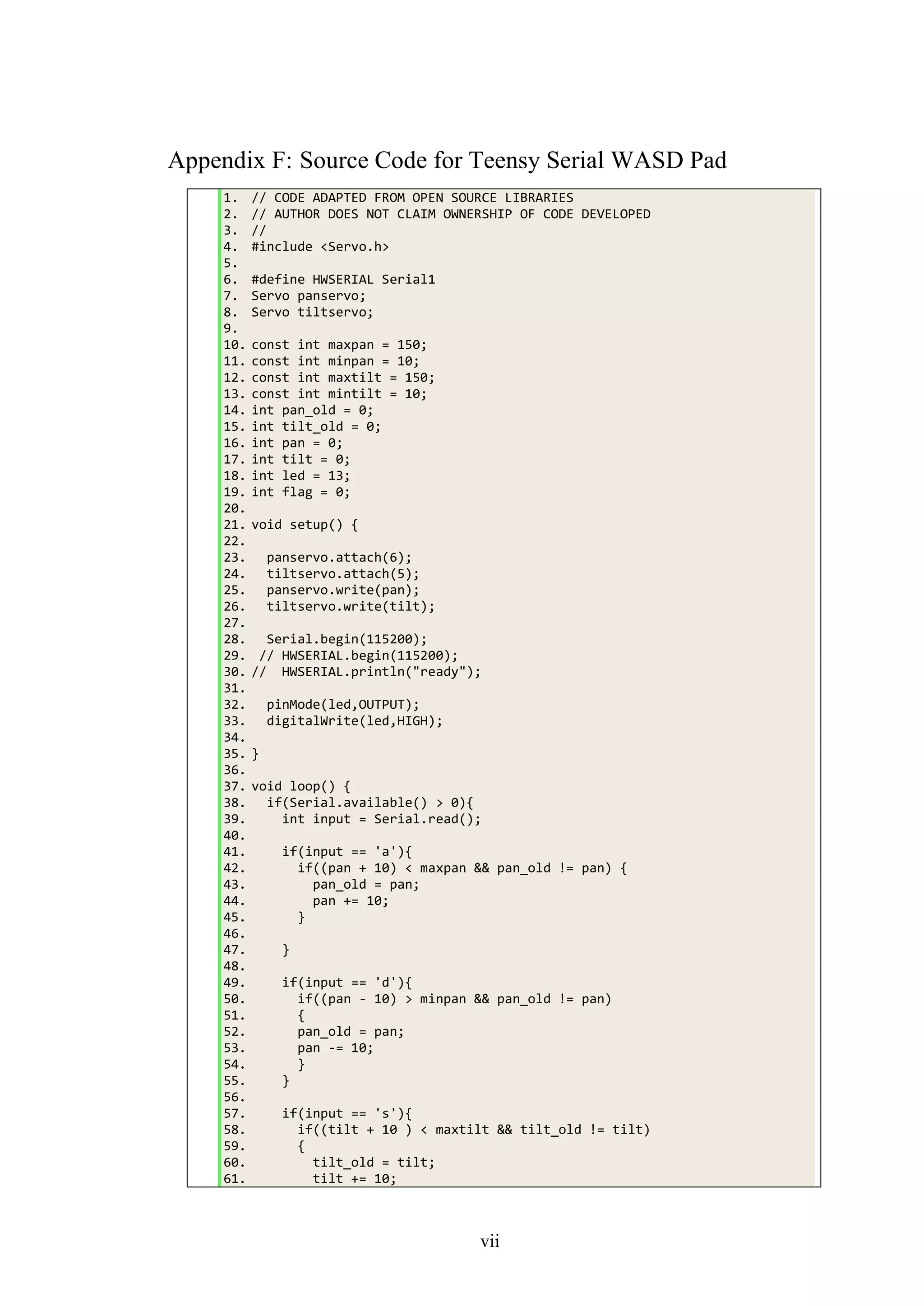
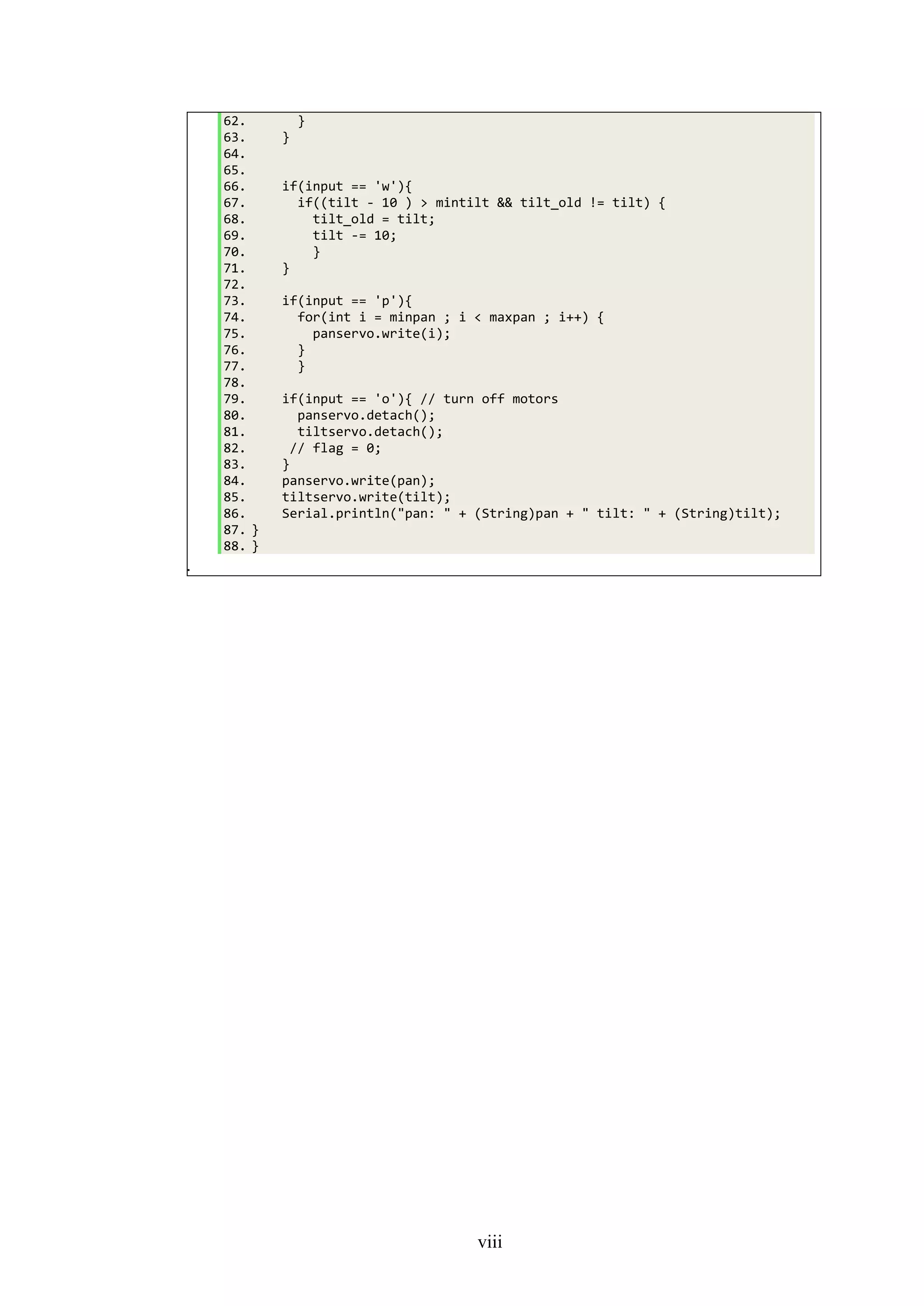
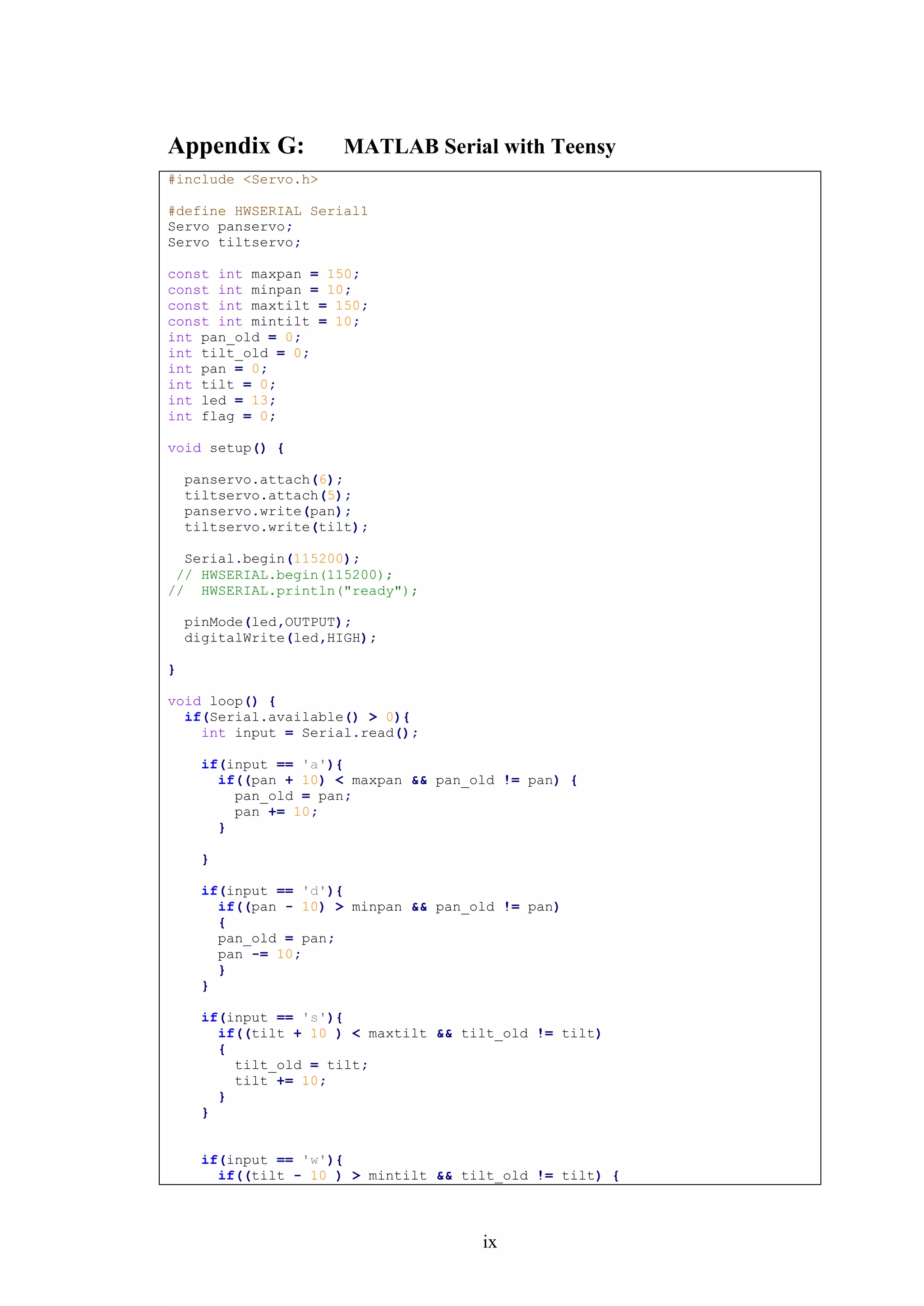
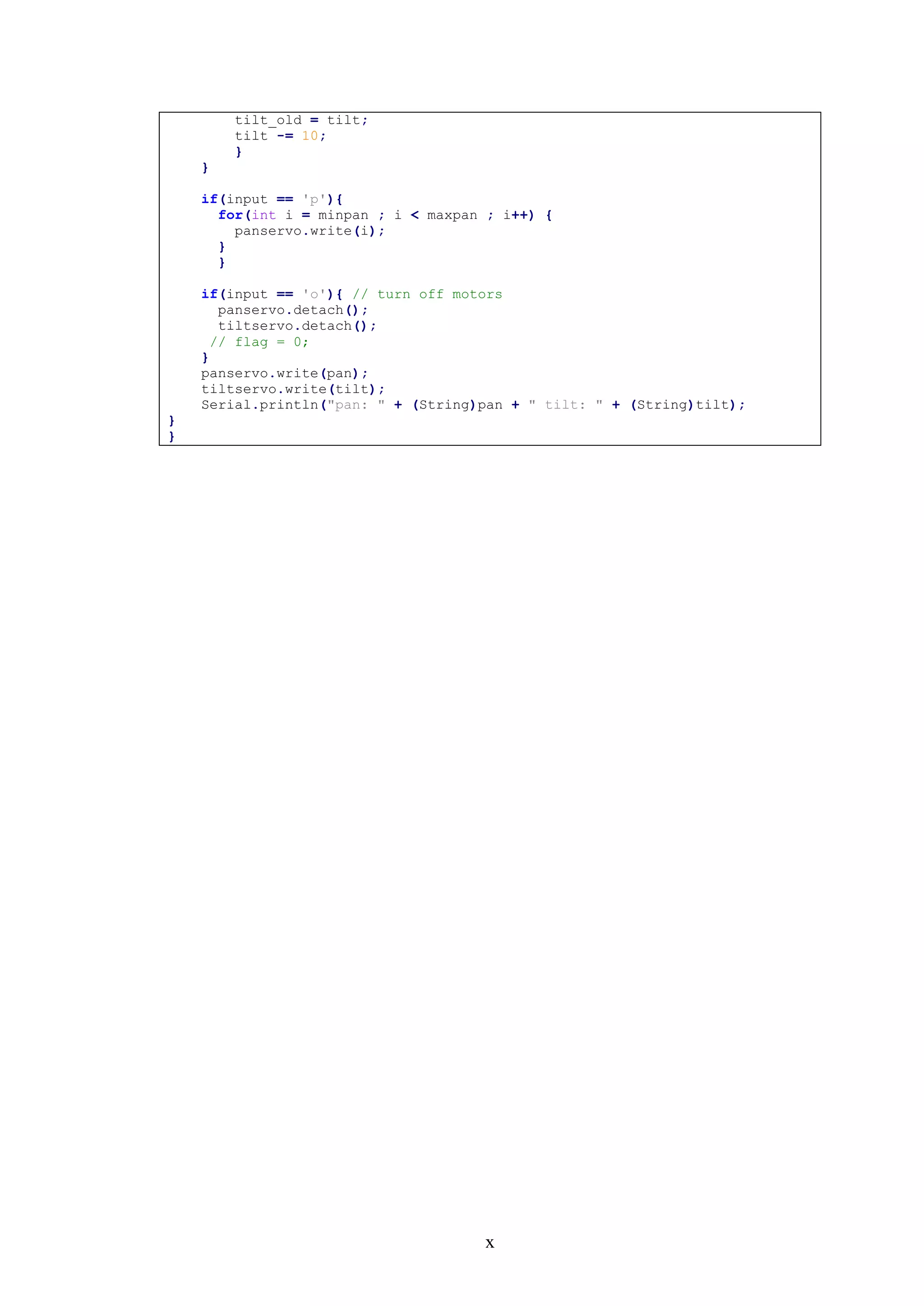
![xi
Appendix H: Pan-Tilt Model in MATLAB
% MATLAB MODEL OF PAN-TILT TRACKING
% Adapted from work by Chen et al.
% Mohamed Marei, 29/04/2016
function [theta,phi,rho,XYZ] = pan_tilt(u,v,theta_d,phi_d)
% Predefine n,r,alpha,w,h
n = 0.40; % left as a small value for now;
w = 320;
h = 240;
r = w/h;
alpha=deg2rad(41.4);
% Compute theta_d and phi_d, i.e. pan and tilt angles
tdp = - pi + deg2rad(theta_d) ;
pdp = pi/2 - deg2rad(phi_d);
% compute the angles
ctp = cos(tdp); % cos(theta-pi)
stp = sin(tdp); % sin(theta-pi)
cpp = cos(pdp); % cos(pi/2 - phi)
spp = sin(pdp); % sin(pi/2 - phi)
% Rotation matrix of theta about x-axis
Rxt = [1 0 0; % Rotation of theta-pi about x-axis;
i.e. a tilt motion
0 ctp -stp;
0 stp ctp];
% Rotation matrix of phi about z-axis
Rzp = [cpp -spp 0; % Rotation of pi/2-phi about z-axis; VT 1
spp cpp 0;
0 0 1];
% inverse of M_view
Mview = Rxt*Rzp;
Mview_inv= inv(Mview);
% Compute image information
xp_dd = 2*n*r*(-0.5+(u/w))*tan(0.5*alpha);
yp_dd = 2*n*(-0.5+(v/h))*tan(0.5*alpha);
zp_dd = -n;
% Compute point x,y,z
XYZ=Mview_inv*[xp_dd yp_dd zp_dd]';
X = XYZ(1);
Y = XYZ(2);
Z = XYZ(3);
theta = round(rad2deg(acos(Z/sqrt(X^2+Y^2+Z^2)))); % theta_d is
defined as the (tilt angle)
phi = round(rad2deg(atan(Y/X))); % phi_d is defined
as the pan angle
end](https://image.slidesharecdn.com/ca626474-80ef-4230-a9c1-9d2dbef4c309-160828124550/75/Mohamed-Marei-120126864-Dissertation-Design-and-Construction-of-Hardware-Add-ons-for-a-Modular-Self-Reconfigurable-Robot-System-91-2048.jpg)
![xii
Appendix I: Source Code for Simple Tracking Controller
1 % %% Simple code to track a green tennis ball, find its centre, then issue
2 % % motor commands from the Pi to an Arduino.
3 % % Created by Mohamed Marei on 05/04/2016
4 % clear mypi cam teensy
5 ip = '192.168.27.167'; % Raspberry Pi's IP address
6 usr = 'pi'; % Pi username
7 pswd = 'raspberry'; % Password
8 %
9 mypi = raspi(ip,usr,pswd); % initialises Pi object
10 cam = cameraboard(mypi, 'Resolution','640x480');% initialises camera object
11 if cam.Rotation == 0 % Ensure camera faces right
12 cam.Rotation = 180; % way up
13 end
14 % A simple loop to track the position of the ball throughout the
15 % figure(1); clf reset
16 cam = cameraboard(mypi,'Resolution','320x240','Quality',40,'Brightness',60)
17 tb =0;
18 pb =0;
19 time = [1:500];
20 tlen = length(time);
21 tb_delta = zeros(1,tlen);
22 pb_delta = zeros(1,tlen);
23 theta_array = zeros(1,tlen);
24 phi_array = zeros(1,tlen);
25 xm_array = zeros(1,tlen);
26 ym_array = zeros(1,tlen);
27 XYZ_array = zeros(3,tlen);
28 %teensy = serialdev(mypi,'dev/ttyAMA0',115200);
29 teensy = serial ('Com6','BaudRate', 9600);
30 % substitute for teensy = serial('Com6') with the same board parameters
31 u = 160 + 1.*rand(1,500);
32 v = 160 + 1.*rand(1,500);
33 %%
34 for i=1:tlen
35 [img, bw, xm, ym] = trackball_cpy(snapshot(cam),40);
36 figure(1);
37 subplot(211);
38 imagesc(img);
39 rectangle(‘Position’.[xm-30 ym-27 60 54])
40 subplot(212);
41 imagesc(bw);
42 drawnow;
43 pause(0.05)
44 % theta is the pan angle, phi is the tilt angle
45 [theta,phi,XYZ]=pan_tilt(u(i),v(i),tb,pb);
46 theta_array(i)=theta;
47 phi_array(i)=phi;
48 xm_array(i) = xm;
49 ym_array(i) = ym;
50 tb_delta(i) = (abs(theta)-abs(tb));
51 pb_delta(i) = (abs(phi)-abs(pb));
52 tb=theta;
53 pb=phi;
54 XYZ_array(:,i)=XYZ;
55 % IF THE NEW COORDINATES are larger than 0.5* the width of the rectangle,
56 % pan; similarly for tilt
57 if phi*0.32 < 160-u(i) || theta*0.32 < 120-v(i)
58 write(teensy,[pan tilt],'uint8') % sends pan and tilt angles to teensy
59 end
60 end
61 figure(2); clf reset;
62 subplot(2,1,1);
63 plot(time,xm_array);
64 xlabel('time (ms)');
65 ylabel('x (pixels)')
66 subplot(2,1,2);
67 plot(time,ym_array);](https://image.slidesharecdn.com/ca626474-80ef-4230-a9c1-9d2dbef4c309-160828124550/75/Mohamed-Marei-120126864-Dissertation-Design-and-Construction-of-Hardware-Add-ons-for-a-Modular-Self-Reconfigurable-Robot-System-92-2048.jpg)
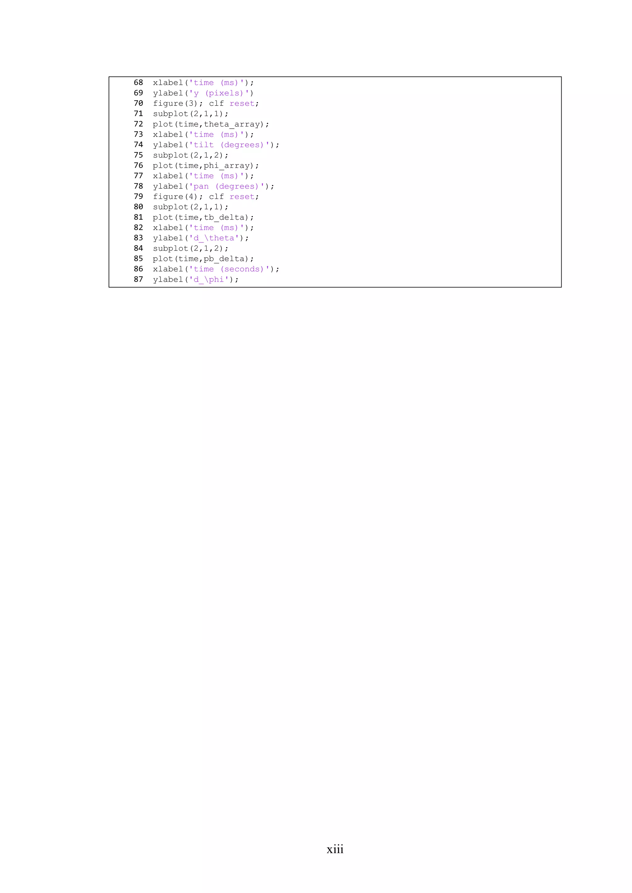
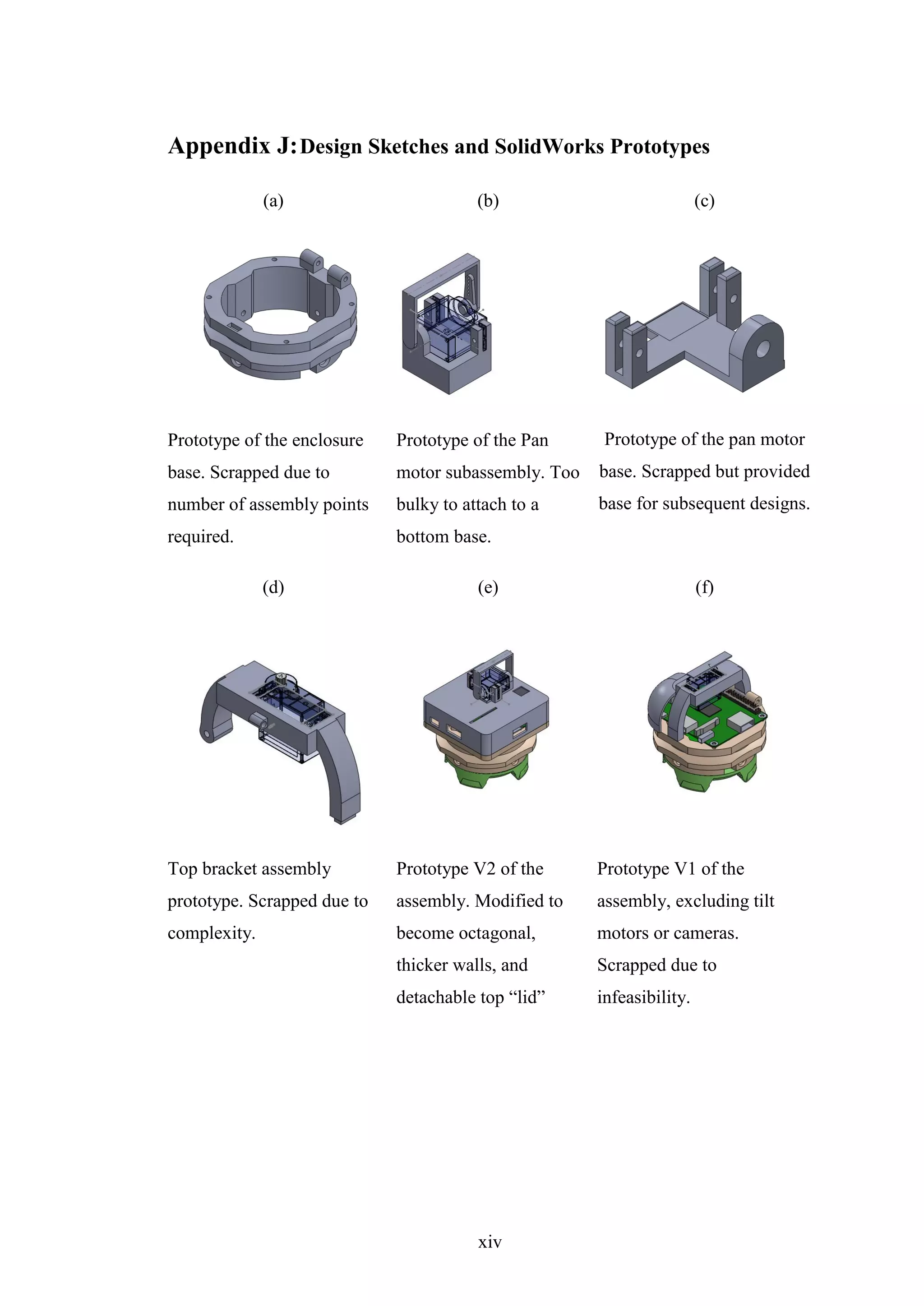
![xv
References
[1] K. Stoy, D. Brandt and D. J. Christiensen, Self-Reconfiguring Robots: An
Introduction, Cambridge, Massachusetts: The MIT Press, 2010.
[2] C. Parrott, T. J. Dodd and a. R. Groß, “HiGen: A high-speed genderless
mechanical connection mechanism with single-sided disconnect for self-
reconfigurable modular robots,” in IEEE/RSJ International Conference on
Intelligent Robots and Systems (IROS), Chicago, IL, 2014.
[3] T. Fukuda and S. Nakagawa, “Dynamically reconfigurable robotic system,”
Proc. IEEE Conf. Robotics and Automation, vol. 3, pp. 1581-1586, 1988.
[4] M. W. Jorgensen, E. H. Ostergaard and H. H. Lund, “Modular ATRON: Modules
of a Self-Reconfiguring Robot,” in IEEE/RSJ Int. Conf. on Robots and Systems,
Sendai, Japan, 2004.
[5] S. Murata, H. Kurokawa and S. Kokaji, “Self-assembling machine,” in Proc.
IEEE Int Conf. on Robotics and Automation, San Diego, CA, 1994.
[6] G. S. Chirikjian, “Kinematics of a metamorphic robotic system,” in Proc. 1994
IEEE Conf. Robotics and Automation, San Diego, CA, 1994.
[7] B. Salemi, M. Moll and W.-M. Shen, “SuperBot: A deployable, multi-functional,
and modular self-reconfigurable robotic system,” in IEEE/RSJ Intl. Conf. on
Intelligent Robots and Systems, Beijing, China, 2006.
[8] K. Kotay and D. Rus, “Locomotion versatility through self-reconfiguration,”
Robotics and Autonomous Systems, vol. 26, pp. 217-232, 1999.
[9] M. D. Kutzer, M. S. Moses, C. Y. Brown, D. H. Scheidt, G. S. Chirikjian and M.
Armand, “Design of a New Independently Mobile Reconfigurable Modular](https://image.slidesharecdn.com/ca626474-80ef-4230-a9c1-9d2dbef4c309-160828124550/75/Mohamed-Marei-120126864-Dissertation-Design-and-Construction-of-Hardware-Add-ons-for-a-Modular-Self-Reconfigurable-Robot-System-95-2048.jpg)
![xvi
Robot,” in IEEE International Conference on Robotics and Automation,
Anchorage, Alaska, 2010.
[10] J. Davey, N. Kwok and M. Yim, “Emulating Self-reconfigurable Robots - Design
of the SMORES System,” in 2012 IEEE/RSJ Intl. Conf. on Intelligent Robots and
Systems, Vilamoura, Algrave, Portugal, 2012.
[11] S. Murata, E. Yoshida, A. Kamimura, H. Kurokawa, K. Tonita and S. Kokaji,
“M-TRAN: Self-reconfigurable modular robotic system,” IEEE/ASME
Transactions on Mechatronics, vol. 7, no. 4, pp. 432-441, 2002.
[12] M. Yim, K. Roufas, D. Duff, Y. Zhang, C. Eldershaw and S. Homans, “Modular
Reconfigurable Robots in Space Applications,” Autonomous Robots, vol. 14, no.
(2-3), pp. 225-237, 2003.
[13] M. Yim, D. G. Duff and K. D. Roufas, “PolyBot: a modular reconfigurable
robot.,” in Proceedings of the IEEE Intl. Conf. on Robotics and Automation, San
Francisco, USA, 2000.
[14] E. Yoshida, S. Matura, A. Kamimura, K. Tomita, H. Kurokawa and S. & Kokaji,
“A self-reconfigurable modular robot: Reconfiguration planning and
experiments,” The International Journal of Robotics Research, vol. 21, no. 10-
11, pp. 903-915, 2002.
[15] A. Shokri and E. Masehian, “A meta-module approach for cluster flow
locomotion of modular robots,” in Robotics and Mechatronics (ICROM), 2015
3rd RSI International Conference on, 2015.
[16] K. &. N. R. Stoy, “Self-reconfiguration using directed growth,” in In Proc. 7th
Int. Symp. on Distributed Autonomous Robotic Systems., 2004.
[17] Unknown, “MODLAB - the modular robotics laboratory at the university of
pennsylvania,” MODLAB, 2012. [Online]. [Accessed 11 November 2015].
[18] R. Gross, M. Bonani, F. Monanda and M. Dorgio, “Autonomous self-assembly in
swarm-bots,” IEEE Transactions on Robotics, vol. 22, no. 6, pp. 1115-1130,](https://image.slidesharecdn.com/ca626474-80ef-4230-a9c1-9d2dbef4c309-160828124550/75/Mohamed-Marei-120126864-Dissertation-Design-and-Construction-of-Hardware-Add-ons-for-a-Modular-Self-Reconfigurable-Robot-System-96-2048.jpg)
![xvii
2006.
[19] K. Payne, J. Everist, F. Hou and W.-M. Shen, “Single-Sensor Probabilistic
Localization on the SeReS Self-Reconfigurable Robot,” IAS, 2006.
[20] S. Babak, C. J. Taylor, M. Yim, J. Sastra and M. Park, “Using smart cameras to
localize self-assembling modular robots,” Distributed Smart Cameras, 2007.
ICDSC'07. First ACM/IEEE International Conference on, pp. 76-80, 2007.
[21] B. Shirmohammadi, C. J. Taylor, M. Yim, J. Sastra and M. Park, “Towards
robotic self-reassembly after explosion,” Departmental Papers (MEAM), p. 147,
2007.
[22] A. Castano, A. Behar and P. M. Will, “The Conro Modules for Reconfigurable
Robots,” IEEE/ASME TRANSACTIONS ON MECHATRONICS, vol. 7, no. 4, p.
403, 2002.
[23] B. Li, S. Ma, J. Liu, M. Wang, T. Liu and Y. Wang, “AMOEBA-I: A Shape-
Shifting Modular Robot for Urban Search and Rescue,” Advanced Robotics, vol.
23, pp. 1025-1056, 2009.
[24] D. L. Akin, B. Roberts, S. Roderick, W. Smith and J.-M. Henriette,
“MORPHbots: Lightweight Modular Self-Reconfigurable Robotics for Space
Assembly, Inspection, and Servicing,” in Space, San Jose, California, 2006.
[25] A. Lyder, R. F. M. Garcia and K. Stoy, “Genderless connection mechanism for
modular robots introducing torque transmission between modules,” in
Proceedings of the ICRA Workshop on Modular Robots, State of the Art, 2010.
[26] M. Yim, W. M. Shen, B. Salemi, D. Rus, M. Moll, H. Lipson and G. S.
Chirikijian, “Modular self-reconfigurable robot systems [grand challenges of
robotics],” Robotics & Automation Magazine, IEEE, vol. 14, no. 1, pp. 43-52,
2007.
[27] I.-M. Chen, “Rapid response manufacturing through a rapidly reconfigurable
robotic workcell,” Robotics and Computer Integrated Manufacturing, vol. 17,](https://image.slidesharecdn.com/ca626474-80ef-4230-a9c1-9d2dbef4c309-160828124550/75/Mohamed-Marei-120126864-Dissertation-Design-and-Construction-of-Hardware-Add-ons-for-a-Modular-Self-Reconfigurable-Robot-System-97-2048.jpg)
![xviii
pp. 199-213, 2000.
[28] Y. Koren and M. Shpitalni, “Design of reconfigurable manufacturing systems,”
Journal of Manufacturing Systems, vol. 29, no. 4, pp. 130-141, 2010.
[29] C. Parrott, T. J. Dodd and R. Gross, “Towards A 3-DOF Mobile and
Reconfigurable Modular Robot,” 2014.
[30] G. Sims, “Showdown: Raspberry Pi 2 vs ODROID C1 vs HummingBoard vs
MIPS Creator CI20 (updated),” 30 04 2016. [Online]. Available:
http://www.androidauthority.com/raspberry-pi-2-vs-odroid-c1-vs-
hummingboard-vs-mips-creator-ci20-599418/.
[31] “Pi NoIR Camera,” The Raspberry Pi Foundation, 2014. [Online]. Available:
https://www.raspberrypi.org/products/pi-noir-camera/. [Accessed 24 November
2015].
[32] “Teensy USB Development Board,” PJRC, [Online]. Available:
https://www.pjrc.com/teensy/. [Accessed 12 December 2015].
[33] “Raspberry Pi Model A+ on Sale,” Raspberry Pi Foundation, November 2014.
[Online]. Available: https://www.raspberrypi.org/blog/raspberry-pi-model-a-
plus-on-sale/. [Accessed 11 November 2015].
[34] J. Drogon, “wiringPi,” wiringPi, none. [Online]. Available:
http://wiringpi.com/reference/serial-library/. [Accessed 26 January 2016].
[35] “OpenCV: an Open Source Computer Vision Library,” OpenCV, 2008. [Online].
Available: http://opencv.org/. [Accessed 11 February 2016].
[36] A. Rosebrock, “Install OpenCV and Python on your Raspberry Pi 2 and B+,”
PyImageSearch, [Online]. Available:
http://www.pyimagesearch.com/2015/02/23/install-opencv-and-python-on-your-
raspberry-pi-2-and-b/. [Accessed 11 February 2016].
[37] D. A. Forsyth and J. Ponce, Computer Vision: A Modern Approach, Essex:](https://image.slidesharecdn.com/ca626474-80ef-4230-a9c1-9d2dbef4c309-160828124550/75/Mohamed-Marei-120126864-Dissertation-Design-and-Construction-of-Hardware-Add-ons-for-a-Modular-Self-Reconfigurable-Robot-System-98-2048.jpg)
![xix
Pearson Education Limited, 2012.
[38] G. Chen, P. L. St-Charles, W. Bouachir, G. A. Bilodeau and R. & Bergevin,
“Reproducible Evaluation of Pan-Tilt-Zoom Tracking,” International Conference
on Image Processing (ICIP), pp. 2055-2059, 2015.
[39] F. Chaumette and S. Hutchinson, “24. Visual Servoing and Visual Tracking,” in
Springer Handbook of Robotics, Heidleberg, Germany, Springer-Verlag, 2008,
pp. 563-584.
[41] “Raspberry Pi Robot:,” MathWorks, 30 September 2014. [Online]. Available:
http://www.mathworks.com/matlabcentral/fileexchange/47376-control-a-
raspberry-pi-powered-robot-with-matlab-and-simulink. [Accessed 28 April
2016].
[42] “Internet of Things - ThingSpeak,” MathWorks, 2016. [Online]. Available:
https://thingspeak.com/. [Accessed 29 April 2016].](https://image.slidesharecdn.com/ca626474-80ef-4230-a9c1-9d2dbef4c309-160828124550/75/Mohamed-Marei-120126864-Dissertation-Design-and-Construction-of-Hardware-Add-ons-for-a-Modular-Self-Reconfigurable-Robot-System-99-2048.jpg)


