Module:5 Functional materials7 hours
❖ Composites - types and properties
❖ Polymers - thermosetting and thermoplastic polymers –
synthesis and application (TEFLON, BAKELITE)
❖ Conducting polymers- polyacetylene and effect of doping
❖ Chemistry of display devices specific to OLEDs
❖ Nanomaterials – introduction, bulk vs. nano (quantum dots)
❖ Top-down and bottom-up approaches for synthesis
3.
❑ A compositematerial is a combination of two
materials with different physical and chemical
properties.
❑ The materials combined to produce a new material
which is specific to a definite work, for instance, to
become stronger, lighter, or resistant to electricity and
also improve strength and stiffness.
❑ The components maintain their identity within the
composite, i.e. they do not dissolve or completely
merge into one another, though they act in concert.
What is a Composite Material?
4.
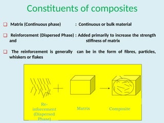
Constituents of composites
❑Matrix (Continuous phase) : Continuous or bulk material
❑ Reinforcement (Dispersed Phase) : Added primarily to increase the strength
and stiffness of matrix
❑ The reinforcement is generally can be in the form of fibres, particles,
whiskers or flakes
Reinforcement
Composite
Interface
Re-
inforcement
(Dispersed
Phase)
Matrix Composite
5.
Types of composites
NaturalComposites
(Exist in animal and
plants)
Wood = Cellulose +
Lignin
Bone= Hydroxyapatite
+ Collagen
(Man-Made)
Mud Bricks = Mud+
Straw
Reinforced Concrete
Fibre glass etc.
Synthetic composites
6.
Classification of
composite materials
Basedon the matrix
materials
Based on the
geometry of
reinforcement
⮚ Polymer matrix composite
(PMCs)
⮚ Metal Matrix composite (MMCs)
⮚ Ceramic matrix composite (CMCs)
⮚ Carbon/carbon composites (c/Cs)
⮚ Particulate reinforced composites
⮚ Whisker /Flakes reinforced
composites
⮚ Fibre reinforced composites
7.
7
Polymer matrix Composites
oPolymers constitute the most important matrix materials
and are used in more than 95% of the composite
products in use today.
Polymer
Resin
Thermosets
Thermoplastic
Elastomer
8.
8
Polymer matrix composites
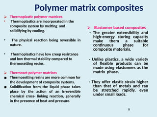
⮚Thermoplastic polymer matrices
• Thermoplastics are incorporated in the
composite system by melting and
solidifying by cooling.
• The physical reaction being reversible in
nature.
• Thermoplastics have low creep resistance
and low thermal stability compared to
thermosetting resins.
⮚ Thermoset polymer matrices
▪ Thermosetting resins are more common for
the development of composite systems.
▪ Solidification from the liquid phase takes
place by the action of an irreversible
chemical cross- linking reaction, generally
in the presence of heat and pressure.
⮚ Elastomer based composites
- The greater extensibility and
high-energy storing capacity
make them a suitable
continuous phase for
composite materials.
- Unlike plastics, a wide variety
of flexible products can be
made using elastomers as the
matrix phase.
- They offer elastic strain higher
than that of metals and can
be stretched rapidly, even
under small loads.
Metal- matrix composites(MMC)
❖ Metal Matrix Composites are composed of a metallic matrix (Al,Mg,Fe,Cu
etc) and a dispersed ceramic (oxide, carbides) or metallic phase( Pb,Mo,W
etc).
❖ Ceramic reinforcement may be silicon carbide, boron, alumina, silicon
nitride, boron carbide, boron nitride etc.,whereas metallic reinforcement
may be tungsten, beryllium etc.
❖ From a material point of view, when compared to polymer matrix
composites, the advantages of MMCs lie in their retention of strength and
stiffness at elevated temperature, good abrasion and creep resistance
properties.
❖ Most MMCs are still in the development stage or the early stages of
production and are not so widely established as polymer matrix composites.
The biggest disadvantages of MMCs are their high costs of fabrication.
❖ There are also advantages in some of the physical attributes of MMCs such
as no significant moisture absorption properties, non-inflammability and
resistance to most radiations.
11.
Metal- matrix composites(MMC)
❖ Only light metals are responsive, with their low density proving an advantage.
Titanium, aluminium and magnesium are the popular matrix metals currently
in vogue, which are particularly useful for aircraft applications.
❖ If metallic matrix materials have to offer high strength, they require high
modulus reinforcements.
❖ The strength-to-weight ratios of resulting composites can be higher than most
alloys.
❖ The melting point, physical and mechanical properties of the composite at
various temperatures determine the service temperature of composites.
❖ They can withstand elevated temperature in corrosive environment than
polymer composites. However, practically, the choices for low temperature
applications are not many.
❖ The choice of reinforcements becomes more stunted with increase in the
melting temperature of matrix materials.
12.
o Carbide drillsare often made from a tough cobalt
matrix with hard tungsten carbide particles inside.
o Modern high-performance sport cars, such as those
built by Porsche, use rotors made of carbon fiber
within a silicon carbide matrix.
o Metal Matrix Composite (MMC) are used in Diesel
Piston, disk break
o The F-16 Fighting Falcon uses monofilament silicon
carbide fibres in a titanium matrix for a structural
component of the jet's landing gear.
o Today these applications are found most often in
aircraft components, space systems and high-end
or "boutique" sports equipment.
o MMCs are used for Space Shuttle, commercial
airliners, electronic substrates, bicycles,
automobiles, golf clubs and a variety of other
applications.
Applications of Metal matrix composites (MMC)
Diesel Piston
Cast Brake
Disk
13.
Ceramic Matrix composite(CMC)
o A given ceramic matrix can be reinforced with either
discontinuous reinforcements, such as particles, whiskers
or chopped fibres, particulates having compositions of
Si3N4, SiC, AlN, titanium diboride, boron carbide, and
boron nitride or with continuous fibres.
o Characteristics of CMC
❖ High-temperature stability
❖ High thermal shock resistance
❖ High hardness
❖ High corrosion resistance
❖ Light weight
❖ Nonmagnetic and nonconductive properties
❖ Versatility in providing unique engineering solutions
14.
Applications:
❖ CMCs findpromising applications in the area of cutting tools and in
heat engines where the components should withstand aggressive
environments.
❖ In Aircraft engines - use of stator vanes formed of CMC in the hot
section of the F136 turbofan engine is under consideration.
15.
Applications of CMC
•Ceramic-matrix composites are now also commercially available as brake rotors
for automobiles.
✔ The new Porsche braking system uses an MMC brake pad.
✔ Ceramic-matrix composite brake rotors have also been demonstrated for the
Inter-City Express high-speed trains in Germany, where a total weight savings of
5.5 metric tons is obtained per train set.
16.
Basic terms inpolymer science
Polymer : Polymers are complex and giant molecules which are
made from joining a large number of small and simple molecules
by primary valency linkage.
Monomer : The individual small and simple molecules from which
the polymer is formed are known as monomer.
Polymerization : The process by which the monomer molecules
are linked to form a big polymer molecule is called polymerization.
ABS (Acrylonitrile-Butadine-Styrene)
• ADVANTAGES:
•Good impact resistance with toughness and rigidity
• Metal coatings have excellent adhesion to ABS
• Formed by conventional thermoplastic methods
• A light-weight plastic
DISADVANTAGES AND LIMITATIONS:
• Poor solvent resistance
• Low dielectric strength
• Only low elongations available
• Low continuous service temperature
TYPICAL ENGINEERING APPLICATIONS:
• Automotive hardware (used in electroplated metal coatings for
decorative hardware), appliance cases, pipe, plated items.
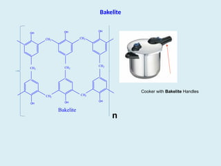
Properties and Applicationsof Bakelite
Properties
1. Bakelite is resistant to acids, salts and most organic solvents, but it
is attacked by alkalis because of the presence of –OH groups
2. It possesses excellent electrical insulating property
Applications
3. Bakelite is used as an adhesive in plywood laminations, grinding
wheels etc.
4. It is also widely used in paints, varnishes, decorative articles like
plates, drinking glasses, dishes etc.
5. It is used for making electrical insulator parts like plugs, switches,
heater handles etc.,
21.
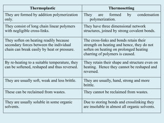
Thermoplastic Thermosetting
They areformed by addition polymerization
only.
They are formed by condensation
polymerization.
They consist of long chain linear polymers
with negligible cross-links.
They have three dimensional network
structures, joined by strong covalent bonds.
They soften on heating readily because
secondary forces between the individual
chain can break easily by heat or pressure.
The cross-links and bonds retain their
strength on heating and hence, they do not
soften on heating on prolonged heating
charring of polymers is caused.
By re-heating to a suitable temperature, they
can be softened, reshaped and thus reversed.
They retain their shape and structure even on
heating. Hence they cannot be reshaped and
reversed.
They are usually soft, weak and less brittle. They are usually, hand, strong and more
brittle.
These can be reclaimed from wastes. They cannot be reclaimed from wastes.
They are usually soluble in some organic
solvents.
Due to storing bonds and crosslinking they
are insoluble in almost all organic solvents.
Conducting Polymers
A conductingpolymer is an organic based polymer
that can act as a semiconductor or a conductor.
The most widely studied organic polymers are
Polyacetylene, polyaniline (PANI), polypyrroles,
polythiophenes, and polyphenylene vinylenes.
24.
Conducting polymers (CPs)are extensively conjugated
molecules: they have alternating single and double bonds. In
these molecules, electrons are able to move from one end of the
polymer to the other through the extended p-orbital system.
Hence CPs are known to be either semiconductors or
conductors giving them unique optical and electrical properties.
Most polymers are poor conductors due to non-availability of
large number of free electrons in the conduction process.
However, conducting polymers are synthesized which possess
electrical Conductivity similar to metal conductors.
Different Types:
(1) Intrinsically conducting polymers (ICP)
(2) Doped Conducting polymers
(3) Extrinsically conducting polymers (ECP)
25.
Factors that affectthe conductivity
1. Density of charge carriers
2. Their mobility
3. The direction
4. Presence of doping materials (additives that
facilitate the polymer conductivity in a better
way)
5. Temperature
26.
1. Intrinsically ConductingPolymers
Polymer consisting of alternating single and double bonds
is called conjugated double bonds.
In conjugation, the bonds between the carbon atoms are
alternately single and double. Every bond contains a
localised “sigma” (σ) bond which forms a strong chemical
bond.
In addition, every double bond also contains a less
strongly localised “pi” (π) bond which is weaker.
Conjugation of sigma and pi-electrons over the entire
backbone, forms valence bands and conduction bands.
Eg: Poly-acetylene polymers like poly-p-phenylene,
polyaniline, polypyrrole
27.
2. Doped ConductingPolymers
It is obtained by exposing a polymer to a charge transfer agent in
either gas phase or in solution. ICPs possess low conductivity
(10-10
/Ohm.cm), but they possess low ionisation potential and high
electron affinity. So they can be easily oxidised or reduced.
DOPING:
The conductivity of ICP can be increased by creating positive charges
(oxidation) or by negative charges (reduction) on the polymer
backbone. This technique is called DOPING .
In otherwords….
The polymer structure has to be disturbed - either by
removing electrons from (oxidation), or inserting them into
(reduction), the material. The process is known as Doping.
There are two types of doping:
1. Oxidation with halogen (or p-doping).
2. Reduction with alkali metal (called n-doping).
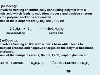
28.
) p-Doping:
involves treatingan intrinsically conducting polymer with a
ewis acid which leads to oxidation process and positive charges
n the polymer backbone are created.
ome of the p-dopants are I2, Br2, AsF5, PF5 etc.
2(C2H2)n + 3I2 2[(C2H2)n
+
I3
-
polyacetylene Lewis acid
i) n-Doping:
involves treating an ICP with a Lewis base which leads to
duction process and negative charges on the polymer backbone
e created.
ome of the n-dopants are Li, Na, Ca, FeCl3, naphthylamine etc.
_
…-CH=CH-CH=CH-… + C10H7NH2 …-CH=CH-CH=CH- + C10H8
I
+
NH
29.
3. Extrinsically ConductingPolymers
These are those polymers whose conductivity is due to the presence of
externally added ingredients in them.
Two types:
(1)Conductive element filled polymer:
It is a resin/polymer filled with carbon black, metallic fibres, metal
oxides etc. Polymer acts as a binder to those elements.
These have good bulk conductivity and are low in cost, light weight,
strong and durable. They can be in different forms, shapes and sizes.
(2) Blended Conducting Polymers:
It is product obtained by blending a conventional polymer with a
conducting polymer either by physical or by chemical change.
Such polymers can be processed and possess better physical,
chemical and mechanical strength.
Chemistry of displaydevices specific to OLEDs
An organic light-emitting diode (OLED or organic LED), also known
as organic electroluminescent (organic EL) diode, is a light-emitting diode
(LED) in which the emissive electroluminescent (EL) layer is a film of organic
compound that emits light in response to an electric current.
32.
Working principle ofOLEDs
⮚ The holes lie in the valence band, while the free electrons are in the conduction
band of material.
⮚ When there is a forward bias in the p-n junction, the electron which is a part of the
n-type semiconductor material would overrun the p-n junction and join with the
holes in the p-type semiconductor material. Therefore, regarding the holes, the free
electrons would be at the higher energy bands.
⮚ When this movement of free electron and hole takes place, there is a change in the
energy level as the voltage drops from the conduction band to the valance band.
⮚ There is a release of energy due to the motion of the electron.
⮚ In standard diodes, the release of energy in the manner of heat. But in LED the
release of energy in the form of photons would emit light energy.
⮚ This entire process is known as electroluminescence, and the diodes are known
as a light-emitting diode.
33.
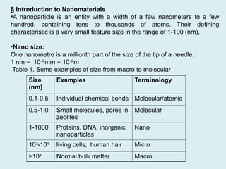
§ Introduction toNanomaterials
•A nanoparticle is an entity with a width of a few nanometers to a few
hundred, containing tens to thousands of atoms. Their defining
characteristic is a very small feature size in the range of 1-100 (nm).
•Nano size:
One nanometre is a millionth part of the size of the tip of a needle.
1 nm = 10-6
mm = 10-9
m
Table 1. Some examples of size from macro to molecular
Size
(nm)
Examples Terminology
0.1-0.5 Individual chemical bonds Molecular/atomic
0.5-1.0 Small molecules, pores in
zeolites
Molecular
1-1000 Proteins, DNA, inorganic
nanoparticles
Nano
103
-104
living cells, human hair Micro
>104
Normal bulk matter Macro
Size and shapedependent colors of Au and Ag nanoparticles
25 nm
Sphere
reflected
50 nm
Sphere
reflected
100 nm
Sphere
reflected
100 nm
Sphere
reflected
40 nm
Sphere
reflected
100 nm
prism
reflected
Gold NPs in Glass Silver NPs in Glass
35
36.
Size and shapedependent colors of Au and Ag nanoparticles
Note: nanomaterials scatter visible light rather than absorb
⮚ Distance between particles also effects colour
Surface plasmon resonance: Excitation of surface plasmons by light (visible
or infra red) is denoted as a surface plasmon resonance
Localized surface plasmon resonance (LSPR) for nanometer-sized metallic structures
36
37.
Quantum dots (QDs)are semiconductor particles of few nanometers (<10
nm) in size, having optical and electronic properties that differ from larger
particles.
Quantum Dots and applications
5
n
m
Cancer cell imaging Metal ions sensing Light emitting diode
38.
38
Emission properties ofQuantum Dots
1. Band gap decreases as the QDs size increases
2. Emission wavelength becomes red shifted with increase in size of QDs
39.
•Nanomaterials show unusual
⮚Mechanical
⮚ Electrical
⮚ Optical
⮚ Magnetic properties.
Hence it has potential applications in
⮚ Different industries
⮚ Biomedical
⮚ Electronic applications.
⮚ For example, long lasting medical implants of
biocompatible nanostructured ceramic and
carbides,
⮚ Biocompatible coating
⮚ Drug delivery
⮚ Protection coatings
⮚ Composite materials
⮚ Anti fogging coatings for spectacles and car
windows etc.
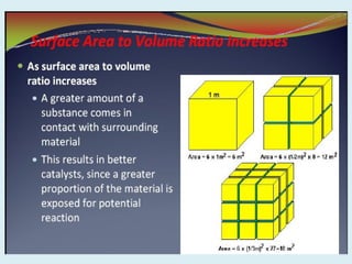
40.
⮚ Deviation fromthe reduced size and dimensionality of the nanometer-sized
building blocks (crystallites), the numerous interfaces between adjacent
crystallites, grain boundaries and surfaces
⮚ These building blocks have different crystallographic orientation that may
lead to incoherent or coherent interfaces between them
⮚ Lead to inherent heterogeneous structure on a nanometer scale.
⮚ Grain boundaries make up a major portion of the material at nanoscales,
and strongly affect properties and processing.
⮚ Surfaces and interfaces- half or more than half atoms near to interfaces
⮚ Hence, surface properties such as energy levels, electronic structure,
and reactivity are different from bulk materials
What makes these nanomaterials so different and so intriguing?
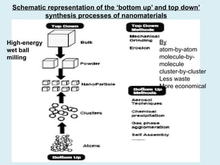
Schematic representation ofthe ‘bottom up’ and top down’
synthesis processes of nanomaterials
High-energy
wet ball
milling
By
atom-by-atom
molecule-by-
molecule
cluster-by-cluster
Less waste
More economical
44.
❖ Top-down approaches
⮚High-energy ball milling/Machining
⮚ Chemical Oxidation Process (CNTs to QDs)
⮚ Electrochemical Oxidation Process (Graphite rod to QDs)
⮚ Lithography (photo- and electrochemical)
⮚ Etching/Cutting
⮚ Coating
⮚ Atomization
❖Bottom-up approaches
⮚Gas Condensation Processing (GCP)/AerosolBased Processes
⮚ Chemical Vapour Condensation (CVC)
⮚ Atomic or Molecular Condensation
⮚ Laser ablation
⮚ Supercritical Fluid Synthesis
⮚Wet Chemical Synthesis of nanomaterials (Sol-gel process)
⮚ Precipitation method
⮚ Spinning
⮚ Self-Assembly
⮚ DNA Origami
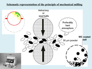
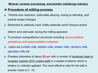
Nanoparticles preparation:
❖ Procedure ofmilling process
⮚ Particle size reduction, solid-state alloying, mixing or blending, and
particle shape changes
⮚ Restricted to relatively hard, brittle materials which fracture and/or
deform and cold weld during the milling operation
⮚ To produce nonequilibrium structures including nanocrystalline,
amorphous and quasicrystalline materials
⮚ Users are tumbler mills, attrition mills, shaker mills, vibratory mills,
planetary mills etc
⮚ Powders diameters of about 50 µm with a number of hardened steel or
tungsten carbide (WC) coated balls in a sealed container which is
shaken or violently agitated. The most effective ratio for the ball to
powder mass is 5 : 10.
Mineral, ceramic processing, and powder metallurgy industry
47.
• Shaker mills(e.g. SPEX model 8000) uses small batches of powder
(approximately 10 cm3
is sufficient
❖ Advantage: High production rates
❖ Limitation
⮚ Severe plastic deformation associated with mechanical attrition due to
generation of high temp in the interphase, 100 to 200 o
C.
⮚ Difficulty in broken down to the required particle size
⮚ Contamination by the milling tools (Fe) and atmosphere (trace
elements of O2, N2 in rare gases) can be a problem (inert condition
necessary like Glove Box)(Fe <1-2% and Trace elements<300 ppm)
⮚ Protective coating to reduce milling tools contamination (MTC)
increases cost of the process
⮚ Working duration (>30 h) increases MTC (>10%)
49.
• Sol/gel transitioncontrols the particle size and shape. Calcination of
the gel produces the product (eg. Oxide).
• Sol-gel processing > hydrolysis and condensation of alkoxide-based
precursors such as Si(OEt)4 (tetraethyl orthosilicate, or TEOS).
• The reactions are as follows:
MOR + H2O → MOH + ROH (hydrolysis)
MOH+ROM→M-O-M+ROH (condensation)
• If the aging process of gels exceeds 7 days it is critical to prevent the
cracks in gels that have been cast
• Steps are:
Sol Gel Ageing Drying Dehydration
Densification & Decomposition Product
51.
❖ Advantages
• Synthesizingnonmetallic inorganic materials like glasses, glass
ceramics or ceramic materials at very low temperatures compared
to melting glass or firing ceramics
• Monosized nanoparticles possible by this bottom up approach.
❖ Disadvantages
• Controlling the growth of the particles and then stopping the newly formed
particles from agglomerating.
• Difficult to ensure complete reaction so that no unwanted reactant is left on the
product
• Completely removal of any growth aids
• Also production rates of nanopowders are very slow by this process