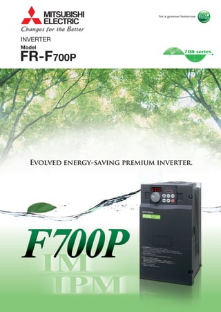
Mitsubishi inverter freqrol-f700 p series
•
0 likes•89 views

Mitsubishi , Catalog Thiết Bị Điện Mitsubishi , Catalog Thiết Bị Điện Catalog Phụ Kiện Mitsubishi , Catalog Phụ Kiện, Catalog Mitsubishi , Catalog, https://www.dienhathe.com, Chi tiết các sản phẩm khác của Mitsubishi tại https://dienhathe.com Xem thêm các Catalog khác của Mitsubishi tại https://dienhathe.info Để nhận báo giá sản phẩm Mitsubishi vui lòng gọi: 0907.764.966
![•Features
•Standard
specs
•Outline
dimensions
•Operation panel
•Parameter unit
•FR Configurator
•Parameter list
•Parameter
details
•Protective
functions
•Options and
peripheral devices
•Precaution on
selection and operation
•Precautions on
peripheral device
selection
•Compatible
motor
•IPM motor
control
•Difference and
compatibility with
FR-F500 (L) series
•Price and
delivery time
•Warranty
•Global FA centers
•Connection
examples
1
7
8
12
24
27
97
31
39
64
66
80
86
92
96
•Terminal connection
diagrams
•Terminal specs
IPM parameter initialization
IM and IPM driven
by one inverter
First, replace
inverters.
Next, replace
motors.
65
70
75
80
85
90
95
100
0.75 1.5 2.2 3.7 5.5 7.5 11 15 18.5 22 30 37 45 55
Before Now… Future
Equipment Investment in Stages
Inverter
Inverter
Drive unit Premium inverter
Drive unit
Spare inverters for both One spare inverter
Renewal
completed!
1st Stage
2nd Stage
PREMIUM INVERTER F700P
The Next-Generation "F700P Inverter for Fans and Pumps" for Reducing CO2 Emissions
(1) IE4-equivalent efficiency level
(1) The F700P series inverter can drive both a general-purpose motor (IM) and an IPM motor (IPM).
GThe IM driving setting can be switched to IPM driving setting by only one setting
"12" (MM-EFS) in the parameter . (Refer to page 92 for details.)
Never drive an IPM motor in the IM drive setting.
GOne spare F700P inverter is enough for the two types of motors (IM and IPM);
the number of required spare inverters is reduced by half.
(2) Simple and reliable transition from IM to IPM
GThere is no need to replace the whole system at once;
replace the inverters first, then replace the motors.
When the budget is limited, equipment investment can be
made over several stages.
General-purpose motor (induction motor)IPM motor (synchronous motor)
Rotor conductor
(copper or aluminum)
Stator core
Shaft
Rotor core
Stator coil
(three-phase coil)
Stator coil
(three-phase coil)
Permanent
magnets
Shaft
Stator core
Rotor core
*Example of
6-pole motor
N
S
S
N
N
S
N
S
S
N
S
N
Stator core
Rotor core
Permanent magnet
Stator coil
*1: Rated motor output is 100%.
GThe consumed power of a variable-torque load, such as
fans, pumps, and blowers, is proportional to the cube of its
rotation speed.
This means that controlling the rotation speed to adjust the air volume
can lead to energy savings.
GA high-efficiency IPM motor "MM-EF series"
is equivalent to IE3 (premium efficiency).
A premium high-efficiency IPM motor
"MM-EFS series" provides even better
efficiency that is equivalent to IE4 (super
premium efficiency), the highest efficiency
class*.
(2) Smooth replacement from a general-purpose motor (with the same installation size)
GThe frame number is the same (same size) as the
Mitsubishi general-purpose motors (4-pole SF-JR/SF-HR
series). Replacement is easy as the installation sizes are
compatible. (55kW or lower)
Motor structure (section view)
(1) Energy saving with speed control
GOptimum excitation control continuously adjusts the excitation
current to an optimum level to provide the highest motor
efficiency, and that leads to substantial energy savings. (Refer to
page 47 for the details.)
At 10% motor load torque, for example, the motor efficiency under Optimum
excitation control is about 15% higher than the motor efficiency under
conventional V/F control.
(2) Energy saving with Optimum
excitation control (General-purpose motors)
GHigh efficiency achieved with IPM motors
•The IPM motors that have permanent magnets embedded in their rotors
are even more efficient than the high-performance energy-saving motors.
GWhy is an IPM motor more efficient?
•No current flows to the rotor (secondary side), and no secondary copper
loss is generated.
•Magnetic flux is generated with permanent magnets, and less motor current is required.
•Embedded magnets provide reluctance torque*2, and the reluctance torque
can be applied.
GWhat is an IPM motor?
An IPM motor is a synchronous
motor with strong permanent
magnets embedded in its rotor.
*2: Reluctance torque
Reluctance torque occurs due to magnetic imbalance on the rotor.
(3) Energy saving with IPM motors
Inverters for Dramatic Energy Saving
0 20
20
40
40
60
60
80
80
100
100 Optimum excitation control
More energy saving
V/F control
Motor load torque (%) Driving IM and IPM Brings So Many Benefits
Same size
SF-JR 3.7kW MM-EFS371M4
IEC 60034-30
Efficiency class
Efficiency of Mitsubishi motors
General-purpose motor IPM motor
IE4
(super premium efficiency)*
IE3 (premium efficiency)
IE2 (high efficiency)
IE1 (standard efficiency)
Below the class
Standard three-phase
motor (SF-JR)
Premium high-efficiency
IPM (MM-EFS)
High-efficiency IPM
(MM-EF)
High-performance energy-
saving motor (SF-HR)
*: The details of IE4 can be found in IEC 60034-31.
*As of October 2012
The "F700P inverter for fans and pumps"
can drive both general-purpose motors
(3-phase induction motors) and IPM
motors. The F700P could be the
solution to your energy saving needs.
Energy
saving
IM&IPM
[Example of blower operation characteristic]
20
40
60
120
0
80
100
40 60 80 100
*1
Consumedpower(%)
Motorefficiency(%)
Damper control
High-performance
energy-saving
motor driven with inverter
Premium high-efficiency
IPM motor driven with inverter
General-purpose motor
driven with inverter
Air volume (%)
[Comparison of Mitsubishi products]
[Comparison of Mitsubishi products]
[Comparison of efficiency]
Motor capacity (kW) [Comparison of Mitsubishi products]
General-purpose motor
driven with inverter
High-performance energy-saving
motor driven with inverter
High-efficiency IPM motor
driven with inverter
Premium high-efficiency IPM
motor driven with inverter
Totalefficiency(%)
* Example of 22kW motors
[ Comparison of motor losses ]
100%
Primary copper
loss
Iron loss
Other
Iron loss
Primary copper
loss (stator side)
Secondary copper
loss (rotor side)
Other
General-purpose motor
60%
Primary copper
loss
Iron loss
Other
Premium high-efficiency
IPM motor
High-efficiency
IPM motor
40%
SF-JR MM-EF MM-EFS
Premium
high-efficiency
IPM motorMM-EFS Series
HighEfficiencyLow
IPM motor (MM-EFS)
To Save More Energy — the MM-EFS Series is Now Available
1 2](data:image/gif;base64,R0lGODlhAQABAIAAAAAAAP///yH5BAEAAAAALAAAAAABAAEAAAIBRAA7)
Recommended
Recommended
More Related Content
Similar to Mitsubishi inverter freqrol-f700 p series
Similar to Mitsubishi inverter freqrol-f700 p series (20)
More from Dien Ha The
More from Dien Ha The (20)
Recently uploaded
Recently uploaded (20)
Mitsubishi inverter freqrol-f700 p series
- 2. •Features •Standard specs •Outline dimensions •Operation panel •Parameter unit •FR Configurator •Parameter list •Parameter details •Protective functions •Options and peripheral devices •Precaution on selection and operation •Precautions on peripheral device selection •Compatible motor •IPM motor control •Difference and compatibility with FR-F500 (L) series •Price and delivery time •Warranty •Global FA centers •Connection examples 1 7 8 12 24 27 97 31 39 64 66 80 86 92 96 •Terminal connection diagrams •Terminal specs IPM parameter initialization IM and IPM driven by one inverter First, replace inverters. Next, replace motors. 65 70 75 80 85 90 95 100 0.75 1.5 2.2 3.7 5.5 7.5 11 15 18.5 22 30 37 45 55 Before Now… Future Equipment Investment in Stages Inverter Inverter Drive unit Premium inverter Drive unit Spare inverters for both One spare inverter Renewal completed! 1st Stage 2nd Stage PREMIUM INVERTER F700P The Next-Generation "F700P Inverter for Fans and Pumps" for Reducing CO2 Emissions (1) IE4-equivalent efficiency level (1) The F700P series inverter can drive both a general-purpose motor (IM) and an IPM motor (IPM). GThe IM driving setting can be switched to IPM driving setting by only one setting "12" (MM-EFS) in the parameter . (Refer to page 92 for details.) Never drive an IPM motor in the IM drive setting. GOne spare F700P inverter is enough for the two types of motors (IM and IPM); the number of required spare inverters is reduced by half. (2) Simple and reliable transition from IM to IPM GThere is no need to replace the whole system at once; replace the inverters first, then replace the motors. When the budget is limited, equipment investment can be made over several stages. General-purpose motor (induction motor)IPM motor (synchronous motor) Rotor conductor (copper or aluminum) Stator core Shaft Rotor core Stator coil (three-phase coil) Stator coil (three-phase coil) Permanent magnets Shaft Stator core Rotor core *Example of 6-pole motor N S S N N S N S S N S N Stator core Rotor core Permanent magnet Stator coil *1: Rated motor output is 100%. GThe consumed power of a variable-torque load, such as fans, pumps, and blowers, is proportional to the cube of its rotation speed. This means that controlling the rotation speed to adjust the air volume can lead to energy savings. GA high-efficiency IPM motor "MM-EF series" is equivalent to IE3 (premium efficiency). A premium high-efficiency IPM motor "MM-EFS series" provides even better efficiency that is equivalent to IE4 (super premium efficiency), the highest efficiency class*. (2) Smooth replacement from a general-purpose motor (with the same installation size) GThe frame number is the same (same size) as the Mitsubishi general-purpose motors (4-pole SF-JR/SF-HR series). Replacement is easy as the installation sizes are compatible. (55kW or lower) Motor structure (section view) (1) Energy saving with speed control GOptimum excitation control continuously adjusts the excitation current to an optimum level to provide the highest motor efficiency, and that leads to substantial energy savings. (Refer to page 47 for the details.) At 10% motor load torque, for example, the motor efficiency under Optimum excitation control is about 15% higher than the motor efficiency under conventional V/F control. (2) Energy saving with Optimum excitation control (General-purpose motors) GHigh efficiency achieved with IPM motors •The IPM motors that have permanent magnets embedded in their rotors are even more efficient than the high-performance energy-saving motors. GWhy is an IPM motor more efficient? •No current flows to the rotor (secondary side), and no secondary copper loss is generated. •Magnetic flux is generated with permanent magnets, and less motor current is required. •Embedded magnets provide reluctance torque*2, and the reluctance torque can be applied. GWhat is an IPM motor? An IPM motor is a synchronous motor with strong permanent magnets embedded in its rotor. *2: Reluctance torque Reluctance torque occurs due to magnetic imbalance on the rotor. (3) Energy saving with IPM motors Inverters for Dramatic Energy Saving 0 20 20 40 40 60 60 80 80 100 100 Optimum excitation control More energy saving V/F control Motor load torque (%) Driving IM and IPM Brings So Many Benefits Same size SF-JR 3.7kW MM-EFS371M4 IEC 60034-30 Efficiency class Efficiency of Mitsubishi motors General-purpose motor IPM motor IE4 (super premium efficiency)* IE3 (premium efficiency) IE2 (high efficiency) IE1 (standard efficiency) Below the class Standard three-phase motor (SF-JR) Premium high-efficiency IPM (MM-EFS) High-efficiency IPM (MM-EF) High-performance energy- saving motor (SF-HR) *: The details of IE4 can be found in IEC 60034-31. *As of October 2012 The "F700P inverter for fans and pumps" can drive both general-purpose motors (3-phase induction motors) and IPM motors. The F700P could be the solution to your energy saving needs. Energy saving IM&IPM [Example of blower operation characteristic] 20 40 60 120 0 80 100 40 60 80 100 *1 Consumedpower(%) Motorefficiency(%) Damper control High-performance energy-saving motor driven with inverter Premium high-efficiency IPM motor driven with inverter General-purpose motor driven with inverter Air volume (%) [Comparison of Mitsubishi products] [Comparison of Mitsubishi products] [Comparison of efficiency] Motor capacity (kW) [Comparison of Mitsubishi products] General-purpose motor driven with inverter High-performance energy-saving motor driven with inverter High-efficiency IPM motor driven with inverter Premium high-efficiency IPM motor driven with inverter Totalefficiency(%) * Example of 22kW motors [ Comparison of motor losses ] 100% Primary copper loss Iron loss Other Iron loss Primary copper loss (stator side) Secondary copper loss (rotor side) Other General-purpose motor 60% Primary copper loss Iron loss Other Premium high-efficiency IPM motor High-efficiency IPM motor 40% SF-JR MM-EF MM-EFS Premium high-efficiency IPM motorMM-EFS Series HighEfficiencyLow IPM motor (MM-EFS) To Save More Energy — the MM-EFS Series is Now Available 1 2
- 3. PREMIUM INVERTER F700P 55K or lower 75K or higher Capacitive filter Standard (built-in) Standard (built-in) Common mode choke Standard (built-in) Option (sold separately) DC reactor Option (sold separately) Standard (accessory) AC reactor (FR-HAL) DC reactor (FR-HEL) Inverter Inverter Terminating resistor Terminating resistorCC-Link dedicated cable CC-Link Network FR-A7NC FR-A7NC (when connecting only inverters) Max. 42 units connectableMaster stationCPU Power supply module PLC RS-485 terminal block RS-485 terminal block Pr.7 Acceleration time Set frequency Base frequency Pr.8 Deceleration time GVariable torque loads such as fans and blowers can be accelerated/decelerated in a short period of time. (Available with general-purpose motors) (1) Variable-torque acceleration/deceleration pattern GThe service life of the cooling fans is now 10 years*1. The service life can be further extended by ON/OFF control of the cooling fan. GCapacitors with a design life of 10 years*1*2 are adapted. (Using a surrounding air temperature of 105ºC for 5000 hours). With these capacitors, the service life of the inverter is further extended.) *1: Surrounding air temperature: Annual average of 40ºC (free from corrosive gas, flammable gas, oil mist, dust and dirt). The design life is a calculated value and is not a guaranteed product life. *2: Output current: 80% of the inverter rating. (1) Longer life parts (3) Hands-free maintenance GDetachable operation panel GParameter copy with operation panel GRemovable terminal blocks GEasy wiring with comb-shaped wiring cover GReplaceable cooling fan (4) Easier work GThe degree of deterioration of the main circuit capacitor, control circuit capacitor, and inrush current limit circuit can be diagnosed on the monitor. GUsing the self-diagnosis function, the part life warning*3 can be output. With these warnings, the self-diagnosis function prevents troubles from occurring. *3: A warning is output when any of the main circuit capacitor, control circuit capacitor, inrush current limit circuit, and cooling fan reaches its output level. (2) The leading-edge life diagnosis function GOperation can be easily performed with the popular Mitsubishi setting dial. (1) Operation panel equipped with the setting dial (3) Easy setting from personal computer with FR Configurator GSimple parameter setting (Pr.79 Operation mode selection) GCommunication setting for Mitsubishi HMI (GOT) GRated frequency change (60Hz ¡ 50Hz) GUnit change in acceleration/deceleration time setting (0.1s ¡ 0.01s) (2) Automatic parameter setting specific to the application (1) RS-485 terminal block equipped as standard GLONWORKS®, CC-Link Ver.1.1, Ver.2.0, CC-Link IE Field, DeviceNet™, PROFIBUS-DP, FL Remote are supported through communication options. (2) Main international network protocols supported GAutomatic restart after instantaneous power failure function / flying start function. After an instantaneous power failure, the operation is re-startable from the coasting motor speed. Even if the rotation direction has been forcibly reversed, the operation can be smoothly restarted in the original direction. GPower failure time deceleration-to-stop function. During operations of fans and blowers, the operation is continued at an instantaneous power failure without the motor coasting*1. *1: The inverter may trip and coast the motor under some load conditions. (6) Keep running during instantaneous power failure GThe operation frequency is automatically increased to prevent the regenerative overvoltage fault from occurring. This function is useful when a load is forcibly rotated by another fan in the duct. (7) Regeneration avoidance function GVibration caused by mechanical resonance can be suppressed. (Available with general-purpose motors) (8) Mechanical resonance suppression (speed smoothing) GSimple magnetic flux vector control enables the high torque*2 generation in a low-speed operation range. This function is useful for a pump application, which requires large starting torque. (Available with general-purpose motors) *2: Up to 120% torque at 3Hz is generatable in combination with the slip compensation function. (9) Simple magnetic flux vector control GThe energy saving effect can be checked on the energy saving monitor. GThe measured output power amount can be output in pulses. (10) Energy saving effect checked at a glance GTo save energy in low-speed operation: PID output shutoff (sleep) function GTo shorten the start-up time of PID control: PID automatic switchover function GFor air conditioning applications: Forward/reverse rotation switching by external signals GTo use various types of detectors: PID set point and measured value outputs in voltage (0 to 5V / 0 to 10V) and current (4 to 20mA) (2) Full-scale PID function GContact input (12 terminals), analog input (3 terminals), open collector output (5 terminals), relay output (2 terminals), analog output, and pulse train output come standard. Various functions can be assigned to these terminals. GVoltage and current are selectable for analog input. GON/OFF status of the signals inputted to or outputted from the I/O terminals can be displayed on the operation panel. (3) Complete I/O terminals come standard GA frequency where the acceleration/deceleration time is changed can be pre-set; an external switch is not required to switch the time setting. This function is especially useful for an operation that requires high torque in a low speed operation. (4) Automatic acceleration/deceleration time switchover GParameter writing/reading can be restricted with a 4-digit password. This function is useful to prevent parameter values from being rewritten by misoperation. (5) Password function GBeing RoHS compliant, the FR-700P series inverters are friendly to people and the environment. (1) Compliance with the Restriction of the Use of Certain Hazardous Substances in Electrical and Electronic Equipment (RoHS Directive) in Europe GHarmonic current may adversely affect the power supply. To suppress such harmonic current, the power-factor-improving compact AC reactor (FR-HAL) and the DC reactor (FR-HEL) are available. (A DC reactor is provided for the 75K or higher as standard.) GThe F700P series inverters (55K or lower) are equipped with built-in capacitive filters and common mode chokes. By installing only an optional DC reactor (FR-HEL), they can conform to the Architectural Standard Specifications (Electric Installation) and Architectural Standard Specifications (Machinery Installation) (year 2009) issued by the Ministry of Land, Infrastructure, Transport and Tourism of Japan. (3) Harmonic current suppression GBy attaching the EMC filter connector to the ON or OFF position, the built-in EMC filter can be set enabled/disabled*1*2. When it is enabled, the inverter conforms to the EMC Directive (EN61800-3/2nd Environment Category C3*3) by itself. *1: Leakage current is higher when the EMC filter is enabled. *2: The EMC filter is always enabled for the 200V 0.75K and 1.5K inverters of which leakage current is generally low. (No connector is provided for these models.) The common mode choke installed at the input side of the 55K- or lower-capacity inverter is always enabled and unaffected by the ON/OFF status of the EMC filter connector. *2: Refer to the EMC Installation Guidelines for the required specification. (2) EMI suppression (equipped with the EMC filter) Cooling Fan GInverter operations from start-up to maintenance are easily performed. GParameter settings can be printed or saved in a file. A file containing the FR-F700 parameter settings can be exported to an FR-F700P series inverter. GThe conversion function allows parameter copy from an FR-F500 inverter to FR-F700P. Parameter list GA RS-485 terminal block is equipped separately from the PU connector. Multi-drop connection can be easily performed with separate input and output terminals. GThe newly added "Multi-command Mode" of Mitsubishi inverter protocol cuts down the data processing time of the inverter from 1/3 to 1/4. GThe F700P inverters support Modbus-RTU (binary) protocol in addition to the conventional Mitsubishi inverter protocol. GThe 32-bit cumulative power monitor enables monitoring of a large cumulative power amount without letting it overflow. Automatic restart after instantaneous power failure function Power failure time deceleration-to-stop function Removable terminal block GA fault can be initiated by setting a parameter. This function is useful to check how the system operates at a fault. GThe maintenance timer output function notifies the user about the maintenance time of peripheral devices. Introducing the Mitsubishi magnetic contactor GSelection of small frames GWide line-up of safety contactors GLow level load (auxiliary contact) supported GConformed to many international standards Refer to page 78 for the selection. Various Functions for Fans and Pumps Long Life and Simple Maintenance Easy Operation Environmentally Friendly Reinforced EMI measures Best Combination Easy & trouble-free Supporting More Network Protocols Extensibility Time Decelerates during instantaneous power failure (operation continued) Coasts during instantaneous power failure Easy FeaturesOptionsPrecautionsMotors Connection examples Standard specs Outline dimensions Parameter list Parameter descriptions Protective functions IPMmotor control Compatibility PriceWarranty/Inquiry Terminalconnection diagrams Terminalspecs Operationpanel Parameterunit FRConfigurator 3 4 Set frequency Pr.147 setting Time Output frequency(Hz) Slope set by Pr.8 Slope set by Pr.44 (Pr.45) Slope set by Pr.44 Slope set by Pr.7 Acceleration time Deceleration time
- 4. PREMIUM INVERTER F700P G: Available –: Not available G GGGGGGGGGGGGGFR-F740P-K G GGGGGGGGGGGGG 75 5004504003553152802502201851601321109045 5537302218.515117.55.53.72.21.50.75 Inverter model Three-phase 400V Power supply specification –––––––––––GG GFR-F720P-K G GGGGGGGGGGGGG – Three-phase 200V G 560 Precautions •Never drive an IPM motor in the IM drive setting. •Use the same IPM motor capacity as the inverter capacity. •For IPM motor, use an MM-EFS or MM-EF series motor. Please contact us regarding a combination with other manufacturer's IPM motor. How Much CO2 Emission Is Reduced? LINE UPLess CO2 The longer the operating period with medium air volume is, the higher energy saving effect obtained with an inverter. (Conditions: The electricity cost is 14 yen/kWh. The CO2 emission is 1,000kWh 0.555ton - CO2 emission) (Annual) energy saving effect produced by replacing to IPM motors driven with inverters Operation patterns Condition GWith commercial power supply Approx. 0.15 million kWh Approx. 2.17 million yen GWith inverter Approx. 0.14 million kWh Approx. 1.9 million yen [Units to drive] GWater-cooling pump 3.7kW × 1 unit GFans for the cooling tower 1.5kW × 1 unit GFreezer 11kW × 3 unit 5.5kW × 2 unit 3.7kW × 1 unit 3.0kW × 1 unit [Units to drive] GAnnual energy saving effect (differences in the amount and cost) GAnnual CO2 emission reduction GWith general-purpose motor Approx. 2.39 million kWh Approx. 33.42 million yen GWith IPM motor Approx. 2.1 million kWh Approx. 29.43 million yen GAnnual energy saving effect GAnnual CO2 emission reduction GWith general-purpose motor Approx. 0.25 million kWh Approx. 3.44 million yen GWith IPM motor Approx. 0.22 million kWh Approx. 3.02 million yen GAnnual energy saving effect GAnnual CO2 emission reduction 8760 hours/year 5110 hours/year5475 hours/year Water-cooling pump for a showcase + +Inverter General-purpose motor (SF-JR) Commercial power supply (valve) General-purpose motor (SF-JR) + +Inverter IPM motor (MM-EFS) Inverter General-purpose motor (SF-JR) Air conditioning in a Mitsubishi plant + +Inverter IPM motor (MM-EFS) Inverter General-purpose motor (SF-JR) Air conditioning in a building GVentilator 0.75kW × 3 unit 1.5kW × 1 unit 2.2kW × 3 unit GAir conditioner 15kW × 1 unit 18.5kW × 1 unit 30kW × 2 unit [Units to drive] GFans for air conditioning 5.5kW × 10 unit 7.5kW × 10 unit 3.7kW × 100 unit Air volume (%) Time 80 60 40 0 86 10 18 2021 Water volume (%) Time 100 75 50 25 WinterSpring Summer Fall Your best assistant — Mitsubishi inverter software GIPM energy savings simulation file The IPM energy savings simulation file calculates the energy saving effect and CO2 reduction rate achieved by replacing commercial power supply (damper/valve control) operation with IPM motor operation by inverter. This file requires inputs of motor capacity, quantity, air volume, operating time, etc. GFR Configurator (Option) (FR-SW3-SETUP-WE) Support tool for the inverter operations from start-up to maintenance. IPM energy savings simulation file Air volume (%) Time 100 80 50 0 6 9 12 15 18 21 24 GInverter F R - F 7 2 0 P - 3.7K 2 4 Symbol Voltage class 200V class 400V class 0.75K to 560K Symbol Represents the capacity (kW). Inverter capacity *IPM motors are not compatible with the above regulations and directives. Compatible with UL, cUL, EC Directives (CE marking) A noise filter (shown on page 79) is separately required. *Please contact us for the detailed approved condition. The 400V class is approved for the shipping classification of Class NK and CCS. GHigh-efficiency IPM motor M M - E F 4 2 4 4 7 15 … … … … 0.4kW 0.75kW 1.5kW 11K 15K 110K 11kW 15kW 110kW Output Symbol OutputSymbol 2 1800r/min None 4 200V 400V None P2 IP44 IP45 Symbol Rated speed Symbol Voltage class Symbol Protective structure GPremium high-efficiency IPM motor *1: Also applicable to an application with the rated speed of 1800r/min. Please contact your sales representative for a special specification such as long-axis type, flange shape, water-proof outdoor type, and salt-proof type. None 4 200V 400V Symbol Voltage class Motor model 200V class 400V class MM-EFS1M MM-EFS1M4 Rated output (kW) : Available 7 15 22 37 55 75 11K 0.75kW 1.5kW 2.2kW 3.7kW 5.5kW 7.5kW 11kW 15K 18K 22K 30K 37K 45K 55K 15kW 18.5kW 22kW 30kW 37kW 45kW 55kW Output Symbol OutputSymbol M M - E F S 7 1M 4 1M 1500r/min Symbol Rated speed*1 2.2 22 3.7 37 5.5 55 7.5 75 11 11K 15 15K 18.5 18K 22 22K 30 30K 37 37K 45 45K 0.75 7 1.5 15 55 55K 75 75K 90 90K 110 110K 132 132K 160 160K Approx. 0.019 million kWh Approx. 0.27 million yen Approx. 0.03 million kWh Approx. 0.42 million yen Approx. 0.28 million kWh Approx. 3.99 million yen Precautions •MM-EFS series IPM motors cannot be driven with commercial power supply. •The total wiring length for an IPM motor should be 100m or less. •Only one IPM motor can be connected to an inverter. Precautions •MM-EF series IPM motors cannot be driven with commercial power supply. •The total wiring length for an IPM motor should be 100m or less. •Only one IPM motor can be connected to an inverter. FeaturesOptionsPrecautionsMotors Connection examples Standard specs Outline dimensions Parameter list Parameter descriptions Protective functions IPMmotor control Compatibility Price Terminalconnection diagrams Terminalspecs Operationpanel Parameterunit FRConfigurator 5 6 Approx. 0.019 million kWh 10.7 tons Approx. 0.03 million kWh 16.7 tons Approx. 0.28 million kWh 158 tons Warranty/Inquiry : To be released : Not applicable
- 5. 7 CAUTION · Do not install a power factor correction capacitor, surge suppressor or capacitor type filter on the inverter output side. This will cause the inverter to trip or the capacitor, and surge suppressor to be damaged. If any of the above devices are connected, immediately remove them. · Electromagnetic wave interference The input/output (main circuit) of the inverter includes high frequency components, which may interfere with the communication devices (such as AM radios) used near the inverter. In this case, set the EMC filter valid to minimize interference. (Refer to Chapter 2 of the Instruction Manual (Applied).) · Refer to the instruction manual of each option and peripheral devices for details of peripheral devices. · An IPM motor cannot be driven by the commercial power supply. · An IPM motor is a motor with permanent magnets embedded. High-voltage is generated at motor terminals while the motor is running even after the inverter power is turned OFF. Before closing the contactor at the output side, make sure that the inverter power is ON and the motor is stopped. U V W : Install these options as required. Power regeneration common converter (FR-CV*1) Power regeneration converter (MT-RC*2) Resistor unit (FR-BR*1, MT-BR5*2) Brake unit (FR-BU2) High power factor converter (FR-HC2) P/+ P/+ PR PR Programmable controller Three-phase AC power supply AC reactor (FR-HAL) DC reactor (FR-HEL) R/L1 S/L2 T/L3P/+ N/-P/+P1 U V W Moulded case circuit breaker (MCCB) or earth leakage circuit breaker (ELB), fuse Magnetic contactor(MC) RS-485 terminal block EMC filter (ferrite core) (FR-BSF01, FR-BLF) Devices connected to the output Use within the permissible power supply specifications of the inverter. The regeneration braking capability of the inverter can be exhibited fully. Install this as required. Install the magnetic contactor to ensure safety. Do not use this MC to frequently start and stop the inverter. Doing so will cause the inverter life to be shortened. The inverter can be connected with a computer such as a programmable controller and with GOT (human machine interface). They support Mitsubishi inverter protocol and Modbus-RTU (binary) protocol. Do not install a power factor correction capacitor, surge suppressor or EMC filter (capacitor) on the output side of the inverter. When installing a moulded case circuit breaker on the output side of the inverter, contact each manufacturer for selection of the moulded case circuit breaker. Power supply harmonics can be greatly suppressed. Install this as required. Greater braking capability is obtained. Install this as required. The breaker must be selected carefully since an inrush current flows in the inverter at power on. Install an EMC filter (ferrite core) to reduce the electromagnetic noise generated from the inverter. Effective in the range from about 0.5MHz to 5MHz. A wire should be wound four turns at a maximum. General- purpose motor Human machine interface IM connection IPM connection Contactor Example) No-fuse switch (DSN type) Install a contactor in an application where the IPM motor is driven by the load even at power-OFF of the inverter. Do not open or close the contactor while the inverter is running (outputting). Dedicated IPM motor (MM-EFS, MM-EF) Use the specified motor. IPM motors cannot be driven by the commercial power supply. Earth (Ground) Earth (Ground) Earth (Ground) Earth (Ground) To prevent an electric shock, always earth (ground) the motor and inverter. Reactor (FR-HAL, FR-HEL) Install reactors to suppress harmonics and to improve the power factor. An AC reactor (FR-HAL) (option) is required when installing the inverter near a large power supply system (1000kVA or more). The inverter may be damaged if you do not use reactors. Select the reactor according to the model. For the 55K or lower, remove the jumpers across terminals P/+ and P1 to connect to the DC reactor. For the 75K or higher, a DC reactor is supplied. Always install the reactor. *1 Compatible with the 55K or lower. *2 Compatible with the 75K or higher. EMC filter (ferrite core) (FR-BLF) The 55K or lower has a built-in common mode choke. (Refer to page 8) (Refer to page 78) (Refer to page 78) (Refer to page 69, 70) Inverter (FR-F700P) The life of the inverter is influenced by surrounding air temperature. The surrounding air temperature should be as low as possible within the permissible range. Especially when mounting the inverter inside an enclosure, take cautions of the surrounding air temperature. (Refer to page 10) Wrong wiring might lead to damage of the inverter. The control signal lines must be kept fully away from the main circuit to protect them from noise. (Refer to page 24) Refer to the Instruction Manual for the built-in EMC filter. (Refer to page 88, 90) (Refer to page 77) (Refer to page 77) (Refer to page 72)(Refer to page 74)(Refer to page 75) (Refer to page 81) Connection example
- 6. Features Standard Specifications Outline Dimension Drawings Protective Functions OptionsInstructionsMotor IPM motorcontrol CompatibilityWarranty Connection example TerminalConnection Diagram TerminalSpecification Explanation FRConfigurator Parameterunit operationpanel Parameter List Explanations of Parameters 8 Rating 200V class *1 The applicable motor capacity indicated is the maximum capacity applicable for use of the Mitsubishi 4-pole standard motor. To use a dedicated IPM motor, refer to page 88, 90. *2 The rated output capacity indicated assumes that the output voltage is 220V. *3 When operating the inverter with the carrier frequency set to 3kHz or more, the carrier frequency automatically decreases if the inverter output current exceeds the value in parentheses of the rated current. This may cause the motor noise to increase. *4 The % value of the overload current rating indicated is the ratio of the overload current to the inverter's rated output current. For repeated duty, allow time for the inverter and motor to return to or below the temperatures under 100% load. *5 The maximum output voltage does not exceed the power supply voltage. The maximum output voltage can be changed within the setting range. However, the pulse voltage value of the inverter output side voltage remains unchanged at about that of the power supply. *6 The power supply capacity varies with the value of the power supply side inverter impedance (including those of the input reactor and cables). *7 When the hook of the inverter front cover is cut off for installation of the plug-in option, protective structure of the inverter changes to an open type (IP00). *8 FR-DU07: IP40 (except for the PU connector) Type FR-F720P-K 0.75 1.5 2.2 3.7 5.5 7.5 11 15 18.5 22 30 37 45 55 75 90 110 Applicable motor capacity (kW)*1 0.75 1.5 2.2 3.7 5.5 7.5 11 15 18.5 22 30 37 45 55 75 90 110 Output Rated capacity (kVA)*2 1.6 2.7 3.7 5.8 8.8 11.8 17.1 22.1 27 32 43 53 65 81 110 132 165 Rated current (A)*3 4.2 (3.6) 7.0 (6.0) 9.6 (8.2) 15.2 (13) 23 (20) 31 (26) 45 (38) 58 (49) 70.5 (60) 85 (72) 114 (97) 140 (119) 170 (145) 212 (180) 288 (244) 346 (294) 432 (367) Overload current rating*4 120% for 60s, 150% for 3s (inverse-time characteristics) Rated voltage*5 Three-phase 200 to 240V Powersupply Rated input AC voltage/ frequency Three-phase 200 to 220V 50Hz, 200 to 240V 60Hz Permissible AC voltage fluctuation 170 to 242V 50Hz, 170 to 264V 60Hz Permissible frequency fluctuation ±5% Power supply system capacity (kVA)*6 Without DC reactor 2.1 4.0 4.8 8.0 11.5 16 20 27 32 41 52 65 79 99 — — — With DC reactor 1.2 2.6 3.3 5.0 8.1 10 16 19 24 31 41 50 61 74 110 132 165 Protective structure (JEM 1030)*8 Enclosed type (IP20) *7 Open type (IP00) Cooling system Self-cooling Forced air cooling Approx. mass (kg) 1.8 2.2 3.5 3.5 3.5 6.5 6.5 7.8 13 13 14 23 35 35 67 70 70 2 Standard Specifications
- 7. 9 400V class *1 The applicable motor capacity indicated is the maximum capacity applicable for use of the Mitsubishi 4-pole standard motor. To use a dedicated IPM motor, refer to page 88, 90. *2 The rated output capacity indicated assumes that the output voltage is 440V. *3 When operating the inverter with the carrier frequency set to 3kHz or more, the carrier frequency automatically decreases if the inverter output current exceeds the value in parentheses of the rated current. This may cause the motor noise to increase. *4 The % value of the overload current rating indicated is the ratio of the overload current to the inverter's rated output current. For repeated duty, allow time for the inverter and motor to return to or below the temperatures under 100% load. *5 The maximum output voltage does not exceed the power supply voltage. The maximum output voltage can be changed within the setting range. However, the pulse voltage value of the inverter output side voltage remains unchanged at about that of the power supply. *6 The power supply capacity varies with the value of the power supply side inverter impedance (including those of the input reactor and cables). *7 When the hook of the inverter front cover is cut off for installation of the plug-in option, protective structure of the inverter changes to an open type (IP00). *8 FR-DU07: IP40 (except for the PU connector) Type FR-F740P-K 0.75 1.5 2.2 3.7 5.5 7.5 11 15 18.5 22 30 37 45 55 Applicable motor capacity (kW)*1 0.75 1.5 2.2 3.7 5.5 7.5 11 15 18.5 22 30 37 45 55 Output Rated capacity (kVA)*2 1.6 2.7 3.7 5.8 8.8 12.2 17.5 22.1 26.7 32.8 43.4 53.3 64.8 80.8 Rated current (A)*3 2.1 (1.8) 3.5 (3.0) 4.8 (4.1) 7.6 (6.4) 11.5 (9.8) 16 (13) 23 (19) 29 (24) 35 (30) 43 (36) 57 (48) 70 (60) 85 (72) 106 (90) Overload current rating*4 120% 60s, 150% 3s (inverse-time characteristics) Rated voltage*5 Three-phase 380 to 480V Powersupply Rated input AC voltage/ frequency Three-phase 380 to 480V 50Hz/60Hz Permissible AC voltage fluctuation 323 to 528V 50Hz/60Hz Permissible frequency fluctuation ±5% Power supply system capacity (kVA)*6 Without DC reactor 2.1 4.0 4.8 8.0 11.5 16 20 27 32 41 52 65 79 99 With DC reactor 1.2 2.6 3.3 5.0 8.1 10 16 19 24 31 41 50 61 74 Protective structure (JEM 1030) *8 Enclosed type (IP20) *7 Open type (IP00) Cooling system Self-cooling Forced air cooling Approx. mass (kg) 3.5 3.5 3.5 3.5 3.5 6.5 6.5 7.5 7.5 13 13 23 35 35 Type FR-F740P-K 75 90 110 132 160 185 220 250 280 315 355 400 450 500 560 Applicable motor capacity (kW)*1 75 90 110 132 160 185 220 250 280 315 355 400 450 500 560 Output Rated capacity (kVA)*2 110 137 165 198 247 275 329 366 416 464 520 586 659 733 833 Rated current (A)*3 144 (122) 180 (153) 216 (183) 260 (221) 325 (276) 361 (306) 432 (367) 481 (408) 547 (464) 610 (518) 683 (580) 770 (654) 866 (736) 962 (817) 1094 (929) Overload current rating*4 120% 60s, 150% 3s (inverse-time characteristics) Rated voltage*5 Three-phase 380 to 480V Powersupply Rated input AC voltage/ frequency Three-phase 380 to 480V 50Hz/60Hz Permissible AC voltage fluctuation 323 to 528V 50Hz/60Hz Permissible frequency fluctuation ±5% Power supply system capacity (kVA)*6 Without DC reactor — — — — — — — — — — — — — — — With DC reactor 110 137 165 198 247 275 329 366 416 464 520 586 659 733 833 Protective structure (JEM 1030)*8 Open type (IP00) Cooling system Forced air cooling Approx. mass (kg) 37 50 57 72 72 110 110 175 175 175 260 260 370 370 370 2
- 8. Features Standard Specifications Outline Dimension Drawings Protective Functions OptionsInstructionsMotor IPM motorcontrol CompatibilityWarranty Connection example TerminalConnection Diagram TerminalSpecification Explanation FRConfigurator Parameterunit operationpanel Parameter List Explanations of Parameters 10 Common specification Controlspecifications Control method High carrier frequency PWM control (V/F control)/Optimum excitation control/Simple magnetic flux vector control/IPM motor control Output frequency range 0.5 to 400Hz Frequency setting resolution Analog input 0.015Hz/60Hz (terminal 2 and 4: 0 to 10V/12-bit) 0.03Hz/60Hz (terminal 2 and 4: 0 to 5V/11bit, 0 to 20mA/approx.11-bit, terminal 1: 0 to 10V/12-bit) 0.06Hz/60Hz (terminal 1: 0 to 5V/11-bit) Digital input 0.01Hz Frequency accuracy Analog input Within 0.2% of the maximum output frequency (25°C 10°C) Digital input Within 0.01% of the set output frequency Speed control range 1:10 under V/F control, 1:15 under Simple magnetic flux vector control, 1:10 under IPM motor control Voltage/frequency characteristics Base frequency can be set from 0 to 400Hz. Constant-torque/variable-torque pattern or adjustable 5 points V/ F can be selected. Starting torque General-purpose motor control Under Simple magnetic flux vector control and slip compensation: 120% (at 3Hz) IPM motor control 50% Acceleration/deceleration time setting 0 to 3600s (acceleration and deceleration can be set individually), linear or S-pattern acceleration/ deceleration modes are available. DC injection brake General-purpose motor control: Operation frequency (0 to 120Hz), operation time (0 to 10s), operation voltage (0 to 30%) can be changed. Stall prevention operation level Operation current level can be set (0 to 150% variable). Whether to use the function or not can be set. Operationspecifications Frequency setting signal Analog input Terminal 2 and 4: 0 to 10V, 0 to 5V, and 4 to 20mA are available. Terminal 1: -10 to +10V and -5 to 5V are available. Digital input 4-digit BCD or 16-bit binary using the setting dial of the operation panel or parameter unit (when used with the option FR-A7AX) Start signal Forward and reverse rotation or start signal automatic self-holding input (3-wire input) can be selected. Input signals (twelve terminals) The following signals can be assigned to Pr. 178 to Pr.189 (input terminal function selection): multi-speed selection, remote setting, second function selection, terminal 4 input selection, JOG operation selection, automatic restart after instantaneous power failure/flying start, external thermal relay input, inverter run enable signal (FR-HC2/FR-CV connection), FR-HC2 connection (instantaneous power failure detection), PU operation external interlock signal, PID control enable terminal, PU-External operation switchover, output stop, start self-holding selection, forward rotation command, reverse rotation command, inverter reset, PTC thermistor input, PID forward/reverse action switchover, PU/NET operation switchover, External/NET operation switchover, command source switchover, DC feeding operation permission, DC feeding cancel, and PID integral value reset. Operational functions Maximum and minimum frequency settings, frequency jump operation, external thermal relay input selection, polarity reversible operation, automatic restart after instantaneous power failure operation, original operation continuation at an instantaneous power failure, electronic bypass operation, forward/reverse rotation prevention, remote setting, second and third function, multi-speed setting, regenerative avoidance, slip compensation, operation mode selection, PID control, and computer link operation (RS-485) Output signal Open collector output (five terminals) Relay output (two terminals) The following signals can be assigned to Pr.190 to Pr.196 (output terminal function selection): inverter running, up to frequency, instantaneous power failure/undervoltage, overload warning, output frequency detection, second output frequency detection, regenerative brake prealarm*1, electronic thermal relay function pre- alarm, PU operation mode, inverter operation ready, output current detection, zero current detection, PID lower limit, PID upper limit, PID forward/reverse rotation output, electronic bypass MC1*2, electronic bypass MC2*2, electronic bypass MC3*2, fan fault output, heatsink overheat pre-alarm, inverter running start command is ON, during deceleration at occurrence of power failure, during PID control activated, PID deviation limit, IPM motor control*6, during retry, PID output interruption, pulse train output of output power, DC feeding, life alarm, fault output 3 (power-off signal), energy saving average value updated timing, current average value monitor, fault output 2, maintenance timer alarm, remote output, alarm output, and fault output. Fault code of the inverter can be output (4-bit) from the open collector. Operating status When used with the FR-A7AY, FR- A7AR (option) In addition to above, the following signals can be assigned to Pr.313 to Pr.319 (extension output terminal function selection): control circuit capacitor life, main circuit capacitor life, cooling fan life, and inrush current limit circuit life. (Only positive logic can be set to the extension terminals of FR-A7AR.) For meter Pulse train output (Max. 2.4kHz: one terminal) Analog output (Max. 10VDC: one terminal) The following signals can be assigned to Pr.54 FM terminal function selection(pulse train output) and Pr. 158 AM terminal function selection (analog output): output frequency, motor current (steady or peak value), output voltage, frequency setting value, running speed, converter output voltage (steady or peak value), electronic thermal relay load factor, input power, output power, load meter, reference voltage output, motor load factor, energy saving effect, regenerative brake duty*1, PID set point, and PID measured value. Indication Operation panel (FR-DU07) Parameter unit (FR-PU07) Operating status Output frequency, motor current (steady or peak value), output voltage, fault display, frequency setting value, running speed, converter output voltage (steady or peak value), electronic thermal relay load factor, input power, output power, load meter, cumulative energization time, actual operation time, motor load factor, cumulative power, energy saving effect, cumulative energy savings, regenerative brake duty*1, PID set point, PID measured value, PID deviation, inverter I/O terminal monitor, input terminal option monitor*3, output terminal option monitor*3, option fitting status monitor*4, and terminal assignment status*4. Fault record Fault record is displayed when a fault occurs. Past 8 fault records (output voltage/current/frequency/ cumulative energization time right before the fault occurs) are stored. Interactive guidance Function (help) for operation guide and troubleshooting*4
- 9. 11 Protective/ warning function Protective function Overcurrent during acceleration, overcurrent during constant speed, overcurrent during deceleration/stop, overvoltage during acceleration, overvoltage during constant speed, overvoltage during deceleration/stop, inverter protection thermal operation, motor protection thermal operation, heatsink overheat, instantaneous power failure occurrence, undervoltage, input phase loss*5, stall prevention stop, output side earth (ground) fault overcurrent, output phase loss, external thermal relay operation*5, PTC thermistor operation*5, option fault, parameter error, PU disconnection*5, retry count excess*5, CPU fault, operation panel power supply short circuit, 24VDC power output short circuit, output current detection value excess*5, inrush current limit circuit fault, communication fault (inverter), analog input fault, PID signal fault*5, internal circuit fault (15V power supply), brake transistor alarm detection*1, loss of synchronism detection*6, overspeed occurrence*5*6. Warning function Fan alarm, overcurrent stall prevention, overvoltage stall prevention, regenerative brake prealarm*5, electronic thermal relay function prealarm, PU stop, maintenance timer alarm*3*5, parameter write error, copy operation error, operation panel lock, parameter copy warning, password locked *5 Environment Surrounding air temperature -10°C to +50°C (non-freezing) Ambient humidity 90% RH or less (non-condensing) Storage temperature*7 -20°C to 65°C Atmosphere Indoors (without corrosive gas, flammable gas, oil mist, dust and dirt etc.) Altitude/vibration Maximum 1000m above sea level, 5.9m/s 2 or less *8 at 10 to 55Hz (directions of X, Y, Z axes) *1 This function is only available for 75K or higher. *2 This function is only available under general-purpose motor control. *3 This can be displayed only on the operation panel (FR-DU07). *4 This can be displayed only on the option parameter unit (FR-PU07). *5 This protective function is not available in the initial status. *6 This function is available only when an IPM motor is connected. *7 Temperature applicable for a short time, e.g. in transit. *8 2.9m/s2 or less for 185K or higher.
- 10. Features Standard Specifications Outline Dimension Drawings Protective Functions OptionsInstructionsMotor IPM motorcontrol CompatibilityWarranty Connection example TerminalConnection Diagram TerminalSpecification Explanation FRConfigurator Parameterunit operationpanel Parameter List Explanations of Parameters 12 FR-F720P-0.75K, 1.5K FR-F720P-2.2K, 3.7K, 5.5K FR-F740P-0.75K, 1.5K, 2.2K, 3.7K, 5.5K (Unit: mm) (Unit: mm) 2-φ6 hole D 260 2457.5 6 110 95 5 7.5D1 Inverter Model D D1 FR-F720P-0.75K 110 21 FR-F720P-1.5K 125 36 260 150 125 6 140 5 7.57.5245 2-φ6 hole 144 45.5 * * The FR-F740P-0.75K to 2.2K are not provided with cooling fans. Outline Dimension Drawing
- 11. 13 FR-F720P-7.5K, 11K, 15K FR-F740P-7.5K, 11K, 15K, 18.5K FR-F720P-18.5K, 22K, 30K FR-F740P-22K, 30K (Unit: mm) H1 H D 2-φ6 hole 7.5 220 195 211 106 7.5D1 Inverter Model H H1 D D1 FR-F720P-7.5K, 11K FR-F740P-7.5K, 11K 260 245 170 84 FR-F720P-15K FR-F740P-15K, 18.5K 300 285 190 101.5 (Unit: mm) 10 230 250 3801010 400 190 10.5 101.5 250 2-φ10 hole * The FR-F720P-30K is not provided with a wiring cover.
- 12. Features Standard Specifications Outline Dimension Drawings Protective Functions OptionsInstructionsMotor IPM motorcontrol CompatibilityWarranty Connection example TerminalConnection Diagram TerminalSpecification Explanation FRConfigurator Parameterunit operationpanel Parameter List Explanations of Parameters 14 FR-F720P-37K, 45K, 55K FR-F740P-37K, 45K, 55K FR-F740P-75K, 90K (Unit: mm) (Unit: mm) W2 W W1 H1 D 2-φd hole H2 550 10 3.2 Inverter Model W W1 W2 H1 H2 d D FR-F720P-37K FR-F740P-37K 325 270 10 530 10 10 195 FR-F720P-45K, 55K FR-F740P-45K, 55K 435 380 12 525 15 12 250 W W1 H H1 D 2-φ12 hole 1510 3.212 Inverter Model W W1 H H1 D FR-F740P-75K 435 380 550 525 250 FR-F740P-90K 465 400 620 595 300 (for M6 screw) 4-installation hole (for M6 screw) Earth (ground) terminal Rating plate 2-terminal E P1 P P1, P (for M12 bolt) Within D W1 H1 H10 W 2 DC reactor Model W W1 H H1 D Mass (kg) FR-HEL-H75K (FR-F740P-75K) 140 120 320 295 185 16 FR-HEL-H90K (FR-F740P-90K) 150 130 340 310 190 20 DC reactor supplied
- 13. 15 FR-F740P-110K FR-F720P-75K, 90K, 110K FR-F740P-132K, 160K (Unit: mm) (Unit: mm) 300 3.2 465 400 620 5951015 2-φ12 hole E P1 P P1 P 130 150 Rating plate (for M6 screw) 4-installation hole (for M6 screw) Earth (ground) terminal Within 195 (for M12 bolt) 2-terminal 34010 31010 DC reactor supplied DC reactor Model Mass (kg) FR-HEL-H110K(FR-F740P-110K) 22 DC reactor Model W W1 H H1 D S Mass (kg) FR-HEL-75K(FR-F720P-75K) 150 130 340 310 190 M6 17 FR-HEL-90K(FR-F720P-90K) 150 130 340 310 200 M6 19 FR-HEL-110K(FR-F720P-110K) 175 150 400 365 200 M8 20 FR-HEL-H132K(FR-F740P-132K) 175 150 405 370 200 M8 26 FR-HEL-H160K(FR-F740P-160K) 175 150 405 370 205 M8 28 360 715 740 465 400 1015 3.2 2-φ12 hole E P1 P P1 P W1 Rating plate (for S screw) 4-installation hole (for M6 screw) Earth (ground) terminal Within D (for M12 bolt) 2-terminal H10 H110 W 2 DC reactor supplied
- 14. Features Standard Specifications Outline Dimension Drawings Protective Functions OptionsInstructionsMotor IPM motorcontrol CompatibilityWarranty Connection example TerminalConnection Diagram TerminalSpecification Explanation FRConfigurator Parameterunit operationpanel Parameter List Explanations of Parameters 16 FR-F740P-185K, 220K DC reactor supplied (Unit: mm) 1598510 1010 4920020049 498 12 380 3.2 450 148.5214.5 185 3-φ12 hole E P1 P P1 P 37010 40510 Earth (ground) terminal (for M6 screw) Rating plate 2-M6 eye nut (only for FR-HEL-H220K) * Remove the eye nut after installation of the product. 4-installation hole (for M8 screw) Within 240 2-terminal (for M12 bolt) 150 1 175 2 DC reactor Model Mass (kg) FR-HEL-H185K (FR-F740P-185K) 29 FR-HEL-H220K (FR-F740P-220K) 30
- 15. 17 FR-F740P-250K, 280K, 315K DC reactor supplied (Unit: mm) R/L1 S/L2 T/L3 N/- P1 P/+ U V W 984 1010 12 300 300 680 3.2 380 148214 185 3-φ12 holes E P1 P P1 P H110 H10 Earth (ground) terminal (for M8 screw) Rating plate 2-M8 eye nut * Remove the eye nut after installation of the product. 4-installation hole (for S screw) Within D 2-terminal (for bolt) W1 1 W 2 DC reactor Model W W1 H H1 D S Mass (kg) FR-HEL-H250K(FR-F740P-250K) 190 165 440 400 250 M8 M12 35 FR-HEL-H280K(FR-F740P-280K) 190 165 440 400 255 M8 M16 38 FR-HEL-H315K(FR-F740P-315K) 210 185 495 450 250 M10 M16 42
- 16. Features Standard Specifications Outline Dimension Drawings Protective Functions OptionsInstructionsMotor IPM motorcontrol CompatibilityWarranty Connection example TerminalConnection Diagram TerminalSpecification Explanation FRConfigurator Parameterunit operationpanel Parameter List Explanations of Parameters 18 FR-F740P-355K, 400K (Unit: mm) 3-φ12 hole R/L1 S/L2 T/L3 N/- P1 P/+ U W V 790 440 4.5 4.5 185 2221941300 1330 315 12 315 E P P1 P1 P 75 40 40 50010 45510 220 195 Rating plate 2-M8 eye nut2-terminal 4- 15 hole * Remove the eye nut after installation of the product. Earth (ground) terminal (for M8 screw) Within 250 Within 235 4-installation hole (for M10 screw) DC reactor Model Mass (kg) FR-HEL-H400K (FR-F740P-400K) 50 DC reactor supplied E P1 P P1 P 185 210 45010 49510 Earth (ground) terminal (for M8 screw) Rating plate 2-M8 eye nut * Remove the eye nut after installation of the product. 4-installation hole (for M10 screw) Within 250 2-terminal (for M16 bolt) DC reactor Model Mass (kg) FR-HEL-H355K (FR-F740P-355K) 46 DC reactor supplied
- 17. 19 FR-F740P-450K, 500K, 560K (Unit: mm) R/L1 S/L2 T/L3 N/- VU W 300 12 995 1580 440 1550 P1 P/+ 185 4-φ12 hole 4.5 300 300 950 189227 4.5 P P1 P P1 E 40 75 40 150 215 D1 10 D 10 * Remove the eye nut after installation of the product. Rating plate 2-terminal 4- 15 hole Earth (ground) terminal (for M12 screw) Within 245 WithinH 2-M12 eye nut 4-installation hole (for M10 screw) DC reactor Model H D D1 Mass (kg) FR-HEL-H500K (FR-F740P-500K) 345 455 405 67 FR-HEL-H560K (FR-F740P-560K) 360 460 410 85 DC reactor supplied E P P1 P1 P 75 40 40 50010 45510 220 195 Rating plate 2-M8 eye nut2-terminal 4- 15 hole * Remove the eye nut after installation of the product. Earth (ground) terminal (for M8 screw) Within 270 Within 240 4-installation hole (for M10 screw) DC reactor Model Mass (kg) FR-HEL-H450K(FR-F740P-450K) 57 DC reactor supplied
- 18. Features Standard Specifications Outline Dimension Drawings Protective Functions OptionsInstructionsMotor IPM motorcontrol CompatibilityWarranty Connection example TerminalConnection Diagram TerminalSpecification Explanation FRConfigurator Parameterunit operationpanel Parameter List Explanations of Parameters 20 Operation panel (FR-DU07) Parameter unit (option) (FR-PU07) 2-M3 screw Panel Air- bleeding hole FR-DU07 Operation panel connection connector (FR-ADP option) <Outline drawing> <Panel cutting dimension drawing> Parameter unit connection cable (FR-CB2 ) (option) 120 or more 78 50 44 723 3 81 33 16 25 3.2max 72 44 21 20 22 27.8 6 * Denotes the space required to connect an optional parameter unit connection cable (FR-CB2). When using another cable, leave the space required for the cable specification. (Unit: mm) * 80.3 (14.2) 2.550 (11.45) 25.05 135 83 *1 *1 *1 *1 6751 40 56.8 57.8 26.5 4-R1 4-φ4 hole (Effective depth of the installation screws hole 5.0) M3 screw *2 26.5 40 Air-bleeding hole <Outline drawing> <Panel cutting dimension drawing> (Unit: mm) *1 When installing the FR-PU07 on the enclosure, etc., remove screws for fixing the FR-PU07 to the inverter or fix the screws to the FR-PU07 with M3 nuts. *2 Select the installation screws whose length will not exceed the effective depth of the installation screw hole.
- 19. 21 Heatsink protrusion procedure When encasing the inverter in an enclosure, the generated heat amount in an enclosure can be greatly reduced by installing the heatsink portion of the inverter outside the enclosure. When installing the inverter in a compact enclosure, etc., this installation method is recommended. For the 185K or higher, a heatsink can be protruded outside the enclosure without using an attachment. When using a heatsink protrusion attachment (FR-A7CN) Refer to page 68 for the correspondence table of the attachment and inverter. (Unit: mm) S screw Attachment H W H3H2 D D2 Panel PanelAttachment H1 D1 6-M5 screw 112 100 90280 7.5 265 365 136 145 6-M5 screw 175 102 90280 7.5 265 367 195 212 6-M5 screw 175 102 90320 7.5 305 407 195 212 6-M8 screw 12.5 230 4040102335 517 244 200 260 90440 6-M8 screw 265 516 270 95 290 54085 12 330 611 380 440 4-M10 screw 510105 590 15 380 410 615 440 477 4-M10 screw 702108 780 13 400 470 810 For the FR-F720P-2.2K to 110K and FR-F740P-0.75K to 160K, a heatsink can be protruded outside the enclosure using a heatsink protrusion attachment (FR- A7CN). Refer to the instruction manual of the heatsink protrusion attachment (FR-A7CN) for details. (Unit: mm) Type W H H1 H2 H3 D D1 D2 S FR-A7CN01 150 389.5 260 111.5 18 97 48.4 23.3 M5 FR-A7CN02 245 408.5 260 116.5 32 86 89.4 12.3 M5 FR-A7CN03 245 448.5 300 116.5 32 89 106.4 20 M5 FR-A7CN04 280 554 400 122 32 88.5 110.6 45.3 M8 FR-A7CN05 338 645 480 130 35 123.5 71.5 105 M8 FR-A7CN06 338 645 480 130 35 123.5 71.5 83.5 M8 FR-A7CN07 451 650 465 145 40 96 154 55 M10 FR-A7CN08 510 725 535 150 40 116.5 183.5 45 M10 FR-A7CN09 510 725 535 150 40 116.5 183.5 45 M10 FR-A7CN10 510 845 655 150 40 176.5 183.5 45 M10 Panel cut dimension drawing (when used with the FR-A7CN) FR-A7CN01 FR-A7CN02 FR-A7CN03 FR-A7CN04 FR-A7CN05 FR-A7CN06 FR-A7CN07 Drawing after attachment installation (when used with the FR-A7CN) FR-A7CN08 FR-A7CN09 FR-A7CN10 4-M8 screw 279 516 270 70 298 600 12 330 586 440 477 4-M10 screw 582108 660 13 400 470 690 440 477 4-M10 screw 582108 660 13 400 470 690
- 20. Features Standard Specifications Outline Dimension Drawings Protective Functions OptionsInstructionsMotor IPM motorcontrol CompatibilityWarranty Connection example TerminalConnection Diagram TerminalSpecification Explanation FRConfigurator Parameterunit operationpanel Parameter List Explanations of Parameters 22 Protrusion of heatsink of the FR-F740P-185K or higher Panel cutting Cut the panel of the enclosure according to the inverter capacity. (Unit: mm) FR-F740P-185K, 220K FR-F740P-250K, 280K, 315K FR-F740P-355K, 400K FR-F740P-450K, 500K, 560K 200 200 484 1395418 985 Hole 6-M10 screw Hole 300 300 662 1595415 984 6-M10 screw 6-M10 screw771 1300 21125821 Hole 315 315 8-M10 screw 300 300 300 976 21150821 1550 Hole
- 21. 23 Shift and removal of a rear side installation frame Installation of the inverter Push the inverter heatsink portion outside the enclosure and fix the enclosure and inverter with upper and lower installation frame. FR-F740P-185K to 315K One installation frame is attached to each of the upper and lower part of the inverter. Change the position of the rear side installation frame on the upper and lower side of the inverter to the front side as shown below. When changing the installation frames, make sure that the installation orientation is correct. FR-F740P-355K or higher Two installation frames each are attached to the upper and lower parts of the inverter. Remove the rear side installation frame on the upper and lower side of the inverter as shown below. Upper installation frame Lower installation frame Shift Shift Removal Upper installation frame (rear side) Removal Lower installation frame (rear side) Inverter Inside the enclosure Enclosure Exhausted air Installation frame Dimension of the outside of the enclosure Cooling wind D1 * Inverter Model D1 FR-F740P-185K, 220K 185 FR-F740P-250K to 560K 184 (Unit: mm) * For the FR-F740P-185K or higher, there are finger guards behind the enclosure. Therefore, the thickness of the panel should be less than 10mm(*1) and also do not place anything around finger guards to avoid contact with the finger guards. Enclosure Finger guard 10*1 140 6 CAUTION · Having a cooling fan, the cooling section which comes out of the enclosure cannot be used in the environment of water drops, oil, mist, dust, etc. · Be careful not to drop screws, dust etc. into the inverter and cooling fan section.
- 22. Features Standard Specifications Outline Dimension Drawings Protective Functions OptionsInstructionsMotor IPM motorcontrol CompatibilityWarranty Connection example FRConfigurator Parameterunit operationpanel Parameter List Explanations of Parameters TerminalConnection Diagram TerminalSpecification Explanation 24 CAUTION · To prevent a malfunction due to noise, keep the signal cables more than 10cm away from the power cables. Also separate the main circuit wire of the input side and the output side. · After wiring, wire offcuts must not be left in the inverter. Wire offcuts can cause an alarm, failure or malfunction. Always keep the inverter clean. When drilling mounting holes in an enclosure etc. take care not to allow chips and other foreign matter to enter the inverter. · Set the voltage/current input switch correctly. Operation with a wrong setting may cause a fault, failure or malfunction. Three-phase AC power supply MCCB Jumper R/L1 S/L2 T/L3 R1/L11 S1/L21 PC 10E(+10V) 10(+5V) 2 3 1 1 4 Control input signals (No voltage input allowed) Jumper Motor Relay output 1 (Fault output) C1 B1 A1 U V W AM 5 *1 Main circuit terminal Control circuit terminal MC Main circuit Control circuit C2 B2 A2 Relay output 2 Relay output M AU PTC TXD+ TXD- RXD+ RXD- SG SINK SOURCE Terminal functions vary with the output terminal assignment (Pr. 195, Pr. 196) Terminal functions vary with the output terminal assignment (Pr. 190 to Pr. 194) Terminal functions vary with the input terminal assignment (Pr. 178 to Pr. 189) *3 STF STR STOP RH RM RL JOG RT MRS RES AU CS SD RUN SU IPF OL FU SE EMC filter ON/OFF connector ON OFF VCC Frequency setting signal (Analog) Frequency setting potentiometer 1/2W1k Auxiliary input (+) (-) 2 (Analog common) 0 to 5VDC 0 to 10VDC selectable selectable selectable 0 to 20mADC *4 5 PU connector Terminal 4 input (Current input) Terminating resistor Connector for plug-in option connection *5. It is recommended to use 2W1k when the frequency setting signal is changed frequently. (+) (-) 0 to 5VDC 0 to 10VDC *4 GND RS-485 terminals Data transmission Data reception 4 to 20mADC *40 to ±5VDC 0 to ±10VDC (-) (+) (0 to 10VDC) Analog signal output Frequency detection Open collector output common Sink/source common Running Up to frequency Instantaneous power failure Overload Open collector output Terminal 4 input selection (Current input selection) Selection of automatic restart after instantaneous power failure Output stop Reset *3. AU terminal can be used as PTC input terminal. Middle speed High speed Low speed Jog operation Second function selection Multi-speed selection Forward rotation start Reverse rotation start Start self-holding selection PR*7 PX*7 Jumper *7. *5 (Permissible load current 100mA) 5V *2. To supply power to the control circuit separately, remove the jumper across R1/L11 and S1/L21. *2 Do not use PR and PX terminals. Please do not remove the jumper connected to terminal PR and PX. Initial value Initial value Initial value *4. Terminal input specifications can be changed by analog input specifications switchover (Pr. 73, Pr. 267). Set the voltage/current input switch in the OFF position to select voltage input (0 to 5V/0 to 10V) and ON to select current input (0 to 20mA). ON 4 2 OFF Voltage/current input switch *4 Resistor unit (Option) Brake unit (Option) CN8*6 Sink logic Earth (Ground) Earth (ground) cable Earth (ground) + - Indicator (Frequency meter, etc.) Moving-coil type 1mA full-scale Calibration resistor *9SD FM 24VDC power supply (Common for external power supply transistor) Contact input common *1. DC reactor (FR-HEL) Be sure to connect the DC reactor supplied with the 75K or higher. When a DC reactor is connected to the 55K or lower, remove the jumper across P1 and P/+. *6. A CN8 (for MT-BU5) connector is provided with the 75K or higher. *9. It is not necessary when calibrating the indicator from the operation panel. *8.The 200V class 0.75K and 1.5K are not provided with the ON/OFF connector EMC filter. *8 24V Inrush current limit circuit N/-P/+ Option connector 1 P1 Refer to the Instruction Manual (Applied) Refer to the Instruction Manual (Applied) Refer to the Instruction Manual (Applied) Refer to the Instruction Manual (Applied) Terminal Connection Diagram
- 23. 25 Type Terminal Symbol Terminal Name Description Maincircuit R/L1, S/L2, T/L3 AC power input Connect to the commercial power supply. U, V, W Inverter output Connect a three-phase squirrel-cage motor or dedicated IPM motor. R1/L11, S1/L21 Power supply for control circuit Connected to the AC power supply terminals R/L1 and S/L2. To retain the alarm display and alarm output, apply external power to this terminal. P/+, N/- Brake unit connection Connect the brake unit (FR-BU2), power regeneration common converter (FR-CV), power regeneration converter (MT-RC) or high power factor converter (FR-HC2). P/+, P1 DC reactor connection For the 55K or lower, remove the jumper across terminals P/+ - P1 and connect the DC reactor. (For the 75K or higher, a DC reactor is supplied as standard.) PR, PX Please do not remove or use terminals PR and PX or the jumper connected. Earth (Ground) For earthing (grounding) the inverter chassis. Must be earthed (grounded). Controlcircuitinputsignal Contactinput STF Forward rotation start Turn on the STF signal to start forward rotation and turn it off to stop. When the STF and STR signals are turned on simultaneously, the stop command is given. STR Reverse rotation start Turn on the STR signal to start reverse rotation and turn it off to stop. STOP Start self-holding selection Turn on the STOP signal to self-hold the start signal. RH, RM, RL Multi-speed selection Multi-speed can be selected according to the combination of RH, RM and RL signals. JOG Jog mode selection Turn on the JOG signal to select Jog operation (initial setting) and turn on the start signal (STF or STR) to start Jog operation. RT Second acceleration/ deceleration time selection Turn on the RT signal to select second acceleration/deceleration time. When the second function such as "second torque boost" and "second V/F (base frequency)" are set, turning on the RT signal selects these functions. MRS Output stop Turn on the MRS signal (20ms or more) to stop the inverter output. Use to shut off the inverter output when stopping the motor by electromagnetic brake. RES Reset Used to reset alarm output provided when protective function is activated. Turn on the RES signal for more than 0.1s, then turn it off. Recover about 1s after reset is cancelled. AU Terminal 4 input selection Terminal 4 is made valid only when the AU signal is turned on. (The frequency setting signal can be set between 4 and 20mADC.) Turning the AU signal on makes terminal 2 (voltage input) invalid. PTC input AU terminal is used as PTC input terminal (thermal protection of the motor). When using it as PTC input terminal, set the AU/PTC switch to PTC. CS Selection of automatic restart after instantaneous power failure When the CS signal is left on, the inverter restarts automatically at power restoration. Note that restart setting is necessary for this operation. In the initial setting, a restart is disabled. SD Contact input common (sink) (initial setting) Common terminal for contact input terminal (sink logic) and terminal FM. External transistor common (source) Connect this terminal to the power supply common terminal of a transistor output (open collector output) device, such as a programmable controller, in the source logic to avoid malfunction by undesirable currents. 24VDC power supply common Common output terminal for 24VDC 0.1A power supply (PC terminal). Isolated from terminals 5 and SE. PC External transistor common (sink) (initial setting) Connect this terminal to the power supply common terminal of a transistor output (open collector output) device, such as a programmable controller, in the sink logic to avoid malfunction by undesirable currents. Contact input common (source) Common terminal for contact input terminal (source logic). 24VDC power supply Can be used as 24VDC 0.1A power supply. Frequencysetting 10E Frequency setting power supply When connecting the frequency setting potentiometer at an initial status, connect it to terminal 10. Change the input specifications when connecting it to terminal 10E. 10VDC, permissible load current 10mA. 10 5VDC, Permissible load current 10mA. 2 Frequency setting (voltage) Inputting 0 to 5VDC (or 0 to 10V, 0 to 20mA) provides the maximum output frequency at 5V (10V, 20mA) and makes input and output proportional. Use Pr. 73 to switch from among input 0 to 5VDC (initial setting), 0 to 10VDC, and 0 to 20mA. Set the voltage/current input switch in the ON position to select current input (0 to 20mA). Voltage input: Input resistance 10k± 1kMaximum permissible voltage 20VDC Current input: Input resistance 245± 5 Maximum permissible current 30mA 4 Frequency setting (current) Inputting 4 to 20mADC (or 0 to 5V, 0 to 10V) provides the maximum output frequency at 20mA (5V, 10V) makes input and output proportional. This input signal is valid only when the AU signal is ON (terminal 2 input is invalid). Use Pr. 267 to switch from among input 4 to 20mA (initial setting), 0 to 5VDC, and 0 to 10VDC. Set the voltage/current input switch in the OFF position to select voltage input (0 to 5V/0 to 10V). 1 Frequency setting auxiliary Inputting 0 to ±5 VDC or 0 to ±10VDC adds this signal to terminal 2 or 4 frequency setting signal. Use Pr.73 to switch between the input 0 to ±5VDC and 0 to ±10VDC (initial setting). Input resistance 10k± 1kMaximum permissible voltage ± 20VDC 5 Frequency setting common Common terminal for frequency setting signal (terminal 2, 1 or 4) and analog output terminal AM. Do not earth (ground). Terminal Specification Explanation
- 24. Features Standard Specifications Outline Dimension Drawings Protective Functions OptionsInstructionsMotor IPM motorcontrol CompatibilityWarranty Connection example FRConfigurator Parameterunit operationpanel Parameter List Explanations of Parameters TerminalConnection Diagram TerminalSpecification Explanation 26 Controlcircuitoutputsignal Relay A1, B1, C1 Relay output 1 (alarm output) Changeover contact output indicates that the inverter protective function has activated and the output stopped. Abnormal: No conduction across B-C (Across A-C Continuity), Normal: Across B-C Continuity (No conduction across A-C) Contact capacity: 230VAC 0.3A (Power factor=0.4) 30VDC 0.3A A2, B2, C2 Relay output 2 1 changeover contact output Contact capacity: 230VAC 0.3A (Power factor=0.4) 30VDC 0.3A Opencollector RUN Inverter running Switched low when the inverter output frequency is equal to or higher than the starting frequency (initial value 0.5Hz). Switched high during stop or DC injection brake operation. * Permissible load 24VDC 0.1A (a voltage drop is 3.4V maximum when the signal is on) * Low indicates that the open collector output transistor is on (conducts). High indicates that the transistor is off (does not conduct). SU Up to frequency Switched low when the output frequency reaches within the range of ±10% (initial value) of the set frequency. Switched high during acceleration/ deceleration and at a stop.* Alarm code (4bit) output (Refer to page 50) OL Overload alarm Switched low when stall prevention is activated by the stall prevention function. Switched high when stall prevention is cancelled.* IPF Instantaneous power failure Switched low when an instantaneous power failure and under voltage protections are activated.* FU Frequency detection Switched low when the inverter output frequency is equal to or higher than the preset detected frequency and high when less than the preset detected frequency.* SE Open collector output common Common terminal for terminals RUN, SU, OL, IPF, FU Pulse FM For meter Select one e.g. output frequency from monitor items. (Not output during inverter reset.) The output signal is proportional to the magnitude of the corresponding monitoring item. Output item: Output frequency (initial setting) Permissible load current 2mA 1440 pulse/s at 60Hz (general-purpose motor control) 1440 pulse/s at 90Hz (IPM motor control with 30K or lower) 1440 pulse/s at 120Hz (IPM motor control with 37K or higher) Analog AM Analog signal output Output item: Output frequency (initial setting) Output signal 0 to 10VDC Permissible load current 1mA (load impedance 10k or more) Resolution 8 bit Communication PU connector PU connector With the PU connector, communication can be made through RS-485. (for connection on a 1:1 basis only) . Conforming standard : EIA-485(RS-485) . Transmission format : Multidrop . Communication speed : 4800 to 38400bps . Overall length : 500m RS-485 terminal TXD+ Inverter transmission terminal With the RS-485 terminal, communication can be made through RS-485. Conforming standard : EIA-485 (RS-485) Transmission format : Multidrop link Communication speed : 300 to 38400bps Overall length : 500m TXD- RXD+ Inverter reception terminalRXD- SG Earth (Ground) CAUTION The inverter will be damaged if power is applied to the inverter output terminals (U, V, W). Never perform such wiring. indicates that terminal functions can be selected fromPr. 178 to Pr. 196 (I/O terminal function selection) Type Terminal Symbol Terminal Name Description
- 25. 27 (a) Unit indicator (b) Monitor (4-digit LED) (c) Setting dial (d) PU/EXT key (e) MODE key (f) SET key (g) Monitor indicator (h) IPM motor control indicator (i) Operation mode indicator (j) Rotation direction indicator (k) FWD key, REV key (l) STOP/RESET key No. Component Name Description (a) Unit indicator Hz: Lit to indicate frequency. (Flickers when the set frequency monitor is displayed.) A: Lit to indicate current. V: Lit to indicate voltage. (b) Monitor (4-digit LED) Shows the frequency, parameter number, etc. (To monitor the output power, set frequency and other items, set Pr.52.) (c) Setting dial The dial of the Mitsubishi inverters. The setting dial is used to change the frequency and parameter settings. Press the setting dial to perform the following operations: To display a set frequency in the monitor mode To display the present setting during calibration To display a fault history number in the faults history mode (d) PU/EXT key Used to switch between the PU and External operation modes. To use the External operation mode (operation using a separately connected frequency setting potentiometer and start signal), press this key to light up the EXT indicator. (Press simultaneously (0.5s), or change the Pr.79 setting to change to the combined operation mode. ) PU: PU operation mode EXT: External operation mode Used to cancel the PU stop also. (e) MODE key Used to switch among different setting modes. Pressing simultaneously changes the operation mode. Holding this key for 2 seconds locks the operation. The key lock is invalid when Pr.161 = "0 (initial setting)." (Refer to page 55.) (f) SET key Used to enter a setting. If pressed during the operation, monitored item changes as the following: (g) Monitor indicator Lit to indicate the monitor mode. (h) IPM motor control indicator Lit to indicate IPM motor control. Flickers to indicate IPM motor test operation. (i) Operation mode indicator PU: Lit to indicate the PU operation mode. EXT: Lit to indicate the External operation mode. (EXT is lit at power-ON in the initial setting.) NET: Lit to indicate the Network operation mode. PU and EXT: Lit to indicate EXT/PU combined operation mode 1 and 2 (j) Rotation direction indicator FWD: Lit to indicate the forward rotation. REV: Lit to indicate the reverse rotation. Lit: When the forward/reverse operation is being performed. Flickers: When the frequency command is not given even if the forward/reverse command is given. When the frequency command is lower than the starting frequency. When the MRS signal is being input. (k) FWD key, REV key FWD key: Used to give a start command in forward rotation. REV key: Used to give a start command in reverse rotation. (l) STOP/RESET key Used to stop operation commands. Used to reset a fault when the protective function (fault) is activated. Output frequency Output current Output voltage* * Energy saving monitor is displayed when the energy saving monitor is set with Pr. 52. Explanations of the Operation Panel (FR-DU07)
- 26. Features Standard Specifications Outline Dimension Drawings Protective Functions OptionsInstructionsMotor IPM motorcontrol CompatibilityWarranty Connection example FRConfigurator Parameterunit operationpanel Parameter List Explanations of Parameters TerminalConnection Diagram TerminalSpecification Explanation 28 Basic operation At power-ON (External operation mode) PU operation mode (output frequency monitor) Parameter setting mode PU Jog operation mode Output current monitor Output voltage monitor Displays the present setting Value change Value change Parameter write is completed!! Parameter and a setting value flicker alternately. Parameter clear All parameter clear Fault clear Parameter copy (Example) (Example) Frequency setting has been written and completed!! and frequency flicker. [Operation for displaying faults history] The past eight faults can be displayed. (The latest fault is ended by ".".) When no fault history exists, is displayed. Operation mode switchover ParametersettingFaultshistoryMonitor/frequencysetting Initial value change list IPM parameter initialization Automatic parameter setting While a fault is displayed: The display shifts as follows by pressing : Output frequency at the fault Output current Output voltage Energization time. (After Energization time, it goes back to a fault display.) Pressing the setting dial shows the fault history number.
- 27. 29 Parameter unit (FR-PU07), parameter unit with battery pack (FR-PU07BB(-L)) Main functions * Available function differs by the inverter. Please refer to the instruction manual of the inverter and the parameter unit The parameter unit is a convenient tool for inverter setting such as direct input method with a numeric keypad, operation status indication, and help function. Eight languages can be displayed. Parameter setting values of maximum of three inverters can be stored. With the FR-PU07BB(-L), parameter check and setting change can be made without connecting a power supply to the inverter. Use AA nickel hydride batteries, AA alkali batteries, or AC adapter separately available as power supply. Since the shape is specially designed for portable use, it is easy to work with the FR-PU07BB(-L) in hand. * The parameter unit connection cable FR-CB20 is required for connecting to the inverter. (Parameter unit connection cable FR- CB203(3m) is enclosed with FR-PU07BB(-L).) * To use a parameter unit with battery pack (FR-PU07BB) outside Japan, order a "FR-PU07BB-L" (parameter unit type indicated on the package has L at the end). Since enclosed batteries may conflict with laws in countries to be used (new EU Directive on batteries and accumulators, etc.), batteries are not enclosed with an FR-PU07BB-L. Key Description Use for parameter setting Press to choose the parameter setting mode. First priority monitor is displayed. In the initial setting, the output frequency is displayed. Operation cancel key Used to display the function menu. A variety of functions can be used on the function menu. Used to shift to the next item in the setting or monitoring mode. to Used to enter a frequency, parameter number or set value. Inverter operates in the External operation mode. Used to select the PU operation mode to display the frequency setting screen. / Used to keep on increasing or decreasing the running frequency. Hold down to vary the frequency. Press either of these keys on the parameter setting mode screen to change the parameter setting value sequentially. On the selecting screen, these keys are used to move the cursor. Forward rotation command key. Reverse rotation command key. Stop command key. Used to reset the inverter when an alarm occurs. Used to write a set value in the setting mode. Used as a clear key in the all parameter clear or alarm history clear mode. Used as a decimal point when entering numerical value. Press to read the item selected with the cursor. Function Description Monitor 6 types of monitors appear by simply pressing . Frequency setting For PU operation mode and External/PU combined operation mode (Pr.79 = "3"), frequency setting is available. Settings is performed by the direct setting, which sets frequency directly by to , and the step setting, which sets frequency continuously by . Parameter Setting Reading parameter and changing setting values are easily done. To change the setting value of an parameter, specify the parameter number, or select a parameter from the functional parameter list. Batch copy FR-PU07 (PU07BB) reads parameter settings of an inverter, and stores three different parameter settings. FR-PU07 (PU07BB) can also copy the stored parameter setting to another inverter of the same series, or verify its stored parameter setting against the parameter setting stored in an inverter. Operation Switching between External operation mode [EXT] and PU operation mode [PU] is easy. Start/stop is enabled during PU operation mode and External/PU operation mode (Pr.79 = "3"). FR-PU07 FR-PU07 attached to the inverter POWER lamp Lit when the power turns on. Monitor Liquid crystal display (16 characters 4 lines with backlight) Interactive parameter setting Trouble shooting guidance Monitor (frequency, current, power, etc.) ALARM lamp Lit to indicate an inverter alarm occurrence. (Refer to the table on the right) Operation keys Low battery warning lamp Lit when the battery is low. Green: Normal condition Orange: Low battery (lasts 50 min.) <Outline drawing> 8.2 46.7 44.7 46.7 135 83 18 6 (Unit: mm) Power switch Turn ON this switch to use the parameter unit in the battery mode. FR-PU07BB(-L) Explanations of Parameter unit
- 28. Features Standard Specifications Outline Dimension Drawings Protective Functions OptionsInstructionsMotor IPM motorcontrol CompatibilityWarranty Connection example FRConfigurator Parameterunit operationpanel Parameter List Explanations of Parameters TerminalConnection Diagram TerminalSpecification Explanation 30 FR Configurator is software that offers an easy operating environment. Can be utilized effectively from inverter setting up to maintenance. Parameter setting, monitoring, etc. can be performed on a display of Windows* personal computer. RS-485 communication connects a personal computer to an inverter. * Windows and Windows Vista are registered trademarks of Microsoft Corporation in the United States and other countries Startup Desired function can be performed just after a start-up of the software. (1) Open the recent used System File (2) Perform Easy Setup (3) Perform each function (4) Help Easy Setup From station number to parameter setting, setting with wizard style dialog (interactive) is available. Procedure for Easy Setup (1) System File setting (2) Communication setting (3) Inverter recognition (4) Control method selection (5) Motor setting (6) Start command, frequency command setting (7) Parameter setting Navigation area In Navigation area, switching ONLINE/ OFFLINE and changing operation mode can be performed. (1) Frequency setting and forward/reverse rotation [Test operation] (2) Display the connected inverter in tree view [System List] (3) Function setting without regard to parameter number [Basic setting] (4) Estimates the cause of trouble, and suggests counteraction. [Troubleshooting] Monitor area In Monitor area, inverter status can be monitored. (1) Displays monitor data in waveform [Graph] (2) Monitors the status of I/O terminals. [I/O Terminal Monitor] (3) Displays multiple data in batch [Batch Monitor] System area In System area, parameter setting, Diagnosis, Troubleshooting, etc. can be performed. (1) Parameter reading, writing, verification, Functional List and Individual List display are available. [Parameter List] (2) Displays alarm history and monitor value at each alarm occurrence. [Diagnosis] (3) Parameter setting conversion from conventional models [Convert] Setting wizard Setting wizard can set parameters with wizard style dialog (interactive). Inputting or selecting required items for each function, parameter setting can be made, without regard to parameter number. Help Displays operating instructions and details of each parameters. FR-SW3-SETUP-WE is available for download (free of charge) from the below URL on the internet. FR Configurator SW3 (FR-SW3-SETUP-WE or FR-SW1-SETUP-WE) needs to be installed to the personal computer prior to updating the software. Also, user registration is required for the download (free of charge.) (Registration is free of charge.) Homepage address http://www.MitsubishiElectric.co.jp/fa/ FR-SW3-SETUP-WE (for 700 series) and FR-SW1-SETUP-WE (500 series) can be installed from the FR Configurator SW3. FR-SW3-SETUP-WE *1 (Microsoft® Windows® 2000 Professional SP4 or later, XP Home Edition SP2 or later, XP Professional SP2 or later, Windows Vista® SP1 or later, Windows® 7 supported) converter Serial cablePersonal computer (FR Configurator) Inverter RS-232C/RS-485 Serial port PU connector or RS-485 terminal or USB connector converter USB cable USB/RS-485 FR Configurator (INVERTER SETUP SOFTWARE)
- 29. 31 For simple variable-speed operation of the inverter, the initial setting of the parameters may be used as they are. Set the necessary parameters to meet the load and operational specifications. Parameter setting, change and check can be made from the operation panel (FR-DU07). For details of parameters, refer to the instruction manual. Simple mode parameter Extended mode parameter POINT · Only simple mode parameters are displayed by the initial setting of Pr.160 User group read selection. Set Pr.160 User group read selection as required. · To use the inverter under IPM motor control, refer to page 93. Parameter Number Name Range Increments Initial Value Refer to page 0 Torque boost 0 to 30% 0.1% 6/4/3/2/1.5/1% *1 39 1 Maximum frequency 0 to 120Hz 0.01Hz 120/60Hz *2 39 2 Minimum frequency 0 to 120Hz 0.01Hz 0Hz 39 3 Base frequency 0 to 400Hz 0.01Hz 60Hz 39 4 Multi-speed setting (high speed) 0 to 400Hz 0.01Hz 60Hz 39 5 Multi-speed setting (middle speed) 0 to 400Hz 0.01Hz 30Hz 39 6 Multi-speed setting (low speed) 0 to 400Hz 0.01Hz 10Hz 39 7 Acceleration time 0 to 3600/ 360s 0.1/0.01s 5s/15s *3 40 8 Deceleration time 0 to 3600/ 360s 0.1/0.01s 10s/30s *3 40 9 Electronic thermal O/L relay 0 to 500/0 to 3600A *2 0.01/0.1A *2 Rated inverter current 40 60 Energy saving control selection 0, 4, 9 1 0 47 79 Operation mode selection 0, 1, 2, 3, 4, 6, 7 1 0 51 125 Terminal 2 frequency setting gain frequency 0 to 400Hz 0.01Hz 60Hz 53 126 Terminal 4 frequency setting gain frequency 0 to 400Hz 0.01Hz 60Hz 53 160 User group read selection 0, 1, 9999 1 9999 55 998 IPM parameter initialization 0, 1, 12, 22, 32, 101, 112, 122, 132 1 0 92 999 Automatic parameter setting 10, 11, 20, 21, 30, 31, 9999 1 9999 63 Remarks The parameters marked with indicate simple mode parameters. The shaded parameters in the table allow its setting to be changed during operation even if "0" (initial value) is set in Pr. 77 Parameter write selection. Function Parameters Name Setting Range Increments Initial Value Refer to page Basicfunctions 0 Torque boost 0 to 30% 0.1% 6/4/3/2/1.5/1% *1 39 1 Maximum frequency 0 to 120Hz 0.01Hz 120/60Hz *2 39 2 Minimum frequency 0 to 120Hz 0.01Hz 0Hz 39 3 Base frequency 0 to 400Hz 0.01Hz 60Hz 39 4 Multi-speed setting (high speed) 0 to 400Hz 0.01Hz 60Hz 39 5 Multi-speed setting (middle speed) 0 to 400Hz 0.01Hz 30Hz 39 6 Multi-speed setting (low speed) 0 to 400Hz 0.01Hz 10Hz 39 7 Acceleration time 0 to 3600/ 360s 0.1/0.01s 5s/15s *3 40 8 Deceleration time 0 to 3600/ 360s 0.1/0.01s 10s/30s *3 40 9 Electronic thermal O/L relay 0 to 500/0 to 3600A *2 0.01/0.1A *2 Rated inverter current 40 DC injection 10 DC injection brake operation frequency 0 to 120Hz, 9999 0.01Hz 3Hz 40 11 DC injection brake operation time 0 to 10s 0.1s 0.5s 40 12 DC injection brake operation voltage 0 to 30% 0.1% 4/2/1% *4 40 — 13 Starting frequency 0 to 60Hz 0.01Hz 0.5Hz 41 — 14 Load pattern selection 0, 1 1 1 41 *1 Differ according to capacities. (6%:0.75K, 4%:1.5K to 3.7K, 3%:5.5K, 7.5K, 2%:11K to 37K, 1.5%:45K, 55K, 1%:75K or higher) *2 Differ according to capacities. (55K or lower / 75K or higher) *3 Differ according to capacities. (7.5K or lower / 11K or higher) *4 Differ according to capacities. (4%: 7.5K or lower, 2%: 11K to 55K , 1%: 75K or higher) Parameter List
- 30. Features Standard Specifications Outline Dimension Drawings Protective Functions OptionsInstructionsMotor IPM motorcontrol CompatibilityIWarranty Connection example FRConfigurator Parameterunit operationpanel Parameter List Explanations of Parameters TerminalConnection Diagram TerminalSpecification Explanation 32 Jog operation 15 Jog frequency 0 to 400Hz 0.01Hz 5Hz 41 16 Jog acceleration/deceleration time 0 to 3600/360s 0.1/0.01s 0.5s 41 — 17 MRS input selection 0, 2, 4 1 0 41 — 18 High speed maximum frequency 120 to 400Hz 0.01Hz 120/60Hz * 39 — 19 Base frequency voltage 0 to 1000V, 8888, 9999 0.1V 9999 39 Acceleration/ decelerationtimes 20 Acceleration/deceleration reference frequency 1 to 400Hz 0.01Hz 60Hz 40 21 Acceleration/deceleration time increments 0, 1 1 0 40 Stall prevention 22 Stall prevention operation level 0 to 150%, 9999 0.1% 120% 42 23 Stall prevention operation level compensation factor at double speed 0 to 200%, 9999 0.1% 9999 42 Multi-speed setting 24 to 27 Multi-speed setting (4 speed to 7 speed) 0 to 400Hz, 9999 0.01Hz 9999 39 — 28 Multi-speed input compensation selection 0, 1 1 0 42 — 29 Acceleration/deceleration pattern selection 0, 1, 2, 3, 6 1 0 43 — 30 Regenerative function selection 0, 2, 10, 20/ 0, 1, 2, 10, 11, 20, 21 * 1 0 43 Frequencyjump 31 Frequency jump 1A 0 to 400Hz, 9999 0.01Hz 9999 44 32 Frequency jump 1B 0 to 400Hz, 9999 0.01Hz 9999 44 33 Frequency jump 2A 0 to 400Hz, 9999 0.01Hz 9999 44 34 Frequency jump 2B 0 to 400Hz, 9999 0.01Hz 9999 44 35 Frequency jump 3A 0 to 400Hz, 9999 0.01Hz 9999 44 36 Frequency jump 3B 0 to 400Hz, 9999 0.01Hz 9999 44 — 37 Speed display 0, 1 to 9998 1 0 44 Frequency detection 41 Up-to-frequency sensitivity 0 to 100% 0.1% 10% 44 42 Output frequency detection 0 to 400Hz 0.01Hz 6Hz 44 43 Output frequency detection for reverse rotation 0 to 400Hz, 9999 0.01Hz 9999 44 Secondfunctions 44 Second acceleration/deceleration time 0 to 3600/360s 0.1/0.01s 5s 40 45 Second deceleration time 0 to 3600/360s, 9999 0.1/0.01s 9999 40 46 Second torque boost 0 to 30%, 9999 0.1% 9999 39 47 Second V/F (base frequency) 0 to 400Hz, 9999 0.01Hz 9999 39 48 Second stall prevention operation current 0 to 150% 0.1% 120% 42 49 Second stall prevention operation frequency 0 to 400Hz, 9999 0.01Hz 0Hz 42 50 Second output frequency detection 0 to 400Hz 0.01Hz 30Hz 44 51 Second electronic thermal O/L relay 0 to 500A, 9999/ 0 to 3600A, 9999 * 0.01/0.1A * 9999 40 Monitorfunctions 52 DU/PU main display data selection 0, 5, 6, 8 to 14, 17, 20, 23 to 25, 50 to 57, 100 1 0 45 54 FM terminal function selection 1 to 3, 5, 6, 8 to 14, 17, 21, 24, 50, 52, 53 1 1 45 55 Frequency monitoring reference 0 to 400Hz 0.01Hz 60Hz 45 56 Current monitoring reference 0 to 500/0 to 3600A * 0.01/0.1A * Rated inverter current 45 Automatic restartfunctions 57 Restart coasting time 0, 0.1 to 5s, 9999/ 0, 0.1 to 30s, 9999 * 0.1s 9999 46, 47 58 Restart cushion time 0 to 60s 0.1s 1s 46 — 59 Remote function selection 0, 1, 2, 3, 11, 12, 13 1 0 47 — 60 Energy saving control selection 0, 4, 9 1 0 47 — 65 Retry selection 0 to 5 1 0 48 * Differ according to capacities. (55K or lower / 75K or higher) Function Parameters Name Setting Range Increments Initial Value Refer to page
- 31. 33 — 66 Stall prevention operation reduction starting frequency 0 to 400Hz 0.01Hz 60Hz 42 Retry 67 Number of retries at fault occurrence 0 to 10, 101 to 110 1 0 48 68 Retry waiting time 0 to 10s 0.1s 1s 48 69 Retry count display erase 0 1 0 48 — 70 Special regenerative brake duty *2 0 to 10% 0.1% 0% 43 — 71 Applied motor 0, 1, 2, 20, 120, 210, 2010, 2110 1 0 48 — 72 PWM frequency selection 0 to 15/0 to 6, 25 *1 1 2 48 — 73 Analog input selection 0 to 7, 10 to 17 1 1 49 — 74 Input filter time constant 0 to 8 1 1 49 — 75 Reset selection/disconnected PU detection/ PU stop selection 0 to 3, 14 to 17 1 14 50 — 76 Fault code output selection 0, 1, 2 1 0 50 — 77 Parameter write selection 0, 1, 2 1 0 50 — 78 Reverse rotation prevention selection 0, 1, 2 1 0 50 — 79 Operation mode selection 0, 1, 2, 3, 4, 6, 7 1 0 51 Simplemagnetic fluxvectorcontrol IPMmotorcontrol 80 Motor capacity 0.4 to 55kW, 9999/ 0 to 3600kW, 9999 *1 0.01/0.1kW *1 9999 51 90 Motor constant (R1) 0 to 50, 9999/ 0 to 400m, 9999 *1 0.001/ 0.01m *1 9999 51 Adjustable5pointsV/F 100 V/F1(first frequency) 0 to 400Hz, 9999 0.01Hz 9999 52 101 V/F1(first frequency voltage) 0 to 1000V 0.1V 0V 52 102 V/F2(second frequency) 0 to 400Hz, 9999 0.01Hz 9999 52 103 V/F2(second frequency voltage) 0 to 1000V 0.1V 0V 52 104 V/F3(third frequency) 0 to 400Hz, 9999 0.01Hz 9999 52 105 V/F3(third frequency voltage) 0 to 1000V 0.1V 0V 52 106 V/F4(fourth frequency) 0 to 400Hz, 9999 0.01Hz 9999 52 107 V/F4(fourth frequency voltage) 0 to 1000V 0.1V 0V 52 108 V/F5(fifth frequency) 0 to 400Hz, 9999 0.01Hz 9999 52 109 V/F5(fifth frequency voltage) 0 to 1000V 0.1V 0V 52 PUconnector communication 117 PU communication station number 0 to 31 1 0 52 118 PU communication speed 48, 96, 192, 384 1 192 52 119 PU communication stop bit length 0, 1, 10, 11 1 1 52 120 PU communication parity check 0, 1, 2 1 2 52 121 Number of PU communication retries 0 to 10, 9999 1 1 52 122 PU communication check time interval 0, 0.1 to 999.8s, 9999 0.1s 9999 52 123 PU communication waiting time setting 0 to 150ms, 9999 1 9999 52 124 PU communication CR/LF selection 0, 1, 2 1 1 52 — 125 Terminal 2 frequency setting gain frequency 0 to 400Hz 0.01Hz 60Hz 53 — 126 Terminal 4 frequency setting gain frequency 0 to 400Hz 0.01Hz 60Hz 53 PIDoperation 127 PID control automatic switchover frequency 0 to 400Hz, 9999 0.01Hz 9999 53 128 PID action selection 10, 11, 20, 21, 50, 51, 60, 61, 110, 111, 120, 121 1 10 53 129 PID proportional band 0.1 to 1000%, 9999 0.1% 100% 53 130 PID integral time 0.1 to 3600s, 9999 0.1s 1s 53 131 PID upper limit 0 to 100%, 9999 0.1% 9999 53 132 PID lower limit 0 to 100%, 9999 0.1% 9999 53 133 PID action set point 0 to 100%, 9999 0.01% 9999 53 134 PID differential time 0.01 to 10.00s, 9999 0.01s 9999 53 *1 Differ according to capacities. (7.5K or lower / 11K or higher) *2 Setting can be made for the 75K or higher. Function Parameters Name Setting Range Increments Initial Value Refer to page
- 32. Features Standard Specifications Outline Dimension Drawings Protective Functions OptionsInstructionsMotor IPM motorcontrol CompatibilityIWarranty Connection example FRConfigurator Parameterunit operationpanel Parameter List Explanations of Parameters TerminalConnection Diagram TerminalSpecification Explanation 34 Bypass 135 Electronic bypass sequence selection 0, 1 1 0 54 136 MC switchover interlock time 0 to 100s 0.1s 1s 54 137 Start waiting time 0 to 100s 0.1s 0.5s 54 138 Bypass selection at a fault 0, 1 1 0 54 139 Automatic switchover frequency from inverter to bypass operation 0 to 60Hz, 9999 0.01Hz 9999 54 Backlash measures 140 Backlash acceleration stopping frequency 0 to 400Hz 0.01Hz 1Hz 43 141 Backlash acceleration stopping time 0 to 360s 0.1s 0.5s 43 142 Backlash deceleration stopping frequency 0 to 400Hz 0.01Hz 1Hz 43 143 Backlash deceleration stopping time 0 to 360s 0.1s 0.5s 43 — 144 Speed setting switchover 0, 2, 4, 6, 8, 10, 102, 104, 106, 108, 110 1 4 44 PU 145 PU display language selection 0 to 7 1 0 54 — 147 Acceleration/deceleration time switching frequency 0 to 400Hz, 9999 0.01Hz 9999 40 Currentdetection 148 Stall prevention level at 0V input 0 to 150% 0.1% 120% 42 149 Stall prevention level at 10V input 0 to 150% 0.1% 150% 42 150 Output current detection level 0 to 150% 0.1% 120% 54 151 Output current detection signal delay time 0 to 10s 0.1s 0s 54 152 Zero current detection level 0 to 150% 0.1% 5% 54 153 Zero current detection time 0 to 10s 0.01s 0.5s 54 — 154 Voltage reduction selection during stall prevention operation 0, 1, 10, 11 1 1 42 — 155 RT signal function validity condition selection 0, 10 1 0 54 — 156 Stall prevention operation selection 0 to 31, 100, 101 1 0 42 — 157 OL signal output timer 0 to 25s, 9999 0.1s 0s 42 — 158 AM terminal function selection 1 to 3, 5, 6, 8 to 14, 17, 21, 24, 50, 52, 53 1 1 45 — 159 Automatic switchover frequency range from bypass to inverter operation 0 to 10Hz, 9999 0.01Hz 9999 54 — 160 User group read selection 0, 1, 9999 1 9999 55 — 161 Frequency setting/key lock operation selection 0, 1, 10, 11 1 0 55 Automatic restartfunctions 162 Automatic restart after instantaneous power failure selection 0, 1, 10, 11 1 0 46, 47 163 First cushion time for restart 0 to 20s 0.1s 0s 46 164 First cushion voltage for restart 0 to 100% 0.1% 0% 46 165 Stall prevention operation level for restart 0 to 150% 0.1% 120% 46 Current detection 166 Output current detection signal retention time 0 to 10s, 9999 0.1s 0.1s 54 167 Output current detection operation selection 0, 1, 10, 11 1 0 54 — 168 Parameter for manufacturer setting. Do not set. — 169 Cumulative monitorclear 170 Watt-hour meter clear 0, 10, 9999 1 9999 45 171 Operation hour meter clear 0, 9999 1 9999 45 Usergroup 172 User group registered display/batch clear 9999, (0 to 16) 1 0 55 173 User group registration 0 to 999, 9999 1 9999 55 174 User group clear 0 to 999, 9999 1 9999 55 Function Parameters Name Setting Range Increments Initial Value Refer to page
- 33. 35 Inputterminalfunctionassignment 178 STF terminal function selection 0 to 8, 10 to 12, 14, 16, 24, 25, 60, 62, 64 to 67, 70 to 72, 9999 1 60 55 179 STR terminal function selection 0 to 8, 10 to 12, 14, 16, 24, 25, 61, 62, 64 to 67, 70 to 72, 9999 1 61 55 180 RL terminal function selection 0 to 8, 10 to 12, 14, 16, 24, 25, 62, 64 to 67, 70 to 72, 9999 1 0 55 181 RM terminal function selection 1 1 55 182 RH terminal function selection 1 2 55 183 RT terminal function selection 1 3 55 184 AU terminal function selection 0 to 8, 10 to 12, 14, 16, 24, 25, 62 to 67, 70 to 72, 9999 1 4 55 185 JOG terminal function selection 0 to 8, 10 to 12, 14, 16, 24, 25, 62, 64 to 67, 70 to 72, 9999 1 5 55 186 CS terminal function selection 1 6 55 187 MRS terminal function selection 1 24 55 188 STOP terminal function selection 1 25 55 189 RES terminal function selection 1 62 55 Outputterminalfunctionassignment 190 RUN terminal function selection 0 to 5, 7, 8, 10 to 19, 25, 26, 45 to 48, 57, 64, 67, 70, 79, 85, 90 to 96, 98, 99, 100 to 105, 107, 108, 110 to 116, 125, 126, 145 to 148, 157, 164, 167, 170, 179, 185, 190 to 196, 198, 199, 9999 1 0 56 191 SU terminal function selection 1 1 56 192 IPF terminal function selection 1 2 56 193 OL terminal function selection 1 3 56 194 FU terminal function selection 1 4 56 195 ABC1 terminal function selection 0 to 5, 7, 8, 10 to 19, 25, 26, 45 to 48, 57, 64, 67, 70, 79, 85, 90, 91, 94 to 96, 98, 99, 100 to 105, 107, 108, 110 to 116, 125, 126, 145 to 148, 157, 164, 167, 170, 179, 185, 190, 191, 194 to 196, 198, 199, 9999 1 99 56 196 ABC2 terminal function selection 1 9999 56 Multi-speed setting 232 to 239 Multi-speed setting (8 speed to 15 speed) 0 to 400Hz, 9999 0.01Hz 9999 39 — 240 Soft-PWM operation selection 0, 1 1 1 48 — 241 Analog input display unit switchover 0, 1 1 0 53 — 242 Terminal 1 added compensation amount (terminal 2) 0 to 100% 0.1% 100% 49 — 243 Terminal 1 added compensation amount (terminal 4) 0 to 100% 0.1% 75% 49 — 244 Cooling fan operation selection 0, 1 1 1 56 Slip compensation 245 Rated slip 0 to 50%, 9999 0.01% 9999 56 246 Slip compensation time constant 0.01 to 10s 0.01s 0.5s 56 247 Constant-power range slip compensation selection 0, 9999 1 9999 56 — 250 Stop selection 0 to 100s, 1000 to 1100s, 8888, 9999 0.1s 9999 56 — 251 Output phase loss protection selection 0, 1 1 1 57 Frequencycompensation function 252 Override bias 0 to 200% 0.1% 50% 49 253 Override gain 0 to 200% 0.1% 150% 49 Function Parameters Name Setting Range Increments Initial Value Refer to page
- 34. Features Standard Specifications Outline Dimension Drawings Protective Functions OptionsInstructionsMotor IPM motorcontrol CompatibilityIWarranty Connection example FRConfigurator Parameterunit operationpanel Parameter List Explanations of Parameters TerminalConnection Diagram TerminalSpecification Explanation 36 Lifecheck 255 Life alarm status display (0 to 15) 1 0 57 256 Inrush current limit circuit life display (0 to 100%) 1% 100% 57 257 Control circuit capacitor life display (0 to 100%) 1% 100% 57 258 Main circuit capacitor life display (0 to 100%) 1% 100% 57 259 Main circuit capacitor life measuring 0, 1 1 0 57 — 260 PWM frequency automatic switchover 0, 1 1 1 48 Powerfailurestop 261 Power failure stop selection 0, 1, 2, 21, 22 1 0 57 262 Subtracted frequency at deceleration start 0 to 20Hz 0.01Hz 3Hz 57 263 Subtraction starting frequency 0 to 400Hz, 9999 0.01Hz 60Hz 57 264 Power-failure deceleration time 1 0 to 3600/ 360s 0.1/0.01s 5s 57 265 Power-failure deceleration time 2 0 to 3600/ 360s, 9999 0.1/0.01s 9999 57 266 Power failure deceleration time switchover frequency 0 to 400Hz 0.01Hz 60Hz 57 — 267 Terminal 4 input selection 0, 1, 2 1 0 49 — 268 Monitor decimal digits selection 0, 1, 9999 1 9999 45 — 269 Parameter for manufacturer setting. Do not set. Password function 296 Password lock level 0 to 6, 99, 100 to 106, 199, 9999 1 9999 58 297 Password lock/unlock (0 to 5), 1000 to 9998, 9999 1 9999 58 — 299 Rotation direction detection selection at restarting 0, 1, 9999 1 9999 46 RS-485communication 331 RS-485 communication station number 0 to 31(0 to 247) 1 0 52 332 RS-485 communication speed 3, 6, 12, 24, 48, 96, 192, 384 1 96 52 333 RS-485 communication stop bit length 0, 1, 10, 11 1 1 52 334 RS-485 communication parity check selection 0, 1, 2 1 2 52 335 RS-485 communication retry count 0 to 10, 9999 1 1 52 336 RS-485 communication check time interval 0, 0.1 to 999.8s, 9999 0.1s 0s 52 337 RS-485 communication waiting time setting 0 to 150ms, 9999 1ms 9999 52 338 Communication operation command source 0, 1 1 0 59 339 Communication speed command source 0, 1, 2 1 0 59 340 Communication startup mode selection 0, 1, 2, 10, 12 1 0 51 341 RS-485 communication CR/LF selection 0, 1, 2 1 1 52 342 Communication EEPROM write selection 0, 1 1 0 52 343 Communication error count — 1 0 52 — 374 Overspeed detection level 0 to 400Hz, 9999 0.01Hz 9999 59 Remote output 495 Remote output selection 0, 1, 10, 11 1 0 59 496 Remote output data 1 0 to 4095 1 0 59 497 Remote output data 2 0 to 4095 1 0 59 — 502 Stop mode selection at communication error 0 to 3 1 0 52 Maintenance 503 Maintenance timer 0(1 to 9998) 1 0 60 504 Maintenance timer alarm output set time 0 to 9998, 9999 1 9999 60 — 505 Speed setting reference 1 to 120Hz 0.01Hz 60Hz 44 — 522 Output stop frequency 0 to 400Hz, 9999 0.01Hz 9999 60 — 539 Modbus-RTU communication check time interval 0, 0.1 to 999.8s, 9999 0.1s 9999 52 Communication 549 Protocol selection 0, 1 1 0 52 550 NET mode operation command source selection 0, 1, 9999 1 9999 59 551 PU mode operation command source selection 1, 2 1 2 59 Function Parameters Name Setting Range Increments Initial Value Refer to page
- 35. 37 PID operation 553 PID deviation limit 0 to 100.0%, 9999 0.1% 9999 53 554 PID signal operation selection 0 to 3, 10 to 13 1 0 53 Currentaverage monitor 555 Current average time 0.1 to 1.0s 0.1s 1s 60 556 Data output mask time 0.0 to 20.0s 0.1s 0s 60 557 Current average value monitor signal output reference current 0 to 500/0 to 3600A *2 0.01/0.1A *2 Rated inverter current 60 — 563 Energization time carrying-over times (0 to 65535) 1 0 45 — 564 Operating time carrying-over times (0 to 65535) 1 0 45 — 571 Holding time at a start 0.0 to 10.0s, 9999 0.1s 9999 41 PID control 575 Output interruption detection time 0 to 3600s, 9999 0.1s 1s 53 576 Output interruption detection level 0 to 400Hz 0.01Hz 0Hz 53 577 Output interruption cancel level 900 to 1100% 0.1% 1000% 53 — 611 Acceleration time at a restart 0 to 3600s, 9999 0.1s 5/15s *2 46, 47 Speedsmoothing control 653 Speed smoothing control 0 to 200% 0.1% 0% 60 654 Speed smoothing cutoff frequency 0 to 120Hz 0.01Hz 20Hz 60 — 665 Regeneration avoidance frequency gain 0 to 200% 0.1% 100% 61 — 779 Operation frequency during communication error 0 to 400Hz, 9999 0.01Hz 9999 52 — 791 Acceleration time in low-speed range 0 to 3600/360s, 9999 0.1/0.01s 9999 40 — 792 Deceleration time in low-speed range 0 to 3600/360s, 9999 0.1/0.01s 9999 40 — 799 Pulse increment setting for output power 0.1kWh, 1kWh, 10kWh, 100kWh, 1000kWh 0.1kWh 1kWh 61 — 800 Control method selection 9, 20 1 20 61 Adjustment function 820 Speed control P gain 1 0 to 1000% 1% 25% 61 821 Speed control integral time 1 0 to 20s 0.001s 0.333s 61 — 867 AM output filter 0 to 5s 0.01s 0.01s 45 — 870 Speed detection hysteresis 0 to 5Hz 0.01Hz 0Hz 44 — 872 Input phase loss protection selection 0, 1 1 0 57 Regeneration avoidancefunction 882 Regeneration avoidance operation selection 0, 1, 2 1 0 61 883 Regeneration avoidance operation level 300 to 800V 0.1V DC380V/ DC760V*1 61 884 Regeneration avoidance at deceleration detection sensitivity 0 to 5 1 0 61 885 Regeneration avoidance compensation frequency limit value 0 to 30Hz, 9999 0.01Hz 6Hz 61 886 Regeneration avoidance voltage gain 0 to 200% 0.1% 100% 61 Free parameter 888 Free parameter 1 0 to 9999 1 9999 61 889 Free parameter 2 0 to 9999 1 9999 61 *1 Differ according to the voltage class. (200V class/400V class). *2 Differ according to capacities. (55K or lower / 75K or higher) Function Parameters Name Setting Range Increments Initial Value Refer to page