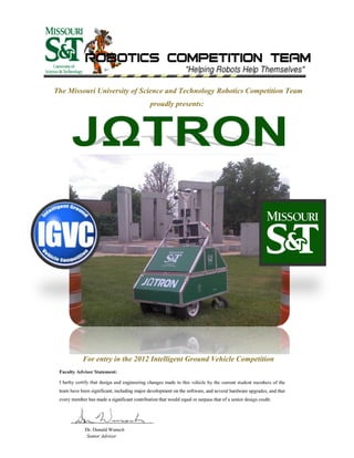
The Missouri S&T Robotics Competition Team presents their entry, Jomegatron, for the 2012 Intelligent Ground Vehicle Competition. Jomegatron has undergone significant upgrades in its mechanical, electrical, and software systems based on lessons learned from previous competitions. The mechanical upgrades include a new caster drive system and adjustable camera mount. The electrical system was completely redesigned and now uses more robust components. The software was expanded to include new mapping and JAUS capabilities while improving existing vision and navigation functions. Testing showed the upgrades improved reliability, mobility, and intelligence to allow Jomegatron to better handle complex obstacle courses.
This document outlines the program educational objectives, curriculum development process, career paths, program outcomes, technical skills, and subjects for an Automobile Engineering program. The objectives are to meet industry and research needs, encourage higher education, and promote entrepreneurship. The curriculum aims to develop sound technical and professional skills. Career paths include manufacturing, design, research, and government roles. Program outcomes include skills in problem solving, design, safety, and lifelong learning. Technical skills and correlating subjects are listed to enhance abilities in areas like repair, drafting, analytics, and alternative fuels. Suggested curriculum modifications are provided.
Edmund S. Browalski has over 40 years of experience in the automotive industry, specializing in vehicle dynamics and electronic control systems. He has held leadership roles at General Motors developing technologies like traction control, electronic stability control, and integrated chassis systems. Currently, he runs his own consulting firm providing expertise in areas like product evaluation, technical specifications, and analytical reports. His background includes extensive experience in advanced development, production implementation, and mentoring younger engineers.
Kumar Mritunjay is seeking a career opportunity in core engineering that requires technical skills and strong analytical abilities. He has a Bachelor's degree in Mechanical Engineering and over 3 years of experience in automotive engineering at Mahindra & Mahindra. As Deputy Manager of Plant Engineering, he is responsible for new engine project development, facility planning, and process improvement. His skills include project management, budgeting, facility planning, and implementation of quality systems.
Robert Palma is a mechanical engineering student at the University of Central Florida expected to graduate in December 2016. He has worked as a Structures Engineer at Blue Origin LLC where he designed and tested carbon fiber panels. He has also served in multiple leadership roles for UCF's Society of Automotive Engineers club, managing budgets, leading vehicle design teams, and mentoring over 40 students. His experience includes structural analysis, manufacturing, and hands-on fabrication skills.
IRJET- Determination of Critical Downforce Coefficient of a Vehicle for Optim...IRJET Journal
This document describes a study to determine the critical downforce coefficient of a vehicle for optimal aerodynamic performance. The researchers used a Formula SAE race car and the Buddh International Circuit track for simulations. They simulated increasing levels of downforce coefficient and measured the effect on lap times. They found that downforce initially improved lap times by increasing cornering ability. However, beyond a critical point, the increased drag from higher downforce began to outweigh the benefits, slowing lap times. The goal was to determine this critical downforce coefficient value through analytical calculations and simulations using OptimumLap software.
Autonomous Terrain Mapping Using COTS HardwareJames Anderson
Undergraduate paper submission for 2012 International Telemetering Conference
Abstract: The paper describes the development of a robotic platform which can autonomously map terrain using a COTS infrared imaging and ranging system. The robotic system is based on an omni-directional platform, and can navigate typical commercial indoor environments. An on-board processor performs surface reconstruction, and condenses the point clouds generated by the ranging system to mesh models which can be more easily stored and transmitted. The processor then correlates new frames with the existing world model by using sensor odomerty. The robot will autonomously determine the best areas of the environment to map, and gather complete three dimensional color models of arbitrary environments.
Toyota Overview
Toyota; Implementation of a New Business Process
Toyota; an Overview
Toyota is a Japanese auto-manufacturer that is famed for the production of high quality products that are relatively cheap. With pricing strategies that resonate throughout the social classes (i.e. the rich, the middle class and the poor), the car-maker has a vast global market share that helps place it at the top of the motor vehicle industry.
The Purpose of Toyota’s Existence
With regard to what Toyota Global stands for, Toyota as a company looks to redefine its business strategy by producing high quality automobiles, gain market competitive edge and to increase its technologies to align in the production of eco-friendly vehicles (Alukal, 2007). In addition to that, the corporation also emphasizes on the need for being socially responsible and to make an improvement on the lives of people all over the world; a promotion of the corporate citizenship agenda within its company.
Why Toyota is of Interest to Me
I am a lover of cars and recently I got to learn about LEAN and Six Sigma approaches and how they have helped a number of firms to up their game with regard to manufacturing, quality improvement and increasing market shares. Overall, Toyota is of interest to me because I have always thought it to be a competent manufacturer of vehicles (I personally own a Toyota Tundra truck); having to manufacture high quality vehicles and custom make them to suit different terrains for different end users is really commendable. Moreover, I would like to know how a process such as LEAN Six Sigma (Kaizen in Japanese) would be of use in a company like Toyota (Arnheiter & Maleyeff 2005).
A description of the project and its relationship to the organization’s business
Objectives
At the present, the executive management of Toyota has been looking to find ways to maximize the company’s production and total factor productivity while minimizing the cost of production (Kato & Smalley, 2010). This is in line with the corporation’s bigger scheme to increase the margins, maximize profit and beat competition with newly gained competitive advantages. The implementation of a new business process in Toyota’s production plants is basically the implementation of LEAN Kaizen (Al Smadi, 2009). Kaizen refers to a Japanese business principle that is bent on continuous improvement of the production process; employee working practices and personal efficiency on the part of executive management and operations assistants; all this is done in a bid to realize total factor productivity (labor, capital and technology). The Kaizen (business process) implementation project would help the company realize overall continuous improvement; a concept that is not only useful at the plant level where only manufacturing takes place, but also in other areas such as employee responsiveness and time management (Dahlgaard & Mi Dahlgaard-Park, 2006).
Availability of Organizational ...
I did Masters in Mechanical Engineering from Lamar University with 3.5 GPA. I have interest in manufacturing and design subjects. I have highest grade in all that subjects. I have 1 year of experience with teaching field at Lamar University. I was teaching CAD subjects to graduate and undergraduate student. I have professional 2 years of experience as a Design/Manufacturing Engineer. During that time I relocated machines using lean manufacturing concept to get maximum output. Moreover implement six sigma DMAIC concept to reduce lead time. I have very good knowledge of machining of metal components on CNC machines and laser cutting of sheet metal plate.I can work fluently on CAD software such as CREO, Pro-E, Solidworks, Unigraphics and Nastran.
This document proposes developing a vehicle management system for Amhara Region Science Technology and Information Communication Commission. It outlines analyzing the existing system, designing a new system using UML diagrams, and implementing the new system using Java Server Faces, PrimeFaces, MySQL, and IoT devices. The new system aims to modernize vehicle management processes, reduce errors, and provide efficient reporting and services for employees. It will manage user and vehicle data, local and trip requests, fuel consumption, and vehicle maintenance information. The proposal describes the project timeline which runs from November 2012 to June 2012.
Neural Net: Machine Learning Web ApplicationIRJET Journal
The document describes a machine learning web application called Neural Net that implements various machine learning algorithms. It includes two live projects - a COVID predictor and used car price predictor. The COVID predictor takes user symptoms and predicts the probability of infection using logistic regression. The car price predictor takes vehicle details and predicts the selling price using linear regression. The web application was created using HTML, CSS, JavaScript for the front-end and Python Flask for the back-end integration of machine learning models. The models were trained on various datasets to provide predictions with minimal error.
Running head: MANAGEMENT STRATEGY 1
MANAGEMENT STRATEGY 8
Management Strategy
James Smith
MBA6022 Unit 4 Assignment 1
2/7/16
ABSTRACT
We know the fact that quality and safety can be called as an important factor for every organization. This happen to Toyota when they were faced with an accelerator crisis after faulty accelerator pedals in some of their vehicles caused the pedals to depress get stuck or cause them to accelerate. This lead to a massive recall and lead to penalties and fines from the US government and consumer confidence diminished. In this presented assignment I will create a cause-and-effect diagram, create a graphic flowchart, create a before-and-after flowchart, I will describe the scope of my process improvement objective, and a revision of my problem statement based on what I learned about my objective by using the diagram and flowchart tools.
Cause-and-Effect Diagram
(
Resistance to
change
) (
Over-production
) (
Inventory
) (
Competitio
n
) (
Waiting /Delay
) (
Errors
) (
Faulty Accelerator
Car
, Death, and a Massive
Recall (Quality
issue
and safety issue
)
) (
Skills
) (
Motion
) (
Machine
) (
Process
) (
Manpower
) (
Environment
)
Information from the fishbone diagram does not seem to point to a certain cause or particular step in the flowchart but it does offer up more ideas to pinpoint the root cause of the problem by looking at the cause and effect relationships and lets you see where any bottlenecks in the process occur. It saves you from solving the problem and not finding out until later that it was only part of the problem. This saves time and resources by getting to the root cause of the problem because you can come up with solutions that enables you to look through the complexities of the problem. The fishbone diagram is literally like the bones of a fish. The head is where the larger issues are and as you go through the fish ending at the tail is the issue that do not have as much of an impact reside.
The fishbone diagram does not conflict with the initial flowchart but it does offer up more solutions then the original flowchart. While coming up with a problem statement, it was about focusing on one area that may have been causing the problem. According to Russell and Taylor (2014), the fishbone diagram allows us to look strategically at a wide range of areas that may be causing the problem.
While analyzing the cause and effect diagram we can able to understand that the quality and the safety of product is not up to the mark. And the process is affected by the different factors such as, unskilled labors and delay in providing quality services. The automobile market changing time to time and the interest of customers is also changing, so in order for gaining the profit the companies has to give more importance to the concept of quality (Imai 2012). In this case we can able to understand that, the company overestimated the demand for the.
This document discusses the development of a mobile application called PCE Connect for students at Priyadarshini College of Engineering (PCE). PCE Connect aims to be a companion app for students that contains several useful modules. It also aims to support emerging developers at PCE by providing them with a user-friendly interface and environment to develop applications. The app features an attractive interface and is designed to be intuitive and seamless for users. It includes modules like the college website, question papers, notes, aptitude tests, and more. Developing the app provides students access to important information and resources in one place through their mobile devices.
This document describes a web application called the Course Outcome Attainment Estimation System. The system allows faculty to accurately calculate course outcome attainment percentages and reduces the time required compared to manual calculations. Student continuous assessment marks, assignment marks, and other data are entered and stored in a database. The system then calculates individual course outcome percentages and graphs. It generates the overall course outcome attainment percentage using direct internal and external assessment marks. The objectives are to create an easy-to-use system that accurately calculates results with less time than manual methods. It also allows storing and printing results for future use.
IRJET- Design and Analysis of Suspension System, Brakes and Wheel Assembl...IRJET Journal
This document describes the design and analysis of the suspension system, brakes, and wheel assembly for an all-terrain vehicle (ATV). Key aspects of the design included improving vehicle handling, increasing ride height and wheel travel, and improving component durability. Suspension and brake systems were analyzed using Solidworks and Lotus simulation software. Design objectives such as performance, safety, manufacturability, and cost were prioritized. The suspension utilized double wishbone design with parameters like camber and castor optimized. Brake calculations were performed to select the master cylinder and calipers. The wheel assembly was designed to reduce unsprung mass while maintaining performance.
This document is a summer training report submitted by Abhikant Yadav from their time working at Sekisui DLJM Molding Pvt. Ltd. It provides an overview of Sekisui DLJM and its parent company Sekisui Chemical. Sekisui DLJM is an Indian joint venture between Sekisui Chemical and Dipty Lal Judge Mal Pvt. Ltd focused on plastic injection molding for automotive parts. The report details Sekisui Chemical's history and principles, the vision and quality policy of Sekisui DLJM, and Abhikant Yadav's experiences during their summer training.
1) Jeco Plastic Products, a custom plastic molder, faced losing a major multi-million dollar contract from a German automotive OEM due to a last-minute design change request that required rapid analysis.
2) Through the NDEMC program, Jeco gained access to modeling, simulation, and analysis (MS&A) expertise and resources at Purdue University, including the SIMULIA Abaqus FEA software and Ohio Supercomputer Center, to analyze the design change.
3) With NDEMC's support, Jeco was able to simulate and analyze the design change in a timely manner, securing the contract. This success has led to projected doubled annual revenues for Jeco
Design and Fabrication of Human Powered CycleIRJET Journal
This document describes the design and fabrication of a human powered cycle. It aims to create a more efficient bicycle that requires less human effort. The design uses a treadle mechanism instead of a traditional chain and sprocket system to transmit more power from the pedals to the wheels. The parts were designed using Fusion 360 software and fabricated. The human powered cycle is a tricycle that uses a stair climbing motion to power the vehicle. It aims to promote sustainable transportation that is lightweight and provides exercise.
This project report discusses the Matrix Core Builder machine used at Delphi Automotive Systems to produce condensers. The Matrix Core Builder is a fully automatic machine that works with the Central Machine to build condenser cores. It is used specifically to produce the condenser for the YE3 vehicle (codename) for Maruti Suzuki. The report provides an overview of the various production departments at Delphi and describes the process the Matrix Core Builder uses to manufacture the YE3 condenser through various automatic steps before testing and quality checks.
This case study examines quality improvement efforts at Caparo Maruti Ltd through the application of Six Sigma methodology. The company manufactures sheet metal automobile parts, including cross members. Data was collected on inspections of 187525 cross member parts over 5 months, finding 67 defects. Major defects included welding failures causing nut misplacement or damage. Pareto and line charts identified the primary defect as M8 nut failure during projection welding. Root cause analysis using a fishbone diagram indicated issues with the welding process, including variation in weld gun position, nut placement, and material quality. Recommendations were made to improve the welding process and reduce defects.
Microsoft India - Total Economic Impact of Microsoft SQL Server 2008 Upgrade ...Microsoft Private Cloud
Conducting in-depth interviews with an existing SQL customer that upgraded to SQL Server 2008, Forrester found that the organization achieved benefits, some easily measured for this ROI study and others, equally as valuable, that could not be quantified. Specifically, the benefits fall into the following categories: 1) avoided adding SQL Server 2008 servers – license and hardware savings; 2) avoided adding storage; 3) eliminated third-party software; 4) avoided hiring additional IT employees; 5) increased user productivity – business and IT; 6) improved database performance
and provided enhanced features; 7) improved data security; and 8) improved working experience for the database administration team. Only the first five benefits were quantified as part of the ROI
analysis. To fully understand the potential effect on their organizations, readers should consider all benefits, whether or not they could be quantified for this study.
IRJET- Placement Portal and Prediction SystemIRJET Journal
1. The document proposes a student portal and prediction system that uses logistic regression to predict a student's probability of success during the placement process and getting placed at different companies.
2. The system was developed using a dataset collected from a survey of engineering college students regarding their skills and performance. Logistic regression was selected as the predictive model due to its efficiency and accuracy.
3. The system works by storing user test results in a database. The results are classified into features like quant scores and verbal scores which, along with CGPA, serve as inputs for the logistic regression model to determine a student's likelihood of placement at a company.
This document provides a summary of the industrial training completed by Ajay Kumar at Lumax Mannoh Allied Technologies from June 15th to July 15th, 2016. It includes an introduction to APQP (Advanced Product Quality Planning), the major elements and phases of APQP, examples of process outputs like an FFMEA (Failure Mode and Effects Analysis). It also summarizes key failure modes, effects, potential causes and controls as part of the FFMEA process for improving product quality.
IRJET - Higher Education Access Prediction using Data MiningIRJET Journal
This document describes a system for predicting student access to higher education using data mining. The system allows students to take online entrance exams and immediately receives their results and a list of recommended colleges based on their scores. It uses an artificial intelligence to automatically grade exams and allocate marks. The system has modules for student registration, exam taking, result viewing, and feedback. It aims to provide a quick and easy exam process and reduce human errors in grading.
This document provides an overview of an internship program at ELGI Company in Coimbatore, India. It includes acknowledgements, background on the company, objectives of the internship, and problem statement. The problem statement is to study transmission error in gears, predict transmission error for a given gear pair, and analyze the influence of various factors. The document contains sections on transmission and gears, sources of noise in gear systems, definitions of terms related to transmission error, algorithms for evaluating transmission error, description of an actual gear system to analyze, and a case study analyzing different variables.
The team developed a new competency model combining aspects of the merged companies and built an annual review into the UltiPro Performance Management system, piloting it with 10% of employees. They received positive feedback on the system's ease of use. Next steps include finalizing the competency framework, piloting the engagement review, surveying employees on review formats, and revising the annual review process in the system.
Application of Lean Construction Techniques in Civil Engineering: Plucking th...IRJET Journal
This document discusses the application of lean construction techniques in civil engineering projects to reduce waste. It defines lean construction as eliminating waste from the construction process to reduce time and costs. The document outlines various lean tools that can be used, such as computer-aided design, visual inspection, continuous improvement programs, and value stream mapping. It also discusses the benefits of lean construction, such as increased productivity, quality improvement, reduced construction time, and improved access to information. The conclusion states that lean principles were developed in the automotive industry and are now being applied more in construction to improve efficiency.
DEVELOPMENT OF A WHEEL HUB BY TOPOLOGICAL OPTIMIZATION METHOD APPLIED TO A SA...IRJET Journal
The document describes the development of a rear wheel hub for a Formula SAE vehicle using topological optimization and finite element analysis. An initial wheel hub geometry was modeled based on benchmark data. Loads from acceleration, braking, cornering and weight transfer were calculated. Topological optimization was then used to reduce the mass of the initial design by 37% while maintaining structural integrity. A finite element analysis found the optimized design had sufficient strength and an infinite fatigue life.
More Related Content
Similar to Missouri University of Science & Technology 2012
This document proposes developing a vehicle management system for Amhara Region Science Technology and Information Communication Commission. It outlines analyzing the existing system, designing a new system using UML diagrams, and implementing the new system using Java Server Faces, PrimeFaces, MySQL, and IoT devices. The new system aims to modernize vehicle management processes, reduce errors, and provide efficient reporting and services for employees. It will manage user and vehicle data, local and trip requests, fuel consumption, and vehicle maintenance information. The proposal describes the project timeline which runs from November 2012 to June 2012.
Neural Net: Machine Learning Web ApplicationIRJET Journal
The document describes a machine learning web application called Neural Net that implements various machine learning algorithms. It includes two live projects - a COVID predictor and used car price predictor. The COVID predictor takes user symptoms and predicts the probability of infection using logistic regression. The car price predictor takes vehicle details and predicts the selling price using linear regression. The web application was created using HTML, CSS, JavaScript for the front-end and Python Flask for the back-end integration of machine learning models. The models were trained on various datasets to provide predictions with minimal error.
Running head: MANAGEMENT STRATEGY 1
MANAGEMENT STRATEGY 8
Management Strategy
James Smith
MBA6022 Unit 4 Assignment 1
2/7/16
ABSTRACT
We know the fact that quality and safety can be called as an important factor for every organization. This happen to Toyota when they were faced with an accelerator crisis after faulty accelerator pedals in some of their vehicles caused the pedals to depress get stuck or cause them to accelerate. This lead to a massive recall and lead to penalties and fines from the US government and consumer confidence diminished. In this presented assignment I will create a cause-and-effect diagram, create a graphic flowchart, create a before-and-after flowchart, I will describe the scope of my process improvement objective, and a revision of my problem statement based on what I learned about my objective by using the diagram and flowchart tools.
Cause-and-Effect Diagram
(
Resistance to
change
) (
Over-production
) (
Inventory
) (
Competitio
n
) (
Waiting /Delay
) (
Errors
) (
Faulty Accelerator
Car
, Death, and a Massive
Recall (Quality
issue
and safety issue
)
) (
Skills
) (
Motion
) (
Machine
) (
Process
) (
Manpower
) (
Environment
)
Information from the fishbone diagram does not seem to point to a certain cause or particular step in the flowchart but it does offer up more ideas to pinpoint the root cause of the problem by looking at the cause and effect relationships and lets you see where any bottlenecks in the process occur. It saves you from solving the problem and not finding out until later that it was only part of the problem. This saves time and resources by getting to the root cause of the problem because you can come up with solutions that enables you to look through the complexities of the problem. The fishbone diagram is literally like the bones of a fish. The head is where the larger issues are and as you go through the fish ending at the tail is the issue that do not have as much of an impact reside.
The fishbone diagram does not conflict with the initial flowchart but it does offer up more solutions then the original flowchart. While coming up with a problem statement, it was about focusing on one area that may have been causing the problem. According to Russell and Taylor (2014), the fishbone diagram allows us to look strategically at a wide range of areas that may be causing the problem.
While analyzing the cause and effect diagram we can able to understand that the quality and the safety of product is not up to the mark. And the process is affected by the different factors such as, unskilled labors and delay in providing quality services. The automobile market changing time to time and the interest of customers is also changing, so in order for gaining the profit the companies has to give more importance to the concept of quality (Imai 2012). In this case we can able to understand that, the company overestimated the demand for the.
This document discusses the development of a mobile application called PCE Connect for students at Priyadarshini College of Engineering (PCE). PCE Connect aims to be a companion app for students that contains several useful modules. It also aims to support emerging developers at PCE by providing them with a user-friendly interface and environment to develop applications. The app features an attractive interface and is designed to be intuitive and seamless for users. It includes modules like the college website, question papers, notes, aptitude tests, and more. Developing the app provides students access to important information and resources in one place through their mobile devices.
This document describes a web application called the Course Outcome Attainment Estimation System. The system allows faculty to accurately calculate course outcome attainment percentages and reduces the time required compared to manual calculations. Student continuous assessment marks, assignment marks, and other data are entered and stored in a database. The system then calculates individual course outcome percentages and graphs. It generates the overall course outcome attainment percentage using direct internal and external assessment marks. The objectives are to create an easy-to-use system that accurately calculates results with less time than manual methods. It also allows storing and printing results for future use.
IRJET- Design and Analysis of Suspension System, Brakes and Wheel Assembl...IRJET Journal
This document describes the design and analysis of the suspension system, brakes, and wheel assembly for an all-terrain vehicle (ATV). Key aspects of the design included improving vehicle handling, increasing ride height and wheel travel, and improving component durability. Suspension and brake systems were analyzed using Solidworks and Lotus simulation software. Design objectives such as performance, safety, manufacturability, and cost were prioritized. The suspension utilized double wishbone design with parameters like camber and castor optimized. Brake calculations were performed to select the master cylinder and calipers. The wheel assembly was designed to reduce unsprung mass while maintaining performance.
This document is a summer training report submitted by Abhikant Yadav from their time working at Sekisui DLJM Molding Pvt. Ltd. It provides an overview of Sekisui DLJM and its parent company Sekisui Chemical. Sekisui DLJM is an Indian joint venture between Sekisui Chemical and Dipty Lal Judge Mal Pvt. Ltd focused on plastic injection molding for automotive parts. The report details Sekisui Chemical's history and principles, the vision and quality policy of Sekisui DLJM, and Abhikant Yadav's experiences during their summer training.
1) Jeco Plastic Products, a custom plastic molder, faced losing a major multi-million dollar contract from a German automotive OEM due to a last-minute design change request that required rapid analysis.
2) Through the NDEMC program, Jeco gained access to modeling, simulation, and analysis (MS&A) expertise and resources at Purdue University, including the SIMULIA Abaqus FEA software and Ohio Supercomputer Center, to analyze the design change.
3) With NDEMC's support, Jeco was able to simulate and analyze the design change in a timely manner, securing the contract. This success has led to projected doubled annual revenues for Jeco
Design and Fabrication of Human Powered CycleIRJET Journal
This document describes the design and fabrication of a human powered cycle. It aims to create a more efficient bicycle that requires less human effort. The design uses a treadle mechanism instead of a traditional chain and sprocket system to transmit more power from the pedals to the wheels. The parts were designed using Fusion 360 software and fabricated. The human powered cycle is a tricycle that uses a stair climbing motion to power the vehicle. It aims to promote sustainable transportation that is lightweight and provides exercise.
This project report discusses the Matrix Core Builder machine used at Delphi Automotive Systems to produce condensers. The Matrix Core Builder is a fully automatic machine that works with the Central Machine to build condenser cores. It is used specifically to produce the condenser for the YE3 vehicle (codename) for Maruti Suzuki. The report provides an overview of the various production departments at Delphi and describes the process the Matrix Core Builder uses to manufacture the YE3 condenser through various automatic steps before testing and quality checks.
This case study examines quality improvement efforts at Caparo Maruti Ltd through the application of Six Sigma methodology. The company manufactures sheet metal automobile parts, including cross members. Data was collected on inspections of 187525 cross member parts over 5 months, finding 67 defects. Major defects included welding failures causing nut misplacement or damage. Pareto and line charts identified the primary defect as M8 nut failure during projection welding. Root cause analysis using a fishbone diagram indicated issues with the welding process, including variation in weld gun position, nut placement, and material quality. Recommendations were made to improve the welding process and reduce defects.
Microsoft India - Total Economic Impact of Microsoft SQL Server 2008 Upgrade ...Microsoft Private Cloud
Conducting in-depth interviews with an existing SQL customer that upgraded to SQL Server 2008, Forrester found that the organization achieved benefits, some easily measured for this ROI study and others, equally as valuable, that could not be quantified. Specifically, the benefits fall into the following categories: 1) avoided adding SQL Server 2008 servers – license and hardware savings; 2) avoided adding storage; 3) eliminated third-party software; 4) avoided hiring additional IT employees; 5) increased user productivity – business and IT; 6) improved database performance
and provided enhanced features; 7) improved data security; and 8) improved working experience for the database administration team. Only the first five benefits were quantified as part of the ROI
analysis. To fully understand the potential effect on their organizations, readers should consider all benefits, whether or not they could be quantified for this study.
IRJET- Placement Portal and Prediction SystemIRJET Journal
1. The document proposes a student portal and prediction system that uses logistic regression to predict a student's probability of success during the placement process and getting placed at different companies.
2. The system was developed using a dataset collected from a survey of engineering college students regarding their skills and performance. Logistic regression was selected as the predictive model due to its efficiency and accuracy.
3. The system works by storing user test results in a database. The results are classified into features like quant scores and verbal scores which, along with CGPA, serve as inputs for the logistic regression model to determine a student's likelihood of placement at a company.
This document provides a summary of the industrial training completed by Ajay Kumar at Lumax Mannoh Allied Technologies from June 15th to July 15th, 2016. It includes an introduction to APQP (Advanced Product Quality Planning), the major elements and phases of APQP, examples of process outputs like an FFMEA (Failure Mode and Effects Analysis). It also summarizes key failure modes, effects, potential causes and controls as part of the FFMEA process for improving product quality.
IRJET - Higher Education Access Prediction using Data MiningIRJET Journal
This document describes a system for predicting student access to higher education using data mining. The system allows students to take online entrance exams and immediately receives their results and a list of recommended colleges based on their scores. It uses an artificial intelligence to automatically grade exams and allocate marks. The system has modules for student registration, exam taking, result viewing, and feedback. It aims to provide a quick and easy exam process and reduce human errors in grading.
This document provides an overview of an internship program at ELGI Company in Coimbatore, India. It includes acknowledgements, background on the company, objectives of the internship, and problem statement. The problem statement is to study transmission error in gears, predict transmission error for a given gear pair, and analyze the influence of various factors. The document contains sections on transmission and gears, sources of noise in gear systems, definitions of terms related to transmission error, algorithms for evaluating transmission error, description of an actual gear system to analyze, and a case study analyzing different variables.
The team developed a new competency model combining aspects of the merged companies and built an annual review into the UltiPro Performance Management system, piloting it with 10% of employees. They received positive feedback on the system's ease of use. Next steps include finalizing the competency framework, piloting the engagement review, surveying employees on review formats, and revising the annual review process in the system.
Application of Lean Construction Techniques in Civil Engineering: Plucking th...IRJET Journal
This document discusses the application of lean construction techniques in civil engineering projects to reduce waste. It defines lean construction as eliminating waste from the construction process to reduce time and costs. The document outlines various lean tools that can be used, such as computer-aided design, visual inspection, continuous improvement programs, and value stream mapping. It also discusses the benefits of lean construction, such as increased productivity, quality improvement, reduced construction time, and improved access to information. The conclusion states that lean principles were developed in the automotive industry and are now being applied more in construction to improve efficiency.
DEVELOPMENT OF A WHEEL HUB BY TOPOLOGICAL OPTIMIZATION METHOD APPLIED TO A SA...IRJET Journal
The document describes the development of a rear wheel hub for a Formula SAE vehicle using topological optimization and finite element analysis. An initial wheel hub geometry was modeled based on benchmark data. Loads from acceleration, braking, cornering and weight transfer were calculated. Topological optimization was then used to reduce the mass of the initial design by 37% while maintaining structural integrity. A finite element analysis found the optimized design had sufficient strength and an infinite fatigue life.
Similar to Missouri University of Science & Technology 2012 (20)
DEVELOPMENT OF A WHEEL HUB BY TOPOLOGICAL OPTIMIZATION METHOD APPLIED TO A SA...
Missouri University of Science & Technology 2012
1. The Missouri University of Science and Technology Robotics Competition Team
proudly presents:
For entry in the 2012 Intelligent Ground Vehicle Competition
2. P a g e | 1
0.0 Introduction .................................................................................................................................................2
1.0 Design Process.............................................................................................................................................2
1.1 Team Structure ..........................................................................................................................2
1.2 Planning.....................................................................................................................................2
1.3 Execution...................................................................................................................................3
2.0 Vehicle Highlights/Innovations ....................................................................................................................3
2.1 Mechanical Upgrades.................................................................................................................3
2.2 Electrical Upgrades ....................................................................................................................3
2.3 Software Upgrades ....................................................................................................................4
3.0 Mechanical Design.......................................................................................................................................4
3.1 Frame ........................................................................................................................................5
3.2 Drive Train .................................................................................................................................5
3.3 Camera Mount...........................................................................................................................5
4.0 Electrical Design..........................................................................................................................................6
4.1 Sensors ......................................................................................................................................6
4.2 Computing.................................................................................................................................6
4.3 Actuators ...................................................................................................................................7
4.4 Power ........................................................................................................................................7
5.0 Software Strategy.........................................................................................................................................7
5.1 Vision.........................................................................................................................................8
5.2 Position......................................................................................................................................9
5.2 Model ........................................................................................................................................9
5.3 Navigation .................................................................................................................................9
5.4 JAUS.........................................................................................................................................10
5.5 Control.....................................................................................................................................10
5.6 Hardware Interface..................................................................................................................10
6.0 System Integration Plan.............................................................................................................................. 11
7.0 Performance Expectations.......................................................................................................................... 11
7.1 Complex Obstacle Handling......................................................................................................12
8.0 Safety ........................................................................................................................................................ 12
9.0 Cost in Dollars/Hours................................................................................................................................. 13
Appendix A: Member List ............................................................................................................................... 14
Appendix B: 2012 Schedule............................................................................................................................. 15
3. P a g e | 2
The Missouri University of Science and Technology (Missouri S&T) Robotics Competition Team is proud
to present " JΩtron " as its entry in the 2012 Intelligent Ground Vehicle Competition (IGVC). Joe-mega-tron is
named after the Missouri S&T mascot Joe Miner. The robot will be making its second appearance at the IGVC as
the eighth consecutive entry from the Missouri S&T Robotics Competition Team. The team has designed
Jomegatron using lessons it has learned from the robots of previous years. The simple design of Jomegatron makes it
ideal for the challenges presented by the IGVC. Jomegatron’s design has been greatly improved since its
performance in last year’s competition. The robot has seen improvements in reliability, mobility, and intelligence.
Jomegatron has become a very dependable platform which should be able to navigate almost any course
encountered during the 2012 IGVC.
The team operates through the Missouri
S&T Student Design and Experiential Learning
Center (SDELC), which provides logistical support
to all ten of the school’s student-run design teams.
The team is comprised of roughly 20 members from
a variety of disciplines. A full member list may be
found in Appendix A. The team is run by five elected
undergraduate officers who in turn appoint three additional officers to serve year-long terms. The team president,
vice president, treasurer, public relations officer, and secretary comprise the five elected positions. At the beginning
of the school year, three division leaders are appointed, each of whom oversees and manages one of the team's three
divisions: mechanical, electrical, and computing. All of the other team members are a part of one or more of these
divisions. This team structure (Figure 1) allows the general members of the team to operate without being distracted
by the day-to-day logistics that come with running the team.
During the 2011 IGVC Jomegaton performed admirably and was able to successfully navigate large
sections of the course. The primary goal set forth by the team at the beginning of the 2011-12 school year was to
maintain and build on this success. To accomplish this goal the team looked for the rough spots in Jomegatron’s
performance and designed ways to improve performance. During the competition Jomegatron had several problems
with the reliability of its mechanical and electrical systems. The team decided to redesign the drive platform and
embedded circuits of the robot. Jomegatron’s software also had several problems during competition and lacked
some functionality. The team decided to implement several new methods in the software that could be used in
conjunction with old software. The new additions to Jomegaton were designed to add capabilities and overall
robustness to the platform without destroying any progress that was made the previous year. A full schedule was laid
Figure 1: Team Structure
4. P a g e | 3
out, including ample time for the design and implementation of changes as well as several testing dates to ensure the
desired operation. The original Schedule may be found in Appendix B.
During the 2011-12 school year the team was able to stick to its schedule fairly tightly. The mechanical
division was able to perform needed maintenance and implement various upgrades to Jomegatron. The robot’s
mobility and structure were greatly improved. The electrical division stayed on schedule and was able to improve
the charging and control circuits of the robot. The computing division was able to implement new mapping and Joint
Architecture for Unmanned Systems (JAUS) capability as well as improving the performance of previous software.
The team was also able to add several new software strategies to its code base that were not originally planned.
Several tests were performed throughout the year and improvements were seen in all areas. Overall, the team stayed
on track and made many improvements to Jomegatron. With the new designs applied to Jomegatron it is a much
better robot than it was last year and the team believes that it will make an impressive run in the 2012 IGVC.
By building on the lessons of previous years the team has created a robot fine-tuned to the needs of this
competition. The problems of the 2011 model have been resolved, new capabilities have been added and the overall
reliability of the platform has been increased. Underneath the Lexan shell of the 2012 model there have been major
innovations in both hardware and software that will give Jomegatron the edge in this year’s competition.
While most of the frame has remained the same there were
major renovations made to the drive train (Figure 2). Jomegatron
experienced some problems turning with the 4-wheel skid-steer
drivetrain of the previous year. To alleviate this, a caster system
was implemented. The front wheels remain independently
powered, while the back wheels were replaced with casters.
Casters were placed in the both rear corners of Jomegatron to
provide a high level of stability. A hinge was also added to the
camera mast on top of Jomegatron, allowing it to fold down for
transport. This allows the team to fit Jomegatron in the back of a
pickup truck for easy transportation.
This year Jomegatron was upgraded with a new Emergency Stop (E-stop) control board. During the board's
replacement, some upgrades were made. The new E-stop board is triple redundant, as was its predecessor. The
computer, remote control, and physical buttons on the platform can all be used to E-stop the robot. There is now a
switch on the E-stop board so that software control can by bypassed in the event that a board failure occurs. Even if
Figure 2: Caster System
5. P a g e | 4
software control is bypassed, the hardware buttons still function
properly. The E-stop board also serves as a power regulator, with the
ability to provide 24V for the E-stop switches and 5V for the onboard
micro-controller. The 5V supply can also be used to drive other small
boards that the team may want to add in the future.
The E-stop board has two methods of communication: serial
and USB. The E-stop board includes a USB to serial converter,
allowing the board to be plugged directly into the computer. The serial
port also allows the board to communicate to a remote E-stop switch.
The board is able to wirelessly send data back to the remote E-stop
with battery measurements or other information the team wishes to
display. With sixteen general purpose IO pins, the E-stop board can be easily upgraded to provide additional
functionality as the team deems it necessary.
The primary goals of the software team were
to add mapping and JAUS capabilities as well as
improving the vision and navigation software. The
operation of the previous year’s software has been left
entirely intact by adding additional modules to the
software stack. The team now has the capability to
choose from several different strategies for vision,
mapping, and navigation. All strategies may be chosen
at runtime, allowing the team to simultaneously develop
several different strategies and easily test them in the
field. In addition to new capability the software now
interfaces with the RViz display program to present map
and sensor data, and allow for the input of waypoints. The new software has made Jomegatron better able to handle
complex situations and gives users a much greater amount of feedback.
Jomegatron’s mechanical design was built around simplicity and flexibility. The robot frame was built to
be simple and allow easy access to internal components. The drive train gives the robot a zero point turn radius for
maximum mobility, and the robot’s profile allows it to fit through standard doorframes. The robot includes several
locations that provide flexible mounting solutions for various sensors. The overall mechanical design provides a
robust platform for all of the team’s development needs.
Figure 3: Custom E-Stop Board
Figure 4: RViz User Interface
6. P a g e | 5
Jomegatron’s frame is made out of 1 inch by 1 inch aluminium square tubing and is 28 inches wide by 40
inches long. The frame itself is divided into two sections, the upper half and the lower half. The upper half is
attached to the bottom using a hinge and two hydrolic springs,
much like you would see on the hood or trunk of a car. This
allows very easy access to the bottom portion of the robot,
making it easy to change batteries, pull equipment out, or put
new components in. The frame itself is welded together in order
to ensure its endurance through many years of use. Jomegatron’s
frame is also relatively large in order to ensure that there is
enough room for components. Extra room was designed to
allow for easy upgrades.
The shell of the robot is attached using small,
permanent magnets. The magnets attach to steel contact points on
the frame, allowing for easy attachment and removal. This method
ensures that there will always be an easy way to remove the shell
for access to internal components.
For Jomegatron’s drive train, the team utilized a differential steering configuration with two powered
wheels in the front and two caster wheels in the back. The gearboxes were custom designed and fabricated by the
team to fit motors that were donated by the team’s sponsor, Elmo. The two caster wheels are mounted on steel angle
iron for strength and placement purposes. The wheels are mounted just inward of the rear corners to provide
maximum stability, but do not extend far enough past the frame to interfere with obstacles. These components are
bolted on so the team can easily make adjustments or perform maintenance on the drive train.
The bolted-down camera mount, which sits rigidly on top of the robot,
is made of the same 1 inch by 1 inch aluminum square tubing that comprises the
frame. The mast reaches up to a height of 5 feet in order to give the robot’s
camera a bird’s-eye view. The camera mount consists of two parts: the upper
and lower half. The lower half holds the display, while the upper half holds the
wide angle camera. This upper part was designed to be very adjustable. There
are holes every inch on the mount to guarantee the ideal camera angle. The
upper mount holds the camera in two places and allows the camera’s downward
angle to change, but also keeps it locked in place while Jomegatron is moving.
The camera mount was designed to satisfy the needs of this year’s software and
to accomodate any changes that may be made in the future.
Figure 5: Camera Mount
Figure 4: Solidworks Frame Design
7. P a g e | 6
Jomegatron features a completely new electrical
system with improvements based on several previous years
of experience. This system is designed to serve the team for
years to come without any foreseeable need for service or
significant changes.
Jomegatron employs a single Point Grey Firefly MV
camera. This camera operates at a resolution of 0.3
megapixels and is able to supply VGA (640x480) images at
30FPS over a standard IEEE 1394a “Firewire” connection.
Standardization of 1394 cameras provides access to all
internal setting registers for camera configuration. A
removable lens with a 2.2mm focal length provides a 130-
degree field of view.
Jomegatron utilizes a Microbotics MIDG-II INS/GPS as its primary position / pose sensor. This device
includes a WAAS compliant GPS, a 3-axis accelerometer, a 3-axis rate gyro, and a 3-axis magnetometer. The device
is capable of integrating positional information through an on-board Kalman filter and sending revised position /
pose information via a serial interface at 50 hertz.
Additional positional information can be derived from the motor controllers, which maintain a running
position based on the wheel encoders. This derived positional information is relatively accurate at short time scales
but tends to drift over time due to wheel slippage. The combination of the GPS for long-term absolute accuracy,
accelerometers for intermediate accuracy, and wheel encoders for short-term accuracy is used to determine the most
probable position at any point in time.
Jomegatron carries a full desktop computer to handle all of the vision, mapping, and navigation tasks the
team requires for competition. The computer has an 2.2 GHz Intel quad core processor, and a GT 430 Nvidia
graphics card to aid in vision processing. The graphics card gives the team the ability to perform parallel processing
on images, providing a large speed increase. The computer uses a solid state drive to store data, allowing memory to
be safely accessed while the robot is in motion.
The computer runs Ubuntu Linux and may be controlled through the onboard wireless router or via the
monitor, keyboard, and mouse mounted to the robot. This allows the team to easily make and test changes to the
software. The robot automatically connects to external wireless networks, allowing software changes to be pushed to
Figure 6: Simplified Sysem Diagram
8. P a g e | 7
the team’s software repository. Debugging information can be displayed on the monitor, along with graphical
interfaces for changing code parameters. A second monitor mounted to the front of the robot is used to display
information to third parties during testing as well as public relations events.
Jomegatron uses two permanent magnet synchronous motors to drive the main wheels. The motors are
controlled using “Drum” motor controllers from Elmo Motion Control. Each motor is capable of supplying 900W of
power, which gives Jomegatron high maneuverability even on rough terrain. Permanent magnet machines are known
for their high torque output, meaning that Jomegatron won't stall under load. The motors are rated for 100 volts
each, as are the motor controllers. This leaves room to upgrade Jomegatron's power system in the future if the team
feels that such an upgrade is necessary.
Jomegatron has a custom power supply to run all of the computer components. The power supply runs
directly off the 48 volts supplied by the batteries with no converters necessary. It can power monitors, the computer,
the camera, speakers, and a router. The power supply is capable of supplying up to 500 watts, which leaves the team
a lot of room to add more computer components if necessary in the future.
Jomegatron’s software was programmed in C++ and designed around Robot
Operating System (ROS). ROS provides a dynamic and robust transport layer for the
robot. The system allows code modules to be linked at runtime, making it easy to edit
or replace a single module without the user being required to comprehend the program
as a whole.
A simplified overview of the current software architecture may
be found in Figure 7. The software stack is designed
to map the environment and navigate to GPS (Global
Positioning System) waypoints using the input from a
single monocular camera. The software provides a
Graphical User Interface (GUI) to display debugging
data and allows users to provide inputs via the GUI or a
Wiimote wireless controller.
The team uses Git revision control software to track
changes. All software is available under the Open Source
GPL v3 license. The software may be found in the team’s
GitHub repository at https://github.com/MST-
Robotics/Jomegatron_IGVC.
Figure 7: Software Architecture
9. P a g e | 8
The primary sensor of Jomegatron is a 640x480 resolution wide angle camera. The first step of the vision
pipeline is to identify obstacles. As described below, the team has developed two primary methods for finding
obstacles. Both methods attempt to identify obstacles based on their color and output an image marking all of the
obstacles within each frame.
The per-pixel based method of image segmentation identifies obstacles
based on their color characteristics. The user specifies the colors of various
obstacles in the frame as well as the color of the grass. The software creates
distribution curves based on the input colors’ chromaticity and brightness
components. When images are published from the camera driver every pixel in
the image is given a probability of being an obstacle based on where it lies on
the distribution curves. The module publishes a grayscale image defining each
pixel by the probability that it is an obstacle.
The gradient based method of image segmentation attempts to first
segment the image into regions of continuous color, then uses the statistics of
all the pixels in a region to determine obstacles. To do this the module creates
runs of pixels in the X and Y directions that have a consistent change in
gradient. The module looks at the second derivative of the image to determine
the start and stop of runs. The runs are then linked together into regions
defining areas with similar gradients. The statistics of all the pixels in these
regions are then compared to the statistics of the training obstacles to
determine obstacles within the image. The module publishes a binary image
defining the pixels that make up all obstacles within the image.
The modules may be launched separately or may be used together with
their outputs combined. The slalom flags of the competition are handled by
creating virtual walls to the right of the red flags and left of the green flags,
after segmentation is preformed. Once an image has been found with all of the
obstacles marked, a homography transform is performed on the image. The homography transform attempts to
create a bird’s eye view of the area around the robot, correlating obstacles on the ground plain to their positions in
the world. Ray-casting is then performed on the transformed image to give an array containing the distance to the
closest obstacle along each angle. Both the homography image and ray-cast are published. The various stages of the
image pipeline may be seen in Figure 8.
Figure 8: Image Pipeline
10. P a g e | 9
The position module is in charge of maintaining an accurate account of the robot’s position in the world.
The module subscribes to the position information being published by the GPS/INS unit and the wheel odometry.
The software combines all position information using a Kalman filter to maintain the most accurate position. The
module is also in charge of maintaining a list of GPS waypoints. The waypoints may be loaded from a file or may be
input by the user via the team’s GUI or using the JAUS protocol. The module decides the robot’s current target
based on priority. If two waypoints are given the same priority, such as those in no-man’s land, the program will
chose the closest. The user may set time limits on each priority to be sure the robot has enough time to finish the
course. Position outputs the combined position of the robot as well as the position of the robot’s next target.
The model module attempts to create an accurate
map of the world. The team’s current method uses the
gmapping stack, which may be found in the ROS repository.
The gmapping stack uses a Simulations Location and
Mapping (SLAM) algorithm to map the environment. The
module subscribes to the ray-cast output by the vision
pipeline and the combined position. The software places
local obstacle information into the global map by using the
combined position, and by tracking features from frame to
frame. The software uses the tracked features to create a
more accurate position and aid in future mapping. The
module outputs the corrected position as well as a local and
global map of obstacles. A map created of the team’s lab
using gmapping may be seen in Figure 9.
The navigation module is responsible for deciding the movement of the robot based on the obstacle map,
and the current target. As describes below, the team has two methods of determining the robot’s movement. The
methods output desired forward and rotational velocities for the platform.
Jomegatron’s software was designed to be compliant with the ROS navigation stack. The navigation stack
looks at the local obstacle map around the robot and determines the path needed to avoid close obstacles. The
software then looks at the global map and attempts to find a path that will lead to the next waypoint given by the
position node or by a user.
Figure 9: Map of the Team’s Lab
11. P a g e | 10
The potential navigation method was designed to mimic a gravity model with obstacles repelling the robot and
waypoints attracting it. The software uses the local model to sum all of the objects repelling the robot. Obstacles
that are closer to the robot repel it exponentially more than more distant obstacles. The software then gives the
robot a constant forward attraction and an attraction to the target waypoint. The module has a large number of
parameters that can be configured during operation, allowing the user to tune the performance.
The JAUS module was designed by the team to convert JAUS messages into ROS messages. The module
was designed to be as general as possible and can easily be used on other robots. The software supports all of the
JAUS capabilities and allows the user to pull information from the software and input controls.
The control node has the final control
over what velocity commands are sent to the
hardware interface module. The node has
several modes of operations that decide the
behavior of the robot. The module starts in
standby mode and waits for a Wiimote
controller to be connected or for the JAUS
node to take control. Once the user connects
he/she has the ability to place the robot into
either user controlled mode or autonomous
mode. In autonomous mode the node will pass
the velocity commands published by the
navigation software through to the motor
controller node, giving the software control over
the robot. In user controlled mode the software will interface with the Wiimote or JAUS module and compute
velocity commands based on user inputs.
The software also launches a ROS tool named RViz. RViz is a visualizer that allows the user to view
combined information about the robot’s inputs in a three-dimensional virtual environment. The output of the RViz
display may be seen in Figure 10. The display is customizable at runtime so users may view any debugging
information that is being published. Users are also able to subscribe to this data over a network, allowing for remote
operation. The node interfaces with a text-to-speech library to provide feedback about the current state of the robot.
The hardware interface node coverts the desired robot velocities output by control into wheel velocities.
The software uses the computed wheel velocities to create serial commands which are then sent to the motor
Figure 10: RViz Robot Dashboard
12. P a g e | 11
controllers. The module reads back the encoder information and publishes wheel odometry. The software also
interfaces with the E-stop board giving the state of the robot and control over the safety light.
Jomegatron’s control software was developed by several student members of the team all working on
different modules and levels. By using ROS the software was able to be developed in parallel. After the interfaces
were defined the internals of individual modules were coded by small teams.
Testing was performed at both the module level and at the system level.
Once acceptable behaviors were reliably demonstrated in the lab environment,
outdoor operational tests were conducted on a local field designed to replicate
the IGVC course.
Team members that participated in past IGVC events were able to re-
create all of the challenging features typically found at the IGVC, including
solid and dashed white painted lines, various densities of grass / dirt, shadows,
sun glare, slalom flags, cones of various types and colors, snow fencing, plank
saw-horses, switchbacks, center islands, dead ends, traps, potholes, and sand
pits.
During the spring semester, the team scheduled numerous outdoor tests,
each of which focused on a particular set of issues. After each test, the testing
sub-team reviewed the results, took notes, and made plans to address any
deficient performance observed.
The whole team feels very confident in Jomegatron’s ability to compete in the 2012 IGVC. The robustness
of its algorithms have been proven time and time again in simulations. The additions to the software have made the
robot much more reliable. The team’s predictions, along with the design’s demonstrated values, may be found
bellow in Table 1. The team has taken steps to ensure that spare parts for each of the robot’s components will be
available at the competition. The Missouri S&T Robotics Team expects Jomegatron to achieve the university's best
showing ever in the IGVC and to finish among the top five in the field.
Characteristic Design Goal Demonstrated in Field Test
Max Speed 5 MPH (2.237 M/s) 3.2 M/s (limited to 2.2 M/s in motor
controller firmware)
Reaction time - processing rate (sense-think-act loop) 4 hertz 7 hertz
Battery Life 1 hour 1.6 hours
Web Cameras : Web Cameras :
o 4 M forward o 4.5 M
o 3 M side – looking o 3.2 M
o 5 M Diagonal o 5.52 M
Accuracy of arrival at way points 2 M 1.5 M
Ramp Climbing Ability 15 degrees 22 degrees
Distance at which obstacles are detected
Figure 11: Field Testing
Table 1: Performance Comparison Table
13. P a g e | 12
The control software detects and handles the following special situations. Specific detection / handling methods
are described below:
When a switchback situation is encountered, Jomegatron will seek the path of least resistance. When no
such path is obvious the robot will drift along the closest edge until a clear path is found.
Jomegatron will tend to drive toward an area equidistant from all obstacles, be they lane lines or barrels.
This forces the robot to choose the widest path available, thus avoiding barrels in the center of a wide lane.
Jomegatron retains a global map of obstacles it has encountered on the field. If Jomegatron encounters a
dead end, it will return to the last fork it encountered and attempt a new path.
To negotiate traps, Jomegatron employs a method similar to that used to detect and navigate out of dead
ends.
Jomegatron will avoid all potholes provided they are a sufficiently different color than the grass.
Jomegatron’s navigation will tend to take the path of least resistance and the robot tends to want to move
forward. The spaces between the dashed lines of the course generally have a higher resistance than the correct path.
As a result the robot tends to veer away from dashed lines.
Slalom flags are detected as special obstacles by the vision software. Virtual walls are created to the right of
red flags and to the left of green flags. The walls prevent the robot from traversing the wrong side of flags. Once
the virtual walls are added the flags are treated as any other obstacle.
With all of the power Jomegatron can supply, there needs to be some way to stop the robot in case the
operator loses control. Jomegatron is equipped with a triple redundant E-stop. There are two buttons located at hand
height on the main frame of the robot. If either button is pressed, the motor controllers shut off, and relays switch the
motor power lines into a bank of resistors to bring the robot to a quick and easy stop. In addition to the buttons, an
AVR micro-controller takes commands from the computer and from a remote control to stop the robot remotely.
The computer must reset a count on the micro-controller every second to keep robot moving. If this watch-dog
14. P a g e | 13
requirement is not met, the robot will stop moving. This prevents the robot from running off in the event of a
computer glitch or total computer failure. There is also a remote control so that the robot may be stopped from afar
if necessary. In the event of a power failure the robot is automatically stopped.
By controlling Jomegatron with the Wii gaming console’s Wiimote controller, the team has a large amount
of control over the robot. The robot is also programmed to stop upon the loss of a Wiimote or Wireless E-Stop
connection or in the event of a crashed program. Jomegatron's hardware limits its speed to just less than five miles
per hour, and the fuses installed on the motors ensure that they receive no more than forty amps. If the Motors
module has not received a request in the last second, it will safely stop and turn off the motors. This prevents a
single module crash from causing a runaway situation.
Jomegatron has been in development for 2 years. The total accumulated financial cost of Jomegatron to the
team for those years comes to just above $7,700. A breakdown of costs may be found below in Table2.
Component Cost to Team Retail Value
Frame $500 $500
Motors $0 $1,300
Gear Boxes $300 $300
Shell $250 $250
Wheels $120 $120
Misc. Hardware $100 $100
Misc. Electrical $200 $200
Elmo Motor Controllers $4,000 $4,000
Batteries $260 $260
Charger $200 $200
Power Supply $300 $300
Point Grey Camera $700 $700
Computer $800 $800
Bluetooth Controler $0 $65
Microbotics INS/GPS $0 $5,710
Totals $7,730 $14,805
Table 2: Cost Analysis
Jomegatron’s construction and programming required a large amount of man hours. On the whole, the
team spent an average of 41 man hours per week preparing Jomegatron for this competition. Over the past two and
a half years of design and build, this amounts to a conservative estimate of 2,000 man hours. The team is very
proud of the robot it has created and expects to have a very successful run at competition.
15. P a g e | 14
Name Level Discipline
Anderson, James (Computing
Division Lead)-Appointed
Senior
Computer
Engineering
Anderson, Miriah (PR Officer)-
Elected
Senior
Mechanical
Engineering
Baleta, Joseph (Vice President)-
Elected
Sophomore
Mechanical
Engineering
Bertels, Jacob Sophomore
Computer
Engineering
Bessent, Chris Senior
Computer
Engineering
Boyko, Ken Graduate Computer Science
Chrisco, Michael Senior
Electrical
Engineering
Jason Gassel Sophomore Computer Science
Honse, Adam(Electrical Division
Lead)-Appointed
Senior
Computer
Engineering
Marik, Nick (Treasurer)-Elected Sophomore
Mechanical
Engineering
Painter, Chris (Team President)-
Elected
Junior
Mechanical
Engineering
Peterson, Daniel (Electrical Division
Lead)-Appointed
Junior
Electrical
Engineering
Reidmeyer, Andrew Sophomore
Computer
Engineering
Siebert, Christopher (Secretary)-
Elected
Sophomore Computer Science
Uhlman, David(Mechanical Division
Lead)-Appointed
Senior
Mechanical
Engineering
16. P a g e | 15
Week of
8/22
Week of
8/29 Week of 9/5 Week of 9/12
Week of
9/19
Week of
9/26
Week of
10/3 Week of 10/10
Week of
10/17
Week of
10/24
Week of
10/31
Week of
11/7
Week of
11/14
Week of
11/21
Thanksgiving
Key:
Computing
Mechanical
Electrical
General
2011 Proposal
Outdoor
test of
software
Position
Testingin
Field
Fix general Matience issuesdiscoveredonJΩtron
Design/buildmounts for newcomputer hardware
Data test
of
software
Refine Position
Get new members aquainted
withsoftware
Refine Model
Fabricate newE-StopBoard
DesignJΩtrone-stopboard
DesignJΩtronlowvoltage power supply
Week of 1/9
Week of
1/16
Week of
1/23
Week of
1/30
Week of
2/6
Week of
2/13
Week of
2/20
Week of
2/27 Week of 3/5
Week of
3/12
Week of
3/19
Week of
3/26
St.Pats Spring Break
Data testing of
state
software
Field
Testing
Field test of
state software
Repair StereoOptiocon
Refine Software
Fabricate LowVoltage Power supply
Build new cart for JΩtron
Design new JΩtron
charger
Build new charger
Week of 4/2 Week of 4/9
Week of
4/16
Week of
4/23
Week of
4/30 Week of 5/17 Week of 5/24 Week of 5/31 Week of 6/7
Finals Summer Break Summer Break Summer Break Summer Break
FieldTesting
Competition
Refine Software
Prepare JΩtronfor competition
Continue newcharger fabrication