This document describes a new tool called 3D Focal Mechanisms (3DFM) for visualizing earthquake focal mechanism symbols in three dimensions using ArcScene software. The tool takes as input a GIS point dataset containing location, focal plane orientation, and other data for earthquakes. It displays oriented spheres or "beach balls" at the earthquake locations to represent the focal mechanisms. Users can customize symbol appearance and filter the data. The tool is intended to help analyze spatial patterns in earthquake focal mechanisms.
Microsoft Producer for Microsoft Office PowerPoint 2003 Evaluation Guide@rte Digital
This document evaluates Microsoft Producer for Microsoft Office PowerPoint 2003, which allows users to easily create rich-media presentations using digital media and web files. It highlights key features such as importing files, capturing audio and video, adding effects, and publishing presentations. Guidelines are provided for using Producer to create cost-effective training, engaging business presentations, sales and marketing communications, and executive broadcasts.
NetApp system installation workbook SpokaneAccenture
This document provides site requirements for installing NetApp storage systems, including physical dimensions and weight specifications for various hardware components as well as power requirements. Environmental factors like clearance around systems is also addressed. Requirements for networking switches used with the systems are included.
Disk ownership
Launches the Disk Ownership Assistant
to assign ownership to unowned disks
3
*> disk assign
Manually assign ownership of unowned
disks
4
*> disk show -o
Display disk ownership information
5
*> disk remove
Remove ownership label from a disk
1.1.1.1 Modifying disk ownership
To modify disk ownership, use the disk assign and disk remove commands. For example:
*> disk assign -d 0b.83 -s 0
*> disk remove -d 0b.84
This assigns ownership of disk 0b.83 to the local storage system and removes ownership of
The document discusses the system requirements for installing and configuring Analysis Cubes for Microsoft Dynamics GP. It describes configurations where the Microsoft Dynamics GP and Analysis Cubes components are installed on the same server or on separate servers. It also covers requirements for client workstations and scenarios with multiple Analysis Cubes servers.
This document provides release notes for Oracle Developer Suite 10g Release 2 (10.1.2) for Solaris, Windows and Linux x86. It includes sections on certification information, known issues, and component release notes. The known issues section documents problems related to installation, configuration, documentation and other areas. The component release notes sections provide additional details on specific issues and limitations for Oracle Business Intelligence Beans, Oracle Forms, and other Developer Suite components.
This document provides an annual report on the state of information technology in Georgia state government for fiscal year 2014. It summarizes that the state invested $616 million in IT that year across executive branch agencies. It describes progress made in stabilizing, consolidating, and modernizing technology through initiatives like the Georgia Enterprise Technology Services program. It highlights how state agencies are aligning their technology goals to support the governor's strategic goals for the state. And it provides an overview of the state's efforts around areas like IT governance, security, financial management, and enabling technologies to support efficient and effective delivery of government services to citizens.
This document discusses using GRASS GIS to analyze land use and land cover changes in the Luswishi Farm Block in Zambia between 2001 and 2005 using Landsat 7 satellite imagery. It describes collecting the satellite images, preprocessing the images, and applying various digital image processing techniques like unsupervised classification, normalized difference vegetation index, principal component analysis, and tasseled cap transformation to detect changes. The goal is to map land use and detect temporal changes in the area to understand land use dynamics using open source GIS tools.
This chapter shows how to use the Data Wizard to add data to an existing HTML page template. The tutorial walks through opening the HTML template file, using the Data Wizard to connect to the sample schema and select the necessary data, and saving the file as a JSP. This creates a data model that makes the sample data available for use in generating the Web report.
This document discusses an individual's exclusive right to declare or establish their own civil status. It begins by noting that it is a state's duty to protect the civil status of its citizens and forbid interference by other states. It then provides definitions of civil status and discusses the main methods states use to control inhabitants by attaching obligations to property or civil statuses. Several legal authorities are cited that establish an individual's right to declare their own civil status, including international law, U.S. court cases, and constitutional provisions. The document concludes that individuals have remedies available if a government improperly changes or challenges their self-declared civil status.
This document provides a detailed policy analysis and rebuttal of the U.C.C. redemption approach. It introduces some of the main proponents of redemption theories and provides a high-level summary of the redemption approach. The bulk of the document systematically rebuts common redemption arguments, citing legal authorities. It concludes that redemption theories are factually and legally invalid and warns those associated with SEDM against using redemption processes or materials.
USGS Report on the Impact of Marcellus Shale Drilling on Forest Animal HabitatsMarcellus Drilling News
A report issued March 25, 2013 by the U.S. Geological Survey titled "Landscape Consequences of Natural Gas Extraction in Allegheny and Susquehanna Counties, Pennsylvania, 2004–2010." The report, using a series of maps and data, purports to show that drilling has lead to "carving up" wildlife habitats in some forests.
- Oracle Data Integrator is a tool for integrating data between heterogeneous systems and applications. It has components for modeling data, designing interfaces, executing integration processes, and monitoring results.
- The core components include repositories to store metadata, a design studio to create interfaces and mappings, and run-time agents that execute integration processes.
- This guide will help users get started with Oracle Data Integrator by walking through installing the software, exploring an example ETL project, and learning how to design and run integrations.
This document provides a 3-sentence summary of the given document:
The document is the user's guide and reference for PL/SQL Release 2 (9.2) from Oracle Corporation, covering the main features and functionality of PL/SQL such as blocks, variables, cursors, control structures, modularity, and error handling. It was last updated in March 2002 and has John Russell listed as the primary author along with several contributing authors. The document is copyrighted by Oracle Corporation and contains proprietary information regarding PL/SQL that is provided under a license agreement.
U.S. Government Protection Profile Web Server For Basic ...webhostingguy
This document provides a protection profile for web servers operating in basic robustness environments. It specifies requirements for commercial off-the-shelf web servers to provide security services like access control, identification and authentication, audit logging, and authorized administration. Web servers that meet the requirements specified in this protection profile are intended for environments with a relatively low security threat where data sensitivity is not very high.
This document provides an introduction to backup and recovery of Oracle databases, focusing on using Recovery Manager (RMAN) for common backup and recovery tasks. It discusses physical database structures used for recovering data like datafiles, redo logs, and control files. It also describes the database recovery process, different forms of data recovery, and how to match failures to appropriate backup and recovery techniques. Backup and recovery strategies are determined by the planned data recovery strategy.
This document provides an overview of new features and functionality in Microsoft Dynamics AX 2009. Some key updates include a refreshed user interface, new role centers, expanded workflow capabilities, and the Contoso demo data set. New financial management features include a fill utility, posting restrictions, reason codes, and enhancements to general ledger, accounts payable, accounts receivable, and fixed assets modules. Expense management functionality is now available through the Enterprise Portal. The supply chain management area also includes multisite updates.
This document is a user manual for the Well Plotter and Well Plotter 3D software. It provides instructions on installing the software, describes the user interface and functionality, and guides the user through adding wells and data, and visualizing data in 1D, 2D, and 3D views. The software allows users to import various types of geological, technical, and numerical borehole and well data and create visualizations to analyze the data.
This document describes new features and enhancements in Jedox Suite Release 3.3 SR2, including:
- Fixed issues from previous versions
- New sorting option in the OLAP Subset Editor
- Performance improvements and support for planning applications, enhanced reporting, usability, and mobile devices.
- Support for extremely large dimensions, multi-threaded reads, and GPU acceleration in Jedox OLAP.
- A task manager, scheduling PDF reports, and usability updates in Jedox Web.
- Selecting expanded branches and pasting values in Jedox for Excel.
- Component flow graphs, logging and scripting enhancements in Jedox ETL.
This document provides a 3 sentence summary of the key information from the given document:
The document is a handbook that provides instructions for using MeterBuddy2 software to program the Libra-3 electricity meter. It describes the various functions and settings that can be accessed through the MeterBuddy2 interface, including meter information, calibration settings, demand settings, time of use configuration, and event logging. The handbook provides step-by-step guidance for technicians to read data from and program parameters in the Libra-3 meter according to industry standards.
This document provides instructions for installing and setting up Key Performance Indicators (KPIs) in the Microsoft Dynamics GP Business Portal. It discusses how to create KPIs using queries, existing KPIs, or by copying existing KPIs. It also covers displaying KPIs, calculating values over multiple time periods, setting alert ranges, and configuring security roles and groups. The document contains steps for installation, creating and customizing KPIs, and displaying them in the Business Portal for users.
Archaeological Report - IDA Arklow Business & Technology Park, Ballynattin, C...John Tierney
The site was excavated under licence no. 04E0712. It was divided into ten areas of excavation: Areas 1-6, Area 6W, Area 7, Area 10 and Area 12.The earliest evidence for human activity was an Early Neolithic radiocarbon date obtained from the fill of a ditch in Area 6. However, there is no evidence for associated Early Neolithic activity. Most of the archaeological features excavated at Ballynattin were Bronze Age. Bronze Age pits were found in Area 6W, there was a spread of Bronze Age material in Area 3 and three partial Bronze Age structures were found in Areas 6 and 7. These were truncated and approximately only one third of each structure survived for excavation. A furnace excavated in Area 2 may also be Bronze Age in date; it has no associated radiocarbon dates but a saddle quern and flints were found within the furnace fill. The remaining features excavated at the site were primarily post-medieval, including a hearth excavated in Area 4, drains and ditches (Areas 1, 4 and 5) and a 19th century cobbled surface (Area 5).
This document discusses how individuals can defend themselves against demands from the government by asserting their right to be left alone and requiring the government to prove any claims or obligations. It argues that the only ways the government can create obligations are through common law violations that injure others or through contractual agreements. To win in court against the government, an individual must force the government to produce either an injured party or a valid contract showing the individual agreed to obligations. The document provides principles and examples for how to extract oneself from legal entanglements by requiring the government to meet its burden of proof in establishing obligations or claims against an individual.
Tech and media firms join Twitter in key test of FBI gag ordersMohamed Mahdy
This brief argues that Twitter should be allowed to publish transparency reports containing aggregate data about national security requests it receives. It contends that such data is protected speech on a matter of public concern, and that the nondisclosure rules associated with national security requests must survive strict scrutiny to restrict that speech. Specifically, the rules are a prior restraint and content-based restriction that are not narrowly tailored to serve a compelling government interest when they prohibit disclosure of aggregate numbers of requests.
This document provides an overview of the Perl Reference Manual for CDF (Coordinate Data Frame). It discusses compiling Perl scripts that interface with CDF, the programming interface including item referencing, passing arguments, status constants, CDF formats, data types, encodings, and more. The standard and internal interfaces for CDF functions in Perl are also described.
DB2 is a relational database management system that runs on IBM mainframes. It uses SQL for data manipulation and definition. A COBOL program can use DB2 services by including host variables, a SQL communication area, and SQL statements. DB2 has major components including system services, locking services, database services, and distributed data facility. The database services component handles tasks like precompiling, binding, running SQL statements, data management, and buffer management.
Frame analysis by autodesk inventor 2012HaGun Gunawan
This document contains 102 figures describing the process of creating and analyzing a frame using Autodesk Inventor Professional 2012. The figures show how to create the frame geometry, insert the frame profile, edit the frame, create constraints, run a simulation analysis, and generate a report of the results. The document appears to serve as a tutorial or instruction manual for using Autodesk Inventor to model and analyze a frame structure.
This document summarizes the applied software engineering assignment for developing a Monopoly game. It includes reverse engineering the original game and analyzing requirements. System requirements and use cases are defined. Class diagrams and state diagrams are created to model the game elements and their relationships. The re-engineering process uses test-driven development, with unit tests created for key components. Some tests are incomplete, demonstrating a need to fully implement testing. The document concludes with a review of test-driven development effectiveness and recommendations to improve the software quality.
Stress analysis 3 d auto cad by autodesk inventorHaGun Gunawan
This document provides instructions for performing a stress analysis on a 3D solid object created in AutoCAD and imported into Autodesk Inventor. It describes the steps to export the AutoCAD file, open it in Inventor, assign materials and constraints, apply loads, simulate stress analysis, and generate a report. The document includes 40 labeled figures illustrating each step of the process.
The document discusses the importance of financial planning for homemakers. It highlights three key points:
1. Financial planning is essential for everyone as it helps people meet life goals like buying a home, saving for children's education, and planning for retirement through proper management of finances.
2. It is important for homemakers to understand household finances so they are prepared in case the primary income earner can no longer manage the budget. This involves creating a budget, understanding expenses, and making sure the homemaker has access to financial accounts and documents.
3. The power of compounding interest is an important concept for long-term wealth creation. Even small regular investments can grow substantially over time due to compounding
El documento resume los principales puntos de un informe sobre la seguridad de los sistemas informáticos. Señala que los sistemas actuales son vulnerables a ataques cibernéticos y que es necesario mejorar la seguridad mediante el cifrado, la autenticación multifactor y la segmentación de redes. También recomienda capacitar al personal sobre ciberseguridad y realizar auditorías periódicas.
The JANTA program is an interactive platform that aims to digitize interactions between citizens and the government in India. It allows citizens to raise issues and problems to officials via a mobile app or website. It also aims to create a digital database of citizens' identities and assets. This includes digital addresses, driving licenses, and vehicle records linked to addresses and owners. It will give citizens a way to report issues like crimes, accidents or problems with public utilities to the relevant authorities. The government can then use the data and dashboard to identify problem areas and respond to citizens' needs. An initial pilot project is being launched in Ernakulam, Kerala.
The document appears to be an email with an attachment of a photo from pictures.com but provides no other context or information in the content. It is an email with a photo attachment from an online photo sharing website but without any accompanying message or details.
This document compares three cities in Texas - Dallas, Austin, and San Antonio. It summarizes some of the key attractions and culture of each city, including museums, parks, festivals, and theme parks. It also lists the average salaries for secondary teachers and physical therapist assistants in each city, with Dallas generally having the highest salaries and San Antonio generally having the lowest.
This document contains an address - 6573 Yadkin Ct, Alexandria, VA 22310 - repeated five times. It also contains the word "Springfield!" with no other context provided.
This document is a quotation from Shenzhen Core LED Limited providing pricing and specifications for various spotlights and downlights. It includes economic type spotlights with MR16 and GU10 bases in single color temperatures starting at $2.80 per unit. It also includes high quality types with MR16 bases in various wattages and chip types ranging from $2.85 to $9.69 per unit. E27 based downlights are also included with pricing from $3.30 to $5.50 per unit. Packing is 160 units per carton weighing 10 kilograms in carton dimensions of 410 by 280 by 280 millimeters.
1. The document discusses the McGill Guide to uniform legal citation in Canada and the differences between the 6th and 7th editions in terms of punctuation used.
2. Case law, legislation, books, and article citations are provided as examples to show the formatting conventions of the 6th versus 7th editions of the McGill Guide.
3. Punctuation such as periods are used more frequently in the 6th edition compared to the 7th edition, which uses almost no periods in citations.
Children participated in the East Longmeadow Library's summer reading program called "Dream Big, Read!" where they earned tickets for reading books and visiting the library to do arts and crafts and play games. The program encouraged children from birth to 8th grade to read lots over the summer break through fun activities and incentives to help prevent the "summer slide" in reading skills. Participants thanked the library for a wonderful summer reading program.
Converting Online Campaigners into DonorsCare2Team
*Watch or download the full webinar (with audio and slides) at: http://bit.ly/convert2donors
Online campaigners are an increasingly important source of new donors for many organisations.
How can your organisation rapidly grow its base of online campaigners, and effectively convert them into donors?
Watch this free webinar to learn how Greenpeace UK, leveraging tools provided by Engaging Networks, and multichannel donor outreach, has excelled in turning campaigners into campaigning donors:
"Converting Online Campaigners into Donors"
In this webinar you will learn:
-Keys for bringing people into the fold through powerful email messaging
-Ways to deepen campaigner engagement and commitment
-Tactics for converting donors online and offline
-Listen to what people are saying online, remarket to them, and improve your campaign results
Actividades marzo abril 2016 de la vicaría episcopal para la vida consagradaNancy Retana
Este documento resume las actividades de marzo y abril de 2016 de la Vicaria Episcopal para la Vida Consagrada en Costa Rica. Incluye la audiencia con el Arzobispo para una nueva fundación de monjas agustinas, una misa en memoria de las misioneras asesinadas en India, y varias misas para celebrar aniversarios religiosos y conferir sacramentos. También describe retiros espirituales y reuniones de la comisión de vida consagrada.
To download and install Skype, visit their website, click "Get Skype", select your operating system, and click "Download Now" which will install the app and prompt you to create an account by filling out required information fields.
The document discusses poverty from an Islamic perspective. It defines poverty as the inability to fulfill basic human needs. Poverty is seen as both an economic and social problem in Islam. The document classifies poverty, discusses causes of poverty such as lack of education and natural factors, and strategies to reduce poverty including economic growth, income distribution, and developing social institutions. However, it argues that poverty cannot be fully eliminated due to failures in implementing comprehensive poverty alleviation strategies and achieving sustained economic growth, equitable income distribution, and strong social institutions.
This document presents the results of a study analyzing the global photovoltaic power potential by country. The study uses high resolution solar resource and other geospatial data to estimate the theoretical, practical, and economic potential for solar PV development in each country. The theoretical potential represents the total solar energy available without constraints, while the practical potential accounts for physical and environmental exclusions. The economic potential limits the analysis to locations where PV is cost competitive based on levelized cost of energy calculations. Key findings show significant PV potential globally, with the practical potential able to supply multiple times current global electricity demand.
This document is a user guide for AirDefense Mobile 6.1. It provides an overview of the system and instructions for using its live monitoring and frame capture analysis features. The guide describes the interface and functionality of the common area, data, connections, devices, frames, and survey tabs. It also covers topics like conducting site surveys, creating floor plans, and visualizing survey data.
This document is a user guide for AirDefense Mobile 6.1. It provides an overview of the features and functionality of AirDefense Mobile for live wireless network monitoring, analysis and site surveys. The guide describes the various interface elements, tabs and tools for viewing live data, managing devices and licenses, conducting wireless surveys and analyzing captured frames. It contains chapters on live monitoring, frame capture and analysis, and guides users on how to conduct site surveys and visualize survey results.
USGS Sampling and Analysis Plan for 2 Test Water Wells in Pavillion, WYMarcellus Drilling News
Report issued by the U.S. Geological Survey titled "Sampling and Analysis Plan for the Characterization of Groundwater Quality in Two Monitoring Wells near Pavillion, Wyoming". In June 2010, the U.S. Environmental Protection Agency installed two deep monitoring wells (MW01 and MW02) near Pavillion, Wyoming to study groundwater quality. The U.S Geological Survey, in cooperation with the Wyoming Department of Environmental Quality, designed a plan to collect groundwater data from these monitoring wells. This sampling and analysis plan describes the sampling equipment that will be used, well purging strategy, purge water disposal, sample collection and processing, field and laboratory sample analysis, equipment decontamination, and quality-assurance and quality-control procedures.
The City of Bakersfield, CA GIS Implementation Plan (1997 - 1998)Juan Tobar
The document provides an implementation plan for the City of Bakersfield Geographic Information System (COBGIS) for 1997-1998. It conducted a data survey and needs analysis of each city department to identify key spatial datasets and GIS needs. It then outlines the proposed system design, including software/hardware platforms and standards. The implementation plan describes projects to complete over the next year, including porting existing datasets into the GIS, updating parcel and address information, linking databases, and performing image analysis. Completing these projects would help develop a shared GIS resource across city departments.
This document provides guidelines for assessing the performance of displays used in medical imaging systems. It discusses existing display performance standards, an overview of display technology components and specifications, prerequisites for evaluations such as necessary equipment and test patterns, and methods for evaluating various display characteristics including luminance, resolution, noise and glare. The intended audience is medical physicists and engineers involved in selection and quality control of displays for medical imaging.
This document is the user guide for AirDefense Mobile 6.1. It provides an overview of the software and instructions for using its various features. The guide contains chapters that describe how to conduct live monitoring of wireless networks, capture network traffic frames, and analyze captured frames. It also covers how to set up and conduct on-site wireless network surveys using the mobile application.
Man 00851 rev 001 understanding image checker 9.0alex123123123
- The document provides an overview of ImageChecker 9.0, a computer-aided detection (CAD) software used to analyze digital mammography images.
- ImageChecker 9.0 runs on Hologic's R2 Cenova server and is intended to assist radiologists in detecting and diagnosing breast abnormalities.
- The document describes the key features and benefits of ImageChecker 9.0, how it integrates with other Hologic devices, its algorithmic approach, and operating points.
This document provides a baseline risk assessment of the information technology sector. It identifies 6 critical functions: producing and providing IT products and services, domain name resolution services, identity management and trust services, internet-based content and communication services, internet routing and connection services, and incident management capabilities. For each function, the document describes attack trees, assesses threats, vulnerabilities and consequences to determine relative risks, and identifies mitigation strategies. It also discusses interdependencies between critical functions and the sector's dependencies. The goal is to enhance cybersecurity through public-private collaboration.
The document discusses natural language parsing for databases. It covers rule-based syntactic parsing using terminal symbols, non-terminal symbols, and production rules. Parsing can be done top-down or bottom-up to generate a parse tree. Probabilistic parsing uses probabilities trained on treebanks to disambiguate parses when multiple are possible. The knowledge-based database assistant helps novice users retrieve information from an unfamiliar database using query guidance to generate additional queries if needed.
This document outlines a proposal for automating improvements to the ECCHA Lost and Found system. It describes the key stakeholders, system features, requirements, use cases, and entity relationship diagram for a new automated lost and found system. The system would allow users to generate reports, enter animal information, and enter owner information through a website. The requirements, use cases, and entity relationship diagram specify how the system would function and interact with users.
This quick start tutorial demonstrated some of the basic modeling and analysis features of PHASE2 using a simple excavation model:
1. The excavation geometry and external boundary were created, and the model was meshed using default parameters.
2. Constant field stresses were applied, and material properties for the rockmass were defined.
3. The model was then analyzed, and results such as displacements, stresses, and strength factors could be interpreted.
4. Basic interpretation tools like data queries, graphs, and the info viewer were demonstrated.
This bulletin gives an estimate of the accuracy of MERCATOR OCEAN’s analyses and forecast for the season of April-May-June 2010. It also provides a summary of useful information on the context of the production for this period. Diagnostics will be displayed for all MERCATOR OCEAN’s monitoring and forecasting systems currently producing daily 3D temperature salinity and current products. Finally we present a preliminary intercomparison of a few physical processes viewed by the operational systems and by ORCA12 (with and without data assimilation). The results show that the global ¼° and the Atlantic and Mediterranean 1/12° analyses and forecast still behave very similarly with an accuracy close to the expected levels (as defined in scientific qualification documents), except for the 1/12° displaying significantly better performance in the Mediterranean sea. Anyway this basin tends to be too warm in the model. The global 1/12° (in demonstration) displays at least as good performance and especially less biases than the current systems.
CIRM in collaboration with the Institute of Water Modelling, Dhaka, Bangladesh published a report on Flood Hazard Model for an Index Based Flood Insurance Products for Sirajganj District, Bangladesh.
This document provides a summary of a 7th edition handbook on fuel cells published by the U.S. Department of Energy in 2004. The handbook contains detailed information on fuel cell technologies including polymer electrolyte fuel cells, alkaline fuel cells, phosphoric acid fuel cells, molten carbonate fuel cells, and solid oxide fuel cells. It discusses fuel cell components, performance, applications, and systems-level designs. The handbook serves as a comprehensive technical resource for understanding fuel cell technology fundamentals and the current state of development.
This document provides an overview of Zenoss and describes how to use its key features to monitor IT infrastructure, including adding and discovering devices, modeling devices, working with events, customizing the dashboard, and configuring alerts and performance monitoring. It covers Zenoss's architecture, interface, core monitoring capabilities like availability and performance monitoring, and event and configuration management.
This document specifies the Linked Media Layer architecture and describes its key components. The architecture includes a repository layer for media storage and metadata, an integration layer, and a service layer. It also describes modules for unstructured search using Apache Nutch/Solr, media collection from social networks, searching media resources with latent semantic indexing, and participation in the MediaEval 2013 benchmarking initiative for video search and hyperlinking tasks.
This user manual provides instructions for operating and maintaining the Beckman Coulter Z Series particle characterization system. It describes the main components of the system, including the front and rear panels. The manual also provides details on installation, calibration, and operation procedures to ensure proper use of the instrument. Safety and regulatory information is included to prevent injuries and damage during use.
This document is the fifth edition of the Fuel Cell Handbook published by the U.S. Department of Energy. It was published in October 2000 under a contract with EG&G Services Parsons Inc. and Science Applications International Corporation. The handbook provides an overview of fuel cell technology, descriptions of different types of fuel cells including polymer electrolyte, alkaline, and phosphoric acid fuel cells, and their performance characteristics.
Methods for Monitoring Pump-and-Treat PerformanceRenato Kumamoto
This document provides guidance on monitoring methods for evaluating the performance and effectiveness of pump-and-treat groundwater remediation systems. It discusses key objectives for hydraulic containment and aquifer restoration and constraints that can hinder achieving cleanup goals. A variety of field measurements are described to monitor hydraulic capture zones, groundwater flows, water levels, water quality parameters, pumping rates and effluent concentrations. The frequency of monitoring is also addressed. The guidance aims to help clearly define system objectives and ensure careful performance monitoring to determine if a pump-and-treat system is operating as intended.
1. 3D VISUALIZATION OF EARTHQUAKE FOCAL
MECHANISMS USING ARCSCENE®
fgfg
By Keith A. Labay and Peter J. Haeuisler
Any use of trade, firm, or product names is for descriptive purposes only and does not
imply endorseme7t by the U.S. Governme7t
Data Series 241
Version 1.1
2. U.S. Department of the Interior
DIRK KEMPTHORNE, Secretary
U.S. Geological Survey
Mark D. Myers, Director
U.S. Geological Survey, Reston, Virginia 2007
For product and ordering information:
World Wide Web: http://www.usgs.gov/pubprod
Telephone: 1-888-ASK-USGS
For more information on the USGS—the Federal source for science about the Earth,
its natural and living resources, natural hazards, and the environment:
World Wide Web: http://www.usgs.gov
Telephone: 1-888-ASK-USGS
Any use of trade, product, or firm names is for descriptive purposes only and does not imply
endorsement by the U.S. Government.
Although this report is in the public domain, permission must be secured from the individual
copyright owners to reproduce any copyrighted material contained within this report.
Manuscript approved for publication January 3, 2007
2
3. Contents
Abstract .....................................................................................................................................................................................4
1.0 Introduction .........................................................................................................................................................................4
1.1 Purpose ............................................................................................................................................................................4
1.2 Software...........................................................................................................................................................................5
1.3 Focal Mechanisms ...........................................................................................................................................................5
1.4 Setup ................................................................................................................................................................................5
1.5 Input data .........................................................................................................................................................................5
File Types ..........................................................................................................................................................................5
Required Fields..................................................................................................................................................................5
Optional Fields ..................................................................................................................................................................6
Coordinate Systems ...........................................................................................................................................................6
Scene Properties ................................................................................................................................................................7
2.0 Using 3D Focal Mechanisms...............................................................................................................................................8
2.1 ArcScene® ........................................................................................................................................................................8
2.2 Initial Steps ......................................................................................................................................................................8
2.3 Appearance Settings ........................................................................................................................................................9
Symbol Options .................................................................................................................................................................9
Sizing Options .................................................................................................................................................................12
Position Options ..............................................................................................................................................................14
Output Coordinate System...............................................................................................................................................14
2.4 Filter data.......................................................................................................................................................................15
Filtering Options..............................................................................................................................................................15
2.5 Displaying the symbols..................................................................................................................................................16
Output symbol layer ........................................................................................................................................................16
3.0 Example.............................................................................................................................................................................17
4.0 References Cited................................................................................................................................................................17
5.0 Acknowledgments .............................................................................................................................................................17
Figure 1. Screen shot of the 3DFM interface............................................................................................................................4
Figure 2. Example of a point attribute table with required and optional fields.........................................................................6
Figure 3. Screen shot of the Scene Properties window.............................................................................................................7
Figure 4. Screen shot of the Standard toolbar...........................................................................................................................8
Figure 5. Screen shot of the 3DFM interface symbols tab........................................................................................................8
Figure 6. Default focal spheres appearance. .............................................................................................................................9
Figure 7. Nodal planes with rings colored by magnitude. ......................................................................................................10
Figure 8. Focal spheres with rings colored by magnitude. .....................................................................................................10
Figure 9. Primary planes colored by magnitude. ....................................................................................................................11
Figure 10. “Principal Stress Axes” selected as the only symbol option (left), and in combination with the “Nodal Planes”
option (right)....................................................................................................................................................................12
Figure 11. Two views of the same dataset with a different symbol diameter.........................................................................12
Figure 12. Focal spheres scaled by magnitude. ......................................................................................................................13
Figure 13. Focal spheres scaled by rupture patch size. ...........................................................................................................13
Figure 14. Focal spheres of the Benioff zone of southcentral Alaska, with the “View depth” option turned on. Horizontal
line of dots at top corresponds to the Earth’s surface. .....................................................................................................14
Figure 15. Screen shot of the 3DFM interface filter data tab..................................................................................................15
Figure 16. Example image of focal mechanism symbols along the Denali Fault and Susitna Glacier Thrust Fault...............17
Table 1. Magnitude color ranges.............................................................................................................................................11
3
4. Abstract
We created a new tool, 3D Focal Mechanisms (3DFM), for viewing earthquake focal mechanism symbols three dimen-
sionally. This tool operates within the Environmental Systems Research Institute (ESRI®) GIS software ArcScene® 9.x. The
program requires as input a GIS point dataset of earthquake locations containing strike, dip, and rake values for a nodal
plane of each earthquake. Other information, such as depth and magnitude of the earthquake, may also be included in the
dataset. By default for each focal point, 3DFM will create a black and white sphere or “beach ball” that is oriented based on
the strike, dip, and rake values. If depth values for each earthquake are included, the focal symbol will also be placed at its
appropriate location beneath the Earth’s surface.
In addition to the default settings, there are several other options in 3DFM that can be adjusted. The appearance of the
symbols can be changed by (1) creating rings around the fault planes that are colored based on magnitude, (2) showing only
the fault planes instead of a sphere, (3) drawing a flat disc that identifies the primary nodal plane, (4) or by displaying the
null, pressure, and tension axes. The size of the symbols can be changed by adjusting their diameter, scaling them based on
the magnitude of the earthquake, or scaling them by the estimated size of the rupture patch based on earthquake magnitude.
It is also possible to filter the data using any combination of the strike, dip, rake, magnitude, depth, null axis plunge, pres-
sure axis plunge, tension axis plunge, or fault type values of the points. For a large dataset, these filters can be used to create
different subsets of symbols. Symbols created by 3DFM are stored in graphics layers that appear in the ArcScene® table of
contents. Multiple graphics layers can be created and saved to preserve the output from different symbol options.
1.0 Introduction
1.1 Purpose
This tool, 3D Focal Mechanisms (3DFM), is designed to display three-dimensional focal mechanism symbols for
earthquake point locations that have been loaded into the Environmental Systems Research Institute (ESRI®) GIS software
ArcScene® 9.x. A new button has been added to the end of the standard toolbar in the provided ArcScene® file
3DFocalMech.sxd. It will launch an interface from which three-dimensional focal mechanism symbols can be created for
earthquake locations (fig. 1). The tool is primarily intended for use by seismologists or others familiar with interpreting fo-
cal mechanism symbols. 3DFM was created so that viewing three-dimensional (3D) focal mechanism symbols could be
done in a commonly used GIS software package without the need to rely on more specialized software that might not be
compatible with existing datasets. A basic understanding of GIS concepts would be helpful but is not necessary when using
3DFM.
Figure 1. Screen shot of the 3DFM interface.
4
5. 1.2 Software
ArcScene® 9.x is a module within the ArcGIS® 9.x suite of software. It is designed for three-dimensional viewing of
GIS data.
1.3 Focal Mechanisms
The first arrival of seismic waves from an earthquake caused by movement on a fault can be divided into quadrants
showing either compression or dilation (frequently referred to as “tension”). The planes dividing these quadrants are re-
ferred to as nodal planes. One of these planes is the fault plane, and the other is referred to as the auxiliary plane and has no
structural significance. Additional information is needed to determine which of the nodal planes is the fault plane or auxil-
iary plane, such as a geologically mapped fault or an alignment of earthquakes along a plane.
A focal mechanism symbol is a graphical representation of these compressional or dilational quadrants. When viewed
three dimensionally, a focal mechanism symbol can be displayed as a sphere divided into four equal sized diagonally oppos-
ing black and white quadrants. This sphere looks like a beach ball, and sometimes a figure showing focal mechanisms is
referred to as a “beach ball” diagram. The black quadrants represent areas that moved away from the earthquake’s hypocen-
ter, whereas the white quadrants represent areas that moved toward the earthquake’s hypocenter. A two-dimensional focal
mechanism symbol is displayed using a lower hemisphere sterographic projection. This means that the two-dimensional
symbol is showing you what it would look like if a three-dimensional sphere was cut in half along a plane defined by the
surface of the Earth, and then you looked down into the hollow lower half (see for example, Cronin, 2004).
1.4 Setup
1. If ArcScene® 9.x is already installed on the computer no additional software will need to be installed.
2. Download the file: 3DFocalMechanisms.zip
3. Unzip this file to the computer’s hard drive.
This zip file contains the following files:
3DFocalMech – A folder containing two files 3DFM needs to create the focal mechanism symbols
3DSphere.3ds – Used by ArcScene® 9.x to create a 3D sphere
checker2.tif – A checkerboard image that will be draped over the sphere
3DFocalMech.sxd – The ArcScene® 9.x file containing 3DFM
3DFM_sample.mdb – A geodatabase (see section 1.5) containing a sample dataset of earthquake locations. Within this
geodatabase is a point feature class called CookInlet_pnt. It is a subset of earthquake locations from the Cook Inlet re-
gion of southcentral Alaska near Anchorage, Alaska. This data can be used to view the capabilities of 3DFM. The
data’s projection is Alaska Albers NAD83. Dataset courtesy of Natalia Ruppert (Alaska Earthquake Information Cen-
ter).
4. The folder 3DFocalMech must be placed on the C: drive of the hard drive so the path to the folder is c:3DFocalMech.
The tool will look for this folder and the two files it contains every time it runs and will fail to execute if it does not ex-
ist at this location.
5. Everything else needed to run 3DFM is stored within the 3DFocalMech.sxd file. This file can be placed anywhere on
the computer. Opening 3DFocalMech.sxd with ArcScene® will make the tool accessible.
1.5 Input Data
File Types
3DFM will work on any of the three types of ESRI® GIS data layers capable of being loaded into ArcScene®. Earth-
quake data could be stored as points in a coverage, shapefile, or geodatabase feature class. The data must be stored as point
locations in one of these types of files or it can not be loaded into 3DFM.
Required Fields
There are three fields that must be present in the data’s attribute table for 3DFM to accept the point locations. These
fields, STRIKE, DIP, and RAKE, are necessary because they provide the information needed to properly rotate the symbols
within a three-dimensional space. These required fields may be in any order, and other unrelated fields can be present in the
5
6. attribute table at the same time. For each of these three fields there are certain ranges of values, listed below, that are con-
sidered acceptable. Any points that have values outside of these ranges will not be symbolized. Null values in any of the
required or optional fields are also considered outside the acceptable range.
STRIKE – Positive values ranging from 0 to 360 degrees
DIP – Positive values ranging from 1 to 90 degrees
RAKE – Positive or negative values ranging from -180 to 180 degrees
Optional Fields
There are six optional fields that can be included in the point data’s attribute table (fig. 2). Two of these six fields can
be used by 3DFM to enhance the display of the focal mechanism symbols. MAGNITUDE can be used to color rings around
the fault planes and scale the symbols based on the size of the earthquake. See section 2.3 for more information. DEPTH
can be used to place the symbols at their proper location beneath the Earth’s surface.
MAGNITUDE – Positive values ranging from 0 to 10
DEPTH – Positive or negative values stored as kilometers or meters
The remaining four fields can be used, together with the other optional and required fields, when filtering the data to
control which points will be symbolized. This is done by reducing the range of acceptable values for each of the fields.
N_PLUNGE – Positive values ranging from 1 to 90 degrees
T_PLUNGE – Positive values ranging from 1 to 90 degrees
P_PLUNGE – Positive values ranging from 1 to 90 degrees
FTYPE – Fault type classification
3DFM does not use the information in the N_PLUNGE, T_PLUNGE, P_PLUNGE, or FTYPE fields for any symboli-
zation options. They only need to be included in the dataset if they are to be used for filtering purposes. In the sample
dataset, N_PLUNGE has not been included.
Figure 2. Example of a point attribute table with required and optional fields.
Latitude and longitude are two additional fields that were present in this table but are not needed by 3DFM. They were
used to create the initial input GIS point file that was loaded into ArcScene®. Coordinates were geographic in this case, but
they could have been UTM or other coordinate system values.
Coordinate Systems
The coordinate system of the data can be geographic, projected, or unknown if the coordinate system name does not ac-
company the data. A geographic coordinate system means that latitude and longitude coordinates are being used to locate
the points and the linear units are likely decimal degrees. If the coordinate system is projected, then the coordinates have
been converted to fit a two-dimensional surface and the linear units are likely meters. If it is unknown, then the data could
6
7. be either geographic or projected, but there is no way for the software to determine which. You would have to know the
coordinate system used when the data was created or compare it to data in known coordinate systems.
The input point locations must be viewed in a coordinate system whose linear units are meters. This is necessary for
proper sizing, scaling, and vertical placement of the symbols. When an input layer is selected 3DFM will check the projec-
tion of the scene to be sure that the linear units are meters and will warn you if changes need to be made. Checking the
“Scene Properties” (see below) before running 3DFM and knowing the projection of the data will help eliminate potential
problems.
Scene Properties
In ArcScene® the projection you are viewing the data in is determined by the coordinate system that the scene has been
set to, which is not necessarily the same as the projection of the input data. You can check the coordinate system being used
by ArcScene® by double clicking where it says “Scene Layers” at the top of the table of contents. This will open the “Scene
Properties” window (fig. 3). Click on the “Coordinate System” tab to see the current coordinate system of the scene. This
tab is also where you can select a predefined coordinate system to use when viewing the data or clear the information for a
coordinate system you no longer want to use.
Figure 3. Screen shot of the Scene Properties window.
For example when 3DFocalMech.sxd is opened in ArcScene® for the first time, the scene will not be set to a geo-
graphic or projected coordinate system. Once the first data layer is added, the coordinate system of the scene will be set to
match that of the input layer. If data in a different coordinate system, such as geographic, is added after this point, Arc-
Scene® will try to “on the fly” reproject the data to match the projection of the scene. This reprojection will not change the
actual coordinate system of the data file itself, only the way it appears on screen. Removing all of the layers you have added
will not set the coordinate system of the scene back to undefined. This has to be done by using the “Clear” button on the
coordinate system tab.
7
8. 2.0 Using 3D Focal Mechanisms
®
2.1 ArcScene
1. Start ArcScene®
2. Use ArcScene® to open 3DFocalMech.sxd.
3. Add the earthquake point data into ArcScene® using the add data button on the standard toolbar. The button looks like a
plus sign. Earthquake locations could be stored as points in a coverage, shapefile, or geodatabase feature class. There
are three required fields that must be present in the data: STRIKE, DIP, and RAKE. Without these fields 3DFM can not
be used because these attributes are needed to orient the three-dimensional spheres correctly. Optional fields that can be
included in the attribute table are MAGNITUDE, DEPTH, N_PLUNGE, T_PLUNGE, P_PLUNGE, or FTYPE. See
section 1.5 for more information. Including these fields with the data will enable additional options in 3DFM.
2.2 Initial Steps
1. Click the black and white focal mechanisms button that has been added to the right end of the ArcScene® standard tool-
bar (fig. 4). This will load the 3DFM interface (fig. 5).
Figure 4. Screen shot of the Standard toolbar.
Figure 5. Screen shot of the 3DFM interface symbols tab.
8
9. 2. Within the “Input Earthquake Data” frame in the upper left hand corner of the “Symbols” tab on the interface click
the “Layer:” drop down list where it says “Select Earthquake Locations.” This will give you a list of all the point
layers loaded into ArcScene®. Any other types of data currently in ArcScene® will be filtered from the list. A point layer
must be selected to unlock the appearance and filter settings in 3DFM. If the three required fields are not present in the
dataset 3DFM will not unlock the interface.
3. Once a valid point layer has been chosen, the “Draw” button can be immediately clicked to create focal mechanism
symbols using the default settings; however, there are several settings that can be changed to display the data in a vari-
ety of ways.
2.3 Appearance Settings
After the fields in the point data have been validated, 3DFM will unlock the options that control the appearance of the
symbols. There are three groups of options that control the look, position, and size of the symbols. The “Defaults” button
can be used to return these controls to their original settings.
Symbol Options
There are three main divisions of symbols that can be created focal spheres, nodal planes, and principal stress axes.
Each of these options can be used independently of the other or they can be used together to create more complex symbols.
However, “Focal Spheres” and “Principal Stress Axes” can not be used together because the axes would be hidden by the
spheres if they were drawn simultaneously. At least one of these three options must be chosen for the program to execute.
Creating symbols for datasets containing about two thousand or more points may result in long processing times and
reduced performance of ArcScene®. However, the impact on computer resources can vary depending on the symbol options
chosen. A simple symbol such as a disc for the primary nodal plane can show a greater number of points than a more com-
plex symbol, such as the principal stress axes. Also, it is the number of symbols being drawn and not the total number of
points in the dataset that affects the performance most. This means that it would be possible to show symbols for datasets of
several thousand points as long as the filtering options (see section 2.4) are used to reduce the number of symbols being
drawn at any one time.
Focal Spheres
This is the default setting. It will create black and white three-dimensional focal mechanism spheres around each point
(fig. 6). See section 1.3 for more information.
Figure 6. Default focal spheres appearance.
9
10. Nodal Planes
An optional setting that, when used independent of the “Focal Spheres” option, displays the focal mechanism symbols
as two-dimensional planes (fig. 7). Each plane is displayed using the same orientation as the spheres. The locations of the
black and white quadrants of the spheres are maintained as well. Defining the outer edges of the planes are rings that can be
used to provide additional information about each earthquake location (see magnitude colors below).
Figure 7. Nodal planes with rings colored by magnitude.
When used together with the “Focal Spheres” option, a sphere with colored rings around the nodal planes will be
drawn (see magnitude colors below). The two-dimensional planes will not be drawn, because they would be contained in-
side the sphere (fig. 8).
Figure 8. Focal spheres with rings colored by magnitude.
10
11. Magnitude Colors
This sub-option under the “Nodal Planes” option is available only if the dataset contains a MAGNITUDE field and the
“Nodal Planes” option is selected. Choosing this option will color the nodal plane rings based on the magnitude of the
earthquake. Colors are selected based on the following ranges (table 1).
Table 1. Magnitude color ranges
MAGNITUDE COLOR
Less than 3 Dark Blue
3 to 3.99 Light Blue
4 to 4.99 Green
5 to 5.99 Yellow
6 to 6.99 Orange
7 and greater Red
If magnitude values are not present, or this option is not selected when nodal planes are drawn, then the rings will be
shown with a neutral tan color.
For an advanced user who might wish to implement their own color scheme, these colors can be modified in the source
code by going to the “SetColors” subroutine. This subroutine is the final one listed in the code. To view the source code,
right click on the focal mechanisms button in ArcScene® and choose “View Source.” In the subroutine the Hue, Saturation,
and Value (HSV) color model is used to set colors. Picking a new number for the hue of a particular magnitude range will
change the color used.
Primary Plane Only
The primary plane suboption under the “Nodal Planes” option will be available only if the “Nodal Planes” option is
selected. Choosing this suboption will create a flat disc that shows the orientation of the primary nodal plane (fig. 9). This is
the simplest viewing option available. If “Magnitude colors” has also been selected, the disc will be colored by magnitude,
otherwise it will be a neutral tan color. A graphics layer that contains just the primary plane discs could be used, together
with other graphics layers containing more complex symbols, to identify the primary plane in ArcScene® by turning the
visibility for the primary planes layer on and off.
Figure 9. Primary planes colored by magnitude.
11
12. Principal Stress Axes
An optional setting that uses the values in the STRIKE, DIP, and RAKE fields to display the null, pressure, and tension
axes of the focal mechanism symbols as colored bars (fig. 10). The pressure and tension axes are oriented at forty-five de-
gree angles to the nodal planes, whereas the null axis follows the intersection of the primary and auxiliary planes if faults
are optimally oriented to the external stress field. This is often not the case as faults follow preexisting weaknesses in rocks.
Nonetheless, pressure (P) and tension (T) axes are commonly plotted by seismologists on two-dimensional focal mechanism
plots. The pressure axis, which passes through the white quadrants of the focal mechanism symbol, will be colored white.
The tension axis, which passes through the black quadrants of the focal mechanism symbol, will be colored black. The null
axis will be colored by MAGNITUDE, if this optional information has been included in the data. When used in combination
with the “Nodal Planes” option, the axes will be drawn together with the rings that define the outer edges of the planes (fig.
10).
Figure 10. “Principal Stress Axes” selected as the only symbol option (left), and in combination with the “Nodal Planes”
option (right).
Sizing Options
These options allow for adjustments to the size of the symbols that are being drawn. Adjustments will be applied
equally to the focal sphere, nodal plane, and principal stress axes symbol options.
Symbol Diameter
This setting controls the diameter of the symbols that will be drawn (fig. 11). Input values should be in kilometers. The
default value used is 2 kilometers.
Figure 11. Two views of the same dataset with a different symbol diameter.
12
13. Scale by Magnitude
This optional setting will only be available if the dataset contains a MAGNITUDE field. It will add an additional ad-
justment to the diameter of the symbols based on magnitude, so that the larger the magnitude the larger the symbol (fig. 12).
Symbol sizes will only be increased not decreased.
Figure 12. Focal spheres scaled by magnitude.
Scale by Rupture Patch Size
This optional setting will only be available if the dataset contains a MAGNITUDE field. If selected, the magnitude and
a default stress drop of 30 bars (3 MPa) are used in Brune’s (1970) circular crack model to calculate a diameter (fig. 13).
The default stress drop can be changed if necessary. Rupture patch describes the area along a fault were movement has
taken place during an earthquake. Generally, the larger the magnitude the larger the rupture patch. Values entered for sym-
bol diameter will not be applied when this option is chosen.
Figure 13. Focal spheres scaled by rupture patch size.
13
14. Position Options
View Depth
This optional setting will only be available if the dataset contains a DEPTH field. It allows symbols to be placed at their
correct locations beneath the Earth’s surface (fig. 14). When present, the depth values will be used by default and the values
will be treated as positive kilometers; however, it is also possible to use negative kilometers, positive meters, or negative
meters by choosing the correct options from the drop boxes. If this option is not used or unavailable, all symbols will be
drawn at the Earth’s surface, unless the points in the GIS layer have already converted to 3D before running 3DFM. If this
is the case the “View depth” option should be turned off.
Figure 14. Focal spheres of the Benioff zone of southcentral Alaska, with the “View depth” option turned on. Horizontal
line of dots at top corresponds to the Earth’s surface.
Output Coordinate System
If the coordinate system is defined for the current scene, its parameters will be displayed on the 3DFM interface. See
section 1.5 for more information on coordinate system requirements.
Coordinate System
The name of the coordinate system set for the current scene.
Units
The linear units used by the scene.
Datum
The name of the datum set for the current scene.
14
15. 2.4 Filter Data
There are nine options that allow you to subset the symbols that will be drawn based a range of the attributes in the
dataset (fig. 15).
Figure 15. Screen shot of the 3DFM interface filter data tab.
Filtering Options
By default none of the data will be filtered; however, it is possible to control which points will be symbolized by reduc-
ing the range of acceptable values for each of the nine potential attribute fields. Ranges may be adjusted for any
combination of the different fields. For each drop down list, except “Fault type,” you can choose minimum and maximum
values from a sorted list of the unique values present for that field in the dataset. Clicking the “Defaults” button will reset
the filters to the original minimum and maximum values.
Strike
Filters points based on their strike values. Default minimum value is 0, and default maximum is 360 degrees.
Dip
Filters points based on their dip values. Default minimum value is 0, and default maximum is 90 degrees.
Rake
Filters points based on their rake values. Default minimum value is -180, and default maximum is 180 degrees.
Magnitude
This optional setting will only be available if the dataset contains a MAGNITUDE field. Filters points based on their
magnitude values. Default minimum value is 0, and default maximum is 10.
15
16. Depth
This optional setting will only be available if the dataset contains a DEPTH field. Filters points based on the meter or
kilometer depth values provided in the DEPTH field. Because the acceptable sign and units for depth can vary, there are no
default minimum or maximum values.
N_plunge
This optional setting will only be available if the dataset contains a N_PLUNGE field. Filters points based on their
N_plunge values. Default minimum value is 0, and default maximum is 90 degrees.
P_plunge
This optional setting will only be available if the dataset contains a P_PLUNGE field. Filters points based on their
P_plunge values. Default minimum value is 0, and default maximum is 90 degrees.
T_plunge
This optional setting will only be available if the dataset contains a T_PLUNGE field. Filters points based on their
T_plunge values. Default minimum value is 0, and default maximum is 90 degrees.
Fault Type
This optional setting will only be available if the dataset contains a FTYPE field. Filters points based on their ftype
values. There is no specific type or range of information that needs to be placed in this field. It is intended to provide a way
to filter points based on a fault classification scheme; however, it is up to the user to decide how this classification might be
implemented. The information from the classification needs to be included in the point dataset before running 3DFM.
3DFM does not perform the classification itself.
Symbol Count
Displays the number of points that will be symbolized based on the current filter settings. As the filter settings are ad-
justed, this value will automatically update. Initially when the filters are at their default minimum and maximum values, this
value should match the number shown for total locations. However, if there are points with values that are outside the ac-
ceptable range for a particular field, this value could be lower before any filter settings are changed. If the filter settings will
result in no symbols being drawn, this box will turn red in addition to displaying the number zero.
Total Locations
Displays the total number of earthquake locations present in the data file.
2.5 Displaying the symbols
Output symbol layer
Output layer name
By default the name of a new graphics layer is determined by appending the name of the input dataset with either
“_FMSphere”, “_FMPlane”, or “_FMAxes” depending on the symbol option that was chosen. You can choose to accept the
default name or enter a new name for the graphics layer in the box.
After choosing the name of the new graphics layer click the “Draw” button to have 3DFM create the symbols in Arc-
Scene®. The symbols will be placed in a graphics layer that appears at the top of the ArcScene® table of contents.
If you try to draw symbols to an output graphics layer that already exists, 3DFM will ask if you want to overwrite the
previously created layer or not. To preserve the information on a particular graphics layer, you should choose not to delete it
and then enter a new output layer name. A graphics layer will behave like any other layer in ArcScene®. The visibility for
these layers can be turned on or off, and they can be removed from the table of contents.
With these graphics layers you can create multiple views of a particular dataset using different symbol options and sub-
sets of the data created by the filter. Each layer can be saved as part of 3DFocalMech.sxd, or you could save a copy of the
initial sxd file under a different name. If this is done, then the next time you open the sxd file in ArcScene® it will already
have the previously created graphics layers, and you will not need to run 3DFM again. Any sxd files created from
3DFocalMech.sxd will contain the 3DFM tool.
16
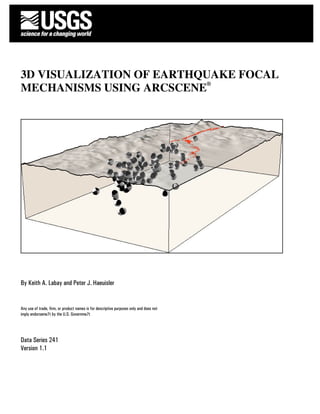
17. 3.0 Example
Figure 16 shows an example image of focal mechanism symbols created by 3D Focal Mechanisms near the epicenter of
the M7.9 2002 Denali Fault earthquake. View is to the northeast. The junction between the Susitna Glacier Thrust Fault and
Denali Fault is shown. Note numerous thrust focal mechanism symbols in the region between the surface rupture of the
Denali Fault and the arc of the Susitna Glacier Thrust Fault. Additional information in this image showing the land surface,
fault location, and the block diagram was added in ArcScene® independent of 3DFM.
Figure 16. Example image of focal mechanism symbols along the Denali Fault and Susitna Glacier Thrust Fault.
4.0 References Cited
Brune, J.N., 1970, Tectonic stress and the spectra of seismic shear waves from earthquakes: Journal
of Geophysical Research, v. 75, no. 26, p. 4997-5009.
Cronin, V.S., 2004, A draft primer on focal mechanism solutions for geologists: Teaching Quantita-
tive Skills in the Geosciences,
http://serc.carleton.edu/files/NAGTWorkshops/structure04/Focal_mechanism_primer.pdf (last
accessed November 15, 2006).
5.0 Acknowledgments
The authors gratefully acknowledge comments on this text and software functionally from Evan Thoms, Luke Blair,
Bill Ellsworth, and Stephanie Prejean.
17