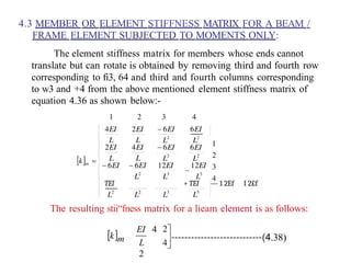
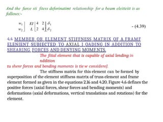
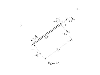
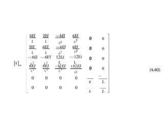
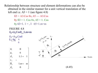
The document presents a detailed analysis of the stiffness method applied to beams and frames in structural engineering. It outlines the derivation of member stiffness matrices for various loading conditions, including shear forces and bending moments, using a combination of equations and diagrams. Key concepts such as transformation matrices and relationships between local and global coordinates are emphasized for understanding and applying structural analysis techniques.

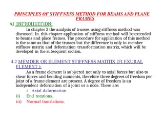
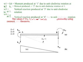
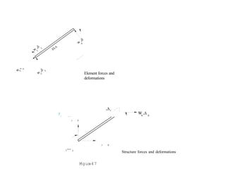
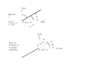
![Consider a member/element shown in figure 4.1. The x-y coordinate system
shown is local coordinate system. Origin is always at the near end. There
are two forces (shear force w3 and a moment w1) acting at near end of the
joint and correspondingly there are two deformations (vertical translations
63, and rotation 81).Similarly there are two forces (shear force w4 and a
moment w2) acting at the far end of the joint and correspondingly two
deformations (vertical translation fi4 and rotation 62).
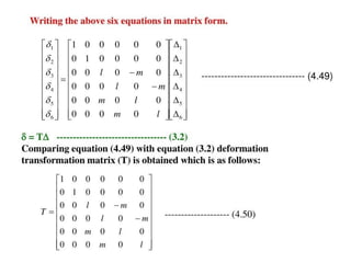
4.2.1 SIGN CONVFNTION
Moments (wI, w2) and rotatioiis (II and H) are positive
ivheii clockWfSC ffltd negative wlten counter clockwise.
Translation fi3, 64 are positive w/ten npwnrd and negative when
downward. The local x-axis runs along the member from the first joint to
the second joint
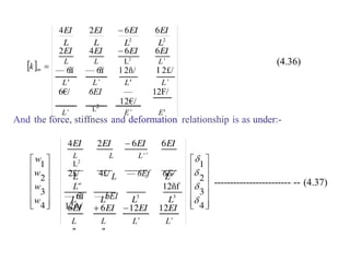
4.2.2 DERIVATION
The load-stiffness-deformation relationship for this element is the same as
that for a truss element as expressed in equation 3.17.
[w]q, = [k]„, [6]„,.--------------------------------- (3.17)
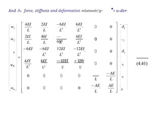
As there are four forces and four corresponding deformations then the
equation 3.17 can be expanded in the following form:](https://image.slidesharecdn.com/matrixppt-241221103457-cb2e30d7/85/MATRIX-POWER-POITN-PRESENTATION-NEW-pptx-4-320.jpg)
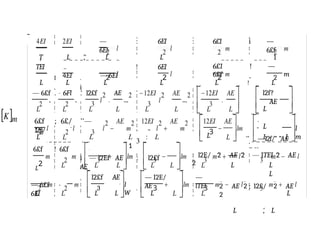
![k, k k,
---------------------------------- (4.1)
Where each element of the stiffness matriE is called stiffness coefficient
as discussed in chapter 2. It represents the place occupied by it with
respect to row and columns. Any stiffness coefficient may be represented
by kij; where i and j are number of rows and columns.
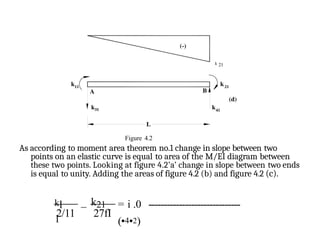
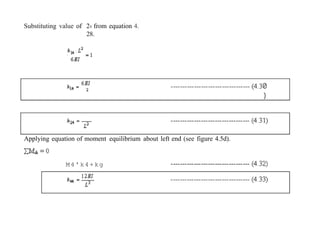
The above mentioned element stiffness matrix [k]m is formed by
applying a unit value of each end deformation in turn and the
corresponding column of the matrix of equation 4.1 gives the various end
forces developed at the member ends while other deformations are
restrained. This procedure is as follows:
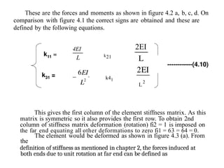
Apply unit positive deformation (clockwise rotation) ôl = 1 and
equating all other deformations to zero (ö2 = fi3 = 64 = 0). The element
would be deformed as shown in figure 4.2.a. From the definition of
stiffness, the forces induced at hoth ends due to unit clockwise rotation of
near end are as under.](https://image.slidesharecdn.com/matrixppt-241221103457-cb2e30d7/85/MATRIX-POWER-POITN-PRESENTATION-NEW-pptx-5-320.jpg)
![, k32'
‘
6EI
2 2 17
)
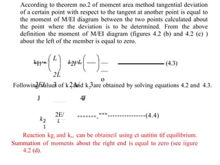
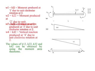
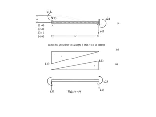
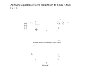
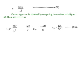
Continuing this process of applying unit vertical translation 63 = 1 and solving
for forces and moments as shown in figure 4.4 (a, b, c, & I) and applying unit vertical
translation 34 = 1 and solving for forces and moments as shown in figure 4.5 (a, b, c & d),
third row., third column, fourth row and fourth column can be obtained.
Following is the
summary of the se calculations.
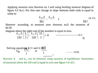
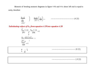
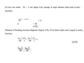
For 5s — I (see figure 4.4a) . change in slop e between both ends is zero.
Therefore
’]3 - ’13
=
2f/ 2 1
(418)
(4
19)](https://image.slidesharecdn.com/matrixppt-241221103457-cb2e30d7/85/MATRIX-POWER-POITN-PRESENTATION-NEW-pptx-14-320.jpg)
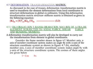
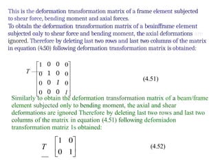
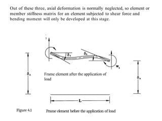
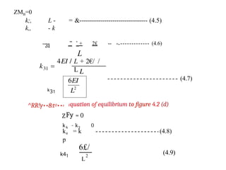
![4.6 iiTRUCTURE STIFFNESS MATRICEii
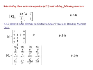
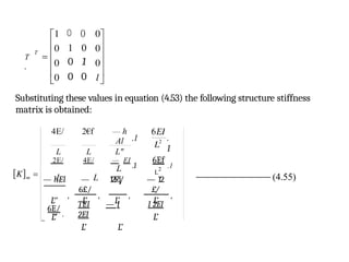
4.fi.1 For a lieam/l'rame element s«$iected to bending moment onlv:
Using the element stiffness matrix and deformation transformation matrix
structure stiffness matrix is formed. Following equation is used for this
purpose:
[K]„, = [T) „ [k] [T]„,
Where,
[T]. = Deformation Trait.sformation matrix
[k]. = Element stillness matrix
In this case:
An
d [k n
EI 4
2
L 2
4 1
0
0
(4.53)
(4.52)
(4.38)](https://image.slidesharecdn.com/matrixppt-241221103457-cb2e30d7/85/MATRIX-POWER-POITN-PRESENTATION-NEW-pptx-38-320.jpg)