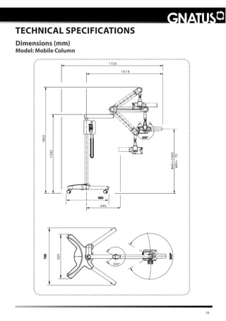
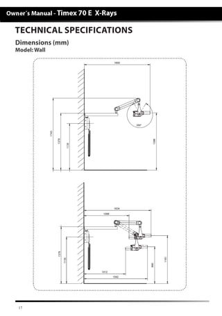
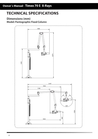
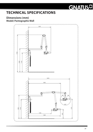
SlideShare a Scribd company logo
1 of 44
Download to read offline
2
PRESENTATION OF MANUAL
EQUIPMENT:
Technical name: Odontological X -Ray
Trade name: Timex 70 E - X-Ray
Brand: GNATUS
Trade models:
• Timex 70 E X-Ray Mobile Column
• Timex 70 E X-Ray Wall
• Timex 70 E X-Ray Pantographic Mobile Column
• Timex 70 E X-Ray Pantographic Wall
• Timex 70 E X-Ray Pantographic Fixed Column
Manufacturer/ Distribuitor:
GNATUS - EQUIPAMENTOS MÉDICO-ODONTOLÓGICOS LTDA.
Rod. Abrão Assed , Km 53+450m - Cx. Postal 782 CEP 14097-500
Ribeirão Preto - S.P. - Brasil
Fone +55 (16) 2102-5000 - Fax +55 (16) 2102-5001
C.N.P.J. 48.015.119/0001-64 - Insc. Est. 582.329.957.115
www.gnatus.com.br - gnatus@gnatus.com.br
Technical Duties: Gilberto Henrique Canesin Nomelini
CREA-SP: 0600891412
Registration ANVISA nº: 10229030030
INSTRUCTIONS OF USE
ATTENTION
For greater safety:
• Read and understand all the instructions contained in these
Instructions for Use before installing or operating this Equipment.
Note: These Instructions for Use must be read by all the operators
of this Equipment.
• This manual was originally written in Portuguese.
• Manual Review: 00
3
INDEX
PRESENTATION OF MANUAL ............................................................................ 02
IDENTIFICATION OF EQUIPMENT..................................................................... 05
-Dear Customer ................................................................................................. 05
-Identification .................................................................................................... 05
-Principles and bases applied to the functioning of the product.................................. 06
-Description of Equipment ................................................................................... 06
-Indication of Equipment ..................................................................................... 06
MODULES, ACCESSORIES, OPTIONS AND MATERIALS OF CONSUMPTION ........ 07
TECHNICAL SPECIFICATIONS .......................................................................... 09
-General Technical specifications ........................................................................... 09
-Cooling ............................................................................................................ 12
-Thermal protection ............................................................................................ 12
-Protection against acidental activation .................................................................. 12
-Under current protection .................................................................................... 12
-Overvoltage Protection ....................................................................................... 12
-Undervoltage Protection .................................................................................... 12
-Trigger ............................................................................................................ 13
-Protection by distance against parasite radiation .................................................... 13
-How to regulate the arm tension ......................................................................... 13
-Radiation quality - Ingress of quality equivalence ................................................... 14
-Parametes for charge exposure............................................................................ 14
-Transmitter assembly.......................................................................................... 15
-Standards applied ............................................................................................. 15
-Dimension ........................................................................................................ 16
-Symbologies of packaging .................................................................................. 21
-Symbologies of product ...................................................................................... 21
-Contents of the accessible and inaccessible markings ............................................. 22
-Tube letters with technical characteristics.............................................................. 26
INSTALLATION OF EQUIPMENT
-Dimensions and positioning Chassis command box X-Ray Wall Model......................... 28
OPERATION OF EQUIPMENT
-Instructions of transmitter assembly operation (how to move the cylinder head) ........ 30
-Operating instructions......................................................................................... 30
-Operating Instructions “Smaller colimator rectangular kit and extension with
colimator cone kit”.............................................................................................. 31
-Limitation and indication of bunch extension of x radiation ..................................... 31
-Precaution to be observed before 1st application of load ......................................... 31
-Bunch radiation characteristics ............................................................................ 32
-Radiographic techniques letters ........................................................................... 33
-Procedure for development with recent chemical reagent ........................................ 33
-Radiographic testing .......................................................................................... 34
PRECAUTIONS, RESTRICTIONS AND WARNINGS
-Conditions of transport and storage ..................................................................... 35
-Environmental conditions of operation .................................................................. 35
-Sensitiveness to environmental conditions foreseeable in normal situations of use ..... 35
-Precautions and warnings “during the installation” of equipment .............................. 35
4
INDEX
-Precommendations for preserving the equipment ................................................... 36
-Precautions and warnings “during the use” of equipment ........................................ 36
-Precautions and warnings “after” the use of equipment .......................................... 37
-Precautions and warnings during the “cleaning and disinfection” of equipment ........... 37
-Precautions in case of alteration in the functioning of equipment ............................. 37
-Precautions to be adopted against foreseeable or uncommon risks, related to the
deactivation and abandoning of equipment ............................................................ 37
CORRECTIVE AND PREVENTIVE MAINTENANCE AND PRESERVATION
-Additional procedures for reuse............................................................................ 38
-Disinfection ...................................................................................................... 38
-Cleaning .......................................................................................................... 38
-Preventive maintenance .................................................................................... 39
-Corrective maintenance ..................................................................................... 39
UNFORESEEN EVENTS – SOLUTION OF PROBLEMS ........................................... 40
WARRANTY OF EQUIPMENT ............................................................................. 41
FINAL CONSIDERATIONS ................................................................................. 41
5
Dear Customer
Congratulations. You have made a good choice when you decided to buy a GNATUS
QUALITY product comparable to the best products available in the World. This manual is a
general presentation of your product and it will give you important details to help you to
solve possible problems.
Please, read it and keep this with you.
Identification
	 Technical name: Odontological X -Ray
	 Trade name: Timex 70 E - X-Ray
	 Trade models:
	 • Timex 70 E X-Ray Mobile Column
	 • Timex 70 E X-Ray Wall
	 • Timex 70 E X-Ray Pantographic Mobile Column
	 • Timex 70 E X-Ray Pantographic Wall
	 • Timex 70 E X-Ray Pantographic Fixed Column
	 Brand: GNATUS
DESCRIPTION OF THE EQUIPMENT
6
This device is for intraoral radiography of patient’s dentition with the purpose of making
a diagnostic.
It is a unit of X- Ray for odontological use, with nominal tension of 70kVp and current
in the tube of
7,0 mA. It has a centesimal digital timer, particularly developed for using with digital
radiographic sensors, it reduces the time of radiation exposure and also it is indicated for
conventional radiographic films.
Fixed column with the option of mobile column with 4-caster base; super steady columns,
painted in epoxy at 250º C, and option of base for mounting on the wall built in steel, painted
in epoxy and covered by a cover in polystyrene of high impact.
It is composed of type-pantographic arm (when pantographic model), which allows
better reach and use in many positions.
Tube (ampoule), with focal point of 0,8 x 0,8mm, filtration with aluminum equivalence
of 3,22 mm, cylindrical guide made in radiopaque polymer in order to avoid secondary
radiations, wound completely immersed in special oil.
Manual trigger at a distance of 5m. Duly tested by legal body, respecting the rules in effect
of radiological protection and elaborated by National Nuclear Energy Commission - CNEN.
The test method for measuring tension parameters of mean peak in the x- ray tube
(kVp), mean current in the x-ray tube (mA), application time of load on x-ray tube(s) and
product current X time in the x-ray time (mAs), adopted is the following:
It is used for measuring the device Dynalyzer III digital display, connected to a high
tension unit. This unit consists of a resistive tension divisor of 1:20.000.
For odontological x-ray equipment it is used an adapter system in order to make a
connection of the device Dynalyzer III. “In order to check the results obtained, it is connected
to high tension unit The digital storage oscilloscope 2230 produced by Tektronix which gives
the possibility to store an electrical signal to which is subject the x-ray tube, thus allowing
an inspection of mean peak in the x-ray tube and the application time of load. Such results
can be compared with those obtained from Dynalyzer III”.
ISO 9001/2000 and ISO 13485/2003 Quality System, assuryng the products are
manufactured under standart procedures.
Products manufactured in agreement with RDC-59 - ANVISA (Sanitary Surveillance
National Agency).
DESCRIPTION OF THE EQUIPMENT
Description of Equipment
Principles and bases applied to the functioning of the product
Photomultipliers set, which are generated in X-rays tubes that transform light energy
into electric energy, and then a circuit set forms the image, in order to diagnose or to guide
evasive medical procedures and dental treatments.
This equipment is for dental use use only. It must be operated and utilized by specialized
professional (certified professional, according to the legislation of the country) and following
the instructions of the manual. The operation of the equipment required, for the professional,
the utilization of correct instruments and it should to be in perfect conditions of the use, and
to protect the professional, the patients and others, in the eventual danger situation.
Indication of Equipment
7
MODULES, ACCESSORIES, OPTIONS AND MATE-
RIALS OF CONSUMPTION
01	-	Radiation transmitter Assembly x (cylinder head)
02	 -	Graduated scale
03	-	Pantographic Arm
04	-	Fixed arm (type Floor)
4A	-	Fixed arm (type Wall)
05	 -	Electronic command
5A	-	Electronic command (type Wall)
06	-	Main switch - On / Off
07	 -	Fuse box
08	-	Distance Control with cable
09	 -	Column
10	-	Power - in cable
11	-	Base (mobile type)
12	 -	Wheels
13	-	Base (fixed type)
14 - Smaller colimator rectangular kit (optional)
15 - Extension with colimator cone kit (optional)
The contents of this page are of an
informative nature, the equipment being
able to differ from that illustrated. So, upon
acquiring the product check the technical
compatibilty between equipment, coupling
and accessories.
Note: This equipment is designed for
stationary use.
14
03
03
03
09
09
05
06
06
07
08
08
08
07
07
06
5A
05
02
02
02
04
4A
01
11
12
10
10
13
01
01
15
8
MODULES, ACCESSORIES, OPTIONS AND MATE-
RIALS OF CONSUMPTION
01	-	Radiation transmitter Assembly x (cylinder head)
02	 -	Graduated scale
3A	-	Adjustable arm
4A	-	Fixed arm (type Wall)
4B	-	Fixed arm (type Mobile)
05	 -	Electronic command
5A	-	Electronic command (type Wall)
06	-	Main switch - On / Off
07	 -	Fuse box
08	-	Distance Control with cable
09	 -	Column
10	-	Power - in cable
11	-	Base (mobile type)
12	 -	Wheels
14 - Smaller colimator rectangular kit (optional)
15 - Extension with colimator cone kit (optional)
The contents of this page are of an
informative nature, the equipment being
able to differ from that illustrated. So, upon
acquiring the product check the technical
compatibilty between equipment, coupling
and accessories.
Note: This equipment is designed for
stationary use.
14
3A3A
09
05
06
07
08
08
07
06
5A
02
02
4B 4A
01
11
12
10
01
15
9
TECHNICAL SPECIFICATIONS
General
Technical features
Model
• Timex 70 E X-Ray Mobile Column
• Timex 70 E X-Ray Wall
• Timex 70 E X-Ray Pantographic Mobile Column
• Timex 70 E X-Ray Pantographic Wall
• Timex 70 E X-Ray Pantographic Fixed Column
Classification of Equipment as per ANVISA:
Class III
Classification of Equipment as per standard IEC 60601-1:
Protection against Electric Shock - Type B and Class I Equipment (IEC 60601-1)
Degree of safety of application in presence:
Equipment not suited to an anesthetic mixture inflammable with air, oxygen or nitrous
oxide.
Mode of Operation
Continuous operation with intermittent load
Protection against Dangerous Ingress of water
Common device (Equip. Closed without protection against ingress o water)
Generator
Immersed in Oil
Transformer Oil
Lubrax Industrial AV-58-BR-Petrobras
Cylindrical Collimator
Totally armored
Target Material
Tungsten
Reference Axis
19o in relation to anode
Target Angle
19o
Nominal Focus Point Value
(0,8 x 0,8mm) positioned in relation to the reference axis of the XR tube in compliance
with IEC336/1982)
10
TECHNICAL SPECIFICATIONS
General
Technical features
Tube Conditioning
At iddle position the Cone should always be directed downwards
kVp tube (average)
70 kVp (for max. tube current 7.0 mA)
kVp (average) beam peak
70 kVp +/- 10%
Net weight Gross weight
Timex 70 E X-Ray Mobile Column
50 kg 64,5 kg
Net weight Gross weight
Timex 70 E X-Ray Wall
25 kg 29 kg
Net weight Gross weight
Timex 70 E X-Ray Pantographic Mobile Column
61,5 kg 75,5 kg
Net weight Gross weight
Timex 70 E X-Ray Pantographic Wall
31 kg 34,5 kg
Net weight Gross weight
Timex 70 E X-Ray Pantographic Fixed Column
35,6 kg 41 kg
Power Supply
Model
Nominal
Tension
Supply
Rate Freq Consumption
Type
Installation
Timex 70 E
Mobile Column
127V~ 125V~ + 4% 60Hz 10A Mobile
220V~ 220V~ + 4% 60Hz 6A Mobile
220V~ 220V~ + 4% 50Hz 6A Mobile
230V~ 230V~ + 4% 50Hz 5,5A Mobile
240V~ 240V~ + 4% 50Hz 5A Mobile
11
Power Power in stand by
1200VA 15VA
No of phase:
Single Phase / Biphasic
Fuses: 127V~ Fuses: 220 à 240V~
F1 and F2 15A delayed action F1 and F2 8A delayed action
F3 0,2A quick action
Type of fuses
Crystal 20 mm
TECHNICAL SPECIFICATIONS
Power Supply
Technical features
Model
Nominal
Tension
Supply
Rate Freq Consumption
Type
Installation
Timex 70 E
Pantographic
Fixed Column /
Wall
127V~ 125V~ + 4% 60Hz 10A Fixed
220V~ 220V~ + 4% 60Hz 6A Fixed
220V~ 220V~ + 4% 50Hz 6A Fixed
230V~ 230V~ + 4% 50Hz 5,5A Fixed
240V~ 240V~ + 4% 50Hz 5A Fixed
Model
Nominal
Tension
Supply
Rate Freq Consumption
Type
Installation
Timex 70 E
Pantographic
Mobile Column
127V~ 125V~ + 4% 60Hz 10A Mobile
220V~ 220V~ + 4% 60Hz 6A Mobile
220V~ 220V~ + 4% 50Hz 6A Mobile
230V~ 230V~ + 4% 50Hz 5,5A Mobile
240V~ 240V~ + 4% 50Hz 5A Mobile
Model
Nominal
Tension
Supply
Rate Freq Consumption
Type
Installation
Timex 70 E Wall
127V~ 125V~ + 4% 60Hz 10A Fixed
220V~ 220V~ + 4% 60Hz 6A Fixed
220V~ 220V~ + 4% 50Hz 6A Fixed
230V~ 230V~ + 4% 50Hz 5,5A Fixed
240V~ 240V~ + 4% 50Hz 5A Fixed
12
TECHNICAL SPECIFICATIONS
Cooling - Sb
Technical features
The device presents protection against excessive heating of the tube.
A new image can be performed only after a time equivalent of 30 times the trigger time,
necessary time for natural cooling and return of normal functions.
Ex: Trigger time = 0,06 seconds.
Cooling time = 0,06seconds X 30 = 1,8 seconds.
Thermal protection
The device has a safety mechanism against temperature elevation of the transmitter
assembly.
A thermal protection turn the device’s functions off if the internal temperature of the
transmitter assembly overpasses the allowed limit , damaging the internal components of
the assembly.
Protection against acidental activation
The equipment has an electronic blocking mechanism against acidental activations,
preventing consecutive activations, eliminating unecessary exposure to radiation and
overheating of the emission set.
Under current protection
The equipment features a safety device for over-current by means of 3 fuses, being 2
of them for power supply and one for electronic circuit.
Overvoltage Protection
The device has a safety mechanism for overvoltage in device power supply that does
not allow trigger when power supply overpasses approximately 3 Volts of specified limits.
Undervoltage Protection
The device has a safety mechanism for undervoltage in device power supply that does
not allow trigger when power supply it goes inferior the 10 V~ of specified limits.
13
TECHNICAL SPECIFICATIONS
Technical features
Distance protection against parasite radiation
The operator must use the safety device of the equipment (distance activation cable),
remaining at a minimum distance of 3 meters from the X-radiation beam during the charge
application. The user must wear the protection clothes (lead apron and lead collar) they
are not provided with the product
Lead apron and collar,
(They are not provided with
the product).
How to regulate arm tension
If the arm assembly/cylinder head loses its balance condition, a Technician authorized
by Gnatus shall be called in order to make the adjustment.
Trigger
The button must be continuously pressed until the end of transmission, monitored by
a sound signal (beep), that is, if the button activation is interrupted, the transmission will
also be automatically interrupted , by indicating at display “A4”.
14
TECHNICAL SPECIFICATIONS
Radiation quality
Ingress of quality
equivalence
Note:
Filtration with thickness equivalency of aluminum.
- Using as method an x-ray tube tension of 70 kVp and 2.5 mmAl of semiconducting
reductor.
-The method using the measurement of the first semireductor layer was in narrow beam
conditions, with the x-ray equipment operating with x-ray tube tension value of 70 kVp with
anodic current of 7mA and exposure time of 1.0 second.
Parametesforchargeexposure
0,32s
OBS.:
The specified field
for time irradiation
c o m p l i a n c e i s
c o m p r e h e n d e d
within 0.06 and 3.2
seconds.
FILTERS Tube crystal
1,26 mm Al
Insulating oil, column 17mm
0,64 mm Al
Window
0,32 mm Al
Additional filter (aluminum)
1,00 mm Al
TOTAL FILTRATION = 3,22 mm Al
Tension
70 kVp ± 10%
Current
7 mA ± 1,5 mA
Power
0,49 kW
Product current time
2,24 mAs
Highest energy applied in intermittent
mode during 1 h
170 KJ
Timex 70E X-Ray
Mili Amper scale X Time
Set
Time
(seconds)
mA c/
Real
Time
Set x Real
KVp AVG
Set
Time
(seconds)
mA c/
Real
Time
Set x Real
KVp AVG
0,06 1,46 81,4 0,56 7,20 70,6
0,07 1,46 80,7 0,63 7,39 70,8
0,08 2,36 79,5 0,71 7,37 70,7
0,1 3,91 79,4 0,8 7,48 70,7
0,12 4,21 76,5 1 7,58 70,7
0,14 4,42 75,8 1,25 7,58 70,6
0,16 4,74 75,1 1,4 7,70 70,7
0,2 5,44 73,7 1,6 7,56 70,6
0,25 5,94 72,6 2 7,69 70,9
0,28 6,30 72,0 2,5 7,80 70,7
0,32 6 ,59 71,5 2,8 7,64 70,0
0,4 6,71 71,0 3,2 70,59 70,7
0,5 6,97 70,6 ----- ----- -----
15
TECHNICAL SPECIFICATIONS
01 - Complementary cone
02 - Aluminum filter (1mm a1)
03 - Collimator
04 - Collimator O-ring
05 - X-ray tube
Transmitter assembly
IMPORTANT: Information referring to x-ray dosage, radiation leak can be found in the
conformity report attached to this manual.
NOTE:
-	The serial number of the dome, beam limiter and radiation source is the same of the
equipment, and it is stated in the product’s label.
Standards applied:
This product was tested and approved as per the standards:
IEC 60601-1: (1988);
Amendment 1: (1993);
Amendment 2: (1995);
IEC 60601-1-2: (2001);
IEC 60601-1-3: (1994);
IEC 60601-2-7: (1998);
IEC 60601-2-28: (1993);
IEC 60601-2-32: (1994);
CISPR 11, edição 3.1 (1999);
IEC 61000-4-2: (2001);
IEC 61000-4-3: (2006);
IEC 61000-4-4: (2004);
IEC 61000-4-5: (2005);
IEC 61000-4-6: (2006);
IEC 61000-4-11: (2004);
NBR-IEC série 601-1 Equipamento Eletromédico - Parte 1: Prescrições gerais para
segurança;
EN 980:2003 (Ed. 2) - Graphical symbols for use in the labelling of medical devices;
ISO 14971: 2007
ISO 9687: 1993 - Dental equipment - graphical symbols;
ISO 7494 - 1:2004 - Dental Units - Port 1: General requeriments and test methods
ISO 13485:2003
ISO 780:1997
ISO 11144:1995
06 - External cover
07 - Insulating oil
08 - Focal point
09 - High tension coil
10 - Electronic plate Assembly
06 05 04
10 09 08 07
03 02 01
16
TECHNICAL SPECIFICATIONS
Dimensions (mm)
Model: Mobile Column
1619
17
TECHNICAL SPECIFICATIONS
Dimensions (mm)
Model: Wall
18
TECHNICAL SPECIFICATIONS
Dimensions (mm)
Model: Pantographic Mobile Column
19
TECHNICAL SPECIFICATIONS
Dimensions (mm)
Model: Pantographic Fixed Column
20
TECHNICAL SPECIFICATIONS
Dimensions (mm)
Model: Pantographic Wall
21
Careful: It indicates an important
instruction for the operation of the
product. Not following it can cause
dangerous malfunctioning.
Note: It indicates useful
information for operation of the
product.
Important: It indicates an
instruction of safety for operation
of the product. Not following it,
can lead to serious danger to the
patient.
Landing (in many parts of the
equipment) indicates the condition
of being landed.
Turned on
Turned off
B type equipment
Product symbols
TECHNICAL SPECIFICATIONS
Trigger Time Indicator Display
and Many messages
x-ray transmission indicator
LED (yellow)
“Focal Point”- indicates the
exact position Of radiation
transmitter center
“Radiation”- indicates that
the device issues Ionizing
radiation
Maximum stacking:
It determines the maximum
quantity of boxes which can be
stacked during transportation
and storage “as per packaging”.
Packing to be transported and / or
stored with the harrows up.
Packing to be transported and /
or stored with care (should not
suffer drop and neither receive
impact).
Packing to be transported and
/ or stored avoiding humidity,
rains and wet floor.
The packing must be stored and
transported away from direct
sun light exposure.
Temperature limit for the
packing to be stored or
transported.
Packing symbols
22
TECHNICAL SPECIFICATIONS
Product symbols
Dangerous electrical tension
Trigger key
Button to reset the display
indicator for x-ray emission
time.
Time selector - decrease Time selector - increase
Content of accessible and non-accessible demarcations
01
02
23
Content of accessible and non-accessible demarcations
TECHNICAL SPECIFICATIONS
03
04
05
24
06 10
07
08 09
Content of accessible and non-accessible demarcations
TECHNICAL SPECIFICATIONS
25
Description Fixation local
01 - Product identification tag Cabinet cover
02 - Product identification tag Cylinder head
03 - Ades. tag. Pantographic Arm Cabinet cover
04 - Ades. tag. Adjustable arm Cabinet cover
05 - Ades tag. radiation Cylinder head
06 - Ades tag. identification Tension Cylinder head Cylinder head
07 - Ades tag. electro medic safety seal Packing and Cylinder head
08 - Product identification tag X-Ray control
09 - Ades tag. - warning Arm articulations and cabinet
cover
10 - Ades tag. – tape removal Arm
Content of accessible and non-accessible demarcations
TECHNICAL SPECIFICATIONS
26
Tube letters with technical characteristics
TECHNICAL SPECIFICATIONS
27
Tube letters with technical characteristics
TECHNICAL SPECIFICATIONS
28
INSTALLATION OF EQUIPMENT
Dimensions and positioning
Chassis command box X-Ray Wall Model
Recommendations for pre-installation preparation of X-Ray
Wall model:
In order to assure the perfect functioning of wall model x-ray,
we recommend that the services of pre-installation be performed
by professionals duly qualified.
Any damages that may occur to the device, caused by fault
at pre-installation will not be covered by warranty.
“For more information, refer to pre-installation manual”.
Chassis positioning related to the floor.
Chassis Dimensional “template for
wall drilling”
Electrical
passage box
Distance
from floor
to first hole
29
INSTALLATION OF EQUIPMENT
- This equipment shall only be able to be unpacked and installed by a Gnatus authorized
technician, under penalty of losing the warranty, as only (s)he has the information, suitable
tools and training required to execute this task.
- Gnatus bears no responsibility for damages or accidents caused by poor installation
executed by a technician not authorized by Gnatus.
- Only after the equipment has been installed and duly tested by the authorized technician
representing Gnatus, will it be ready to start work operations.
OBS: These information also make part of the Manual of Installation
and Maintenance of the equipment that can be found with the
authorized Gnatus technician.
The installation of this equipment requires specialized technical
assistance (Gnatus).
30
OPERATION OF EQUIPMENT
Operating Instructions of Transmitter Assembly How to move
the cylinder head
Operating Instructions
- When moving the cylinder head, grasp the cylinder (02) and back part (01) as shown
in the picture.
Only after an authorized technician have properly installed
and tested the equipment, it will be ready to work.
Verify if the equipment is connected to the main grid.
Turn on the general switch (09) and a green light will
turn on.
Choose the time scale from 0 to 3.2 seconds according
to the work to be performed. “See radiographic technique
chart on page 33” and set it through the buttons (04 and
05) located on the control.
When the patient is properly prepared for the
radiography:
Remove the support control, press the shutter-button
(06) (Beep beeping) and keep it pressed.
The “yellow” LED must be lighted during radiation
emission.
Note: Turn off the general key (09) whenever the
equipment is not in use.
Always keep the remote control in its holder.
Note: If the messages appear on the display:
•	A1 •A2
•	A3 •A4
•Sb	 •A5
01
02
03
04
06
05
07
08
09
NOTE:
The value indicated on the digital command display refers to the exposure time. To
obtain the charge application time, add 0.2 seconds (pre-warming) to any value indicated
on the display.
- As it is a pulse device and depends on the wiring frequency, it is not possible to provide
time of 0,063s belonging to geometric series within the range of ± 10%.
( IEC 60601-2-7 : 29.1.106 E)
See page 40 “Unforeseen situations”
31
OPERATION OF EQUIPMENT
Operating Instructions “Smaller colimator rectangular kit and
extension with colimator cone kit”
WARNING
The operator shall keep a bigger distance between the distal extreme of limiting bunch
device and patient’s surface.
Limit and x-ray beam extension recommendation
The X-Ray field is confined within the limits of opening of the Diaphragm (11,2mm -
fixed).
Precautions to be observed before the 1st charge application
-	Check that all the items from the instructions operations manual have been
concluded.
-	Place yourself behind the head (opposite the beam) at a minimum distance of 2.5m,
to carry out the activation.
By applying a slight effort, press the cover (01) against the adapter (02) observing the
alignment of openings (A) with catches (B) “click system”.
After assembling cover (01) and adaptor (02), attach the assembly mounted in the
complementary cone (03), afterwards attach to the cylinder head (04).
The attachment between the couplings shall be performed with rotation movements,
and the alignment between locking cams shall be observed (C).
BB
AA
C
C
CC
C
0202
04
0101
03
04
E x t e n s i o n w i t h
colimator cone kit
(optional)
S m a l l e r c o l i m a t o r
rectangular kit (optional)
32
OPERATION OF EQUIPMENT
Radiation bunch characteristics
The pictures below present radiation bunch characteristics with and without the use of
extension whit colimador cone.
The extension whit colimador cone is used to apply the parallelism technique which
gives less distortion to the image generated due to x-ray from film/sensor presented less
inclination related to reference axis.
RadiationbunchXwithoutextensionwhitcolimadorcone
(203,2mm)
Radiation bunch X with extension whit colimador cone
(304mm)
NOTE: If the extension whit colimador cone is not used, it does not affect the
safety level to patient during use of this device.
33
OPERATION OF EQUIPMENT
Radiography technical letter
Standard table for exposure time with type E film in adult individuals using the bisector
periapical technique.
DEP - Skin penetration dose (mGy)
DEP - 3,5 mGy - Standard level established by ordinance 453 (D.O.U. 103 02/06/98) for
a periapical exame of typical adult patient and film of group E. (Extaspeed/Agfa M-4)
Film D (Ultra-speed/Agfa M-2) double the time;
Children, con-sider 2/3 of time;
Angle with the vertical.
Procedure for processing with recent chemical agents
Process Temperature (oC) 18 - 20 21 -22 23 - 25 26 - 28 29 - 31
Process Time (min) 5,0 4,0 3,0 2,0 1,0
Region Angle
Time
(E group film)
DEP
(mGy)
Time
(Digital Sensor)
DEP
(mGy)
Superior Jaw
Incisor
Canine
Pre-molar
Molar
+40º
+45º
+30º
+20º
0,32 - 0,40
0,40 - 0,50
0,40 - 0,50
0,50 - 0,64
1,1 - 1,5
1,5 - 2,0
1,5 - 2,0
2,0 - 2,6
0,06
0,08
0,08
0,10
0,10
0,16
0,16
0,24
Lower Jaw
Incisor
Canine
Pre-molar
Molar
-15º
-20º
-10º
-5º
0,32 - 0,40
0,32 - 0,40
0,32 - 0,40
0,40 - 0,50
1,1 - 1,5
1,1 - 1,5
1,1 - 1,5
1,5 - 2,0
0,06
0,06
0,06
0,08
0,10
0,10
0,10
0,16
Bitewing
Anterior
Posterior
+8º
+8º
0,32 - 0,40
0,32 - 0,40
1,1 - 1,5
1,1 - 1,5
0,06
0,06
0,10
0,10
Oclusal
Upper Jaw
Lower Jaw
+60º
-70º
0,50 - 0,63
0,40 - 0,50
2,0 - 2,6
1,5 - 2,0
---
---
---
---
34
OPERATION OF EQUIPMENT
Radiography test
Radiography carried out with
• Kodak Film.
• Ektaspeed Type
After the assembly of the equipment the authorized
technician must carry out a radiography test, using
the materials (film, dark room, processor and fixator)
supplied by the client, following the instructions
below:
Place the head directed downwards (90o position)
next to an horizontal surface (aprox. 50 mm).
Centralize the film (25) utilizing for such the
auxilliary points (24) existing on the Collimator Cylinder
(23), put over the film (25), a metallic object (26). (Ex.:
clips or coin) as in the figure below:
Select a time scale of 0.32 seconds.
Activate the button “Start” (06) (see pg. 30).
23
26
24
25
Caution:
Never test the device with the cylinder aimed to you, or people that are next to the place
Always do the test with the cylinder aimed downwards, by keeping a minimum distance
of 2m.
NOTE:
The material (clips, coins, film, etc) will not be
contaminated, and can be taken out after trigger.
Develop the film at Dark Room with the following
times:
- 1 minute at development;
- 1 minute at fixation.
Afterwards, check if radiography is according to indicated
standard.
In case of differences in comparison, see page 40
“fault”.
If it is not possible to test by the authorized technician
(because of lack of material) the proprietary will be
responsible for it before initiating operations.It is not provided with the product
35
- The equipment has been planned not to be sensitive to interference such as magnetic
fields, external electrical factors, electrostatic discharge, pressure or variance of pressure,
provided that the equipment is installed, maintained, clean, preserved, transported and
operated as per this instruction for use.
- The equipment should only be installed by Gnatus authorized technical assistance or
technicians.
-	 Check that the socket in which the device will be connected has a ground connection.
According to the ABNT standard, this is essential for the safe operation of the system;
- Position the unit in a place where it will not get wet.
-	Install the unit in a place where it will not be damaged by the pressure, temperature,
humidity, direct sunlight, dust, salts, or sulfur compounds.
- The unit should not be submitted to inclination, excessive vibrations, or blows (including
during transportation and handling).
	 Removing the tape from the arm:
- If you early remove the adhesive tape, safety risk may occur. In order to remove it,
please press the adjustable arm taking pressure off the tape. After removing it, slowly
loose the arm.
- The equipment should be transported with the arms overlaid as illustrated. In this form
it will have its stability enhanced.
- This equipment was not planned for use in an environment where vapors, anesthetic
mixtures inflammable with air, or oxygen and nitrous oxide can be detected.
- Check the voltage of the equipment at the moment of executing the electrical
installation.
- The equipment must be grounded correctly.
-	Before the first use and/or after long interruptions from work such as vacations, clean
and disinfect the equipment.
Sensitivity to environmental conditions in normal situations
of use
Precautions and warnings “during the installation” of
quipment
PRECAUTIONS, RESTRICTIONS AND WARNINGS
	 This equipment must be transported and stored observing the following directions:
-	Avoid falls and impacts;
-	Keep it dry, do not expose it to rain, water drops or wet floor;
-	Keep it away from water and direct sunlight, and in it original wrapping;
-	Don’t move it over irregular surfaces, protect it from rain and observe the maximum
stack quantity specified in the packaging;
-	Transportation and storage temperature range: -12°C to 50°C;
-	Transportation and storage relative humidity range: 0°C to 90°C;
-	Atmospheric pressure range: 500hPa to 1060hPa (375 mmHg to 795 mmHg).
-	Ambient temperature range: +5°C to +45°C;
-	Ambient temperature range recommended by Gnatus: +15°C to +30°C;
- Operation relative humidity range: 30% to 75% (non condensing);
- Atmospheric pressure range: 700 hPa to 1060 hPa (525 mmHg to 795 mmHg).
Operation ambient conditions
Transportation and storage
36
- The equipment should only be operated by duly enabled and trained technicians (Dental
Surgeons, Capacitated Professionals)
- If any maintenance should be required, only use services of the Gnatus Authorized
Technical Assistance.
- The equipment has been manufactured to handle both continuous and intermittent
operation; so follow the cycles described in these Instructions for Use.
-	Because of the emission of ionised radiation, this equipment can cause collateral effects
in case users don’t follow the protection requirements.
-	In case of oil spilling in the Emission Set, the precautions below must be carried out:
-	Avoid skin extended contact; wash the contaminated parts with soap and water.
-	In case of skin or eyes irritation, visit a doctor.
-	Do not throw it into water, soil or sewage. In case of spilling, absorb it with sawdust
or similar material.
-	The used oil is recyclable. For disposal, send the oil for re-refining according to the
local law. Preserve the environment.
- Although this equipment has been planned in accordance with the standards of
electromagnetic compatibility, it can, in very extreme conditions, cause interference with
other equipment. Do not use this equipment together with other devices very sensitive to
interference or with devices which create high electromagnetic disturbance.
- Do not expose the plastic parts to contact with chemical substances, use in the routines
of dental treatment, such as: acids, mercury, acrylic liquids, amalgams, etc.
Gnatus shall not be responsible for:
- Use of the equipment differing from that for which it is intended.
- Damages caused to the equipment, the professional and/or the patient by the incorrect
installation and erroneous procedures of maintenance, differing from those described in these
Instructions for use which come with the equipment or by the incorrect operation of it.
PRECAUTIONS, RESTRICTIONS AND WARNINGS
Precautions and warnings“during the use”of equipment
Recommendations for the dental equipment maintenance
Your Gnatus equipment has been designed and developed according to the standards
of modern techology. Similarly to other kinds of equipment, it requires special care, which
is many times neglected due to several reasons and circunstances.
Therefore, here are some important reminders for your daily routine. Try to follow these
simple rules, which will save you a lot of time and will avoid unnecessary expenses once
they start making part of your working procedure.
These information also make part of the Manual of Installation and
Maintenance of the equipment that can be found with the authorized
Gnatus technician.
37
- Before cleaning the equipment, turn off the main switch.
- Avoid spilling water, even accidentally, or other liquids inside the equipment, which
could cause short circuits.
- Do not use microabrasive material or steel wool when cleaning, or employ organic
solvents or detergents which contain solvents such as ether, stain remover, gasoline etc.
Precautionsandwarningsduringthe“cleaninganddisinfection”
of equipment
PRECAUTIONS, RESTRICTIONS AND WARNINGS
- If the equipment has any abnormality, check if the problem is related to any item
listed in the topic of unforeseen events (failures, causes and solutions). If it is not possible
to resolve the problem, turn off the equipment, remove the power supply cable from the
socket and contact your representative (Gnatus).
In order to avoid environmental contamination or undue use of the Equipment after it
has become useless, it should be discarded in the suitable place (as per the local legislation
of the country).
- Pay attention to the local legislation of the country for the conditions of installation
and disposal of residue.
Precautions in case of alteration in the functioning of
equipment
Precautions to be adopted against foreseeable or uncommon
risks, related to the deactivation and abandoning of
equipment
Precautions and warnings“after”the use of equipment
- Turn off the main switch of the dental set when it is not in use for an extended period
of time.
- Always maintain the equipment clean for the next operation.
- Do not modify any part of the equipment. Do not disconnect the cable or other
connections without need.
- After using the equipment, clean and disinfect all the parts which may be in contact
with the patient.
- When using the equipment,
take care with the parts that
can clamp your fingers as
illustrated.
38
The cleaning procedure below should be executed at the start of the
working day and after each patient.
Always turn off the main switch before executing the procedures of
daily maintenance.
CORRECTIVE AND PREVENTIVE MAINTENANCE
AND PRESERVATION
The equipment can be reused in undetermined, i.e. unlimited, quantities, only needing
to be cleaned and disinfected.
Additional procedures for reuse
Cleaning
NOTE: The registration at the Ministry of Health of the
“BactSpray” is executed separately from the product described in
this manual, as the “BactSpray” is not manufactured by Gnatus.
Note: Use gloves
and other systems of
protection, during the
disinfection.
Attention: Do not use any
disinfectant spray, as the
vapor may be inflammable, or
it may cause injury.
Disinfection
Use clean and soft cloth dampened in alcohol 70% to disinfection of the equipment.
Never use corrosive disinfectants or solvents.
To clean the equipment, we recommend the use of “BactSpray
(Reg nº MS: 3.2079.0041.001-5) or any other similar product:
Active component: Benzalkonium chloride (tri-quaternary
ammonium)
Solution 50%................................................. 0.329%
Chemical composition: Butyl Glycol, Decyl polyglucose, Sodium
Benzoate, Sodium Nitrate, Essence, Deodorized Propane / Butane,
demineralized Water.
For more information concerning cleaning procedures, see
manufacturer’s instructions.
WARNING:
- In order to prevent risks and damages to equipment, make
sure that the liquid does not enter into the unit.
- The application of other solvent-based cleaning products or
sodium hypochloride isn’t recommended, because they may damage
the equipment.
39
CORRECTIVE AND PREVENTIVE MAINTENANCE
AND PRESERVATION
The equipment should be calibrated routinely, as per the legislation in force in the
country.
But never with a period exceeding 3 years.
In order to protect your equipment, seek Gnatus technical assistance for periodic revisions
of preventive maintenance.
If the equipment has any abnormality, check if the problem is related to any of the items
listed in the item Unforeseen Events (situation, cause and solution).
If it is not possible to solve the problem, turn off the equipment, and request Gnatus
technical assistance.
Corrective Maintenance
Preventive Maintenance
40
Problem Probable cause Solution
- Not functioning pro-
perly.
-0Damaged fuse.
-0Lack of power.
-Turn the device off and call a tech-
nician.
-Check the wiring
-At radiography appe-
ars a semi circle.
-Wrong positioning of cylin-
der.
-Radiograph using the parallelism
technique, using for that auxiliary
lines of collimator cylinder.
-Radiography totally
dark.
-Excess of XR time;
-Development;	
-Developer with inadequate
temperature.
-Developer with inadequate
mixture.
- Check if the time is well adjusted
according to radiographic techni-
ques table;
-Check the development time.
-AThe quicker is the developer
action the bigger is the solution
temperature.
-Prepare the mixture again.
NOTE: Kodak developer does not
use mixture.
-Radiography with a
dark targe.
-Development Camera with
light penetration.
-Avoid light output.
Message in the Display
-A1
-A2
-A3/A5
-A4
-Sb
-Invalid Voltage:
Voltage higher than the
equipment’s limit.
-Invalid Voltage:
Voltage lower than the
equipment’s limit.
-Fault in electrical network
-Exposure error:
Shutter button released be-
fore time.
-Protection against excessi-
ve tube heating.
-Check the supply voltage
-See about overpotential protection
on page 12.
-Check the supply voltage
-See about overpotential protection
on page 12.
-Turn on the equipment. In case of
failure lasts, request a technician
service.
-Turn on the equipment.
-Wait for the correct cooling time to
reestablish the normal functions –
see page 12 – cooling item.
Upon coming across any problem in operation, follow the instructions below to
check and repair the problem, and/or get in touch with your representative.
UNFORESEENEVENTS–SOLUTIONOFPROBLEMS
41
WARRANTY OF EQUIPMENT
This equipment is covered by the warranty terms counting from the date of installation,
as specified below; provided that the defect has occurred in normal conditions of use and
that the equipment has not remained stored for more than 06 months counting from the
issue date of the sales document until the date of the actual installation.
- WARRANTY TERMS: Verify the guarantee certificate;
- LOSS OF THE WARRANTY:
A) Attempt to repair using an inadequate tool or by unauthorized technicians;
B) Installation of the equipment by an unauthorized technician;
C) Damage arising from inappropriate storage or signs of infringement;
D) Incorrect use of the equipment;
E) Use of a cleaning product not indicated by the factory;
F) Falls or blows which the equipment may undergo or lack of observation of an compliance
with the guidelines of the Owner’s Manual, which was delivered with the present document,
together with the equipment. Repair or replacement of parts during the warranty period
shall not extend the validity term of their warranty.
- This warranty doe snot exempt the customer from paying the service charge for the visit
and the travel expenses of the technician, except when the customer sends the equipment
to execute the maintenance inside the establishment of the technical assistance.
“Consumer Defense Code - art. 50, unique paragraph”.
- The Warranty Certificate comes with the product and must be filled in upon the date
of installation by the Gnatus Authorized Technician.
- Queries and information: GNATUS Help Desk (+55) 16 2102-5000.
- Check the warranty term attached to this manual.
The most important aspect related to equipment care is that concerning spare parts.
To guarantee the life span of your equipment, use only original Gnatus spare parts.
They are sure to follow the technical specifications and standards required by Gnatus.
We must also point out to you our chain of authorized dealers. Only dealers that make
part of this chain will be able to keep your equipment constantly new for they count on
technical assistants who have been trained and on spedific tools for the correct maintenance
of your equipment.
Doubts and information: GNATUS Call center (55-16) 2102-5000.
FINAL CONSIDERATIONS
42
43
Manual rayos-x timex 70

More Related Content

What's hot

8 estabilidad multimaquinas
8 estabilidad multimaquinas8 estabilidad multimaquinas
8 estabilidad multimaquinas
Luis724f
 
Flexible AC Transmission Sytstem
Flexible AC Transmission Sytstem Flexible AC Transmission Sytstem
Flexible AC Transmission Sytstem
ganeshbehera6
 
37133978 conductores-electricos
37133978 conductores-electricos37133978 conductores-electricos
37133978 conductores-electricos
treborsito
 
A practical primer for paralleling electric systems
A practical primer for paralleling electric systemsA practical primer for paralleling electric systems
A practical primer for paralleling electric systems
Javier Maldonado Adco
 
ACTIVE vs PASSIVE HARMONICS FILTERS
ACTIVE vs PASSIVE HARMONICS FILTERSACTIVE vs PASSIVE HARMONICS FILTERS
ACTIVE vs PASSIVE HARMONICS FILTERS
J A Simon
 
Resistive transducers and Strain Gauge
Resistive transducers and Strain GaugeResistive transducers and Strain Gauge
Resistive transducers and Strain Gauge
karoline Enoch
 

What's hot (20)

8 estabilidad multimaquinas
8 estabilidad multimaquinas8 estabilidad multimaquinas
8 estabilidad multimaquinas
 
Flexible AC Transmission Sytstem
Flexible AC Transmission Sytstem Flexible AC Transmission Sytstem
Flexible AC Transmission Sytstem
 
Micro electro-mechanical-systems-based-sensors
Micro electro-mechanical-systems-based-sensorsMicro electro-mechanical-systems-based-sensors
Micro electro-mechanical-systems-based-sensors
 
DigSILENT PF - 06 ejercicios entrenamiento básico
DigSILENT PF - 06 ejercicios entrenamiento básicoDigSILENT PF - 06 ejercicios entrenamiento básico
DigSILENT PF - 06 ejercicios entrenamiento básico
 
37133978 conductores-electricos
37133978 conductores-electricos37133978 conductores-electricos
37133978 conductores-electricos
 
Infrared Plastic Solar Cell
Infrared Plastic Solar CellInfrared Plastic Solar Cell
Infrared Plastic Solar Cell
 
A practical primer for paralleling electric systems
A practical primer for paralleling electric systemsA practical primer for paralleling electric systems
A practical primer for paralleling electric systems
 
Voltage stability using Series FACTS devices
Voltage stability using Series FACTS devicesVoltage stability using Series FACTS devices
Voltage stability using Series FACTS devices
 
Modulos fotovoltaicos
Modulos fotovoltaicosModulos fotovoltaicos
Modulos fotovoltaicos
 
MAGNETIC OPTICAL CURRENT TRANSFORMER
MAGNETIC OPTICAL CURRENT TRANSFORMERMAGNETIC OPTICAL CURRENT TRANSFORMER
MAGNETIC OPTICAL CURRENT TRANSFORMER
 
Exp 4 (1)4. Gauss Siedal Load flow analysis using Matlab Software.
Exp 4 (1)4.	Gauss Siedal Load flow analysis using Matlab Software.Exp 4 (1)4.	Gauss Siedal Load flow analysis using Matlab Software.
Exp 4 (1)4. Gauss Siedal Load flow analysis using Matlab Software.
 
Sistemas de generacion y transmision electrica
Sistemas de generacion y transmision electricaSistemas de generacion y transmision electrica
Sistemas de generacion y transmision electrica
 
Tutor logo!
Tutor logo!Tutor logo!
Tutor logo!
 
ACTIVE vs PASSIVE HARMONICS FILTERS
ACTIVE vs PASSIVE HARMONICS FILTERSACTIVE vs PASSIVE HARMONICS FILTERS
ACTIVE vs PASSIVE HARMONICS FILTERS
 
Fallas simetricas
Fallas simetricasFallas simetricas
Fallas simetricas
 
A dual active bridge dc-dc converter for application in a smart user network
A dual active bridge dc-dc converter for application in a smart user networkA dual active bridge dc-dc converter for application in a smart user network
A dual active bridge dc-dc converter for application in a smart user network
 
Resistive transducers and Strain Gauge
Resistive transducers and Strain GaugeResistive transducers and Strain Gauge
Resistive transducers and Strain Gauge
 
Componentes de un sistema electrico de potencia
Componentes de un sistema electrico de potenciaComponentes de un sistema electrico de potencia
Componentes de un sistema electrico de potencia
 
Chapter17.ppt
Chapter17.pptChapter17.ppt
Chapter17.ppt
 
Equal Area Criterion for Transient Stability Studynew.pptx
Equal Area Criterion for Transient Stability Studynew.pptxEqual Area Criterion for Transient Stability Studynew.pptx
Equal Area Criterion for Transient Stability Studynew.pptx
 

Similar to Manual rayos-x timex 70

8860039 c tri carb reference manual
8860039 c tri carb reference manual8860039 c tri carb reference manual
8860039 c tri carb reference manual
Mahbubul Hassan
 

Similar to Manual rayos-x timex 70 (20)

Jerome 431 manual
Jerome 431 manualJerome 431 manual
Jerome 431 manual
 
Liquiline cm42 endress+hauser datasheet
Liquiline cm42 endress+hauser datasheetLiquiline cm42 endress+hauser datasheet
Liquiline cm42 endress+hauser datasheet
 
Micropilot fmr50 endress+hauser datasheet-free space radar
Micropilot fmr50 endress+hauser datasheet-free space radarMicropilot fmr50 endress+hauser datasheet-free space radar
Micropilot fmr50 endress+hauser datasheet-free space radar
 
Electromagnetic flowmeter - Proline Promag 50H, 53H
Electromagnetic flowmeter - Proline Promag 50H, 53HElectromagnetic flowmeter - Proline Promag 50H, 53H
Electromagnetic flowmeter - Proline Promag 50H, 53H
 
Proline prosonic flow 91 w endress+hauser datasheet-ultrasonic flowmeter
Proline prosonic flow 91 w endress+hauser datasheet-ultrasonic flowmeterProline prosonic flow 91 w endress+hauser datasheet-ultrasonic flowmeter
Proline prosonic flow 91 w endress+hauser datasheet-ultrasonic flowmeter
 
Ultrasonic flowmeter-Drinking water and process water
Ultrasonic flowmeter-Drinking water and process waterUltrasonic flowmeter-Drinking water and process water
Ultrasonic flowmeter-Drinking water and process water
 
Ceraphant t ptc31 ptp31 ptp35-endress+hauser datasheet-pressure measurement
Ceraphant t ptc31 ptp31 ptp35-endress+hauser datasheet-pressure measurementCeraphant t ptc31 ptp31 ptp35-endress+hauser datasheet-pressure measurement
Ceraphant t ptc31 ptp31 ptp35-endress+hauser datasheet-pressure measurement
 
Ultrasonic flowmeter-Clamp on flow measurement
Ultrasonic flowmeter-Clamp on flow measurementUltrasonic flowmeter-Clamp on flow measurement
Ultrasonic flowmeter-Clamp on flow measurement
 
Ultrasonic Level Measurement-Prosonic T FMU30
Ultrasonic Level Measurement-Prosonic T FMU30Ultrasonic Level Measurement-Prosonic T FMU30
Ultrasonic Level Measurement-Prosonic T FMU30
 
Prosonic t fmu30 endress+hauser datasheet-ultrasonic level measurement
Prosonic t fmu30 endress+hauser datasheet-ultrasonic level measurementProsonic t fmu30 endress+hauser datasheet-ultrasonic level measurement
Prosonic t fmu30 endress+hauser datasheet-ultrasonic level measurement
 
Flowmeter Promag 55S-Electromagnetic-Endress Hauser
Flowmeter Promag 55S-Electromagnetic-Endress HauserFlowmeter Promag 55S-Electromagnetic-Endress Hauser
Flowmeter Promag 55S-Electromagnetic-Endress Hauser
 
Ultrasonic flowmeter-Chemical or process applications
Ultrasonic flowmeter-Chemical or process applicationsUltrasonic flowmeter-Chemical or process applications
Ultrasonic flowmeter-Chemical or process applications
 
1093012 l dailyqa3_ug_s
1093012 l dailyqa3_ug_s1093012 l dailyqa3_ug_s
1093012 l dailyqa3_ug_s
 
1093012 l dailyqa3_ug_s
1093012 l dailyqa3_ug_s1093012 l dailyqa3_ug_s
1093012 l dailyqa3_ug_s
 
Level radar measurement in liquids-Micropilot FMR50
Level radar measurement in liquids-Micropilot FMR50Level radar measurement in liquids-Micropilot FMR50
Level radar measurement in liquids-Micropilot FMR50
 
In ultramat 23
In ultramat  23In ultramat  23
In ultramat 23
 
Capacitance level measurement-Liquicap M FMI51, FMI52
Capacitance level measurement-Liquicap M FMI51, FMI52Capacitance level measurement-Liquicap M FMI51, FMI52
Capacitance level measurement-Liquicap M FMI51, FMI52
 
Ultrasonic flowmeter-Drinking water, wastewater and process water.
Ultrasonic flowmeter-Drinking water, wastewater and process water.Ultrasonic flowmeter-Drinking water, wastewater and process water.
Ultrasonic flowmeter-Drinking water, wastewater and process water.
 
Prosonic flow 91 wa1 clamp on endress+hauser datasheet-ultrasonic flowmeter
Prosonic flow 91 wa1 clamp on endress+hauser datasheet-ultrasonic flowmeterProsonic flow 91 wa1 clamp on endress+hauser datasheet-ultrasonic flowmeter
Prosonic flow 91 wa1 clamp on endress+hauser datasheet-ultrasonic flowmeter
 
8860039 c tri carb reference manual
8860039 c tri carb reference manual8860039 c tri carb reference manual
8860039 c tri carb reference manual
 

Recently uploaded

electrical installation and maintenance.
electrical installation and maintenance.electrical installation and maintenance.
electrical installation and maintenance.
benjamincojr
 
21P35A0312 Internship eccccccReport.docx
21P35A0312 Internship eccccccReport.docx21P35A0312 Internship eccccccReport.docx
21P35A0312 Internship eccccccReport.docx
rahulmanepalli02
 
Artificial intelligence presentation2-171219131633.pdf
Artificial intelligence presentation2-171219131633.pdfArtificial intelligence presentation2-171219131633.pdf
Artificial intelligence presentation2-171219131633.pdf
Kira Dess
 

Recently uploaded (20)

Instruct Nirmaana 24-Smart and Lean Construction Through Technology.pdf
Instruct Nirmaana 24-Smart and Lean Construction Through Technology.pdfInstruct Nirmaana 24-Smart and Lean Construction Through Technology.pdf
Instruct Nirmaana 24-Smart and Lean Construction Through Technology.pdf
 
litvinenko_Henry_Intrusion_Hong-Kong_2024.pdf
litvinenko_Henry_Intrusion_Hong-Kong_2024.pdflitvinenko_Henry_Intrusion_Hong-Kong_2024.pdf
litvinenko_Henry_Intrusion_Hong-Kong_2024.pdf
 
15-Minute City: A Completely New Horizon
15-Minute City: A Completely New Horizon15-Minute City: A Completely New Horizon
15-Minute City: A Completely New Horizon
 
NO1 Best Powerful Vashikaran Specialist Baba Vashikaran Specialist For Love V...
NO1 Best Powerful Vashikaran Specialist Baba Vashikaran Specialist For Love V...NO1 Best Powerful Vashikaran Specialist Baba Vashikaran Specialist For Love V...
NO1 Best Powerful Vashikaran Specialist Baba Vashikaran Specialist For Love V...
 
UNIT-2 image enhancement.pdf Image Processing Unit 2 AKTU
UNIT-2 image enhancement.pdf Image Processing Unit 2 AKTUUNIT-2 image enhancement.pdf Image Processing Unit 2 AKTU
UNIT-2 image enhancement.pdf Image Processing Unit 2 AKTU
 
Autodesk Construction Cloud (Autodesk Build).pptx
Autodesk Construction Cloud (Autodesk Build).pptxAutodesk Construction Cloud (Autodesk Build).pptx
Autodesk Construction Cloud (Autodesk Build).pptx
 
5G and 6G refer to generations of mobile network technology, each representin...
5G and 6G refer to generations of mobile network technology, each representin...5G and 6G refer to generations of mobile network technology, each representin...
5G and 6G refer to generations of mobile network technology, each representin...
 
electrical installation and maintenance.
electrical installation and maintenance.electrical installation and maintenance.
electrical installation and maintenance.
 
analog-vs-digital-communication (concept of analog and digital).pptx
analog-vs-digital-communication (concept of analog and digital).pptxanalog-vs-digital-communication (concept of analog and digital).pptx
analog-vs-digital-communication (concept of analog and digital).pptx
 
21P35A0312 Internship eccccccReport.docx
21P35A0312 Internship eccccccReport.docx21P35A0312 Internship eccccccReport.docx
21P35A0312 Internship eccccccReport.docx
 
CLOUD COMPUTING SERVICES - Cloud Reference Modal
CLOUD COMPUTING SERVICES - Cloud Reference ModalCLOUD COMPUTING SERVICES - Cloud Reference Modal
CLOUD COMPUTING SERVICES - Cloud Reference Modal
 
Raashid final report on Embedded Systems
Raashid final report on Embedded SystemsRaashid final report on Embedded Systems
Raashid final report on Embedded Systems
 
Software Engineering Practical File Front Pages.pdf
Software Engineering Practical File Front Pages.pdfSoftware Engineering Practical File Front Pages.pdf
Software Engineering Practical File Front Pages.pdf
 
SLIDESHARE PPT-DECISION MAKING METHODS.pptx
SLIDESHARE PPT-DECISION MAKING METHODS.pptxSLIDESHARE PPT-DECISION MAKING METHODS.pptx
SLIDESHARE PPT-DECISION MAKING METHODS.pptx
 
The Entity-Relationship Model(ER Diagram).pptx
The Entity-Relationship Model(ER Diagram).pptxThe Entity-Relationship Model(ER Diagram).pptx
The Entity-Relationship Model(ER Diagram).pptx
 
Interfacing Analog to Digital Data Converters ee3404.pdf
Interfacing Analog to Digital Data Converters ee3404.pdfInterfacing Analog to Digital Data Converters ee3404.pdf
Interfacing Analog to Digital Data Converters ee3404.pdf
 
Artificial intelligence presentation2-171219131633.pdf
Artificial intelligence presentation2-171219131633.pdfArtificial intelligence presentation2-171219131633.pdf
Artificial intelligence presentation2-171219131633.pdf
 
Maximizing Incident Investigation Efficacy in Oil & Gas: Techniques and Tools
Maximizing Incident Investigation Efficacy in Oil & Gas: Techniques and ToolsMaximizing Incident Investigation Efficacy in Oil & Gas: Techniques and Tools
Maximizing Incident Investigation Efficacy in Oil & Gas: Techniques and Tools
 
Adsorption (mass transfer operations 2) ppt
Adsorption (mass transfer operations 2) pptAdsorption (mass transfer operations 2) ppt
Adsorption (mass transfer operations 2) ppt
 
Working Principle of Echo Sounder and Doppler Effect.pdf
Working Principle of Echo Sounder and Doppler Effect.pdfWorking Principle of Echo Sounder and Doppler Effect.pdf
Working Principle of Echo Sounder and Doppler Effect.pdf
 

Manual rayos-x timex 70

  • 1.
  • 2. 2 PRESENTATION OF MANUAL EQUIPMENT: Technical name: Odontological X -Ray Trade name: Timex 70 E - X-Ray Brand: GNATUS Trade models: • Timex 70 E X-Ray Mobile Column • Timex 70 E X-Ray Wall • Timex 70 E X-Ray Pantographic Mobile Column • Timex 70 E X-Ray Pantographic Wall • Timex 70 E X-Ray Pantographic Fixed Column Manufacturer/ Distribuitor: GNATUS - EQUIPAMENTOS MÉDICO-ODONTOLÓGICOS LTDA. Rod. Abrão Assed , Km 53+450m - Cx. Postal 782 CEP 14097-500 Ribeirão Preto - S.P. - Brasil Fone +55 (16) 2102-5000 - Fax +55 (16) 2102-5001 C.N.P.J. 48.015.119/0001-64 - Insc. Est. 582.329.957.115 www.gnatus.com.br - gnatus@gnatus.com.br Technical Duties: Gilberto Henrique Canesin Nomelini CREA-SP: 0600891412 Registration ANVISA nº: 10229030030 INSTRUCTIONS OF USE ATTENTION For greater safety: • Read and understand all the instructions contained in these Instructions for Use before installing or operating this Equipment. Note: These Instructions for Use must be read by all the operators of this Equipment. • This manual was originally written in Portuguese. • Manual Review: 00
  • 3. 3 INDEX PRESENTATION OF MANUAL ............................................................................ 02 IDENTIFICATION OF EQUIPMENT..................................................................... 05 -Dear Customer ................................................................................................. 05 -Identification .................................................................................................... 05 -Principles and bases applied to the functioning of the product.................................. 06 -Description of Equipment ................................................................................... 06 -Indication of Equipment ..................................................................................... 06 MODULES, ACCESSORIES, OPTIONS AND MATERIALS OF CONSUMPTION ........ 07 TECHNICAL SPECIFICATIONS .......................................................................... 09 -General Technical specifications ........................................................................... 09 -Cooling ............................................................................................................ 12 -Thermal protection ............................................................................................ 12 -Protection against acidental activation .................................................................. 12 -Under current protection .................................................................................... 12 -Overvoltage Protection ....................................................................................... 12 -Undervoltage Protection .................................................................................... 12 -Trigger ............................................................................................................ 13 -Protection by distance against parasite radiation .................................................... 13 -How to regulate the arm tension ......................................................................... 13 -Radiation quality - Ingress of quality equivalence ................................................... 14 -Parametes for charge exposure............................................................................ 14 -Transmitter assembly.......................................................................................... 15 -Standards applied ............................................................................................. 15 -Dimension ........................................................................................................ 16 -Symbologies of packaging .................................................................................. 21 -Symbologies of product ...................................................................................... 21 -Contents of the accessible and inaccessible markings ............................................. 22 -Tube letters with technical characteristics.............................................................. 26 INSTALLATION OF EQUIPMENT -Dimensions and positioning Chassis command box X-Ray Wall Model......................... 28 OPERATION OF EQUIPMENT -Instructions of transmitter assembly operation (how to move the cylinder head) ........ 30 -Operating instructions......................................................................................... 30 -Operating Instructions “Smaller colimator rectangular kit and extension with colimator cone kit”.............................................................................................. 31 -Limitation and indication of bunch extension of x radiation ..................................... 31 -Precaution to be observed before 1st application of load ......................................... 31 -Bunch radiation characteristics ............................................................................ 32 -Radiographic techniques letters ........................................................................... 33 -Procedure for development with recent chemical reagent ........................................ 33 -Radiographic testing .......................................................................................... 34 PRECAUTIONS, RESTRICTIONS AND WARNINGS -Conditions of transport and storage ..................................................................... 35 -Environmental conditions of operation .................................................................. 35 -Sensitiveness to environmental conditions foreseeable in normal situations of use ..... 35 -Precautions and warnings “during the installation” of equipment .............................. 35
  • 4. 4 INDEX -Precommendations for preserving the equipment ................................................... 36 -Precautions and warnings “during the use” of equipment ........................................ 36 -Precautions and warnings “after” the use of equipment .......................................... 37 -Precautions and warnings during the “cleaning and disinfection” of equipment ........... 37 -Precautions in case of alteration in the functioning of equipment ............................. 37 -Precautions to be adopted against foreseeable or uncommon risks, related to the deactivation and abandoning of equipment ............................................................ 37 CORRECTIVE AND PREVENTIVE MAINTENANCE AND PRESERVATION -Additional procedures for reuse............................................................................ 38 -Disinfection ...................................................................................................... 38 -Cleaning .......................................................................................................... 38 -Preventive maintenance .................................................................................... 39 -Corrective maintenance ..................................................................................... 39 UNFORESEEN EVENTS – SOLUTION OF PROBLEMS ........................................... 40 WARRANTY OF EQUIPMENT ............................................................................. 41 FINAL CONSIDERATIONS ................................................................................. 41
  • 5. 5 Dear Customer Congratulations. You have made a good choice when you decided to buy a GNATUS QUALITY product comparable to the best products available in the World. This manual is a general presentation of your product and it will give you important details to help you to solve possible problems. Please, read it and keep this with you. Identification Technical name: Odontological X -Ray Trade name: Timex 70 E - X-Ray Trade models: • Timex 70 E X-Ray Mobile Column • Timex 70 E X-Ray Wall • Timex 70 E X-Ray Pantographic Mobile Column • Timex 70 E X-Ray Pantographic Wall • Timex 70 E X-Ray Pantographic Fixed Column Brand: GNATUS DESCRIPTION OF THE EQUIPMENT
  • 6. 6 This device is for intraoral radiography of patient’s dentition with the purpose of making a diagnostic. It is a unit of X- Ray for odontological use, with nominal tension of 70kVp and current in the tube of 7,0 mA. It has a centesimal digital timer, particularly developed for using with digital radiographic sensors, it reduces the time of radiation exposure and also it is indicated for conventional radiographic films. Fixed column with the option of mobile column with 4-caster base; super steady columns, painted in epoxy at 250º C, and option of base for mounting on the wall built in steel, painted in epoxy and covered by a cover in polystyrene of high impact. It is composed of type-pantographic arm (when pantographic model), which allows better reach and use in many positions. Tube (ampoule), with focal point of 0,8 x 0,8mm, filtration with aluminum equivalence of 3,22 mm, cylindrical guide made in radiopaque polymer in order to avoid secondary radiations, wound completely immersed in special oil. Manual trigger at a distance of 5m. Duly tested by legal body, respecting the rules in effect of radiological protection and elaborated by National Nuclear Energy Commission - CNEN. The test method for measuring tension parameters of mean peak in the x- ray tube (kVp), mean current in the x-ray tube (mA), application time of load on x-ray tube(s) and product current X time in the x-ray time (mAs), adopted is the following: It is used for measuring the device Dynalyzer III digital display, connected to a high tension unit. This unit consists of a resistive tension divisor of 1:20.000. For odontological x-ray equipment it is used an adapter system in order to make a connection of the device Dynalyzer III. “In order to check the results obtained, it is connected to high tension unit The digital storage oscilloscope 2230 produced by Tektronix which gives the possibility to store an electrical signal to which is subject the x-ray tube, thus allowing an inspection of mean peak in the x-ray tube and the application time of load. Such results can be compared with those obtained from Dynalyzer III”. ISO 9001/2000 and ISO 13485/2003 Quality System, assuryng the products are manufactured under standart procedures. Products manufactured in agreement with RDC-59 - ANVISA (Sanitary Surveillance National Agency). DESCRIPTION OF THE EQUIPMENT Description of Equipment Principles and bases applied to the functioning of the product Photomultipliers set, which are generated in X-rays tubes that transform light energy into electric energy, and then a circuit set forms the image, in order to diagnose or to guide evasive medical procedures and dental treatments. This equipment is for dental use use only. It must be operated and utilized by specialized professional (certified professional, according to the legislation of the country) and following the instructions of the manual. The operation of the equipment required, for the professional, the utilization of correct instruments and it should to be in perfect conditions of the use, and to protect the professional, the patients and others, in the eventual danger situation. Indication of Equipment
  • 7. 7 MODULES, ACCESSORIES, OPTIONS AND MATE- RIALS OF CONSUMPTION 01 - Radiation transmitter Assembly x (cylinder head) 02 - Graduated scale 03 - Pantographic Arm 04 - Fixed arm (type Floor) 4A - Fixed arm (type Wall) 05 - Electronic command 5A - Electronic command (type Wall) 06 - Main switch - On / Off 07 - Fuse box 08 - Distance Control with cable 09 - Column 10 - Power - in cable 11 - Base (mobile type) 12 - Wheels 13 - Base (fixed type) 14 - Smaller colimator rectangular kit (optional) 15 - Extension with colimator cone kit (optional) The contents of this page are of an informative nature, the equipment being able to differ from that illustrated. So, upon acquiring the product check the technical compatibilty between equipment, coupling and accessories. Note: This equipment is designed for stationary use. 14 03 03 03 09 09 05 06 06 07 08 08 08 07 07 06 5A 05 02 02 02 04 4A 01 11 12 10 10 13 01 01 15
  • 8. 8 MODULES, ACCESSORIES, OPTIONS AND MATE- RIALS OF CONSUMPTION 01 - Radiation transmitter Assembly x (cylinder head) 02 - Graduated scale 3A - Adjustable arm 4A - Fixed arm (type Wall) 4B - Fixed arm (type Mobile) 05 - Electronic command 5A - Electronic command (type Wall) 06 - Main switch - On / Off 07 - Fuse box 08 - Distance Control with cable 09 - Column 10 - Power - in cable 11 - Base (mobile type) 12 - Wheels 14 - Smaller colimator rectangular kit (optional) 15 - Extension with colimator cone kit (optional) The contents of this page are of an informative nature, the equipment being able to differ from that illustrated. So, upon acquiring the product check the technical compatibilty between equipment, coupling and accessories. Note: This equipment is designed for stationary use. 14 3A3A 09 05 06 07 08 08 07 06 5A 02 02 4B 4A 01 11 12 10 01 15
  • 9. 9 TECHNICAL SPECIFICATIONS General Technical features Model • Timex 70 E X-Ray Mobile Column • Timex 70 E X-Ray Wall • Timex 70 E X-Ray Pantographic Mobile Column • Timex 70 E X-Ray Pantographic Wall • Timex 70 E X-Ray Pantographic Fixed Column Classification of Equipment as per ANVISA: Class III Classification of Equipment as per standard IEC 60601-1: Protection against Electric Shock - Type B and Class I Equipment (IEC 60601-1) Degree of safety of application in presence: Equipment not suited to an anesthetic mixture inflammable with air, oxygen or nitrous oxide. Mode of Operation Continuous operation with intermittent load Protection against Dangerous Ingress of water Common device (Equip. Closed without protection against ingress o water) Generator Immersed in Oil Transformer Oil Lubrax Industrial AV-58-BR-Petrobras Cylindrical Collimator Totally armored Target Material Tungsten Reference Axis 19o in relation to anode Target Angle 19o Nominal Focus Point Value (0,8 x 0,8mm) positioned in relation to the reference axis of the XR tube in compliance with IEC336/1982)
  • 10. 10 TECHNICAL SPECIFICATIONS General Technical features Tube Conditioning At iddle position the Cone should always be directed downwards kVp tube (average) 70 kVp (for max. tube current 7.0 mA) kVp (average) beam peak 70 kVp +/- 10% Net weight Gross weight Timex 70 E X-Ray Mobile Column 50 kg 64,5 kg Net weight Gross weight Timex 70 E X-Ray Wall 25 kg 29 kg Net weight Gross weight Timex 70 E X-Ray Pantographic Mobile Column 61,5 kg 75,5 kg Net weight Gross weight Timex 70 E X-Ray Pantographic Wall 31 kg 34,5 kg Net weight Gross weight Timex 70 E X-Ray Pantographic Fixed Column 35,6 kg 41 kg Power Supply Model Nominal Tension Supply Rate Freq Consumption Type Installation Timex 70 E Mobile Column 127V~ 125V~ + 4% 60Hz 10A Mobile 220V~ 220V~ + 4% 60Hz 6A Mobile 220V~ 220V~ + 4% 50Hz 6A Mobile 230V~ 230V~ + 4% 50Hz 5,5A Mobile 240V~ 240V~ + 4% 50Hz 5A Mobile
  • 11. 11 Power Power in stand by 1200VA 15VA No of phase: Single Phase / Biphasic Fuses: 127V~ Fuses: 220 à 240V~ F1 and F2 15A delayed action F1 and F2 8A delayed action F3 0,2A quick action Type of fuses Crystal 20 mm TECHNICAL SPECIFICATIONS Power Supply Technical features Model Nominal Tension Supply Rate Freq Consumption Type Installation Timex 70 E Pantographic Fixed Column / Wall 127V~ 125V~ + 4% 60Hz 10A Fixed 220V~ 220V~ + 4% 60Hz 6A Fixed 220V~ 220V~ + 4% 50Hz 6A Fixed 230V~ 230V~ + 4% 50Hz 5,5A Fixed 240V~ 240V~ + 4% 50Hz 5A Fixed Model Nominal Tension Supply Rate Freq Consumption Type Installation Timex 70 E Pantographic Mobile Column 127V~ 125V~ + 4% 60Hz 10A Mobile 220V~ 220V~ + 4% 60Hz 6A Mobile 220V~ 220V~ + 4% 50Hz 6A Mobile 230V~ 230V~ + 4% 50Hz 5,5A Mobile 240V~ 240V~ + 4% 50Hz 5A Mobile Model Nominal Tension Supply Rate Freq Consumption Type Installation Timex 70 E Wall 127V~ 125V~ + 4% 60Hz 10A Fixed 220V~ 220V~ + 4% 60Hz 6A Fixed 220V~ 220V~ + 4% 50Hz 6A Fixed 230V~ 230V~ + 4% 50Hz 5,5A Fixed 240V~ 240V~ + 4% 50Hz 5A Fixed
  • 12. 12 TECHNICAL SPECIFICATIONS Cooling - Sb Technical features The device presents protection against excessive heating of the tube. A new image can be performed only after a time equivalent of 30 times the trigger time, necessary time for natural cooling and return of normal functions. Ex: Trigger time = 0,06 seconds. Cooling time = 0,06seconds X 30 = 1,8 seconds. Thermal protection The device has a safety mechanism against temperature elevation of the transmitter assembly. A thermal protection turn the device’s functions off if the internal temperature of the transmitter assembly overpasses the allowed limit , damaging the internal components of the assembly. Protection against acidental activation The equipment has an electronic blocking mechanism against acidental activations, preventing consecutive activations, eliminating unecessary exposure to radiation and overheating of the emission set. Under current protection The equipment features a safety device for over-current by means of 3 fuses, being 2 of them for power supply and one for electronic circuit. Overvoltage Protection The device has a safety mechanism for overvoltage in device power supply that does not allow trigger when power supply overpasses approximately 3 Volts of specified limits. Undervoltage Protection The device has a safety mechanism for undervoltage in device power supply that does not allow trigger when power supply it goes inferior the 10 V~ of specified limits.
  • 13. 13 TECHNICAL SPECIFICATIONS Technical features Distance protection against parasite radiation The operator must use the safety device of the equipment (distance activation cable), remaining at a minimum distance of 3 meters from the X-radiation beam during the charge application. The user must wear the protection clothes (lead apron and lead collar) they are not provided with the product Lead apron and collar, (They are not provided with the product). How to regulate arm tension If the arm assembly/cylinder head loses its balance condition, a Technician authorized by Gnatus shall be called in order to make the adjustment. Trigger The button must be continuously pressed until the end of transmission, monitored by a sound signal (beep), that is, if the button activation is interrupted, the transmission will also be automatically interrupted , by indicating at display “A4”.
  • 14. 14 TECHNICAL SPECIFICATIONS Radiation quality Ingress of quality equivalence Note: Filtration with thickness equivalency of aluminum. - Using as method an x-ray tube tension of 70 kVp and 2.5 mmAl of semiconducting reductor. -The method using the measurement of the first semireductor layer was in narrow beam conditions, with the x-ray equipment operating with x-ray tube tension value of 70 kVp with anodic current of 7mA and exposure time of 1.0 second. Parametesforchargeexposure 0,32s OBS.: The specified field for time irradiation c o m p l i a n c e i s c o m p r e h e n d e d within 0.06 and 3.2 seconds. FILTERS Tube crystal 1,26 mm Al Insulating oil, column 17mm 0,64 mm Al Window 0,32 mm Al Additional filter (aluminum) 1,00 mm Al TOTAL FILTRATION = 3,22 mm Al Tension 70 kVp ± 10% Current 7 mA ± 1,5 mA Power 0,49 kW Product current time 2,24 mAs Highest energy applied in intermittent mode during 1 h 170 KJ Timex 70E X-Ray Mili Amper scale X Time Set Time (seconds) mA c/ Real Time Set x Real KVp AVG Set Time (seconds) mA c/ Real Time Set x Real KVp AVG 0,06 1,46 81,4 0,56 7,20 70,6 0,07 1,46 80,7 0,63 7,39 70,8 0,08 2,36 79,5 0,71 7,37 70,7 0,1 3,91 79,4 0,8 7,48 70,7 0,12 4,21 76,5 1 7,58 70,7 0,14 4,42 75,8 1,25 7,58 70,6 0,16 4,74 75,1 1,4 7,70 70,7 0,2 5,44 73,7 1,6 7,56 70,6 0,25 5,94 72,6 2 7,69 70,9 0,28 6,30 72,0 2,5 7,80 70,7 0,32 6 ,59 71,5 2,8 7,64 70,0 0,4 6,71 71,0 3,2 70,59 70,7 0,5 6,97 70,6 ----- ----- -----
  • 15. 15 TECHNICAL SPECIFICATIONS 01 - Complementary cone 02 - Aluminum filter (1mm a1) 03 - Collimator 04 - Collimator O-ring 05 - X-ray tube Transmitter assembly IMPORTANT: Information referring to x-ray dosage, radiation leak can be found in the conformity report attached to this manual. NOTE: - The serial number of the dome, beam limiter and radiation source is the same of the equipment, and it is stated in the product’s label. Standards applied: This product was tested and approved as per the standards: IEC 60601-1: (1988); Amendment 1: (1993); Amendment 2: (1995); IEC 60601-1-2: (2001); IEC 60601-1-3: (1994); IEC 60601-2-7: (1998); IEC 60601-2-28: (1993); IEC 60601-2-32: (1994); CISPR 11, edição 3.1 (1999); IEC 61000-4-2: (2001); IEC 61000-4-3: (2006); IEC 61000-4-4: (2004); IEC 61000-4-5: (2005); IEC 61000-4-6: (2006); IEC 61000-4-11: (2004); NBR-IEC série 601-1 Equipamento Eletromédico - Parte 1: Prescrições gerais para segurança; EN 980:2003 (Ed. 2) - Graphical symbols for use in the labelling of medical devices; ISO 14971: 2007 ISO 9687: 1993 - Dental equipment - graphical symbols; ISO 7494 - 1:2004 - Dental Units - Port 1: General requeriments and test methods ISO 13485:2003 ISO 780:1997 ISO 11144:1995 06 - External cover 07 - Insulating oil 08 - Focal point 09 - High tension coil 10 - Electronic plate Assembly 06 05 04 10 09 08 07 03 02 01
  • 21. 21 Careful: It indicates an important instruction for the operation of the product. Not following it can cause dangerous malfunctioning. Note: It indicates useful information for operation of the product. Important: It indicates an instruction of safety for operation of the product. Not following it, can lead to serious danger to the patient. Landing (in many parts of the equipment) indicates the condition of being landed. Turned on Turned off B type equipment Product symbols TECHNICAL SPECIFICATIONS Trigger Time Indicator Display and Many messages x-ray transmission indicator LED (yellow) “Focal Point”- indicates the exact position Of radiation transmitter center “Radiation”- indicates that the device issues Ionizing radiation Maximum stacking: It determines the maximum quantity of boxes which can be stacked during transportation and storage “as per packaging”. Packing to be transported and / or stored with the harrows up. Packing to be transported and / or stored with care (should not suffer drop and neither receive impact). Packing to be transported and / or stored avoiding humidity, rains and wet floor. The packing must be stored and transported away from direct sun light exposure. Temperature limit for the packing to be stored or transported. Packing symbols
  • 22. 22 TECHNICAL SPECIFICATIONS Product symbols Dangerous electrical tension Trigger key Button to reset the display indicator for x-ray emission time. Time selector - decrease Time selector - increase Content of accessible and non-accessible demarcations 01 02
  • 23. 23 Content of accessible and non-accessible demarcations TECHNICAL SPECIFICATIONS 03 04 05
  • 24. 24 06 10 07 08 09 Content of accessible and non-accessible demarcations TECHNICAL SPECIFICATIONS
  • 25. 25 Description Fixation local 01 - Product identification tag Cabinet cover 02 - Product identification tag Cylinder head 03 - Ades. tag. Pantographic Arm Cabinet cover 04 - Ades. tag. Adjustable arm Cabinet cover 05 - Ades tag. radiation Cylinder head 06 - Ades tag. identification Tension Cylinder head Cylinder head 07 - Ades tag. electro medic safety seal Packing and Cylinder head 08 - Product identification tag X-Ray control 09 - Ades tag. - warning Arm articulations and cabinet cover 10 - Ades tag. – tape removal Arm Content of accessible and non-accessible demarcations TECHNICAL SPECIFICATIONS
  • 26. 26 Tube letters with technical characteristics TECHNICAL SPECIFICATIONS
  • 27. 27 Tube letters with technical characteristics TECHNICAL SPECIFICATIONS
  • 28. 28 INSTALLATION OF EQUIPMENT Dimensions and positioning Chassis command box X-Ray Wall Model Recommendations for pre-installation preparation of X-Ray Wall model: In order to assure the perfect functioning of wall model x-ray, we recommend that the services of pre-installation be performed by professionals duly qualified. Any damages that may occur to the device, caused by fault at pre-installation will not be covered by warranty. “For more information, refer to pre-installation manual”. Chassis positioning related to the floor. Chassis Dimensional “template for wall drilling” Electrical passage box Distance from floor to first hole
  • 29. 29 INSTALLATION OF EQUIPMENT - This equipment shall only be able to be unpacked and installed by a Gnatus authorized technician, under penalty of losing the warranty, as only (s)he has the information, suitable tools and training required to execute this task. - Gnatus bears no responsibility for damages or accidents caused by poor installation executed by a technician not authorized by Gnatus. - Only after the equipment has been installed and duly tested by the authorized technician representing Gnatus, will it be ready to start work operations. OBS: These information also make part of the Manual of Installation and Maintenance of the equipment that can be found with the authorized Gnatus technician. The installation of this equipment requires specialized technical assistance (Gnatus).
  • 30. 30 OPERATION OF EQUIPMENT Operating Instructions of Transmitter Assembly How to move the cylinder head Operating Instructions - When moving the cylinder head, grasp the cylinder (02) and back part (01) as shown in the picture. Only after an authorized technician have properly installed and tested the equipment, it will be ready to work. Verify if the equipment is connected to the main grid. Turn on the general switch (09) and a green light will turn on. Choose the time scale from 0 to 3.2 seconds according to the work to be performed. “See radiographic technique chart on page 33” and set it through the buttons (04 and 05) located on the control. When the patient is properly prepared for the radiography: Remove the support control, press the shutter-button (06) (Beep beeping) and keep it pressed. The “yellow” LED must be lighted during radiation emission. Note: Turn off the general key (09) whenever the equipment is not in use. Always keep the remote control in its holder. Note: If the messages appear on the display: • A1 •A2 • A3 •A4 •Sb •A5 01 02 03 04 06 05 07 08 09 NOTE: The value indicated on the digital command display refers to the exposure time. To obtain the charge application time, add 0.2 seconds (pre-warming) to any value indicated on the display. - As it is a pulse device and depends on the wiring frequency, it is not possible to provide time of 0,063s belonging to geometric series within the range of ± 10%. ( IEC 60601-2-7 : 29.1.106 E) See page 40 “Unforeseen situations”
  • 31. 31 OPERATION OF EQUIPMENT Operating Instructions “Smaller colimator rectangular kit and extension with colimator cone kit” WARNING The operator shall keep a bigger distance between the distal extreme of limiting bunch device and patient’s surface. Limit and x-ray beam extension recommendation The X-Ray field is confined within the limits of opening of the Diaphragm (11,2mm - fixed). Precautions to be observed before the 1st charge application - Check that all the items from the instructions operations manual have been concluded. - Place yourself behind the head (opposite the beam) at a minimum distance of 2.5m, to carry out the activation. By applying a slight effort, press the cover (01) against the adapter (02) observing the alignment of openings (A) with catches (B) “click system”. After assembling cover (01) and adaptor (02), attach the assembly mounted in the complementary cone (03), afterwards attach to the cylinder head (04). The attachment between the couplings shall be performed with rotation movements, and the alignment between locking cams shall be observed (C). BB AA C C CC C 0202 04 0101 03 04 E x t e n s i o n w i t h colimator cone kit (optional) S m a l l e r c o l i m a t o r rectangular kit (optional)
  • 32. 32 OPERATION OF EQUIPMENT Radiation bunch characteristics The pictures below present radiation bunch characteristics with and without the use of extension whit colimador cone. The extension whit colimador cone is used to apply the parallelism technique which gives less distortion to the image generated due to x-ray from film/sensor presented less inclination related to reference axis. RadiationbunchXwithoutextensionwhitcolimadorcone (203,2mm) Radiation bunch X with extension whit colimador cone (304mm) NOTE: If the extension whit colimador cone is not used, it does not affect the safety level to patient during use of this device.
  • 33. 33 OPERATION OF EQUIPMENT Radiography technical letter Standard table for exposure time with type E film in adult individuals using the bisector periapical technique. DEP - Skin penetration dose (mGy) DEP - 3,5 mGy - Standard level established by ordinance 453 (D.O.U. 103 02/06/98) for a periapical exame of typical adult patient and film of group E. (Extaspeed/Agfa M-4) Film D (Ultra-speed/Agfa M-2) double the time; Children, con-sider 2/3 of time; Angle with the vertical. Procedure for processing with recent chemical agents Process Temperature (oC) 18 - 20 21 -22 23 - 25 26 - 28 29 - 31 Process Time (min) 5,0 4,0 3,0 2,0 1,0 Region Angle Time (E group film) DEP (mGy) Time (Digital Sensor) DEP (mGy) Superior Jaw Incisor Canine Pre-molar Molar +40º +45º +30º +20º 0,32 - 0,40 0,40 - 0,50 0,40 - 0,50 0,50 - 0,64 1,1 - 1,5 1,5 - 2,0 1,5 - 2,0 2,0 - 2,6 0,06 0,08 0,08 0,10 0,10 0,16 0,16 0,24 Lower Jaw Incisor Canine Pre-molar Molar -15º -20º -10º -5º 0,32 - 0,40 0,32 - 0,40 0,32 - 0,40 0,40 - 0,50 1,1 - 1,5 1,1 - 1,5 1,1 - 1,5 1,5 - 2,0 0,06 0,06 0,06 0,08 0,10 0,10 0,10 0,16 Bitewing Anterior Posterior +8º +8º 0,32 - 0,40 0,32 - 0,40 1,1 - 1,5 1,1 - 1,5 0,06 0,06 0,10 0,10 Oclusal Upper Jaw Lower Jaw +60º -70º 0,50 - 0,63 0,40 - 0,50 2,0 - 2,6 1,5 - 2,0 --- --- --- ---
  • 34. 34 OPERATION OF EQUIPMENT Radiography test Radiography carried out with • Kodak Film. • Ektaspeed Type After the assembly of the equipment the authorized technician must carry out a radiography test, using the materials (film, dark room, processor and fixator) supplied by the client, following the instructions below: Place the head directed downwards (90o position) next to an horizontal surface (aprox. 50 mm). Centralize the film (25) utilizing for such the auxilliary points (24) existing on the Collimator Cylinder (23), put over the film (25), a metallic object (26). (Ex.: clips or coin) as in the figure below: Select a time scale of 0.32 seconds. Activate the button “Start” (06) (see pg. 30). 23 26 24 25 Caution: Never test the device with the cylinder aimed to you, or people that are next to the place Always do the test with the cylinder aimed downwards, by keeping a minimum distance of 2m. NOTE: The material (clips, coins, film, etc) will not be contaminated, and can be taken out after trigger. Develop the film at Dark Room with the following times: - 1 minute at development; - 1 minute at fixation. Afterwards, check if radiography is according to indicated standard. In case of differences in comparison, see page 40 “fault”. If it is not possible to test by the authorized technician (because of lack of material) the proprietary will be responsible for it before initiating operations.It is not provided with the product
  • 35. 35 - The equipment has been planned not to be sensitive to interference such as magnetic fields, external electrical factors, electrostatic discharge, pressure or variance of pressure, provided that the equipment is installed, maintained, clean, preserved, transported and operated as per this instruction for use. - The equipment should only be installed by Gnatus authorized technical assistance or technicians. - Check that the socket in which the device will be connected has a ground connection. According to the ABNT standard, this is essential for the safe operation of the system; - Position the unit in a place where it will not get wet. - Install the unit in a place where it will not be damaged by the pressure, temperature, humidity, direct sunlight, dust, salts, or sulfur compounds. - The unit should not be submitted to inclination, excessive vibrations, or blows (including during transportation and handling). Removing the tape from the arm: - If you early remove the adhesive tape, safety risk may occur. In order to remove it, please press the adjustable arm taking pressure off the tape. After removing it, slowly loose the arm. - The equipment should be transported with the arms overlaid as illustrated. In this form it will have its stability enhanced. - This equipment was not planned for use in an environment where vapors, anesthetic mixtures inflammable with air, or oxygen and nitrous oxide can be detected. - Check the voltage of the equipment at the moment of executing the electrical installation. - The equipment must be grounded correctly. - Before the first use and/or after long interruptions from work such as vacations, clean and disinfect the equipment. Sensitivity to environmental conditions in normal situations of use Precautions and warnings “during the installation” of quipment PRECAUTIONS, RESTRICTIONS AND WARNINGS This equipment must be transported and stored observing the following directions: - Avoid falls and impacts; - Keep it dry, do not expose it to rain, water drops or wet floor; - Keep it away from water and direct sunlight, and in it original wrapping; - Don’t move it over irregular surfaces, protect it from rain and observe the maximum stack quantity specified in the packaging; - Transportation and storage temperature range: -12°C to 50°C; - Transportation and storage relative humidity range: 0°C to 90°C; - Atmospheric pressure range: 500hPa to 1060hPa (375 mmHg to 795 mmHg). - Ambient temperature range: +5°C to +45°C; - Ambient temperature range recommended by Gnatus: +15°C to +30°C; - Operation relative humidity range: 30% to 75% (non condensing); - Atmospheric pressure range: 700 hPa to 1060 hPa (525 mmHg to 795 mmHg). Operation ambient conditions Transportation and storage
  • 36. 36 - The equipment should only be operated by duly enabled and trained technicians (Dental Surgeons, Capacitated Professionals) - If any maintenance should be required, only use services of the Gnatus Authorized Technical Assistance. - The equipment has been manufactured to handle both continuous and intermittent operation; so follow the cycles described in these Instructions for Use. - Because of the emission of ionised radiation, this equipment can cause collateral effects in case users don’t follow the protection requirements. - In case of oil spilling in the Emission Set, the precautions below must be carried out: - Avoid skin extended contact; wash the contaminated parts with soap and water. - In case of skin or eyes irritation, visit a doctor. - Do not throw it into water, soil or sewage. In case of spilling, absorb it with sawdust or similar material. - The used oil is recyclable. For disposal, send the oil for re-refining according to the local law. Preserve the environment. - Although this equipment has been planned in accordance with the standards of electromagnetic compatibility, it can, in very extreme conditions, cause interference with other equipment. Do not use this equipment together with other devices very sensitive to interference or with devices which create high electromagnetic disturbance. - Do not expose the plastic parts to contact with chemical substances, use in the routines of dental treatment, such as: acids, mercury, acrylic liquids, amalgams, etc. Gnatus shall not be responsible for: - Use of the equipment differing from that for which it is intended. - Damages caused to the equipment, the professional and/or the patient by the incorrect installation and erroneous procedures of maintenance, differing from those described in these Instructions for use which come with the equipment or by the incorrect operation of it. PRECAUTIONS, RESTRICTIONS AND WARNINGS Precautions and warnings“during the use”of equipment Recommendations for the dental equipment maintenance Your Gnatus equipment has been designed and developed according to the standards of modern techology. Similarly to other kinds of equipment, it requires special care, which is many times neglected due to several reasons and circunstances. Therefore, here are some important reminders for your daily routine. Try to follow these simple rules, which will save you a lot of time and will avoid unnecessary expenses once they start making part of your working procedure. These information also make part of the Manual of Installation and Maintenance of the equipment that can be found with the authorized Gnatus technician.
  • 37. 37 - Before cleaning the equipment, turn off the main switch. - Avoid spilling water, even accidentally, or other liquids inside the equipment, which could cause short circuits. - Do not use microabrasive material or steel wool when cleaning, or employ organic solvents or detergents which contain solvents such as ether, stain remover, gasoline etc. Precautionsandwarningsduringthe“cleaninganddisinfection” of equipment PRECAUTIONS, RESTRICTIONS AND WARNINGS - If the equipment has any abnormality, check if the problem is related to any item listed in the topic of unforeseen events (failures, causes and solutions). If it is not possible to resolve the problem, turn off the equipment, remove the power supply cable from the socket and contact your representative (Gnatus). In order to avoid environmental contamination or undue use of the Equipment after it has become useless, it should be discarded in the suitable place (as per the local legislation of the country). - Pay attention to the local legislation of the country for the conditions of installation and disposal of residue. Precautions in case of alteration in the functioning of equipment Precautions to be adopted against foreseeable or uncommon risks, related to the deactivation and abandoning of equipment Precautions and warnings“after”the use of equipment - Turn off the main switch of the dental set when it is not in use for an extended period of time. - Always maintain the equipment clean for the next operation. - Do not modify any part of the equipment. Do not disconnect the cable or other connections without need. - After using the equipment, clean and disinfect all the parts which may be in contact with the patient. - When using the equipment, take care with the parts that can clamp your fingers as illustrated.
  • 38. 38 The cleaning procedure below should be executed at the start of the working day and after each patient. Always turn off the main switch before executing the procedures of daily maintenance. CORRECTIVE AND PREVENTIVE MAINTENANCE AND PRESERVATION The equipment can be reused in undetermined, i.e. unlimited, quantities, only needing to be cleaned and disinfected. Additional procedures for reuse Cleaning NOTE: The registration at the Ministry of Health of the “BactSpray” is executed separately from the product described in this manual, as the “BactSpray” is not manufactured by Gnatus. Note: Use gloves and other systems of protection, during the disinfection. Attention: Do not use any disinfectant spray, as the vapor may be inflammable, or it may cause injury. Disinfection Use clean and soft cloth dampened in alcohol 70% to disinfection of the equipment. Never use corrosive disinfectants or solvents. To clean the equipment, we recommend the use of “BactSpray (Reg nº MS: 3.2079.0041.001-5) or any other similar product: Active component: Benzalkonium chloride (tri-quaternary ammonium) Solution 50%................................................. 0.329% Chemical composition: Butyl Glycol, Decyl polyglucose, Sodium Benzoate, Sodium Nitrate, Essence, Deodorized Propane / Butane, demineralized Water. For more information concerning cleaning procedures, see manufacturer’s instructions. WARNING: - In order to prevent risks and damages to equipment, make sure that the liquid does not enter into the unit. - The application of other solvent-based cleaning products or sodium hypochloride isn’t recommended, because they may damage the equipment.
  • 39. 39 CORRECTIVE AND PREVENTIVE MAINTENANCE AND PRESERVATION The equipment should be calibrated routinely, as per the legislation in force in the country. But never with a period exceeding 3 years. In order to protect your equipment, seek Gnatus technical assistance for periodic revisions of preventive maintenance. If the equipment has any abnormality, check if the problem is related to any of the items listed in the item Unforeseen Events (situation, cause and solution). If it is not possible to solve the problem, turn off the equipment, and request Gnatus technical assistance. Corrective Maintenance Preventive Maintenance
  • 40. 40 Problem Probable cause Solution - Not functioning pro- perly. -0Damaged fuse. -0Lack of power. -Turn the device off and call a tech- nician. -Check the wiring -At radiography appe- ars a semi circle. -Wrong positioning of cylin- der. -Radiograph using the parallelism technique, using for that auxiliary lines of collimator cylinder. -Radiography totally dark. -Excess of XR time; -Development; -Developer with inadequate temperature. -Developer with inadequate mixture. - Check if the time is well adjusted according to radiographic techni- ques table; -Check the development time. -AThe quicker is the developer action the bigger is the solution temperature. -Prepare the mixture again. NOTE: Kodak developer does not use mixture. -Radiography with a dark targe. -Development Camera with light penetration. -Avoid light output. Message in the Display -A1 -A2 -A3/A5 -A4 -Sb -Invalid Voltage: Voltage higher than the equipment’s limit. -Invalid Voltage: Voltage lower than the equipment’s limit. -Fault in electrical network -Exposure error: Shutter button released be- fore time. -Protection against excessi- ve tube heating. -Check the supply voltage -See about overpotential protection on page 12. -Check the supply voltage -See about overpotential protection on page 12. -Turn on the equipment. In case of failure lasts, request a technician service. -Turn on the equipment. -Wait for the correct cooling time to reestablish the normal functions – see page 12 – cooling item. Upon coming across any problem in operation, follow the instructions below to check and repair the problem, and/or get in touch with your representative. UNFORESEENEVENTS–SOLUTIONOFPROBLEMS
  • 41. 41 WARRANTY OF EQUIPMENT This equipment is covered by the warranty terms counting from the date of installation, as specified below; provided that the defect has occurred in normal conditions of use and that the equipment has not remained stored for more than 06 months counting from the issue date of the sales document until the date of the actual installation. - WARRANTY TERMS: Verify the guarantee certificate; - LOSS OF THE WARRANTY: A) Attempt to repair using an inadequate tool or by unauthorized technicians; B) Installation of the equipment by an unauthorized technician; C) Damage arising from inappropriate storage or signs of infringement; D) Incorrect use of the equipment; E) Use of a cleaning product not indicated by the factory; F) Falls or blows which the equipment may undergo or lack of observation of an compliance with the guidelines of the Owner’s Manual, which was delivered with the present document, together with the equipment. Repair or replacement of parts during the warranty period shall not extend the validity term of their warranty. - This warranty doe snot exempt the customer from paying the service charge for the visit and the travel expenses of the technician, except when the customer sends the equipment to execute the maintenance inside the establishment of the technical assistance. “Consumer Defense Code - art. 50, unique paragraph”. - The Warranty Certificate comes with the product and must be filled in upon the date of installation by the Gnatus Authorized Technician. - Queries and information: GNATUS Help Desk (+55) 16 2102-5000. - Check the warranty term attached to this manual. The most important aspect related to equipment care is that concerning spare parts. To guarantee the life span of your equipment, use only original Gnatus spare parts. They are sure to follow the technical specifications and standards required by Gnatus. We must also point out to you our chain of authorized dealers. Only dealers that make part of this chain will be able to keep your equipment constantly new for they count on technical assistants who have been trained and on spedific tools for the correct maintenance of your equipment. Doubts and information: GNATUS Call center (55-16) 2102-5000. FINAL CONSIDERATIONS
  • 42. 42
  • 43. 43