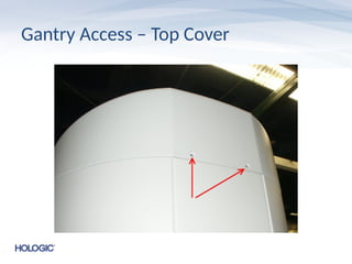
Gantry Access -Side Panels
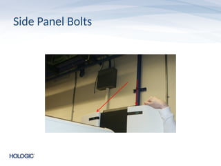
• The gantry side panels can be removed by first
unbolting the two top bolts
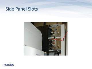
• The panels can be shifted to service location
by lifting out of their slotted position and
moving the inner tabs of the panel to rest in
the outer slots of the gantry
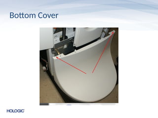
Bottom Cover
• Thebottom cover is slotted into the base and
held down with two allen screws at the top
• Can only be removed after the side panels
have been moved to the service location
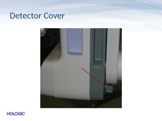
Detector Cover
• Thedetector cover is secured by two captured
allen screws at the back of the C-Arm
• The cover slides forward after the screwes
have been released
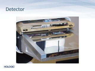
Detector
• The detectorhas 6 screws
– 4 on the bottom and 2 on the sides
– 2 on front bottom are shoulder screws and use a
different size t-handle than the other 4
– 2 in back bottom must have air vent removed to
accesss
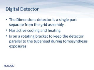
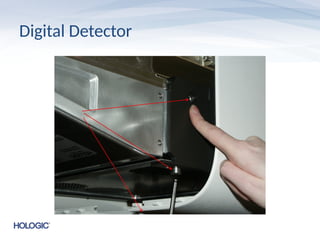
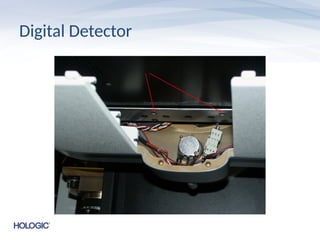
Digital Detector
• TheDimensions detector is a single part
separate from the grid assembly
• Has active cooling and heating
• Is on a rotating bracket to keep the detector
parallel to the tubehead during tomosynthesis
exposures
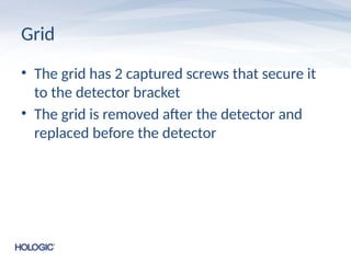
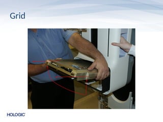
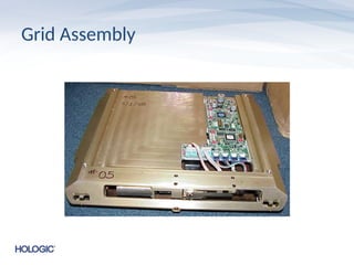
Grid Assembly
• Thegrid assembly is a single part unit that is
separate from the detector
• There are two versions of grid in the field
(though only one is prominent) and some may
require special settings in caltool
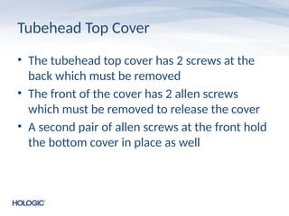
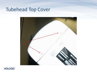
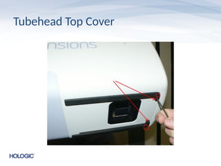
Tubehead Top Cover
•The tubehead top cover has 2 screws at the
back which must be removed
• The front of the cover has 2 allen screws
which must be removed to release the cover
• A second pair of allen screws at the front hold
the bottom cover in place as well
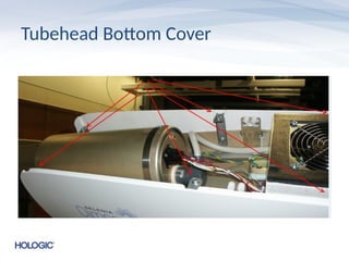
Tubehead Bottom Cover
•The front allen screws must be removed to
release the bottom tubehead cover
• Additionally there are 6 tabbed screws on the
top of the cover that must be loosened to
remove it
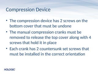
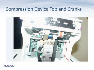
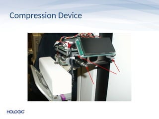
Compression Device
• Thecompression device has 2 screws on the
bottom cover that must be undone
• The manual compression cranks must be
removed to release the top cover along with 4
screws that hold it in place
• Each crank has 2 countersunk set screws that
must be installed in the correct orientation
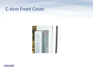
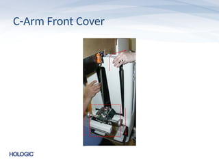
C-Arm Front Cover
•Two captured screws must be loosened from
the back of the C-Arm to release the front
cover. It will be necessary to rotate the C-Arm
to the side to release the screws
• The compression device should be ppushed all
the way down to release the front C-Arm
cover
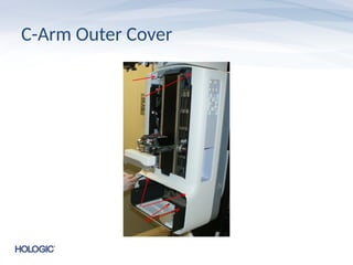
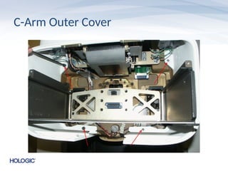
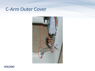
C-Arm Outer Cover
•After removing the front plate the outer cover
can be removed by unscrewing 4 screws at the
bottom and 2 captured screws at the top
• The switch panel cabling must be
disconnected to remove the outer cover
• This may include cabling for the Affirm device
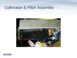
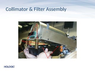
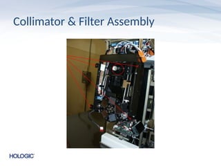
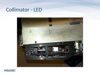
Collimator & FilterAssembly
• The collimator dust cover must be removed to
access the collimator and filter wheel assembly
• It is a good idea to mark the location of the
collimator bracket with a marker before
removal
• Remove the front tubehead cover bracket to
avoid damaging the filter wheel during removal
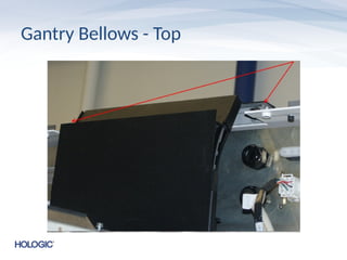
Gantry Bellows
• Thegantry bellows are attached to the top
and bottom of the gantry by two allen screws
each
• The screws should be removed and the
bellows can be rotated out of the way in order
to access the component drawers
• The service manual suggests disassembling
the bellows which takes significantly longer
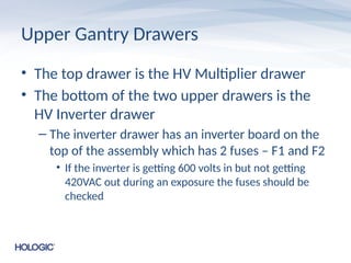
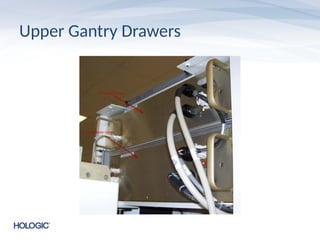
Upper Gantry Drawers
•The top drawer is the HV Multiplier drawer
• The bottom of the two upper drawers is the
HV Inverter drawer
– The inverter drawer has an inverter board on the
top of the assembly which has 2 fuses – F1 and F2
• If the inverter is getting 600 volts in but not getting
420VAC out during an exposure the fuses should be
checked
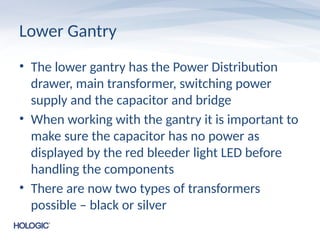
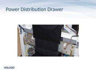
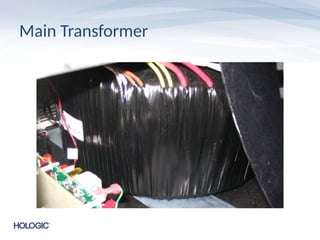
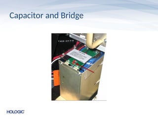
Lower Gantry
• Thelower gantry has the Power Distribution
drawer, main transformer, switching power
supply and the capacitor and bridge
• When working with the gantry it is important to
make sure the capacitor has no power as
displayed by the red bleeder light LED before
handling the components
• There are now two types of transformers
possible – black or silver
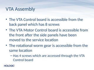
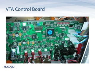
VTA Assembly
• TheVTA Control board is accessible from the
back panel which has 8 screws
• The VTA Motor Control board is accessible from
the front after the side panels have been
moved to the service location
• The rotational worm gear is accessible from the
same location
– Has 4 screws which are accessed through the VTA
Control board
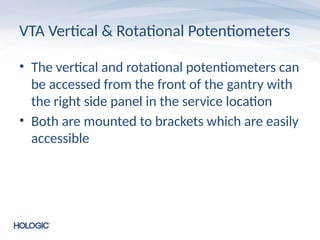
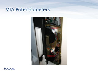
VTA Vertical &Rotational Potentiometers
• The vertical and rotational potentiometers can
be accessed from the front of the gantry with
the right side panel in the service location
• Both are mounted to brackets which are easily
accessible
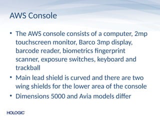
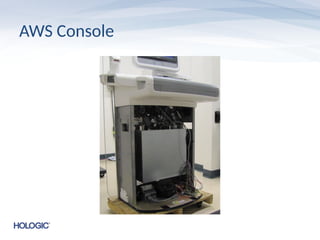
AWS Console
• TheAWS console consists of a computer, 2mp
touchscreen monitor, Barco 3mp display,
barcode reader, biometrics fingerprint
scanner, exposure switches, keyboard and
trackball
• Main lead shield is curved and there are two
wing shields for the lower area of the console
• Dimensions 5000 and Avia models differ
AWS Computer
• Thereare 3 varieties of AWS computer
currently available
• Older systems may have a Rev 5 computer
• Newer systems may have a Rev 6 or Rev 7
computer
59.
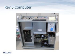
Rev 5 Computer
•Rev 5 computers have an internal DVD drive
• Two hard drives are installed in a RAID 1
configuration
• If the system came with a Rev 5 computer a
Rev 6 may be a paid upgrade
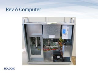
Rev 6 Computer
•Rev 6 computers removed the internal DVD
drive and the extra hard drive
• Rev 6 computers have a newer motherboard
with more USB ports on it
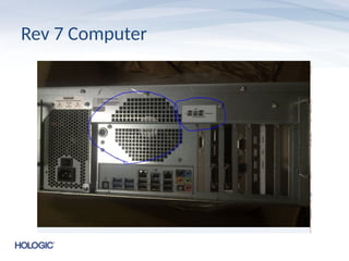
Rev 7 Computer
•The Rev 7 computer replaces the
motherboard of the Rev 6
• It has a 2 slot wide GTX680 video card
installed
• Has a single fan where the Rev 6 has 2
• A Rev 7 computer may be a paid upgrade from
previous revisions
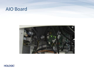
AIO Board
• Thereare 2 available AIO boards currently
– Original 5V version
– Newer 12V version
• The 12V version was developed to address issues with
early termination of exposure switches that may be
experienced at some sites
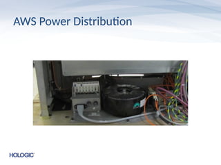
AWS Power Distribution
•The AWS Power Distribution is easily
accessible with the front cover of the console
removed
• The UPS is secured behind the computer
which would have to be removed first to
access it