CBD Belapur Individual Call Girls In 08976425520 Panvel Only Genuine Call Girls
Ly thuyet ALD_Geo 5.pdf
1. 03/03/2022 1
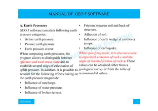
A. Earth Pressures
GEO 5 software considers following earth
pressure categories:
• Active earth pressure
• Passive earth pressure
• Earth pressure at rest
When computing earth pressures, the
program allows to distinguish between
effective and total stress state and to
establish several ways of calculation of
uplift pressure. In addition, it is possible to
account for the following effects having on
the earth pressure magnitude:
• Influence of surcharge.
• Influence of water pressure.
• Influence of broken terrain.
• Friction between soil and back of
structure.
• Adhesion of soil.
• Influence of earth wedge at cantilever
jumps.
• Influence of earthquake.
When specifying rocks, it is also necessary
to input both cohesion of rock c and the
angle of internal friction of rock These
values can be obtained either from a
geological survey or from the table of
recommended values.
MANUAL OF GEO 5 SOFTWARE
2. 03/03/2022 2
• Inclination of the ground surface β is positive, when the ground rises upwards from
the wall.
• Inclination of the back of structure α is positive, when the toe of the wall (at the
back face) is placed in the direction of the soil body when measured from the
vertical line constructed from the upper point of the structure.
• Friction between the soil and back of structure δ is positive, if the resultant of earth
pressure (thus also earth pressure) and normal to the back of structure form an
angle measured in the clockwise direction.
MANUAL OF GEO 5 SOFTWARE
3. 03/03/2022 3
I. Active Earth Pressure
Active earth pressure is the smallest limiting lateral pressure developed at the onset of
shear failure by wall moving away from the soil in the direction of the acting earth
pressure (minimal wall rotation necessary for the evoluation of the active earth
pressure is about 2mrad, i.e 2mm/m of the wall height (H/500)).
1. The Mazindrani Theory (Rankine)
Active earth pressure is given by the following formula:
Where:
z – vertical geostatic stress
Ka – coefficient of active earth pressure due to Rankine
– slope inclination
– weight of soil
z – assumed depth
MANUAL OF GEO 5 SOFTWARE
4. 03/03/2022 4
K’a – coefficient of active earth pressure due to Mazindrani
Where:
– slope inclination
– angle of internal friction of soil
c – cohesion of soil
Assuming cohesion-less soils (c = 0) and horizontal ground surface ( =0) yields the
Rankine solution, for which the active earth pressure is provided by
MANUAL OF GEO 5 SOFTWARE
5. 03/03/2022 5
2. The Coulomb Theory
Active earth pressure is given by the following formula
Where:
z – vertical geostatic stress
cef – effective cohesion of soil
Ka – coefficient of active earth pressure
Kac – coefficient of active earth pressure due to cohesion
MANUAL OF GEO 5 SOFTWARE
6. 03/03/2022 6
The coefficient of earth pressure Ka is given by:
The coefficient of active earth pressure Kac is given by
for < /4
for ≥ /4
Where:
– angle of internal friction of soil
δ – angle of friction between structure and soil
MANUAL OF GEO 5 SOFTWARE
7. 03/03/2022 7
Where:
– slope inclination
α – back face inclination of the structure.
Horizontal and vertical components of the active earth pressure become:
Where:
a – active earth pressure
δ – angle of friction between structure and soil
α – back face inclination of the structure
MANUAL OF GEO 5 SOFTWARE
8. 03/03/2022 8
4. The Caquot Theory
Active earth pressure is given by the following formula
Where:
z – vertical geostatic stress
cef – effective cohesion of soil
Ka – coefficient of active earth pressure
Kac – coefficient of active earth pressure due to cohesion
MANUAL OF GEO 5 SOFTWARE
9. 03/03/2022 9
The following analytical solution (Boussinessque, Caquot) is implemented to compute
the coefficient of active earth pressure Ka:
Where:
Ka – coefficient of active earth pressure due to Caquot
Ka
Coulomb - coefficient of active earth pressure due to Coulomb
conversion coefficient – see further
Where:
– slope inclination behind the structure
φ – angle of internal friction of soil
δ – angle of friction between structure and soil.
MANUAL OF GEO 5 SOFTWARE
1/sin
10. 03/03/2022 10
The coefficient of active earth pressure Kac is given by
for: < /4
for : >= /4
Where:
– angle of internal friction of soil
δ – angle of friction between structure and soil
β – slope inclination behind the structure
– back face inclination of the structure
MANUAL OF GEO 5 SOFTWARE
11. 03/03/2022 11
The horizontal and vertical components of the active earth pressure become:
Where:
a – angle earth pressure
δ – angle of friction between structure and soil
– back face inclination of the structure
MANUAL OF GEO 5 SOFTWARE
12. 03/03/2022 12
6. Total stress
When determining the active earth pressure in cohesive fully saturated soils, in which
case the consolidation is usually prevented (undrained conditions), the horizontal
normal total stress x receives the form
MANUAL OF GEO 5 SOFTWARE
13. 03/03/2022 13
Where:
x – horizontal total stress (normal)
z – vertical normal total stress
Kuc – coefficient of earth pressure
cu - total cohesion of soil
The coefficient of earth pressure Kuc is given by
Where:
Kuc – coefficient of earth pressure
cu - total cohesion of soil
au - total adhesion of soil to the structure
MANUAL OF GEO 5 SOFTWARE
14. 03/03/2022 14
II. Passive Earth Pressure
Passive earth pressure is the highest limiting lateral pressure developed at the onset of
shear failure by wall moving (penetrating) in the direction opposite to the direction of
acting earth pressure (minimal wall rotation necessary for the evolution of passive
earth pressure is about 10mrad, i.e. 10mm/m of the wall height). In most expressions
used to compute the passive earth pressure the sign convertion is assumed such that the
usual values of δ corresponding to vertical direction of the friction resultant are
negative.
1. Passive Earth Pressure – The Rankine and Mazindrani Theory
Passive earth pressure follows from the following formula
Where:
z – vertical geostatic stress
Kp - coefficient of passive earth due to Rankine
- slope inclination
MANUAL OF GEO 5 SOFTWARE
15. 03/03/2022 15
Where:
– weight of soil
z - assumed depth
K’p - coefficient of passive earth pressure due to Mazindrani.
The coefficient of passive earth pressure Kp is given by:
Where:
– slope inclination
- angle of internal friction of soil
c – cohesion of soil
MANUAL OF GEO 5 SOFTWARE
16. 03/03/2022 16
If there is no friction ( between the structure and cohesion-less soils (c = 0), the
ground surface is horizontal ( =0) and the resulting slip surface is also plane with the
slope:
The Mazindrani theory then reduces to the Rankine theory. The coefficient of passive
earth pressure is then provided by:
Where:
angle of internal friction of soil.
Passive earth pressure p by Rankine for cohesion-less soil is given:
Where:
unit weight of soil.
z – assumed depth
MANUAL OF GEO 5 SOFTWARE
17. 03/03/2022 17
Where:
Kp coefficient of passive earth pressure due to Rankine.
2. The Coulomb Theory
Passive earth pressure follows from the following formula:
Where:
z- effective vertical geostatic stress
Kp – coefficient of passive earth pressure due to Coulomb.
c – cohesion of soil.
The coefficient of passive earth pressure Kp is given by:
MANUAL OF GEO 5 SOFTWARE
18. 03/03/2022 18
Where:
– angle of internal friction of soil
– angle of friction between structure and soil
– slope inclination.
– back face inclination of the structure.
The vertical pv and horizontal ph components of passive earth pressure are given by:
Where:
- angle of friction between structure and soil.
– back face inclination of the structure
3. Passive Earth Pressure – The Caquot – Kerisel Theory
Passive earth pressure follows from the following formula:
MANUAL OF GEO 5 SOFTWARE
19. 03/03/2022 19
Where:
Kp – coefficient of passive earth pressure for , see the table.
– reduction coefficient for < see the table.
c – cohesion of soil.
z - vertical geostatic stress.
The vertical pv and horizontal ph component of passive earth pressure are given by:
Where:
– angle of friction between structure and soil.
– back face inclination of the structure
MANUAL OF GEO 5 SOFTWARE
21. 03/03/2022 21
7. Passive Earth Pressure – Total Stress
When determining the passive earth pressure in cohesive fully saturated soils, in which
case the consolidation is usually prevented (undrained conditions), the horizontal
normal total stress z receives the form:
Where:
x- horizontal total stress (normal)
z- vertical normal total stress (normal)
Kuc – coefficient of earth pressure.
cu – total cohesion of soil.
The coefficient of earth pressure Kuc is given by:
MANUAL OF GEO 5 SOFTWARE
Where:
au – total adhesion of soil to the structure
22. 03/03/2022 22
Deep Excavation – Theory and Practice – Chang Yu Ou
1. General discussion of various earth pressure theories
- According to the loading conditions of soil, when the soil’s strained state changes
from Ko to active failure, the direction of its principal stresses will remain
unchanged.
- From Ko to passive failure, its direction will change by a rotation of 90o. That is 1
is originally vertical (1 = v) and then changes to be horizontal (1 = h). Both the
major and minor principal stresses rotate by 90o. Thus, the strain for soil to come
to passive failure is greater than that for it to reach active failure.
- The necessary wall displacement inducing passive conditions for cohesionless soils
is four times larger than that inducing active conditions. For cohesive soils, the
relationship is about two times.
MANUAL OF GEO 5 SOFTWARE
24. 03/03/2022 24
MANUAL OF GEO 5 SOFTWARE
- Rankine’s earth pressure theory is based on the principle of the plasticity
equilibrium of the strained soil. That is to say, soil at any point within the failure
zone (also called the wedge) is indiscriminately at failure and thereby there are
infinite failure surfaces.
- Coulom’s theory is derived according to the principle of force equilibrium. As a
result, there is only one failure surface, which is a plane, assuming that the wedge
between the failure surface and the retaining wall is rigid.
- For problems of excavation, considering that the active earthe pressure is usually
the main force leading to the failure of retaining walls, Caquot- Kerisel’s active
earth pressure should be adopted for analysis and design since it is regarded as
most the same under most circumstances, Coulomb’s coefficient of active earth
pressure is also workable for analysis and design. For conservative reasons,
Rankine’s coefficient of active earth pressure is recommended for it is the largest
among the three without significant difference from Caquot- Kerisels’s.
- The passive earth pressure is usually the force resisting failure. Caquot- Kerisel’s
passive earth pressure is regarded as the real passive earth pressure and is
therefore the most favored choice.
25. 03/03/2022 25
MANUAL OF GEO 5 SOFTWARE
- .
Coefficients of Rankine’s Coulomb’s, and Caquot – Kerisel’s active earth pressure
(horizontal component Ka,h = Kacos
26. 03/03/2022 26
MANUAL OF GEO 5 SOFTWARE
- .
Coefficients of Rankine’s Coulomb’s, and Caquot – Kerisel’s passive earth pressure
(horizontal component Kp,h = Kpcos
27. 03/03/2022 27
III. Earth Pressure at Rest
Earth pressure at rest, is the horizontal pressure acting on the rigid structure. It is
usually assumed in cases, when it is necessary to minimize the lateral and horizontal
deformation of the sheeted soil (e.g. when laterally supporting a structure in the
excavation pit up to depth below the current foundation or in general when casing soil
with structures sensitive to non-uniform settlement), or when structures loaded by earth
pressures are due to some technological reasons extremely rigid and do not allow for
deformation in the direction of load necessary to mobilize the active earth pressure.
Earth pressure at rest is given by:
MANUAL OF GEO 5 SOFTWARE
28. 03/03/2022 28
For cohesive soils the Terzaghi formula for computing Kr is implemented in the
program:
Kr = /(1 - )
Where:
– poisson’s ratio
For cohesionless soils, the Jaky’s expression is used:
Kr = 1- sin
Where:
– angle of internal friction of soil
When computing the pressure at rest for cohesive soil r using Jaky’s formula for the
determination of coefficient of earth pressure at rest Kr , it is re-commended to use the
alternate angle of internal friction n. The way of computing the earth pressure at rest
can be therefore influenced by the selection of the type of soil (cohesive, cohesionless)
when inputting its parameters. Even typically cohesionless soil (sand, gravel) must be
introduced as cohesive if we wish to compute the pressure at rest with the help of the
MANUAL OF GEO 5 SOFTWARE
29. 03/03/2022 29
Poisson ratio and vice versa.
For over-consolidated soils, the expression proposed by Schmertmann to compute the
coefficient of earth pressure at rest Kr is used:
Kr = 0.5(OCR)0.5
Where:
Kr – coefficient of earth pressure at rest.
OCR – over-consolidated ratio.
Earth Pressure at Rest for an Inclined Ground Surface or Inclined back of the
Structure.
For inclined ground surface behind the structure (0o ≤ ≤ ) the earth pressure at rest
assumes the form:
MANUAL OF GEO 5 SOFTWARE
30. 03/03/2022 30
Where:
- angle of internal friction of soil.
– slope inclination
z – vertical geostatic stress
Kr – coefficient of earth pressure at rest
For inclined back of wall the values of earth pressure at rest are derived from:
Where:
- back face inclination of the structure
z– vertical geostatic stress
Kr – coefficient of earth pressure at rest
Normal and tangential components are given by:
MANUAL OF GEO 5 SOFTWARE
31. 03/03/2022 31
Where:
- back face inclination of the structure
z – vertical geostatic stress
Kr – coefficient of earth pressure at rest
The deviation angle from the normal line to the wall reads:
Where:
- back face inclination of the structure
Kr – coefficient of earth pressure at rest
Increased Active Pressure
The increased active pressure is calculated using k coefficient.
The magnitude of the pressure is calculated by the formula:
MANUAL OF GEO 5 SOFTWARE
32. 03/03/2022 32
Where:
r – pressure at rest.
a – active earth pressure
k– coefficient of increased active pressure.
If the values of coefficient k = 1, then the acting pressure is equal to pressure at rest. If
the value of coefficient k = 0, then the acting pressure is equal to the active pressure.
B. The influence of ground water
1. Without Ground Water, Water is not considered
In this option the influence of ground water is not considered.
Complementary information:
If there are fine soils at and below the level of GWT, one should carefully assess an
influence of full saturation in the region of capillary attraction. The capillary attraction
is in the analysis reflected only by increased degree of saturation, and therefore the
value of sat is inserted into parameters of soils.
MANUAL OF GEO 5 SOFTWARE
33. 03/03/2022 33
To distinguish regions with different degree of saturation, one may insert several layers
of the same soil with different unit weight. Negative pore pressures are not considered.
However, for layers with different degree of saturation it is possible to use different
values of shear resistance influenced by suction (difference in pore pressure of water
and gas (ua – uw).
2. Hydrostatic pressure, ground water behind the structure.
The heel of a structure is sunk into impermeable subsoil so that the water flow
below the structure is prevented. Water is found behind the back of structure only.
There is no water acting on the front face. Such a case may occur when water in front
of structure flow freely due to gravity or deep drainage is used. The back of structure is
loaded by the hydrostatic pressure:
Where:
w – unit weight of water
hw– water tables difference.
MANUAL OF GEO 5 SOFTWARE
34. 03/03/2022 34
3. Hydrostatic pressure, ground water behind and in front of the structure.
The heel of a structure is sunk into impermeable subsoil so that the water flow
below the structure is prevented. The load due water is assumed both in front of and
behind the structure. The water in front of structure is removed either with the help of
gravity effects or is shallowly lowered by pumping. Both the face and back of structure
is loaded by hydrostatic pressure due to difference in water tables (h1 and h2). The
dimension hw represents the difference in water tables at the back and in front of
structure –see figure:
MANUAL OF GEO 5 SOFTWARE
35. 03/03/2022 35
4. Hydrodynamic pressure
The heel of a structure is sunk into permeable subsoil, which allows free water
flow below the structure – see figure. The unit weight of soil lifted by uplift pressure su
is modified to account for flow pressure. These modifications then depend on the
direction of water flow.
MANUAL OF GEO 5 SOFTWARE
36. 03/03/2022 36
When computing the earth pressure in the area of descending flow the program
introduces the following value of the unit weight of soil:
= su + = su + i.w
and in the area of ascending flow the following value:
Where:
su – unit weight of submerged soil
– alteration of unit weight of soil.
i – an average seepage gradient.
w – unit weight of water.
MANUAL OF GEO 5 SOFTWARE
37. 03/03/2022 37
An average hydraulic slope is given:
i = hw/(dd +du)
Where:
i – an average seepage gradient.
hw – water table difference
dd – seepage path downwards
du – seepage path upwards
If the change of unit weight of soil provided by:
= i . w
Is greater than the unit weight of saturated soil su, then the leaching appears in front of
structure - as a consequence of water flow the soil behaves as weightless and thus
cannot transmit any load. The program then prompts a warning message and further
assumes the value of =0. The result therefore no longer corresponds to the original
input – is safer.
MANUAL OF GEO 5 SOFTWARE
38. 03/03/2022 38
5. Special Distribution of Water pressure
This option allows an independent (manual) input of distribution of load due to
water at the back and in front of structure using ordinates of pore pressure at different
depths. The variation of pressure between individual values is linear. At the same time
it is necessary to input levels of tables of full saturation of a soil at the back h1 and in
front h2 of structure including possible decrease of unit weight y in front of structure
due to water flow.
The variation of pore pressure above the clay layer is driven by free ground water table
GWT1. The distribution of pore pressure below the clay layer results from ratio in the
lower separated ground water table GWT2, where the ground water is stressed. The
pore pressure distribution in clay is approximately linear.
MANUAL OF GEO 5 SOFTWARE
40. 03/03/2022 40
C. Sheeting Check
The program verifies the input structure using the method of dependent pressure or
using the spring method according to JGJ 120-2012. The load applied to the structure
is derived from its deformation, which allows to realistically model its behavior and
provides cost effective designs. The analysis correctly accounts for the construction
process such as individual stages of progressive construction of the wall (stages of
constructions) including gradual evolution of deformations and post- stressing of
anchors. Program can model any kind of braced sheeting too.
The use of the method of dependent pressure requires determination of the modulus of
subsoil reaction, which is assumed either linear or nonlinear.
The program also allows the user to check internal stability of the anchorage system.
The actual analysis is carried out using the deformation variant of the finite element
method. Displacements, internal forces and the modulus of subsoil reaction are
evaluated at individual nodes.
The following procedure for dividing the structure into finite elements is assumed:
MANUAL OF GEO 5 SOFTWARE
41. 03/03/2022 41
• First, the nodes are inserted into all topological points of a structure (starting and
end points, points of location of anchor, points of soil removal, points of changes of
cross-sectional parameters).
• Based on selected subdivision, the program computes the remaining nodes such
that all elements attain approximately the same size.
A value of the modulus of subsoil reaction is assigned to each element – it is
considered as the Winkler spring of the elastic subsoil. Supports are placed onto
already deformed structure- each support then represents a forced displacement applied
to the structure.
In the construction stage, where are introduce, pre-stressed anchors are modeled as
force (variant I in Fig). In other construction stages the anchors are modeled springs of
stiffness k (variant II. In Fig) and force.
MANUAL OF GEO 5 SOFTWARE
42. 03/03/2022 42
I. Method of Dependent Pressures
The basic assumption of the method is that the soil or rock in the vincinity of wall
behaves as ideally elastic-plastic Winkler material. This material is determined by the
modulus of subsoil reaction kh, which characterizes the deformations in the plastic
region and by additional limiting deformations. When exceeding these deformations the
material behaves as ideally plastic.
The following assumptions are used:
• The pressure acting on a wall may attain an arbitrary value between active and
passive pressure – but it cannot fall outside of these boundaries.
• The pressure at rest acts on an undeformed structure (w= 0)
The pressure acting on a deformed structure is given by:
= r – khw
=a for < a
=p for > p
MANUAL OF GEO 5 SOFTWARE
43. 03/03/2022 43
Where:
r – pressure at rest
kh – modulus of subsoil reaction
w – deformation of structure
a – active earth pressure
p – passive earth pressure
The computational procedure is as follows:
• The modulus of subsoil reaction kh is assigned to all elements and the structure is
loaded by the pressure at rest – see figure:
• The analysis is carried out and the condition for allowable magnitudes of pressures
acting on the wall is checked. In locations at which these conditions are violated the
program assigns the value of kh = 0 and the wall is loaded by active or passive
pressure, respectively – see figure:
MANUAL OF GEO 5 SOFTWARE
44. 03/03/2022 44
• The above iteration procedure continues until all required conditions are satisfied.
In analyses of subsequent stages of construction the program accounts for plastic
deformation of the wall. This is also the reason for specifying individual stages of
construction that comply with the actual construction process.
II. Spring Method According to JGJ 120-2012
This method is used for analysis of sheeting structures and it is based on the Chinese
standard JGJ 120-2012 (Technical specification for retaining and protection of building
foundation excavation). In principle, this theory is similar to calculation according to
the method of dependent pressure, the difference is in consideration of earth pressure.
The following figure show that behind the wall (outside of the foundation pit) acts
active earth pressure pa or earth pressure at rest po (it’s defined in the “Settings”
frame).
In front of the wall there are considered springs (defined by using the modulus of
subsoil reaction), which models reaction of the soil in a horizontal direction. In case of
the attainment of ultimate pressures a limiting of the size of springs is the same as for
method of dependent pressures.
MANUAL OF GEO 5 SOFTWARE