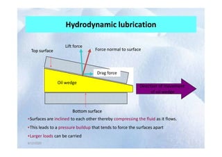
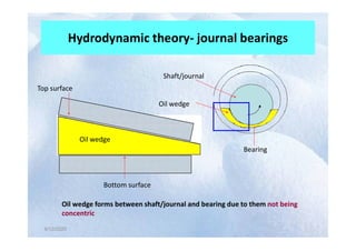
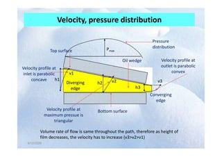
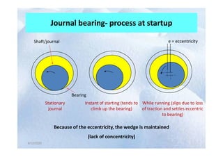
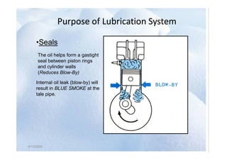
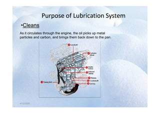
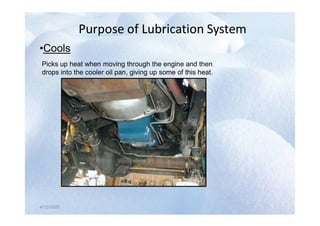
Wear Analysis & Control
UNIT III: “LUbrIcaTION”
Lecture by
Dr. Mukund Dutt Sharma
Assistant Professor
Mechanical Engineering Department
National Institute of Technology
Srinagar – 190 006 (J.K.) India
E-Mail: mukund.sharma@nitsri.net
Website: http//nitsri.ac.in/
Contents
• Lubrication
• Lubrication Regimes
• Hydrodynamic and Hydrostatic Lubrication
• Theory of Lubrication
• Lubrication system
4/12/2020
NATIONAL INSTITUTE OF
TECHNOLOGY, SRINAGAR, J & K,
INDIA
Lubrication
INTRODUCTION
• The object of lubrication is to reduce friction, wear, and heating of
machine parts that move relative to each other.
• A lubricant is any substance that, when inserted between the
moving surfaces accomplishes these purposes.
• In a sleeve bearing a shaft, or journal rotates oscillates within a
4/12/2020
• In a sleeve bearing a shaft, or journal rotates oscillates within a
sleeve, or bushing and the relative motion is sliding.
• In an antifriction bearing, the main relative motion is rolling.
• A follower may either roll or slide on the cam. Gear teeth mate with
each other by a combination of rolling or sliding. Piston slides within
their cylinders. All these application require lubrication to reduce
friction, wear and heating.
NATIONAL INSTITUTE OF
TECHNOLOGY, SRINAGAR, J & K,
INDIA
Hydrodynamic and Hydrostatic Lubrication
 Hydrodynamic Lubrication :- Formed the oil film by the relative movement of
the friction surface.
 Hydrostatic Lubrication :- Formed the oil film on the friction surface by the
external pressure oil.
Hydrodynamic lubrication means that the load carrying surfaces of the bearing
are separated by a relatively thick film of the lubricant, so as to prevent metal to
4/12/2020 4
are separated by a relatively thick film of the lubricant, so as to prevent metal to
metal contact, and that the stability thus obtained can be explained by the laws
of fluid mechanics .
Hydrodynamic lubrication also called full film or fluid lubrication.
Hydrostatic lubrication is also obtained by introducing the lubricant, which is
sometimes air or water, into the load bearing area at a pressure high enough to
separate the surfaces with a relatively thick film of lubricant. So, unlike
Hydrodynamic lubrication, the kind of lubrication does not require motion of one
surface relative to other.
NATIONAL INSTITUTE OF
TECHNOLOGY, SRINAGAR, J & K,
INDIA
Lubrication Regimes
Lubrication Regimes
• Sliding friction is significantly reduced by an addition of a lubricant between
the rubbing surfaces.
• Engine bearings are lubricated by Engine oils constantly supplied in
sufficient amounts to the bearings surfaces.
• Lubricated friction is characterized by the presence of a thin film of the
4/12/2020
• Lubricated friction is characterized by the presence of a thin film of the
pressurized lubricant (squeeze film) between the surfaces of the bearing
and the journal.
• The ratio of the squeeze film (oil film) thickness h to the surface
roughness Ra determines the type of the lubrication regime:
4/12/2020
Boundary lubrication (h<Ra)
 A constant contact between the friction surfaces at high surface points
(microasperities) occurs at boundary lubrication.
 This regime is the most undesirable since it is characterized by high
coefficient of friction (energy loss), increased wear, possibility of seizure
between the bearing and journal materials , non-uniform distribution of the
bearing load (localized pressure peaks).
4/12/2020
 Very severe engine bearing failures are caused by boundary lubrication.
 Conditions for boundary lubrication are realized mainly at low speed friction
(engine start and shutdown) and high loads.
 Extreme pressure (EP) additives in the lubricant prevent seizure conditions
caused by direct metal-to-metal contact between the parts in the
boundary lubrication regime.
4/12/2020
Mixed lubrication (h~Ra)
 An intermittent contact between the friction surfaces at few high surface
points (microasperities) occurs at mixed lubrication.
 Mixed lubrication is the intermediate regime between
boundary lubrication and hydrodynamic friction.
4/12/2020
4/12/2020
Hydrodynamic lubrication (h»Ra)
• High rotation speed at relatively low bearing loads results in hydrodynamic
friction, which is characterized by stable squeeze film (oil film) between the
rubbing surfaces.
• No contact between the surfaces occurs in hydrodynamic lubrication.
• The squeeze film keeps the surfaces of the bearing and the shaft apart due
to the force called hydrodynamic lift generated by the lubricant squeezed
4/12/2020
to the force called hydrodynamic lift generated by the lubricant squeezed
through the convergent gap between the eccentric journal and bearing.
• Bearings working under the conditions of hydrodynamic lubrication are
called hydrodynamic journal bearings.
4/12/2020
4/12/2020
4/12/2020
The three lubrication regimes are clearly distinguished in the Striebeck curve
(see the figure above), which demonstrates the relationship between the
coefficient of friction and the bearing parameter η*N/pav (η - dynamic viscosity
of the lubricant, N - rotation speed, pav - average bearing pressure).
Stability of different lubrication regimes may be explained by means of the
Striebeck curve:
Temperature increase due to heat generated by friction causes drop of the
lubricant viscosity and the bearing parameter.
4/12/2020
According to the Striebeck curve decrease of the bearing parameter in mixed
regime causes increase of the coefficient of friction followed by further
temperature rise and consequent increase of the coefficient of friction.
Thus mixed lubrication is unstable.
Increase of the bearing parameter due to temperature rise (lower viscosity) in
hydrodynamic regime of lubrication causes the coefficient of friction to drop with
consequent decrease of the temperature. The system corrects itself.
Thus hydrodynamic lubrication is stable.
4/12/2020
Hydrodynamic Lubrication
A theoretical analysis of hydrodynamic lubrication was carried out by Osborne Reynolds.
The equations resulted from the analysis has served a basis for
designing hydrodynamically lubricated bearings.
The following assumptions were made by Reynolds in the analysis:
The lubricating fluid is Newtonian - the flow is laminar and the shear stress between the
flow layers is proportional to the velocity gradient in the direction perpendicular to the flow
(Newton’s law of viscosity):
Where:
4/12/2020
Where:
η – dynamic viscosity of oil,
v – linear velocity of the laminar layer,
y - the axis perpendicular to the flow direction.
The inertia forces resulted from from the accelerated movement of the flowing lubricant
are neglected.
The lubricating fluid is incompressible.
The pressure of the fluid p is constant in the direction perpendicular to the laminar
flow: dp/dy=0 (assumption of thin lubrication film).
The viscosity of the fluid is constant throughout the lubrication film.
Consider the equilibrium of a unit volume in the lubricant film.
4/12/2020
Hydrodynamic lubrication
• Also called fluid-film, thick-film, or flooded lubrication
• A thick film of lubricant is interposed between the surfaces
of bodies in relative motion
• There has to be pressure buildup in the film due to relative
motion of the surfaces
4/12/2020
4/12/2020
motion of the surfaces
• Fluid friction is substituted for sliding friction
• Coefficient of friction is decreased
• Prevalent in journal and thrust bearings
Parallel surfaces
Direction of motion
of top plate
Top layer of fluid moves with
same velocity as the plate
Velocity of top plate = u
y
Shear force F
Velocity profile
(same throughout)
4/12/2020
4/12/2020
Velocity of bottom plate = 0
A is area of the plate
(same throughout)
•There is no pressure buildup in the fluid due to relative motion
•It remains constant throughout influenced only by the load
•As load increases the surfaces are pushed towards each other until they
are likely to touch
Lubricant
Hydrodynamic lubrication
Lift force
Drag force
Force normal to surface
Top surface
Drag force
Top surface
4/12/2020
4/12/2020
Direction of movement
of oil wedge
Oil wedge
Bottom surface
Oil wedge
Bottom surface
•Surfaces are inclined to each other thereby compressing the fluid as it flows.
•This leads to a pressure buildup that tends to force the surfaces apart
•Larger loads can be carried
Hydrodynamic theory- journal bearings
Top surface
Shaft/journal
Oil wedge
4/12/2020
4/12/2020
Oil wedge
Bottom surface
Bearing
Oil wedge forms between shaft/journal and bearing due to them not being
concentric
Velocity, pressure distribution
Oil wedge
Top surface
h1 v2
v1
v3
Velocity profile at
inlet is parabolic
concave
Velocity profile at
outlet is parabolic
convex
Pmax
Pressure
distribution
4/12/2020
4/12/2020
Bottom surface
h1
h2
h3
v2 v3
Converging
edge
Diverging
edge
Volume rate of flow is same throughout the path, therefore as height of
film decreases, the velocity has to increase (v3>v2>v1)
concave
Velocity profile at
maximum pressue is
triangular
Journal bearing- process at startup
e = eccentricity
Shaft/journal
4/12/2020
4/12/2020
Stationary
journal
Instant of starting (tends to
climb up the bearing)
While running (slips due to loss
of traction and settles eccentric
to bearing)
Bearing
Because of the eccentricity, the wedge is maintained
(lack of concentricity)
Pressure distribution in a journal bearing
SHAFT
Shaft/journal
4/12/2020
4/12/2020
Pressure
distribution
Bearing
Max. pressure is reached somewhere in between the inlet and outlet
(close to outlet)
Tilting pad thrust bearings
Number of tilting pads
forming wedges
4/12/2020
4/12/2020
Axial
direction
Wedge
formation
Tilting pad thrust bearing
Collar
Pivot
Direction of
rotation
Bearing
plate
Propeller
4/12/2020
4/12/2020
Shaft
Tilting pad
Pivot
Axial loads from machinery being driven
In this case thrust from propeller
Oil wedge
•Back thrust from water to propeller causes
axial loading on the shaft
•Axial loads are opposed by pressure
buildup in the wedge
•Gives a damping effect
Hydrodynamic lubrication- characteristics
• Fluid film at the point of minimum thickness
decreases in thickness as the load increases
• Pressure within the fluid mass increases as the film
thickness decreases due to load
4/12/2020
4/12/2020
• Pressure within the fluid mass is greatest at some
point approaching minimum clearance and lowest
at the point of maximum clearance (due to
divergence)
• Viscosity increases as pressure increases (more
resistance to shear)
• Film thickness at the point of minimum clearance
increases with the use of more viscous fluids
• With same load, the pressure increases as the
viscosity of fluid increases
Hydrodynamic lubrication- characteristics
4/12/2020
4/12/2020
• With a given load and fluid, the thickness of the
film will increase as speed is increased
• Fluid friction increases as the viscosity of the
lubricant becomes greater
Hydrodynamic condition- Fluid velocity
• Fluid velocity depends on velocity of the
journal or rider
• Increase in relative velocity tends towards a
4/12/2020
4/12/2020
• Increase in relative velocity tends towards a
decrease in eccentricity of journal bearing
centers
• This is accompanied by greater minimum film
thickness
Hydrodynamic condition- Load
• Increase in load decreases minimum film thickness
• Also increases pressure within the film mass to
provide a counteracting force
4/12/2020
4/12/2020
• Pressure acts in all directions, hence it tends to
squeeze the oil out of the ends of the bearing
• Increase in pressure increases fluid viscosity
4/12/2020
Functions of lubricating oil
• Reduces friction between the moving parts
• Reduces wear of the moving parts as far as possible
• Acts like a cooling medium
Reduces noise between striking surfaces
4/12/2020
• Reduces noise between striking surfaces
• To provide sealing action
• To provide cushioning effect
• To provide cleaning action
4/12/2020
Requirements of lubricants
•Viscosity – high viscosity index (VI)
•Petroleum lube oils – VI - 100-100
•Can be increased to 120-130 by means of additives
•Physical stability
•Chemical stability
4/12/2020
•Resistance against corrosion
•Flash point – should be high
•Cleanliness
•Resistance against extreme pressure
4/12/2020
Types of lubricants
Types of lubricants
•Animal oils
•Vegetable oils
•Mineral oils
4/12/2020
•Synthetic lubricants
•Greases
•Solid lubricants – Graphite
4/12/2020
Viscosity rating
Viscosity rating
•According to The Society of Automotive Engineers (SAE)
•0W,5W,10W,20W,25W – for winter use
•10,15,20,30,40,50,60,80,100,150,200,300 – for summer use
•Multigrade oils – 10W/30
4/12/2020
4/12/2020
Oil additives
Oil additives
The chemical substances which are added to the lubricating oil
either to reinforce some of its natural properties or to provide
it with certain new properties which it does not possess
originally
 Oxidation inhibitors – amines, sulphides or phenols with
metals like tin, zinc or barium
 Corrosion inhibitors - oxidation inhibitors with metal salts
4/12/2020
 Detergents – high temperature deposits – gums and varnishes
and dispersants – low temp deposits – cold sludge
 Anti scuff additives - to polish moving parts like piston,
cylinder walls, cams etc.,
 Viscosity index improvers
 Anti foaming additives – polyorganosiloxanes
4/12/2020
Parts which require lubrication
•Main crankshaft bearing
•Big end bearings
•Gudgeon pin bearings
•Piston rings and cylinder walls
4/12/2020
•Piston rings and cylinder walls
•Timing gear
•Camshaft and camshaft bearings
•Valve mechanism
•Electrical equipment
4/12/2020
LUBRICATION SYSTEM
LUBRICATION SYSTEM
4/12/2020
4/12/2020
Purpose of Lubrication System
•Lubricate
Reduces Friction by creating a thin film(Clearance)
between moving parts (Bearings and journals)
4/12/2020
4/12/2020
Purpose of Lubrication System
•Seals
The oil helps form a gastight
seal between piston rings
and cylinder walls
(Reduces Blow-By)
Internal oil leak (blow-by) will
4/12/2020
4/12/2020
Internal oil leak (blow-by) will
result in BLUE SMOKE at the
tale pipe.
Purpose of Lubrication System
•Cleans
As it circulates through the engine, the oil picks up metal
particles and carbon, and brings them back down to the pan.
4/12/2020
4/12/2020
4/12/2020
Purpose of Lubrication System
•Cools
Picks up heat when moving through the engine and then
drops into the cooler oil pan, giving up some of this heat.
4/12/2020
4/12/2020
4/12/2020
Purpose of Lubrication System
•Absorbs shock
shock
When heavy loads are imposed on the bearings, the oil
helps to cushion the load.
•Absorbs Contaminants
4/12/2020
4/12/2020
4/12/2020
•Absorbs Contaminants
The additives in oil helps in absorbing the contaminants
that enter the lubrication system.
38 12 April 2020

Lubricants

  • 1.
    Wear Analysis &Control UNIT III: “LUbrIcaTION” Lecture by Dr. Mukund Dutt Sharma Assistant Professor Mechanical Engineering Department National Institute of Technology Srinagar – 190 006 (J.K.) India E-Mail: mukund.sharma@nitsri.net Website: http//nitsri.ac.in/
  • 2.
    Contents • Lubrication • LubricationRegimes • Hydrodynamic and Hydrostatic Lubrication • Theory of Lubrication • Lubrication system 4/12/2020 NATIONAL INSTITUTE OF TECHNOLOGY, SRINAGAR, J & K, INDIA
  • 3.
    Lubrication INTRODUCTION • The objectof lubrication is to reduce friction, wear, and heating of machine parts that move relative to each other. • A lubricant is any substance that, when inserted between the moving surfaces accomplishes these purposes. • In a sleeve bearing a shaft, or journal rotates oscillates within a 4/12/2020 • In a sleeve bearing a shaft, or journal rotates oscillates within a sleeve, or bushing and the relative motion is sliding. • In an antifriction bearing, the main relative motion is rolling. • A follower may either roll or slide on the cam. Gear teeth mate with each other by a combination of rolling or sliding. Piston slides within their cylinders. All these application require lubrication to reduce friction, wear and heating. NATIONAL INSTITUTE OF TECHNOLOGY, SRINAGAR, J & K, INDIA
  • 4.
    Hydrodynamic and HydrostaticLubrication Hydrodynamic and Hydrostatic Lubrication  Hydrodynamic Lubrication :- Formed the oil film by the relative movement of the friction surface.  Hydrostatic Lubrication :- Formed the oil film on the friction surface by the external pressure oil. Hydrodynamic lubrication means that the load carrying surfaces of the bearing are separated by a relatively thick film of the lubricant, so as to prevent metal to 4/12/2020 4 are separated by a relatively thick film of the lubricant, so as to prevent metal to metal contact, and that the stability thus obtained can be explained by the laws of fluid mechanics . Hydrodynamic lubrication also called full film or fluid lubrication. Hydrostatic lubrication is also obtained by introducing the lubricant, which is sometimes air or water, into the load bearing area at a pressure high enough to separate the surfaces with a relatively thick film of lubricant. So, unlike Hydrodynamic lubrication, the kind of lubrication does not require motion of one surface relative to other. NATIONAL INSTITUTE OF TECHNOLOGY, SRINAGAR, J & K, INDIA
  • 5.
    Lubrication Regimes Lubrication Regimes •Sliding friction is significantly reduced by an addition of a lubricant between the rubbing surfaces. • Engine bearings are lubricated by Engine oils constantly supplied in sufficient amounts to the bearings surfaces. • Lubricated friction is characterized by the presence of a thin film of the 4/12/2020 • Lubricated friction is characterized by the presence of a thin film of the pressurized lubricant (squeeze film) between the surfaces of the bearing and the journal. • The ratio of the squeeze film (oil film) thickness h to the surface roughness Ra determines the type of the lubrication regime: 4/12/2020
  • 6.
    Boundary lubrication (h<Ra) A constant contact between the friction surfaces at high surface points (microasperities) occurs at boundary lubrication.  This regime is the most undesirable since it is characterized by high coefficient of friction (energy loss), increased wear, possibility of seizure between the bearing and journal materials , non-uniform distribution of the bearing load (localized pressure peaks). 4/12/2020  Very severe engine bearing failures are caused by boundary lubrication.  Conditions for boundary lubrication are realized mainly at low speed friction (engine start and shutdown) and high loads.  Extreme pressure (EP) additives in the lubricant prevent seizure conditions caused by direct metal-to-metal contact between the parts in the boundary lubrication regime. 4/12/2020
  • 7.
    Mixed lubrication (h~Ra) An intermittent contact between the friction surfaces at few high surface points (microasperities) occurs at mixed lubrication.  Mixed lubrication is the intermediate regime between boundary lubrication and hydrodynamic friction. 4/12/2020 4/12/2020
  • 8.
    Hydrodynamic lubrication (h»Ra) •High rotation speed at relatively low bearing loads results in hydrodynamic friction, which is characterized by stable squeeze film (oil film) between the rubbing surfaces. • No contact between the surfaces occurs in hydrodynamic lubrication. • The squeeze film keeps the surfaces of the bearing and the shaft apart due to the force called hydrodynamic lift generated by the lubricant squeezed 4/12/2020 to the force called hydrodynamic lift generated by the lubricant squeezed through the convergent gap between the eccentric journal and bearing. • Bearings working under the conditions of hydrodynamic lubrication are called hydrodynamic journal bearings. 4/12/2020
  • 9.
  • 10.
    The three lubricationregimes are clearly distinguished in the Striebeck curve (see the figure above), which demonstrates the relationship between the coefficient of friction and the bearing parameter η*N/pav (η - dynamic viscosity of the lubricant, N - rotation speed, pav - average bearing pressure). Stability of different lubrication regimes may be explained by means of the Striebeck curve: Temperature increase due to heat generated by friction causes drop of the lubricant viscosity and the bearing parameter. 4/12/2020 According to the Striebeck curve decrease of the bearing parameter in mixed regime causes increase of the coefficient of friction followed by further temperature rise and consequent increase of the coefficient of friction. Thus mixed lubrication is unstable. Increase of the bearing parameter due to temperature rise (lower viscosity) in hydrodynamic regime of lubrication causes the coefficient of friction to drop with consequent decrease of the temperature. The system corrects itself. Thus hydrodynamic lubrication is stable. 4/12/2020
  • 11.
    Hydrodynamic Lubrication A theoreticalanalysis of hydrodynamic lubrication was carried out by Osborne Reynolds. The equations resulted from the analysis has served a basis for designing hydrodynamically lubricated bearings. The following assumptions were made by Reynolds in the analysis: The lubricating fluid is Newtonian - the flow is laminar and the shear stress between the flow layers is proportional to the velocity gradient in the direction perpendicular to the flow (Newton’s law of viscosity): Where: 4/12/2020 Where: η – dynamic viscosity of oil, v – linear velocity of the laminar layer, y - the axis perpendicular to the flow direction. The inertia forces resulted from from the accelerated movement of the flowing lubricant are neglected. The lubricating fluid is incompressible. The pressure of the fluid p is constant in the direction perpendicular to the laminar flow: dp/dy=0 (assumption of thin lubrication film). The viscosity of the fluid is constant throughout the lubrication film. Consider the equilibrium of a unit volume in the lubricant film. 4/12/2020
  • 12.
    Hydrodynamic lubrication • Alsocalled fluid-film, thick-film, or flooded lubrication • A thick film of lubricant is interposed between the surfaces of bodies in relative motion • There has to be pressure buildup in the film due to relative motion of the surfaces 4/12/2020 4/12/2020 motion of the surfaces • Fluid friction is substituted for sliding friction • Coefficient of friction is decreased • Prevalent in journal and thrust bearings
  • 13.
    Parallel surfaces Direction ofmotion of top plate Top layer of fluid moves with same velocity as the plate Velocity of top plate = u y Shear force F Velocity profile (same throughout) 4/12/2020 4/12/2020 Velocity of bottom plate = 0 A is area of the plate (same throughout) •There is no pressure buildup in the fluid due to relative motion •It remains constant throughout influenced only by the load •As load increases the surfaces are pushed towards each other until they are likely to touch Lubricant
  • 14.
    Hydrodynamic lubrication Lift force Dragforce Force normal to surface Top surface Drag force Top surface 4/12/2020 4/12/2020 Direction of movement of oil wedge Oil wedge Bottom surface Oil wedge Bottom surface •Surfaces are inclined to each other thereby compressing the fluid as it flows. •This leads to a pressure buildup that tends to force the surfaces apart •Larger loads can be carried
  • 15.
    Hydrodynamic theory- journalbearings Top surface Shaft/journal Oil wedge 4/12/2020 4/12/2020 Oil wedge Bottom surface Bearing Oil wedge forms between shaft/journal and bearing due to them not being concentric
  • 16.
    Velocity, pressure distribution Oilwedge Top surface h1 v2 v1 v3 Velocity profile at inlet is parabolic concave Velocity profile at outlet is parabolic convex Pmax Pressure distribution 4/12/2020 4/12/2020 Bottom surface h1 h2 h3 v2 v3 Converging edge Diverging edge Volume rate of flow is same throughout the path, therefore as height of film decreases, the velocity has to increase (v3>v2>v1) concave Velocity profile at maximum pressue is triangular
  • 17.
    Journal bearing- processat startup e = eccentricity Shaft/journal 4/12/2020 4/12/2020 Stationary journal Instant of starting (tends to climb up the bearing) While running (slips due to loss of traction and settles eccentric to bearing) Bearing Because of the eccentricity, the wedge is maintained (lack of concentricity)
  • 18.
    Pressure distribution ina journal bearing SHAFT Shaft/journal 4/12/2020 4/12/2020 Pressure distribution Bearing Max. pressure is reached somewhere in between the inlet and outlet (close to outlet)
  • 19.
    Tilting pad thrustbearings Number of tilting pads forming wedges 4/12/2020 4/12/2020 Axial direction Wedge formation
  • 20.
    Tilting pad thrustbearing Collar Pivot Direction of rotation Bearing plate Propeller 4/12/2020 4/12/2020 Shaft Tilting pad Pivot Axial loads from machinery being driven In this case thrust from propeller Oil wedge •Back thrust from water to propeller causes axial loading on the shaft •Axial loads are opposed by pressure buildup in the wedge •Gives a damping effect
  • 21.
    Hydrodynamic lubrication- characteristics •Fluid film at the point of minimum thickness decreases in thickness as the load increases • Pressure within the fluid mass increases as the film thickness decreases due to load 4/12/2020 4/12/2020 • Pressure within the fluid mass is greatest at some point approaching minimum clearance and lowest at the point of maximum clearance (due to divergence) • Viscosity increases as pressure increases (more resistance to shear)
  • 22.
    • Film thicknessat the point of minimum clearance increases with the use of more viscous fluids • With same load, the pressure increases as the viscosity of fluid increases Hydrodynamic lubrication- characteristics 4/12/2020 4/12/2020 • With a given load and fluid, the thickness of the film will increase as speed is increased • Fluid friction increases as the viscosity of the lubricant becomes greater
  • 23.
    Hydrodynamic condition- Fluidvelocity • Fluid velocity depends on velocity of the journal or rider • Increase in relative velocity tends towards a 4/12/2020 4/12/2020 • Increase in relative velocity tends towards a decrease in eccentricity of journal bearing centers • This is accompanied by greater minimum film thickness
  • 24.
    Hydrodynamic condition- Load •Increase in load decreases minimum film thickness • Also increases pressure within the film mass to provide a counteracting force 4/12/2020 4/12/2020 • Pressure acts in all directions, hence it tends to squeeze the oil out of the ends of the bearing • Increase in pressure increases fluid viscosity
  • 25.
  • 26.
    Functions of lubricatingoil Functions of lubricating oil • Reduces friction between the moving parts • Reduces wear of the moving parts as far as possible • Acts like a cooling medium Reduces noise between striking surfaces 4/12/2020 • Reduces noise between striking surfaces • To provide sealing action • To provide cushioning effect • To provide cleaning action 4/12/2020
  • 27.
    Requirements of lubricants Requirementsof lubricants •Viscosity – high viscosity index (VI) •Petroleum lube oils – VI - 100-100 •Can be increased to 120-130 by means of additives •Physical stability •Chemical stability 4/12/2020 •Resistance against corrosion •Flash point – should be high •Cleanliness •Resistance against extreme pressure 4/12/2020
  • 28.
    Types of lubricants Typesof lubricants •Animal oils •Vegetable oils •Mineral oils 4/12/2020 •Synthetic lubricants •Greases •Solid lubricants – Graphite 4/12/2020
  • 29.
    Viscosity rating Viscosity rating •Accordingto The Society of Automotive Engineers (SAE) •0W,5W,10W,20W,25W – for winter use •10,15,20,30,40,50,60,80,100,150,200,300 – for summer use •Multigrade oils – 10W/30 4/12/2020 4/12/2020
  • 30.
    Oil additives Oil additives Thechemical substances which are added to the lubricating oil either to reinforce some of its natural properties or to provide it with certain new properties which it does not possess originally  Oxidation inhibitors – amines, sulphides or phenols with metals like tin, zinc or barium  Corrosion inhibitors - oxidation inhibitors with metal salts 4/12/2020  Detergents – high temperature deposits – gums and varnishes and dispersants – low temp deposits – cold sludge  Anti scuff additives - to polish moving parts like piston, cylinder walls, cams etc.,  Viscosity index improvers  Anti foaming additives – polyorganosiloxanes 4/12/2020
  • 31.
    Parts which requirelubrication Parts which require lubrication •Main crankshaft bearing •Big end bearings •Gudgeon pin bearings •Piston rings and cylinder walls 4/12/2020 •Piston rings and cylinder walls •Timing gear •Camshaft and camshaft bearings •Valve mechanism •Electrical equipment 4/12/2020
  • 32.
  • 33.
    Purpose of LubricationSystem Purpose of Lubrication System •Lubricate Reduces Friction by creating a thin film(Clearance) between moving parts (Bearings and journals) 4/12/2020 4/12/2020
  • 34.
    Purpose of LubricationSystem Purpose of Lubrication System •Seals The oil helps form a gastight seal between piston rings and cylinder walls (Reduces Blow-By) Internal oil leak (blow-by) will 4/12/2020 4/12/2020 Internal oil leak (blow-by) will result in BLUE SMOKE at the tale pipe.
  • 35.
    Purpose of LubricationSystem Purpose of Lubrication System •Cleans As it circulates through the engine, the oil picks up metal particles and carbon, and brings them back down to the pan. 4/12/2020 4/12/2020 4/12/2020
  • 36.
    Purpose of LubricationSystem Purpose of Lubrication System •Cools Picks up heat when moving through the engine and then drops into the cooler oil pan, giving up some of this heat. 4/12/2020 4/12/2020 4/12/2020
  • 37.
    Purpose of LubricationSystem Purpose of Lubrication System •Absorbs shock shock When heavy loads are imposed on the bearings, the oil helps to cushion the load. •Absorbs Contaminants 4/12/2020 4/12/2020 4/12/2020 •Absorbs Contaminants The additives in oil helps in absorbing the contaminants that enter the lubrication system.
  • 38.