Download to read offline
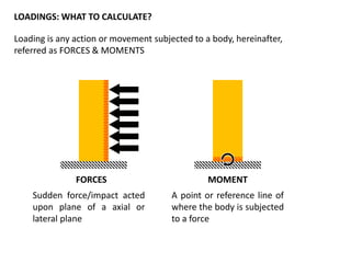
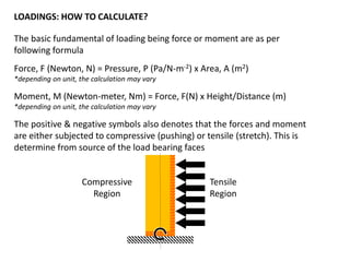


The document explains the fundamental principles of loading in engineering, emphasizing the importance of calculating loads to prevent material failure. It outlines types of loads, examples, and the basic formulas used in calculations, while highlighting that these calculations can vary based on project requirements and codes. The author encourages the application of engineering principles across different fields, reinforcing that understanding loads is critical for anyone involved in construction and design.


