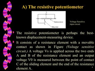
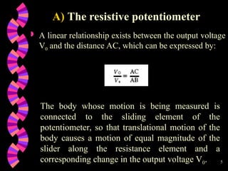
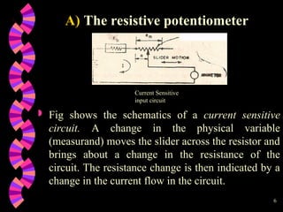
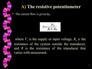
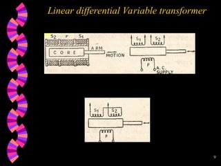
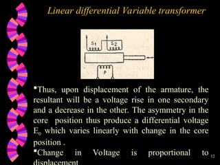
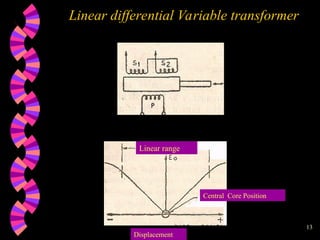
1
Linear & Rotational
Displacement measurement
2
 Translational displacement transducers are
instruments that measure the motion of a body in a
straight line between two points.
 Apart from their use as a primary transducer
measuring the motion of a body, translational
displacement transducers are also widely used as a
secondary component in measurement systems,
where some other physical quantity such as
pressure, force, acceleration or temperature is
translated into a translational motion by the primary
measurement transducer.
Linear Displacement Transducers
3
 Many different types of translational
displacement transducer exist and these, along
with their relative merits and characteristics, are
discussed in the following sections .
Displacement transducers
4
 The resistive potentiometer is perhaps the best-
known displacement-measuring device.
 It consists of a resistance element with a movable
contact as shown in Figure (Voltage sensitive
circuit.) A voltage Vs is applied across the two ends
A and B of the resistance element and an output
voltage V0 is measured between the point of contact
C of the sliding element and the end of the resistance
element A.
A) The resistive potentiometer
Voltage Sensitive
input circuit
5
 A linear relationship exists between the output voltage
V0 and the distance AC, which can be expressed by:
A) The resistive potentiometer
The body whose motion is being measured is
connected to the sliding element of the
potentiometer, so that translational motion of the
body causes a motion of equal magnitude of the
slider along the resistance element and a
corresponding change in the output voltage V0.
6
 Fig shows the schematics of a current sensitive
circuit. A change in the physical variable
(measurand) moves the slider across the resistor and
brings about a change in the resistance of the
circuit. The resistance change is then indicated by a
change in the current flow in the circuit.
A) The resistive potentiometer
Current Sensitive
input circuit
7
 The current flow is given by,
A) The resistive potentiometer
where Vs is the supply or input voltage, Rb is the
resistance of the system outside the transducer,
and R is the resistance of the transducer that
varies with measurand.
8
Linear differential Variable transformer
 LVDT is inductive transducer .Translates liner
motion into electrical signals
 The device has one primary and two secondary
windings with the magnetic core free to move inside
the coils.
 The core is attached to the moving part on which
the displacement measurements are to be made.
 When a.c. current is supplied to the primary
winding, the magnetic flux generated by this coil is
disturbed by the armature so that voltages are
induced in the secondary coil.
9
Linear differential Variable transformer
10
Linear differential Variable transformer
 The secondary windings are symmetrically placed,
are identical and are connected in phase opposition
so that emf induced in them are opposite to each
other. The net output from the transformer is then
the difference between the voltages of the two
secondary windings.
 The position of the magnetic core determines the
flux linkages with each winding, When the core is
placed centrally, equal but opposite emfs are
induced in the secondary windings and zero output
is recorded. This is termed as the balance point or
null position.
11
Linear differential Variable transformer
 A variation in the position of the core from its
null position produces an unbalance in the
resistance of Secondary windings to the
primary windings. The voltage induced in the
secondary winding towards which the core is
displaced increases. A simultaneous decreased
induced voltage results from the other secondary
coil.
12
Linear differential Variable transformer
Thus, upon displacement of the armature, the
resultant will be a voltage rise in one secondary
and a decrease in the other. The asymmetry in the
core position thus produce a differential voltage
E0 which varies linearly with change in the core
position .
Change in Voltage is proportional to
13
Linear differential Variable transformer
Linear range
Central Core Position
Displacement
14
Linear differential Variable transformer
Advantages
 High range (from 1.25mm to 500 mm)
 Low power consumption (<1 w)
 High sensitivity
 Frictionless device
 Tolerant to shocks & vibrations
 Immunized to external effects
15
Linear differential Variable transformer
Disadvantages
 Large displacement required for small o/p
 Sensitive to stray magnet
 Performance affected by temperature
 Limited dynamic response
16
Linear differential Variable transformer
Applications
 Primary transducer – converts
displacement directly to voltage.
 Secondary transducer – for measuring
pressure, force, weight etc.
17
Rotational displacement transducers
 Rotational displacement transducers measure the
angular motion of a body about some rotation axis.
 They are important not only for measuring the
rotation of bodies such as shafts, but also as part of
systems that measure translational displacement by
converting the translational motion to a rotary form.
 The various devices available for measuring
rotational displacements are presented below,
18
Rotational displacement
 Rotational displacement transducers measure the
angular motion of a body about some rotation axis.
 They are important not only for measuring the
rotation of bodies such as shafts, but also as part of
systems that measure translational displacement by
converting the translational motion to a rotary form.
 The various devices available for measuring
rotational displacements are presented below,
19
Rotational displacement
 Angular measurements are made with a device
called tachometer. The dictionary definitions of a
tachometers are :
 *"an instrument used to measure angular velocity
as of shaft, either by registering the number of
rotations during the period of contact, or by
indicating directly the number of rotations per
minute“.
 *"an instrument which either continuously
indicates the value of rotary speed or
continuously displays a reading of average speed
over rapidly operated short intervals of time"
20
Rotational displacement
 Tachometers are broadly classified into two
categories,
 Mechanical tachometers
 Electrical tachometers
 Selection of type of tachometer based on cost,need
of portability, accuracy desired , magnitude of
speed measured and size of the rotating element
21
Revolution counter and timer
 The revolution counter, sometimes called a speed
counter, consists of a worm gear which is also the
shaft attachment and is drives by the speed source.
The worm drives the spur gear which in turn
actuates the pointer on a calibrated dial.
 The pointer indicates the number of revolutions
turned by the input shaft in a certain length of time.
The unit requires a separate timer to measure the
time interval. The revolution counter, thus, gives an
average rotational speed rather than an
instantaneous rotational speed.
22
Revolution counter and timer
 Such speed counters are limited to low speed
engines which permit reading the counter at definite
time intervals. A properly deigned and manufactured
revolution counter would give a satisfactory speed
measure ment upto 2000-3000 rpm.
23
Slipping clutch tachometer
The rotating shaft drives an indicating shaft
through a slipping clutch.
A pointer attached to the indicator shaft moves
over a calibrated scale against the torque of a
spring.
The pointer position gives a measure of the shaft
speed.
24
Slipping clutch tachometer
The rotating shaft drives an indicating shaft
through a slipping clutch.
A pointer attached to the indicator shaft moves
over a calibrated scale against the torque of a
spring.
The pointer position gives a measure of the shaft
speed.
25
Drag Cup tachometer
 The drag-cup tachometer, also known as an eddy-
current tachometer, has a central spindle carrying
a permanent magnet that rotates inside a non-
magnetic drag-cup consisting of a cylindrical
sleeve of electrically conductive material, as
shown in Figure.
26
Drag Cup tachometer
 As the spindle and magnet rotate, a voltage is
induced which causes circulating eddy currents in
the cup. These currents interact with the magnetic
field from the permanent magnet and produce a
torque.
 In response, the drag-cup turns until the induced
torque is balanced by the torque due to the
restraining springs connected to the cup.
27
Drag Cup tachometer
 When equilibrium is reached, the angular
displacement of the cup is proportional to the
rotational velocity of the central spindle. The
instrument has a typical measurement inaccuracy
of š0.5% and is commonly used in the
speedometers of motor vehicles and as a speed
indicator for aero-engines. It is capable of
measuring velocities up to 15 000 rpm.
28
Optical tachometer
 Optical pulses can be
generated by one of the
two alternative
photoelectric techniques
illustrated in Figure.
 In Figure (a), the pulses
are produced as the
windows in a slotted disc
pass in sequence between a
light source and a detector.
Photoelectric pulse generation techniques.
29
Optical tachometer
 The alternative form, Figure
(b), has both light source and
detector mounted on the same
side of a reflective disc which
has black sectors painted onto
it at regular angular intervals.
 Light sources are normally
either lasers or LEDs, with
photodiodes and
phototransistors being used as
detectors.
Optical tachometers yield better accuracy than
other forms of digital tachometer but are not as
reliable because dust and dirt can block light paths
30
Magnetic (Hall-effect) sensing
 The rotating element in Hall-effect or
magnetostrictive tachometers has a very simple
design in the form of a toothed metal gearwheel.
The sensor is a solid-state, Hall-effect device that
is placed between the gear wheel and a permanent
magnet.
31
Magnetic (Hall-effect) sensing
 When an inter tooth gap on the gear wheel is adjacent
to the sensor, the full magnetic field from the magnet
passes through it.
 Later, as a tooth approaches the sensor, the tooth
diverts some of the magnetic field, and so the field
through the sensor is reduced. This causes the sensor
to produce an output voltage that is proportional to
the rotational speed of the gear wheel.
32
Inductive Pick Up
 Variable reluctance velocity transducers, also known as
induction tachometers, are a form of digital tachometer that
use inductive sensing. A more sophisticated version shown
in Figure has a rotating disc that is constructed from a
bonded-fibre material into which soft iron poles are inserted
at regular intervals around its periphery. The sensor consists
of a permanent magnet with a shaped pole piece, which
carries a wound coil.
 The distance between the pick-up and the outer perimeter of
the disc is around 0.5 mm.
33
Inductive Pick Up
 As the disc rotates, the soft iron inserts on the
disc move in turn past the pick-up unit. As each
iron insert moves towards the pole piece, the
reluctance of the magnetic circuit increases and
hence the flux in the pole piece also increases.
 Similarly, the flux in the pole piece decreases as
each iron insert moves away from the sensor. The
changing magnetic flux inside the pick-up coil
causes a voltage to be induced in the coil whose
magnitude is proportional to the rate of change of
flux.
34
Inductive Pick Up
 This voltage is positive whilst the flux is
increasing and negative whilst it is decreasing.
 Thus, the output is a sequence of positive and
negative pulses whose frequency is proportional
to the rotational velocity of the disc. The
maximum angular velocity that the instrument
can measure is limited to about 10000 rpm
because of the finite width of the induced pulses.
35
Inductive Pick Up
 As the velocity increases, the distance between
the pulses is reduced, and at a certain velocity,
the pulses start to overlap. At this point, the pulse
counter ceases to be able to distinguish the
separate pulses. The optical tachometer has
significant advantages in this respect, since the
pulse width is much narrower, allowing
measurement of higher velocities.
36
Stroboscope
 The stroboscopic technique of rotational velocity
measurement operates on a similar physical
principle to digital tachometers except that the
pulses involved consist of flashes of light
generated electronically and whose frequency is
adjustable so that it can be matched with the
frequency of occurrence of some feature on the
rotating body being measured.
37
 This feature can either be some naturally
occurring one such as gear teeth or the spokes of
a wheel, or it can be an artificially created pattern
of black and white stripes. In either case, the
rotating body appears stationary when the
frequencies of the light pulses and body features
are in synchronism.
Stroboscope
38
 Flashing rates available in commercial
stroboscopes vary from 110 up to 150 000 per
minute according to the range of velocity
measurement required, and typical measurement
inaccuracy is +/-1% of the reading. The
instrument is usually in the form of a hand-held
device that is pointed towards the rotating body.
 It must be noted that measurement of the flashing
rate at which the rotating body appears stationary
does not automatically indicate the rotational
velocity, because synchronism also occurs when
the flashing rate is some integral sub-multiple of
the rotational speed.
Stroboscope
39
 The practical procedure followed is therefore to
adjust the flashing rate until synchronism is
obtained at the largest flashing rate possible, R1.
The flashing rate is then carefully decreased until
synchronism is again achieved at the next lower
flashing rate, R2. The rotational velocity is then
given by:
Stroboscope

Linear-and-Rotational-Displacement-Measurement.ppt

  • 1.
  • 2.
    2  Translational displacementtransducers are instruments that measure the motion of a body in a straight line between two points.  Apart from their use as a primary transducer measuring the motion of a body, translational displacement transducers are also widely used as a secondary component in measurement systems, where some other physical quantity such as pressure, force, acceleration or temperature is translated into a translational motion by the primary measurement transducer. Linear Displacement Transducers
  • 3.
    3  Many differenttypes of translational displacement transducer exist and these, along with their relative merits and characteristics, are discussed in the following sections . Displacement transducers
  • 4.
    4  The resistivepotentiometer is perhaps the best- known displacement-measuring device.  It consists of a resistance element with a movable contact as shown in Figure (Voltage sensitive circuit.) A voltage Vs is applied across the two ends A and B of the resistance element and an output voltage V0 is measured between the point of contact C of the sliding element and the end of the resistance element A. A) The resistive potentiometer Voltage Sensitive input circuit
  • 5.
    5  A linearrelationship exists between the output voltage V0 and the distance AC, which can be expressed by: A) The resistive potentiometer The body whose motion is being measured is connected to the sliding element of the potentiometer, so that translational motion of the body causes a motion of equal magnitude of the slider along the resistance element and a corresponding change in the output voltage V0.
  • 6.
    6  Fig showsthe schematics of a current sensitive circuit. A change in the physical variable (measurand) moves the slider across the resistor and brings about a change in the resistance of the circuit. The resistance change is then indicated by a change in the current flow in the circuit. A) The resistive potentiometer Current Sensitive input circuit
  • 7.
    7  The currentflow is given by, A) The resistive potentiometer where Vs is the supply or input voltage, Rb is the resistance of the system outside the transducer, and R is the resistance of the transducer that varies with measurand.
  • 8.
    8 Linear differential Variabletransformer  LVDT is inductive transducer .Translates liner motion into electrical signals  The device has one primary and two secondary windings with the magnetic core free to move inside the coils.  The core is attached to the moving part on which the displacement measurements are to be made.  When a.c. current is supplied to the primary winding, the magnetic flux generated by this coil is disturbed by the armature so that voltages are induced in the secondary coil.
  • 9.
  • 10.
    10 Linear differential Variabletransformer  The secondary windings are symmetrically placed, are identical and are connected in phase opposition so that emf induced in them are opposite to each other. The net output from the transformer is then the difference between the voltages of the two secondary windings.  The position of the magnetic core determines the flux linkages with each winding, When the core is placed centrally, equal but opposite emfs are induced in the secondary windings and zero output is recorded. This is termed as the balance point or null position.
  • 11.
    11 Linear differential Variabletransformer  A variation in the position of the core from its null position produces an unbalance in the resistance of Secondary windings to the primary windings. The voltage induced in the secondary winding towards which the core is displaced increases. A simultaneous decreased induced voltage results from the other secondary coil.
  • 12.
    12 Linear differential Variabletransformer Thus, upon displacement of the armature, the resultant will be a voltage rise in one secondary and a decrease in the other. The asymmetry in the core position thus produce a differential voltage E0 which varies linearly with change in the core position . Change in Voltage is proportional to
  • 13.
    13 Linear differential Variabletransformer Linear range Central Core Position Displacement
  • 14.
    14 Linear differential Variabletransformer Advantages  High range (from 1.25mm to 500 mm)  Low power consumption (<1 w)  High sensitivity  Frictionless device  Tolerant to shocks & vibrations  Immunized to external effects
  • 15.
    15 Linear differential Variabletransformer Disadvantages  Large displacement required for small o/p  Sensitive to stray magnet  Performance affected by temperature  Limited dynamic response
  • 16.
    16 Linear differential Variabletransformer Applications  Primary transducer – converts displacement directly to voltage.  Secondary transducer – for measuring pressure, force, weight etc.
  • 17.
    17 Rotational displacement transducers Rotational displacement transducers measure the angular motion of a body about some rotation axis.  They are important not only for measuring the rotation of bodies such as shafts, but also as part of systems that measure translational displacement by converting the translational motion to a rotary form.  The various devices available for measuring rotational displacements are presented below,
  • 18.
    18 Rotational displacement  Rotationaldisplacement transducers measure the angular motion of a body about some rotation axis.  They are important not only for measuring the rotation of bodies such as shafts, but also as part of systems that measure translational displacement by converting the translational motion to a rotary form.  The various devices available for measuring rotational displacements are presented below,
  • 19.
    19 Rotational displacement  Angularmeasurements are made with a device called tachometer. The dictionary definitions of a tachometers are :  *"an instrument used to measure angular velocity as of shaft, either by registering the number of rotations during the period of contact, or by indicating directly the number of rotations per minute“.  *"an instrument which either continuously indicates the value of rotary speed or continuously displays a reading of average speed over rapidly operated short intervals of time"
  • 20.
    20 Rotational displacement  Tachometersare broadly classified into two categories,  Mechanical tachometers  Electrical tachometers  Selection of type of tachometer based on cost,need of portability, accuracy desired , magnitude of speed measured and size of the rotating element
  • 21.
    21 Revolution counter andtimer  The revolution counter, sometimes called a speed counter, consists of a worm gear which is also the shaft attachment and is drives by the speed source. The worm drives the spur gear which in turn actuates the pointer on a calibrated dial.  The pointer indicates the number of revolutions turned by the input shaft in a certain length of time. The unit requires a separate timer to measure the time interval. The revolution counter, thus, gives an average rotational speed rather than an instantaneous rotational speed.
  • 22.
    22 Revolution counter andtimer  Such speed counters are limited to low speed engines which permit reading the counter at definite time intervals. A properly deigned and manufactured revolution counter would give a satisfactory speed measure ment upto 2000-3000 rpm.
  • 23.
    23 Slipping clutch tachometer Therotating shaft drives an indicating shaft through a slipping clutch. A pointer attached to the indicator shaft moves over a calibrated scale against the torque of a spring. The pointer position gives a measure of the shaft speed.
  • 24.
    24 Slipping clutch tachometer Therotating shaft drives an indicating shaft through a slipping clutch. A pointer attached to the indicator shaft moves over a calibrated scale against the torque of a spring. The pointer position gives a measure of the shaft speed.
  • 25.
    25 Drag Cup tachometer The drag-cup tachometer, also known as an eddy- current tachometer, has a central spindle carrying a permanent magnet that rotates inside a non- magnetic drag-cup consisting of a cylindrical sleeve of electrically conductive material, as shown in Figure.
  • 26.
    26 Drag Cup tachometer As the spindle and magnet rotate, a voltage is induced which causes circulating eddy currents in the cup. These currents interact with the magnetic field from the permanent magnet and produce a torque.  In response, the drag-cup turns until the induced torque is balanced by the torque due to the restraining springs connected to the cup.
  • 27.
    27 Drag Cup tachometer When equilibrium is reached, the angular displacement of the cup is proportional to the rotational velocity of the central spindle. The instrument has a typical measurement inaccuracy of š0.5% and is commonly used in the speedometers of motor vehicles and as a speed indicator for aero-engines. It is capable of measuring velocities up to 15 000 rpm.
  • 28.
    28 Optical tachometer  Opticalpulses can be generated by one of the two alternative photoelectric techniques illustrated in Figure.  In Figure (a), the pulses are produced as the windows in a slotted disc pass in sequence between a light source and a detector. Photoelectric pulse generation techniques.
  • 29.
    29 Optical tachometer  Thealternative form, Figure (b), has both light source and detector mounted on the same side of a reflective disc which has black sectors painted onto it at regular angular intervals.  Light sources are normally either lasers or LEDs, with photodiodes and phototransistors being used as detectors. Optical tachometers yield better accuracy than other forms of digital tachometer but are not as reliable because dust and dirt can block light paths
  • 30.
    30 Magnetic (Hall-effect) sensing The rotating element in Hall-effect or magnetostrictive tachometers has a very simple design in the form of a toothed metal gearwheel. The sensor is a solid-state, Hall-effect device that is placed between the gear wheel and a permanent magnet.
  • 31.
    31 Magnetic (Hall-effect) sensing When an inter tooth gap on the gear wheel is adjacent to the sensor, the full magnetic field from the magnet passes through it.  Later, as a tooth approaches the sensor, the tooth diverts some of the magnetic field, and so the field through the sensor is reduced. This causes the sensor to produce an output voltage that is proportional to the rotational speed of the gear wheel.
  • 32.
    32 Inductive Pick Up Variable reluctance velocity transducers, also known as induction tachometers, are a form of digital tachometer that use inductive sensing. A more sophisticated version shown in Figure has a rotating disc that is constructed from a bonded-fibre material into which soft iron poles are inserted at regular intervals around its periphery. The sensor consists of a permanent magnet with a shaped pole piece, which carries a wound coil.  The distance between the pick-up and the outer perimeter of the disc is around 0.5 mm.
  • 33.
    33 Inductive Pick Up As the disc rotates, the soft iron inserts on the disc move in turn past the pick-up unit. As each iron insert moves towards the pole piece, the reluctance of the magnetic circuit increases and hence the flux in the pole piece also increases.  Similarly, the flux in the pole piece decreases as each iron insert moves away from the sensor. The changing magnetic flux inside the pick-up coil causes a voltage to be induced in the coil whose magnitude is proportional to the rate of change of flux.
  • 34.
    34 Inductive Pick Up This voltage is positive whilst the flux is increasing and negative whilst it is decreasing.  Thus, the output is a sequence of positive and negative pulses whose frequency is proportional to the rotational velocity of the disc. The maximum angular velocity that the instrument can measure is limited to about 10000 rpm because of the finite width of the induced pulses.
  • 35.
    35 Inductive Pick Up As the velocity increases, the distance between the pulses is reduced, and at a certain velocity, the pulses start to overlap. At this point, the pulse counter ceases to be able to distinguish the separate pulses. The optical tachometer has significant advantages in this respect, since the pulse width is much narrower, allowing measurement of higher velocities.
  • 36.
    36 Stroboscope  The stroboscopictechnique of rotational velocity measurement operates on a similar physical principle to digital tachometers except that the pulses involved consist of flashes of light generated electronically and whose frequency is adjustable so that it can be matched with the frequency of occurrence of some feature on the rotating body being measured.
  • 37.
    37  This featurecan either be some naturally occurring one such as gear teeth or the spokes of a wheel, or it can be an artificially created pattern of black and white stripes. In either case, the rotating body appears stationary when the frequencies of the light pulses and body features are in synchronism. Stroboscope
  • 38.
    38  Flashing ratesavailable in commercial stroboscopes vary from 110 up to 150 000 per minute according to the range of velocity measurement required, and typical measurement inaccuracy is +/-1% of the reading. The instrument is usually in the form of a hand-held device that is pointed towards the rotating body.  It must be noted that measurement of the flashing rate at which the rotating body appears stationary does not automatically indicate the rotational velocity, because synchronism also occurs when the flashing rate is some integral sub-multiple of the rotational speed. Stroboscope
  • 39.
    39  The practicalprocedure followed is therefore to adjust the flashing rate until synchronism is obtained at the largest flashing rate possible, R1. The flashing rate is then carefully decreased until synchronism is again achieved at the next lower flashing rate, R2. The rotational velocity is then given by: Stroboscope