Introduction
Spillway definition
Safety valve ,safety against overtopping, removal of surplus flow
Considerations for spillway design:
Selection of spillway layout
Spillway components (approach channel, control structure, discharge
channel, terminal structure)
Hydraulic computations
Stability studies
Economic studies
An acceptable design can only be obtained as a consequence of
serious considerations of factors affecting the final choice. This choice
must be the safest and the most economical of all possible solutions.
3.
Introduction
Layout selectiondepends on various
factors such as;
Type of dam
Embankment (separate,
shaft or tunnel spillway)
Concrete dam(overflow,
siphon, overfall, chute side
channe…)
Amount of excavation and
possibility for its use as
embankment material
Stability of foundation and
excavation
Hydraulic conditions
A spillway may be located either
in the middle of the dam or at
the end of the dam near
abutment.
In some cases, the spillway is
located away from the dam as
an independent structure if there
is a suitable saddle (saddle
spillway)
Generally, a saddle spillway is
designed as an auxiliary or an
emergency spillway in addition to
the main spillway at the dam site.
Selection of Spillway Layout
Introduction
Essential Requirementsof a Spillway
It must have adequate discharge capacity
It must he hydraulically and structurally safe
The surface of the spillway must be erosion resistant.
The spillway must be so located that the spillway discharge
does not erode or undermine the downstream toe of the
dam.
It should be provided with some device for the dissipation of
excess energy.
The spillway discharge should not exceed the safe discharge
capacity of the downstream channel
6.
Introduction
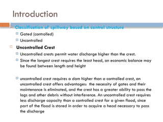
Classification ofspillway based on control structure
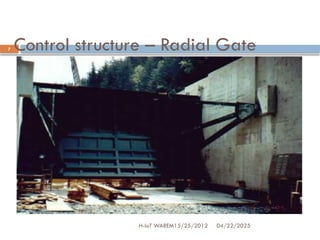
Gated (controlled)
Uncontrolled
Uncontrolled Crest
Uncontrolled crests permit water discharge higher than the crest.
Since the longest crest requires the least head, an economic balance may
be found between length and height
uncontrolled crest requires a dam higher than a controlled crest, an
uncontrolled crest offers advantages: the necessity of gates and their
maintenance is eliminated, and the crest has a greater ability to pass the
logs and other debris without interference. An uncontrolled crest requires
less discharge capacity than a controlled crest for a given flood, since
part of the flood is stored in order to acquire a head necessary to pass
the discharge
a) Overflow Spillways
sectionof a dam that allows water to pass over its crest
widely used on gravity, arch, & buttress dam
Discharge of an Overflow Spillway
b) Chute Spillways
• formed by spillways that flow over a crest into a steep-sloped
open channel
• chute width is often constant:
-narrowed for economy
-widened to decrease discharge velocity
Classification based on the pertinent feature
9.
Spillway type
04/22/2025
H-IoT WAREM15/25/2012
9
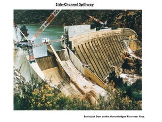
c)Side-Channel Spillways
spillway in which flow, after passing over the crest,
is carried away in a channel running parallel to the
crest
used in narrow canyons in which there is sufficient
crest length for overflow or chute is available
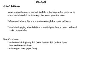
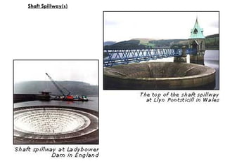
d) Shaft Spillways
waterdrops through a vertical shaft in a the foundation material to
a horizontal conduit that conveys the water past the dam
*often used where there is not room enough for other spillways
*possible clogging with debris a potential problem; screens and trash
racks protect inlet
Flow Conditions
- outlet conduit is partly full (weir flow) or full (orifice flow)
- intermediate condition
- submerged inlet (pipe flow)
SPILLWAYS
e) Siphon Spillways
airvent used automatically maintain the water-surface elevation
large capacity not needed, good for limited space
* At low flow: it acts like an overflow spillway
* At high flow: the siphon action removes the water thru the structure
until reservoir drops to the elevation at the upper lip of entrance
f) Service and Emergency Spillways
-extra spillways provided on a project in rare case of extreme floods
(emergency)
-used to convey frequently occurring outflow rates (service)
SPILLWAYS
14.
Types of Spillway
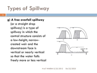
g)A free overfall spillway
(or a straight drop
spillway) is a type of
spillway in which the
control structure consists of
a low-height, narrow-
crested weir and the
downstream face is
vertical or nearly vertical
so that the water falls
freely more or less vertical
04/22/2025
14
H-IoT WAREM15/25/2012
15.
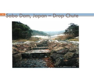
Sabo Dam, Japan– Drop Chute
04/22/2025
H-IoT WAREM15/25/2012
15
16.
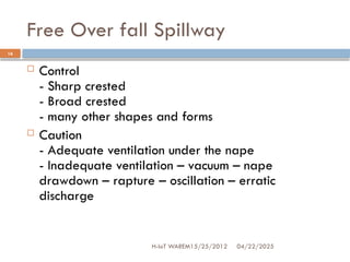
Free Over fallSpillway
04/22/2025
H-IoT WAREM15/25/2012
16
Control
- Sharp crested
- Broad crested
- many other shapes and forms
Caution
- Adequate ventilation under the nape
- Inadequate ventilation – vacuum – nape
drawdown – rapture – oscillation – erratic
discharge
17.
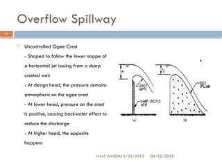
Overflow Spillway
UncontrolledOgee Crest
- Shaped to follow the lower nappe of
a horizontal jet issuing from a sharp
crested weir
- At design head, the pressure remains
atmospheric on the ogee crest
- At lower head, pressure on the crest
is positive, causing backwater effect to
reduce the discharge
- At higher head, the opposite
happens
04/22/2025
17
H-IoT WAREM15/25/2012
18.
Introduction
Utility andOperational Aspects
From the standpoint of serviceability, spillways may be defined in three broad classes as follows.
• Service Spillways
Include any spillway that may be utilized without significant damage to the structure or downstream channel. As a
general rule, service spillways have paved channels and suitable energy dissipators.
• Limited Service and Additional Spillways
Include any spillway that may be utilized infrequently for operation of the reservoir without incurring excessive damage.
Some extraordinary maintenance at infrequent intervals would be acceptable in order to reduce initial construction costs,
but not to the extent of imposing significant limitations on the optimum utilization of the reservoir’s controlled storage
capacity under normal operating conditions.
• Emergency Spillways
Include any spillway, the use of which to be avoided as long as possible used to prevent major damage to the spillway
structure or to downstream areas. Emergency spillways may involve partial control by so-called ‘‘Fuse Plugs’’ or ‘‘Flash
Boards.’’ The overall advantages and disadvantages of service, additional, and emergency spillways should be
considered in the planning and design of a reservoir project. Besides the aforementioned, the spillways can be classified
according to the control structure, namely controlled or gated crest and uncontrolled or ungated crest.
19.
Introduction
The followingaspects are involved in the design of
spillways:
Hydrology
Topography and geology
Utility and operational aspects
Constructional and structural aspects
Various Aspects Involved in a Spillway
Design
20.
Introduction
Hydrology
Thehydrological aspects relevant to the spillway design
are:
Estimation of inflow design flood (IDF)
Selection of spillway design flood
Determination of spillway outflow discharge
Determination of frequency of spillway use
21.
Introduction
Topography andGeology
Topography and geology, with selected subsurface explorations, have greater influence on the
location and type of spillway than any other factors. These considerations thus determine the type
and location of a spillway as follows:
Ogee spillway: Most commonly used as the integral overflow section of a concrete or
a masonry dam.
Chute spillway: Adopted in a site where a suitable foundation with moderate depth of
excavation is available, where topography of the site permits the use of a relatively
short channel, or where spillway excavation can be used economically in the dam.
Side channel spillway: Suitable for earth or rock-fill dams in narrow canyons and for
other situations where direct overflow is not permissible.
Shaft spillway/Tunnel spillway: Used advantageously at dam sites in narrow canyons
where abutments rise steeply or where a diversion tunnel or conduit is available for use
as the downstream leg.
Siphon spillway: Used when there is a desire for an automatic operation without
mechanical parts and the discharge to be passed is small.
Free over-fall spillway: Suitable for arch.
22.
Spillway Design Data
04/22/2025
H-IoTWAREM15/25/2012
22
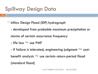
Inflow Design Flood (IDF) hydrograph
- developed from probable maximum precipitation or
storms of certain occurrence frequency
- life loss use PMP
- if failure is tolerated, engineering judgment cost-
benefit analysis use certain return-period flood
(standard flood)
23.
Spillway Design Data(cont’d)
04/22/2025
H-IoT WAREM15/25/2012
23
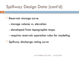
Reservoir storage curve
- storage volume vs. elevation
- developed from topographic maps
- requires reservoir operation rules for modeling
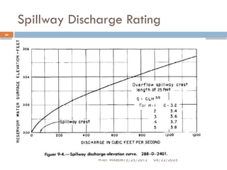
Spillway discharge rating curve
Spillway Design Procedure
04/22/2025
H-IoTWAREM15/25/2012
25
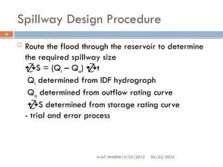
Route the flood through the reservoir to determine
the required spillway size
S = (Qi – Qo) t
Qi determined from IDF hydrograph
Qo determined from outflow rating curve
S determined from storage rating curve
- trial and error process
Economic Analysis
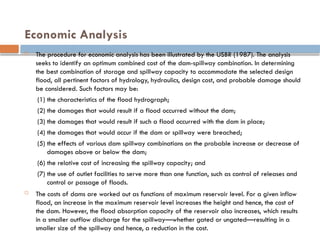
Theprocedure for economic analysis has been illustrated by the USBR (1987). The analysis
seeks to identify an optimum combined cost of the dam-spillway combination. In determining
the best combination of storage and spillway capacity to accommodate the selected design
flood, all pertinent factors of hydrology, hydraulics, design cost, and probable damage should
be considered. Such factors may be:
(1) the characteristics of the flood hydrograph;
(2) the damages that would result if a flood occurred without the dam;
(3) the damages that would result if such a flood occurred with the dam in place;
(4) the damages that would occur if the dam or spillway were breached;
(5) the effects of various dam spillway combinations on the probable increase or decrease of
damages above or below the dam;
(6) the relative cost of increasing the spillway capacity; and
(7) the use of outlet facilities to serve more than one function, such as control of releases and
control or passage of floods.
The costs of dams are worked out as functions of maximum reservoir level. For a given inflow
flood, an increase in the maximum reservoir level increases the height and hence, the cost of
the dam. However, the flood absorption capacity of the reservoir also increases, which results
in a smaller outflow discharge for the spillway—whether gated or ungated—resulting in a
smaller size of the spillway and hence, a reduction in the cost.
28.
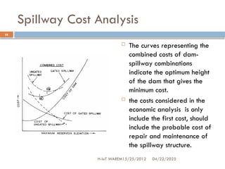
Spillway Cost Analysis
The curves representing the
combined costs of dam-
spillway combinations
indicate the optimum height
of the dam that gives the
minimum cost.
the costs considered in the
economic analysis is only
include the first cost, should
include the probable cost of
repair and maintenance of
the spillway structure.
04/22/2025
28
H-IoT WAREM15/25/2012
29.
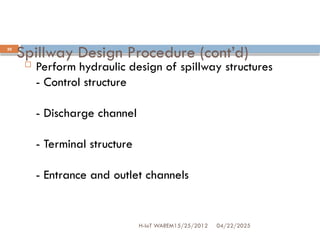
Spillway Design Procedure(cont’d)
04/22/2025
H-IoT WAREM15/25/2012
29
Select spillway type and control structure
- service, auxiliary and emergency spillways to
operate at increasingly higher reservoir levels
- whether to include control structure or equipment –
a question of regulated or unregulated discharge
30.
Spillway Design Procedure(cont’d)
04/22/2025
H-IoT WAREM15/25/2012
30
Perform hydraulic design of spillway structures
- Control structure
- Discharge channel
- Terminal structure
- Entrance and outlet channels
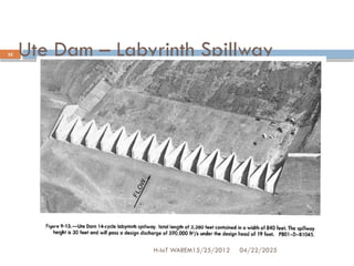
Ute Dam –Labyrinth Spillway
04/22/2025
H-IoT WAREM15/25/2012
35
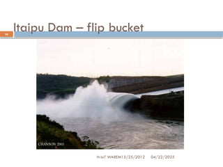
36.
Itaipu Dam –flip bucket
04/22/2025
H-IoT WAREM15/25/2012
36
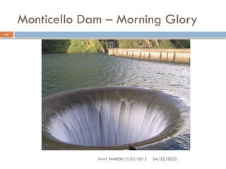
37.
Monticello Dam –Morning Glory
04/22/2025
H-IoT WAREM15/25/2012
37
38.
Introduction
Constructional andStructural Aspects
River valley projects with multiple purposes are usually phased over long
periods of time to suit the requirements of irrigation and power, financial
allocations, and progress of rehabilitation of the project-affected population.
It would be necessary to plan the construction schedule, as well as spillway
features, in such a way that the temporary passages of flow do not cause
undesirable flow conditions. Hydraulic model study is the best means to
visualize these effects and to evolve suitable designs. The choice of earth- and
rock-fill dams is often based on the availability of material from the
excavation for the spillways. In such situations, unlined rock spillways and
unlined cascade spillways may be preferred over chute and side channel
spillways.
Roller-compacted concrete method of construction is cost-effective, typically
faster, and causes minimum project disruption. This technique also facilitates the
provision of stepped spillways 30 to 60 cm ensure energy dissipation on the
flow surface itself at almost double that of an unstepped, smooth spillway.
39.
Spillway Design Flood:Estimation and Selection
Introduction
The overtopping of dams causes more than a third of all dam failures.
Equipment malfunctions or operational errors are sometimes to blame, but
the principal cause is inadequate spillway capacity. Thus, the importance of
spillway design flood cannot be over emphasized. In many cases, because
the consequences of dam failure would be so severe, no significant level of
failure can be tolerated, and protection should be provided up to the
maximum flood levels. However, where the consequences would be less
serious, the probability of slight failure would be acceptable, and the
expenditure for protecting the dam can be reduced. Besides, the distinction
can also be made between dam safety and works discharge capacity. This
approach, in practical terms, leads to two design floods and their spillway
discharge capacity.
40.
Spillway Design Flood:Estimation and Selection
a) The Safety Check Flood: This flood is often made equal to the
Probable Maximum Flood (PMF). It is considered acceptable
practice for the crest structure, waterway, and energy
dissapator to be on the verge of failure, but to exhibit
marginally safe performance and an accepted risk of damage
without total failure.
b) The Design Flood: This flood strictly represents the inflow,
which must be discharged under normal conditions with a
safety margin provided by the free board. The design flood is
usually taken as a percentage of PMF or is a flood with a
given probability of exceeding its capacity, such as 1:100,
1:1000, etc.
41.
Introduction
Estimation ofSpillway Design Flood
The estimation of spillway design flood or the inflow
design flood is an exercise involving diverse disciplines:
hydrology, meteorology, statistics and probability.
There is a great variety of methods used around the
world to determine exceptional floods and their
characteristics. ICOLD (1992) groups all these methods
under the two main categories:
Editor's Notes
#21 The class and amount of excavation, possibility of seepage and piping, value of excavated material for other purposes, possibility of scour and subsequent need for lining, location of faults, type of foundation, and bearing pressures allowed are some of the items considered.