2
Sewers
• It isthe pipe or conduit for carrying sewage. It is generally closed and
flow takes place under gravity (Atmospheric Pressure).
Classification of sewers
▫ Sanitary Sewers
▫ Storm Sewers
▫ Combined Sewers
▫ House Sewers
▫ Lateral Sewers
▫ Sub-main Sewers
▫ Main/ Trunk Sewers
▫ Outfall Sewers
3.
3
• Sanitary Sewers
Pipesor conduits that carry sanitary sewage i.e., wastewater from municipality
including domestic and industrial wastewaters.
• Storm Sewers
Pipes or conduits carries storm sewage i.e., surface water runoff from rain,
melting snow etc. as well as water from street wash.
• Combined Sewers
Sewers that carry mixture of raw sanitary sewage and runoff from paved
surfaces.
Types of Sewers
4.
4
• House Sewers
Itis the sewer conveying sewage from plumbing system of a building or house
to common/municipal/sanitary sewers.
• Lateral Sewers
Sewer that carry discharge from two or more house sewers.
• Sub-main Sewers
Sewer that carry discharge from two or more laterals.
Types of Sewers
5.
5
• Main/ TrunkSewers
Sewers carrying discharge from two or more sub-mains
• Outfall Sewers
Sewers that receives discharge from all collecting system and conveys it to the
point of final disposal.
Types of Sewers
7
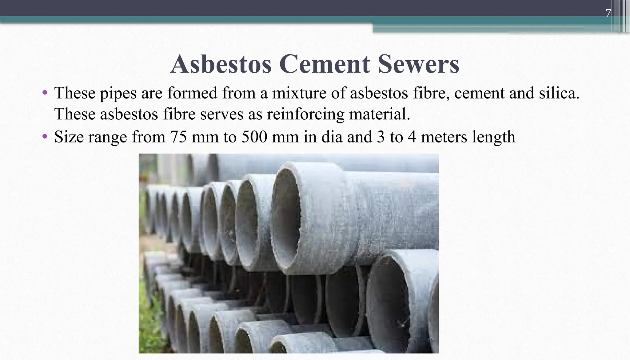
Asbestos Cement Sewers
•These pipes are formed from a mixture of asbestos fibre, cement and silica.
These asbestos fibre serves as reinforcing material.
• Size range from 75 mm to 500 mm in dia and 3 to 4 meters length
8.
8
Advantages Disadvantages
• Goodstrength against internal
pressure
• Light in weight
• Can be cut easily and jointed
• Good resistance to salts and
corrosive materials
• Surface is smooth
• They are brittle
• Less strength against external load
• Susceptible to sulphide corrosion
• They are used as verticals only
Asbestos Cement Sewers
9.
9
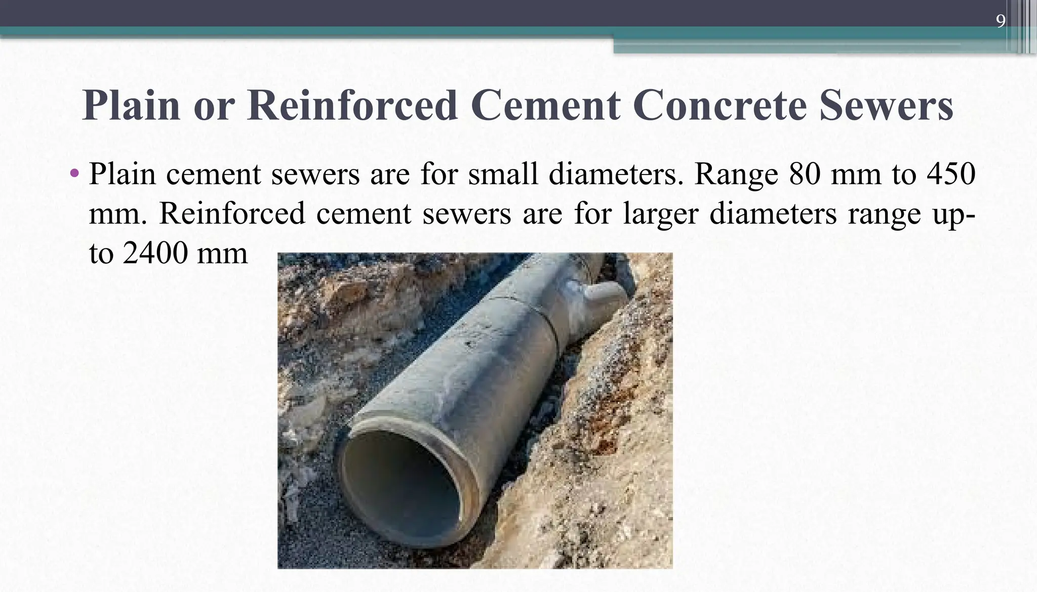
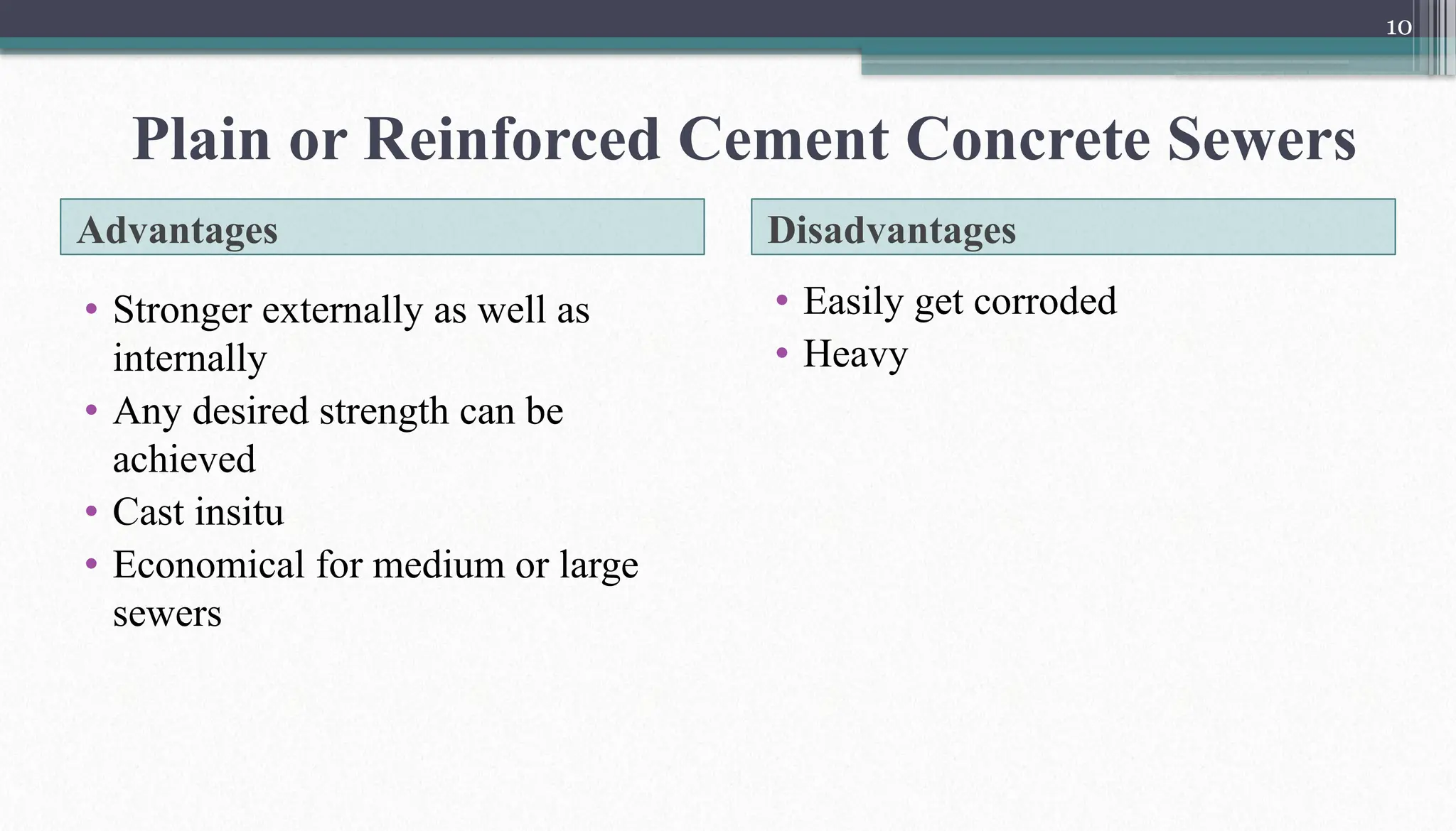
Plain or ReinforcedCement Concrete Sewers
• Plain cement sewers are for small diameters. Range 80 mm to 450
mm. Reinforced cement sewers are for larger diameters range up-
to 2400 mm
10.
10
Advantages Disadvantages
• Strongerexternally as well as
internally
• Any desired strength can be
achieved
• Cast insitu
• Economical for medium or large
sewers
• Easily get corroded
• Heavy
Plain or Reinforced Cement Concrete Sewers
11.
11
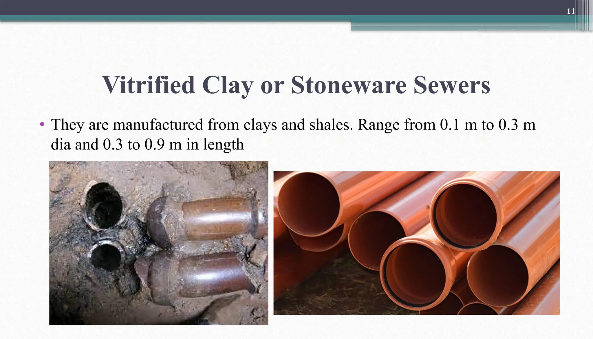
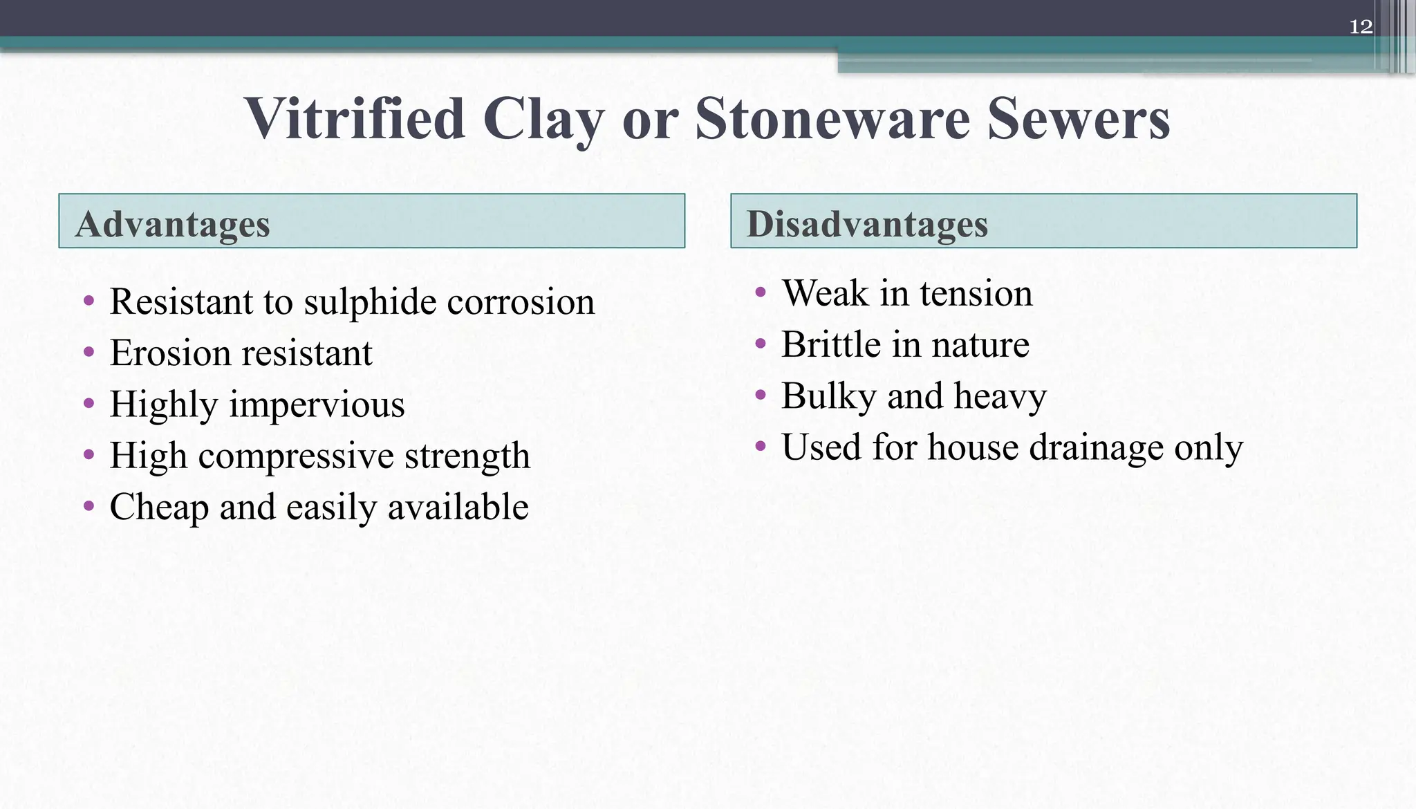
Vitrified Clay orStoneware Sewers
• They are manufactured from clays and shales. Range from 0.1 m to 0.3 m
dia and 0.3 to 0.9 m in length
12.
12
Advantages Disadvantages
• Resistantto sulphide corrosion
• Erosion resistant
• Highly impervious
• High compressive strength
• Cheap and easily available
• Weak in tension
• Brittle in nature
• Bulky and heavy
• Used for house drainage only
Vitrified Clay or Stoneware Sewers
13.
13
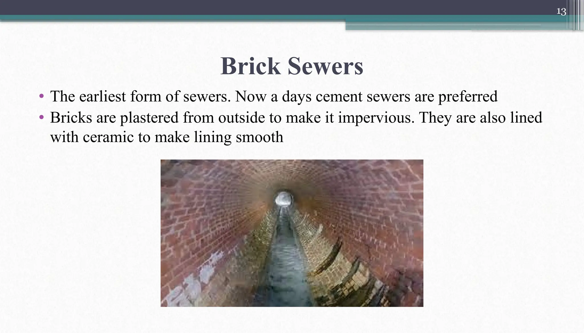
Brick Sewers
• Theearliest form of sewers. Now a days cement sewers are preferred
• Bricks are plastered from outside to make it impervious. They are also lined
with ceramic to make lining smooth
14.
14
Cast Iron Sewers
•They possess high strength.
• Size range from 150mm to 750mm in dia and 3 to 3.5m in length
• They can’t resist chemicals hence they are painted to increase their
resistance
• They are costly and must be used under following conditions
Heavy external loads
High internal pressure
Under expensive road surface
Temperature variations
Vibrations
Wet ground conditions
15.
15
Steel Sewers
• Theyare made of steel
• Impervious in nature
• Light in weight and flexible
• Can absorb vibrations and shocks
• Large diameter
• Corrosion free
• Easily welded
• High initial cost
16.
16
Plastic Sewers
• Theuse of plastic sewer line is still in the experimental stage
• Made up of PVC
• Available in longer lengths
• Corrosion resistant
17.
17
Steps of SewerInstallation
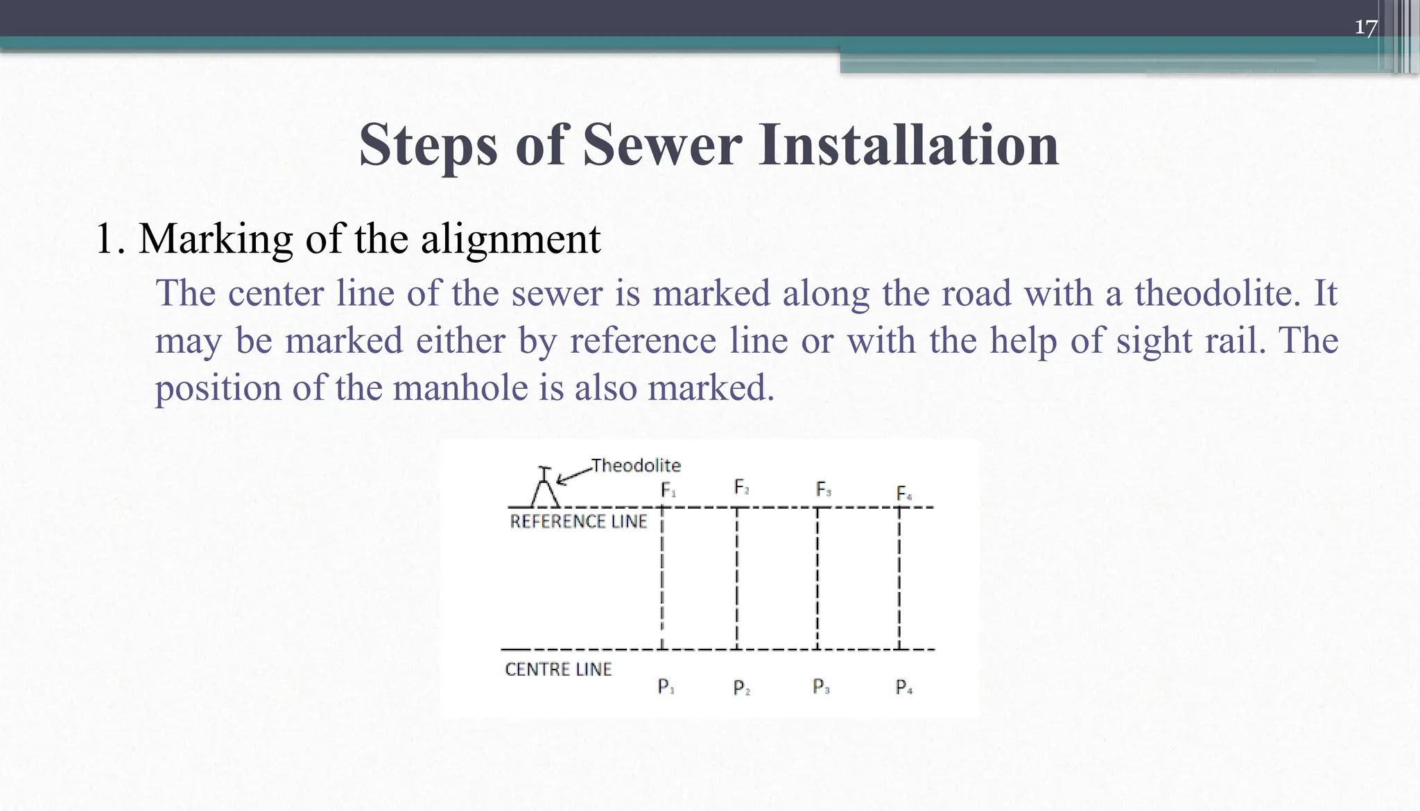
1. Marking of the alignment
The center line of the sewer is marked along the road with a theodolite. It
may be marked either by reference line or with the help of sight rail. The
position of the manhole is also marked.
18.
18
Steps of SewerInstallation
2. Excavation of trench
After marking the center line of the sewer, the excavation of trench is
started. The excavation may be carried out either by manual labour or by
machines like power shovels, track excavators etc.
The width of the trench at the bottom is generally kept 15 cm more than
the dia of sewer pipe. At the point of sewer joint, the width of the trench is
made 60 cm for a length of 60 cm. The invert level is fixed by boning rod.
19.
19
Steps of SewerInstallation
3. Timbering of trench
When, in ordinary soil, the depth of excavation is more than 2 m, timber
bracing or sheet piling is provided on both sides of the trench so that it
may not collapse. The extent of timbering required depends upon the type
of soil and the depth of excavation.
4. Dewatering of trench
If water is met with during excavation, it is removed by pumping or any
other suitable method.
20.
20
Steps of SewerInstallation
5. Preparation of sub-grade
For soft soil, the bed of the sewer is prepared by plain concrete (1:3:6).
The thickness of concrete varies from 15 to 20 cm. The bedding layer is
not required in case of rocky or hard soil.
6. Laying and joining of pipes
The sewers are laid along the trench very carefully. Then the joining of the
sewer is done as per requirements. After joining, both sides of the pipe are
finished with concrete.
7. Testing of leakage
The leakage in the pipe joints or any other points is tested by water test or
air test
21.
21
Steps of SewerInstallation
8. Testing of straightness of alignment and obstructions
The straightness of the sewer pipe and the presence of any obstruction are
tested by placing a mirror at one end of the sewer and a lamp at the other
end. If the pipeline is straight, the full circle of light will be observed.
The presence of an obstruction in the pipe can also be tested by inserting a
smooth ball at the upper end of the sewer. The dia of the ball is 13 mm less
than the internal diameter of the sewer. If there is no obstruction inside the
sewer, the ball shall roll down and reach the lower end of the sewer.
9. Back filling
Lastly, the trenches are filled up with the excavated earth in layers about
15 cm thick. Each layer is properly watered and rammed.


![Sewer appurtenances [recovered]](https://cdn.slidesharecdn.com/ss_thumbnails/sewerappurtenancesrecovered-180318135220-thumbnail.jpg?width=640&height=640&fit=bounds)