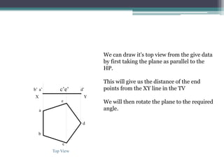
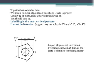
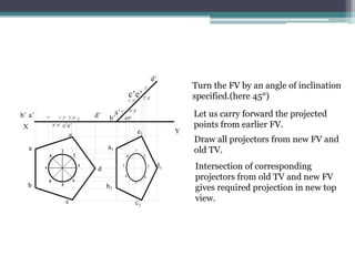
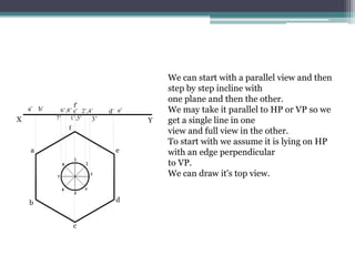
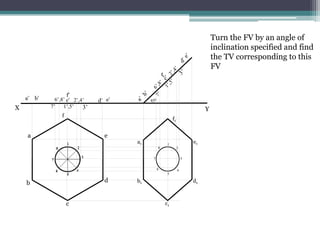
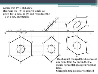
Lecture 3
Projection of Planes
ME 119: P2,P4,& P12,P14
January - April 2012
Prof. Jitendra Shah
• A pentagonal lamina of 40 mm side has a
circular hole of 15 mm diameter in its centre.
The plane stands on one of its sides on HP
with its plane perpendicular to VP and 45°
inclined to HP. Draw the projections.
•PERPENDICULAR TO HP AND
PARALLEL TO VP
•PERPENDICULAR TO VP AND
PARALLEL TO HP
•PERPENDICULAR TO BOTH HP
AND VP
•PERPENDICULAR TO ONE
PLANE AND INCLINED TO THE
OTHER PLANE
•INCLINED TO THE BOTH HP
AND VP
•AUXILLARY PLANE VIEWS FOR
TRUE SHAPE
We can draw it's top view from the give data
by first taking the plane as parallel to the
HP.
This will give us the distance of the end
points from the XY line in the TV
We will then rotate the plane to the required
angle.
a’
b’ d’
d
a
c’e’
b
c
X
e
Y
Top View
Top view has a circular hole.
We need a number of points on this shape (circle to project.
Usually 12 or more. Here we are only showing 8).
You should take 12.
Labelling is the most critical process.
It must be in order . (e.g you may use a, b, c in TV and a', b' , c' in FV.
a’
b’ d’
d
a
c’e’
b
c
X
e
Y
Project all points of interest on
FV(coincident with XY line, as the
plate is assumed to be lying on HP)
7’
6’,8’
1’,5’ 2’,4’ 3’
a’
b’ d’
d
a
c’e’
b
c
X
e
Y
7’
6’,8’
1’,5’ 2’,4’ 3’
b1
c1
d1
a1
d’
a’
b’
c’e’
e1
450
7’ 6’,8’
1’,5’
2’,4’
3’
1
2
3
4
5
6
7
8
Turn the FV by an angle of inclination
specified.(here 45°)
Let us carry forward the projected
points from earlier FV.
Draw all projectors from new FV and
old TV.
Intersection of corresponding
projectors from old TV and new FV
gives required projection in new top
view.
• A regular hexagonal lamina of 30 mm side has a
central hole of 20 mm diameter. A side of lamina
is inclined at 35°. Draw the front and top views
when the surface of the lamina is inclined at 45°
to HP.
•PERPENDICULAR TO HP AND
PARALLEL TO VP
•PERPENDICULAR TO VP AND
PARALLEL TO HP
•PERPENDICULAR TO BOTH HP
AND VP
•PERPENDICULAR TO ONE
PLANE AND INCLINED TO THE
OTHER PLANE
•INCLINED TO THE BOTH HP
AND VP
•AUXILLARY PLANE VIEWS FOR
TRUE SHAPE
X
a
b
c
d
e
f
f’
e’
d’
c’
b’
a’
Y
7’
6’,8’
1’,5’
2’,4’
3’
We can start with a parallel view and then
step by step incline with
one plane and then the other.
We may take it parallel to HP or VP so we
get a single line in one
view and full view in the other.
To start with we assume it is lying on HP
with an edge perpendicular
to VP.
We can draw it's top view.
X
a
b
c
d
e
f
f’
e’
d’
c’
b’
a’
Y
7’
6’,8’
1’,5’
2’,4’
3’
a1
b1
c1
d1
e1
f1
450
1
2
3
4
5
6
7
8
Turn the FV by an angle of
inclination specified and find
the TV corresponding to this
FV
X
a
b
c
d
e
f
f’
e’
d’
c’
b’
a’
Y
7’
6’,8’
1’,5’
2’,4’
3’
a1
b1
c1
d1
e1
f1
450
1
2
3
4
5
6
7
8
A B
C
D
E
F
350
1
2
3
4
5
6
7
8
Notice that FV is still a line
Reorient the FV to desired angle as
given for a side. ie 35° and reproduce the
TV in a new orientation.
This has not changed the distances of
any point from XY line in the FV.
Hence horizontal lines are projection
lines.
Corresponding points are obtained

Lect3.ppt

  • 1.
    Lecture 3 Projection ofPlanes ME 119: P2,P4,& P12,P14 January - April 2012 Prof. Jitendra Shah
  • 2.
    • A pentagonallamina of 40 mm side has a circular hole of 15 mm diameter in its centre. The plane stands on one of its sides on HP with its plane perpendicular to VP and 45° inclined to HP. Draw the projections. •PERPENDICULAR TO HP AND PARALLEL TO VP •PERPENDICULAR TO VP AND PARALLEL TO HP •PERPENDICULAR TO BOTH HP AND VP •PERPENDICULAR TO ONE PLANE AND INCLINED TO THE OTHER PLANE •INCLINED TO THE BOTH HP AND VP •AUXILLARY PLANE VIEWS FOR TRUE SHAPE
  • 3.
    We can drawit's top view from the give data by first taking the plane as parallel to the HP. This will give us the distance of the end points from the XY line in the TV We will then rotate the plane to the required angle. a’ b’ d’ d a c’e’ b c X e Y Top View
  • 4.
    Top view hasa circular hole. We need a number of points on this shape (circle to project. Usually 12 or more. Here we are only showing 8). You should take 12. Labelling is the most critical process. It must be in order . (e.g you may use a, b, c in TV and a', b' , c' in FV. a’ b’ d’ d a c’e’ b c X e Y Project all points of interest on FV(coincident with XY line, as the plate is assumed to be lying on HP) 7’ 6’,8’ 1’,5’ 2’,4’ 3’
  • 5.
    a’ b’ d’ d a c’e’ b c X e Y 7’ 6’,8’ 1’,5’ 2’,4’3’ b1 c1 d1 a1 d’ a’ b’ c’e’ e1 450 7’ 6’,8’ 1’,5’ 2’,4’ 3’ 1 2 3 4 5 6 7 8 Turn the FV by an angle of inclination specified.(here 45°) Let us carry forward the projected points from earlier FV. Draw all projectors from new FV and old TV. Intersection of corresponding projectors from old TV and new FV gives required projection in new top view.
  • 6.
    • A regularhexagonal lamina of 30 mm side has a central hole of 20 mm diameter. A side of lamina is inclined at 35°. Draw the front and top views when the surface of the lamina is inclined at 45° to HP. •PERPENDICULAR TO HP AND PARALLEL TO VP •PERPENDICULAR TO VP AND PARALLEL TO HP •PERPENDICULAR TO BOTH HP AND VP •PERPENDICULAR TO ONE PLANE AND INCLINED TO THE OTHER PLANE •INCLINED TO THE BOTH HP AND VP •AUXILLARY PLANE VIEWS FOR TRUE SHAPE
  • 7.
    X a b c d e f f’ e’ d’ c’ b’ a’ Y 7’ 6’,8’ 1’,5’ 2’,4’ 3’ We can startwith a parallel view and then step by step incline with one plane and then the other. We may take it parallel to HP or VP so we get a single line in one view and full view in the other. To start with we assume it is lying on HP with an edge perpendicular to VP. We can draw it's top view.
  • 8.
  • 9.
    X a b c d e f f’ e’ d’ c’ b’ a’ Y 7’ 6’,8’ 1’,5’ 2’,4’ 3’ a1 b1 c1 d1 e1 f1 450 1 2 3 4 5 6 7 8 A B C D E F 350 1 2 3 4 5 6 7 8 Notice thatFV is still a line Reorient the FV to desired angle as given for a side. ie 35° and reproduce the TV in a new orientation. This has not changed the distances of any point from XY line in the FV. Hence horizontal lines are projection lines. Corresponding points are obtained