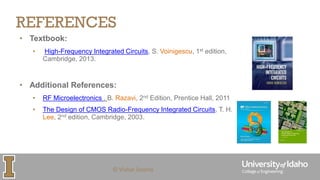
ECE 413/513 –RADIO FREQUENCY IC
DESIGN
COURSE INTRODUCTION
VISHAL SAXENA
VSAXENA@UIDAHO.EDU
© Vishal Saxena
© Vishal Saxena
COURSE OUTLINE
Course Site : http://lumerink.com/courses/ece513/f18/ECE513.htm
© Vishal Saxena
COURSE TOPICS
• Radio Frequency (RF) Transceivers: Basics and Architectures
• Fundamentals:
• Two-port networks
• Distortion and Noise
• Matching, Smith Chart use
• RF Link budget analysis
• High-frequency MOSFETs
• Tuned amplifier design and analysis
• Low-noise amplifiers (LNA)
• Mixers
• Oscillators (PLLs covered in ECE 504)
• Power Amplifiers (if time permits)
© Vishal Saxena
REFERENCES
• Textbook:
• High-Frequency Integrated Circuits, S. Voinigescu, 1st edition,
Cambridge, 2013.
• Additional References:
• RF Microelectronics , B. Razavi, 2nd Edition, Prentice Hall, 2011
• The Design of CMOS Radio-Frequency Integrated Circuits, T. H.
Lee, 2nd edition, Cambridge, 2003.
© Vishal Saxena
COURSE PEDAGOGY AND GRADING
• Combination of lecture notes and slides
▪Lecture notes to be posted online
▪Additional slides, Matlab code etc. will also be posted on the site
• Workload (Grading)
▪Homeworks (25%)
▪Midterm Exam (25%)
▪Project 1 (25%)
▪Final Exam or Project 2 (25%)
• Cadence is used for design-based HWs and Projects
© Vishal Saxena
COURSE POLICIES
• No late work
• Neither the final exam nor final project will be returned at the end
of the semester
• No internet surfing in class on any device
• Plagiarism and outsourcing (!) of work is not acceptable (See
UoI Policy).
• See detailed policies on the course site
ANALOG IC COURSES AT UI
ECE 410
- Microelectronics II
ECE 515
–Analog IC Design
ECE 517
– Mixed-Signal IC Design
ECE 513
– RF IC Design
ECE 519
– CMOS Imager Design
ECE 504
–PLL and High-speed Link Design
ECE 504-X
– Other Advanced Topics in IC Design
ECE 515
ECE 513
ECE 513
ECE 515
ECE 515
ECE 517
ECE 515
ECE 445
ECE 504
ECE 517
© Vishal Saxena
REVIEW
• Brush up on Analog Circuit Design basics (ECE 410)
• http://lumerink.com/courses/ece5411/s11/Lectures.htm
• Signals and Systems
• Frequency domain understanding, modulation and demodulation from your undergrad
textbook
• Review Smith Chart
• https://www.youtube.com/watch?v=hmqM8PnUkmo&t=380s
WIRELESS TRANSCEIVERS
• ‘Radio’ transceivers are ubiquitous and indispensable
• Cellular, internet of things, satellite, military, RADAR,………
• Recent activity in 5G wireless extended to 28GHz, 60GHz and higher frequency bands
https://pt.slideshare.net/SatyaHarish1/wearables-show-march-2015
SPECTRUM ALLOCATION
https://www.ntia.doc.gov/files/ntia/publications/january_2016_spectrum_wall_chart.pdf
RF SPECTRUM ALLOCATION
https://www.ee.washington.edu/spotlight/uw-radio-researchers-break-world-record-with-full-duplex-
communication/
RF TRANSCEIVERS
TX
Baseband
RX
Baseband
Analog
Digital Analog Digital
Power
Amp (PA)
Low Noise
Amp (LNA)
Upconversion Downconversion
Antennae
Bits in Bits out
© Vishal Saxena
ANTENNA BASICS
© Vishal Saxena
ANTENNAS
• Antennas ‘match’ the energy on a transmission
line to a propagating wave in free space (377Ω
impedance)
• Essentially a passive device with an input impedance,
efficiency, gain and directivity
• Higher gain implies higher directivity.
• Omnidirectional antenna has lower gain (think of light
bulb) than an antenna with high directivity (think of
flashlight)
• Efficient antennas have dimensions roughly equal
to the free space propagation wavelength (λ)
Ali Niknejad, “Advanced Communication Integrated Circuits” UC Berkeley, 2015.
© Vishal Saxena
FRIIS PROPAGATION EQUATION
𝑃𝑟 = 𝐺𝑡 ⋅
𝑃𝑡
4𝜋𝑟2
⋅ 𝐴𝑒𝑟
Received power
TX RX
Pt Pr
Gt Gr
𝐴𝑒𝑟 =
𝜆2
4𝜋
𝐺𝑟
Effective aperture
of the RX
𝑃𝑟
𝑃𝑡
=
𝐴𝑒1𝐴𝑒2
𝑟2𝜆2
=
𝐺𝑡𝐺𝑟
4𝜋𝑟
𝜆
2
Gt: Gain of TX antenna
Gr: Gain of RX antenna
r: Line of sight distance
TX power over surface
area of sphere
Ali Niknejad, “Advanced Communication Integrated Circuits” UC Berkeley, 2015.
© Vishal Saxena
FRIIS PROPAGATION EQUATION
Friis Calculator: https://www.pasternack.com/t-calculator-friis.aspx
𝑃
𝑟
𝑃𝑡
=
𝐺𝑡𝐺𝑟
4𝜋𝑟
𝜆
2 =
𝐺𝑡𝐺𝑟
4𝜋𝑟𝑓𝑐
𝑐
2
• For a fixed antenna gain (directivity), the attenuation increases as f2
• Capture area at RX antenna is proportional to λ2, which is decreasing with f
𝑃𝑟|𝑑𝐵 = 𝑃𝑡|𝑑𝐵 + 𝐺𝑡|𝑑𝐵 + 𝐺𝑟|𝑑𝐵 + 20 ⋅ 𝑙𝑜𝑔10
λ
4𝜋𝑟
© Vishal Saxena
FRIIS PROPAGATION EQUATION
• If we had fixed area for the antenna, the antenna gain (directivity) needs to
increase with frequency
• Realized using dish antenna or an ‘antenna array’
• More on antenna array later (Section 2.9 in the textbook)
𝑃
𝑟
𝑃𝑡
=
𝐺𝑡𝐺𝑟
4𝜋𝑟
𝜆
2 =
𝐺𝑡𝐺𝑟
4𝜋𝑟𝑓𝑐
𝑐
2
𝑃𝑟|𝑑𝐵 = 𝑃𝑡|𝑑𝐵 + 𝐺𝑡|𝑑𝐵 + 𝐺𝑟|𝑑𝐵 + 20 ⋅ 𝑙𝑜𝑔10
λ
4𝜋𝑟
© Vishal Saxena
RX POWER
• Received signal is very weak, typically -80dBm to -120dBm
• Often drowned by large interferers (say >0dBm).
Friis Calculator: https://www.pasternack.com/t-calculator-friis.aspx
RF TRANSCEIVERS
TX
Baseband
RX
Baseband
Analog
Digital Analog Digital
Power
Amp (PA)
Low Noise
Amp (LNA)
Upconversion Downconversion
Antennae
Bits in Bits out
RF TRANSCEIVERS
TX
Baseband
RX
Baseband
Analog
Digital Analog Digital
Power
Amp (PA)
Low Noise
Amp (LNA)
Upconversion Downconversion
Antennae
Bits in Bits out
f
PSD
0
f
fc
f
fc
f
0
RF TRANSCEIVERS
f
PSD
0
f
fc
f
0
f
fc
Blocker or
Interferer
f
fc
TX
Baseband
RX
Baseband
Analog
Digital Analog Digital
PA LNA
Upconversion Downconversion
Antennae
Bits in Bits out
BSF
© Vishal Saxena
RADIO TRANSCEIVERS
• A transmitter modulates a baseband signal to a higher carrier
frequency and feeds and antenna with sufficient power
• Should not distort the TX signal too much
• A well-designed receiver should perform
• High-gain amplification of the received signal
• Highly selective filtering of the desired signal
• Reject adjacent channels, interferers, and image signal
• Recovery of the intended information within error limits
• Processing narrowband analog signals with high selectivity and
dynamic range
f
fc
© Vishal Saxena
RADIO TRANSCEIVERS: ISOLATION
• Usually TX and RX don’t operate simultaneously at the same
carrier frequency
• Frequency-division multiplexing (FDD) or
• Time-division multiplexing (TDD) schemes used
• Other methods of isolation
• Selectivity achieved using off-chip filters (SAW or MEMS)
• Isolation between TX and RX achieved using off-chip diplexers
and isolators/circulators
© Vishal Saxena
RF TX/RX ISOLATION
• Isolation usually not sufficient for simultaneous TX and RX
• TX leaks to RX through package coupling and reflections
• Search full-duplex radios online for recent advances!
PA
t
LNA SAW Filter
T/R
Switch
T R T R
f
fc
PA
LNA
TX
Diplexer
t
T
R
f
fc1 fc2
RX T R T R
PA
LNA Circulator
t
TR
f
fc
1
2
3
R T R
COMMERCIAL RFICS
Qualcomm RTR8600 chip
Multi-band Multi-mode RF transceiver found in prominent
Smartphones
BCM 4330 – Mobile Wireless
Single-band 2.4 GHz 802.11 b/g/n or dual-band 2.4 GHz and 5Ghz
802.11 a/b/g/n Integrated ARM® Cortex™-M3 processor and on-chip
memory.

lec1_ece513_slides.pdf

  • 1.
    ECE 413/513 –RADIOFREQUENCY IC DESIGN COURSE INTRODUCTION VISHAL SAXENA VSAXENA@UIDAHO.EDU © Vishal Saxena
  • 2.
    © Vishal Saxena COURSEOUTLINE Course Site : http://lumerink.com/courses/ece513/f18/ECE513.htm
  • 3.
    © Vishal Saxena COURSETOPICS • Radio Frequency (RF) Transceivers: Basics and Architectures • Fundamentals: • Two-port networks • Distortion and Noise • Matching, Smith Chart use • RF Link budget analysis • High-frequency MOSFETs • Tuned amplifier design and analysis • Low-noise amplifiers (LNA) • Mixers • Oscillators (PLLs covered in ECE 504) • Power Amplifiers (if time permits)
  • 4.
    © Vishal Saxena REFERENCES •Textbook: • High-Frequency Integrated Circuits, S. Voinigescu, 1st edition, Cambridge, 2013. • Additional References: • RF Microelectronics , B. Razavi, 2nd Edition, Prentice Hall, 2011 • The Design of CMOS Radio-Frequency Integrated Circuits, T. H. Lee, 2nd edition, Cambridge, 2003.
  • 5.
    © Vishal Saxena COURSEPEDAGOGY AND GRADING • Combination of lecture notes and slides ▪Lecture notes to be posted online ▪Additional slides, Matlab code etc. will also be posted on the site • Workload (Grading) ▪Homeworks (25%) ▪Midterm Exam (25%) ▪Project 1 (25%) ▪Final Exam or Project 2 (25%) • Cadence is used for design-based HWs and Projects
  • 6.
    © Vishal Saxena COURSEPOLICIES • No late work • Neither the final exam nor final project will be returned at the end of the semester • No internet surfing in class on any device • Plagiarism and outsourcing (!) of work is not acceptable (See UoI Policy). • See detailed policies on the course site
  • 7.
    ANALOG IC COURSESAT UI ECE 410 - Microelectronics II ECE 515 –Analog IC Design ECE 517 – Mixed-Signal IC Design ECE 513 – RF IC Design ECE 519 – CMOS Imager Design ECE 504 –PLL and High-speed Link Design ECE 504-X – Other Advanced Topics in IC Design ECE 515 ECE 513 ECE 513 ECE 515 ECE 515 ECE 517 ECE 515 ECE 445 ECE 504 ECE 517
  • 8.
    © Vishal Saxena REVIEW •Brush up on Analog Circuit Design basics (ECE 410) • http://lumerink.com/courses/ece5411/s11/Lectures.htm • Signals and Systems • Frequency domain understanding, modulation and demodulation from your undergrad textbook • Review Smith Chart • https://www.youtube.com/watch?v=hmqM8PnUkmo&t=380s
  • 9.
    WIRELESS TRANSCEIVERS • ‘Radio’transceivers are ubiquitous and indispensable • Cellular, internet of things, satellite, military, RADAR,……… • Recent activity in 5G wireless extended to 28GHz, 60GHz and higher frequency bands https://pt.slideshare.net/SatyaHarish1/wearables-show-march-2015
  • 10.
  • 11.
  • 12.
    RF TRANSCEIVERS TX Baseband RX Baseband Analog Digital AnalogDigital Power Amp (PA) Low Noise Amp (LNA) Upconversion Downconversion Antennae Bits in Bits out
  • 13.
  • 14.
    © Vishal Saxena ANTENNAS •Antennas ‘match’ the energy on a transmission line to a propagating wave in free space (377Ω impedance) • Essentially a passive device with an input impedance, efficiency, gain and directivity • Higher gain implies higher directivity. • Omnidirectional antenna has lower gain (think of light bulb) than an antenna with high directivity (think of flashlight) • Efficient antennas have dimensions roughly equal to the free space propagation wavelength (λ) Ali Niknejad, “Advanced Communication Integrated Circuits” UC Berkeley, 2015.
  • 15.
    © Vishal Saxena FRIISPROPAGATION EQUATION 𝑃𝑟 = 𝐺𝑡 ⋅ 𝑃𝑡 4𝜋𝑟2 ⋅ 𝐴𝑒𝑟 Received power TX RX Pt Pr Gt Gr 𝐴𝑒𝑟 = 𝜆2 4𝜋 𝐺𝑟 Effective aperture of the RX 𝑃𝑟 𝑃𝑡 = 𝐴𝑒1𝐴𝑒2 𝑟2𝜆2 = 𝐺𝑡𝐺𝑟 4𝜋𝑟 𝜆 2 Gt: Gain of TX antenna Gr: Gain of RX antenna r: Line of sight distance TX power over surface area of sphere Ali Niknejad, “Advanced Communication Integrated Circuits” UC Berkeley, 2015.
  • 16.
    © Vishal Saxena FRIISPROPAGATION EQUATION Friis Calculator: https://www.pasternack.com/t-calculator-friis.aspx 𝑃 𝑟 𝑃𝑡 = 𝐺𝑡𝐺𝑟 4𝜋𝑟 𝜆 2 = 𝐺𝑡𝐺𝑟 4𝜋𝑟𝑓𝑐 𝑐 2 • For a fixed antenna gain (directivity), the attenuation increases as f2 • Capture area at RX antenna is proportional to λ2, which is decreasing with f 𝑃𝑟|𝑑𝐵 = 𝑃𝑡|𝑑𝐵 + 𝐺𝑡|𝑑𝐵 + 𝐺𝑟|𝑑𝐵 + 20 ⋅ 𝑙𝑜𝑔10 λ 4𝜋𝑟
  • 17.
    © Vishal Saxena FRIISPROPAGATION EQUATION • If we had fixed area for the antenna, the antenna gain (directivity) needs to increase with frequency • Realized using dish antenna or an ‘antenna array’ • More on antenna array later (Section 2.9 in the textbook) 𝑃 𝑟 𝑃𝑡 = 𝐺𝑡𝐺𝑟 4𝜋𝑟 𝜆 2 = 𝐺𝑡𝐺𝑟 4𝜋𝑟𝑓𝑐 𝑐 2 𝑃𝑟|𝑑𝐵 = 𝑃𝑡|𝑑𝐵 + 𝐺𝑡|𝑑𝐵 + 𝐺𝑟|𝑑𝐵 + 20 ⋅ 𝑙𝑜𝑔10 λ 4𝜋𝑟
  • 18.
    © Vishal Saxena RXPOWER • Received signal is very weak, typically -80dBm to -120dBm • Often drowned by large interferers (say >0dBm). Friis Calculator: https://www.pasternack.com/t-calculator-friis.aspx
  • 19.
    RF TRANSCEIVERS TX Baseband RX Baseband Analog Digital AnalogDigital Power Amp (PA) Low Noise Amp (LNA) Upconversion Downconversion Antennae Bits in Bits out
  • 20.
    RF TRANSCEIVERS TX Baseband RX Baseband Analog Digital AnalogDigital Power Amp (PA) Low Noise Amp (LNA) Upconversion Downconversion Antennae Bits in Bits out f PSD 0 f fc f fc f 0
  • 21.
    RF TRANSCEIVERS f PSD 0 f fc f 0 f fc Blocker or Interferer f fc TX Baseband RX Baseband Analog DigitalAnalog Digital PA LNA Upconversion Downconversion Antennae Bits in Bits out BSF
  • 22.
    © Vishal Saxena RADIOTRANSCEIVERS • A transmitter modulates a baseband signal to a higher carrier frequency and feeds and antenna with sufficient power • Should not distort the TX signal too much • A well-designed receiver should perform • High-gain amplification of the received signal • Highly selective filtering of the desired signal • Reject adjacent channels, interferers, and image signal • Recovery of the intended information within error limits • Processing narrowband analog signals with high selectivity and dynamic range f fc
  • 23.
    © Vishal Saxena RADIOTRANSCEIVERS: ISOLATION • Usually TX and RX don’t operate simultaneously at the same carrier frequency • Frequency-division multiplexing (FDD) or • Time-division multiplexing (TDD) schemes used • Other methods of isolation • Selectivity achieved using off-chip filters (SAW or MEMS) • Isolation between TX and RX achieved using off-chip diplexers and isolators/circulators
  • 24.
    © Vishal Saxena RFTX/RX ISOLATION • Isolation usually not sufficient for simultaneous TX and RX • TX leaks to RX through package coupling and reflections • Search full-duplex radios online for recent advances! PA t LNA SAW Filter T/R Switch T R T R f fc PA LNA TX Diplexer t T R f fc1 fc2 RX T R T R PA LNA Circulator t TR f fc 1 2 3 R T R
  • 25.
    COMMERCIAL RFICS Qualcomm RTR8600chip Multi-band Multi-mode RF transceiver found in prominent Smartphones BCM 4330 – Mobile Wireless Single-band 2.4 GHz 802.11 b/g/n or dual-band 2.4 GHz and 5Ghz 802.11 a/b/g/n Integrated ARM® Cortex™-M3 processor and on-chip memory.