Fair Use Notice:
Thematerial used in this presentation i.e., pictures/graphs/text, etc. is
solely intended for educational/teaching purpose, offered free of cost to
the students for use under special circumstances of Online Education
due to COVID-19 Lockdown situation and may include copyrighted
material - the use of which may not have been specifically authorised
by Copyright Owners. It’s application constitutes Fair Use of any such
copyrighted material as provided in globally accepted law of many
countries. The contents of presentations are intended only for the
attendees of the class being conducted by the presenter.
1
DATABASE MODELS
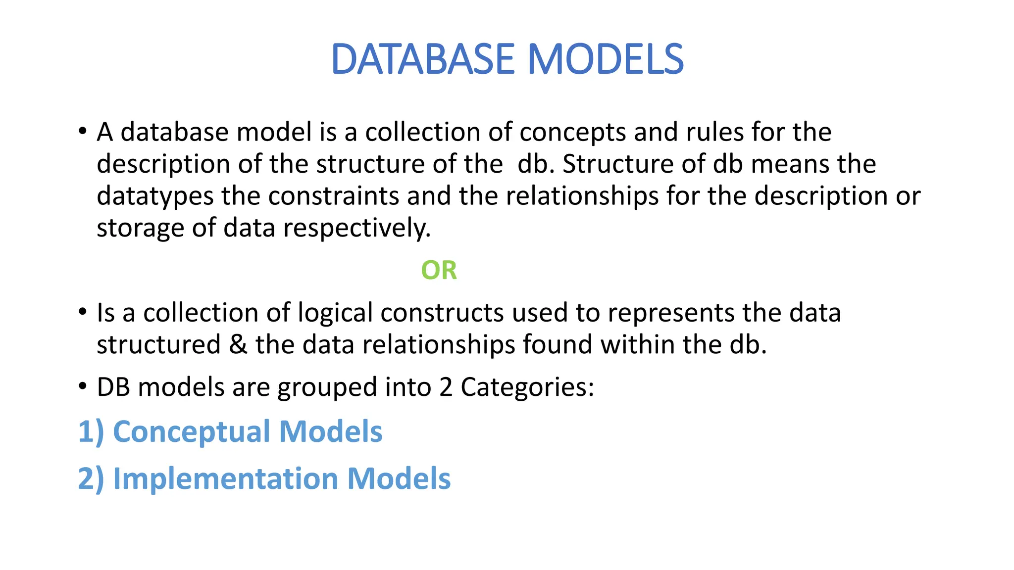
• Adatabase model is a collection of concepts and rules for the
description of the structure of the db. Structure of db means the
datatypes the constraints and the relationships for the description or
storage of data respectively.
OR
• Is a collection of logical constructs used to represents the data
structured & the data relationships found within the db.
• DB models are grouped into 2 Categories:
1) Conceptual Models
2) Implementation Models
4.
CONCEPTUAL MODELS
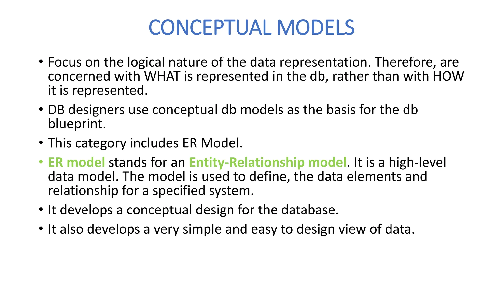
• Focuson the logical nature of the data representation. Therefore, are
concerned with WHAT is represented in the db, rather than with HOW
it is represented.
• DB designers use conceptual db models as the basis for the db
blueprint.
• This category includes ER Model.
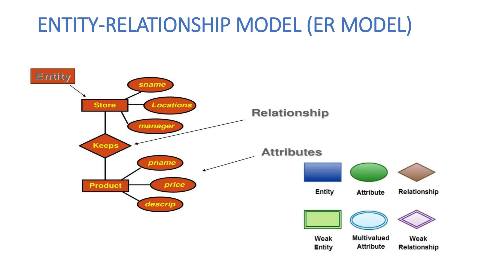
• ER model stands for an Entity-Relationship model. It is a high-level
data model. The model is used to define, the data elements and
relationship for a specified system.
• It develops a conceptual design for the database.
• It also develops a very simple and easy to design view of data.
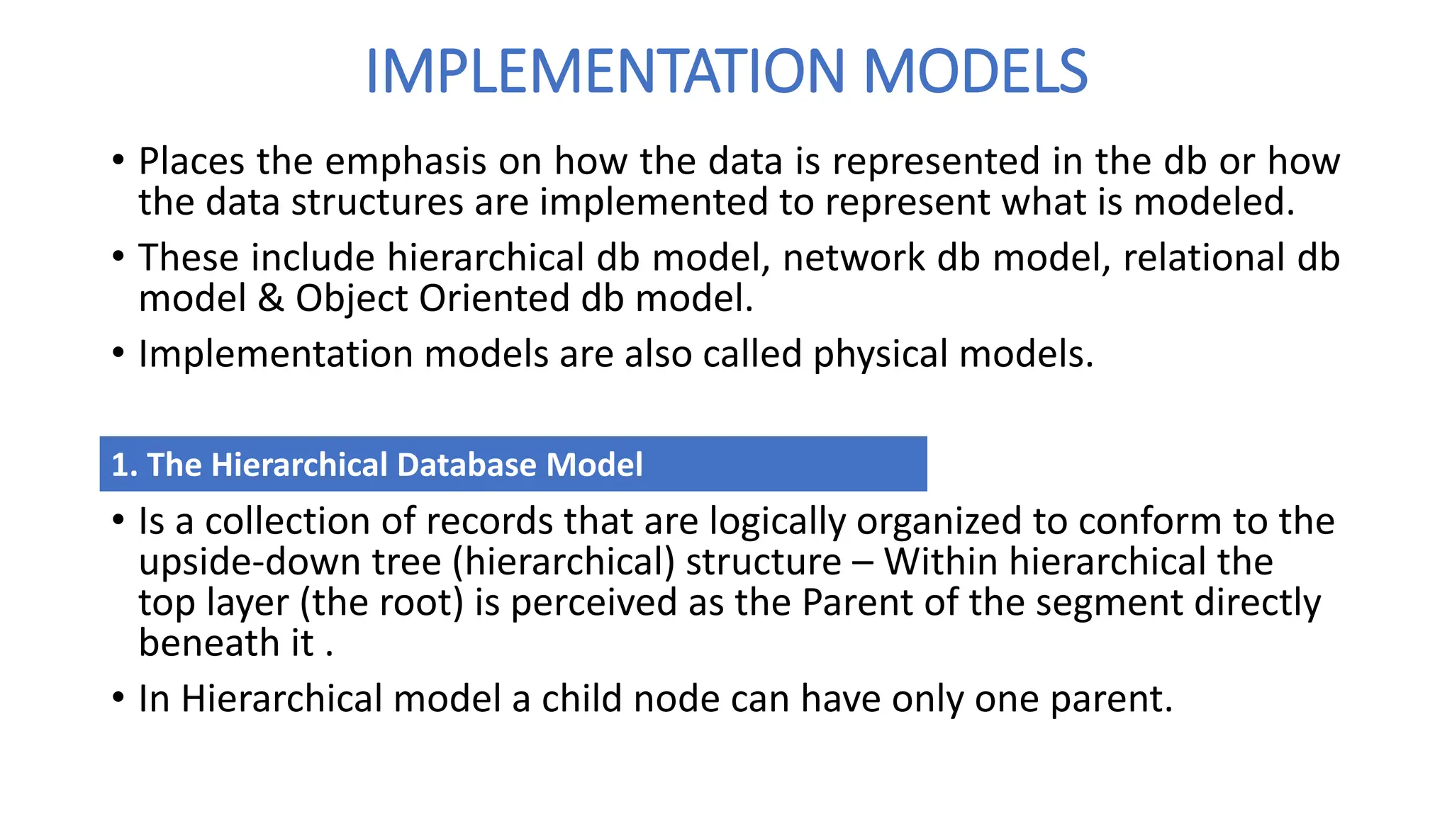
IMPLEMENTATION MODELS
• Placesthe emphasis on how the data is represented in the db or how
the data structures are implemented to represent what is modeled.
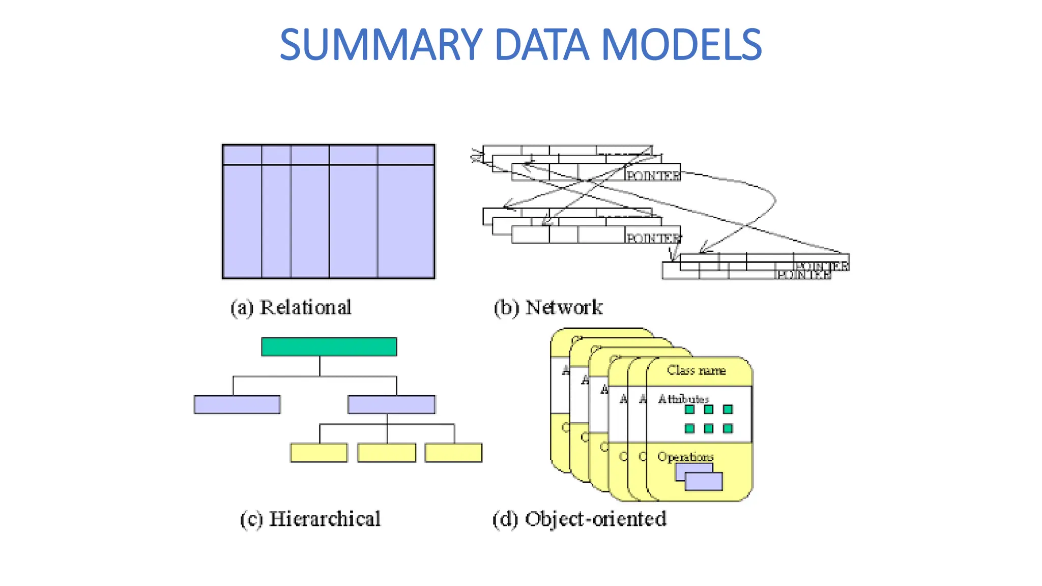
• These include hierarchical db model, network db model, relational db
model & Object Oriented db model.
• Implementation models are also called physical models.
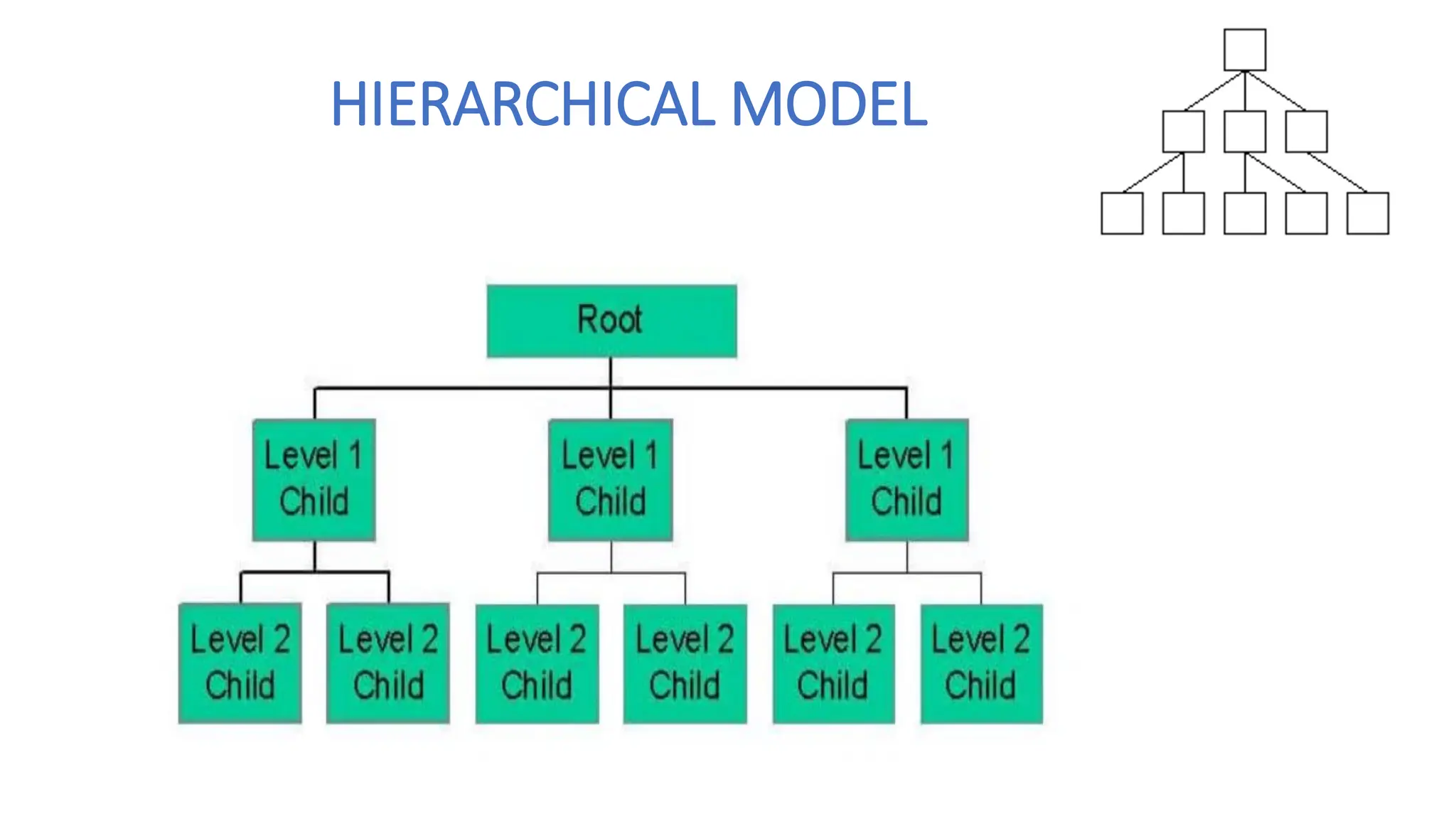
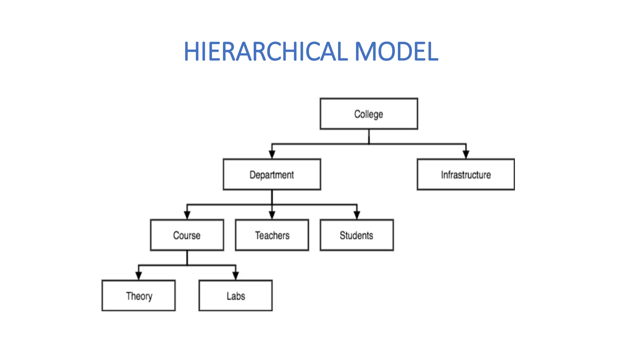
• Is a collection of records that are logically organized to conform to the
upside-down tree (hierarchical) structure – Within hierarchical the
top layer (the root) is perceived as the Parent of the segment directly
beneath it .
• In Hierarchical model a child node can have only one parent.
1. The Hierarchical Database Model
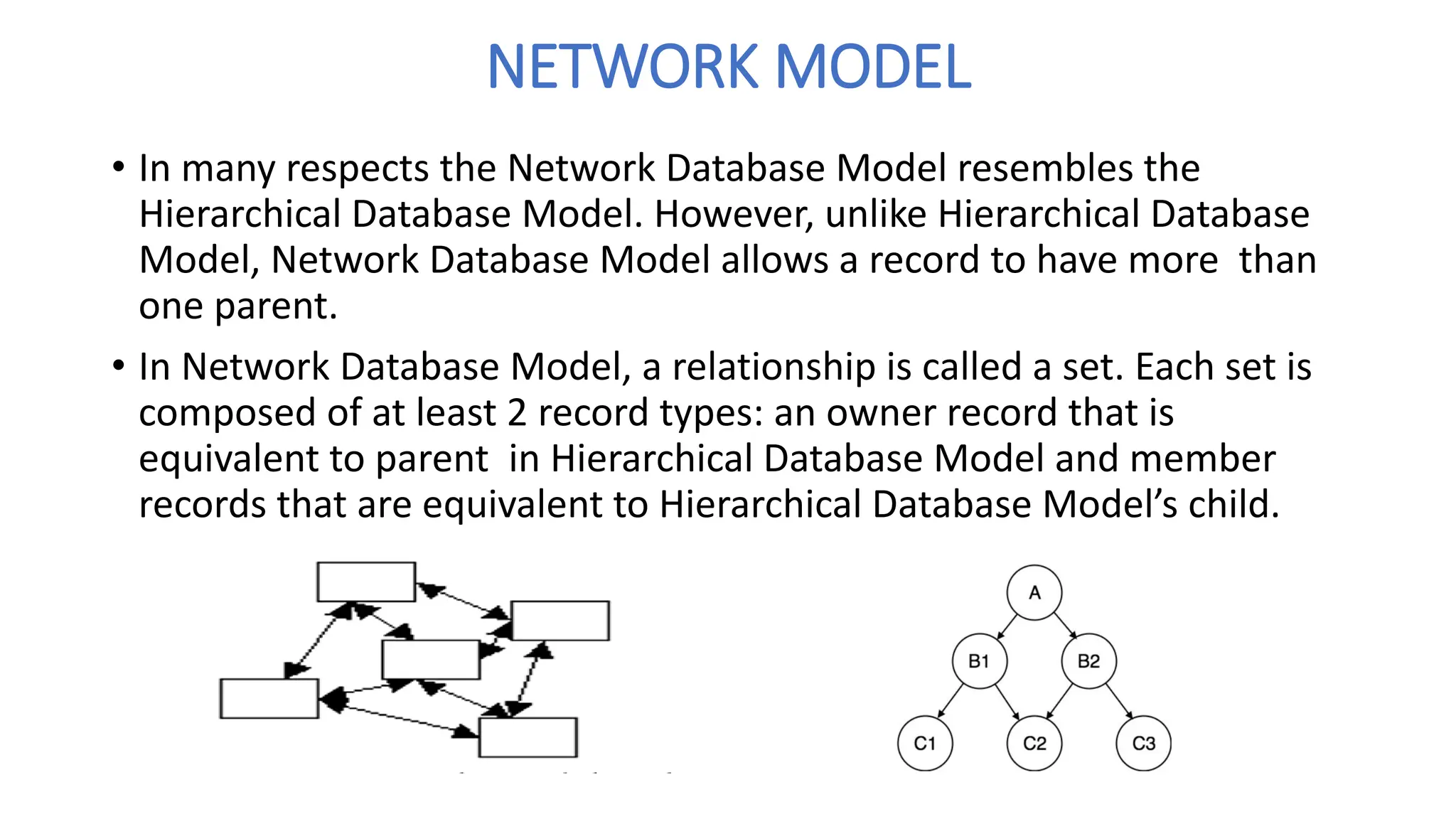
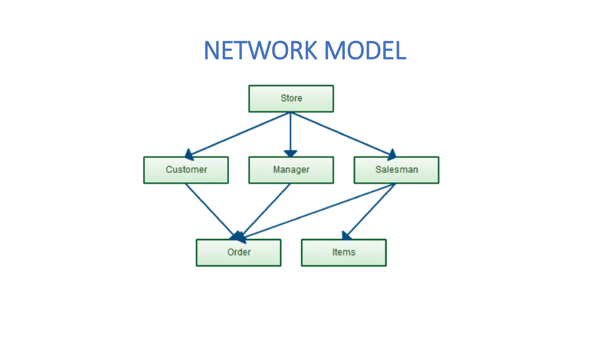
NETWORK MODEL
• Inmany respects the Network Database Model resembles the
Hierarchical Database Model. However, unlike Hierarchical Database
Model, Network Database Model allows a record to have more than
one parent.
• In Network Database Model, a relationship is called a set. Each set is
composed of at least 2 record types: an owner record that is
equivalent to parent in Hierarchical Database Model and member
records that are equivalent to Hierarchical Database Model’s child.
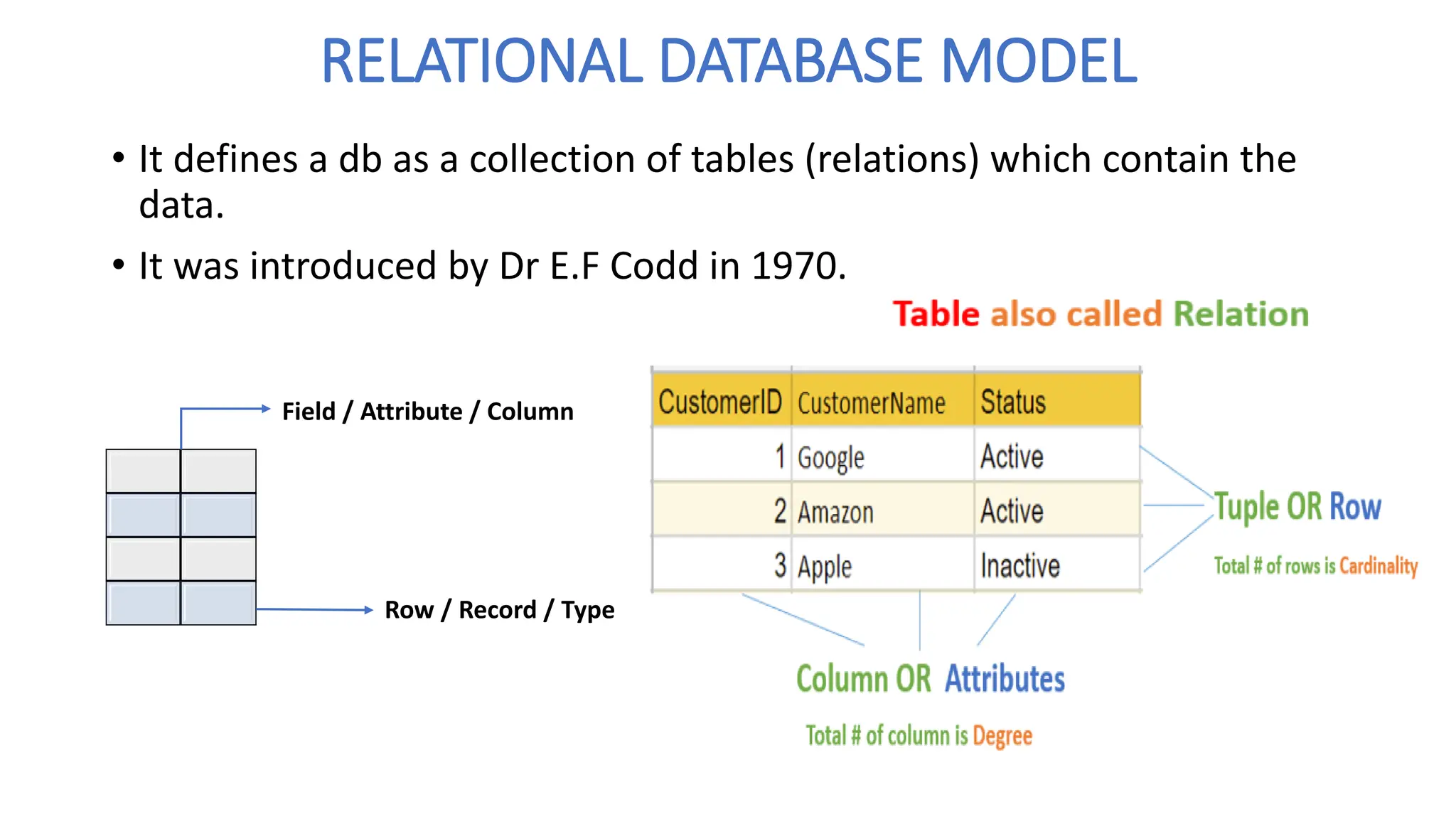
RELATIONAL DATABASE MODEL
•It defines a db as a collection of tables (relations) which contain the
data.
• It was introduced by Dr E.F Codd in 1970.
Field / Attribute / Column
Row / Record / Type
12.
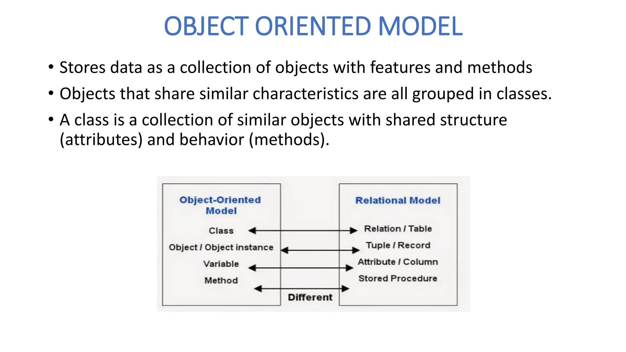
OBJECT ORIENTED MODEL
•Stores data as a collection of objects with features and methods
• Objects that share similar characteristics are all grouped in classes.
• A class is a collection of similar objects with shared structure
(attributes) and behavior (methods).
DATABASE SCHEMAS ANDDATABASE
INSTANCES
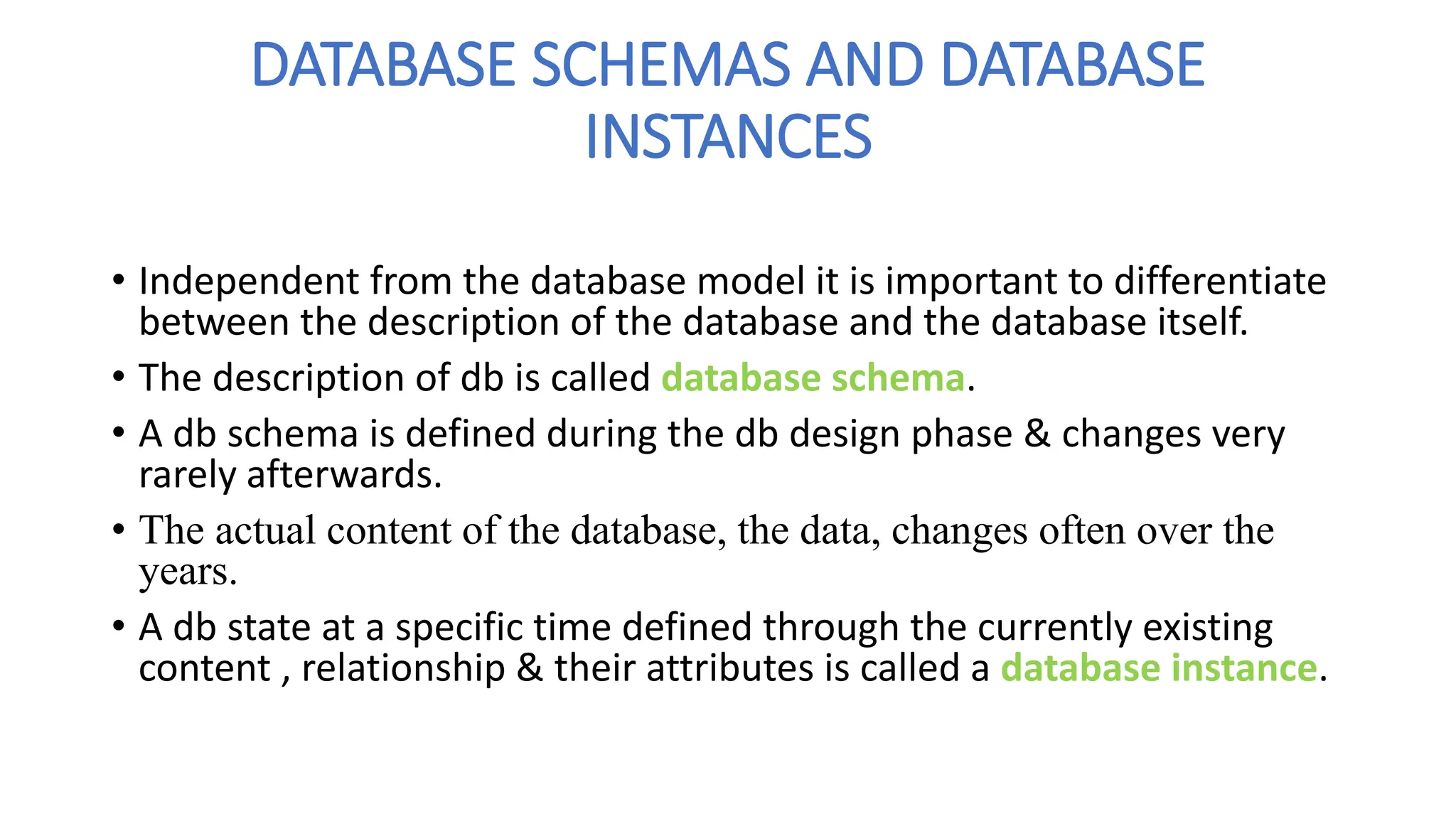
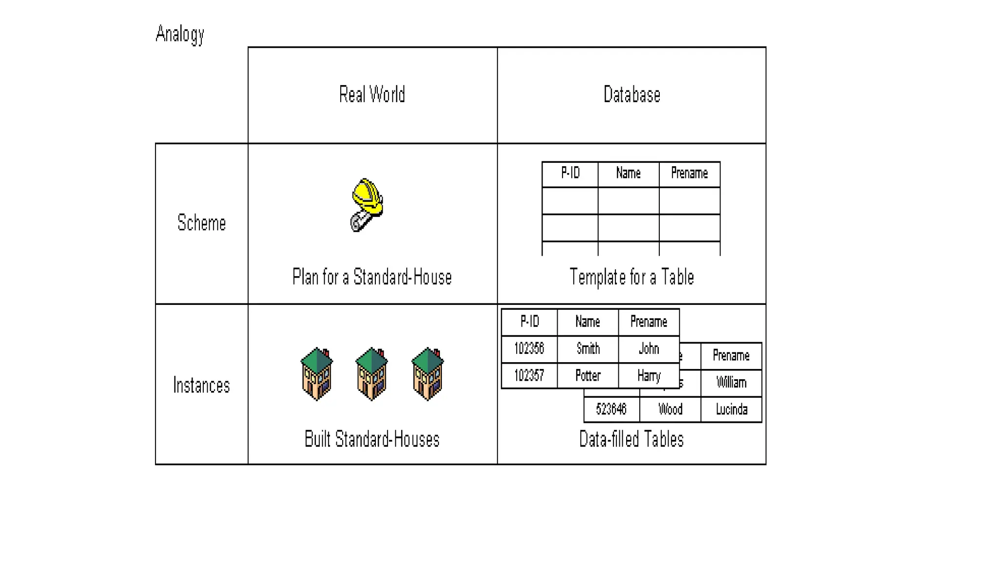
• Independent from the database model it is important to differentiate
between the description of the database and the database itself.
• The description of db is called database schema.
• A db schema is defined during the db design phase & changes very
rarely afterwards.
• The actual content of the database, the data, changes often over the
years.
• A db state at a specific time defined through the currently existing
content , relationship & their attributes is called a database instance.
16.
DATABASE MODELS
• Basedon level of abstraction, there are 3 levels of DB models
1. CONCEPTUAL DATABASE MODEL.
2. LOGICAL DATABASE MODEL.
3. PHYSICAL DATABASE MODEL.
17.
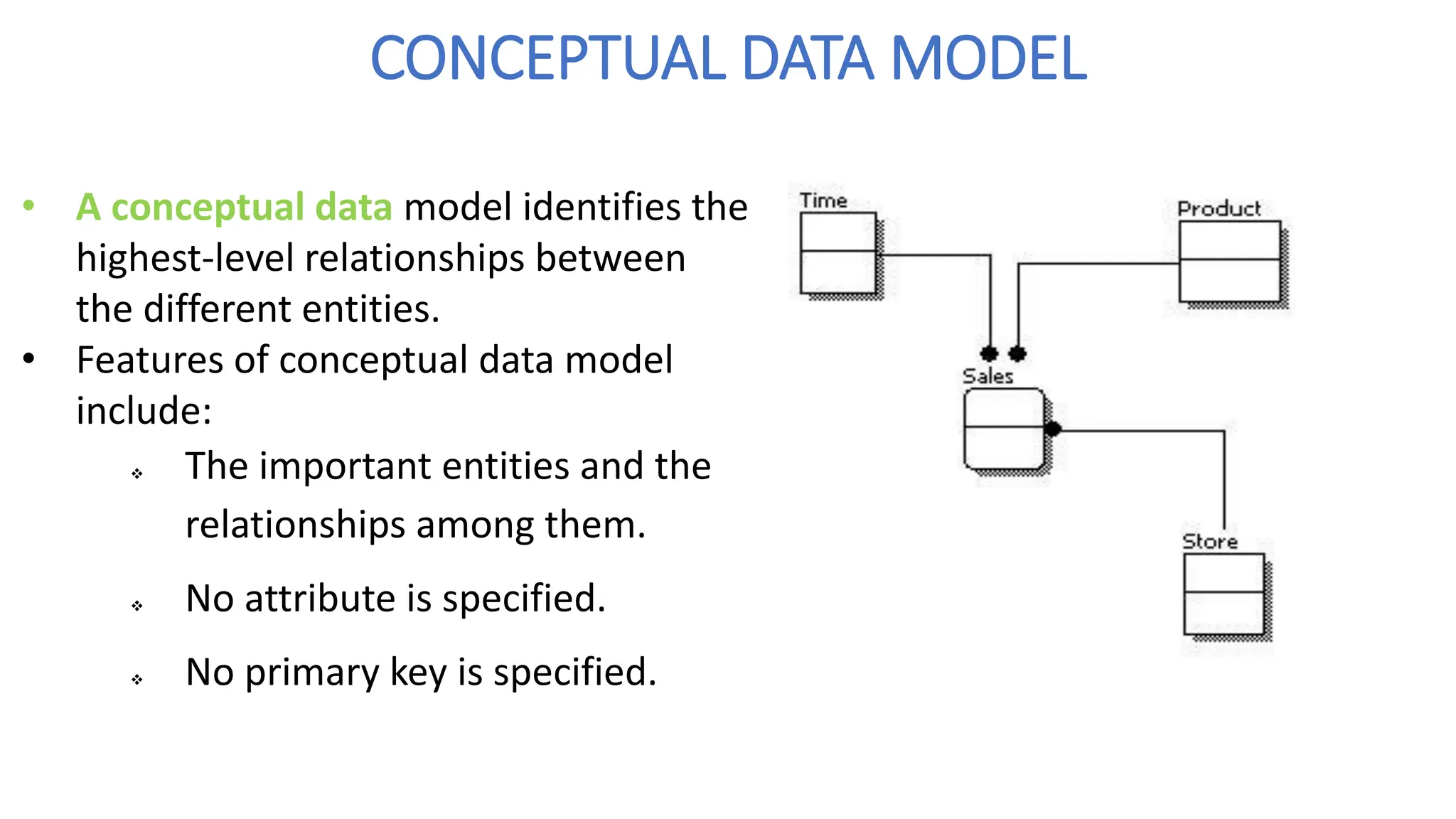
CONCEPTUAL DATA MODEL
•A conceptual data model identifies the
highest-level relationships between
the different entities.
• Features of conceptual data model
include:
❖ The important entities and the
relationships among them.
❖ No attribute is specified.
❖ No primary key is specified.
18.
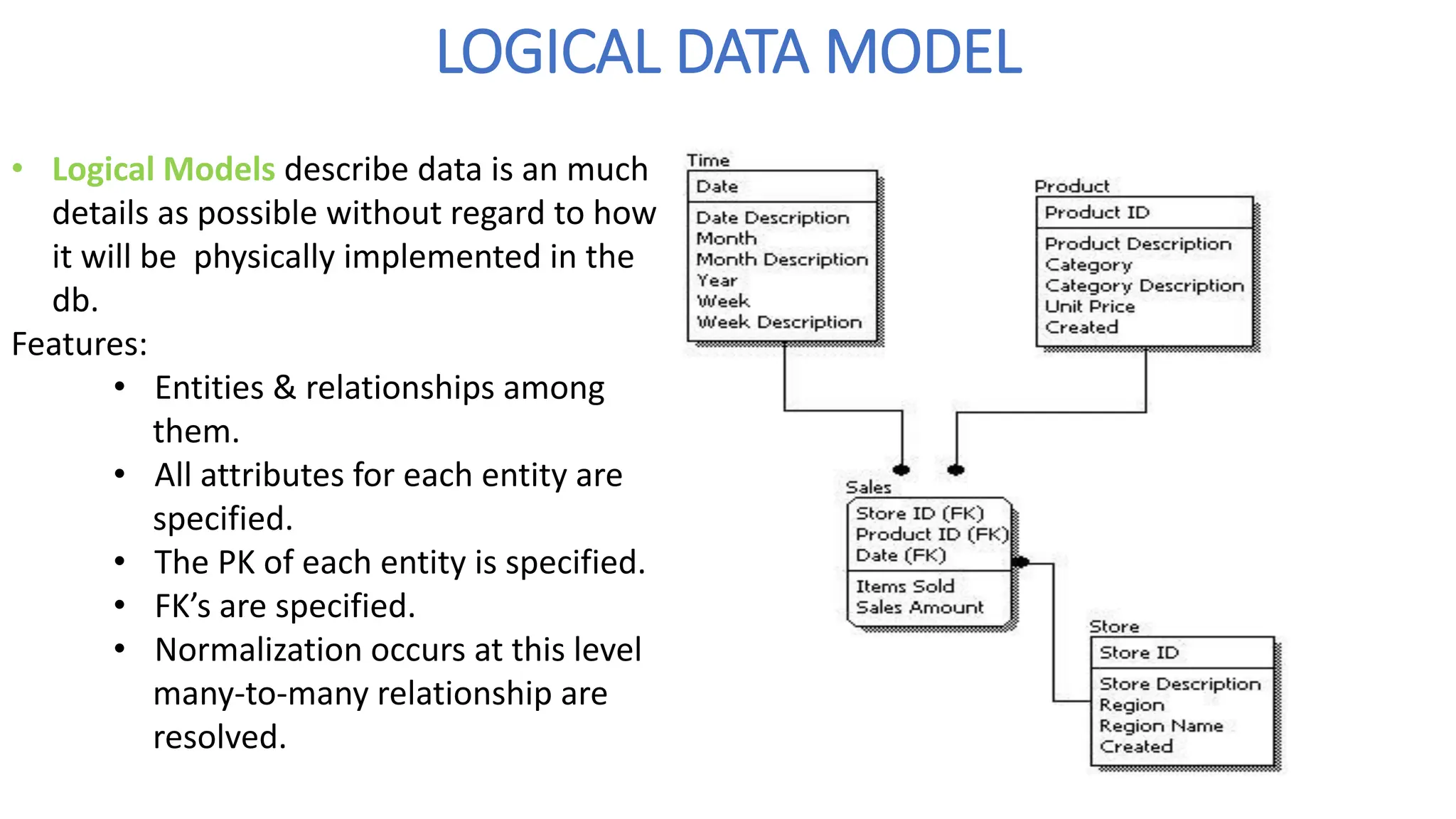
LOGICAL DATA MODEL
•Logical Models describe data is an much
details as possible without regard to how
it will be physically implemented in the
db.
Features:
• Entities & relationships among
them.
• All attributes for each entity are
specified.
• The PK of each entity is specified.
• FK’s are specified.
• Normalization occurs at this level
many-to-many relationship are
resolved.
19.
The steps fordesigning the logical data model are as follows:
1. Specify primary keys for all entities.
2. Find the relationships between different entities.
3. Find all attributes for each entity.
4. Resolve many-to-many relationships.
5. Normalization.
20.
COMPARISION BETWEEN CONCEPTUAL&
LOGICAL MODEL
• Comparing the logical data model with the conceptual data model , we see the
main differences between the two:
❖ In a logical data model, primary keys are present, whereas in a conceptual data model, no
primary key is present.
❖ In a logical data model, all attributes are specified within an entity. No attributes are
specified in a conceptual data model.
❖ Relationships between entities are specified using primary keys and foreign keys in a logical
data model. In a conceptual data model, the relationships are simply stated, not specified, so
we simply know that two entities are related, but we do not specify what attributes are used
for this relationship.
21.
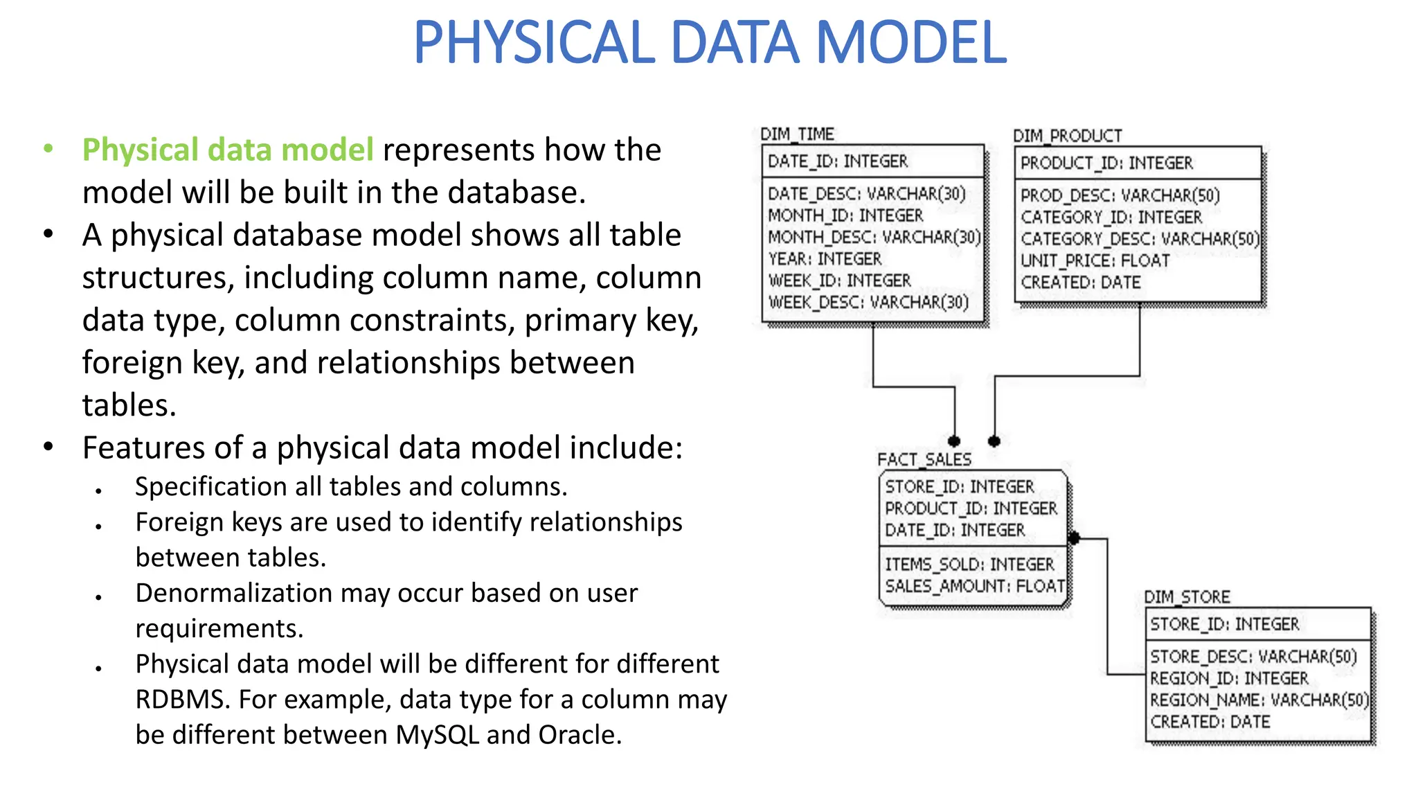
PHYSICAL DATA MODEL
•Physical data model represents how the
model will be built in the database.
• A physical database model shows all table
structures, including column name, column
data type, column constraints, primary key,
foreign key, and relationships between
tables.
• Features of a physical data model include:
• Specification all tables and columns.
• Foreign keys are used to identify relationships
between tables.
• Denormalization may occur based on user
requirements.
• Physical data model will be different for different
RDBMS. For example, data type for a column may
be different between MySQL and Oracle.
22.
• The stepsfor physical data model design are as follows:
1. Convert entities into tables.
2. Convert relationships into foreign keys.
3. Convert attributes into columns.
4. Modify the physical data model based on physical constraints / requirements.
23.
COMPARISION BETWEEN LOGICAL& PHYSICAL
MODEL
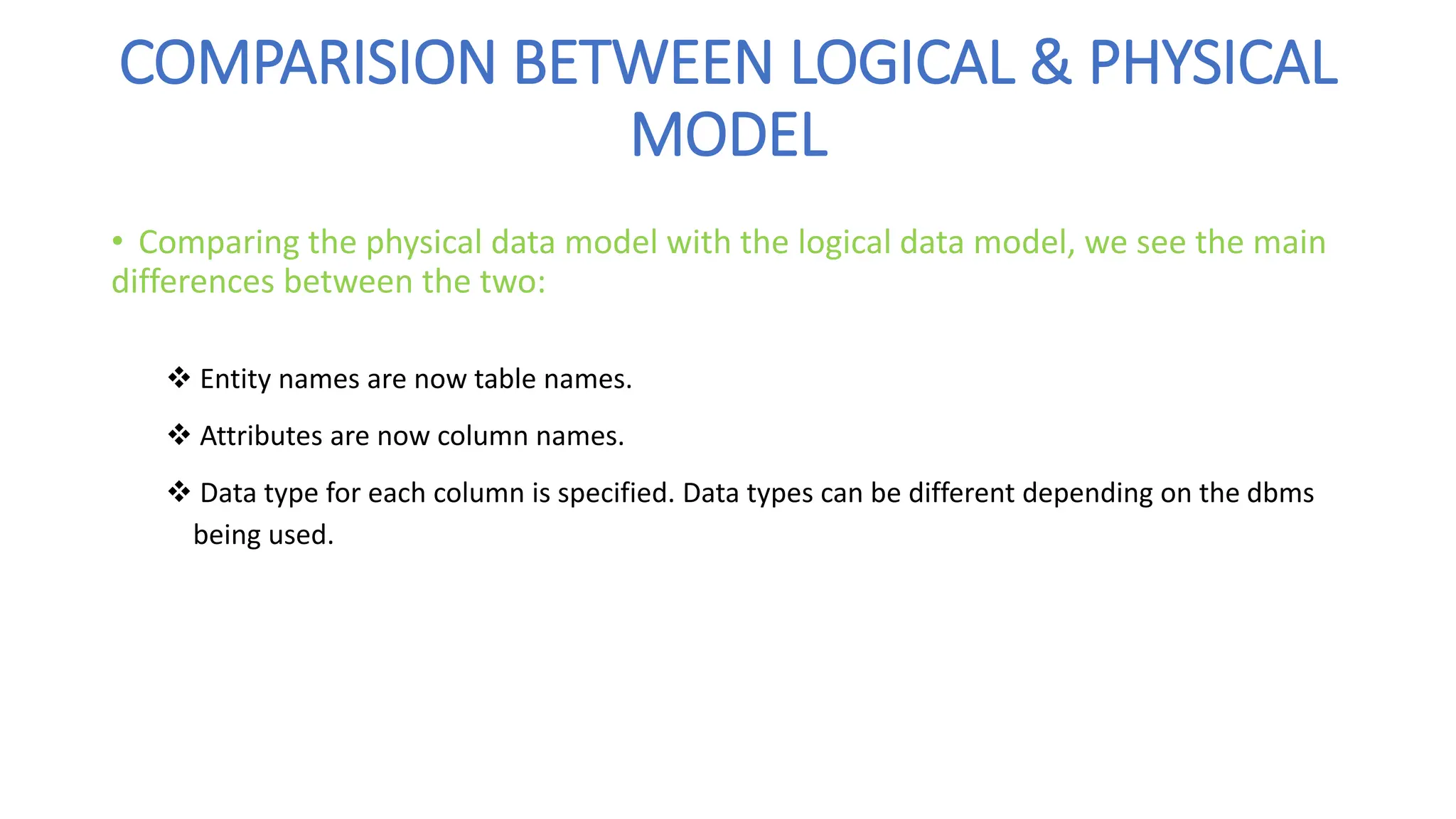
• Comparing the physical data model with the logical data model, we see the main
differences between the two:
❖ Entity names are now table names.
❖ Attributes are now column names.
❖ Data type for each column is specified. Data types can be different depending on the dbms
being used.
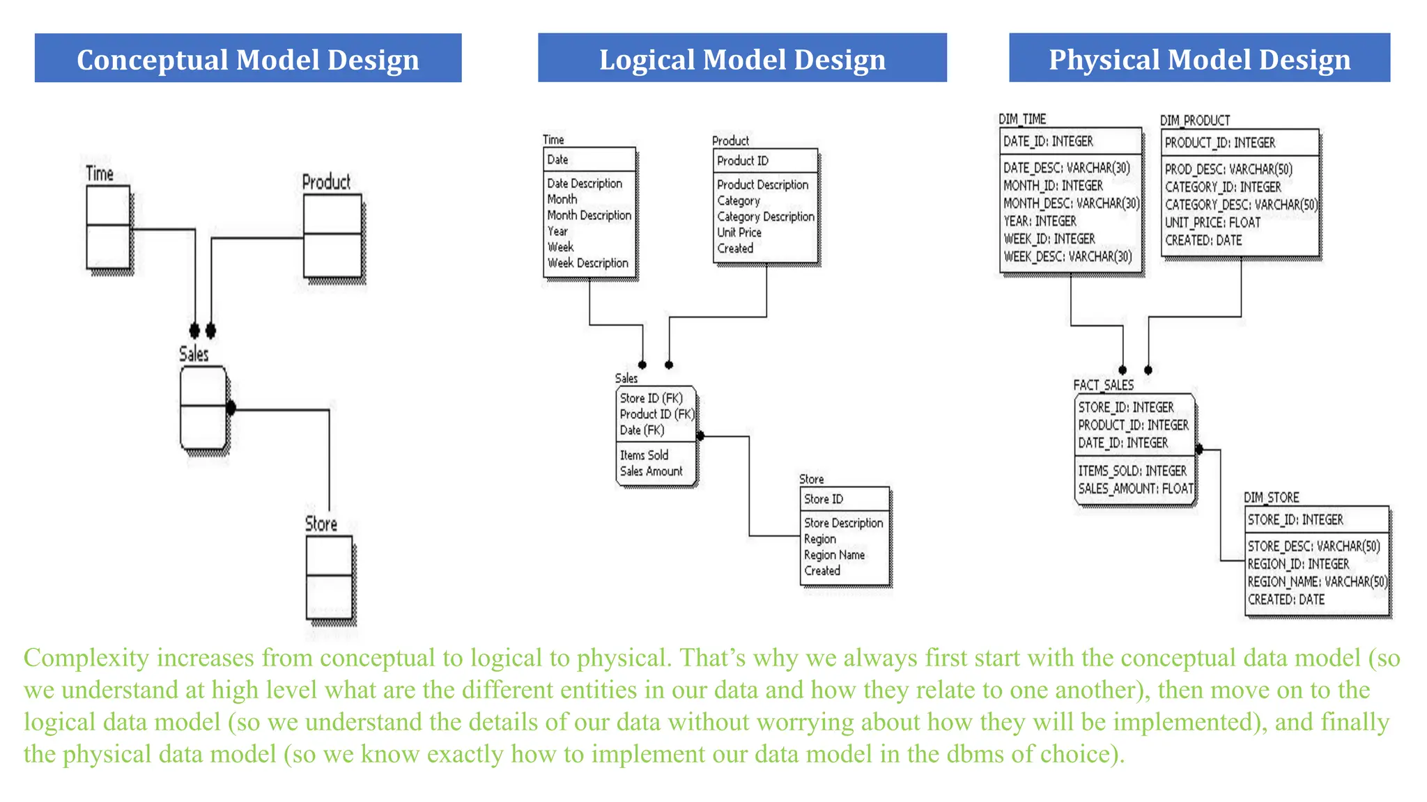
Logical Model Design
ConceptualModel Design Physical Model Design
Complexity increases from conceptual to logical to physical. That’s why we always first start with the conceptual data model (so
we understand at high level what are the different entities in our data and how they relate to one another), then move on to the
logical data model (so we understand the details of our data without worrying about how they will be implemented), and finally
the physical data model (so we know exactly how to implement our data model in the dbms of choice).
26.
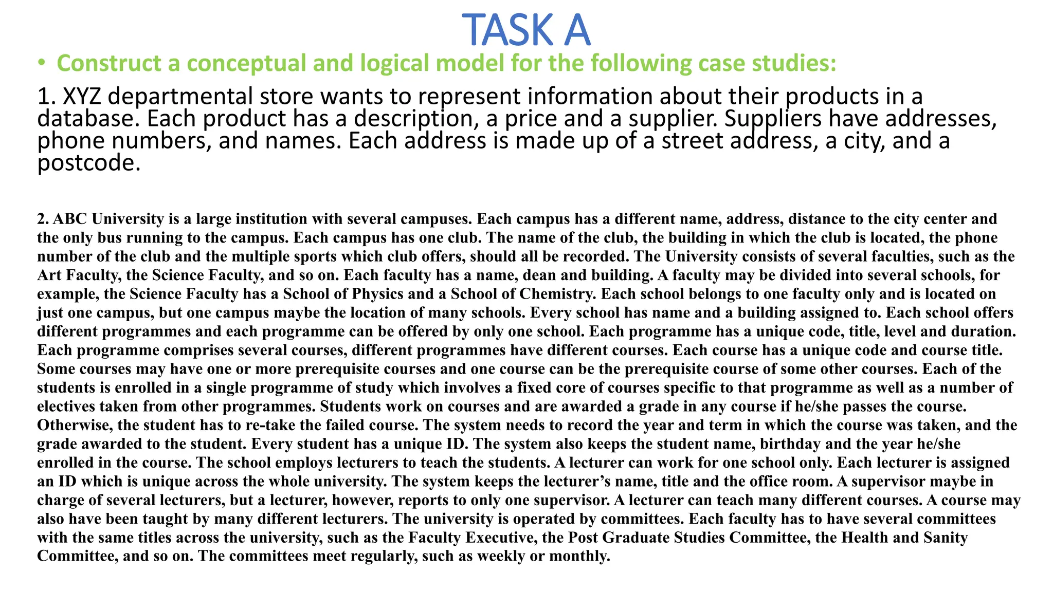
TASK A
• Constructa conceptual and logical model for the following case studies:
1. XYZ departmental store wants to represent information about their products in a
database. Each product has a description, a price and a supplier. Suppliers have addresses,
phone numbers, and names. Each address is made up of a street address, a city, and a
postcode.
2. ABC University is a large institution with several campuses. Each campus has a different name, address, distance to the city center and
the only bus running to the campus. Each campus has one club. The name of the club, the building in which the club is located, the phone
number of the club and the multiple sports which club offers, should all be recorded. The University consists of several faculties, such as the
Art Faculty, the Science Faculty, and so on. Each faculty has a name, dean and building. A faculty may be divided into several schools, for
example, the Science Faculty has a School of Physics and a School of Chemistry. Each school belongs to one faculty only and is located on
just one campus, but one campus maybe the location of many schools. Every school has name and a building assigned to. Each school offers
different programmes and each programme can be offered by only one school. Each programme has a unique code, title, level and duration.
Each programme comprises several courses, different programmes have different courses. Each course has a unique code and course title.
Some courses may have one or more prerequisite courses and one course can be the prerequisite course of some other courses. Each of the
students is enrolled in a single programme of study which involves a fixed core of courses specific to that programme as well as a number of
electives taken from other programmes. Students work on courses and are awarded a grade in any course if he/she passes the course.
Otherwise, the student has to re-take the failed course. The system needs to record the year and term in which the course was taken, and the
grade awarded to the student. Every student has a unique ID. The system also keeps the student name, birthday and the year he/she
enrolled in the course. The school employs lecturers to teach the students. A lecturer can work for one school only. Each lecturer is assigned
an ID which is unique across the whole university. The system keeps the lecturer’s name, title and the office room. A supervisor maybe in
charge of several lecturers, but a lecturer, however, reports to only one supervisor. A lecturer can teach many different courses. A course may
also have been taught by many different lecturers. The university is operated by committees. Each faculty has to have several committees
with the same titles across the university, such as the Faculty Executive, the Post Graduate Studies Committee, the Health and Sanity
Committee, and so on. The committees meet regularly, such as weekly or monthly.


![chapter 2-DATABASE SYSTEM CONCEPTS AND architecture [Autosaved].pdf](https://cdn.slidesharecdn.com/ss_thumbnails/chapter2-databasesystemconceptsandarchitectureautosaved-230512145134-613f7180-thumbnail.jpg?width=640&height=640&fit=bounds)


