Downloaded 919 times

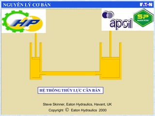


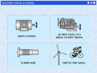
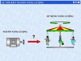
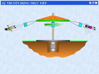
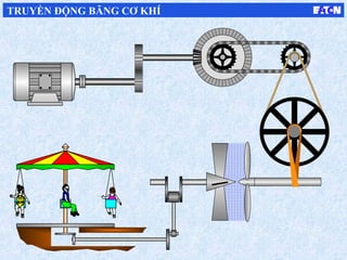
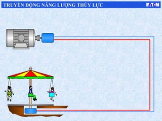
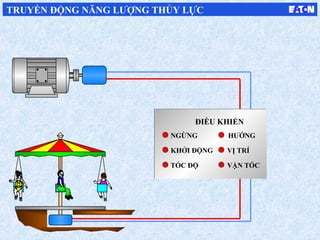
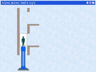
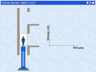
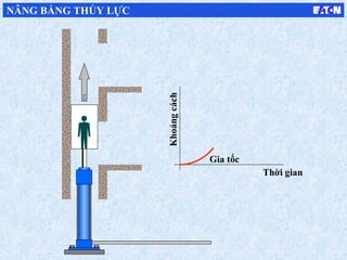
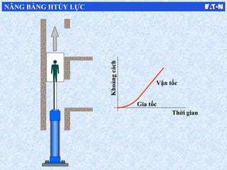
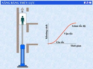
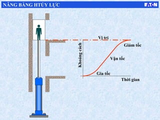


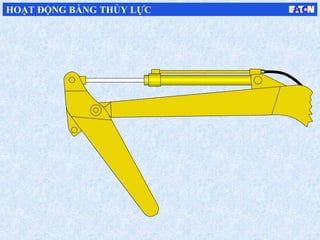

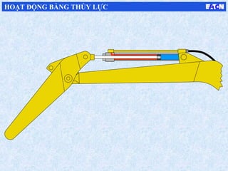


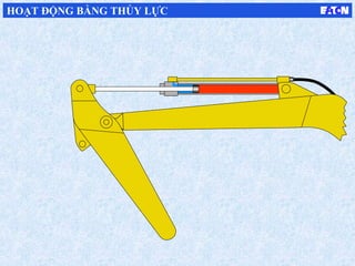

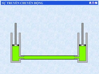
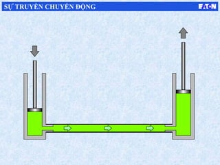
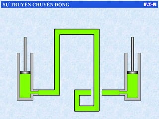
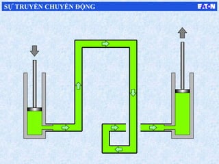
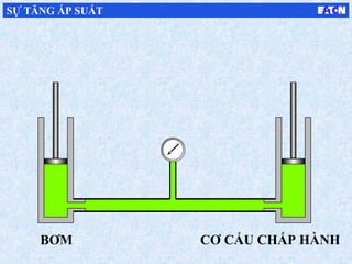
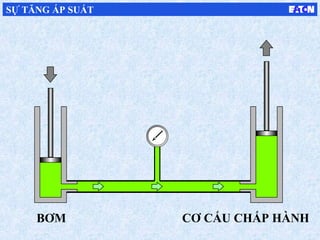
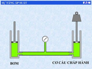
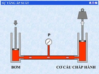
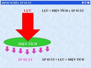
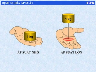
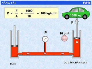

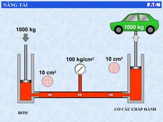
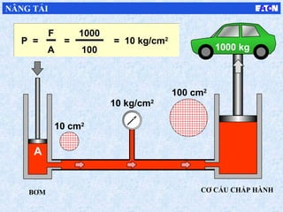
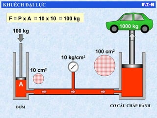
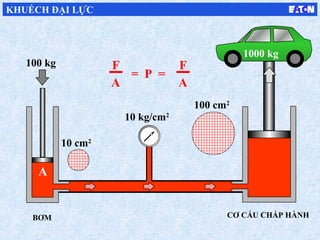
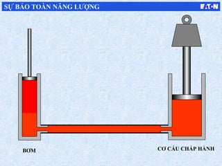
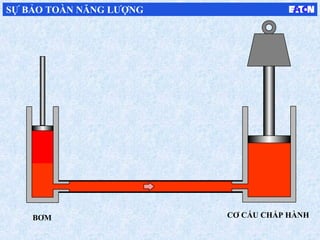
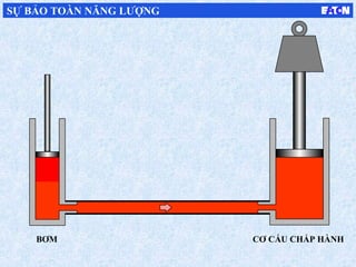
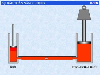
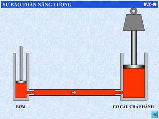
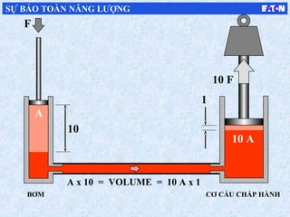

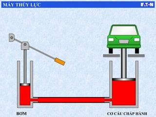
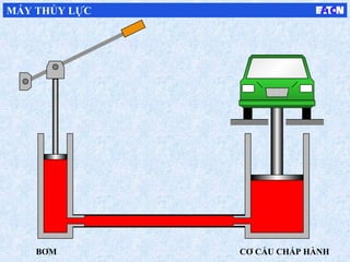
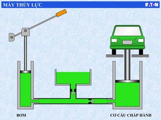
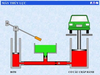
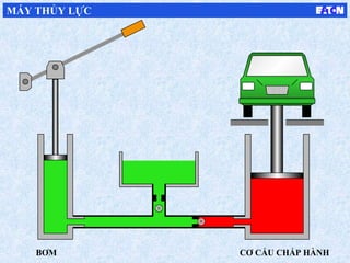
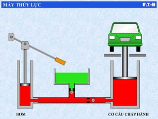
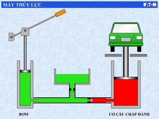

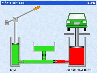
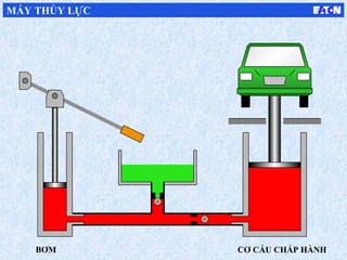
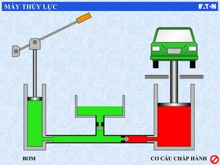
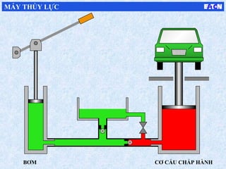
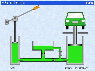
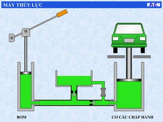
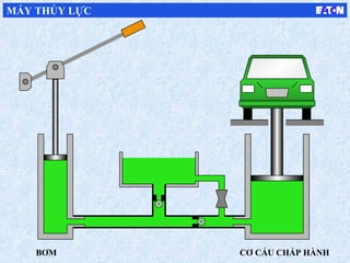
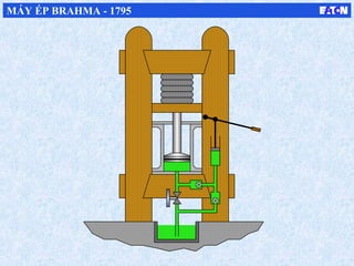
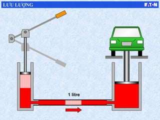
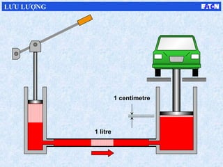
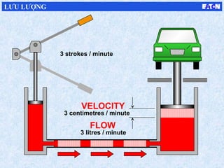
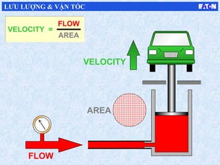
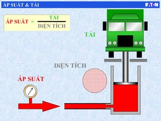
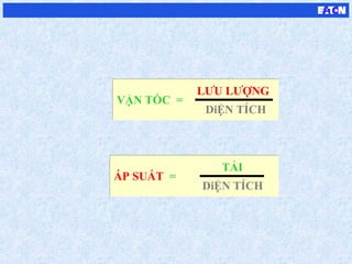
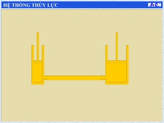

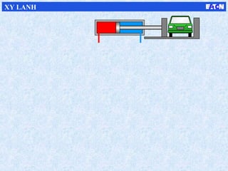
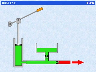
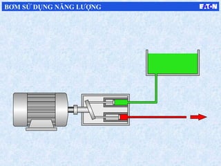
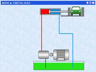
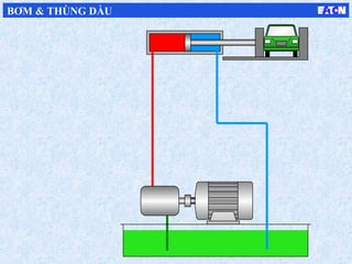
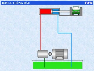

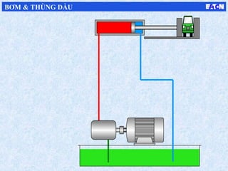

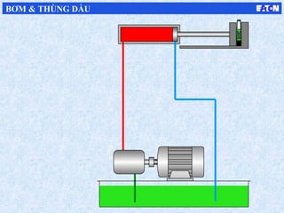

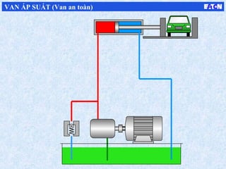

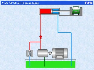
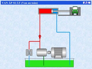
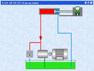
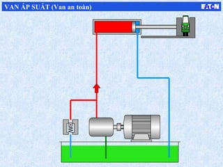
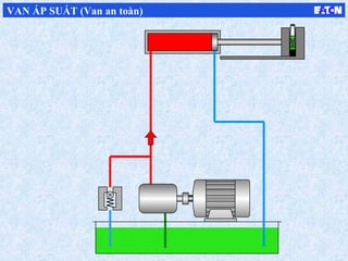
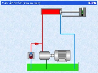
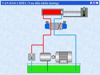
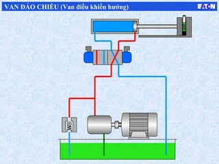
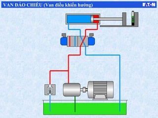
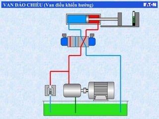
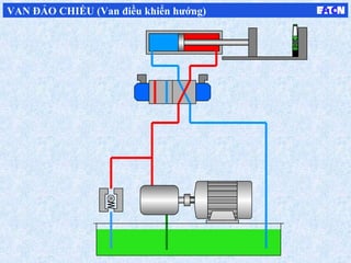
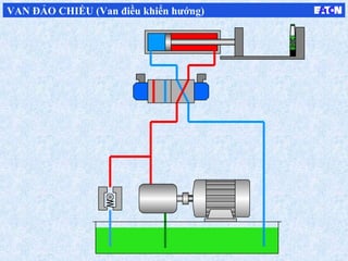
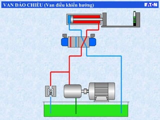

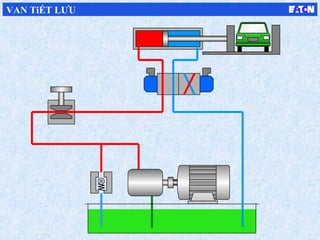

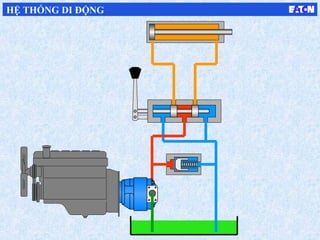
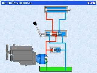
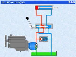
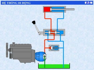
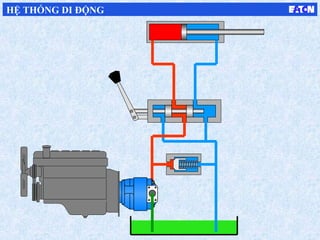
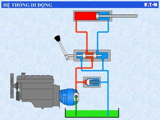
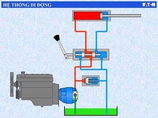
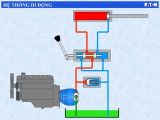

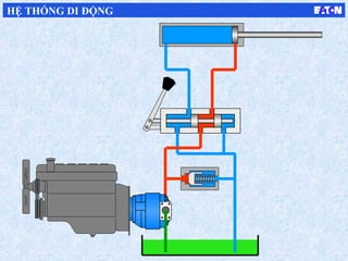
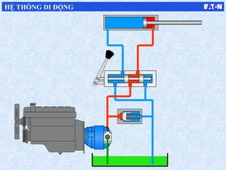

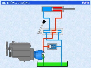
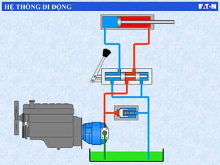

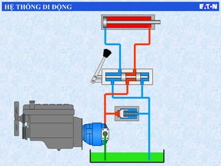
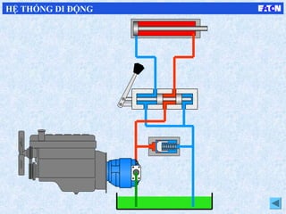
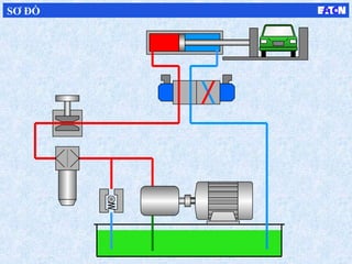
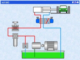
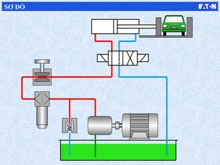
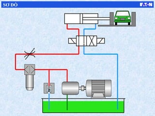

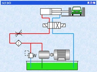
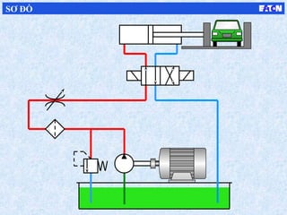
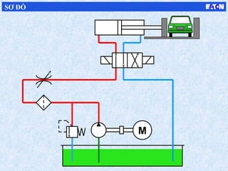
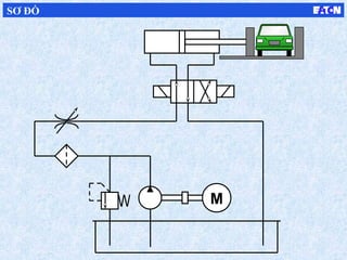
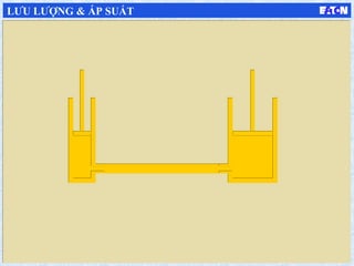
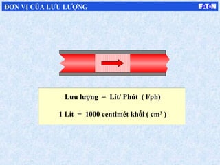
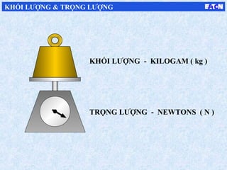
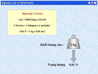
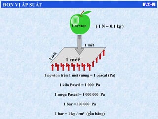
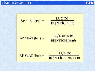
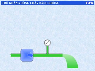
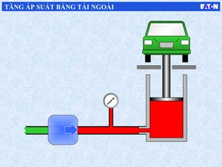
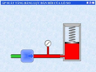
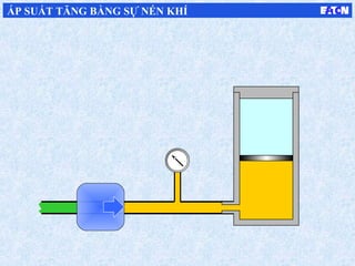
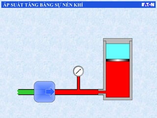
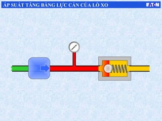
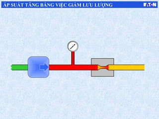
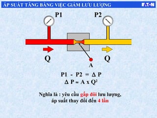
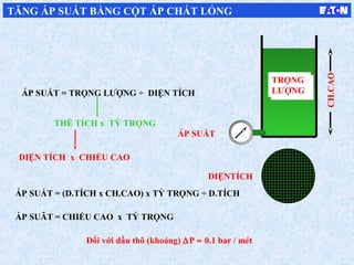
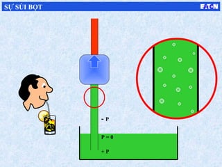
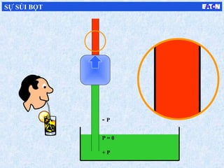
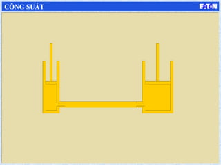
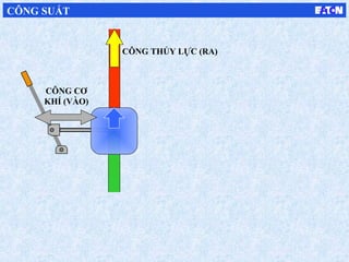
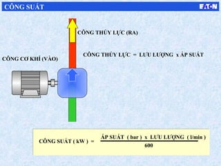
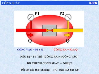

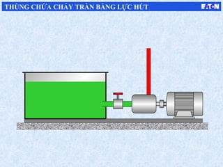
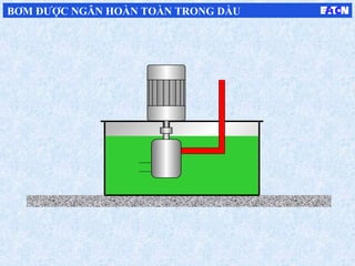
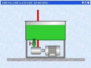
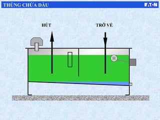
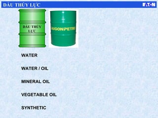
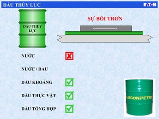
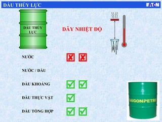
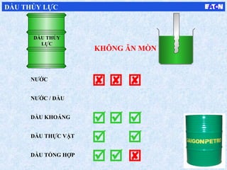
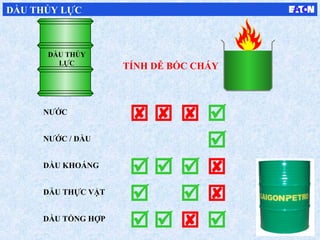
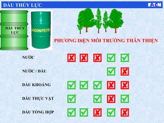
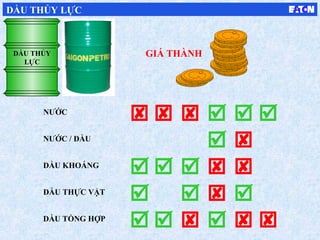
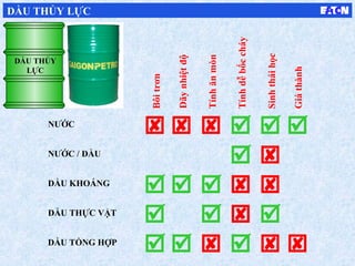
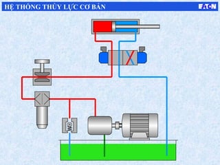
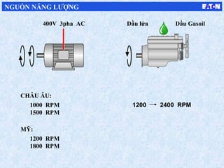
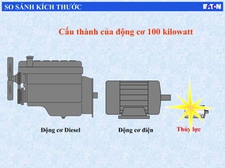
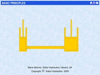


Tài liệu mô tả các nguyên lý cơ bản của hệ thống thủy lực, bao gồm cách thức truyền năng lượng và điều khiển thông qua áp suất của lưu chất. Nó trình bày các khái niệm như áp suất, công suất, và các yếu tố liên quan đến hiệu suất và năng lượng của hệ thống. Hệ thống thủy lực được ứng dụng trong nhiều lĩnh vực thông qua cấu tạo của bơm, van và các cơ cấu chấp hành.


![[BTL] Kiểm tra tính ổn định của hệ thống liên tục](https://cdn.slidesharecdn.com/ss_thumbnails/kimtratnhnnhcahthnglintc-141116074032-conversion-gate02-thumbnail.jpg?width=640&height=640&fit=bounds)


