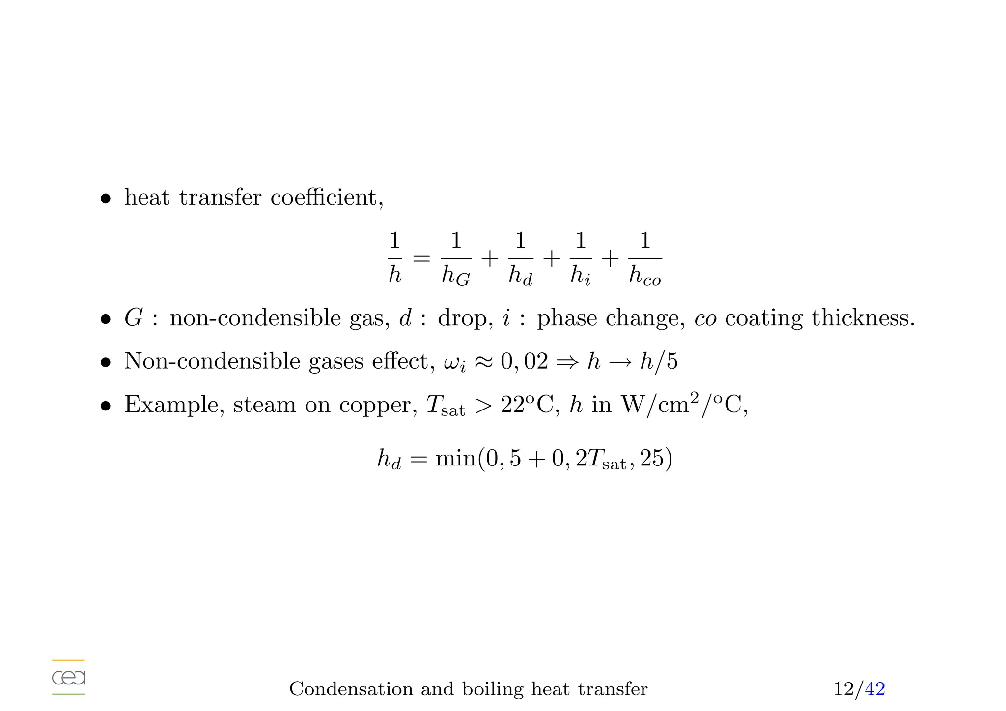
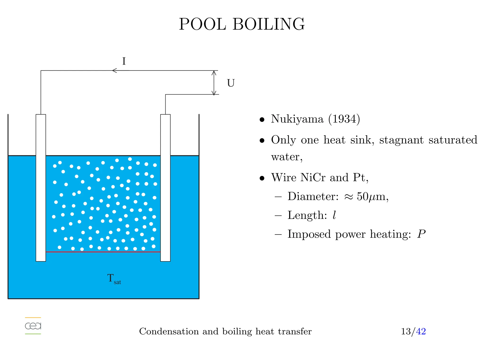
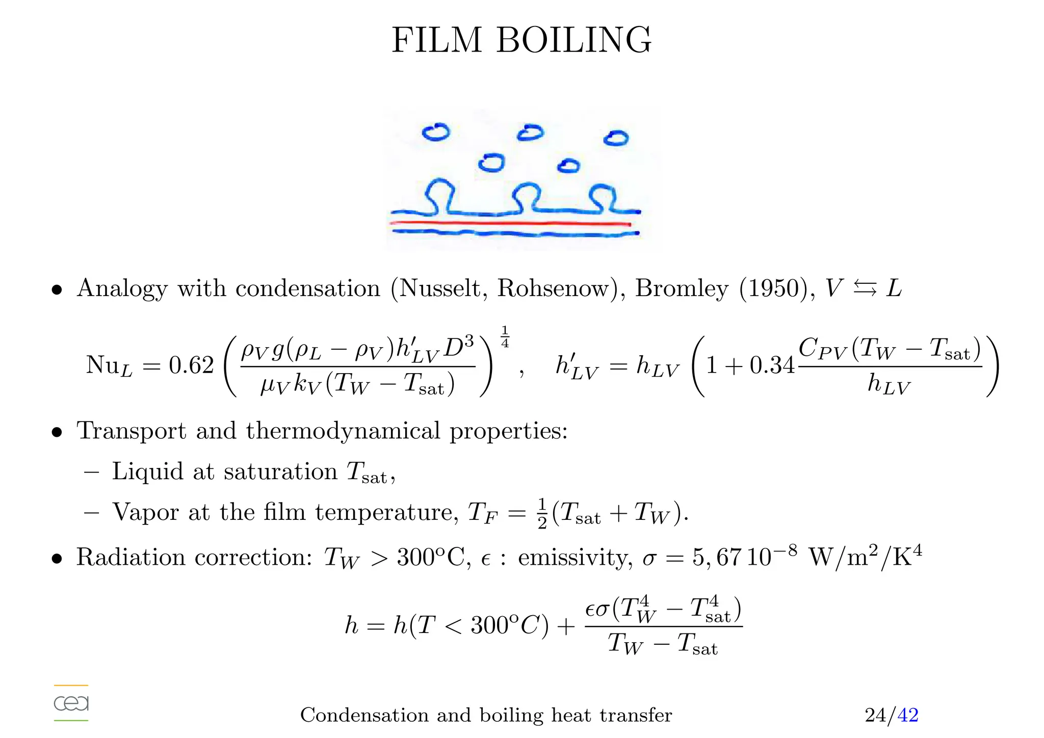
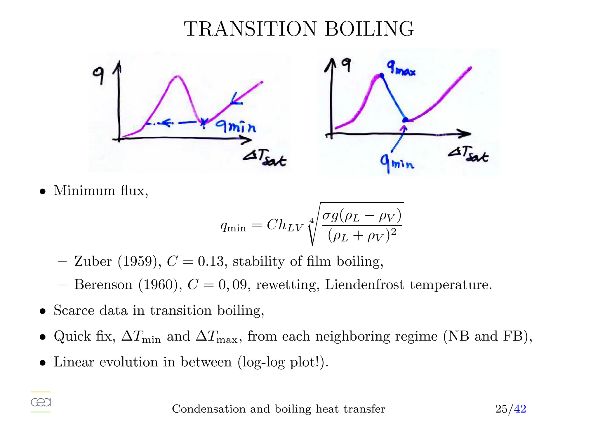
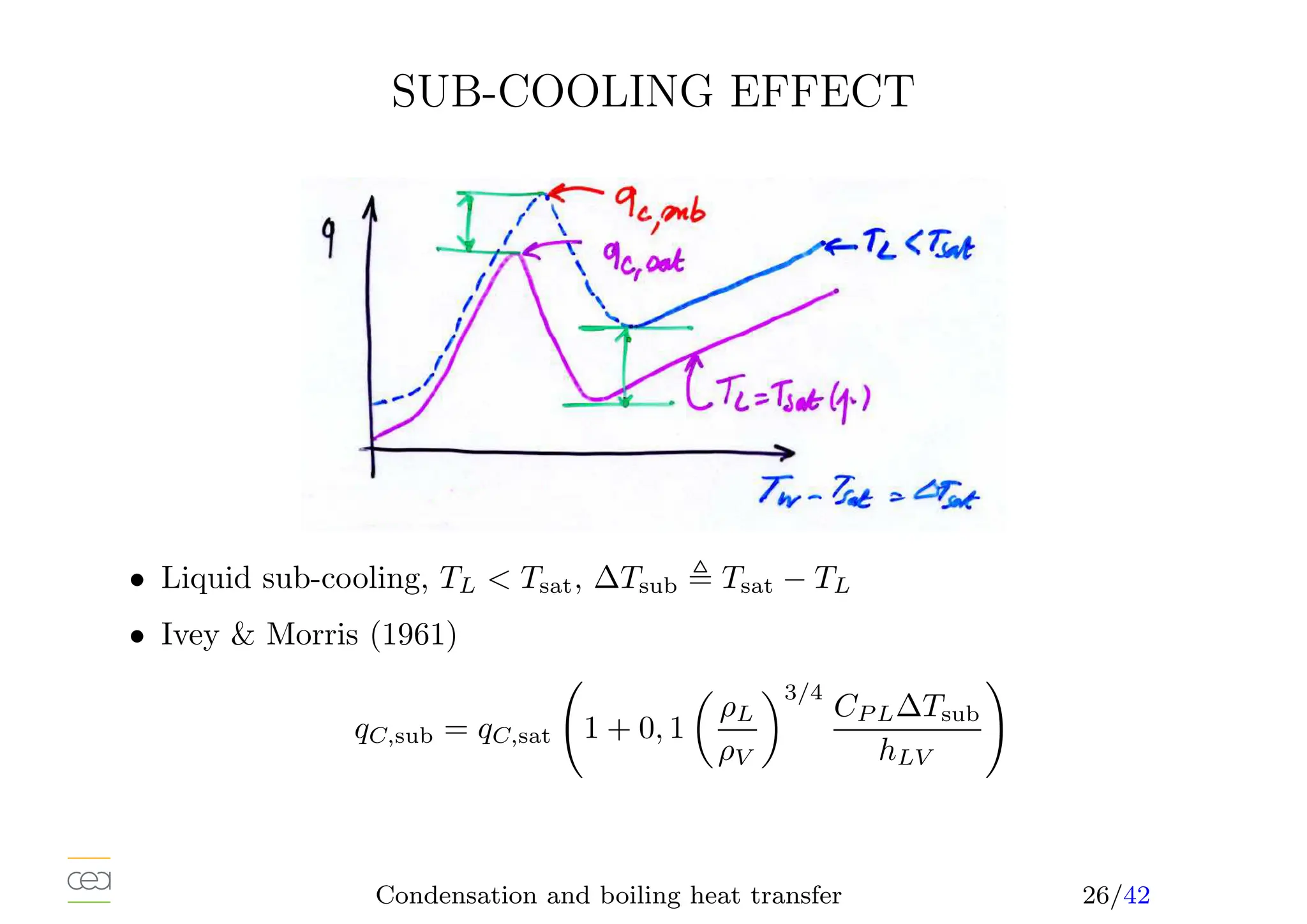
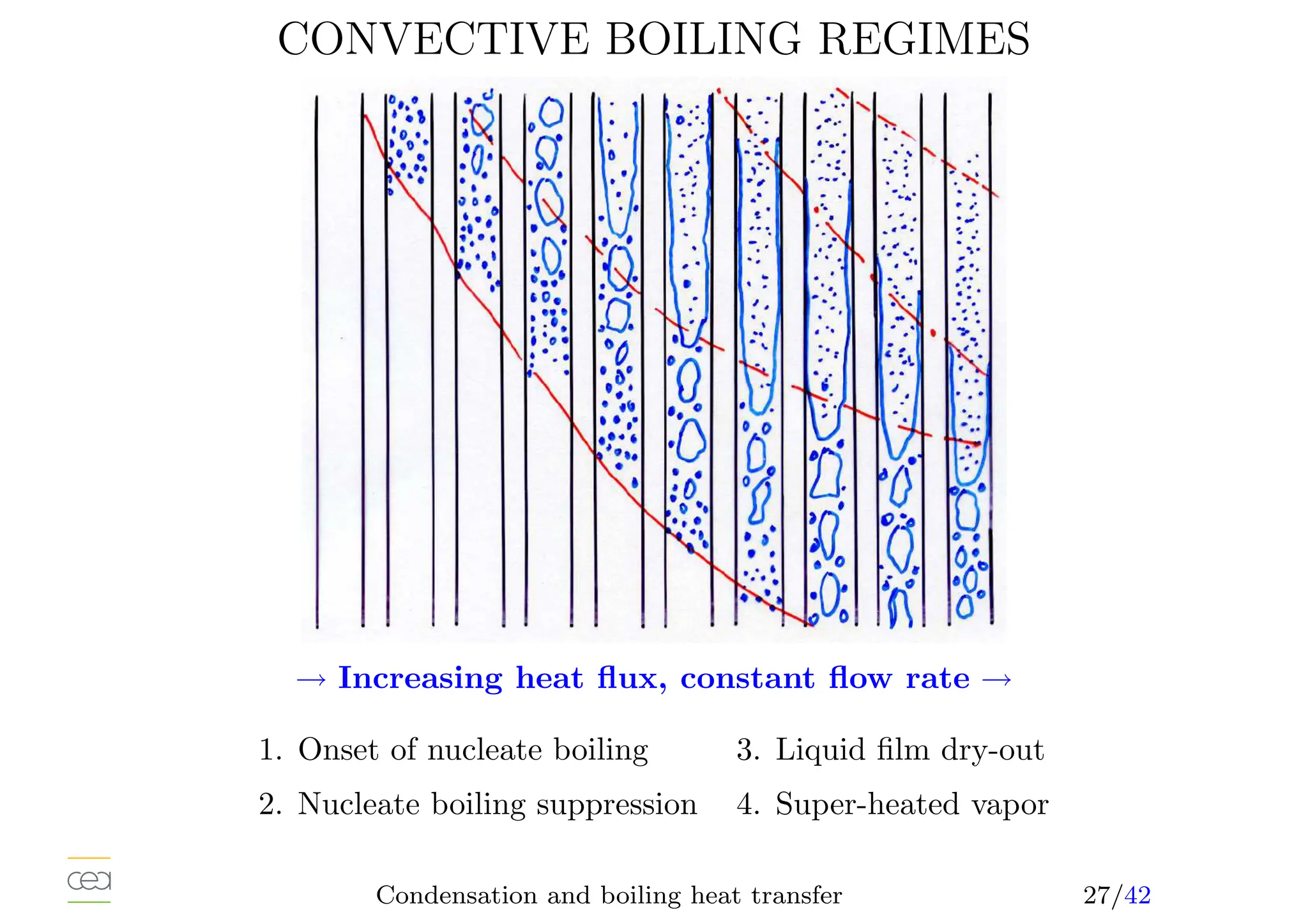
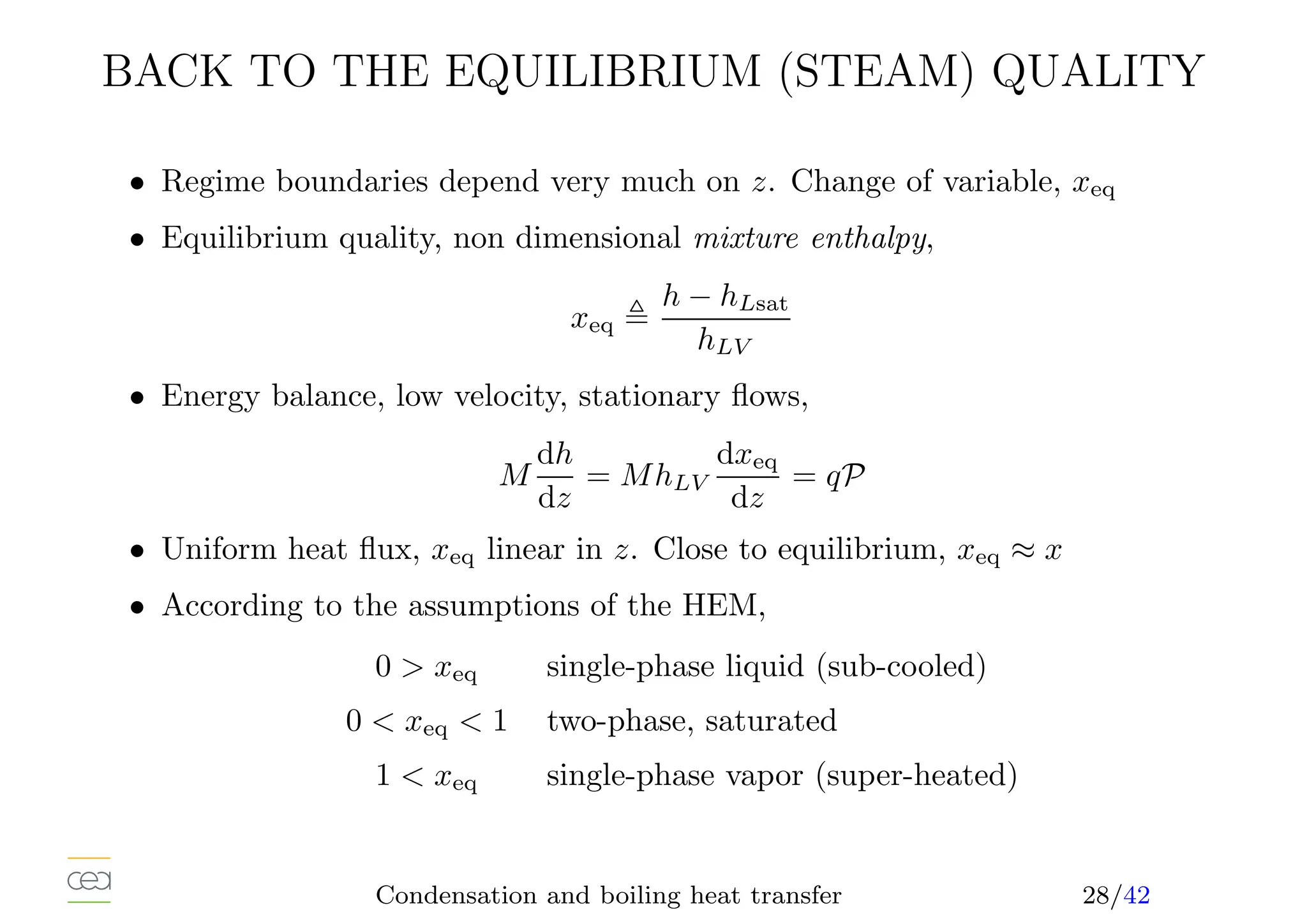
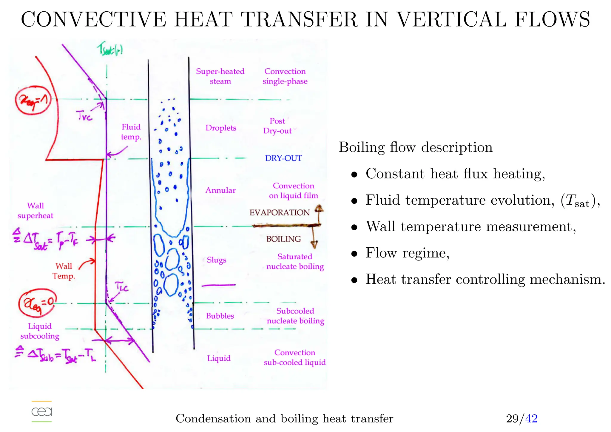
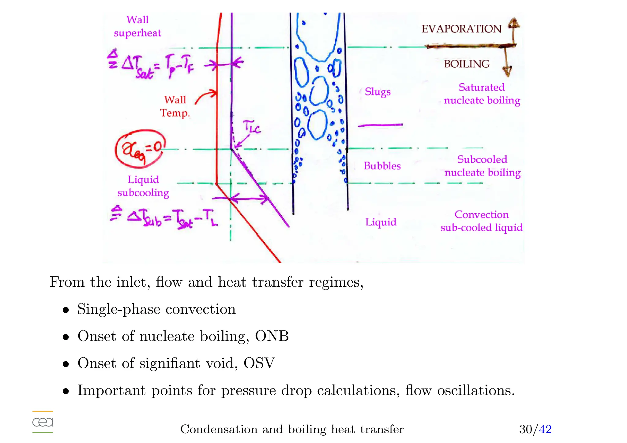
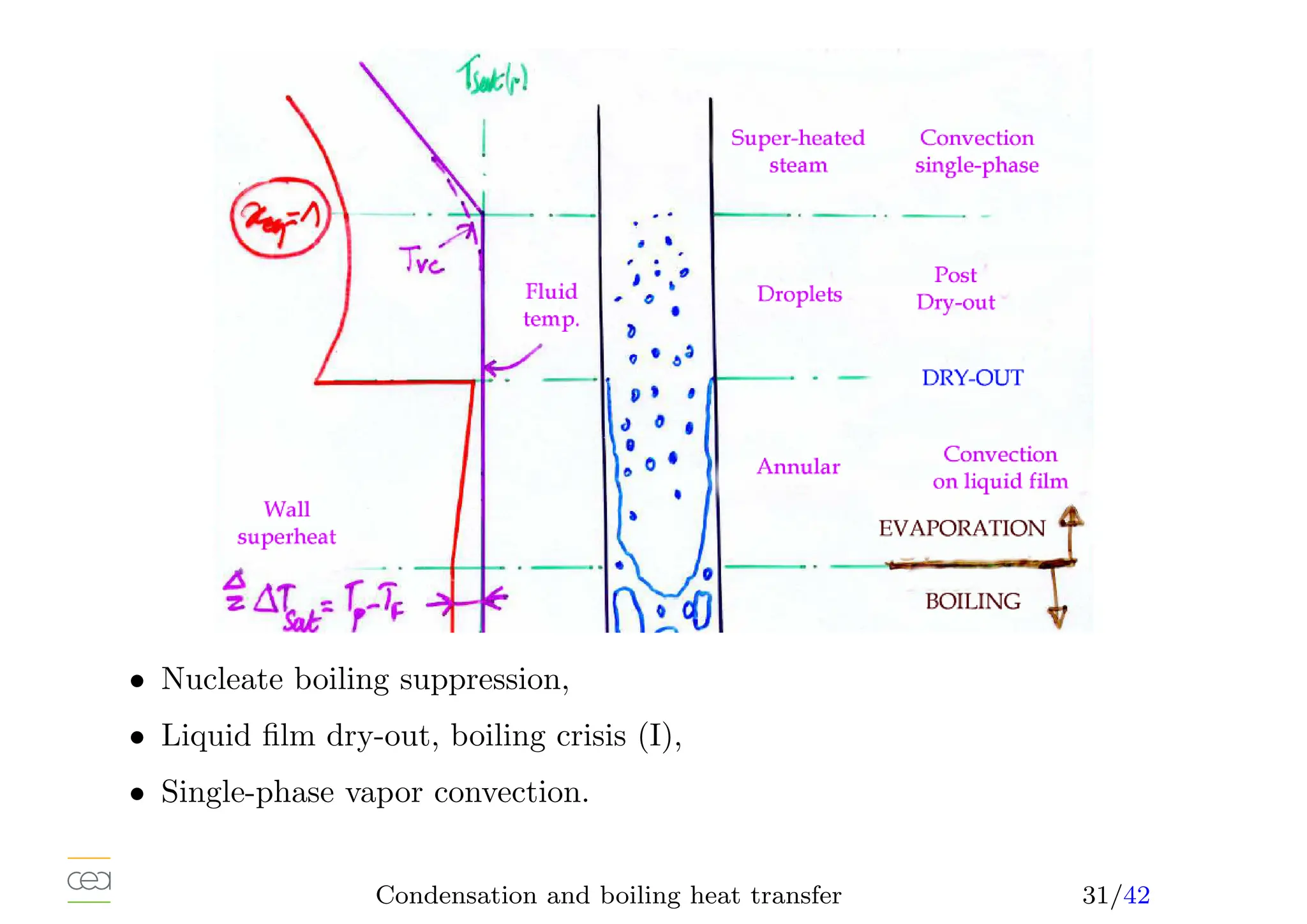
This document provides an overview of two-phase flow heat transfer mechanisms, focusing on condensation and boiling processes. It discusses various heat transfer coefficients and flow regimes for both pure fluids and mixtures, detailing factors like film characteristics, system configurations, and the effects of non-condensable gases. The document emphasizes the significance of understanding these mechanisms for optimizing thermal management in engineering applications.
![HEAT TRANSFER MECHANISMS
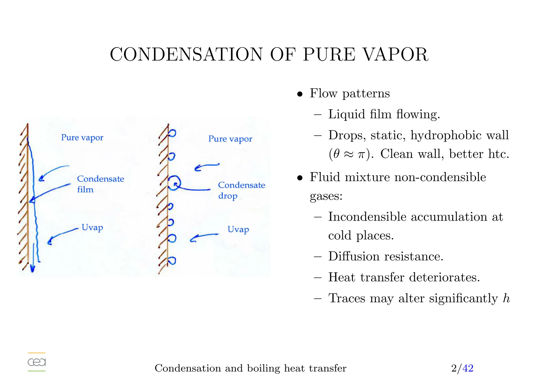
• Condensation heat transfer:
– drop condensation
– film condensation
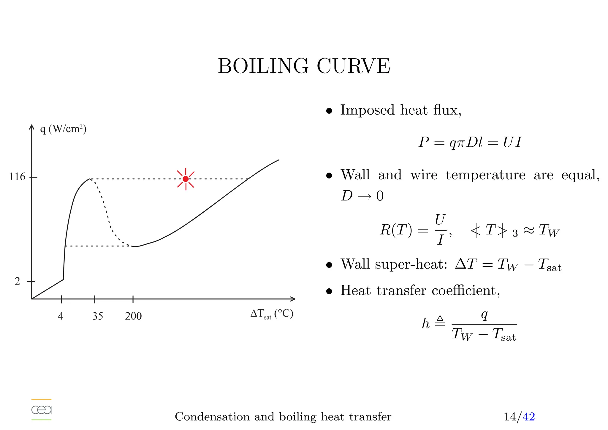
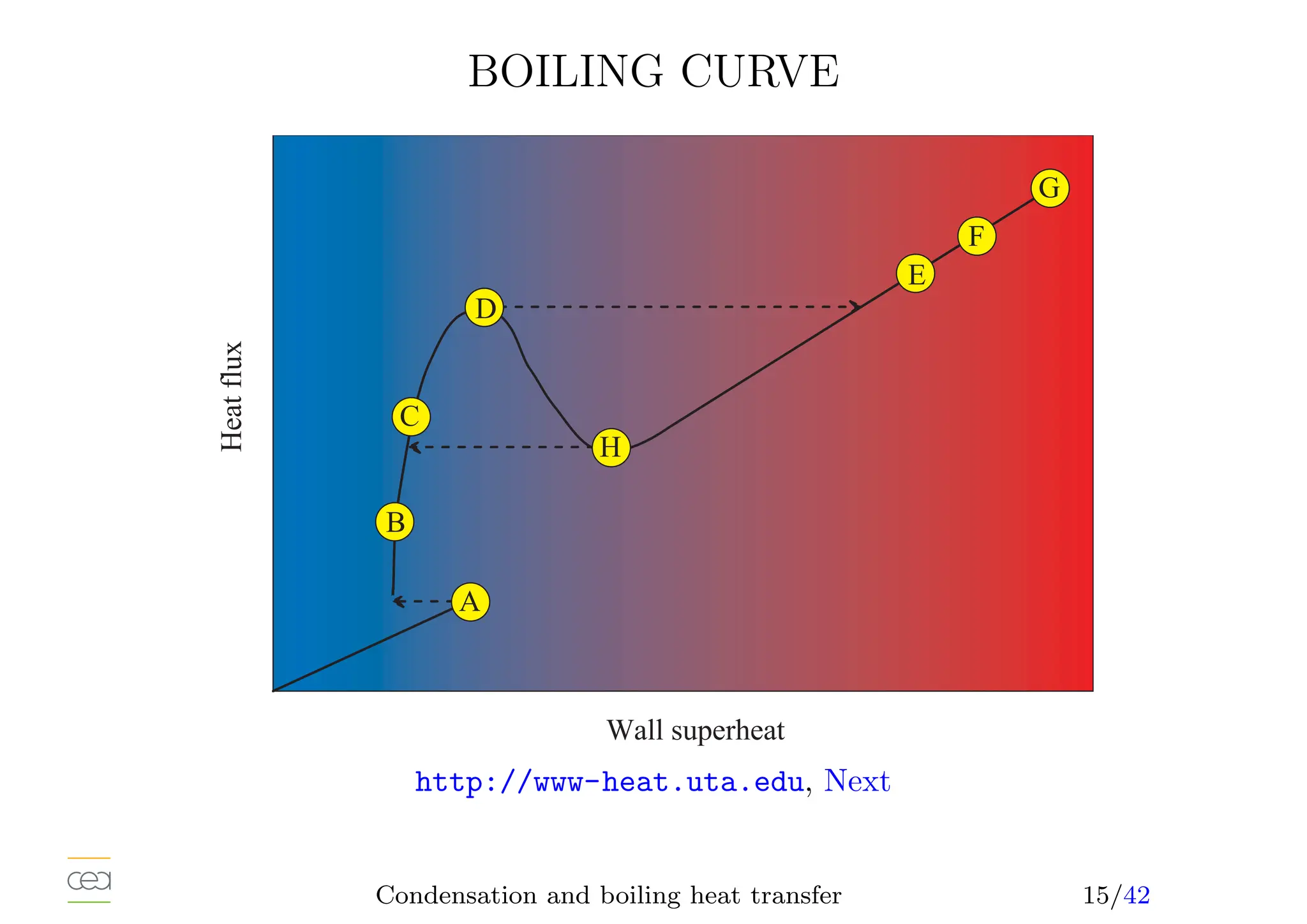
• Boiling heat transfer:
– Pool boiling, natural convection, ébullition en vase
– Convective boiling, forced convection,
• Only for pure fluids. For mixtures see specific studies. Usually in a
mixture, h ⩽
P
xihi and possibly hi.
• Many definitions of heat transfer coefficient,
h[W/m2
/K] =
q
∆T
, Nu =
hL
k
, k(T?)
Condensation and boiling heat transfer 1/42](https://image.slidesharecdn.com/05-slides-240722181501-138b018d/75/Introduction-to-Two-phase-flow-heat-transfer-2-2048.jpg)
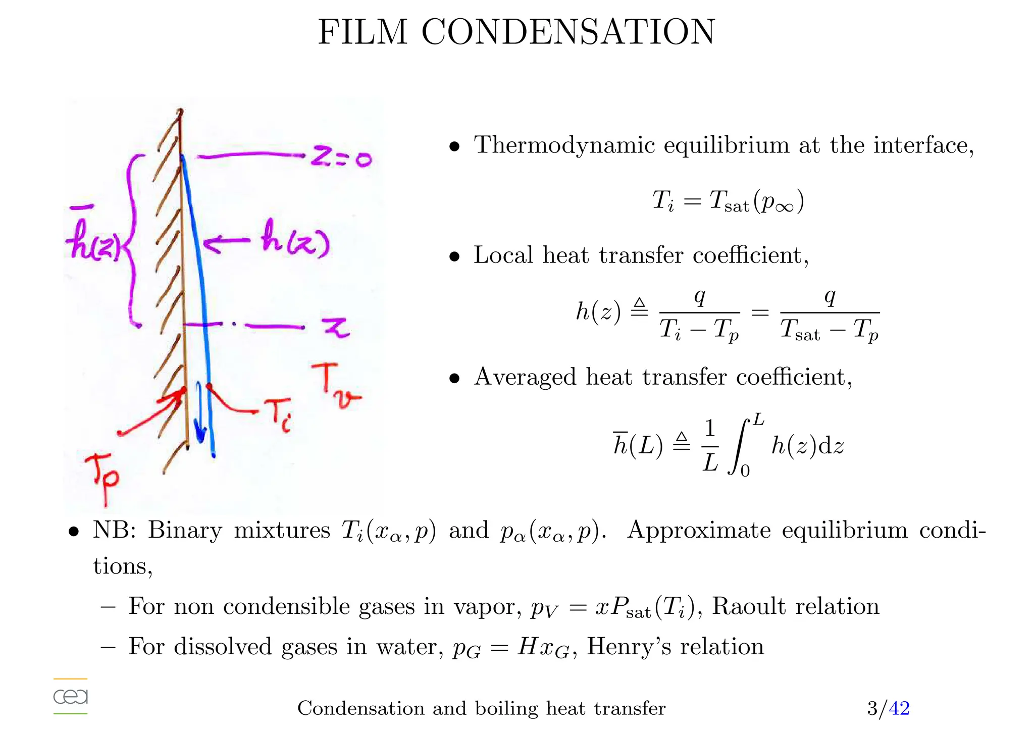
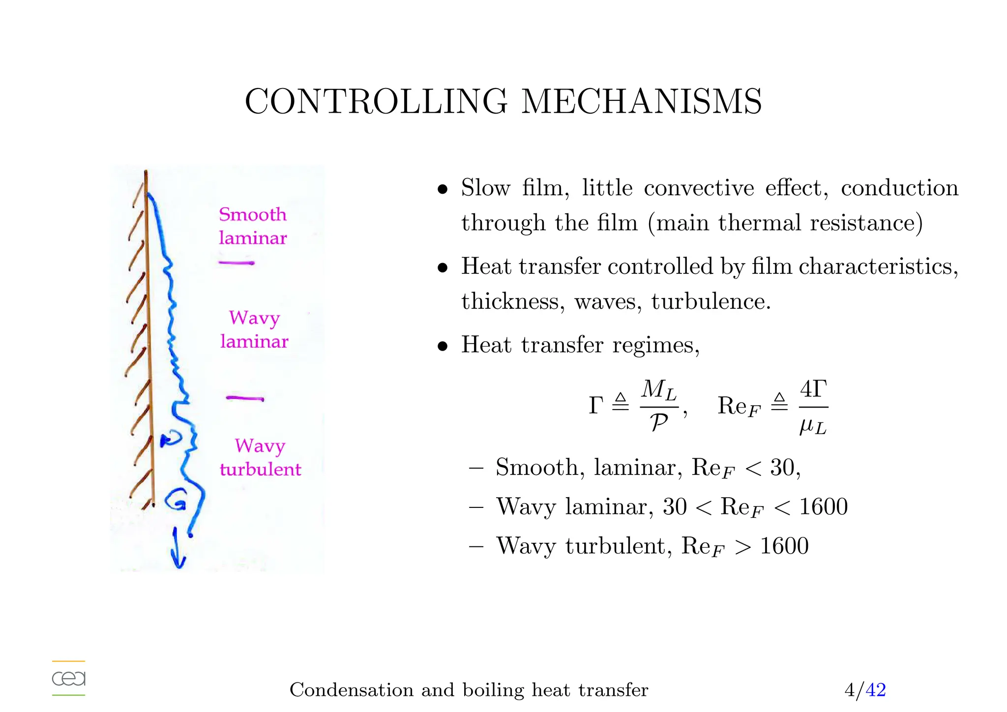
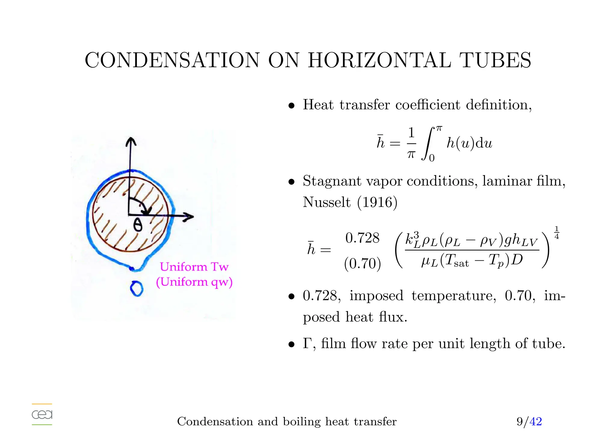
![CONDENSATION OF SATURATED STEAM
• Simplest situation, only a single heat source: interface, stagnant vapor,
• Laminar film (Nusselt, 1916, Rohsenow, 1956), correction 10 to 15%,
h(z) =
k3
LρLg(ρL − ρV )(hLV +0, 68CP L[Tsat − TP ])
4µL(Tsat − TP )z
1
4
• Averaged heat transfer coefficient (TW = cst) : h(z) ∝ z− 1
4 , h(L) = 4
3 h(L)
• Condensate film flow rate, energy balance at the interface,
Γ(L) =
h(L)(Tsat − TP )L
hLV
• Heat transfer coefficient-flow rate relation,
h̄(L)
kL
µ2
L
ρL(ρL − ρV )
1
3
= 1, 47 Re
− 1
3
F
• hLV and ρV at saturation. kL, ρL at the film temperature TF , 1
2 (TW +Ti),
• µ = 1
4 (3µL(TP ) + µL(Ti)), exact when 1/µL linear with T.
Condensation and boiling heat transfer 5/42](https://image.slidesharecdn.com/05-slides-240722181501-138b018d/75/Introduction-to-Two-phase-flow-heat-transfer-6-2048.jpg)
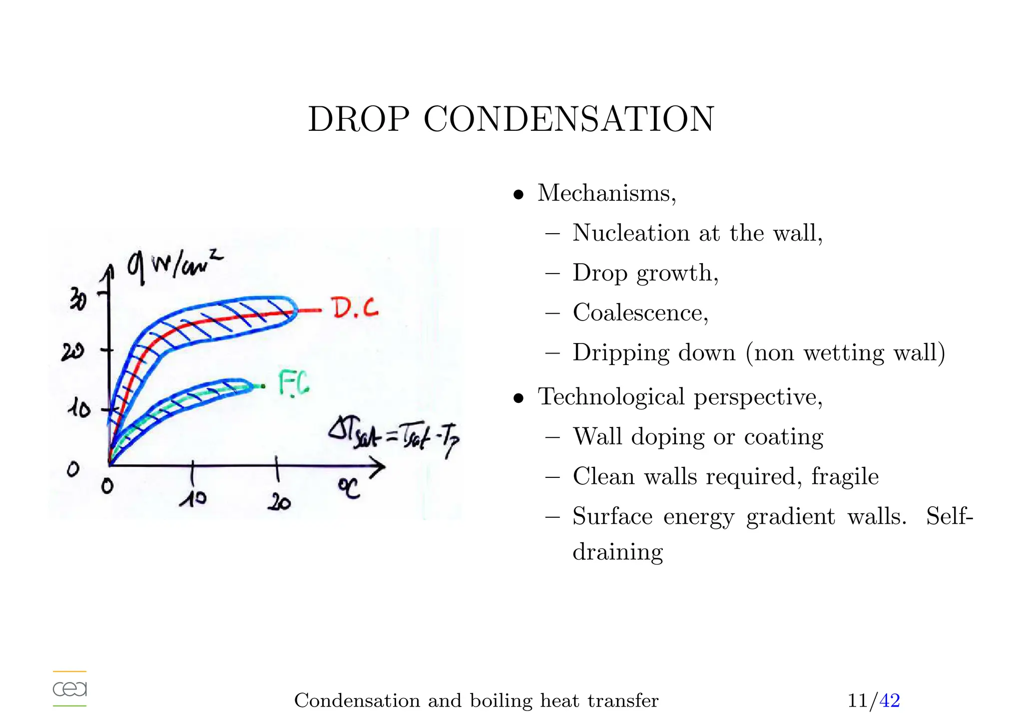
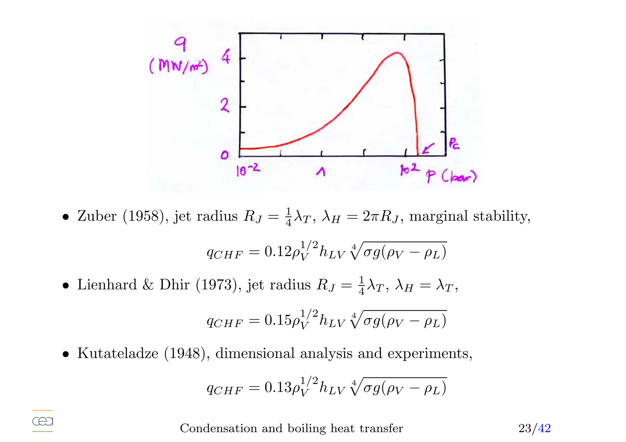
![MAIN PARAMETERS EFFECT ON CHF
After Groeneveld Snoek (1986), tube diameter, D = 8 mm.
0
1000
2000
3000
4000
5000
6000
7000
8000
9000
10000
−20 0 20 40 60 80 100
CHF[kW/m
2
]
exit quality [%]
G=1000 kg/s/m2
P= 10 bar
P= 30 bar
P= 45 bar
P= 70 bar
P= 100 bar
P= 150 bar
P= 200 bar
0
1000
2000
3000
4000
5000
6000
−20 0 20 40 60 80 100
CHF[kW/m
2
]
exit quality [%]
p=150 bar
G= 0 kg/s/m2
G=1000 kg/s/m2
G=5000 kg/s/m2
G=7500 kg/s/m2
• Generally decreases with the increase of the exit quality. qCHF → 0, xeq → 1.
• Generally increases with the increase of the mass flux,
• CHF is non monotonic with pressure.
Condensation and boiling heat transfer 40/42](https://image.slidesharecdn.com/05-slides-240722181501-138b018d/75/Introduction-to-Two-phase-flow-heat-transfer-41-2048.jpg)