Download to read offline
![SIEMENS Spring Training – Dallas 2006
page 1 of 10
Siemens Energy & Automation, Inc.
SINAMICS LAB HMI (ProTool) Interface
Exercise: Configuration of the drive unit with Servo control
with an HMI (ProTool) Interface
Using the training-case SINAMICS S120
Task 1: Online / Offline configuration of a SIMOTION SCOUT / STARTER – project
and download to the target system
NOTE:
This HMI lab can be started from the SERVO lab #1 as a starting point.
Open your completed Lab #1 and Save As HMI
Offline configuration of SERVO_02
Double Click [ Configuration ]
Click [ Configure DDS ]
This lab requires the use of Extended Setpoint Channel to address the speed
setpoints via the HMI.
CU320
RAM
Scout or
Starter
Load into target system ROMSave to ROM](https://image.slidesharecdn.com/infoplcnetsinamicshmilab1-200719075918/85/Info-plc-net_sinamics-hmi-lab-1-1-320.jpg)
![SIEMENS Spring Training – Dallas 2006
page 2 of 10
Siemens Energy & Automation, Inc.
Configure DDS sequence:
Select [ Continue ] Select [ Continue ]
Accept all the remaining configurations as set up from Lab #1 exercise.
Repeat this same configuration [ Extended setpoint channel ] for SERVO_03
Save and compile](https://image.slidesharecdn.com/infoplcnetsinamicshmilab1-200719075918/85/Info-plc-net_sinamics-hmi-lab-1-2-320.jpg)
![SIEMENS Spring Training – Dallas 2006
page 3 of 10
Siemens Energy & Automation, Inc.
Go back Online
Open the [ Control Logic ] configuration for SERVO_02 and select p840[0] BI: ON/OFF
as R2094: Bit 0, BO: PROFIBUS PZD receive.
This was selected based on the Function Diagram:
Figure 2-54 2460 - Receive telegram, free interconnection via BICO (p0922 = 999)
The next page shows the connection between the parameter written to by the HMI and the
r2094 parameter selected by p840[0] BI: ON/OFF1
Select [ Download ]](https://image.slidesharecdn.com/infoplcnetsinamicshmilab1-200719075918/85/Info-plc-net_sinamics-hmi-lab-1-3-320.jpg)
![SIEMENS Spring Training – Dallas 2006
page 4 of 10
Siemens Energy & Automation, Inc.
This is an excerpt from the Function Diagrams of the S120 Manual:
The above function diagram can be viewed on page 2-777 of the Parameter List & Functions
Sinamics manual: SINAMICS_S_Listenhandbuch_0605_eng.pdf
The HMI application is configured to write
a 1 or 0 to p2098[0].0 which in turn will
gate a 0 or 1 to r2094.0 which will activate
or deactivate the ON/OFF1 bit for the
SERVO](https://image.slidesharecdn.com/infoplcnetsinamicshmilab1-200719075918/85/Info-plc-net_sinamics-hmi-lab-1-4-320.jpg)
![SIEMENS Spring Training – Dallas 2006
page 5 of 10
Siemens Energy & Automation, Inc.
Open the >> Setpoint Channel – Speed Setpoint configuration for SERVO_02
Select p1001[0], CO; Fixed speed setpoint
Open the >> Setpoint Channel – Speed Setpoint configuration for SERVO_03
Select p1001[0], CO; Fixed speed setpoint
NOTE:
The p1001[0] parameter selected for SERVO_02 and p1001[0] are unique for PROFIBUS
mapping. The next section details how the HMI will send data to the p1001[0] (REAL)
registers using the PROTOOL interface.](https://image.slidesharecdn.com/infoplcnetsinamicshmilab1-200719075918/85/Info-plc-net_sinamics-hmi-lab-1-5-320.jpg)

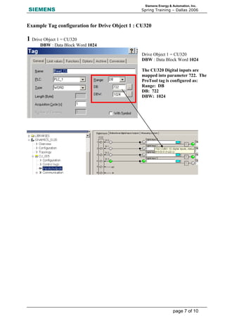
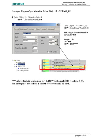
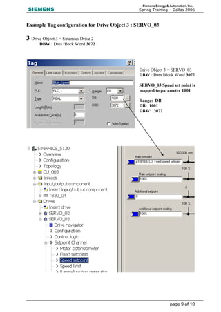
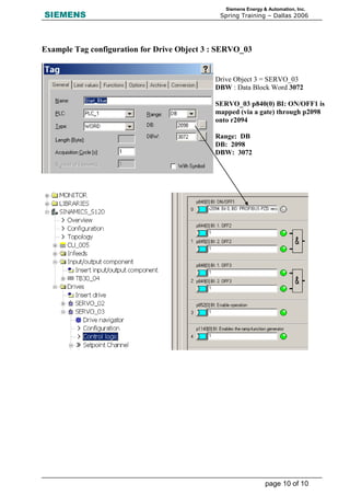

This document provides instructions for configuring a Siemens SINAMICS S120 drive unit with a servo control interface using an HMI (ProTool) interface. The tasks include configuring projects in SIMOTION SCOUT/STARTER and downloading them to the target system. Extended setpoint channels are used to address speed setpoints via the HMI. ProTool tag addressing is done through drive objects to map parameters like control words and speed setpoints for communication.


