Download to read offline

![International Research Journal of Engineering and Technology (IRJET) e-ISSN: 2395-0056
Volume: 09 Issue: 04 | Apr 2022 www.irjet.net p-ISSN: 2395-0072
© 2022, IRJET | Impact Factor value: 7.529 | ISO 9001:2008 Certified Journal | Page 3216
purpose of the components of an aircraft is to generate lift,
most of the components on a racing car are designed to
create downforce, i.e., lift in a negative direction.
Aerodynamics allow tons of downforce to be created on the
front and rear axles, without increasing the weight of the
body; thus, increasingtireadhesion,which,inturn,allowsthe
race car to negotiate a turn at a higher speed.
Downforce aids traction as well; however, the
improvement is not as large when compared to braking or
cornering. The acceleration is limited by the engine power
available. When the car turns and brakes simultaneously, a
significant point to be noted is that even though theresultant
force available to the tires is equal to pure cornering or
braking force, the individual capacities of the components of
the resultant force (cornering andbrakingforce)arelesser.It
can be concluded that braking while negotiating a turn will
reduce the cornering force, leading to an unprecedented
slide. Thus, levels of downforce have to be increased
sufficiently to prevent theslidefromoccurring.Theoretically,
the higher the downforce acting on the car, the faster it can
make the turn without sliding.
Nothing comes free of charge though. The penalty for
excessive downforce comes in the form of increaseddrag[3].
Hence, the main task for aerodynamicists in designing the
bodywork is to optimize the balance betweendownforceand
drag forces created to obtain the fastestpossibletimearound
a race track. Aerodynamics of race cars not only involves the
creation of downforce but also includesareas suchasairflow
to engine box and radiators, cooling of brakes, limiting fuel
sloshing, the release ofexhaustgases,etc.However,thiswork
primarily focuses on the issue of obtaining optimized
downforce and drag values for F1 cars.
In [6] Motorsports are all about maximum performance,
to be the fastest is absolute. There is nothingelse.Tobefaster
you need power, but there is a limit to how much power you
can put on the ground. To increase this limit, force to the
ground must be applied to the wheels. Weight gain can do
this, but weight gain makes it worse and requires more
energy. So we need a realistic weight, we call it downforce
and get in the airflow near the car. The wings have been
shown solely to give a sense of proportion.
Usually, the word "lift" is used to describe any kind of
aerodynamically generated energy that works in space. This
is given an indication, either "positive lift" (top) or "negative
lift" (bottom) in terms of its path. In ground aerodynamics
(cars, bicycles, etc.) the word "lift" is often avoided as its
meaning isalmostalways defined as good, that is, liftingacar
off the lane. The Downforce should always give a sense of
negative force, i.e., to get more traction force.
The desire to continue to increase the adhesion of the
wheels led to a major shift in the construction of race cars,
the use of an improper lift or 'downforce'. As for the tires, the
adhesion of the sides is almost equal to the load on it, or the
friction between the wheel and the road, adding low
aerodynamic strength to the weight component improves
adhesion. The downforce also allows tires to transmit more
power without wheel rotation, which increases the potential
for acceleration. Apart from the aerodynamic downforce to
increase grip, modern racing cars are so powerful that they
can spin wheels or travel at speeds in excess of 160 km/h.
A spoiler is a simple plate placed somewhere on the body
of the car so that it can obstruct or "spoil"theflowaroundthe
vehicle, allowing a controlled separation of the flow at the
desired location. This is done because fast, smooth airflow
leads to positive lift, so impeding this flow either reduces or
perhaps cancels lift altogether.
A rear spoiler is a plate mounted at the rear of the vehicle
and in order for it to be considered a spoiler, the plate must
be integrally attached to the body. If there is space between
the plate and the body, it is considered a wing. The spoiler
causes a split in the back of the car, causingadisturbancejust
before flow, this distortioncausestheflowtoslowdown,thus
reducing the minimum pressure in the area in front of the
spoiler. Therefore, the elevator in the back of the car is
removed. When properly designed, the rear spoiler will
create downforce on the back of the car.
The diffusers, behind the wings, are the tools that are
basically used to create inflation on the back of a race car. In
them, the Bernoulli equation is used as we do with the
venturi tube. It can be seen that in a venturi, the square of
pressure and velocity is inversely proportional. Thus, a
diffuser can help reduce the low pressure under the car to
increase speed.
At the front of a vehicle, the main sources of downforce
are the underbody with the front spoiler (also known as a
spoiler, dam, or splitter), cleats (alsoknownasdivingplates),
vortex generators, and front diffusers.
Spoilers, dams, or splitters are better explained by
following the link. They reduce the gap between the ground
and the vehicle (facing it towards the side of the vehicle) by
blocking as much air as it can get under the vehicle, using a
spoiler on a vehicle with very turbulent airflow on a non-
smooth-floored vehicle can result in less air passing through
all elements of the vehicle's floor, significantly reducing drag
and also reducing lift. (and maybe a little downforce) in this
case.
Duck and the vortex generator in detail. A small fin in the
front corner of a car. Although the inclination of this plate is
minimal, it creates downforce in the front of the vehicle. The
same device can be used in other parts of the car. However,
care must be taken to ensure that the vortex on the leading
edgedoes not interfere with the operation oftherearwingor
other aerodynamic devices. This dive plate is sleeker than
any other and is too small to generate as much downforce.
Instead, it is used to adjust car handling before the race.](https://image.slidesharecdn.com/irjet-v9i4424-220928064252-53520b38/85/Increasing-Downforce-In-High-Speed-Vehicles-Using-Wheel-Rotation-2-320.jpg)
![International Research Journal of Engineering and Technology (IRJET) e-ISSN: 2395-0056
Volume: 09 Issue: 04 | Apr 2022 www.irjet.net p-ISSN: 2395-0072
© 2022, IRJET | Impact Factor value: 7.529 | ISO 9001:2008 Certified Journal | Page 3217
In [1] we can see To achieve the optimized drag for the
vehicle, the research is being carried out on certain add-on
aerodynamicdevicestoreducetheresistanceofferedbywind
and improve the efficiency of the vehicle. In thisresearch,the
effects of various aerodynamic devices like the rear wing,
spoiler, diffuser, and fins are examined and the change in the
coefficient of drag is investigated.
Spoilers are one of the most widely used and important
aerodynamic devices in the automotive industry. Its main
purpose is to help reduce drag by "disturbing" unwanted
airflow and sequencing the airflow. However, the actual use
of the spoiler is noticeable at high speeds above about 120
km/h. Commercial vehicles typically use it to enhance the
appeal of vehicle designs that offer little or no aerodynamic
advantage. So basically, high-performance cars apply it to
achieve higher speeds. The low-pressure area behind the
vehicle is reduced, which creates less turbulence and
consequently reduces drag.
The ultimate aim of every race car designer is to improve
the lap time, without compromisingsafety andotheraspects.
To achieve this objective, the most predominant factor is
cornering ability at high speed. During cornering, the cars
have to reduce their longitudinalacceleration tocompensate
for the lateral acceleration i.e., it has to slow down while
cornering to avoid sliding or deviating from the desiredpath,
as the traction provided by the tire is limited for a given load.
One such way to improve the cornering ability, ultimately
improving lap time, is by improving the traction of the tires
by increasing the load acting on them. Resistance forces
acting on the body are generally of two types: viscous and
forced. Induced drag results from the creation of lift and
viscous drag results from the boundary layer interaction
between the body and the fluid (air in this case). Thus, the
overall drag coefficient for the final wing is calculated.
The best way to increase the load on the tires when
cornering is to increase the car's aerodynamic downforce
coefficient to some extent (up to the critical downforce
coefficient). An important factor in reducing the amount of
resistance is the positive effect of the time delay due to the
decrease in muscle strength on the hip. [2] introduces a
method to determine the most important decelerationfactor
of a vehicle on a specific track. Significant reduction factors
are determined by a series of analytical statistics and
simulations performed using OptimumLap software. The
critical coefficient of downforce for the FSAE- no aero car on
the Buddh International circuit is found to be 2.2 and the
corresponding lap time is 128.950 which isabout10seconds
clear from the lap time by the initial setup without any
aerodynamic downforce.Goingfurtherthecriticalcoefficient,
the lap time increases which is undesirable. So the
aerodynamic add-ons should be designed to reach the
downforce coefficient of 2.2.
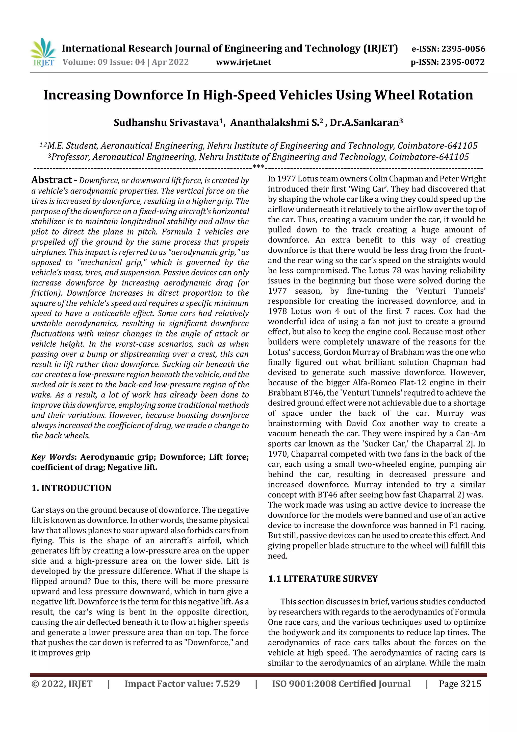
2. METHODOLOGY
The challenge is to decrease the lift that is created due to air
moving under the car and creating an undesirable lift force.
So, to eliminate this effect wheels have been used to ignore
unnecessary power consumption. The rotation of the wheel
itself creates a suction effect that makes the air under the car
model to move out and create a low-pressure area which in
turnincreases downforce withoutaffectingthefuelefficiency
of the car as we used a passive device for the job. The air
exhausted from the wheel will increase drag substantially
due to its rotation. So, to ignore this increase indragfurthera
covering is given for the rear wheel and two holes have been
made to guide the flow to thelow-pressure wake zone which
is made behind the car. So that it can increase the pressureat
the rear end of the which further decrease the drag
coefficient.
2.1 MODEL
For designing the base model car,CATIAV5wasusedand
the basic model was created. Then the file was exported for
analysis in .igs format for Ansys.
Fig -1: Base model car
The three-dimensional car model was imported to the
ANSYS™ workbench. Computational Fluid Dynamics (CFD)
was carried out in the FLUENT module. In Design Modeler,
an enclosure is developed of dimensions 1500 × 300 × 600
mm to form a virtual wind tunnel.
Fig -2: Enclosure](https://image.slidesharecdn.com/irjet-v9i4424-220928064252-53520b38/85/Increasing-Downforce-In-High-Speed-Vehicles-Using-Wheel-Rotation-3-320.jpg)
![International Research Journal of Engineering and Technology (IRJET) e-ISSN: 2395-0056
Volume: 09 Issue: 04 | Apr 2022 www.irjet.net p-ISSN: 2395-0072
© 2022, IRJET | Impact Factor value: 7.529 | ISO 9001:2008 Certified Journal | Page 3219
REFERENCES
[1] Devang S. Nath* , Prashant Chandra Pujari,AmitJainand
Vikas Rastogi, Drag reduction by application of
aerodynamic devices in a race car
https://doi.org/10.1186/s42774-020-00054-7.
[2] Brighton George, Jairesh J. V., Chithraiselvan G., Gokul
Nath S, Determination of Critical Downforce Coefficient
of a Vehicle for Optimum Aerodynamic Performance,
e-ISSN: 2395-0056.
[3] Joseph Katz, “Aerodynamics of Race Cars”.
[4] David Cox, “Brabham f1 ‘fan-car’ bt46b”.
[5] Sir Frank Williams, “Downforce”.](https://image.slidesharecdn.com/irjet-v9i4424-220928064252-53520b38/85/Increasing-Downforce-In-High-Speed-Vehicles-Using-Wheel-Rotation-5-320.jpg)

The document discusses increasing downforce in high-speed vehicles through wheel rotation. Downforce increases tire grip and allows vehicles to corner faster by creating a downward aerodynamic force. Traditionally, downforce was increased through spoilers and wings, but this also increased drag. The authors propose adding propeller-like structures to the wheels to actively increase downforce without increasing drag, by sucking air beneath the vehicle. This method was inspired by fan cars from the 1970s but would use passive devices on the wheels instead of active fans.


