Investigation of PolyMethyl Methacrylate for Speedometer Application
IMAPS 2003 Manuscript - E
1. Unique Metal-to-Glass Bonding
for Hermetic Packaging of MOEMS and Other Applications
David Stark
Electronics Packaging Solutions, Inc.
31252 Island Drive
Evergreen, CO 80439
Phone and Fax: (303) 674-1197
E-mail: David@EPS-Inc.org
Abstract
Hermetic packaging of micro-optoelectromechanical systems (MOEMS) is a maturing technology with
industry-consensus methods and standards still evolving. Off-the-shelf window assemblies are not yet
available. They are generally custom designed and manufactured for each new product, resulting in long cycle
times, high costs and questionable reliability.
There are currently two dominant window-manufacturing methods wherein a metal frame is attached
to glass, and a third, less-used method. The first method creates a glass-to-metal seal by heating the glass above
its Tg to fuse it to the frame. The second method involves metallizing the glass where it is to be attached to the
frame, and then soldering the glass to the frame. The third method employs solder-glass to bond the glass to the
frame.
The feasibility of a novel alternative with superior features compared to the three previously described
window-manufacturing methods has been demonstrated. The new approach lends itself to a plurality of glass-
to-metal attachment techniques. Benefits include lower temperature processing than two of the current methods
and potentially more cost-effective manufacturing than all three of today’s attachment methods. 1
Key words: MOEMS packaging, glass-to-metal seal, kovar, hermetic, diffusion bonding, window, lid
Introduction
Photonic, optical and micro-
optoelectromechanical systems (MOEMS) are
typically packaged such that the active elements (i.e.,
the emitters, receivers, micro-mirrors, etc.) are
enclosed within a sealed chamber to protect them
from handling and other environmental hazards. In
many cases, it is preferred that the chamber be
hermetically sealed to prevent the egress or exchange
of gasses and moisture between the chamber and the
environment. Of course, a window must allow light
or other electromagnetic energy of the desired
wavelength to enter and/or leave the package.
In some cases, the window will be
transparent, e.g. if visible light is involved, but in
other cases the window may be visibly opaque while
still being “optically” transparent to electromagnetic
energy of the desired wavelengths. In many cases, the
window is given certain optical properties to enhance
the performance of the device. For example, a glass
window may be ground and polished to achieve
certain flatness specifications in order to avoid
distorting the light passing through it. In other cases,
anti-reflective or anti-refractive coatings may be
applied to the window to improve light transmission.
Sometimes opaque films with etched openings of
specific shapes are applied to one surface of the
window to control the area that light can enter and/or
exit the package.
Hermetically sealed micro-device packages
with windows are produced using cover assemblies
with metal frames and glass windowpanes. To
achieve hermeticity, the glass window is fused or
soldered to its metallic frame, creating a hermetic
window assembly. This metal-framed window
assembly is subsequently attached to the package
containing the electro-optical device. Soldering or
seamwelding the window assembly onto the device
package typically accomplishes the hermetic sealing
of the window assembly to the metal package or
ceramic package with a metal seal ring.
Seamwelding is accomplished either with a laser or
an electrical-resistance welder. 2
2. Key Properties of Glass and Kovar
For window-and-frame lid assemblies to
exhibit long-term reliability the window must have
minimal residual stresses and the glass-to-metal seal
must be capable of maintaining hermeticity for the
life of the end-use product. Practically all MOEMS
lids are manufactured using glass as the window
material and kovar alloy3
(Fe-29Ni-17Co) as the
frame material.
Each glass has several unique properties
based on its chemical composition, thickness and
manufacturing method, which include its CTE, its
viscosity at specific temperatures, the temperature of
its strain point, annealing point and softening point.
The softening point is the temperature at which glass
the glass has a viscosity of 107.6
dPa s (poise) and
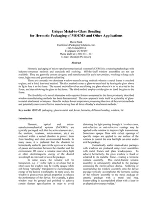
will sag under its own weight. Figure 1 shows that a
basically steady and smooth change in the viscosity
in all temperature regions is a fundamental
characteristic of glass.4
“With few exceptions, the length and the
volume of glasses increase with increasing
temperature. The typical curve begins with a zero
gradient at absolute zero as shown in Figure 1 and
increases slowly. At room temperature (section A),
the curve shows a distinct bend and then gradually
increases up to the beginning of the experimentally
detectable plastic behavior (section B = quasi-linear
region). A distinct bend in the extension curve
characterizes the transition from the elastic to a more
plastic behavior (section C = transformation range).”5
Harner of the Carpenter Technology
Corporation (CarTech) measured the thermal
expansion characteristics of kovar over a temperature
range of –1500
C to 1,1000
C from a starting
temperature of 250
C. 6
His data comprises the first
four columns of Table 1. The first column of the
table lists the temperatures at which measurements
were taken. The second column contains the
measured expansion of kovar from 250
C in parts-per-
million (ppm). The third column is the instantaneous
CTE (ppm/0
C) of kovar at the listed temperature.
The fourth column is the average CTE (ppm/0
C) of
kovar from the listed temperature to 250
C. This was
calculated as the change in expansion (ppm) from
250
C to the listed temperature (column 2), divided by
the change in temperature (∆T = T2 – T1 (250
C),
column 1). The fifth column contains the average
CTE requirements for kovar (ppm/0
C +/- 0.2 ppm/0
C)
from specific temperatures (column 1) to 300
C, per
MIL-I-12011C.7
The CarTech measurements, based
on 250
C ambient, are within 0.1 ppm/0
C of the
margin of error (+/- 0.2 ppm/0
C) of the Mil-Spec
requirements that are based on 300
C ambient.8
Figure 2. Example of a viscosity-
temperature curve for glass
Both the instantaneous CTE data (Alpha
CTE, column 3) and the average CTE data (columns
4-5) indicate the non-linear nature of kovar’s
expansion characteristics. Another interesting and
important feature is that kovar’s minimum
instantaneous CTE and minimum average CTE from
ambient is at approximately 4000
C. CarTech’s data
indicates the room temperature CTE (~ 22-250
C) to
be approximately 6.7 ppm/0
C.
The reliability of glass-to-kovar seals
depends in large part on minimizing the stress of the
bond over the intended temperature-use range. The
expansion data in Table 1 must be employed to
achieve reliable glass-to-metal seals for
manufacturing hermetic window assemblies.
Figure 1. Typical thermal
expansion-temperature curve for
Figure 3 is a graph of the data from MIL-I-
12011C (Table 1, Column 5). This graph shows the
extreme non-linearity of the average CTE of kovar
from elevated temperature back to ambient (300
C).
3. The true reasons that windows crack either during the
last thermal process of the manufacturing operation,
or during environmental temperature cycling are
poorly understood or recognized, especially the data
in Figure 3. Too often, the assembly’s glass window
is in tension during or after manufacturing, and thus
is prone to cracking.
Table 1. Thermal expansion characteristics of Fe-
29Ni-17Co alloy
EXPANSION CHARACTERISTICS OF KOVAR ALLOY
Carpenter Specialty Alloys' Data
MIL-I-
12011C
TEMP EXPANSION ALPHA*
C.O.E.
(CTE)**
C.O.E.
(CTE)***
(
0
C) (ppm) (ppm/
0
C) (ppm/
0
C) (ppm/
0
C)
-150 -1,130 5.9 6.5
-100 -810 6.4 6.5
-50 -485 6.5 6.5
0 -175 6.6 6.9
50 165 6.3 6.5
100 480 5.9 6.4
150 765 5.3 6.1
200 1,025 4.9 5.8 5.5
250 1,260 4.5 5.6
300 1,475 4.3 5.4 5.1
350 1,695 4.4 5.2
400 1,925 5.2 5.1 4.9
435 2,130 9.3 5.2
450 2,300 11.9 5.4 5.3
500 2,975 14.6 6.3 6.2
550 3,740 15.8 7.1
600 4,555 16.7 7.9 7.9
650 5,400 17.3 8.6
700 6,275 17.8 9.3 9.3
750 7,175 18.1 9.9
800 8,090 18.5 10.4 10.4
850 9,060 19.0 11.0
900 10,045 19.3 11.5 11.5
950 11,050 19.5 11.9
1,000 12,030 19.7 12.3
1,050 13,015 19.8 12.7
1,100 14,030 20.0 13.1
* Instantaneous Alpha (Instantaneous Coefficients of
Expansion)
**Average Coefficients of Expansion Determined from 25
0
C
***Average Coefficients of Expansion Determined from 30
0
C
The average CTE from 300
0
C to 100
0
C (same as 100
0
C to
300
0
C) is calculated as:
((1,475 ppm - 480 ppm = 995 ppm) / (300
0
C - 100
0
C =
200
0
C)) = 4.975 ppm/
0
C
Figure 3. The average CTE curve for
kovar in ppm/0
C, from 300
C to elevated
temperatures, per Mil-I-23011C.
Attributes of a More Efficient Window Assembly
Process
The desired outcome is to develop and
demonstrate a process that produces a glass-to-metal
bond that cannot be disassembled, and is inherently
more hermetic or gas-tight than the bonds produced
by any other method. The process would be simple,
have fewer processing steps and have better
reliability. The following are attributes of the
improved assembly process:
• Direct bonding of the kovar frame (or other
frame material) to glass without an intermediate
joining material.
− No solder alloy, solder-glass, etc.
• Ability to use finished glass during the glass-to-
metal sealing process
− No post-assembly grinding and/or polishing
− Any required coatings could be applied
either before or after bonding, including
anti-reflective (A/R), ultra-violet (UV) and
plated metals (typically for apertures, see
Figure 3)
− Ability to bond concave or convex glass to
the metal frame
• Bond strength equal or stronger than the three
alternative methods
• Hermeticity equal to or better than the three
alternative methods
Diffusion bonding was selected because this process
and the joints produced by its use meets all the
intended goals. “The bonding variables (temperature,
load and time) vary according to the kind of materials
to be joined, surface finish, and the expected service
conditions.” 9
Table 210
compares qualities of the bond
produced by three joining methods: diffusion welding
(diffusion bonding), fusion welding and
brazing/soldering. Advantages of diffusion bonding
include: a) no susceptibility to solidification cracking,
b) no porosity (blowholes, shrinkage), c) no warpage,
d) very high vibration survival and e) bond strength
4. equal to that of the parent material. Its three main
drawbacks are the requirement for careful surface
preparation, precise fit-up and the limited availability
and of large diffusion bonding systems.
Table 2. Properties of the joints formed by
diffusion welding, fusion welding and brazing.
Particulars
Diffusion
Welding
Fusion
Welding
Brazing,
Soldering
Warpage None Heavy Light
Product
precision
Fairly
high
Low High
Disassembly
of joint
No No Yes
Vibration
survival
Very
high
Low High
Corrosion
resistance
Fairly
high
Satisfactory Low
Strength
That of
parent
metal or
material
Close to
that of
parent
metal
That of
solder
Bonding
Adhesive,
diffusion
Cohesive
Cohesive,
adhesive
Susceptibility
to
solidification
cracking
None Strong Weak
Porosity None
Shrinkage,
blowholes
Blowholes,
shrinkage,
diffusion
Process Development with Corning 7056 and
Schott AF-45 Glass
Table 3 shows the physical and thermal
characteristics of the two glass materials. Table 4
compares the chemical compositions of these two
materials.
Five diffusion-bonding trials were
performed in a small, heated vacuum chamber
equipped with a top-mounted hydraulic ram for load
application.
The factors to consider and comprehend in
diffusion bonding kovar to glass are the surface
finishes of the kovar and glass, the CTEs of the two
materials at the bonding temperatures and the
softening point (softening temperature) of the glass.
The kovar frames for the bonding trials were
25.4 mm (1”) square, 35.6 mm (1.4”) tall with wall
thickness of 1.02 mm (0.04”), 2.03 mm (0.02”) inside
corner radius and 1.52 mm (0.06”) outside corner
radius. The frame supplier oxidized half the frames
for each trial. (See Figure 6) Maximum surface
roughness prior to oxidation was 0.382 microns (15
micro-inches).
It was desired to use an off-the shelf,
commercially available optical or technical glass with
average CTEs compatible with kovar. Several
candidates meeting these criteria were listed in the
manufacturer’s literature as being produced in sheet
or block form, but investigation found that preferred
glasses were no longer available in the desired forms
for eventual use as MOEMS windows. Corning 7056
alkali borosilicate glass was selected because it is
commonly used for sealing to kovar and as the
window glass for some production MOEMS
applications, it is currently produced two times per
year, and samples are readily available. For the
trials, panes of 3.43 mm (0.135”) thick glass
polished to 2010 inspection criteria were cut into
approximately 40.64 mm (1.6”) square pieces. (See
Figure 4)
Table 3. Physical and thermal properties of
Corning 7056 glass and Schott AF-45 glass.
Characteristic
Corning
7056
Schott
AF-45
Viscosity
Working Point (104 poise) 1058
0
C
Softening Point (107.6
poise)
718
0
C 883
0
C
Annealing Point (1013
poise)
512
0
C 663
0
C
Transformation
Temperature (Tg) 662
0
C
Strain Point (1014 poise) 472
0
C 627
0
C
Thermal
Coefficient of Expansion
(0-300
0
C)
Coefficient of Expansion
(20-300
0
C)
CTE (25
0
C to set point
679
0
C)
Sheet Thickness
3.43 mm
(0.135”)
1.12 mm
(0.044”)
Table 4. The chemical compositions of Corning
7056 glass and Schott AF-45 glass.
Element
Corning
7056
Molecule
Schott
AF-45
Silicon < 35 % SiO2 49.6 %
Potassium < 10 % K2O
Boron < 10 % B2O3 14.2 %
Aluminum < 2 % Al2O3 11.4 %
Sodium < 1 % Na2O3
Lithium < 1 %
Antimony < 1 % Sb2O3
Barium BaO 24.1 %
Arsenic < 1 % As2O3 0.9 %
5. Figure 5 depicts the experimental setup. In
each trial, a non-oxidized kovar frame was placed on
a glass specimen, a spacer was placed on top of the
frame, another second glass was placed on the spacer
and an oxidized frame was placed on the second glass
specimen. The spacers were of a material that would
not adhere to kovar or glass in the diffusion bonding
process. A hydraulic ram applied a controlled load
on the stack of kovar and glass parts. A radiant heat
source surrounding the fixtured parts inside the
vacuum chamber supplied the thermal energy.
Figure 6 shows the three parts of the
diffusion bonding process. During A, the processing
chamber is evacuated to high vacuum and the
temperature is increased until the load temperature is
achieved. In B, the temperature is maintained while a
controlled load is applied to the parts fixtured
between the hydraulic ram and the base. After a
predetermined time, C, the load is released and the
temperature is slowly brought back to ambient
(room) temperature before the chamber is opened to
remove the bonded parts.
Parameters and Results with Corning 7056
Diffusion-Bonding Trials
Bonding trials using Corning 7056 glass
were attempted at load temperatures (Figure 10 (B))
between 4500
C and 6650
C. Load times ranged from
60 to 300 minutes with static pressures between
14.06 kg/cm2
(200 PSIA) and 21.09 kg/cm2
(300
PSIA).
The first trial was attempted at the highest
temperature, with a 60-minute load application of
14.06 kg/cm2
(200 PSIA). Both kovar pieces were
forced (crept) completely through the glass to the
spacer below the glass. This outcome was
unexpected since the load temperature was below the
published softening point (107.6
poise) of 7180
C and a
few degrees below its set point of 6790
C.
The second trial was performed at the lowest
load temperature in an attempt to find a lower
boundary. Neither the oxidized or non-oxidized
kovar parts bonded to their glass. There was a slight
sticking of the un-oxidized frame to its glass but no
mark was evident on the glass after the frame was
removed.
The next three trials (bonding trials 3-5)
were performed at static load temperatures between
500-5750
C. Load times ranged from 60-300 minutes.
Load pressures were applied to achieve a controlled,
limited creep rate, producing a minimum creep of
approximately 0.127 mm (0.005”) and a maximum
creep of 0.889 mm (0.035”). These last three trials
produced weak mechanical bonds between the glass
windows and both the pre-oxidized and non-oxidized
kovar frames.
Kovar frame,
pre-oxidized
Base
Glass
Spacers
Applied
LoadHydraulic Ram
Kovar frame,
not pre-oxidized
Figure 5. Fixturing of the kovar frames and
the glass inside the diffusion-bonding chamber.
Figure 4. Three components prior to
bonding, from left to right: An oxidized kovar
frame, a non-oxidized kovar frame and a
piece of Corning 7056 glass.
Time
Temperature
A B C
Figure 6. Process profile for conventional
diffusion bonding. The load (pressure) is
applied during time zone B.
6. Figure 7 shows a kovar frame positioned on
top of a piece of glass from the third bonding trial.
This trial produced a weak mechanical bond and less
than 0.005” creep of the frame into the glass.
Figure 8 shows the frame and window from Figure 8
separated and placed side-by-side on top on the
optical test pattern. There was almost no optical
distortion in the glass adjacent to the bond area.
Conclusions from the First Bonding Trials
Four of the five bonding trials using Corning
7056 glass resulted in weak mechanical bonds.
These were due to the glass on one side of the kovar
frame being in compression against the frame after
the bonding trial. This is a consequence of the severe
CTE difference of the kovar and the glass from the
elevated bonding temperature back to ambient.
There was no evidence of diffusion bonding of the
glass to the kovar. The following conclusions were
drawn from the initial investigation:
• Four of the five diffusion-bonding trials
produced limited optical distortion of the glass
adjacent to the bond area. This distortion was a
result of the displacement of the glass away from
the frame during creep.
• Limiting the creep reduces the width of the
optically distorted region on each side of the
frame.
• Different temperature, pressure and time
parameters than those used previously might be
required for Corning 7056 glass to achieve not
just mechanical bonding to kovar but also the
desired diffusion bond.
• It might be necessary to use glasses with
different chemical compositions, viscosities and
thermal properties than the Corning 7056.
• Including alternative surface treatments on the
glass and kovar prior to diffusion bonding might
be beneficial.
Second Set of Bonding Trials with Schott AF-45
Glass
A second set of trials was performed using
larger frames than the first set of trials in October,
and Schott AF-45 glass. These trials differed from
the prior trials in two significant ways. The Schott
glass was 1/3 the thickness of the Corning glass and
had a lower CTE, and as such was much more brittle
and after bonding, was under more compression
where it was bonded to the top of the frame and
inside the perimeter of the frame. Conversely, the
Schott glass was under tension exterior to the frame
region. The second, and very significant difference
in the trials was that the second set of trials
succeeded in achieving hermetic, permanent glass-to-
metal seals.
The second used kovar frames from the
same supplier of the first frames. The second set of
frames were larger and the pre-oxidized frames had
intentionally thicker levels of oxidation. The process
for determining the bonding parameters of
temperature and pressure were different. In the first
trials, parameters were chosen based on Corning’s
data for the physical/thermal properties of the glass,
in particular its softening point. The approach was a
trial-and-error. For the second tests, the glass
properties at elevated temperatures were
methodically characterized to determine how the
glass yielded to a 2.54 cm sq. (1 in. sq.) piece of
kovar at various temperatures and pressures. Taking
readings of creep for 10 minutes at specific
temperatures and two levels of applied load, the yield
characteristics of the glass was obtained and graphed.
An initial set of diffusion bonding parameters was
then selected.
The first bonding trial used two non-
oxidized frames on a piece of Schott AF-45 glass,
and two oxidized frames on another piece of the AF-
45 glass. The frames measured 33 mm (1.3”) wide
by 131 mm (3.7”) long with a 2.032 mm (0.08”) wide
bonding surface. The glass pieces were 101.6 mm
(4”) square.
The diffusion bonding temperature zone
used for loading the specimens for the first trial was
approximately 7500
C, which was 1330
C below the
Figure 7. A
kovar frame
embedded less
then 0.127 mm
(0.005”) into the
Corning 7056
glass specimen
from the third
bonding trial.
Figure 8. The third
bonding trial produced a
weak mechanical bond.
The frame is shown
alongside the glass.
Note: The creep of the
frame into the glass is
clearly evident.
7. AF-45’s softening point of 8830
C. The pre-oxidized
kovar frames were successfully bonded to the glass in
this first trial. The results are shown in Figure 10,
which shows two frames bonded to a single piece of
glass. The assembly is held vertically in the left
photo. The assembly is horizontal on grid paper in
the right photo to determine the width the region of
optical distortion adjacent to the kovar frame as a
result of the creep of the frame into the glass and the
corresponding displacement of the glass away from
the frame.
The second bonding trial was performed at
the same bonding parameters of temperature,
pressure and time as the first trial, using a pair of
side-by-side test specimens for each layer of parts in
the experimental setup shown previously in Figure 5.
One pre-oxidized frame was placed on a 50.8 mm
(2”) wide by 101.6 mm (4”) long piece of glass. The
glass was cut using a diamond scribe to scribe-and-
break the parts from a much larger piece. This
process left rough edges containing micro-cracks
along the perimeter of the glass. These micro-cracks
could have been removed by subsequent fire
polishing of the glass, but this was not done. At the
diffusion bonding temperature of about 7500
C,
kovar’s average CTE to ambient during cool-down is
9.75 ppm/0
C while the AF-45’s average CTE is about
4.5 ppm/0
C. Thus the glass exterior to the bonded
portion of the frame was in tension, and as the
assembly reached ambient temperature in the
bonding chamber, the glass exterior to the frame
could be heard cracking. Removing the specimens
from the chamber showed that all this exterior glass
had separated from the frame’s exterior, but the glass
bonded to the frame and the glass inside this region
remained intact.
Due to the difference in the tensile stress
exterior to the frame’s bonding region and the
compressive stress on top of, and inside the bonding
region, some of the remaining glass sheared parallel
to the frame/glass assembly but the remainder had no
cracks or voids and the assembly tested hermetic and
held a vacuum of 10-7
torr. One of these bonded parts
is shown in Figure 10.
Figure 10. AF-45 glass diffusion bonded to a
kovar frame. The glass outside frame
perimeter cracked during bonding cool-down.
Destructive tests performed on the diffusion-
bonded specimens of the first bonding trial
demonstrated that the glass-to-metal seal is
permanent. The specimens were dropped onto
concrete from a height of 5 feet, shattering the glass
inside and outside the perimeter of the metal frame,
but the metal frames still had 100% coverage of
glass. Rough abrasion of the bonded glass could not
remove it from the frames.
Figure 9. Two pre-oxidized kovar frames
bonded to a 101.6 mm (4”) square piece of
Schott AF-45 glass.
More parts were produced for
demonstration, using the same bonding parameters.
To eliminate the shearing of the glass at the corners
of the frames, balanced-construction parts were also
produced. These parts sandwiched 45.7 mm sq. (1.8”
sq.) by 1.12 mm (0.044”) thick Schott AF-45 glass
between a pair of pre-oxidized kovar frames
measuring 33.02 mm (1.30”) by 34.29 mm (1.35”)
with a 2.03 mm (0.080”) wall thickness. These
bonded parts are also held a vacuum level of 10-7
torr,
and are shown in Figure 11.
Figure 11. Pairs of kovar frames sandwiching
a piece of glass after hermetic diffusion
bonding.
8. Conclusions and Summary
The feasibility of Diffusion Bonding Metal
Alloy (Kovar) Directly to Finished Glass to Produce
Hermetic Window Assemblies was proven.
• The bonding was performed below the softening
temperature of the glass windows and does not
affect the optical properties of the windows.
• The thermal properties and chemical
composition of the glass may be critical.
Higher-temperature glass bonding may allow
more atomic mobility, as evidenced by the
successful bonding the Schott AF-45 glass.
• Wider frame widths may be desirable for better
bonding.
Additional tests will prove that diffusion-bonded
glass-to-metal seals are inherently stronger, more
reliable and more hermetic than any other bonding
method. This process holds the potential to be a
lower or lowest cost method to produce hermetic
windows for high-reliability applications because
diffusion bonding uses fewer process steps and
materials than alternative bonding methods.
Acknowledgments
The author would like to thank Olin Aegis of New
Bedford, MA and in particular its Director of Design
Engineering, Luis Couto for providing the kovar
frames used in the diffusion bonding trials; and
Viswam Puligandla, Ph.D. of Flower Mound, TX for
his long-term assistance and recommendations.
References
[1] David Stark, “Novel Hermetic Packaging
Methods for MOEMS”, Proceedings of the 2003
Photonics West Symposium of SPIE: The
International Society for Optical Engineering, San
Jose, CA, January 25-31, pp. 289-300, 2003.
[2] David Stark, “Novel hermetic packaging methods
for MOEMS”, pg. 289.
[3] Kovar® is a registered trademark of the Carpenter
Technology Corporation (CarTech).
[4] Schott Technical Glasses, Schott Glas, Research
and Technology Development Division, Mainz,
Germany, pg. 11.
(http://www.schott.com/epackaging/english/downloa
d/technical_glasses_300dpi.pdf?X=1)
[5] Schott Technical Glasses, pg. 14.
[6] L. L. Harner, “The Use of Fe-29Ni-17Co Alloy in
the Electronics Industry”, Carpenter Technology
Corporation, Reading, PA, pg. 2, 1994.
[7] “Mil-I-23011C, 29 March 1974, Military
Specification: Iron-Nickel Alloys for Sealing Glasses
and Ceramics”, U. .S Government Printing Office,
pp. 1, 4, 6 and 21, 1974.
[8] David Stark, “Novel hermetic packaging methods
for MOEMS”, pg. 293.
[9] N. F. Kazakov, Diffusion Bonding of Materials,
edited by N. F. Kazakov and translated from Russian
by Boris V. Kuznetsov, Pergamom Press Inc.,
Elmsford, NY, pg. 12, 1985.
[10] N. F. Kazakov, Diffusion Bonding of Materials,
pg. 13.