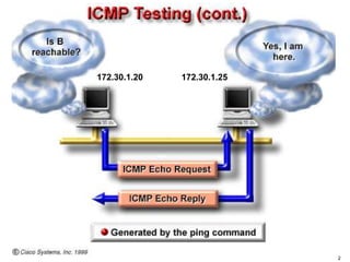
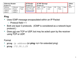
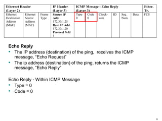
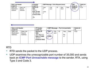
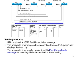
ICMP: Ping and Trace
2
172.30.1.20 172.30.1.25
3
Ping
• Uses ICMP message encapsulated within an IP Packet
– Protocol field = 1
• Both are layer 3 protocols. (ICMP is considered as a network layer
protocol.)
• Does not use TCP or UDP, but may be acted upon by the receiver
using TCP or UDP.
Format
• ping ip address (or ping <cr> for extended ping)
• ping 172.30.1.25
Ethernet Header
(Layer 2)
IP Header
(Layer 3)
ICMP Message
(Layer 3)
Ether.
Tr.
Ethernet
Destination
Address
(MAC)
Ethernet
Source
Address
(MAC)
Frame
Type
Source IP Add.
Dest. IP Add.
Protocol field
Type
0 or 8
Code
0
Check-
sum
ID Seq.
Num.
Data FCS
4
Echo Request
• The sender of the ping, transmits an ICMP message, “Echo Request”
Echo Request - Within ICMP Message
• Type = 8
• Code = 0
Ethernet Header
(Layer 2)
IP Header
(Layer 3)
ICMP Message - Echo Request
(Layer 3)
Ether.
Tr.
Ethernet
Destination
Address
(MAC)
Ethernet
Source
Address
(MAC)
Frame
Type
Source IP
Add.
172.30.1.20
Dest. IP Add.
172.30.1.25
Protocol field
1
Type
8
Code
0
Check-
sum
ID Seq.
Num.
Data FCS
5
172.30.1.20 172.30.1.25
6
Echo Reply
• The IP address (destination) of the ping, receives the ICMP
message, “Echo Request”
• The ip address (destination) of the ping, returns the ICMP
message, “Echo Reply”
Echo Reply - Within ICMP Message
• Type = 0
• Code = 0
Ethernet Header
(Layer 2)
IP Header
(Layer 3)
ICMP Message - Echo Reply
(Layer 3)
Ether.
Tr.
Ethernet
Destination
Address
(MAC)
Ethernet
Source
Address
(MAC)
Frame
Type
Source IP
Add.
172.30.1.25
Dest. IP Add.
172.30.1.20
Protocol field
1
Type
0
Code
0
Check-
sum
ID Seq.
Num.
Data FCS
7
Q: Are pings forwarded by routers?
A: Yes! This is why you can ping devices all over the Internet.
Q: Do all devices forward or respond to pings?
A: No, this is up to the network administrator of the device. Devices,
including routers, can be configured not to reply to pings (ICMP echo
requests). This is why you may not always be able to ping a device.
Also, routers can be configured not to forward pings destined for other
devices.
Routers and Pings
8
Traceroute
• Traceroute is a utility that records the route (router IP addresses)
between two devices on different networks.
9
Tracroute
• http://en.wikipedia.org/wiki/Traceroute
• On modern Unix and Linux-based operating systems, the traceroute
utility by default uses UDP datagrams with a destination port number
starting at 33434.
• The traceroute utility usually has an option to specify use of ICMP echo
request (type 8) instead.
• The Windows utility uses ICMP echo request, better known as ping
packets.
• Some firewalls on the path being investigated may block UDP probes
but allow the ICMP echo request traffic to pass through.
• There are also traceroute implementations sending out TCP packets,
such as tcptraceroute or Layer Four Trace.
• In Microsoft Windows, traceroute is named tracert.
• A new utility, pathping, was introduced with Windows NT, combining
ping and traceroute functionality. All these traceroutes rely on ICMP
(type 11) packets coming back.
10
• Trace ( Cisco = traceroute, tracert,…) is used to trace the probable path
a packet takes between source and destination.
• Probable, because IP is a connectionless protocol, and different
packets may take different paths between the same source and
destination networks, although this is not usually the case.
• Trace will show the path the packet takes to the destination, but the
return path may be different.
– This is more likely the case in the Internet, and less likely within your
own autonomous system.
• Linux/Unix Systems
– Uses ICMP message within an IP Packet
– Both are layer 3 protocols.
– Uses UDP as a the transport layer.
– We will see why this is important in a moment.
Trace (Traceroute)
11
Format (trace, traceroute, tracert)
• RTA# traceroute ip address
RTA# traceroute 192.168.10.2
10.0.0.0/8 172.16.0.0/16 192.168.10.0/24
.1 .1 .1
.2 .2 .2
RTA RTB RTC RTD
Trace
12
How it works (using UDP) - Fooling the routers & host!
• Traceroute uses ping (echo requests)
• Traceroute sets the TTL (Time To Live) field in the IP Header, initially
to “1”
10.0.0.0/8 172.16.0.0/16 192.168.10.0/24
.1 .1 .1
.2 .2 .2
DA = 192.168.10.2, TTL = 1
RTA RTB RTC RTD
Data Link Header
(Layer 2)
IP Header
(Layer 3)
ICMP Message - Echo Request (trace) UDP
(Layer 4)
DataLink
Tr.
Data Link
Destination
Address
Data Link
Source
Address
…… Source IP
Add.
10.0.0.1
Dest. IP Add.
192.168.10.2
Protocol field
1
TTL
1
Type
8
Code
0
Chk
sum
ID Seq.
Num
Data DestPort
35,000
FCS
Trace
13
RTB - TTL:
• When a router receives an IP Packet, it decrements the TTL by 1.
• If the TTL is 0, it will not forward the IP Packet, and send back to the
source an ICMP “time exceeded” message.
• ICMP Message: Type = 11, Code = 0
10.0.0.0/8 172.16.0.0/16 192.168.10.0/24
.1 .1 .1
.2 .2 .2
DA = 192.168.10.2, TTL = 1
ICMP Time Exceeded, SA = 10.0.0.2
RTA RTB RTC RTD
Data Link Header
(Layer 2)
IP Header
(Layer 3)
ICMP Message - Time Exceeded DataLink
Tr.
Data Link
Destination
Address
Data Link
Source
Address
…. Source IP
Add.
10.0.0.2
Dest. IP Add.
10.0.0.1
Protocol field
1
Type
11
Code
0
Chk
sum
ID Seq
.
Nu
m.
Data FCS
Trace
14
RTB
• After the traceroute is received by the first router, it decrements the
TTL by 1 to 0.
• Noticing the TTL is 0, it sends back a ICMP Time Exceeded
message back to the source, using its IP address for the source IP
address.
• Router B’s IP header includes its own IP address (source IP) and the
sending host’s IP address (dest. IP).
10.0.0.0/8 172.16.0.0/16 192.168.10.0/24
.1 .1 .1
.2 .2 .2
DA = 192.168.10.2, TTL = 1
ICMP Time Exceeded, SA = 10.0.0.2
RTA RTB RTC RTD
Data Link Header
(Layer 2)
IP Header
(Layer 3)
ICMP Message - Time Exceeded DataLink
Tr.
Data Link
Destination
Address
Data Link
Source
Address
…. Source IP
Add.
10.0.0.2
Dest. IP Add.
10.0.0.1
Protocol field
1
Type
11
Code
0
Chk
sum
ID Seq
.
Nu
m.
Data FCS
15
RTA, Sending Host
• The traceroute program of the sending host (RTA) will use the source
IP address of this ICMP Time Exceeded packet to display at the first
hop.
RTA# traceroute 192.168.10.2
Type escape sequence to abort.
Tracing the route to 192.168.10.2
1 10.0.0.2 4 msec 4 msec 4 msec
10.0.0.0/8 172.16.0.0/16 192.168.10.0/24
.1 .1 .1
.2 .2 .2
DA = 192.168.10.2, TTL = 1
ICMP Time Exceeded, SA = 10.0.0.2
RTA RTB RTC RTD
Data Link Header
(Layer 2)
IP Header
(Layer 3)
ICMP Message - Time Exceeded DataLink
Tr.
Data Link
Destination
Address
Data Link
Source
Address
…. Source IP
Add.
10.0.0.2
Dest. IP Add.
10.0.0.1
Protocol field
1
Type
11
Code
0
Chk
sum
ID Seq
.
Nu
m.
Data FCS
16
RTA
• The traceroute program increments the TTL by 1 (now 2 ) and resends
the ICMP Echo Request packet.
Data Link Header
(Layer 2)
IP Header
(Layer 3)
ICMP Message - Echo Request (trace) UDP
(Layer 4)
DataLink
Tr.
Data Link
Destination
Address
Data Link
Source
Address
…… Source IP
Add.
10.0.0.1
Dest. IP Add.
192.168.10.2
Protocol field
1
TTL
2
Type
8
Code
0
Chk
sum
ID Seq.
Num
Data DestPort
35,000
FCS
10.0.0.0/8 172.16.0.0/16 192.168.10.0/24
.1 .1 .1
.2 .2 .2
DA = 192.168.10.2, TTL = 1
DA = 192.168.10.2, TTL = 2
ICMP Time Exceeded, SA = 10.0.0.2
RTA RTB RTC RTD
17
RTB
• This time RTB decrements the TTL by 1 and it is NOT 0. (It is 1.)
• So it looks up the destination ip address in its routing table and forwards
it on to the next router.
RTC
• RTC however decrements the TTL by 1 and it is 0.
• RTC notices the TTL is 0 and sends back the ICMP Time Exceeded
message back to the source.
• RTC’s IP header includes its own IP address (source IP) and the
sending host’s IP address (destination IP address of RTA).
• The sending host, RTA, will use the source IP address of this ICMP
Time Exceeded message to display at the second hop.
10.0.0.0/8 172.16.0.0/16 192.168.10.0/24
.1 .1 .1
.2 .2 .2
DA = 192.168.10.2, TTL = 1
DA = 192.168.10.2, TTL = 2
ICMP Time Exceeded, SA = 10.0.0.2
ICMP Time Exceeded, SA = 172.16.0.2
RTA RTB RTC RTD
18
.
10.0.0.0/8 172.16.0.0/16 192.168.10.0/24
.1 .1 .1
.2 .2 .2
DA = 192.168.10.2, TTL = 1
DA = 192.168.10.2, TTL = 2
ICMP Time Exceeded, SA = 10.0.0.2
ICMP Time Exceeded, SA = 172.16.0.2
RTA RTB RTC RTD
Data Link Header
(Layer 2)
IP Header
(Layer 3)
ICMP Message - Echo Request (trace) UDP
(Layer 4)
DataLink
Tr.
Data Link
Destination
Address
Data Link
Source
Address
…… Source IP
Add.
10.0.0.1
Dest. IP Add.
192.168.10.2
Protocol field
1
TTL
2
Type
8
Code
0
Chk
sum
ID Seq.
Num
Data DestPort
35,000
FCS
Data Link Header
(Layer 2)
IP Header
(Layer 3)
ICMP Message - Echo Request (trace) UDP
(Layer 4)
DataLink
Tr.
Data Link
Destination
Address
Data Link
Source
Address
…… Source IP
Add.
10.0.0.1
Dest. IP Add.
192.168.10.2
Protocol field
1
TTL
1
Type
8
Code
0
Chk
sum
ID Seq.
Num
Data DestPort
35,000
FCS
Data Link Header
(Layer 2)
IP Header
(Layer 3)
ICMP Message - Time Exceeded DataLink
Tr.
Data Link
Destination
Address
Data Link
Source
Address
…. Source IP
Add.
172.16.0.2
Dest. IP Add.
10.0.0.1
Protocol field
1
Type
11
Code
0
Chk
sum
ID Seq
.
Nu
m.
Data FCS
RTA to RTB
RTB to RTC
19
The sending host, RTA:
• The traceroute program uses this information (Source IP Address)
and displays the second hop.
RTA# traceroute 192.168.10.2
Type escape sequence to abort.
Tracing the route to 192.168.10.2
1 10.0.0.2 4 msec 4 msec 4 msec
2 172.16.0.2 20 msec 16 msec 16 msec
10.0.0.0/8 172.16.0.0/16 192.168.10.0/24
.1 .1 .1
.2 .2 .2
DA = 192.168.10.2, TTL = 1
DA = 192.168.10.2, TTL = 2
ICMP Time Exceeded, SA = 10.0.0.2
ICMP Time Exceeded, SA = 172.16.0.2
RTA RTB RTC RTD
Data Link Header
(Layer 2)
IP Header
(Layer 3)
ICMP Message - Time Exceeded DataLink
Tr.
Data Link
Destination
Address
Data Link
Source
Address
…. Source IP
Add.
172.16.0.2
Dest. IP Add.
10.0.0.1
Protocol field
1
Type
11
Code
0
Chk
sum
ID Seq
.
Nu
m.
Data FCS
20
The sending host, RTA:
• The traceroute program increments the TTL by 1 (now 3 ) and resends
the Packet.
Data Link Header
(Layer 2)
IP Header
(Layer 3)
ICMP Message - Echo Request (trace) UDP
(Layer 4)
DataLink
Tr.
Data Link
Destination
Address
Data Link
Source
Address
…… Source IP
Add.
10.0.0.1
Dest. IP Add.
192.168.10.2
Protocol field
1
TTL
3
Type
8
Code
0
Chk
sum
ID Seq.
Num
Data DestPort
35,000
FCS
10.0.0.0/8 172.16.0.0/16 192.168.10.0/24
.1 .1 .1
.2 .2 .2
DA = 192.168.10.2, TTL = 1
DA = 192.168.10.2, TTL = 2
DA = 192.168.10.2, TTL = 3
ICMP Time Exceeded, SA = 10.0.0.2
ICMP Time Exceeded, SA = 172.16.0.2
RTA RTB RTC RTD
21
.
Data Link Header
(Layer 2)
IP Header
(Layer 3)
ICMP Message - Echo Request (trace) UDP
(Layer 4)
DataLink
Tr.
Data Link
Destination
Address
Data Link
Source
Address
…… Source IP
Add.
10.0.0.1
Dest. IP Add.
192.168.10.2
Protocol field
1
TTL
2
Type
8
Code
0
Chk
sum
ID Seq.
Num
Data DestPort
35,000
FCS
Data Link Header
(Layer 2)
IP Header
(Layer 3)
ICMP Message - Echo Request (trace) UDP
(Layer 4)
DataLink
Tr.
Data Link
Destination
Address
Data Link
Source
Address
…… Source IP
Add.
10.0.0.1
Dest. IP Add.
192.168.10.2
Protocol field
1
TTL
1
Type
8
Code
0
Chk
sum
ID Seq.
Num
Data DestPort
35,000
FCS
10.0.0.0/8 172.16.0.0/16 192.168.10.0/24
.1 .1 .1
.2 .2 .2
DA = 192.168.10.2, TTL = 1
DA = 192.168.10.2, TTL = 2
DA = 192.168.10.2, TTL = 3
ICMP Time Exceeded, SA = 10.0.0.2
ICMP Time Exceeded, SA = 172.16.0.2
RTA RTB RTC RTD
Data Link Header
(Layer 2)
IP Header
(Layer 3)
ICMP Message - Echo Request (trace) UDP
(Layer 4)
DataLink
Tr.
Data Link
Destination
Address
Data Link
Source
Address
…… Source IP
Add.
10.0.0.1
Dest. IP Add.
192.168.10.2
Protocol field
1
TTL
3
Type
8
Code
0
Chk
sum
ID Seq.
Num
Data DestPort
35,000
FCS
RTA to RTB
RTB to RTC
RTC to RTD
22
RTB
• This time RTB decrements the TTL by 1 and it is NOT 0. (It is 2.)
• So it looks up the destination ip address in its routing table and forwards it on to
the next router.
RTC
• This time RTC decrements the TTL by 1 and it is NOT 0. (It is 1.)
• So it looks up the destination ip address in its routing table and forwards it on to
the next router.
RTD
• RTD however decrements the TTL by 1 and it is 0.
• However, RTD notices that the Destination IP Address of 192.168.0.2 is it’s own
interface.
• Since it does not need to forward the packet, the TTL of 0 has no affect.
10.0.0.0/8 172.16.0.0/16 192.168.10.0/24
.1 .1 .1
.2 .2 .2
DA = 192.168.10.2, TTL = 1
DA = 192.168.10.2, TTL = 2
DA = 192.168.10.2, TTL = 3
ICMP Time Exceeded, SA = 10.0.0.2
ICMP Time Exceeded, SA = 172.16.0.2
RTA RTB RTC RTD
23
RTD
• RTD sends the packet to the UDP process.
• UDP examines the unrecognizable port number of 35,000 and sends
back an ICMP Port Unreachable message to the sender, RTA, using
Type 3 and Code 3.
Data Link Header
(Layer 2)
IP Header
(Layer 3)
ICMP Message – Port Unreachable DataLink
Tr.
Data Link
Destination
Address
Data Link
Source
Address
…. Source IP
Add.
192.168.10.2
Dest. IP Add.
10.0.0.1
Protocol field
1
Type
3
Code
3
Chk
sum
ID Seq
.
Nu
m.
Data FCS
Data Link Header
(Layer 2)
IP Header
(Layer 3)
ICMP Message - Echo Request (trace) UDP
(Layer 4)
DataLink
Tr.
Data Link
Destination
Address
Data Link
Source
Address
…… Source IP
Add.
10.0.0.1
Dest. IP Add.
192.168.10.2
Protocol field
1
TTL
1
Type
8
Code
0
Chk
sum
ID Seq.
Num
Data DestPort
35,000
FCS
24
Sending host, RTA
• RTA receives the ICMP Port Unreachable message.
• The traceroute program uses this information (Source IP Address) and
displays the third hop.
• The traceroute program also recognizes this Port Unreachable
message as meaning this is the destination it was tracing.
10.0.0.0/8 172.16.0.0/16 192.168.10.0/24
.1 .1 .1
.2 .2 .2
DA = 192.168.10.2, TTL = 1
DA = 192.168.10.2, TTL = 2
DA = 192.168.10.2, TTL = 3
ICMP Time Exceeded, SA = 10.0.0.2
ICMP Time Exceeded, SA = 172.16.0.2
ICMP Port Unreachable, SA = 192.168.10.2
RTA RTB RTC RTD
Data Link Header
(Layer 2)
IP Header
(Layer 3)
ICMP Message – Port Unreachable DataLink
Tr.
Data Link
Destination
Address
Data Link
Source
Address
…. Source IP
Add.
192.168.10.2
Dest. IP Add.
10.0.0.1
Protocol field
1
Type
3
Code
3
Chk
sum
ID Seq
.
Nu
m.
Data FCS
25
10.0.0.0/8 172.16.0.0/16 192.168.10.0/24
.1 .1 .1
.2 .2 .2
DA = 192.168.10.2, TTL = 1
DA = 192.168.10.2, TTL = 2
DA = 192.168.10.2, TTL = 3
ICMP Time Exceeded, SA = 10.0.0.2
ICMP Time Exceeded, SA = 172.16.0.2
ICMP Port Unreachable, SA = 192.168.10.2
RTA RTB RTC RTD
Sending host, RTA
• RTA, the sending host, now displays the third hop.
• Getting the ICMP Port Unreachable message, it knows this is the final
hop and does not send any more traces (echo requests).
RTA# traceroute 192.168.10.2
Type escape sequence to abort.
Tracing the route to 192.168.10.2
1 10.0.0.2 4 msec 4 msec 4 msec
2 172.16.0.2 20 msec 16 msec 16 msec
3 192.168.10.2 16 msec 16 msec 16 msec
26
For more information on ICMP and other TCP/IP topics, I
recommend:
• TCP/IP Illustrated, Volume I – R.W. Stevens
Recommended Reading
ICMP: Ping and Trace
CCNA 1 version 3.0
Rick Graziani
Spring 2005

ICMP-ping-trace guide and understanding for network diagnostic

  • 1.
  • 2.
  • 3.
    3 Ping • Uses ICMPmessage encapsulated within an IP Packet – Protocol field = 1 • Both are layer 3 protocols. (ICMP is considered as a network layer protocol.) • Does not use TCP or UDP, but may be acted upon by the receiver using TCP or UDP. Format • ping ip address (or ping <cr> for extended ping) • ping 172.30.1.25 Ethernet Header (Layer 2) IP Header (Layer 3) ICMP Message (Layer 3) Ether. Tr. Ethernet Destination Address (MAC) Ethernet Source Address (MAC) Frame Type Source IP Add. Dest. IP Add. Protocol field Type 0 or 8 Code 0 Check- sum ID Seq. Num. Data FCS
  • 4.
    4 Echo Request • Thesender of the ping, transmits an ICMP message, “Echo Request” Echo Request - Within ICMP Message • Type = 8 • Code = 0 Ethernet Header (Layer 2) IP Header (Layer 3) ICMP Message - Echo Request (Layer 3) Ether. Tr. Ethernet Destination Address (MAC) Ethernet Source Address (MAC) Frame Type Source IP Add. 172.30.1.20 Dest. IP Add. 172.30.1.25 Protocol field 1 Type 8 Code 0 Check- sum ID Seq. Num. Data FCS
  • 5.
  • 6.
    6 Echo Reply • TheIP address (destination) of the ping, receives the ICMP message, “Echo Request” • The ip address (destination) of the ping, returns the ICMP message, “Echo Reply” Echo Reply - Within ICMP Message • Type = 0 • Code = 0 Ethernet Header (Layer 2) IP Header (Layer 3) ICMP Message - Echo Reply (Layer 3) Ether. Tr. Ethernet Destination Address (MAC) Ethernet Source Address (MAC) Frame Type Source IP Add. 172.30.1.25 Dest. IP Add. 172.30.1.20 Protocol field 1 Type 0 Code 0 Check- sum ID Seq. Num. Data FCS
  • 7.
    7 Q: Are pingsforwarded by routers? A: Yes! This is why you can ping devices all over the Internet. Q: Do all devices forward or respond to pings? A: No, this is up to the network administrator of the device. Devices, including routers, can be configured not to reply to pings (ICMP echo requests). This is why you may not always be able to ping a device. Also, routers can be configured not to forward pings destined for other devices. Routers and Pings
  • 8.
    8 Traceroute • Traceroute isa utility that records the route (router IP addresses) between two devices on different networks.
  • 9.
    9 Tracroute • http://en.wikipedia.org/wiki/Traceroute • Onmodern Unix and Linux-based operating systems, the traceroute utility by default uses UDP datagrams with a destination port number starting at 33434. • The traceroute utility usually has an option to specify use of ICMP echo request (type 8) instead. • The Windows utility uses ICMP echo request, better known as ping packets. • Some firewalls on the path being investigated may block UDP probes but allow the ICMP echo request traffic to pass through. • There are also traceroute implementations sending out TCP packets, such as tcptraceroute or Layer Four Trace. • In Microsoft Windows, traceroute is named tracert. • A new utility, pathping, was introduced with Windows NT, combining ping and traceroute functionality. All these traceroutes rely on ICMP (type 11) packets coming back.
  • 10.
    10 • Trace (Cisco = traceroute, tracert,…) is used to trace the probable path a packet takes between source and destination. • Probable, because IP is a connectionless protocol, and different packets may take different paths between the same source and destination networks, although this is not usually the case. • Trace will show the path the packet takes to the destination, but the return path may be different. – This is more likely the case in the Internet, and less likely within your own autonomous system. • Linux/Unix Systems – Uses ICMP message within an IP Packet – Both are layer 3 protocols. – Uses UDP as a the transport layer. – We will see why this is important in a moment. Trace (Traceroute)
  • 11.
    11 Format (trace, traceroute,tracert) • RTA# traceroute ip address RTA# traceroute 192.168.10.2 10.0.0.0/8 172.16.0.0/16 192.168.10.0/24 .1 .1 .1 .2 .2 .2 RTA RTB RTC RTD Trace
  • 12.
    12 How it works(using UDP) - Fooling the routers & host! • Traceroute uses ping (echo requests) • Traceroute sets the TTL (Time To Live) field in the IP Header, initially to “1” 10.0.0.0/8 172.16.0.0/16 192.168.10.0/24 .1 .1 .1 .2 .2 .2 DA = 192.168.10.2, TTL = 1 RTA RTB RTC RTD Data Link Header (Layer 2) IP Header (Layer 3) ICMP Message - Echo Request (trace) UDP (Layer 4) DataLink Tr. Data Link Destination Address Data Link Source Address …… Source IP Add. 10.0.0.1 Dest. IP Add. 192.168.10.2 Protocol field 1 TTL 1 Type 8 Code 0 Chk sum ID Seq. Num Data DestPort 35,000 FCS Trace
  • 13.
    13 RTB - TTL: •When a router receives an IP Packet, it decrements the TTL by 1. • If the TTL is 0, it will not forward the IP Packet, and send back to the source an ICMP “time exceeded” message. • ICMP Message: Type = 11, Code = 0 10.0.0.0/8 172.16.0.0/16 192.168.10.0/24 .1 .1 .1 .2 .2 .2 DA = 192.168.10.2, TTL = 1 ICMP Time Exceeded, SA = 10.0.0.2 RTA RTB RTC RTD Data Link Header (Layer 2) IP Header (Layer 3) ICMP Message - Time Exceeded DataLink Tr. Data Link Destination Address Data Link Source Address …. Source IP Add. 10.0.0.2 Dest. IP Add. 10.0.0.1 Protocol field 1 Type 11 Code 0 Chk sum ID Seq . Nu m. Data FCS Trace
  • 14.
    14 RTB • After thetraceroute is received by the first router, it decrements the TTL by 1 to 0. • Noticing the TTL is 0, it sends back a ICMP Time Exceeded message back to the source, using its IP address for the source IP address. • Router B’s IP header includes its own IP address (source IP) and the sending host’s IP address (dest. IP). 10.0.0.0/8 172.16.0.0/16 192.168.10.0/24 .1 .1 .1 .2 .2 .2 DA = 192.168.10.2, TTL = 1 ICMP Time Exceeded, SA = 10.0.0.2 RTA RTB RTC RTD Data Link Header (Layer 2) IP Header (Layer 3) ICMP Message - Time Exceeded DataLink Tr. Data Link Destination Address Data Link Source Address …. Source IP Add. 10.0.0.2 Dest. IP Add. 10.0.0.1 Protocol field 1 Type 11 Code 0 Chk sum ID Seq . Nu m. Data FCS
  • 15.
    15 RTA, Sending Host •The traceroute program of the sending host (RTA) will use the source IP address of this ICMP Time Exceeded packet to display at the first hop. RTA# traceroute 192.168.10.2 Type escape sequence to abort. Tracing the route to 192.168.10.2 1 10.0.0.2 4 msec 4 msec 4 msec 10.0.0.0/8 172.16.0.0/16 192.168.10.0/24 .1 .1 .1 .2 .2 .2 DA = 192.168.10.2, TTL = 1 ICMP Time Exceeded, SA = 10.0.0.2 RTA RTB RTC RTD Data Link Header (Layer 2) IP Header (Layer 3) ICMP Message - Time Exceeded DataLink Tr. Data Link Destination Address Data Link Source Address …. Source IP Add. 10.0.0.2 Dest. IP Add. 10.0.0.1 Protocol field 1 Type 11 Code 0 Chk sum ID Seq . Nu m. Data FCS
  • 16.
    16 RTA • The tracerouteprogram increments the TTL by 1 (now 2 ) and resends the ICMP Echo Request packet. Data Link Header (Layer 2) IP Header (Layer 3) ICMP Message - Echo Request (trace) UDP (Layer 4) DataLink Tr. Data Link Destination Address Data Link Source Address …… Source IP Add. 10.0.0.1 Dest. IP Add. 192.168.10.2 Protocol field 1 TTL 2 Type 8 Code 0 Chk sum ID Seq. Num Data DestPort 35,000 FCS 10.0.0.0/8 172.16.0.0/16 192.168.10.0/24 .1 .1 .1 .2 .2 .2 DA = 192.168.10.2, TTL = 1 DA = 192.168.10.2, TTL = 2 ICMP Time Exceeded, SA = 10.0.0.2 RTA RTB RTC RTD
  • 17.
    17 RTB • This timeRTB decrements the TTL by 1 and it is NOT 0. (It is 1.) • So it looks up the destination ip address in its routing table and forwards it on to the next router. RTC • RTC however decrements the TTL by 1 and it is 0. • RTC notices the TTL is 0 and sends back the ICMP Time Exceeded message back to the source. • RTC’s IP header includes its own IP address (source IP) and the sending host’s IP address (destination IP address of RTA). • The sending host, RTA, will use the source IP address of this ICMP Time Exceeded message to display at the second hop. 10.0.0.0/8 172.16.0.0/16 192.168.10.0/24 .1 .1 .1 .2 .2 .2 DA = 192.168.10.2, TTL = 1 DA = 192.168.10.2, TTL = 2 ICMP Time Exceeded, SA = 10.0.0.2 ICMP Time Exceeded, SA = 172.16.0.2 RTA RTB RTC RTD
  • 18.
    18 . 10.0.0.0/8 172.16.0.0/16 192.168.10.0/24 .1.1 .1 .2 .2 .2 DA = 192.168.10.2, TTL = 1 DA = 192.168.10.2, TTL = 2 ICMP Time Exceeded, SA = 10.0.0.2 ICMP Time Exceeded, SA = 172.16.0.2 RTA RTB RTC RTD Data Link Header (Layer 2) IP Header (Layer 3) ICMP Message - Echo Request (trace) UDP (Layer 4) DataLink Tr. Data Link Destination Address Data Link Source Address …… Source IP Add. 10.0.0.1 Dest. IP Add. 192.168.10.2 Protocol field 1 TTL 2 Type 8 Code 0 Chk sum ID Seq. Num Data DestPort 35,000 FCS Data Link Header (Layer 2) IP Header (Layer 3) ICMP Message - Echo Request (trace) UDP (Layer 4) DataLink Tr. Data Link Destination Address Data Link Source Address …… Source IP Add. 10.0.0.1 Dest. IP Add. 192.168.10.2 Protocol field 1 TTL 1 Type 8 Code 0 Chk sum ID Seq. Num Data DestPort 35,000 FCS Data Link Header (Layer 2) IP Header (Layer 3) ICMP Message - Time Exceeded DataLink Tr. Data Link Destination Address Data Link Source Address …. Source IP Add. 172.16.0.2 Dest. IP Add. 10.0.0.1 Protocol field 1 Type 11 Code 0 Chk sum ID Seq . Nu m. Data FCS RTA to RTB RTB to RTC
  • 19.
    19 The sending host,RTA: • The traceroute program uses this information (Source IP Address) and displays the second hop. RTA# traceroute 192.168.10.2 Type escape sequence to abort. Tracing the route to 192.168.10.2 1 10.0.0.2 4 msec 4 msec 4 msec 2 172.16.0.2 20 msec 16 msec 16 msec 10.0.0.0/8 172.16.0.0/16 192.168.10.0/24 .1 .1 .1 .2 .2 .2 DA = 192.168.10.2, TTL = 1 DA = 192.168.10.2, TTL = 2 ICMP Time Exceeded, SA = 10.0.0.2 ICMP Time Exceeded, SA = 172.16.0.2 RTA RTB RTC RTD Data Link Header (Layer 2) IP Header (Layer 3) ICMP Message - Time Exceeded DataLink Tr. Data Link Destination Address Data Link Source Address …. Source IP Add. 172.16.0.2 Dest. IP Add. 10.0.0.1 Protocol field 1 Type 11 Code 0 Chk sum ID Seq . Nu m. Data FCS
  • 20.
    20 The sending host,RTA: • The traceroute program increments the TTL by 1 (now 3 ) and resends the Packet. Data Link Header (Layer 2) IP Header (Layer 3) ICMP Message - Echo Request (trace) UDP (Layer 4) DataLink Tr. Data Link Destination Address Data Link Source Address …… Source IP Add. 10.0.0.1 Dest. IP Add. 192.168.10.2 Protocol field 1 TTL 3 Type 8 Code 0 Chk sum ID Seq. Num Data DestPort 35,000 FCS 10.0.0.0/8 172.16.0.0/16 192.168.10.0/24 .1 .1 .1 .2 .2 .2 DA = 192.168.10.2, TTL = 1 DA = 192.168.10.2, TTL = 2 DA = 192.168.10.2, TTL = 3 ICMP Time Exceeded, SA = 10.0.0.2 ICMP Time Exceeded, SA = 172.16.0.2 RTA RTB RTC RTD
  • 21.
    21 . Data Link Header (Layer2) IP Header (Layer 3) ICMP Message - Echo Request (trace) UDP (Layer 4) DataLink Tr. Data Link Destination Address Data Link Source Address …… Source IP Add. 10.0.0.1 Dest. IP Add. 192.168.10.2 Protocol field 1 TTL 2 Type 8 Code 0 Chk sum ID Seq. Num Data DestPort 35,000 FCS Data Link Header (Layer 2) IP Header (Layer 3) ICMP Message - Echo Request (trace) UDP (Layer 4) DataLink Tr. Data Link Destination Address Data Link Source Address …… Source IP Add. 10.0.0.1 Dest. IP Add. 192.168.10.2 Protocol field 1 TTL 1 Type 8 Code 0 Chk sum ID Seq. Num Data DestPort 35,000 FCS 10.0.0.0/8 172.16.0.0/16 192.168.10.0/24 .1 .1 .1 .2 .2 .2 DA = 192.168.10.2, TTL = 1 DA = 192.168.10.2, TTL = 2 DA = 192.168.10.2, TTL = 3 ICMP Time Exceeded, SA = 10.0.0.2 ICMP Time Exceeded, SA = 172.16.0.2 RTA RTB RTC RTD Data Link Header (Layer 2) IP Header (Layer 3) ICMP Message - Echo Request (trace) UDP (Layer 4) DataLink Tr. Data Link Destination Address Data Link Source Address …… Source IP Add. 10.0.0.1 Dest. IP Add. 192.168.10.2 Protocol field 1 TTL 3 Type 8 Code 0 Chk sum ID Seq. Num Data DestPort 35,000 FCS RTA to RTB RTB to RTC RTC to RTD
  • 22.
    22 RTB • This timeRTB decrements the TTL by 1 and it is NOT 0. (It is 2.) • So it looks up the destination ip address in its routing table and forwards it on to the next router. RTC • This time RTC decrements the TTL by 1 and it is NOT 0. (It is 1.) • So it looks up the destination ip address in its routing table and forwards it on to the next router. RTD • RTD however decrements the TTL by 1 and it is 0. • However, RTD notices that the Destination IP Address of 192.168.0.2 is it’s own interface. • Since it does not need to forward the packet, the TTL of 0 has no affect. 10.0.0.0/8 172.16.0.0/16 192.168.10.0/24 .1 .1 .1 .2 .2 .2 DA = 192.168.10.2, TTL = 1 DA = 192.168.10.2, TTL = 2 DA = 192.168.10.2, TTL = 3 ICMP Time Exceeded, SA = 10.0.0.2 ICMP Time Exceeded, SA = 172.16.0.2 RTA RTB RTC RTD
  • 23.
    23 RTD • RTD sendsthe packet to the UDP process. • UDP examines the unrecognizable port number of 35,000 and sends back an ICMP Port Unreachable message to the sender, RTA, using Type 3 and Code 3. Data Link Header (Layer 2) IP Header (Layer 3) ICMP Message – Port Unreachable DataLink Tr. Data Link Destination Address Data Link Source Address …. Source IP Add. 192.168.10.2 Dest. IP Add. 10.0.0.1 Protocol field 1 Type 3 Code 3 Chk sum ID Seq . Nu m. Data FCS Data Link Header (Layer 2) IP Header (Layer 3) ICMP Message - Echo Request (trace) UDP (Layer 4) DataLink Tr. Data Link Destination Address Data Link Source Address …… Source IP Add. 10.0.0.1 Dest. IP Add. 192.168.10.2 Protocol field 1 TTL 1 Type 8 Code 0 Chk sum ID Seq. Num Data DestPort 35,000 FCS
  • 24.
    24 Sending host, RTA •RTA receives the ICMP Port Unreachable message. • The traceroute program uses this information (Source IP Address) and displays the third hop. • The traceroute program also recognizes this Port Unreachable message as meaning this is the destination it was tracing. 10.0.0.0/8 172.16.0.0/16 192.168.10.0/24 .1 .1 .1 .2 .2 .2 DA = 192.168.10.2, TTL = 1 DA = 192.168.10.2, TTL = 2 DA = 192.168.10.2, TTL = 3 ICMP Time Exceeded, SA = 10.0.0.2 ICMP Time Exceeded, SA = 172.16.0.2 ICMP Port Unreachable, SA = 192.168.10.2 RTA RTB RTC RTD Data Link Header (Layer 2) IP Header (Layer 3) ICMP Message – Port Unreachable DataLink Tr. Data Link Destination Address Data Link Source Address …. Source IP Add. 192.168.10.2 Dest. IP Add. 10.0.0.1 Protocol field 1 Type 3 Code 3 Chk sum ID Seq . Nu m. Data FCS
  • 25.
    25 10.0.0.0/8 172.16.0.0/16 192.168.10.0/24 .1.1 .1 .2 .2 .2 DA = 192.168.10.2, TTL = 1 DA = 192.168.10.2, TTL = 2 DA = 192.168.10.2, TTL = 3 ICMP Time Exceeded, SA = 10.0.0.2 ICMP Time Exceeded, SA = 172.16.0.2 ICMP Port Unreachable, SA = 192.168.10.2 RTA RTB RTC RTD Sending host, RTA • RTA, the sending host, now displays the third hop. • Getting the ICMP Port Unreachable message, it knows this is the final hop and does not send any more traces (echo requests). RTA# traceroute 192.168.10.2 Type escape sequence to abort. Tracing the route to 192.168.10.2 1 10.0.0.2 4 msec 4 msec 4 msec 2 172.16.0.2 20 msec 16 msec 16 msec 3 192.168.10.2 16 msec 16 msec 16 msec
  • 26.
    26 For more informationon ICMP and other TCP/IP topics, I recommend: • TCP/IP Illustrated, Volume I – R.W. Stevens Recommended Reading
  • 27.
    ICMP: Ping andTrace CCNA 1 version 3.0 Rick Graziani Spring 2005