The document discusses determining the active earth thrust on fascia retaining walls through theoretical and experimental methods. Fascia retaining walls are constructed in front of existing structures in narrow spaces. Model experiments were conducted to measure deflections under different aspect ratios (the ratio of backfill width to wall height). Earth thrust was calculated using the theoretical equation and compared to values obtained experimentally. The experimental results showed good agreement with the theoretical values, with differences of less than 5% for most tests. It was concluded that the proposed theoretical method can be reliably used to design fascia retaining walls.
International Journal of Engineering and Science Invention (IJESI) is an international journal intended for professionals and researchers in all fields of computer science and electronics. IJESI publishes research articles and reviews within the whole field Engineering Science and Technology, new teaching methods, assessment, validation and the impact of new technologies and it will continue to provide information on the latest trends and developments in this ever-expanding subject. The publications of papers are selected through double peer reviewed to ensure originality, relevance, and readability. The articles published in our journal can be accessed online.
Offshore 1D infinite slope modeling in seismic conditions with openseesDAPPOLONIA
Evaluate where to lay an offshore pipeline is complex decision, D'Appolonia developed a model to assess offshore seismic slope stability.
The paper presents a 1D elasto-plastic numerical model developed in OpenSees software to study the dynamic response of a submerged infinite slope in seismic conditions. Results obtained for NC soil column profile are compared with theoretical solution.
This slide will help you to determine the immediate settlement for flexible foundation i.e. isolate footing and rigid foundation i.e. matt or raft foundation. To be more clear about the topic a numerical problem with the solution is given.
Effect of foundation flexibility on dynamic behaviour of asymmetric building ...eSAT Journals
Abstract In general the seismic design of building frame structures the designers will consider only the results of fixed base condition the effect of flexibility is ignored. In post-earthquake study the framed structure reveals that the interaction of soil and foundation plays an important role in damage of the building frame structures. In this regard a literature survey has been done on frame structures supported on various foundations such as isolated, combined, raft & pile foundations. To examine the literature revels the few investigations were done on asymmetric building frame structure is supported on isolated footing. So in this paper is an attempt to the study of dynamic behavior of asymmetric building frame structure is supported on isolated footings. The modeling and analysis is done by using “finite element method software” SAP2000 VERSION 14, by considering the different soil conditions, (soft, medium, hard) different soil parameters (passion’s ratio, young’s modulus, dynamic shear modulus) different height ratio’s, different span ratio’s & fixed base conditions. The response of the building frame structure is obtained in terms of fundamental natural period, lateral displacement and seismic base shear. Keywords: Soil structure interaction, Fundamental natural period, Base shear, Lateral displacement….
Numerical Study of Star Anchor Plate Embedded in Cohesive SoilIJERA Editor
Indonesia as an archipelago country has a very long coastline about 90.000 kms. Specifically for shore and offshore, there are many buildings utilizing structures including floating deck, mooring dolphin, offshore platforms etc. Those requires a solution to maintain the stability of the structures due to the vertical movement of tides and horizontal movement of currents, wind and waves. To maintain the stability due to buoyant force, structure of anchors are needed. Various types of the anchor have been widely used such as drag, helical, anchor plate circular shape and square. This study aims to do the development of new modifications of a plate anchor type star with 4 leaves with an area of a fixed and diameter equivalent different on any variations. Ultimate pullout capacity was obtained by using numerical geomechanics analysis within finite difference method. A perfectly plastic soil model was used with a tresca yield criterion. Results are presented including break-out factors based on various anchor shapes and embedment depth. Our findings are also compared with previous numerical and empirical solutions.
Effect of soil structure interaction on high rise r.c regular frame structur...eSAT Journals
Abstract Reinforced concrete building structure consist of horizontal member (beam & slab) and vertical members (columns & walls), and supported by foundation. The structure is subjected to loads of self-weight, live load, wind load and earthquake load etc. The structural strength of slab and the brick walls is not normally considered in the analysis of the structure Generally the foundation support is assumed as either hinged or fixed support, while foundations transmit the load to the soil medium which undergoes a settlement (vertical) depending on the loads from the structure and characteristics of the soil medium, causing the additional forces in structure. However, this effect is normally neglected in the structural analysis due to its complicated analysis. An attempt is made to analyze the structure considering the foundation soil settlement as define like soil medium by spring. The structure is analyzed for various seismic zones of India. (II, III, IV,&V), sub grade modulus of soil (Gs) from 12000kN/m3 to 60,000kN/m3.The results of the above analysis are used to study the effect of soil – structure interaction on horizontal displacement ‘훿x’ at each floor, and vertical displacement ‘훿y’ at the supports of a building. From the study, it is observed that the maximum percentage of variation in x- trans is 337 percentage with respect to fixed support condition at sub grade modulus of 12,000 kN /m2/m at seismic zone V and the maximum percentage of variation in y- trans is 1420 percentage with respect to fixed support at sub grade modulus 12,000 kN/m2/m at seismic zone V. From pilot study, concluded that effect of soil – structure interaction has to consider especially for lower sub grade modulus of soil at higher seismic intensities. KeyWords: Soil structure interaction (SSI), R.C.frame, Seismic load, High rise buildings etc…
Soil structure interaction effect on dynamic behavior of 3 d building frames ...eSAT Journals
Abstract The soil flexibility effect is generally not considered in seismic design of building frames and the design is done based on results of dynamic analysis taking fixed base condition. Flexibility effect of soil causes lengthening of lateral natural period due to overall reduction in lateral stiffness of the structure. Such lengthening lateral natural period (T) may considerably vary the seismic response of building frames resting on raft foundation. Hence it is necessary to unite the flexibility of soil on which the foundation rests during analysis such study being termed as soil structure interaction (SSI). In the present study the dynamic behavior of building frames over raft footing under seismic forces uniting soil structure interaction is considered. The analysis is carried out using FEM software SAP2000 *Ver14. For the interaction analysis of space frame, foundation and soil are considered as parts of a single compatible unit and soil is idealized using the soil models for analysis. The soil system below a raft footing is replaced by providing a true soil model (continuum model). In continuum model, soil is considered as homogeneous, isotropic, elastic of half space for which dynamic shear modulus and Poisson’s ratio are the inputs. Influence of number of parameters such as number of storey’s, soil types and height ratio for seismic zone-V is considered in present study. Building responses are considered for bare frame with and without accounting for soil flexibility. The responses in terms of lateral natural period and seismic base shear, lateral displacement (story drift), with and without soil flexibility is compared to evaluate the contribution of soil flexibility on building frames. Keywords: soil structure interaction, natural period, base shear, max. lateral displacement and raft footing etc…
10 simple mathematical approach for granular fill Ahmed Ebid
improving soil parameters using dynamic
compaction of was intensively studied by many researchers since
1980’s. Earlier researchers depended on statistical analysis of
many case studies and soil dynamic principals to develop
empirical formula used in designing dynamic compaction
procedure. Recent researchers used different finite element
models to describe the behavior of soil under dynamic
compaction; those models varied between 1-D simple model and
up to 3-D sophisticated ones. The aim of this research is to
introduce a simple mathematical approach to simulate ground
deformations and soil parameters improvement due to dynamic
compaction. The proposed approach consists of two equations, the
1st one used to calculate the ground settlement due to one temper
drop, the 2nd one used to calculate the updated soil parameters
due to the ground settlement from the previous drop. By applying
the two equations successively, both ground settlement and soil
parameters improvement could be calculated after each tamper
drop. The proposed approach was applied on four case studies and
its results were so close to measured ones. The proposed approach
could be used in designing or testing the dynamic compaction
procedures and also in monitoring the quality of execution by
comparing the measured settlement after each drop with
calculated one.
Effect of Molybdenum Disulphide on Physical Properties of Neodymium-Iron-Boro...IJMER
The present paper reports the effect of molybdenum disulfide (MoS2) on magnetic and
mechanical properties of neodymium iron boron (NdFeB) bonded magnet. Powder metallurgy process
has been used to prepare the test samples containing 0.0, 0.5, 1, 1.5 and 2 percentage of MoS2. Compact
and hardness tests have been performed to measure the physical properties of samples. Saturation
magnetization, remanence and intrinsic coercivity have been checked using vibrating sample
measurement (VSM) test
A NUMERICAL STUDY ON INTERFERENCE EFFECTS OF CLOSELY SPACED STRIP FOOTINGS ON...IAEME Publication
Foundations of structures often need to be placed close to meet the architectural as well as the functional requirements. In such cases, the combined action of footings is different from a single footing. It causes interference of the stress zones. In the present study, the interference effects of two closely spaced strip footings on the surface of cohesive and cohesionless soils are being investigated. Parametric studies are done for two footings by varying the spacing between the footings and the width of the footings. The results are presented in terms of efficiency factors. In the first case, both the footings are loaded simultaneously up to failure. In the second case, one of the footings representing an already existing foundation is loaded with half of the estimated failure load of isolated footing and adjacent footing loaded up to failure. The effect of interference is observed to be particularly significant in terms of the settlement. Effect of shear keys placed beneath the footings, at different locations beneath the footing and the interference of such footings is also studied in case of stiff clay. It is found that the presence of shear keys has a significant effect on the interference between the footings, compared to without the shear keys, especially in reducing the tilt of foundations.
Numerical and Analytical Solutions for Ovaling Deformation in Circular Tunnel...IDES Editor
Ovaling deformations develop when waves propagate
perpendicular to the tunnel axis. Two analytical solutions are
used for estimating the ovaling deformations and forces in
circular tunnels due to soil–structure interaction under
seismic loading. In this paper, these two closed form solutions
will be described briefly, and then a comparison between these
methods will be made by changing the ground parameters.
Differences between the results of these two methods in
calculating the magnitudes of thrust on tunnel lining are
significant. For verifying the results of these two closed form
solutions, numerical analyses were performed using finite
element code (ABAQUS program). These analyses show that
the two closed form solutions provide the same results only
for full-slip condition.
The process in which the response of the soil influences the motion of the structure and the motion of the structure influences the response of the soil is termed as soil-structure interaction (SSI)
Effect of free surface boundary and wall flexibility in seismic design of liq...eSAT Journals
Abstract Fluid Structure Interaction (FSI) itself is a vast and extensive discipline. It originated from studies of aero and hydro-elasticity, which are often related to aeronautics and aerospace as well as nuclear industries. In practice, within the scope of nuclear, civil, aerospace, ocean, chemical and mechanical engineering, there are many terminologies involved, ie., flow induced vibration, aero-elasticity, hydro-elasticity, fluid structure interaction and fluid solid interaction. Typical problems include structure interaction with surface and sound waves and vibrations and stabilities of cables, pipes, plates and shells. In this paper, the effect of fluid structure interaction on the modal characteristics of a cylindrical steel water tank with and without free surface effect is considered. Acoustic structure interaction using unsymmetric pressure based formulation is used to solve the coupled system using FEM and the procedure is validated using results from published literature. Two tank models (shallow and tall) are modeled using ANSYS and modal analysis was done by considering different conditions like with slosh and without slosh. The effect of fluid mass on the convective and impulsive modes of tall and shallow aspect ratio tanks is shown. Parametric study is done for different fluid levels to characterize the variation of slosh frequencies in both rigid and flexible wall conditions. Free surface is considered in fluid alone model to predict the slosh frequencies employing rigid wall boundary. Then slosh frequencies got from both rigid and flexible wall conditions are compared with design data frequency tabulated from the GSDMA Guidelines. From this we can say that the flexibility of tank wall has a greater effect on the slosh frequencies. Key Words: Fluid-structure Interaction, Impulsive mode, Convective mode, Slosh frequency
An On-Situ Study of Stability Analysis on Slopes Using Undrained Shear Streng...IOSR Journals
The slope stability problems in residual soil are receiving increasing attention in recent years. The
stability of slope is one of the important criteria where consider worldwide for a wide range of engineering
projects. The rainfall seems to be the most common cause for landslide in residual soil slope. After a period of
continuous rainfall, soil becomes saturated and a wetting front is developed because of infiltration of rainwater
into the ground and into the slope surface respectively. The objective of the paper is to find threshold slope
based on undrained shear strength parameters.
Effects of Openings in Shear Wall on Seismic Response of StructureIJERA Editor
The paper investigates the effects of openings in shear wall on seismic response of structures. For parametric study 6 and 12 storied 7x3 bays apartment buildings with typical floor plan of 35mx15m and floor height of 3m with different openings size and location in shear walls were modeled in STAAD pro. An equivalent static analysis for three dimensional models of the buildings was performed as per IS 1893 (part 1): 2002. Seismic responses of the analyzed structures were compared. The results reveal that for opening area < 20%, the stiffness of the system is more affected by the size of openings than its arrangement. However, for opening area >20%, the stiffness of the system is significantly affected by openings configuration in shear walls.
International Journal of Engineering Research and Applications (IJERA) is an open access online peer reviewed international journal that publishes research and review articles in the fields of Computer Science, Neural Networks, Electrical Engineering, Software Engineering, Information Technology, Mechanical Engineering, Chemical Engineering, Plastic Engineering, Food Technology, Textile Engineering, Nano Technology & science, Power Electronics, Electronics & Communication Engineering, Computational mathematics, Image processing, Civil Engineering, Structural Engineering, Environmental Engineering, VLSI Testing & Low Power VLSI Design etc.
Abstract Passive resistance is a significantly important factor for successful design and performance of various structures like anchors, bulkheads, retaining walls etc. Several analytical methods have been introduced time to time to predict the passive resistance for retaining walls supporting soil as the backfill. Most of these methods for the analysis are based on linear failure criterion. Whereas; experimental investigations, theoretical analysis and failed structures have indicated that the rupture surface is supposed to be nonlinear for the most practical environment. Thus, the assumption of planar sliding surface is supposed to underestimate the lateral earth pressure on the active side, which may make retaining walls unsatisfactorily designed at the passive side for support depending on earth pressures. For this reason, the nonlinear analyses were introduced in the earth pressure theories. The methodologies for nonlinear analysis under seismic loading conditions are mostly based on the assumption of log spiral failure surface. Eminent researchers have predicted the failure surface to be a combination of log spiral and straight line. In this paper an effort has been made to derive the analytical expression of passive earth pressure coefficient on the retaining wall from the c-Ф backfill subjected to both horizontal and vertical seismic coefficients. The solution has been carried out by using Horizontal Slices Method (HSM) and limit equilibrium principles to generate a non-linear failure surface. Pseudo-static approach has been used to determine the seismic passive earth pressure. Generalized equation has been developed to find the solution. Results have been prepared in tabular form considering variation of parameters. The results have duly been compared with previous studies to justify the present analysis. Detailed parametric study has been made for the variation of different parameters like angle of internal friction (Φ), angle of wall friction (δ), wall inclination angle (α), Horizontal and vertical seismic coefficients (kh and kv), cohesion (c), adhesion (ca) and height of retaining wall (H). Index Terms:- Pseudo-static, seismic passive earth pressure, c-Φ backfill, rigid retaining wall, Wall inclination, nonlinear failure surface.
Pseudo static passive response of retaining wall supporting c-φ backfilleSAT Publishing House
IJRET : International Journal of Research in Engineering and Technology is an international peer reviewed, online journal published by eSAT Publishing House for the enhancement of research in various disciplines of Engineering and Technology. The aim and scope of the journal is to provide an academic medium and an important reference for the advancement and dissemination of research results that support high-level learning, teaching and research in the fields of Engineering and Technology. We bring together Scientists, Academician, Field Engineers, Scholars and Students of related fields of Engineering and Technology.
Literature Review of Experimental Study on Load Bearing Masonry WallIOSRJMCE
Masonry load bearing wall subjected to vertical concentric and eccentric loading may collapse through instability. In this Paper the buckling behavior of masonry load bearing wall of different slenderness ratio were investigated by many researcher has been reviewed via testing a series of scale masonry wall subjected to concentric and eccentric vertical loading. The influence of nonlinear behavior of interface element, slenderness ratio and various end conditions have been investigated together with the effect of different end eccentricity of vertical load.
Analysis and comparison of High rise building with lateral load resisting sys...DP NITHIN
Emporis standards define a high rise building as “A multi-storey structure between 35-100 meters tall”. When buildings become taller and taller, the effect of lateral load on the structure comes into existence. The lateral action on the structure is majorly induced by the wind and seismic force.
They needs a lateral load resisting system to maintain the structure stable when lateral loads are applied to them.
The different lateral load resisting systems in the high rise building are
Moment Resisting Frame(MRF), Shear wall system, Bracing system
An Analytical Method for Static Earth Pressure Distribution against Rectangul...IJERA Editor
Analytical methods for computing the lateral earth pressure against tunnel is vastly used by engineers all over the
world. Conventional analytical methods compute the lateral pressure in either active or passive state while the
stress state usually falls between these two boundaries in many practical cases. Furthermore, using these
boundary coefficients lead to either overestimated or underestimated results in design. Thus, a modified method
based on the strain increment theory for calculating the lateral pressure against rectangular tunnels is presented
herein to consider the amount of lateral deformation at each depth. First, the results for different values of
overburden depth, friction angle and wall mobilized angle are investigated. Then comparative finite element
analyses were performed to examine the effectiveness of the method. According to this study, the pressure
pattern is completely nonlinear especially at the corners of tunnel lining. In fact, the pressure increases
nonlinearly to about three times of the value at top. Lateral earth pressure decreases with the increase of friction
angle which is in good agreement with finite element results. Overall, the pressure patterns derived by this
method for shallow depths (less than tunnel height) are almost the same as those computed by finite element
method.
NONLINEAR BEHAVIOR AND FRAGILITY ASSESSMENT OF MULTI-STORY CONFINED MASONRY W...IAEME Publication
This paper presents numerical study analysis and the results of confined masonry walls. The studied parameters were number of bays, number of stories, and openings of walls. It was showed that the window opening could reduce the lateral capacity of the solid by ranges of 7-27% for one bay wall, 6-30% for two bay walls, and 11-26% for three bays wall. The door opening could reduce the solid wall capacity by ranges of 11-42% for one bay wall, 13-49% for two bay walls, and 23-44% for three bays wall. This paper presents the most significant contributions in the field of vulnerability assessment. It is shown that methodology is very useful for assessing the seismic vulnerability of confined masonry structures for estimating the cyclic load induced economic losses based on an engineering demand parameter closely related to structural damage.
Forklift Classes Overview by Intella PartsIntella Parts
Discover the different forklift classes and their specific applications. Learn how to choose the right forklift for your needs to ensure safety, efficiency, and compliance in your operations.
For more technical information, visit our website https://intellaparts.com
Event Management System Vb Net Project Report.pdfKamal Acharya
In present era, the scopes of information technology growing with a very fast .We do not see any are untouched from this industry. The scope of information technology has become wider includes: Business and industry. Household Business, Communication, Education, Entertainment, Science, Medicine, Engineering, Distance Learning, Weather Forecasting. Carrier Searching and so on.
My project named “Event Management System” is software that store and maintained all events coordinated in college. It also helpful to print related reports. My project will help to record the events coordinated by faculties with their Name, Event subject, date & details in an efficient & effective ways.
In my system we have to make a system by which a user can record all events coordinated by a particular faculty. In our proposed system some more featured are added which differs it from the existing system such as security.
Cosmetic shop management system project report.pdfKamal Acharya
Buying new cosmetic products is difficult. It can even be scary for those who have sensitive skin and are prone to skin trouble. The information needed to alleviate this problem is on the back of each product, but it's thought to interpret those ingredient lists unless you have a background in chemistry.
Instead of buying and hoping for the best, we can use data science to help us predict which products may be good fits for us. It includes various function programs to do the above mentioned tasks.
Data file handling has been effectively used in the program.
The automated cosmetic shop management system should deal with the automation of general workflow and administration process of the shop. The main processes of the system focus on customer's request where the system is able to search the most appropriate products and deliver it to the customers. It should help the employees to quickly identify the list of cosmetic product that have reached the minimum quantity and also keep a track of expired date for each cosmetic product. It should help the employees to find the rack number in which the product is placed.It is also Faster and more efficient way.
Overview of the fundamental roles in Hydropower generation and the components involved in wider Electrical Engineering.
This paper presents the design and construction of hydroelectric dams from the hydrologist’s survey of the valley before construction, all aspects and involved disciplines, fluid dynamics, structural engineering, generation and mains frequency regulation to the very transmission of power through the network in the United Kingdom.
Author: Robbie Edward Sayers
Collaborators and co editors: Charlie Sims and Connor Healey.
(C) 2024 Robbie E. Sayers
Saudi Arabia stands as a titan in the global energy landscape, renowned for its abundant oil and gas resources. It's the largest exporter of petroleum and holds some of the world's most significant reserves. Let's delve into the top 10 oil and gas projects shaping Saudi Arabia's energy future in 2024.
CFD Simulation of By-pass Flow in a HRSG module by R&R Consult.pptxR&R Consult
CFD analysis is incredibly effective at solving mysteries and improving the performance of complex systems!
Here's a great example: At a large natural gas-fired power plant, where they use waste heat to generate steam and energy, they were puzzled that their boiler wasn't producing as much steam as expected.
R&R and Tetra Engineering Group Inc. were asked to solve the issue with reduced steam production.
An inspection had shown that a significant amount of hot flue gas was bypassing the boiler tubes, where the heat was supposed to be transferred.
R&R Consult conducted a CFD analysis, which revealed that 6.3% of the flue gas was bypassing the boiler tubes without transferring heat. The analysis also showed that the flue gas was instead being directed along the sides of the boiler and between the modules that were supposed to capture the heat. This was the cause of the reduced performance.
Based on our results, Tetra Engineering installed covering plates to reduce the bypass flow. This improved the boiler's performance and increased electricity production.
It is always satisfying when we can help solve complex challenges like this. Do your systems also need a check-up or optimization? Give us a call!
Work done in cooperation with James Malloy and David Moelling from Tetra Engineering.
More examples of our work https://www.r-r-consult.dk/en/cases-en/
Welcome to WIPAC Monthly the magazine brought to you by the LinkedIn Group Water Industry Process Automation & Control.
In this month's edition, along with this month's industry news to celebrate the 13 years since the group was created we have articles including
A case study of the used of Advanced Process Control at the Wastewater Treatment works at Lleida in Spain
A look back on an article on smart wastewater networks in order to see how the industry has measured up in the interim around the adoption of Digital Transformation in the Water Industry.
Hybrid optimization of pumped hydro system and solar- Engr. Abdul-Azeez.pdffxintegritypublishin
Advancements in technology unveil a myriad of electrical and electronic breakthroughs geared towards efficiently harnessing limited resources to meet human energy demands. The optimization of hybrid solar PV panels and pumped hydro energy supply systems plays a pivotal role in utilizing natural resources effectively. This initiative not only benefits humanity but also fosters environmental sustainability. The study investigated the design optimization of these hybrid systems, focusing on understanding solar radiation patterns, identifying geographical influences on solar radiation, formulating a mathematical model for system optimization, and determining the optimal configuration of PV panels and pumped hydro storage. Through a comparative analysis approach and eight weeks of data collection, the study addressed key research questions related to solar radiation patterns and optimal system design. The findings highlighted regions with heightened solar radiation levels, showcasing substantial potential for power generation and emphasizing the system's efficiency. Optimizing system design significantly boosted power generation, promoted renewable energy utilization, and enhanced energy storage capacity. The study underscored the benefits of optimizing hybrid solar PV panels and pumped hydro energy supply systems for sustainable energy usage. Optimizing the design of solar PV panels and pumped hydro energy supply systems as examined across diverse climatic conditions in a developing country, not only enhances power generation but also improves the integration of renewable energy sources and boosts energy storage capacities, particularly beneficial for less economically prosperous regions. Additionally, the study provides valuable insights for advancing energy research in economically viable areas. Recommendations included conducting site-specific assessments, utilizing advanced modeling tools, implementing regular maintenance protocols, and enhancing communication among system components.
TECHNICAL TRAINING MANUAL GENERAL FAMILIARIZATION COURSEDuvanRamosGarzon1
AIRCRAFT GENERAL
The Single Aisle is the most advanced family aircraft in service today, with fly-by-wire flight controls.
The A318, A319, A320 and A321 are twin-engine subsonic medium range aircraft.
The family offers a choice of engines
Explore the innovative world of trenchless pipe repair with our comprehensive guide, "The Benefits and Techniques of Trenchless Pipe Repair." This document delves into the modern methods of repairing underground pipes without the need for extensive excavation, highlighting the numerous advantages and the latest techniques used in the industry.
Learn about the cost savings, reduced environmental impact, and minimal disruption associated with trenchless technology. Discover detailed explanations of popular techniques such as pipe bursting, cured-in-place pipe (CIPP) lining, and directional drilling. Understand how these methods can be applied to various types of infrastructure, from residential plumbing to large-scale municipal systems.
Ideal for homeowners, contractors, engineers, and anyone interested in modern plumbing solutions, this guide provides valuable insights into why trenchless pipe repair is becoming the preferred choice for pipe rehabilitation. Stay informed about the latest advancements and best practices in the field.
Automobile Management System Project Report.pdfKamal Acharya
The proposed project is developed to manage the automobile in the automobile dealer company. The main module in this project is login, automobile management, customer management, sales, complaints and reports. The first module is the login. The automobile showroom owner should login to the project for usage. The username and password are verified and if it is correct, next form opens. If the username and password are not correct, it shows the error message.
When a customer search for a automobile, if the automobile is available, they will be taken to a page that shows the details of the automobile including automobile name, automobile ID, quantity, price etc. “Automobile Management System” is useful for maintaining automobiles, customers effectively and hence helps for establishing good relation between customer and automobile organization. It contains various customized modules for effectively maintaining automobiles and stock information accurately and safely.
When the automobile is sold to the customer, stock will be reduced automatically. When a new purchase is made, stock will be increased automatically. While selecting automobiles for sale, the proposed software will automatically check for total number of available stock of that particular item, if the total stock of that particular item is less than 5, software will notify the user to purchase the particular item.
Also when the user tries to sale items which are not in stock, the system will prompt the user that the stock is not enough. Customers of this system can search for a automobile; can purchase a automobile easily by selecting fast. On the other hand the stock of automobiles can be maintained perfectly by the automobile shop manager overcoming the drawbacks of existing system.
1. International Journal of Engineering Science Invention
ISSN (Online): 2319 – 6734, ISSN (Print): 2319 – 6726
www.ijesi.org Volume 3 Issue 6ǁ June 2014 ǁ PP.57-63
www.ijesi.org 57 | Page
Determination of Active Earth Thrust on Fascia Retaining Wall
S. R. Pathak1
, M. M. Bajantri2
and D.R. Phatak3
College of Engineering, Shivajinagar, Pune 411005, Maharashtra, India
ABSTRACT : High transportation demand has led to widening of existing highways to increase the right of
way. Due to limited space available at site, most of the times retaining walls are required to be constructed in
front of previously stable face. The design methodology for earth retaining structures placed adjacent to stable
wall with constricted space is not very evident at present. Model experiments were conducted in the laboratory
to find out the pressure on these walls.The present work essentially consists of developing user friendly
theoretical approach to diagnose such walls and its verification in the laboratory.
KEYWORDS : Fascia Retaining wall, Active Earth Thrust, Laboratory Model Test, Aspect Ratio,
I. INTRODUCTION
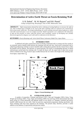
A stabilized wall when constructed in front of already constructed wall or existing rock face results in
an extremely narrow backfill width between the retaining wall and rock face. Such newly constructed wall is
called Fascia Retaining wall.Due to narrow backfill width, arching theory predicts that the vertical forces within
the backfill will be reduced. The decrease in vertical pressure will result in corresponding decrease in lateral
earth pressure exerted upon the retaining wall. To study the fascia wall, the aspect ratio is taken into account
which is defined as the ratio of narrow space (width) between the two walls to the height of the retaining wall.
From figure, Aspect Ratio = .
Figure 1 Fascia Retaining wall
II. LITERATURE SURVEY
A number of researchers: Frydman and Keissar (1987), Take and Valsangkar (2001), Kniss, Yang,
Wright and Zornberg (2007), Yang, Gupta and Zornberg (2009), Fan and Fang (2010) demonstrated that earth
thrust acting on a Fascia Retaining wall depends mainly on two factors viz. boundary constraint and narrow
backfill width between the two walls. Only two previous experimental programmes dealing specifically with
fascia retaining walls have been reported in the literature. The present study, therefore, provides a useful
addition to the database of experimental earth pressure studies.
2. Determination Of Active Earth Thrust On…
www.ijesi.org 58 | Page
Take and Valsangkar (2001) performed a series of centrifuge tests to study the factors affecting the
calibration of subminiature boundary pressure cells to investigate the reduction in lateral earth pressure within
the narrow backfill width of an unyielding fascia retaining wall. Frydman and Keissar (1987) presented the
study of the lateral pressure transferred to a rigid retaining wall by granular fill confined between the wall and
an adjacent rock face. They found that a pressure acting on the wall, when it reaches an active condition by
rotating about its base, appears to be less sensitive to small variations in placement conditions. Yang and Liu
(2007) studied earth pressure acting on the narrow retaining walls by Finite element analysis. The trend of
decrease of earth pressures as the decrease of wall aspect ratios was observed. When aspect ratio is L/H < 0.3,
the failure mode is found to transform from internal failure to external failure. Kuo-Hsin Yang and J.G.
Zornberg ( 2009) have discussed the limit equilibrium method to calculate the earth pressure on fascia retaining
wall. Leshchinsky, Hu, and Han (2003) and Lawson and Yee (2005) performed limit equilibrium analyses to
study the effects of wall aspect ratio on the horizontal earth pressure coefficients.
Theoretical Formulation of the Problem
Calculation for Earth Thrust is made by using Analytical Solution by considering various forces acting
on the failure wedge and calculating the location of critical failure wedge with respect to horizontal. The earth
thrust corresponding to this critical wedge will give maximum earth thrust acting on the wall. The calculation is
done by smooth retaining wall with no wall friction angle (δ = 0̊).
Figure 2. Forces Acting on the Failure Wedge
Figure 2 represents, the various forces acting on the failure wedge. As the wall is considered to be
smooth the active earth thrust force will act horizontally on the retaining wall. The various parameters shown in
figure are as explained below:
EA = Active Earth Thrust in kN
R = Resultant Force acting at right angles to failure wedge in kN
W = weight of soil within the failure wedge in kN
ρ = angle made by failure wedge with horizontal in degrees
ɸ = angle of internal friction of soil in degrees
H = height of the retaining wall in metres
B = width of backfill soil between the retaining wall and unyielding wall
X1 and X2 = angles made by resultant w.r.t horizontal and vertical respectively
By considering the geometry of failure wedge as shown in Fig. 2, the expression for earth thrusts is
obtained as follows:
Angle, X1= [180̊ - (boc + cbo)]
= {180̊ - [ρ + (90 - ɸ)]}
= 180̊ - ρ – 90 + ɸ
Angle, X1 = 90̊ - (ρ - ɸ)
Also, X1 + X2 = 90̊
X2 = 90̊ - X1
X2 = 90̊ - (90̊ - ρ + ɸ)
Angle, X2 = (ρ - ɸ)
3. Determination Of Active Earth Thrust On…
www.ijesi.org 59 | Page
From the three forces namely W, EA and R
180̊ = X3 + 90̊ + X2
180 = X3+ 90̊ + (ρ - ɸ)
X3 = 90 – ρ + ɸ
Angle, X3 = 90̊ - (ρ - ɸ)
Now to calculate the value of magnitudes of forces: -
From Sine Rule, We have
=
EA = W x
Therefore, EA = W x
EA = W x
EA = W x tan (ρ - ɸ)
Above equation represents the Earth thrust value which can be calculated either by differentiating
above equation w.r.t „ρ‟ value and equating it to zero or by taking various values of „ρ‟ and calculating the
corresponding value of earth thrust. The value of „ρ‟ which gives maximum value of Earth thrust should be used
for design of such walls. In this study the earth thrust is calculated by taking various values of „ρ‟.
Experimental Investigation
Selection of Soil Sample
Grain size distribution affects the behavior of sand masses during backfilling. The cohesionless dry
sand is critical for its earth pressure behavior against retaining wall. Hence cohesionless dry sand is selected
whose properties are discussed in Table 1
Table1. Index Properties of Clean Sand
Sr.No. Index Properties Values
1. Density ρ 1.99 gm/cc
2. Specific Gravity G 2.726
3. Coefficient of Curvature Cc 0.868
4. Coefficient of Uniformity Cu 3.235
5. Phi, ɸ 32.85
6. emax 0.6285
7. emin 0.3806
Experimental set up
The experimental set up consists of a retaining wall model comprises of a retaining wall of MS plate
(1210 x 1000 x 5) mm size fixed at the bottom by using bolting arrangement, unyielding wall of same size
which is held immobile by fixing it to a grooving arrangement made at five different locations, LVDT
arrangement is to measure horizontal displacement of wall. 5 LVDT‟s are used; 3 in the same line at the top
(800mm), one at the center (400mm) and one at the bottom (200mm), Displacement display unit to display the
deflection of retaining wall after backfilling the sand in the model tank.
4. Determination Of Active Earth Thrust On…
www.ijesi.org 60 | Page
All the components of the model retaining wall are shown in the Figure 3.
Figure 3. Retaining wall Model
Testing Program
Ten tests in total (cf. Table 2) are conducted on the retaining wall model to study the
effect of aspect ratio on the calculated earth thrust. Tests are planned for different aspect ratio
ranging from 0.25 to 1.25.
Table 2 Testing Program
Sr. No. Retaining Wall
Dimensions
Aspect Ratio
(L/H)
Test Condition
01.
(1000 x 1210 x 5) mm
0.25
Full Backfill with 0.8m Height
02.
0.50
Full Backfill with 0.8m Height
03.
0.75
Full Backfill with 0.8m Height
04.
1.00
Full Backfill with 0.8m Height
05.
1.25
Full Backfill with 0.8m Height
RW Model
Backfill Material
LVDT‟s to measure
deflection
Wall under earth
pressure Unyielding Wall
5. Determination Of Active Earth Thrust On…
www.ijesi.org 61 | Page
III. RESULTS AND DISCUSSION
The experimental work was carried out in order to study the effect of Aspect Ratio on evaluated earth
thrust on retaining wall model. For this purpose total five tests were conducted on dry Cohesionless soil for full
backfill with 0.8 m height for different Aspect Ratios ranging from 0.25 to 1.25. All the tests were conducted
over a smooth retaining wall for no wall friction angle i.e., δ = 0 ̊.
(a) For Aspect Ratio = 0.25
The Aspect Ratio is kept as 0.25 by changing the position of unyielding wall and placing it at a
distance of 0.25 from retaining wall (RW) so that the ratio of L/H = 0.25. The values of deflection of RW only
due to backfill are taken by fixing the LVDT‟s over the height of RW at three different locations.
Figure 4. Deflections at various levels
Figure 4 shows the plot of displacement of wall (mm) versus backfill height (mm). The three curve
lines of green, orange and blue colour represent the deflection curve for bottom, middle and top location of
LVDT‟s The maximum deflection values of 9.43 mm, 5.00 mm and 1.10 mm are observed at top,
middle and bottom location of LVDT‟s respectively; up to a height of 150 mm, wall does not deflect
significantly. The deflection of wall for a height up to 400 mm at middle level is slightly less than that at the top
level and it is about 0.82 times the deflection at top level. The variation in deflection values for three different
locations increases as the backfill height increased. The maximum deflection values observed at a height of 800
mm at bottom and middle location are about 0.12 and 0.53 times deflection at top level. Similar readings were
taken for other aspect ratios and the displacement of the wall was measured for backfill heights with the interval
of 0.1m. For aspect ratio of 0.5,it is observed that maximum deflection values at top, middle and bottom location
of LVDT‟s are 11.80 mm, 6.80 mm and 2.70 mm respectively, up to a height of 250 mm value deflection of
wall is observed to be very negligible and all three curves more or less merge with each other. The wall
deflection can be observed clearly in the graph from a wall height of 300 mm and above. The deflection of wall
for a height of 400 mm at bottom level and middle level is slightly less than the top level and it is about 0.41 and
0.68 times the deflection at top level. The deflection of wall from height of 600 mm at middle level is observed
to vary from 0.50 to 0.58 times the top deflection whereas it is found to be 1.82 to 2.5 times the bottom
deflection. Similarly for aspect ratio 0.75, the maximum deflection values recorded were 16.50 mm, 9.20 mm
and 4.00 mm at top, middle and bottom location of LVDT‟s respectively. No deflection is observed for a
backfill height of 100 mm. The wall deflection observed up to a height of 300 mm is less than 1 mm.
6. Determination Of Active Earth Thrust On…
www.ijesi.org 62 | Page
The deflection of wall for a height of 400 mm at bottom and middle level is less than the top level and
it is about 0.16 and 0.58 times the deflection at top level respectively. The deflection of wall from height of 600
mm at middle level is observed to varies from 0.73 to 0.50 times the top deflection whereas it varies from 1.81
to 2.3 times the bottom deflection.The maximum deflection values were 18.40 mm, 8.90 mm and 5.90 mm at
top, middle and bottom location of LVDT‟s respectively for aspect ratio =1. The wall deflection observed up to
a height of 300 mm continues to be less than 1 mm. The deflection of wall at a height equal to half the height of
wall is nearly the same at all locations of LVDT‟s and it can be seen from graph that up to the backfill height
equal to 400 mm all three curves are coinciding with each other. The deflection of wall from height of 600 mm
at middle level is observed to
vary from 0.79 to 0.48 times the top deflection whereas it varies from 1.84 to 1.51 times the bottom
deflection.
(b) For Aspect Ratio = 1.25
Figure 5 Deflections at various levels
It is observed from figure 5, that maximum deflection values of 21.23 mm, 9.60 mm and 6.50 mm is
observed at top, middle and bottom location of LVDT‟s respectively. The wall deflection up to a height of 300
mm is nearly the same at all location of LVDT‟s and thus all the three curves coincide with each other. The
deflection of wall at top level is more and the variation of values from middle and bottom level is more. The
deflection value at top level is 2.38 to 2.21 times that at the centre deflection whereas it varies from 8.92 to 3.27
times the bottom level deflection for height of 400 mm to 800 mm. The maximum deflection values at bottom
and middle level of LVDT‟s are 0.31 and 0.45 times the top level LVDT‟s deflection values.
Calculation of Earth Thrust from Experimentation Values
Earth Thrust is calculated by using deflections values observed during experiment conducted on the
model developed in the laboratory. The earth thrust is calculated for each of the aspect ratios considered in the
present work. The results obtained from experimental values are compared with those obtained by using
analytical method and are tabulated as below.
Table 3 Comparison of Earth Thrust Values
Sr. No. Aspect
ratio
EA (kN)
(Theoretical)
EA (kN)
(Experimental)
Tolerance
(%)
1 0.25 1.721 1.685 2.09
2 0.50 1.888 1.797 4.82
3 0.75 1.888 1.833 2.91
4 1.00 1.888 1.865 1.22
5 1.25 1.888 1.879 0.48
7. Determination Of Active Earth Thrust On…
www.ijesi.org 63 | Page
IV. CONCLUSION
A methodology is developed for design purposes to estimate the earth pressure on fascia retaining wall
which is then verified by model tests and the tolerance is remarkable, demonstrating that the proposed method
can be applied for designing such walls in the field.
REFERENCES
[1] Kniss, K.T., Yang, K.H., Wright, S.G., and Zornberg , J.G., (2007), “Earth Pressures and Design Considerations of Narrow MSE
Walls,” ASCE TEXAS Section, Spring Term, April
[2] Fan, C.C., Fang, Y.S., (2010), “Numerical Solution of Active Earth Pressures on Rigid Retaining Walls Built Near Rock Face,”
Journal of Computers and Geotechnics, Vol. 37, August, pp. 1023 - 1029
[3] Yang, K.H., Ching, J., and Zornberg, J.G., (2011), “Reliability-Based Design for External Stability of Narrow Mechanically
Stabilized Earth Walls: Calibration from Centrifuge Tests,” Journal of Geotechnical and Geoenvironmental Engineering, ASCE,
Vol. 137, No. 3, March, pp. 239 - 253
[4] Yang, K.H., and Liu, C. N., (2007),“Finite Element Analysis of Earth Pressures for Narrow Retaining Walls,” Journal of
GeoEngineering, Vol. 2, No. 2, August, pp. 43 - 52
[5] Yang, K.H., Gupta, Ranjiv, and Zornberg, J.G., (2009), “Location of Failure Plane within Narrow GRS Wall Systems”,
Geosynthetics, February.
[6] Li, L., Aubertin, M., Simon, R., Bussière, B., and Belem, T., (2003), “Modeling Arching Effects in Narrow Backfilled Stopes with
FLAC”, FLAC and Numerical Modeling in Geomechanics – 2003, Balkema, Rotterdam: pp. 211-219.
[7] O’Neal, T. S., and Hagerty, D.J, (2011), “Earth Pressure in Confined Cohesion less Backfill against Tall Rigid Walls – a case
History”, Canadian Geotechnical Journal, Vol. 48, March, pp. 1188 – 1197.
[8] Li, L., Aubertin, M., (2007),“An Improved Solution to Estimate the Stress State In Sub-Vertical Backfilled Stopes”, OttawaGeo,
April.
[9] Handy, R. L., (1985), “The Arch In Soil Arching”, Journal of Geotechnical Engineering, ASCE, Vol. 111, No. 3, March, pp. 302 –
318.
[10] Take, W.A., and Valsangkar, A. J., (2001),“Earth Pressures on Unyielding Retaining Walls of Narrow Backfill Width”, Canadian
Geotechnical Journal, Vol. 38, June, pp. 1220 – 1230
[11] Frydman, S., and Keissar, I., (1987), “Earth Pressure on Retaining Walls Near Rock Faces”, Journal Geotechnical Engineering,
Vol. 113, No. 6, June, pp. 586 – 599
[12] Janssen, H. A.,(1985), “ Versuche uber Getreidedruck in Silozellen, Aeitsc hri fi, Verein Deutscher Ingenieure”,Partial English
translation in Proceedings of Institute of Civil Engineen, London, England , Vol. 39, pp. 1045- 1049.
[13] Paik, K.H., and Salgado, R., (2003), “Estimation of active earth pressure against rigid retaining walls considering arching
effects”, Geotechnique, Vol. 7, pp. 643 - 653.
[14] Yang, K.H., and Zornberg, J. G., (2001),“The coefficient of Earth Pressure on Retaining Walls Placed in Front of a Stable Face
with Limited Space”, University of Texas at Austin .
![Determination Of Active Earth Thrust On…
www.ijesi.org 58 | Page
Take and Valsangkar (2001) performed a series of centrifuge tests to study the factors affecting the
calibration of subminiature boundary pressure cells to investigate the reduction in lateral earth pressure within
the narrow backfill width of an unyielding fascia retaining wall. Frydman and Keissar (1987) presented the
study of the lateral pressure transferred to a rigid retaining wall by granular fill confined between the wall and
an adjacent rock face. They found that a pressure acting on the wall, when it reaches an active condition by
rotating about its base, appears to be less sensitive to small variations in placement conditions. Yang and Liu
(2007) studied earth pressure acting on the narrow retaining walls by Finite element analysis. The trend of
decrease of earth pressures as the decrease of wall aspect ratios was observed. When aspect ratio is L/H < 0.3,
the failure mode is found to transform from internal failure to external failure. Kuo-Hsin Yang and J.G.
Zornberg ( 2009) have discussed the limit equilibrium method to calculate the earth pressure on fascia retaining
wall. Leshchinsky, Hu, and Han (2003) and Lawson and Yee (2005) performed limit equilibrium analyses to
study the effects of wall aspect ratio on the horizontal earth pressure coefficients.
Theoretical Formulation of the Problem
Calculation for Earth Thrust is made by using Analytical Solution by considering various forces acting
on the failure wedge and calculating the location of critical failure wedge with respect to horizontal. The earth
thrust corresponding to this critical wedge will give maximum earth thrust acting on the wall. The calculation is
done by smooth retaining wall with no wall friction angle (δ = 0̊).
Figure 2. Forces Acting on the Failure Wedge
Figure 2 represents, the various forces acting on the failure wedge. As the wall is considered to be
smooth the active earth thrust force will act horizontally on the retaining wall. The various parameters shown in
figure are as explained below:
EA = Active Earth Thrust in kN
R = Resultant Force acting at right angles to failure wedge in kN
W = weight of soil within the failure wedge in kN
ρ = angle made by failure wedge with horizontal in degrees
ɸ = angle of internal friction of soil in degrees
H = height of the retaining wall in metres
B = width of backfill soil between the retaining wall and unyielding wall
X1 and X2 = angles made by resultant w.r.t horizontal and vertical respectively
By considering the geometry of failure wedge as shown in Fig. 2, the expression for earth thrusts is
obtained as follows:
Angle, X1= [180̊ - (boc + cbo)]
= {180̊ - [ρ + (90 - ɸ)]}
= 180̊ - ρ – 90 + ɸ
Angle, X1 = 90̊ - (ρ - ɸ)
Also, X1 + X2 = 90̊
X2 = 90̊ - X1
X2 = 90̊ - (90̊ - ρ + ɸ)
Angle, X2 = (ρ - ɸ)](data:image/gif;base64,R0lGODlhAQABAIAAAAAAAP///yH5BAEAAAAALAAAAAABAAEAAAIBRAA7)