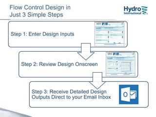
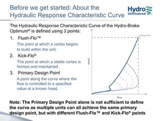
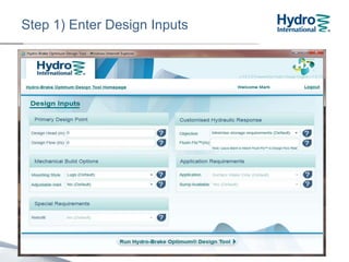
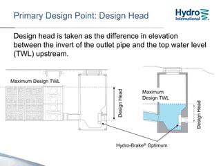
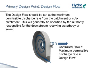
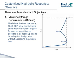
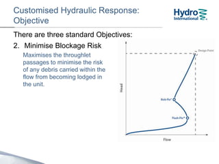
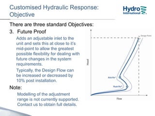
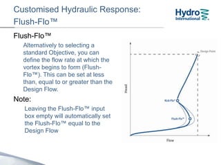
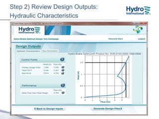
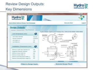
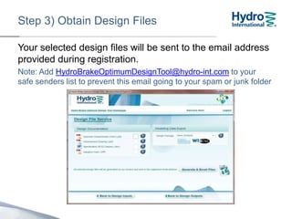
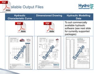
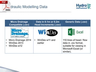
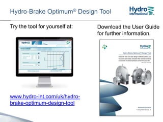
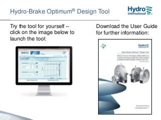
Hydro-Brake Optimum®
Design Tool
Step by Step Guide
Flow Control Design in
Just 3 Simple Steps
Step 1: Enter Design Inputs
Step 2: Review Design Onscreen
Step 3: Receive Detailed Design
Outputs Direct to your Email Inbox
Registration / Login
• On first use, you will be invited to Register and will be
able to use the tool straight away
• On subsequent visits, log in using the User Name and
Password supplied during Registration
If you forget your User
Name or Password,
contact the Design Tool
Support Hotline on:
01275 337957
Before we get started…
About the Hydraulic Response Characteristic Curve
The Hydraulic Response Characteristic Curve of the Hydro-Brake
Optimum® is defined using 3 points:
1. Flush-Flo™
The point at which a vortex begins
to build within the unit.
2. Kick-Flo®
The point at which a stable vortex is
formed and maintained
3. Design Point
A point along the curve where the
flow is controlled to a specified
value at a known head.
Note: The Design Point alone is not sufficient to define the curve.
Many different units with different Flush-Flo™ and Kick-Flo®
points can all achieve the same primary design point.
A word about tooltips
If you get stuck at any point, hold your mouse cursor over
any icon for a short tip
Step 1) Enter Design Inputs
Design head is taken as the difference in elevation
between the invert of the outlet pipe and the top water level
(TWL) upstream.
The maximum Design Head is 4m.
DesignHead
Primary Design Point: Design Head
Hydro-Brake® Optimum
Maximum
Design TWL
Maximum Design TWL
DesignHead
Primary Design Point: Design Flow
The Design Flow should be set at the maximum
permissible discharge rate from the catchment or sub-
catchment. This will generally be specified by the authority
responsible for the downstream receiving waterbody or
sewer.
The maximum Design Flow is 250 l/s.
Controlled Flow =
Maximum permissible
discharge rate =
Design Flow
Customised Hydraulic Response:
Objective
1. Minimise Storage
Requirements (Default)
Maximises the flow rate at the
Flush-Flo® point and the head
at the Kick-Flo™ point to pass
forward as much flow as
possible at all heads up to and
including the head at the
Design Point (Design Head)
without exceeding the design
flow.
There are three standard Objectives:
Customised Hydraulic Response:
Objective
2. Minimise Blockage Risk
Maximises the clearances
through the unit to minimise
the risk of any debris carried
within the flow from becoming
lodged in the unit.
There are three standard Objectives:
Customised Hydraulic Response:
Objective
3. Future Proof
Adds an adjustable inlet to the
unit and sets this at close to its
mid-point to allow the greatest
possible flexibility for dealing with
future changes in the system
requirements.
Typically, the Design Flow can
be adjusted by 20% post
installation.
Note:
Modelling of the adjustment
range is not currently supported.
Contact us to obtain full details.
There are three standard Objectives:
Customised Hydraulic Response:
Flush-Flo™
Flush-Flo™
Alternatively to selecting a
standard Objective, you can
define the flow rate at which the
vortex begins to form (Flush-
Flo™). This can be set at less
than, equal to or greater than the
Design Flow.
Note:
Leaving the Flush-Flo™ input
box empty will automatically set
the Flush-Flo™ equal to the
Design Flow
Mechanical Build Options:
Mounting Style
Select your desired standard mounting style:
Note: Some mounting styles may not be available for particular design
inputs. Contact us for bespoke mounting solutions or off-site solutions.
Mounting Plate
(Flat or Curved)
Push-Fit Spigot Mounting Lugs
(Default)
Mechanical Build Options:
Adjustable Inlet
Units can be supplied with or without an adjustable inlet.
Flow rates can typically be adjusted by 20% post
installation.
Note: Future Proof Objective requires an adjustable inlet
Step 2) Review Design Outputs:
Hydraulic Characteristics
Review Design Outputs:
Key Dimensions
Site Specific Design (SSD)
For larger units, non standard
chamber constructions may be
required.
Under these conditions, the
Design Tool will not automatically
generate all of installation
dimensions.
Contact us for advice on chamber
construction.
Step 3) Obtain Design Files
Your selected design files will be sent to the email address
provided during registration.
Note: Add HydroBrakeOptimumDesignTool@hydro-int.com to your
safe senders list to prevent this email going to your spam or junk folder
Available Output Files
Hydraulic
Characteristic Curve
Dimensioned Drawing Hydraulic Modelling
Data
To suit commercially
available hydraulic
software (see next slide
for currently supported
packages)
Hydraulic Modelling Data
Micro Drainage
Compatible (.csv)
Data in 0.1m or 0.2m
Head Increments (.csv)
Generic Data (.csv)
• Micro Drainage 2014
• WinDes 2013
• WinDes w12
• WinDes w11 and
earlier
110 lines of head / flow
data in .csv format,
suitable for viewing in
Microsoft Excel (or
similar).
After requesting design files, you can continue to use the
Design Tool, which will generate your files in the
background.
Please do not log out or exit your browser until the
Design File Email Request Acknowledgement is
shown.
Design File Email Request
Acknowledgement
Hydro-Brake Optimum® Design Tool
Try the tool for yourself –
click on the image below to
launch the tool:
Download the User Guide
for further information:
Thank you
01275 337937
Email: enquiries@hydro-int.com

Hydro Brake Optimum Design Tool - Step by Step Guide

  • 1.
  • 2.
    Flow Control Designin Just 3 Simple Steps Step 1: Enter Design Inputs Step 2: Review Design Onscreen Step 3: Receive Detailed Design Outputs Direct to your Email Inbox
  • 3.
    Registration / Login •On first use, you will be invited to Register and will be able to use the tool straight away • On subsequent visits, log in using the User Name and Password supplied during Registration If you forget your User Name or Password, contact the Design Tool Support Hotline on: 01275 337957
  • 4.
    Before we getstarted… About the Hydraulic Response Characteristic Curve The Hydraulic Response Characteristic Curve of the Hydro-Brake Optimum® is defined using 3 points: 1. Flush-Flo™ The point at which a vortex begins to build within the unit. 2. Kick-Flo® The point at which a stable vortex is formed and maintained 3. Design Point A point along the curve where the flow is controlled to a specified value at a known head.
  • 5.
    Before we getstarted… About the Hydraulic Response Characteristic Curve The Hydraulic Response Characteristic Curve of the Hydro-Brake Optimum® is defined using 3 points: 1. Flush-Flo™ The point at which a vortex begins to build within the unit. 2. Kick-Flo® The point at which a stable vortex is formed and maintained 3. Design Point A point along the curve where the flow is controlled to a specified value at a known head. Note: The Design Point alone is not sufficient to define the curve. Many different units with different Flush-Flo™ and Kick-Flo® points can all achieve the same primary design point.
  • 6.
    A word abouttooltips If you get stuck at any point, hold your mouse cursor over any icon for a short tip
  • 7.
    Step 1) EnterDesign Inputs
  • 8.
    Design head istaken as the difference in elevation between the invert of the outlet pipe and the top water level (TWL) upstream. The maximum Design Head is 4m. DesignHead Primary Design Point: Design Head Hydro-Brake® Optimum Maximum Design TWL Maximum Design TWL DesignHead
  • 9.
    Primary Design Point:Design Flow The Design Flow should be set at the maximum permissible discharge rate from the catchment or sub- catchment. This will generally be specified by the authority responsible for the downstream receiving waterbody or sewer. The maximum Design Flow is 250 l/s. Controlled Flow = Maximum permissible discharge rate = Design Flow
  • 10.
    Customised Hydraulic Response: Objective 1.Minimise Storage Requirements (Default) Maximises the flow rate at the Flush-Flo® point and the head at the Kick-Flo™ point to pass forward as much flow as possible at all heads up to and including the head at the Design Point (Design Head) without exceeding the design flow. There are three standard Objectives:
  • 11.
    Customised Hydraulic Response: Objective 2.Minimise Blockage Risk Maximises the clearances through the unit to minimise the risk of any debris carried within the flow from becoming lodged in the unit. There are three standard Objectives:
  • 12.
    Customised Hydraulic Response: Objective 3.Future Proof Adds an adjustable inlet to the unit and sets this at close to its mid-point to allow the greatest possible flexibility for dealing with future changes in the system requirements. Typically, the Design Flow can be adjusted by 20% post installation. Note: Modelling of the adjustment range is not currently supported. Contact us to obtain full details. There are three standard Objectives:
  • 13.
    Customised Hydraulic Response: Flush-Flo™ Flush-Flo™ Alternativelyto selecting a standard Objective, you can define the flow rate at which the vortex begins to form (Flush- Flo™). This can be set at less than, equal to or greater than the Design Flow. Note: Leaving the Flush-Flo™ input box empty will automatically set the Flush-Flo™ equal to the Design Flow
  • 14.
    Mechanical Build Options: MountingStyle Select your desired standard mounting style: Note: Some mounting styles may not be available for particular design inputs. Contact us for bespoke mounting solutions or off-site solutions. Mounting Plate (Flat or Curved) Push-Fit Spigot Mounting Lugs (Default)
  • 15.
    Mechanical Build Options: AdjustableInlet Units can be supplied with or without an adjustable inlet. Flow rates can typically be adjusted by 20% post installation. Note: Future Proof Objective requires an adjustable inlet
  • 16.
    Step 2) ReviewDesign Outputs: Hydraulic Characteristics
  • 17.
  • 18.
    Site Specific Design(SSD) For larger units, non standard chamber constructions may be required. Under these conditions, the Design Tool will not automatically generate all of installation dimensions. Contact us for advice on chamber construction.
  • 19.
    Step 3) ObtainDesign Files Your selected design files will be sent to the email address provided during registration. Note: Add HydroBrakeOptimumDesignTool@hydro-int.com to your safe senders list to prevent this email going to your spam or junk folder
  • 20.
    Available Output Files Hydraulic CharacteristicCurve Dimensioned Drawing Hydraulic Modelling Data To suit commercially available hydraulic software (see next slide for currently supported packages)
  • 21.
    Hydraulic Modelling Data MicroDrainage Compatible (.csv) Data in 0.1m or 0.2m Head Increments (.csv) Generic Data (.csv) • Micro Drainage 2014 • WinDes 2013 • WinDes w12 • WinDes w11 and earlier 110 lines of head / flow data in .csv format, suitable for viewing in Microsoft Excel (or similar).
  • 22.
    After requesting designfiles, you can continue to use the Design Tool, which will generate your files in the background. Please do not log out or exit your browser until the Design File Email Request Acknowledgement is shown. Design File Email Request Acknowledgement
  • 23.
    Hydro-Brake Optimum® DesignTool Try the tool for yourself – click on the image below to launch the tool: Download the User Guide for further information:
  • 24.
    Thank you 01275 337937 Email:enquiries@hydro-int.com

Editor's Notes

  • #23 USE THIS SLIDE IF HBO TOOL DEMO DOESN’T WORKWait for design file acknowledgement.Logging out or closing internet browser may interrupt file generation.Remember to add email address to address book / safe senders list or check spam / junk folder.