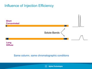
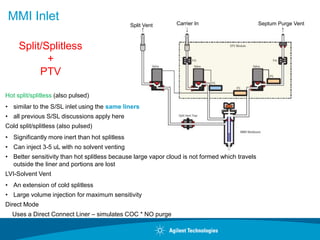
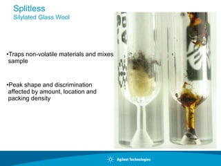
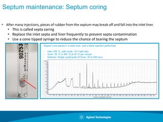
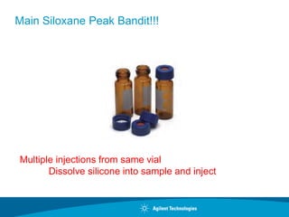
What’s going on in there anyway & how do I stay in
control?
Understanding your GC
Inlet and How to Maintain it.
Simon Jones
CSD Application Engineer
SAMPLE INJECTION
Goals
•Introduce sample into the column
•Reproducible
•No efficiency losses
•Representative of sample
Influence of Injection Efficiency
Short
Concentrated
Long
Diffuse
Solute Bands
Same column, same chromatographic conditions
Inlet Choices
Inlet Column Mode
Sample
Concentration
Comments
Sample to
Column
Split / Splitless Capillary
Split
Purged Split
Splitless
Purged Splitless
High
High
Low
Low
Most commonly
used inlet. Very
Flexible
Very Little
Very Little
All
All
Cool-On-Column Capillary N/A Low or labile
Minimal
discrimination and
decompositoin
All
Packed
Packed
Large Capillary
N/A
N/A
Any
Any
OK if resolution is
not critical
All
All
Programmed
Temperature
Vaporizaton
Capillary
Split
Pulsed Split
Splitless
Pulsed Splitless
Solvent Vent
High
High
Low
Low
Low
Not great for HOT
injections.
Can concentrate
analytes and vent
solvent
Very Little
Very Little
All
All
Most
Volatiles
Interface
Capillary
Direct
Split
Splitless
Low
High
Low
Purge & Trap /
Headspace
All
Very Little
All
Multi-Mode Capillary
Split
Pulsed Split
Splitless
Pulsed Splitless
Solvent Vent
High
High
Low
Low
Low
Flexibility of
standard S/SL inlet
and PTV
Very Little
Very Little
All
All
Most
Split/Splitless Inlet Schematic and Operation modes
Modes
• Split
• Pulsed Split (useful for small number of applications)
• Splitless
• Pulsed Splitless
Page 6
Split Injections - Considerations
Dirty Samples are OK - backflushing
Wide Analyte Boiling Range
Solvent Properties
• Wide Boiling Point Range
• Wide Polarity Range
Discrimination can be due to liner or inlet temperature
Most efficient sample transfer = nice sharp peaks
Page 7
Split Injections - Inertness
More inert than splitless
• Higher velocity through the inlet
• Less exposure to inlet hardware
Glass wool is a compromise
• Exhibits some activity
• Greatly improves fluidic performance – mixing of the
vaporized sample is important for uniform splitting
Page 8
Split Injections - recommended Liners
Agilent p/n 5190-2295
Wiped needle improves
• precision
• peak shape
• discrimination
Page 9
Split Injections - Maximizing Sensitivity
Increase Injection Volume
• liner dependent (use the Pressure-Volume Calculator)
• 2 uL maximum
Reduce Split Ratio
• go from 50:1 to 10:1
• 10:1 practical lower limit for liquid injections (for 250 - 320 um i.d. columns)
• 1:1 possible for gas injections with correct liner
• Keep TOTAL INLET FLOW at 20 mL/min or higher
Split Injector
Injection Volume
DB-1, 15 m x 0.25 mm I.D., 0.25 µm
60°C for 1 min, 60-180°C at 20°/min; Helium at 30 cm/sec
1. n-heptane 2. toluene 3. n-decane 4. n-butylbenzene 5. n-tridecane
1 2 3 4 5 6
Time (min.)
1 2 3 4 5 6
Time (min.)
1
2
3
4
5
1
2
3
4
5
1 µL 3 µL
1
2
3
Actual
Expected
Minimum Recommended Split Ratio
mm I.D. Lowest ratio
0.10 1:50 - 1:75
0.18 - 0.25 1:10 - 1:20
0.32 1:8 - 1:15
0.53 1:2 - 1:5
Higher
flow
rates
Page 12
Split Injections - Troubleshooting
Column pressures <10 psi
• The pressure pulse from evaporating solvent can cause
discrimination and poor precision
Liner residence times < 0.5 sec (> 200 ml/min)
• poor mixing will cause discrimination
No glass wool
Solvents with high expansion ratio
Column position - top to bottom, side to side
Large bore, short columns with a high split ratio
Backflash
High Ratio Low Ratio
Sample into Column Low High
Efficiency High Low
Discrimination High Low
Carrier Gas use High Low
Split Ratio Comparison
Splitless Injection Overview
•For trace level analysis.
•Use split/splitless injection port in the splitless mode (split vent closed).
•The dilute sample is injected, the sample is volatilized, and majority of
analytes condense on column.
•Later, the split vent is opened and residual solvent is vented.
•Timing, carrier and split vent flows, and oven temperature program are
important.
•Sample has longer residence time in the heated inlet giving more
opportunity to vaporize high boiling sample components compared to split
injection.
Page 15
Splitless Injections - Considerations
Dirty samples are OK - backflushing
Analyte Boiling Range - Wide (but narrower than split)
• early eluters need bp difference vs solvent
Solvent Properties
• Wide Boiling Point Range
– but consider bp of earliest eluting analyte
• Wide Polarity Range (but narrower than split)
– Water and Methanol worst choices
Greater Sample Residence Time
Lower Inlet Temperatures can be used
Better for Labile Compounds
Page 16
Splitless Injections - Inertness
Less inert than COC
• liner and inlet interaction
Less inert than Split
• longer residence time in inlet and on glass wool
• used for trace analysis, so there’s a greater
chance of analyte loss
Page 17
Splitless Injections - Discrimination
Improper purge time
• short purge times cause loss of late eluters
• long purge times cause solvent tail interference with early
eluters
Improper initial oven temp
• too high of a temp prevents solvent effect and a loss of early
eluters
• too low of a temp extends run time
Page 18
Purge time too
long results in
large solvent
tail
Splitless Injections – Splitless Time
(purge time on)
0.75 min purge
time clips
solvent tail
Splitless Injector
Injection Volume
DB-1, 15 m x 0.25 mm I.D., 0.25 µm
60°C for 1 min, 60-180°C at 20°/min; Helium at 30 cm/sec
1. n-decane 2. n-dodecane 3. n-tetradecane 4. n-hexadecane
2 4 6 8
Time (min.)
2 4 6 8
Time (min.)
1 µL 3 µL
1
2 3 4
1 2 3
4
1
2
3
Actual
Expected
Splitless Injector
Injector Temperature
DB-1, 15 m x 0.25 mm I.D., 0.25 µm
50°C for 0.5 min, 50-325°C at 20°/min; Helium at 30 cm/sec
Phthalates: 1. dimethyl 2. diethyl 3. dibutyl 4. benzylbutyl 5.bis(2-ethylhexyl) 6. dioctyl
200°C 250°C
0 2 4 6 8 10 12 14
Time (min.)
0 2 4 6 8 10 12 14
Time (min.)
1
2 3
4
5
6
1
2
3
4
5
6
Splitless Injector
Sample Re-focusing
Sample re-focusing improves efficiency
Use low column temperature to refocus solvent
- called the solvent effect
Use cold trapping
Splitless Sample Re-focussing
• Sample refocusing
• Also known as the “solvent effect”
• Condenses sample as a thin film on the head of the column
• Initial oven temperature must be at least 10 °C below the solvent B.P.
• Increases separation efficiency and resolution and better peak shape
• Especially for low boiling analytes
• “Cold trapping” is a version of sample re-focusing for high boiling analytes
• Occurs when the starting oven temperature is 150 °C below the boiling point of
analytes of interest
• Condenses the analytes on the head of the column
• Results in better peak shapes
• Solvent effect and cold trapping can occur in same sample
• When looking at analytes with a wide distribution of B.P.s
Splitless Injector
Solvent Effect
Solvent and
solutes
Solvent film
1.
2.
3.
4.
Initial column temperature at
least 10°C below sample
solvent boiling point
Required to obtain good peak
shapes unless cold trapping
occurs
Rule of thumb, if solute BP
>150°C above initial column
temperature, the solute will
cold trap
Cold trapping has greater
efficiency than solvent effect
Splitless Injector
Initial Column Temperature
Hexane Solvent (BP = 68-69°C)
DB-1, 15 m x 0.25 mm I.D., 0.25 µm
50°C or 70°C for 0.5 min, to 210°C at 20°/min; Helium at 30 cm/sec
1. n-decane 2. n-dodecane 3. n-tetradecane 4. n-hexadecane
2 4 6 8
Time (min.)
50°C
1
2 3 4
2 4 6 8
Time (min.)
70°C
1
2
3 4
Solvent Effect Cold Trapping
Splitless Injector
Reverse Solvent Effect/Polarity Miss-Match
DB-1, 15 m x 0.25 mm I.D., 0.25 µm
50°C for 1 min, 50-210°C at 20°/min; Helium at 30 cm/sec
1. 1,3-DCP 2. 3-hexanol 3. butyl acetate 4. 1-heptanol 5. 3-octanone 6. 1,2-dichlorobenzene
0 1 2 3 4 5 6
Time (min.)
1 2 3 4 5 6
Time (min.)
Hexane Methanol
1
2
3
4
5 6
1
2
3
4
5 6
Retention Gap
Also Called A Guard Column
Usually 2-10 meters long and same diameter as the column
(or larger if needed)
Injector
Detector
Deactivated
Fused Silica
Tubing
Union
Column
Splitless Injector
3 m x 0.25 mm I.D. Retention Gap
DB-1, 15 m x 0.25 mm I.D., 0.25 µm
50°C for 1 min, 50-210°C at 20°/min; Helium at 30 cm/sec
1. 1,3-DCP 2. 3-hexanol 3. butyl acetate 4. 1-heptanol 5. 3-octanone 6. 1,2-dichlorobenzene
4
1 2 3 4 5 6
Time (min.)
Methanol
1
2
3
4
5 6
1 2 3 4 5 6
Time (min.)
Methanol
1
2
3
5 6
No retention gap With retention gap
Page 28
Pulsed Splitless
- sample containment more critical than in split injection
- sharper peaks than in traditional splitless injection
- two new parameters to set:
- pulse pressure and pulse time
EPC for Pulsed Splitless Injection
Pressure Pulse contains sample expansion
and transfers analytes to the column faster.
Typical starting point
- Pulse pressure = double resting pressure
- Tie pulse time to purge time
Page 29
Benefits of the Pulsed Splitless Mode
20
30
40
50
60
70
80
90
100
110
120
70 psi
pulsed splitless
on column
22.5psi
pulsed splitless splitless
Injection Type
%
Recovery
(on
column=100)
Methamidophos
Acephate
Azobenzene
Omethoate
Diazinon
Dimethoate
Chlorpyrifos
High Column Flow
Normal Column Flow
% Recovery of Each Labile Pesticide Relative to
Cool On-Column injection
Page 30
Splitless Injections – Starting Parameters
Injection Volume = 1 uL
– Check the Pressure-Volume Calculator
Initial Oven Temp = 10oC < solvent boiling point
Purge Flow = 20 to 60 mL/min
Purge Time = 0.75 min
– Sweep with 2 liner volumes of carrier gas
No pulse
Try to avoid water and methanol as solvents
Page 31
Splitless Injections – Troubleshooting Tips
Injecting too much
• column overload = poor peak shape
• inlet overload = poor reproducibility
– ghost peaks in subsequent blanks are possible
No glass wool
• poor mixing
• dirt on column
Glass wool
• reacts with trace components
Page 32
Splitless Injections – Troubleshooting Tips
If you think you have an inlet issue related to splitless injections
• Run a 10:1 split injection
• Make up a standard at 10x concentration and run a 10:1 split
injection
When I changed from split to splitless I didn’t see an increase in
response!!!
Verify that the purge time is not set to 0 min. Try increasing
the purge time.
MMI Inlet Carrier In
Split Vent Septum Purge Vent
Hot split/splitless (also pulsed)
• similar to the S/SL inlet using the same liners
• all previous S/SL discussions apply here
Cold split/splitless (also pulsed)
• Significantly more inert than hot splitless
• Can inject 3-5 uL with no solvent venting
• Better sensitivity than hot splitless because large vapor cloud is not formed which travels
outside the liner and portions are lost
LVI-Solvent Vent
• An extension of cold splitless
• Large volume injection for maximum sensitivity
Direct Mode
Uses a Direct Connect Liner – simulates COC * NO purge
Split/Splitless
+
PTV
MultiMode (MMI) Inlet Features
Hardware
Temperature range of -160C to 450C
Heating @ 15C/sec (900C/min)
Septum/Liner Easily Exchangeable using Turn Top Inlet
Injection Modes: Hot S/SL, Cold S/SL, all in pulsed mode, solvent vent mode,
residue removal mode
Support for single stroke injections from 0.1 mL to 250 mL
MultiMode Inlet Solves Many Problems
Performing large volume injection (LVI) of relatively clean samples?
- programmable injection slows solvent evaporation and maximizes analyte
transfer into the column/detector
- decrease MDL by injecting more sample
Injecting dirty samples?
- matrix vent, backflush and easy liner changing minimize dirty sample affects
Performing analyses of high molec. wt. and/or thermally labile
compounds?
- temperature programming of Multimode inlet elutes analytes at the lowest
possible temperature, minimizing breakdown and absorption
- discrimination of high molec. wt. compounds is minimal allowing HT GC
MultiMode GC Inlet - Cold Injections
• No syringe-needle discrimination; Minimal inlet discrimination
• No special syringes, liners or consumables
• Large volume injection (5ul to 250ul) - lower detection limits
• Solvent vent/matrix vent - decrease interference / maintenance
• Flexibility (hot/cold split/splitless, temperature programmed vaporization)
• Cold trapping in liner - improves chromatographic peak shape, resolution
• Capillary column backflush with CFT - decreases cycle time, maintenance
MMI Column Installation
Set to 10-12 mm
Trim the column
Thread the column
into the column adapter –
Stabilize the column adapter
with a 5/16” wrench
Tighten the column
with a 1/4” wrench –
continue to hold the
column adapter
with a 5/16” wrench
• Graphite ferrules
are recommended
over Vespel
GC surfaces that touch the sample
Ultimetal Capillary Flow Technology
Devices, Ultimate Union
GC Column
Inert Gold Seal
Inlet Liner
Ferrules
The Inlet
Root Causes of Inlet Performance Degradation, and
Consequences
Accumulation of Sample Residues
• Loss of response, tailing on active analytes, split vent trap fouling and inaccurate EPC flow
control
Accumulation of Consumables wear particles
• Same as Accumulation of Sample Residues, plus “bleed peaks”
Leak in Septum Nut, Septum
• Damage to O2 sensitive detectors, irreversible damage to column
Non-Optimized Set-up
• O-ring, Gold Seal, Ferrules, Column Nuts
• Faster inlet performance degradation between maintenance sessions
Inlet Liner Troubleshooting
•Many chromatographic problems are blamed on the column.
•Often, a dirty liner is the culprit.
Symptoms include:
Poor peak shape
Irregular baselines
Poor resolution
Poor response
Splitless
Silylated Glass Wool
•Traps non-volatile materials and mixes
sample
•Peak shape and discrimination
affected by amount, location and
packing density
•Liners become contaminated with use,
collecting non-volatiles, salts, excess reagents,
etc., or become damaged/cracked.
•Should inspect and replace liners often.
•Handle with gloves and forceps.
•Insert into or remove liners only from cool
injection ports.
•Replacing with a new liner is recommended, to
ensure reproducibility
Splitless Liner Maintenance
Leak in Septum
Using septa beyond lifetime/temperature recommendations.
•“Use environments” that decrease lifetime include manual injections,
wrong syringe tip type, larger gauge syringes, non-Agilent
Autosamplers (Agilent’s are precisely aligned).
• Septum Type and Syringe Needle type mating are essential to
minimizing leak rate.
Solid Septum
HP-Point Style
CenterGuide Septum
Tips to Maximize Septum Life, Minimize Septum Leaks
– Use Agilent Gold Standard, 23-26 gauge, HP Point taper
syringes. The point style cores septa significantly less when
used with CenterGuide Septa. Taper minimizes septum
coring/wear.
– Use Agilent CenterGuide Septa. The molded hole minimizes
septa coring, counter-intuitive, but true.
Leaks Due to Septum Nut
• With repeated use, conical needle guide gets worn, out of round, and needs
replacement as septum can begin to “bulge” out, especially with excessive
tightening,
• Septa fail faster because needle is not guided with as much precision.
• Under or Over tightening—tighten nut until c-clamp on top stops turning, then ½ to
¾ turn more.
• Non-Agilent septa may be too thin, too thick, or out of round like die-cut septa and
may not seal as well.
• “Use Environments” that decrease lifetime, like using non-Agilent Autosamplers
(ours are precisely aligned), manual injection, larger gauge syringes
• Replace septum nut annually for peace of mind.
Septum maintenance: Septum coring
Septum core placed in a clean liner, and a blank injection performed.
- Inlet: 320 °C, split mode, 10:1 split ratio
- Oven: 35 °C to 300 °C at 20 °C per minute
- Detector: Single quadrupole EI Scan, 35 to 500 amu
• After many injections, pieces of rubber from the septum may break off and fall into the inlet liner.
• This is called septa coring
• Replace the inlet septa and liner frequently to prevent septa contamination
• Use a cone tipped syringe to reduce the chance of tearing the septum
4
7
Decamethyl
cyclopentasiloxan
e
Dodecamethyl
cyclohexasiloxane
Tetradecamethyl
cycloheptasiloxan
e
Hexadecamethyl
cyclooctasiloxane
Octadecamethyl
cyclononasiloxane
Eicosamethyl
cyclodecasiloxane
10 12 14 16 18 20
Septum maintenance:
Deconvoluted inlet septa spectrum
Main Siloxane Peak Bandit!!!
Multiple injections from same vial
Dissolve silicone into sample and inject
Examples of Non-Optimized Operation
Typical Cause—Re-use and mis-installation.
• Leak from O-ring, Gold Seal, ferrules, column nuts
• O-rings are elastomer compression fittings designed for one use, not
perfectly elastic.
• Gold seals are designed for one use, knife edge cuts into gold layer giving
leak tight seal w/o shrinkage or potential organic contaminants from
polyimide out-gassing/degradation.
• Re-using could result in overlap in seal rings, resulting in a leak.
Split Vent Trap
What is it???
Where is
it???
Split Vent Trap Changed (Column Bleed?!?)
Page 51
Before
After
DB-624, 30 meter megabore
Temperature program // 35°C, hold 1.50 min // 30°/min to 65°C,
hold 15 min // 20°/min to 260°, hold 50 min
Example Of Gross Contamination
Time (min.)
0 10 20 30 40 50 60 70
5000
6000
7000
8000
9000
1.0e4
1.1e4
1.2e4
1.3e4 This is NOT normal
column bleed
Cleaning the Split/Splitless Injector
Ace
tone
MeCl2
Injector body
Remove column,
reducing nut, gold seal,
washer and liner
Carrier gas flow off
GC Off
Disconnect split vent line
Replace split vent trap
Cotton Swab
2.04
0 10 20 30
5000
6000
7000
8000
9000
1.0e4
1.1e4
1.2e4
1.3e4
Time (min.)
7.19
10.50
12.08
16.69
19.94
*Temperature program // 35°C, hold for 1.50 min //
30°/min to 65°C, hold 15 min // 20°/min to 260°C for 5 min
Normal column bleed
Same Column After Inlet And Column Maintenance
A New Portfolio of GC Consumables
UI Inlet Liners
Guard Chip
No-trim
column
Intuvo
Flow
Chips
Smart Keys
Tools &
Accessories
You are Proactively Doing Maintenance
But…..
Contamination of system by residue on fingers
during column installation
Column: DB-5ms, 30m x 0.25mm, 0.25um
Carrier: H2, 60 cm/sec, constant flow
Injector: split 1:20, 250C
Detector: FID, 320C, N2 makeup gas
Oven: 40C for 0.75 min, 40-325C at 20C/min, 325C for 30 min
Red: French Fry
Blue: system blank
Procedure:
(1) Held French fry for 5 seconds.
(2) Fingertip was wiped with paper towel to remove as much of the offending material as possible.
(3) Lightly touched the part of the column sticking up above the ferrule.
(4) Installed column into injector.
(5) Set oven temperature to 40C.
(6) Started oven temperature program as soon as oven reached 40C.
Contamination from Liquid Soap
Column: DB-5ms, 30m x 0.25mm, 0.25um
Carrier: H2, 60 cm/sec, constant flow
Injector: split 1:20, 250C
Detector: FID, 320C, N2 makeup gas
Oven: 40C for 0.75 min, 40-325C at 20C/min,
325C for 30 min
Red: Liquid Soap
Blue: system blank
Procedure:
(1) One very small drop of liquid soap placed on one fingertip.
(2) Fingertip was wiped with paper towel to remove as much of the offending material as possible.
(3) Lightly touched the part of the column sticking up above the ferrule.
(4) Installed column into injector.
(5) Set oven temperature to 40C.
(6) Started oven temperature program as soon as oven reached 40C.
Contamination from Hand Lotion
Column: DB-5ms, 30m x 0.25mm, 0.25um
Carrier: H2, 60 cm/sec, constant flow
Injector: split 1:20, 250C
Detector: FID, 320C, N2 makeup gas
Oven: 40C for 0.75 min, 40-325C at 20C/min,
325C for 30 min
Procedure:
(1) One very small drop of hand lotion placed on one fingertip.
(2) Fingertip was wiped with paper towel to remove as much of the offending material as possible.
(3) Lightly touched the part of the column sticking up above the ferrule.
(4) Installed column into injector.
(5) Set oven temperature to 40C.
(6) Started oven temperature program as soon as oven reached 40C.
Red: Hand Lotion
Blue: system blank
Contamination from Lubricant
Column: DB-5ms, 30m x 0.25mm, 0.25um
Carrier: H2, 60 cm/sec, constant flow
Injector: split 1:20, 250C
Detector: FID, 320C, N2 makeup gas
Oven: 40C for 0.75 min, 40-325C at 20C/min,
325C for 30 min
Red: WD-40
Blue: system blank
Procedure:
(1) One very small drop of WD-40 liquid placed on one fingertip.
(2) Fingertip was wiped with paper towel to remove as much of the offending material as possible.
(3) Lightly touched the part of the column sticking up above the ferrule.
(4) Installed column into injector.
(5) Set oven temperature to 40C.
(6) Started oven temperature program as soon as oven reached 40C.
When do I Change What?
Item Typical Schedule Comments
Septum Nut 3-6 months
Septum nut can get warn and shed metal particle into
the liner. Replace to minimize activity in the
inlet/liner.
Syringe Every 3 months
Check movement of plunger and replace if it does not
move freely and cannot be cleaned.
Gold Seal Monthly
At a minimum replace when trimming the front end of
the column
Split Vent Trap 6 months-1 year Often forgotten. Can also cause retention instability.
Liner Weekly
The liner takes the brunt of the sample load/residues.
Replace often to help prevent unwanted down time.
Trim/Replace column Weekly-Monthly
When experiencing chromatographic problems trim ½
to 1 meter of the front end of the column. Replace
liner, septum and gold seal.
Inlet Setpa 100-200 injections
Depends a bit on septum type and manual/auto
injections.
Schedule is an approximation of average usage requirements. Actual frequency is application and sample specific.
Use your chromatography as a guide to developing a normal maintenance schedule.
Conclusions
• Start off with good inlet parameters!
• Develop a maintenance schedule that fits your
application and sample load
• Don’t skimp out on replacing your inlet consumables
• Use the same type of liner for the same type of
application
• Trim more than 2 inches from the front of the column
Back end of the column is clean!!!
• When in doubt….
Contact Agilent Chemistries and Supplies Technical
Support
1-800-227-9770 Option 3, Option 3:
Option 1 for GC/GCMS Columns and Supplies
Option 2 for LC/LCMS Columns and Supplies
Option 3 for Sample Preparation, Filtration and QuEChERS
Option 4 for Spectroscopy Supplies
Available in the USA 8-5 all time zones
gc-column-support@Agilent.com
lc-column-support@agilent.com
spp-support@agilent.com
spectro-supplies-support@agilent.com

How_to_maintain_your_GC_split_splitless_inlet_1730567762.pdf

  • 1.
    What’s going onin there anyway & how do I stay in control? Understanding your GC Inlet and How to Maintain it. Simon Jones CSD Application Engineer
  • 2.
    SAMPLE INJECTION Goals •Introduce sampleinto the column •Reproducible •No efficiency losses •Representative of sample
  • 3.
    Influence of InjectionEfficiency Short Concentrated Long Diffuse Solute Bands Same column, same chromatographic conditions
  • 4.
    Inlet Choices Inlet ColumnMode Sample Concentration Comments Sample to Column Split / Splitless Capillary Split Purged Split Splitless Purged Splitless High High Low Low Most commonly used inlet. Very Flexible Very Little Very Little All All Cool-On-Column Capillary N/A Low or labile Minimal discrimination and decompositoin All Packed Packed Large Capillary N/A N/A Any Any OK if resolution is not critical All All Programmed Temperature Vaporizaton Capillary Split Pulsed Split Splitless Pulsed Splitless Solvent Vent High High Low Low Low Not great for HOT injections. Can concentrate analytes and vent solvent Very Little Very Little All All Most Volatiles Interface Capillary Direct Split Splitless Low High Low Purge & Trap / Headspace All Very Little All Multi-Mode Capillary Split Pulsed Split Splitless Pulsed Splitless Solvent Vent High High Low Low Low Flexibility of standard S/SL inlet and PTV Very Little Very Little All All Most
  • 5.
    Split/Splitless Inlet Schematicand Operation modes Modes • Split • Pulsed Split (useful for small number of applications) • Splitless • Pulsed Splitless
  • 6.
    Page 6 Split Injections- Considerations Dirty Samples are OK - backflushing Wide Analyte Boiling Range Solvent Properties • Wide Boiling Point Range • Wide Polarity Range Discrimination can be due to liner or inlet temperature Most efficient sample transfer = nice sharp peaks
  • 7.
    Page 7 Split Injections- Inertness More inert than splitless • Higher velocity through the inlet • Less exposure to inlet hardware Glass wool is a compromise • Exhibits some activity • Greatly improves fluidic performance – mixing of the vaporized sample is important for uniform splitting
  • 8.
    Page 8 Split Injections- recommended Liners Agilent p/n 5190-2295 Wiped needle improves • precision • peak shape • discrimination
  • 9.
    Page 9 Split Injections- Maximizing Sensitivity Increase Injection Volume • liner dependent (use the Pressure-Volume Calculator) • 2 uL maximum Reduce Split Ratio • go from 50:1 to 10:1 • 10:1 practical lower limit for liquid injections (for 250 - 320 um i.d. columns) • 1:1 possible for gas injections with correct liner • Keep TOTAL INLET FLOW at 20 mL/min or higher
  • 10.
    Split Injector Injection Volume DB-1,15 m x 0.25 mm I.D., 0.25 µm 60°C for 1 min, 60-180°C at 20°/min; Helium at 30 cm/sec 1. n-heptane 2. toluene 3. n-decane 4. n-butylbenzene 5. n-tridecane 1 2 3 4 5 6 Time (min.) 1 2 3 4 5 6 Time (min.) 1 2 3 4 5 1 2 3 4 5 1 µL 3 µL 1 2 3 Actual Expected
  • 11.
    Minimum Recommended SplitRatio mm I.D. Lowest ratio 0.10 1:50 - 1:75 0.18 - 0.25 1:10 - 1:20 0.32 1:8 - 1:15 0.53 1:2 - 1:5 Higher flow rates
  • 12.
    Page 12 Split Injections- Troubleshooting Column pressures <10 psi • The pressure pulse from evaporating solvent can cause discrimination and poor precision Liner residence times < 0.5 sec (> 200 ml/min) • poor mixing will cause discrimination No glass wool Solvents with high expansion ratio Column position - top to bottom, side to side Large bore, short columns with a high split ratio Backflash
  • 13.
    High Ratio LowRatio Sample into Column Low High Efficiency High Low Discrimination High Low Carrier Gas use High Low Split Ratio Comparison
  • 14.
    Splitless Injection Overview •Fortrace level analysis. •Use split/splitless injection port in the splitless mode (split vent closed). •The dilute sample is injected, the sample is volatilized, and majority of analytes condense on column. •Later, the split vent is opened and residual solvent is vented. •Timing, carrier and split vent flows, and oven temperature program are important. •Sample has longer residence time in the heated inlet giving more opportunity to vaporize high boiling sample components compared to split injection.
  • 15.
    Page 15 Splitless Injections- Considerations Dirty samples are OK - backflushing Analyte Boiling Range - Wide (but narrower than split) • early eluters need bp difference vs solvent Solvent Properties • Wide Boiling Point Range – but consider bp of earliest eluting analyte • Wide Polarity Range (but narrower than split) – Water and Methanol worst choices Greater Sample Residence Time Lower Inlet Temperatures can be used Better for Labile Compounds
  • 16.
    Page 16 Splitless Injections- Inertness Less inert than COC • liner and inlet interaction Less inert than Split • longer residence time in inlet and on glass wool • used for trace analysis, so there’s a greater chance of analyte loss
  • 17.
    Page 17 Splitless Injections- Discrimination Improper purge time • short purge times cause loss of late eluters • long purge times cause solvent tail interference with early eluters Improper initial oven temp • too high of a temp prevents solvent effect and a loss of early eluters • too low of a temp extends run time
  • 18.
    Page 18 Purge timetoo long results in large solvent tail Splitless Injections – Splitless Time (purge time on) 0.75 min purge time clips solvent tail
  • 19.
    Splitless Injector Injection Volume DB-1,15 m x 0.25 mm I.D., 0.25 µm 60°C for 1 min, 60-180°C at 20°/min; Helium at 30 cm/sec 1. n-decane 2. n-dodecane 3. n-tetradecane 4. n-hexadecane 2 4 6 8 Time (min.) 2 4 6 8 Time (min.) 1 µL 3 µL 1 2 3 4 1 2 3 4 1 2 3 Actual Expected
  • 20.
    Splitless Injector Injector Temperature DB-1,15 m x 0.25 mm I.D., 0.25 µm 50°C for 0.5 min, 50-325°C at 20°/min; Helium at 30 cm/sec Phthalates: 1. dimethyl 2. diethyl 3. dibutyl 4. benzylbutyl 5.bis(2-ethylhexyl) 6. dioctyl 200°C 250°C 0 2 4 6 8 10 12 14 Time (min.) 0 2 4 6 8 10 12 14 Time (min.) 1 2 3 4 5 6 1 2 3 4 5 6
  • 21.
    Splitless Injector Sample Re-focusing Samplere-focusing improves efficiency Use low column temperature to refocus solvent - called the solvent effect Use cold trapping
  • 22.
    Splitless Sample Re-focussing •Sample refocusing • Also known as the “solvent effect” • Condenses sample as a thin film on the head of the column • Initial oven temperature must be at least 10 °C below the solvent B.P. • Increases separation efficiency and resolution and better peak shape • Especially for low boiling analytes • “Cold trapping” is a version of sample re-focusing for high boiling analytes • Occurs when the starting oven temperature is 150 °C below the boiling point of analytes of interest • Condenses the analytes on the head of the column • Results in better peak shapes • Solvent effect and cold trapping can occur in same sample • When looking at analytes with a wide distribution of B.P.s
  • 23.
    Splitless Injector Solvent Effect Solventand solutes Solvent film 1. 2. 3. 4. Initial column temperature at least 10°C below sample solvent boiling point Required to obtain good peak shapes unless cold trapping occurs Rule of thumb, if solute BP >150°C above initial column temperature, the solute will cold trap Cold trapping has greater efficiency than solvent effect
  • 24.
    Splitless Injector Initial ColumnTemperature Hexane Solvent (BP = 68-69°C) DB-1, 15 m x 0.25 mm I.D., 0.25 µm 50°C or 70°C for 0.5 min, to 210°C at 20°/min; Helium at 30 cm/sec 1. n-decane 2. n-dodecane 3. n-tetradecane 4. n-hexadecane 2 4 6 8 Time (min.) 50°C 1 2 3 4 2 4 6 8 Time (min.) 70°C 1 2 3 4 Solvent Effect Cold Trapping
  • 25.
    Splitless Injector Reverse SolventEffect/Polarity Miss-Match DB-1, 15 m x 0.25 mm I.D., 0.25 µm 50°C for 1 min, 50-210°C at 20°/min; Helium at 30 cm/sec 1. 1,3-DCP 2. 3-hexanol 3. butyl acetate 4. 1-heptanol 5. 3-octanone 6. 1,2-dichlorobenzene 0 1 2 3 4 5 6 Time (min.) 1 2 3 4 5 6 Time (min.) Hexane Methanol 1 2 3 4 5 6 1 2 3 4 5 6
  • 26.
    Retention Gap Also CalledA Guard Column Usually 2-10 meters long and same diameter as the column (or larger if needed) Injector Detector Deactivated Fused Silica Tubing Union Column
  • 27.
    Splitless Injector 3 mx 0.25 mm I.D. Retention Gap DB-1, 15 m x 0.25 mm I.D., 0.25 µm 50°C for 1 min, 50-210°C at 20°/min; Helium at 30 cm/sec 1. 1,3-DCP 2. 3-hexanol 3. butyl acetate 4. 1-heptanol 5. 3-octanone 6. 1,2-dichlorobenzene 4 1 2 3 4 5 6 Time (min.) Methanol 1 2 3 4 5 6 1 2 3 4 5 6 Time (min.) Methanol 1 2 3 5 6 No retention gap With retention gap
  • 28.
    Page 28 Pulsed Splitless -sample containment more critical than in split injection - sharper peaks than in traditional splitless injection - two new parameters to set: - pulse pressure and pulse time EPC for Pulsed Splitless Injection Pressure Pulse contains sample expansion and transfers analytes to the column faster. Typical starting point - Pulse pressure = double resting pressure - Tie pulse time to purge time
  • 29.
    Page 29 Benefits ofthe Pulsed Splitless Mode 20 30 40 50 60 70 80 90 100 110 120 70 psi pulsed splitless on column 22.5psi pulsed splitless splitless Injection Type % Recovery (on column=100) Methamidophos Acephate Azobenzene Omethoate Diazinon Dimethoate Chlorpyrifos High Column Flow Normal Column Flow % Recovery of Each Labile Pesticide Relative to Cool On-Column injection
  • 30.
    Page 30 Splitless Injections– Starting Parameters Injection Volume = 1 uL – Check the Pressure-Volume Calculator Initial Oven Temp = 10oC < solvent boiling point Purge Flow = 20 to 60 mL/min Purge Time = 0.75 min – Sweep with 2 liner volumes of carrier gas No pulse Try to avoid water and methanol as solvents
  • 31.
    Page 31 Splitless Injections– Troubleshooting Tips Injecting too much • column overload = poor peak shape • inlet overload = poor reproducibility – ghost peaks in subsequent blanks are possible No glass wool • poor mixing • dirt on column Glass wool • reacts with trace components
  • 32.
    Page 32 Splitless Injections– Troubleshooting Tips If you think you have an inlet issue related to splitless injections • Run a 10:1 split injection • Make up a standard at 10x concentration and run a 10:1 split injection When I changed from split to splitless I didn’t see an increase in response!!! Verify that the purge time is not set to 0 min. Try increasing the purge time.
  • 33.
    MMI Inlet CarrierIn Split Vent Septum Purge Vent Hot split/splitless (also pulsed) • similar to the S/SL inlet using the same liners • all previous S/SL discussions apply here Cold split/splitless (also pulsed) • Significantly more inert than hot splitless • Can inject 3-5 uL with no solvent venting • Better sensitivity than hot splitless because large vapor cloud is not formed which travels outside the liner and portions are lost LVI-Solvent Vent • An extension of cold splitless • Large volume injection for maximum sensitivity Direct Mode Uses a Direct Connect Liner – simulates COC * NO purge Split/Splitless + PTV
  • 34.
    MultiMode (MMI) InletFeatures Hardware Temperature range of -160C to 450C Heating @ 15C/sec (900C/min) Septum/Liner Easily Exchangeable using Turn Top Inlet Injection Modes: Hot S/SL, Cold S/SL, all in pulsed mode, solvent vent mode, residue removal mode Support for single stroke injections from 0.1 mL to 250 mL
  • 35.
    MultiMode Inlet SolvesMany Problems Performing large volume injection (LVI) of relatively clean samples? - programmable injection slows solvent evaporation and maximizes analyte transfer into the column/detector - decrease MDL by injecting more sample Injecting dirty samples? - matrix vent, backflush and easy liner changing minimize dirty sample affects Performing analyses of high molec. wt. and/or thermally labile compounds? - temperature programming of Multimode inlet elutes analytes at the lowest possible temperature, minimizing breakdown and absorption - discrimination of high molec. wt. compounds is minimal allowing HT GC
  • 36.
    MultiMode GC Inlet- Cold Injections • No syringe-needle discrimination; Minimal inlet discrimination • No special syringes, liners or consumables • Large volume injection (5ul to 250ul) - lower detection limits • Solvent vent/matrix vent - decrease interference / maintenance • Flexibility (hot/cold split/splitless, temperature programmed vaporization) • Cold trapping in liner - improves chromatographic peak shape, resolution • Capillary column backflush with CFT - decreases cycle time, maintenance
  • 37.
    MMI Column Installation Setto 10-12 mm Trim the column Thread the column into the column adapter – Stabilize the column adapter with a 5/16” wrench Tighten the column with a 1/4” wrench – continue to hold the column adapter with a 5/16” wrench • Graphite ferrules are recommended over Vespel
  • 38.
    GC surfaces thattouch the sample Ultimetal Capillary Flow Technology Devices, Ultimate Union GC Column Inert Gold Seal Inlet Liner Ferrules The Inlet
  • 39.
    Root Causes ofInlet Performance Degradation, and Consequences Accumulation of Sample Residues • Loss of response, tailing on active analytes, split vent trap fouling and inaccurate EPC flow control Accumulation of Consumables wear particles • Same as Accumulation of Sample Residues, plus “bleed peaks” Leak in Septum Nut, Septum • Damage to O2 sensitive detectors, irreversible damage to column Non-Optimized Set-up • O-ring, Gold Seal, Ferrules, Column Nuts • Faster inlet performance degradation between maintenance sessions
  • 40.
    Inlet Liner Troubleshooting •Manychromatographic problems are blamed on the column. •Often, a dirty liner is the culprit. Symptoms include: Poor peak shape Irregular baselines Poor resolution Poor response
  • 41.
    Splitless Silylated Glass Wool •Trapsnon-volatile materials and mixes sample •Peak shape and discrimination affected by amount, location and packing density
  • 42.
    •Liners become contaminatedwith use, collecting non-volatiles, salts, excess reagents, etc., or become damaged/cracked. •Should inspect and replace liners often. •Handle with gloves and forceps. •Insert into or remove liners only from cool injection ports. •Replacing with a new liner is recommended, to ensure reproducibility Splitless Liner Maintenance
  • 43.
    Leak in Septum Usingsepta beyond lifetime/temperature recommendations. •“Use environments” that decrease lifetime include manual injections, wrong syringe tip type, larger gauge syringes, non-Agilent Autosamplers (Agilent’s are precisely aligned). • Septum Type and Syringe Needle type mating are essential to minimizing leak rate.
  • 44.
    Solid Septum HP-Point Style CenterGuideSeptum Tips to Maximize Septum Life, Minimize Septum Leaks – Use Agilent Gold Standard, 23-26 gauge, HP Point taper syringes. The point style cores septa significantly less when used with CenterGuide Septa. Taper minimizes septum coring/wear. – Use Agilent CenterGuide Septa. The molded hole minimizes septa coring, counter-intuitive, but true.
  • 45.
    Leaks Due toSeptum Nut • With repeated use, conical needle guide gets worn, out of round, and needs replacement as septum can begin to “bulge” out, especially with excessive tightening, • Septa fail faster because needle is not guided with as much precision. • Under or Over tightening—tighten nut until c-clamp on top stops turning, then ½ to ¾ turn more. • Non-Agilent septa may be too thin, too thick, or out of round like die-cut septa and may not seal as well. • “Use Environments” that decrease lifetime, like using non-Agilent Autosamplers (ours are precisely aligned), manual injection, larger gauge syringes • Replace septum nut annually for peace of mind.
  • 46.
    Septum maintenance: Septumcoring Septum core placed in a clean liner, and a blank injection performed. - Inlet: 320 °C, split mode, 10:1 split ratio - Oven: 35 °C to 300 °C at 20 °C per minute - Detector: Single quadrupole EI Scan, 35 to 500 amu • After many injections, pieces of rubber from the septum may break off and fall into the inlet liner. • This is called septa coring • Replace the inlet septa and liner frequently to prevent septa contamination • Use a cone tipped syringe to reduce the chance of tearing the septum
  • 47.
  • 48.
    Main Siloxane PeakBandit!!! Multiple injections from same vial Dissolve silicone into sample and inject
  • 49.
    Examples of Non-OptimizedOperation Typical Cause—Re-use and mis-installation. • Leak from O-ring, Gold Seal, ferrules, column nuts • O-rings are elastomer compression fittings designed for one use, not perfectly elastic. • Gold seals are designed for one use, knife edge cuts into gold layer giving leak tight seal w/o shrinkage or potential organic contaminants from polyimide out-gassing/degradation. • Re-using could result in overlap in seal rings, resulting in a leak.
  • 50.
    Split Vent Trap Whatis it??? Where is it???
  • 51.
    Split Vent TrapChanged (Column Bleed?!?) Page 51 Before After
  • 52.
    DB-624, 30 metermegabore Temperature program // 35°C, hold 1.50 min // 30°/min to 65°C, hold 15 min // 20°/min to 260°, hold 50 min Example Of Gross Contamination Time (min.) 0 10 20 30 40 50 60 70 5000 6000 7000 8000 9000 1.0e4 1.1e4 1.2e4 1.3e4 This is NOT normal column bleed
  • 53.
    Cleaning the Split/SplitlessInjector Ace tone MeCl2 Injector body Remove column, reducing nut, gold seal, washer and liner Carrier gas flow off GC Off Disconnect split vent line Replace split vent trap Cotton Swab
  • 54.
    2.04 0 10 2030 5000 6000 7000 8000 9000 1.0e4 1.1e4 1.2e4 1.3e4 Time (min.) 7.19 10.50 12.08 16.69 19.94 *Temperature program // 35°C, hold for 1.50 min // 30°/min to 65°C, hold 15 min // 20°/min to 260°C for 5 min Normal column bleed Same Column After Inlet And Column Maintenance
  • 55.
    A New Portfolioof GC Consumables UI Inlet Liners Guard Chip No-trim column Intuvo Flow Chips Smart Keys Tools & Accessories
  • 56.
    You are ProactivelyDoing Maintenance But…..
  • 57.
    Contamination of systemby residue on fingers during column installation Column: DB-5ms, 30m x 0.25mm, 0.25um Carrier: H2, 60 cm/sec, constant flow Injector: split 1:20, 250C Detector: FID, 320C, N2 makeup gas Oven: 40C for 0.75 min, 40-325C at 20C/min, 325C for 30 min Red: French Fry Blue: system blank Procedure: (1) Held French fry for 5 seconds. (2) Fingertip was wiped with paper towel to remove as much of the offending material as possible. (3) Lightly touched the part of the column sticking up above the ferrule. (4) Installed column into injector. (5) Set oven temperature to 40C. (6) Started oven temperature program as soon as oven reached 40C.
  • 58.
    Contamination from LiquidSoap Column: DB-5ms, 30m x 0.25mm, 0.25um Carrier: H2, 60 cm/sec, constant flow Injector: split 1:20, 250C Detector: FID, 320C, N2 makeup gas Oven: 40C for 0.75 min, 40-325C at 20C/min, 325C for 30 min Red: Liquid Soap Blue: system blank Procedure: (1) One very small drop of liquid soap placed on one fingertip. (2) Fingertip was wiped with paper towel to remove as much of the offending material as possible. (3) Lightly touched the part of the column sticking up above the ferrule. (4) Installed column into injector. (5) Set oven temperature to 40C. (6) Started oven temperature program as soon as oven reached 40C.
  • 59.
    Contamination from HandLotion Column: DB-5ms, 30m x 0.25mm, 0.25um Carrier: H2, 60 cm/sec, constant flow Injector: split 1:20, 250C Detector: FID, 320C, N2 makeup gas Oven: 40C for 0.75 min, 40-325C at 20C/min, 325C for 30 min Procedure: (1) One very small drop of hand lotion placed on one fingertip. (2) Fingertip was wiped with paper towel to remove as much of the offending material as possible. (3) Lightly touched the part of the column sticking up above the ferrule. (4) Installed column into injector. (5) Set oven temperature to 40C. (6) Started oven temperature program as soon as oven reached 40C. Red: Hand Lotion Blue: system blank
  • 60.
    Contamination from Lubricant Column:DB-5ms, 30m x 0.25mm, 0.25um Carrier: H2, 60 cm/sec, constant flow Injector: split 1:20, 250C Detector: FID, 320C, N2 makeup gas Oven: 40C for 0.75 min, 40-325C at 20C/min, 325C for 30 min Red: WD-40 Blue: system blank Procedure: (1) One very small drop of WD-40 liquid placed on one fingertip. (2) Fingertip was wiped with paper towel to remove as much of the offending material as possible. (3) Lightly touched the part of the column sticking up above the ferrule. (4) Installed column into injector. (5) Set oven temperature to 40C. (6) Started oven temperature program as soon as oven reached 40C.
  • 61.
    When do IChange What? Item Typical Schedule Comments Septum Nut 3-6 months Septum nut can get warn and shed metal particle into the liner. Replace to minimize activity in the inlet/liner. Syringe Every 3 months Check movement of plunger and replace if it does not move freely and cannot be cleaned. Gold Seal Monthly At a minimum replace when trimming the front end of the column Split Vent Trap 6 months-1 year Often forgotten. Can also cause retention instability. Liner Weekly The liner takes the brunt of the sample load/residues. Replace often to help prevent unwanted down time. Trim/Replace column Weekly-Monthly When experiencing chromatographic problems trim ½ to 1 meter of the front end of the column. Replace liner, septum and gold seal. Inlet Setpa 100-200 injections Depends a bit on septum type and manual/auto injections. Schedule is an approximation of average usage requirements. Actual frequency is application and sample specific. Use your chromatography as a guide to developing a normal maintenance schedule.
  • 62.
    Conclusions • Start offwith good inlet parameters! • Develop a maintenance schedule that fits your application and sample load • Don’t skimp out on replacing your inlet consumables • Use the same type of liner for the same type of application • Trim more than 2 inches from the front of the column Back end of the column is clean!!! • When in doubt….
  • 63.
    Contact Agilent Chemistriesand Supplies Technical Support 1-800-227-9770 Option 3, Option 3: Option 1 for GC/GCMS Columns and Supplies Option 2 for LC/LCMS Columns and Supplies Option 3 for Sample Preparation, Filtration and QuEChERS Option 4 for Spectroscopy Supplies Available in the USA 8-5 all time zones gc-column-support@Agilent.com lc-column-support@agilent.com spp-support@agilent.com spectro-supplies-support@agilent.com