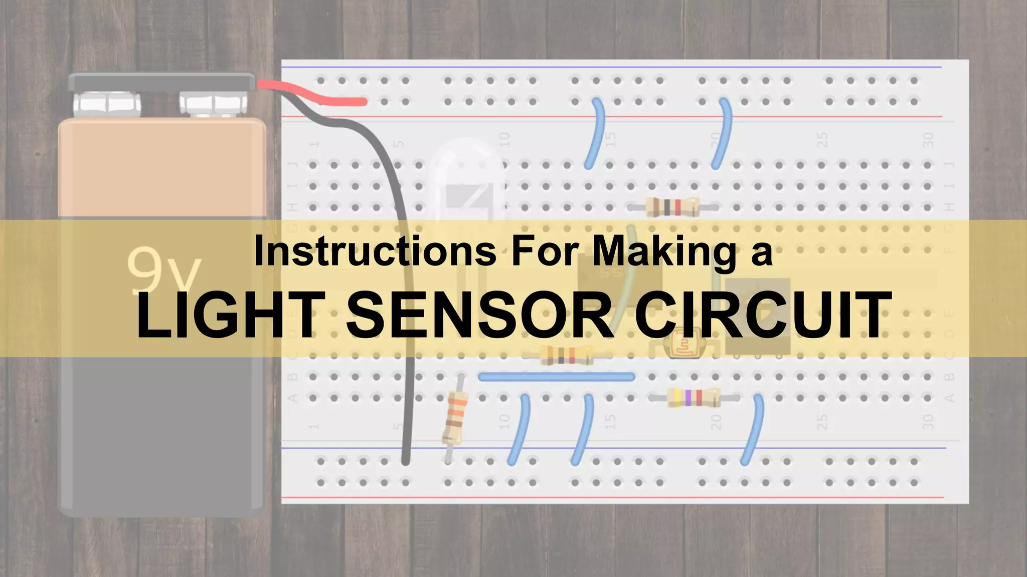
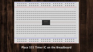
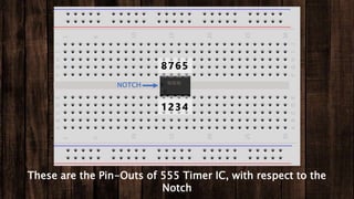
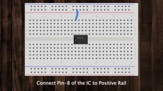
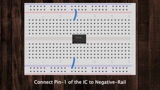
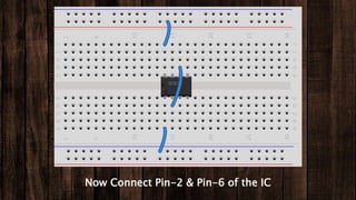
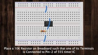
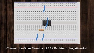
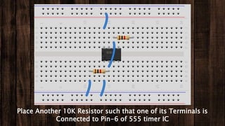
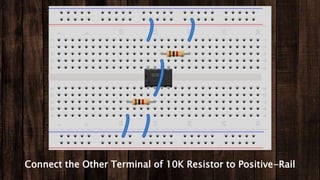
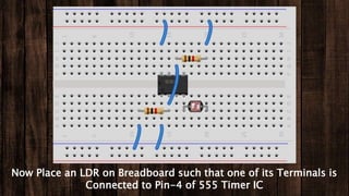
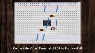
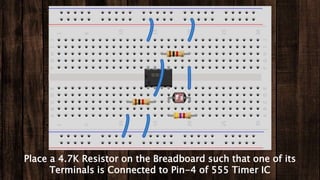
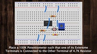
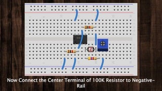
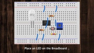
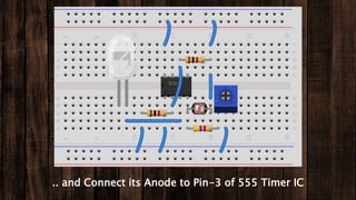
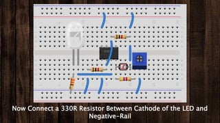
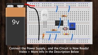
Instructions For Making a
LIGHT SENSOR CIRCUIT
Place 555 Timer IC on the Breadboard
These are the Pin-Outs of 555 Timer IC, with respect to the
Notch
1234
8765
NOTCH
Connect Pin-8 of the IC to Positive Rail
Connect Pin-1 of the IC to Negative-Rail
Now Connect Pin-2 & Pin-6 of the IC
Place a 10K Resistor on Breadoard such that one of its Terminals
is Connected to Pin-2 of 555 timer IC
Connect the Other Terminal of 10K Resistor to Negative-Rail
Place Another 10K Resistor such that one of its Terminals is
Connected to Pin-6 of 555 timer IC
Connect the Other Terminal of 10K Resistor to Positive-Rail
Now Place an LDR on Breadboard such that one of its Terminals is
Connected to Pin-4 of 555 Timer IC
Connect the Other Terminal of LDR to Positive-Rail
Place a 4.7K Resistor on the Breadboard such that one of its
Terminals is Connected to Pin-4 of 555 Timer IC
Place a 100K Potentiometer such that one of its Extereme
Terminals is Connected to the Other Terminal of 4.7K Resistor
Now Connect the Center Terminal of 100K Resistor to Negative-
Rail
Place an LED on the Breadboard ..
.. and Connect its Anode to Pin-3 of 555 Timer IC
Now Connect a 330R Resistor Between Cathode of the LED and
Negative-Rail
Connect the Power Supply.. and the Circuit is Now Ready!
Video + More Info in the Description Below

How to Make a Light Sensor Circuit with Adjustable Sensitivity