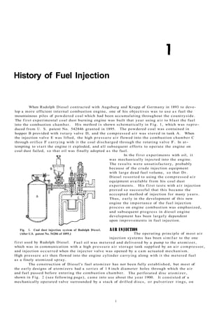
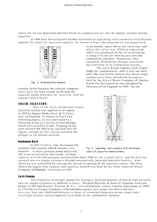
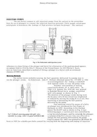
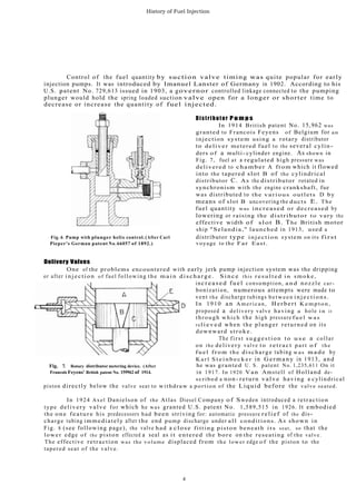
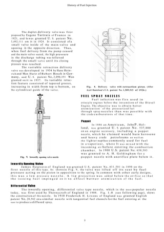
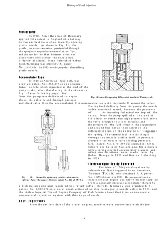
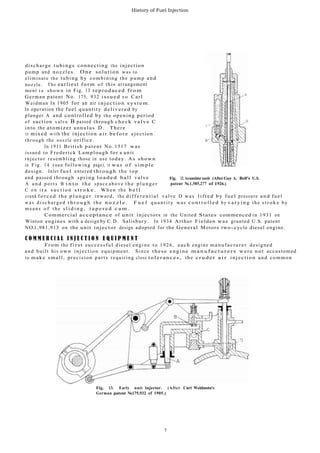
Rudolph Diesel originally experimented with injecting powdered coal into his engine using compressed air, which failed. He then switched to injecting oil using compressed air, which was successful. Early fuel injection systems used compressed air to atomize the fuel. Over time, mechanical injection pumps were developed to pressurize the fuel. Early nozzles had multiple holes but single-hole swirl nozzles became popular. Delivery valves were improved to prevent dripping after injection. Common components of modern injection systems, like distributor pumps and inwardly opening nozzles, were introduced in the early 20th century. Developments in injection pumps, delivery valves, and nozzles improved atomization and engine performance.
2. History of Fuel Injection
When Rudolph Diesel contracted with Augsburg and Krupp of Germany in 1893 to deve-
lop a more efficient internal combustion engine, one of his objectives was to use a s fuel the
mountainous piles of powdered coal which had been accumulating throughout the countryside.
The first experimental coal dust burning engine was built that year using a i r to blast the fuel
into the combustion chamber. His method i s shown schematically in Fig. 1, which was repro-
duced from U. S. patent No. 542846 granted in 1895. The powdered coal was contained in
hopper B provided with rotary valve D, and the compressed a i r was stored in tank A. When
the injection valve E was lifted, the high p r e s s u r e a i r flowed into the combustion chamber C
through orifice F carrying with it the coal discharged through the rotating valve F. In at-
tempting to s t a r t the engine it exploded, and all subsequent efforts to operate the engine on
coal dust failed, s o that oil was finally adopted a s the fuel.
In the f i r s t experiments with oil, it
was mechanically injected into the engine.
The results were unsatisfactory, probably
because of the crude injection equipment
with large dead fuel volume, s o that Dr.
Diesel resorted to using the compressed a i r
equipment available from his coal dust
experiments. His f i r s t tests with a i r injection
proved s o successful that this became the
acccepted method of injection for many y e a r s .
Thus, early in the development of this new
engine the importance of the fuel injection
process on engine combustion was emphasized,
and subsequent progress in diesel engine
development has been largely dependent
upon improvements in fuel injection.
Fig. 1. Coal dust injection system of Rudolph Diesel. A I R INJ ECTION
(After U.S. patent No. 54286 of 1895.) The operating principle of most a i r
injection systems has been similar to the one
first used by Rudolph Diesel. Fuel oil was metered and delivered by a pump to the atomizer,
which was in communication with a high p r e s s u r e a i r storage tank supplied by an a i r compressor,
and injection occurred when the injector valve was opened by a cam actuated mechanism.
High pressure a i r then flowed into the engine cylinder carrying along with it the metered fuel
as a finely atomized spray.
The construction of Diesel's fuel atomizer has not been fully established, but most of
the early designs of atomizers had a s e r i e s of 1 8 inch diameter holes through which the a i r
and fuel passed before entering the combustion chamber. The perforated disc atomizer,
shown in Fig. 2 (see following page), came into use about the year 1900. It consisted of a
mechanically operated valve surrounded by a stack of drilled discs, o r pulverizer rings, on
1
3. History of Fuel Injection
w h i c h t h e oil was deposited and t h e n blown by compressed air into the engine c y l i n d e r during
injection.
In 1908 Knut H e s s e l m a n of Sweden disclosed an aspirating valve atomizer wich became
popular f o r s m a l l a i r i n j e c t i o n e n g i n e s . As shown in Fig.3, the metered o i l w a s d e p o s i t e d
Fig. 2. Perforated disc atomizer.
scheme failed because the exhaust tempera-
t u r e s w e r e not high enough to develop the
required steam pressure f o r i n j e c t i o n with the
exhaust heated boiler.
S O L I D I N J E C T I O N
O n e o f t h e f i r s t satisfactory airless
injection system was applied to an engine
i n 1910 b y James M c K e c h n i e of Vickers,
Ltd. of England. As shown in Fig.4 (see
following page), oil was delivered by a
metering pump to a s p r i n g l o a d e d plunger,
which was raised by a cam. Tripping of the
cam allowed the fuel to be injected into the
engine cylinder as t h e s p r i n g returned the
plunger to its bottom position.
Common R a i l
in an annular space above the valve seat, and
w h e n t h e v a l v e w a s lifted an aspirating
effect w a s produced on the oil to discharge
i t along w i t h the air flowing p a s t into the
combustion chamber. Numerous o t h e r
variations of atomizer designs were tried,
but with little or no commercial success.
The e a r l y Krupp engines used single-
stage air compressors, and it was not until
after the turn of t h e century t h a t three-stage
c o m p r e s s o r s were introduced on engines
built by the D i e s e l Motor Company of America.
Steam for fuel injection was attempted by
Thornycroft of England in 1903, but the
In 1913 Vickers, Ltd. developed the
common rail system which became v e r y Fig. 3. Aspirating valve atomizer of K. Hesselman.
popular . A multi- plunger pump delivered (After U.S. patent No. 910534 of 1909.)
fuel to an a c c u m u l a t o r and h e a d e r of l a r g e
c a p a c i t y w i t h the fuel pressure maintained at about 5000 p s i by a relief valve, and the fuel was
s p r a y e d into t h e engine cylinders through mechanically operated injection nozzles. Fuel
metering was controlled by varying the period of opening of the injection valves. The first
American engine with common rail injection s y s t e m was built by t h e Atlas Imperial Diesel
Company of Oakland, California in 1919.
J e r k Pumps
T h e originator of plunger pumps for forcing a metered quantity of fuel at high p r e s s u r e
into t h e engine cylinders is difficult t o trace. Richard Hornsby & Sons of England used jerk
pumps in 1891 and Ruston, Proctor & C o . , a l s o of England, used a similar type pump in 1909.
In 1914 De La Vergne Company of Philadelphia used a j e r k p u m p that delivered fuel
at a v e r y high rate (full load delivery i n a b o u t 1 2 c r a n k s h a f t degrees) to two single hole,
s w i r l t y p e nozzles located opposite e a c h o t h e r in t h e combustion chamber.
2
4. History of Fuel Injection
I N J E C T I O N P U M P S
The one feature common to a l l injection pumps from the earliest to the present has
been the use of plungers to c r e a t e the required injection pressure. Early pumps relied upon
packed glands to m i n i m i z e the leakage of high pressure fuel past the plunger. The e a r l i e s t
Fig. 4. The McKechnie solid injection system
reference to close fitting of the plunger and barrel for elimination of the packing gland appears
in a patent filed in 1912 by Otto F. Persson of the United States. In 1919 Philip L. Scott,
also an American, described a method of fitting a plunger to a barrel with an estimated
clearance of 0.0001 inch.
Metering Methods
The earliest known methodfor varying the fuel quantity delivered by a pump was to
vary the plunger stroke. An American, John F. Holland, obtained patent No. 337,000 in 1886
on an arrangement for sliding a camshaft
with tapered cams to vary the pump stroke.
Another early method of metering
control was by means of a spill valve. In
1900 U.S. patent No. 654,140 was granted
to Rudolph Diesel for a wedge controlled
spill valve pump as shown in Fig. 5.
The duration of the plunger stroke during wich
the by-pass valve D was closed was lenghtened
or reduced by moving the wedge K in or out, thus
increasing or decreasing the fuel quantity
delivered by the pump.
Fuel metering control by means of a helix
on plunger was introduced by Carl Pieper of
Germany in 1892. According to his German
patent No.66,057 and as shown in Fig. 6 (see
following page), a suction port was controlled by
Fig. 5. R .Diesel's metering pump with spill valve a top beveled plunger, and by rotating the plunger
controlled by a wedge. (After U.S. patent No.654140 of 1900) a variation of the Port closure time was effected to
change the fuel quantity delivered by the pump.
English patent No. 9403 was granted to William H.
Scott in 1895 for a double port helix control for varying both the beginning and ending of injection.
3
5. History of Fuel Injection
Control of the fuel quantity by suction valve timing was quite popular for early
injection pumps. It was introduced by Imanuel Lanster of Germany in 1902. According to his
U.S. .patent No. 729,613 issued in 1903, a governor controlled linkage connected to the pumping
plunger would hold the spring loaded suction valve open for a longer or shorter time to
decrease or increase the quantity of fuel injected.
Distributor P u m p s
In 1914 British patent No. 15,962 was
granted to Francois Feyens of Belgium for an
injection system using a rotary distributor
to deliver metered fuel to the several cylin-
ders of a multi-cylinder engine. As shown in
Fig. 7, fuel at a regulated high pressure was
delivered to chamber A from which it flowed
into the tapered slot B of the cylindrical
distributor C. As the distributor rotated in
synchronism with the engine crankshaft, fue
was distributed to the various outlets D by
means of slot B uncovering the ducts E. The
fuel quantity was increased or decreased by
lowering or raising the distributor to vary the
effective width of slot B. The British motor
ship "Selandia," launched in 1913, used a
Fig. 6. Pump with plunger helix control. (After Carl distributor type injection system on its first
Pieper's German patent No. 66057 of 1892.) voyage to the Far East.
Delivery Valves
One of the problems encountered with early jerk pump injection system was the dripping
or after injection of fuel following the m a i n discharge. S i n c e this r e s u l t e d i n smoke,
increased fuel consumption, a n d nozzle car-
bonization, numerous attempts were made to
vent the discharge tubings between injections.
In 1910 an American, Herbert K e m p t o n ,
proposed a delivery valve having a hole i n it
through which the high pressure f u e l w a s
rel i e v e d when the plunger returned on its
downward stroke.
The first suggestion t o u s e a collar
on the delivery valve to r e t r a c t part o f the
f u e l f r o m the discharge tubing was m a d e by
K a r l S t e i n b e c k e r in Germany in 1913, and
Fig. 7. Rotary distributor metering device. (After he was granted U. S. patent No. 1,235,611 On it
Francois Feyens' British patent No. 159962 of 1914. in 1917. In 1920 Van Amstell of Holland de-
scribed a non- return valve having a cylindrical
piston directly below the valve seat to withdraw a portion of the Liquid before the valve seated.
In 1924 Axel Danielson of the Atlas Diesel Company of Sweden introduced a retraction
type delivery valve for which he was granted U.S. patent No. 1,589,515 in 1926. It embodied
the one feature his predecessors had been striving for: automatic pressure relief of the dis-
charge tubing immediately after the end pump discharge under all conditions. As shown in
Fig. 8 (see following page), the valve had a close fitting piston beneath its seat, so that the
lower edge of the piston effected a seal as it entered the bore on the reseating of the valve.
The effective retraction was the volume displaced from the lower edge of the piston to the
tapered seat of the valve.
4
6. History of Fuel Injection
The duplex delivery valve was first
proposed by Eugene Tartrais of France in
1921, and he was granted U. S. patent No.
1,492,111 on it in 1924. It consisted of a
small valve inside of the main valve and
opening in the opposite direction. Thus,
when fuel delivery from the pump ceased
and the main valve seated, the high pressure
in the discharge tubing was relieved
through the small valve until its closing
pressure was reached.
The variable retraction delivery
valve was developed in 1934 by Hans Hein-
rich and Max Hurst of Robert Bosch in Ger-
many, and U. S. patent No, 2,090,351 Was
granted on it in 1937. Its variable retrac-
tion feature consisted of tapered grooves,
increasing in width from top to bottom, on Fig. 8. Delivery valve with retraction piston. (After
the cylindrical guide of the valve. Axel Danielson's U.S. patent No. 1,589,515 of 1926.)
Fig. 9. Inwardly opening valve nozzle
F U E L S P R A Y N O Z Z L E S
F u e l i n f e c t i o n w a s f i r s u s e d i n
o t t o c y l e engines before t h e i n v e n t i o n o f t h e D i e s e l
E n g i n e . T h e objective was t o o b t a i n b e t t e r
a t o m i z a t i o n o f t h e p r e s s u r i z e d f u e l
t h r o u g h s p r a y n o z z l e s t h a n w a s p o s s i b l e w i t h
t h e crude c a r b u r e t o r s o f t h a t t i m e .
Poppet
I n 1 8 8 6 a n A m e r i c a n , John P . H o l -
l a n d , w a s g r a n t e d U . S. p a t e n t N o . 537,000
on a n e n g i n e accessory, i n c l u d i n g a p o p p e t
nozzle, w h i c h h e c l a i m e d w o u l d b u r n k e r o s e n e
a n d h e a v y crude p e t r o l e u m s a s w e l l a s
t h e l i g h t e r napthas c o m m o n l y u s e d f o r f u e l
i n a v a p o r i z e r , w h e r e I t w a s m i x e d w i t h t h e
i n c o m i n g a i r b e f o r e e n t e r i n g t h e c o m b u s t i o n
c h a m b e r . In 1900 U.S. patent No. 650,583
w a s g r a n t e d t o A . H . G o l d i n g h a m f o r a
p o p p e t n o z z l e w i t h a n o r i f i c e p l a t e b e l o w i t .
Inwardly Opening Valve
J a m e s Hargreaves of E n g l a n d was g r a n t e d U . S, p a t e n t N o , 4 3 1 . 5 8 1 i n 1 8 9 0 o n t h e
f i r s t n o z z l e of this type. As showni n F i g . 9 , the v a l v e was l i f t e d o f f i t s s e a t b y f u e l
pressure acting on the piston in opposition to the spring. In common with other early designs,
t h i s w a s a l o w p r e s s u r e n o z z l e . A l i p p r o j e c t i o n w a s a d d e d b e l o w t h e o r i f i c e s o t h a t
t h e i s s u i n g f u e l i m p i n g e d o n i t t o e f f e c t b e t t e r a t o m i z a t i o n o f t h e f u e l .
Differential Valve
The inwardly opening, differential valve type nozzle, which i s the most popular nozzle
today, was first used by Thornycroft of England in 1908. Fig. 1 . 0 (see following page), shows
the construction of this nozzle. In 1910 Frederick H. Livens of England was granted English
patent No, 20,582 on a similar nozzle with tangential fuel channels for the fuel entering at the
seat to produce a diffused spray.
5
7. History of Fuel Injection
Pintle Valve
In 1910, Peter Bowman of Denmark
applied for a patent in England on what may
be the earliest form of a n inwardly opening,
pintle nozzle. As shown in Fig. 11, the
pintle, or valve extension, protruded through
the spray hole to produce an annular orifice,
and the seat for the f l a t bottom valve was
close to the orifice so that the nozzle had
differential action. Hans Heinrich of Robert
Basch, Germany was granted U.S. patent
No. 2,017,028 in 1935 on the popular throttling
pintle nozzle.
Accumulator Type
In 1 9 2 6 an A m e r i c a n , G u y B e l l , was
g r a n t e d p a t e n t N o .1,585,277 on a n a c c u m u -
l a t o r n o z z l e w h i c h i n j e c t e d at t h e e n d o f t h e
p u m p stroke, r a t h e r t h a n d u r i n g i t . A s s h o w n i n
F i g . 1 2 (see f o l l o w i n g p a g e ) , f u e l
f r o m t h e p u m p was d e l i v e r e d t o a space Fig. 10 Inwardly opening differential nozzle of Thornycroft
a b o v e the v a l v e A a n d t h r o u g h passages
and check valve B to the accumulator C in communication with the chamber D around the valve.
D u r i n g f u e l d e l i v e r y f r o m the p u m p t h e n o z z l e
v a l v e r e m a i n e d seated, b e c a u s e the p r e s s u r e
o f the incoming fuel a c t e d o n t o p o f the
v a l v e . W h e n t h e p u m p s p i l l e d a t t h e e n d o f
i t s e f f e c t i v e s t r o k e t h e high pressure f u e l a b o v e
the v a l v e d r o p p e d t o a l o w pressure, and
the pressure of the fuel stored in the accumulator
and a r o u n d t h e v a l v e t h e n a c t e d o n t h e
d i f f e r e n t i a l a r e a o f t h e v a l v e to lift it against
the s p r i n g . T h e s t o r e d f u e l t h e n d i s c h a r g e d
t h r o u g h t h e n o z z l e o r i f i c e u n t i l i t s p r e s s u r e
dropped t o the n o z z l e valve c l o s i n g p r e s s u r e .
U . S . p a t e n t N o . 1,701,089 was granted in 1929 to
Edward Von Salis o f S w i t z e r l a n d f o r a n o z z l e
w i t h a s p r i n g o p e r t e d a c c u m u l a t o r p l u n g e r , a n d
o t h e r m o d i f i c a t i o n s w e r e m a d e l a t e r b y
R o b e r t B r o e g e i n 1 9 3 1 a n d G u s t a v E i c h e l b e r g
i n 1 9 3 9 .
. E l e c t r o -m a g n e t i c a l l y O p e r a t e d
T h e i d e a of lifting n o z z l e v a l v e s b y
solenoids was f i r s t suggested by a n A m e r i c a n ,
T h o m a s T .G a f f , w h o o b t a i n e d U.S. patent
Fig. 11. Inwardly opening pintle valve nozzle. No. 1,059,604 on it in 1913. He proposed such a
(after Petcr Bowman's British patent No. 146 of 1910.) nozzle f o r each engine c y l i n d e r w i t h f u e l s u p p l i e d
f r o m a c o n s t a n t p r e s s u r e a c c u m u l a t o r c h a r g e d b y
a high pressure p u m p a n d r e g u l a t e d b y a r e l i e f v a l v e . Harry E . K e n n e d y w a s g r a n t e d U . S .
p a t e n t N o . 1,092,956 on a n o v e l c o n s t r u c t i o n o f a n e l e c t r o - m a g n e t i c n o z z l e v a l v e i n 1 9 3 3 , a n d
t h e A t l a s - I m p e r i a l D i e s e l E n g i n e C o m p a n y o f C a l i f o r n i a a b o u t t h a t t i m e a n n o u n c e d a
c o m m e r c i a l i n j e c t i o n s y s t e m w i t h t h i s t y p e of noz z le .
U N I T I N J E C T O R S
From the earliest days of the diesel engine, troubles were encountered with the fuel
6
8. History of Fuel Injection
discharge tubings connecting the injection
pump and nozzles. One solution was to
eliminate the tubing by combining the pump and
nozzle. The earliest form of this arrangement
ment i s shown in Fig. 13 reproduced from
German patent No. 175, 932 issued t o Carl
Weidman In 1905 for an air injection s y s t e m .
In operation the fuel quantity delivered by
plunger A and controlled by the opening period
of suction valve B passed through check valve C
into the atomizer annulus D. There
it mixed with the injection air before ejection
through the nozzle orifice.
In 1911 British patent No. 1517 was
issued to Frederick Lamplough for a unit
injector resembling those in use today. As shown
in Fig. 14 (see following page), it was of simple
design. Inlet fuel entered through the top
and passed through spring loaded ball valve Fig. 12. Accumulator nozzle (AfterGuy A. Bell's U.S.
A a n d p o r t s B i n t o t h e space a b o v e t h e p l u n g e r patent No.1,585,277 of 1926.)
C o n i t s s u c t i o n s t r o k e . W h e n the b e l l
crank forced the p l u n g e r inward, the d i f f e r e n t i a l valve D w a s lifted by fuel pressure and fuel
w a s d i s c h a r g e d t h r o u g h t h e n o z z l e . F u e l q u a n t i t y was c o n t r o l l e d b y v a r y i n g t h e s t r o k e b y
means o f t h e s l i d i n g , t a p e r e d c a m .
Commercial acceptance of unit injectors in the United States commenced in 1931 on
Winton engines with a design by C.D. Salisbury. In 1934 Arthur Fielden was granted U.S. patent
NO.1,981,913 on the unit injector design adopted for the General Motors two-cycle diesel engine.
C O M M E R C l A L I N J E C T I O N E Q U I P M E N T
From the first successful diesel engine to 1926, each engine manufacturer designed
and built his own injection equipment. Since these engine m a n u f a c t u r e r s were not accustomed
to make small, precision parts requiring close tolerances, the cruder a i r injection and common
Fig. 13. Early unit injector. (After Cnrl Weidmstn's
German patent No.175,932 of 1905.)
7
9. History of Fuel Injection
r a i l f u e l i n j e c t i o n s y s t e m s w e r e u s e d
e x c l u s i v e l y o n t h e r a t h e r l a r g e e n g i n e s o f t h a t A
p e r i o d . S m a l l e n g i n e s , e s p e c i a l l y o f t h e
a u tomotive type, were not particularly successful,
primarily because o f the lack o f s u i t a b l e f u e l
injection e q u i p m e n t .
I n D e c e m b e r , 1922 the R obe r t B o s c h
C o m p a n y of S t u t t g a r t , G e r m a n y decided t o
manufacture f u e l i n j e c t i o n equipment, and after
years o f d e v e l o p m e n t i t s p o p u l a r jerk
p u m p w i t h h e l i x control, for w h i c h U . S .
patent No. 1 , 8 3 1 , 6 4 9 was granted to O t t m a r
Bauer i n 1 9 3 1 , was introduced i n 1 9 2 7 in both
single and mu ltip le plunger types. About the
same time p r e c i s i o n n o z z l e assemblies o f
t h e p i n t l e a n d h o l e t y p e were introduced, and
s u b s e q u e n t l y o t h e r i t e m s s u c h a s s u p p l y
p u m p s , g o v e r n o r s , a n d f i l t e r s w e r e m a r k e t e d . Fig. 14. Unit injector with differential nozzle valve.
W i t h t h e a v a i l a b i l i t y o f t h i s i n j e c t i o n (After Frederick Lamplough's British patent No. 1,517
e q u i p m e n t t h e h i g h s p e e d d i e s e l e n g i n e c a m e of 1911.)
i n t o e x i s t e n c e . I n a r e l a t i v e l y s h o r t t i m e
other companies started manufacturing standardized types of fuel injection equipment for all
types of engines and progress in diesel engine development swung into high gear.
8