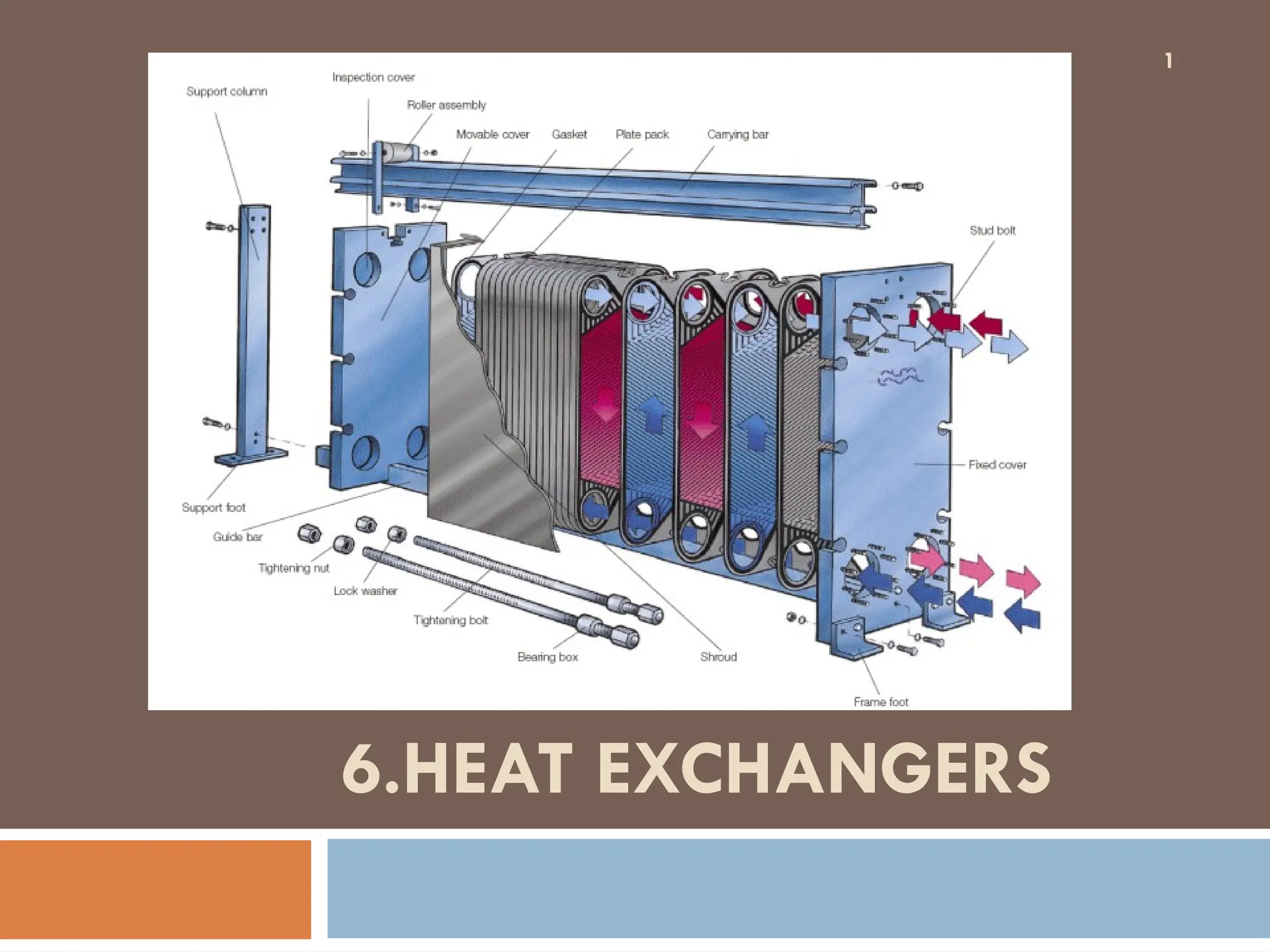
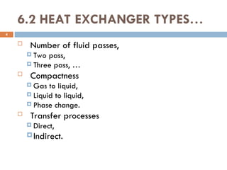
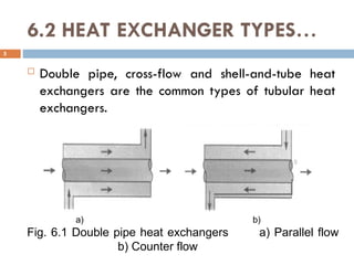
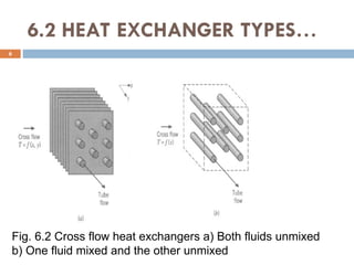
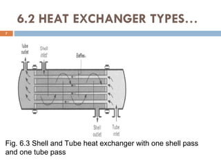
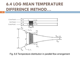
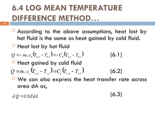
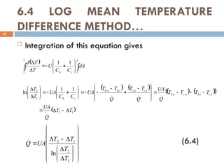
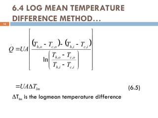
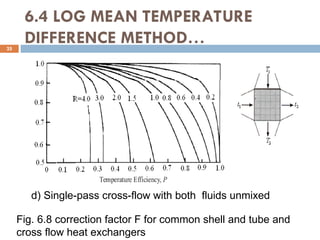
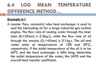
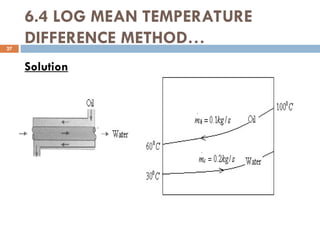
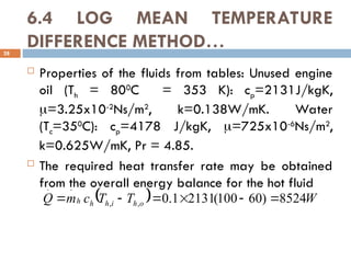
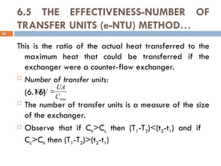
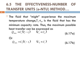
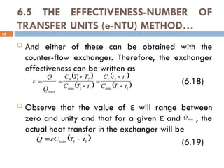
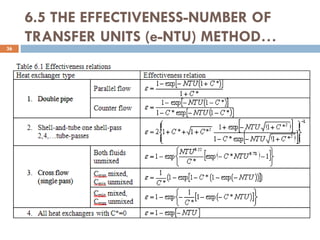
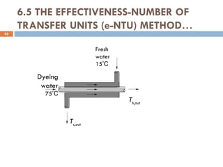
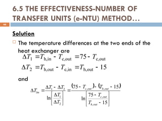
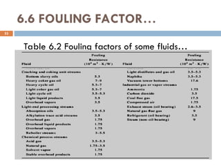
The document provides an overview of heat exchangers, defining them as devices that transfer heat between fluids at different temperatures and detailing their various applications such as in heating and cooling, power production, and chemical processing. It categorizes heat exchangers by flow arrangement, construction type, and transfer processes, while also discussing analysis techniques like the log mean temperature difference (LMTD) and effectiveness-number of transfer units (ε-NTU) methods. Furthermore, it illustrates the equations used for calculating heat transfer rates and temperatures for different types of heat exchangers.


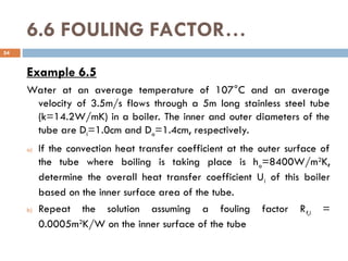
![6.6 FOULING FACTOR…
57
C/W
00157
.
0
=
]
m)
m)(5
(0.014
C)[
.
W/m
8400
(
1
m)]
C)(5
W/m.
2
.
14
(
2
[
)
1
/
4
.
1
ln(
]
m)
m)(5
(0.01
C)[
.
W/m
324
,
23
(
1
1
2
)
/
ln(
1
2
2
o
o
i
o
i
i
o
wall
i
total
A
h
kL
D
D
A
h
R
R
R
R
R
and
C
.
W/m
4055 2
]
m)
m)(5
(0.01
C/W)[
00157
.
0
(
1
1
1
i
i
i
i RA
U
A
U
R](https://image.slidesharecdn.com/chapter6-241210145110-5b208bbd/85/Heat-transfer-Heat-exchanger-Chapter6-ppt-57-320.jpg)
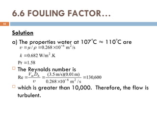
![6.6 FOULING FACTOR…
b) The thermal resistance of heat exchanger with a
fouling factor of Rf,i=0.0005m2
.0
C/W is
determined from
58
C/W
00476
.
0
m)]
m)(5
014
.
0
(
[
C)
.
W/m
8400
(
1
m)
C)(5
W/m.
2
.
14
(
2
)
1
/
4
.
1
ln(
m)]
m)(5
01
.
0
(
[
C/W
.
m
0005
.
0
m)]
m)(5
01
.
0
(
[
C)
.
W/m
324
,
23
(
1
1
2
)
/
ln(
1
2
2
2
,
R
A
h
kL
D
D
A
R
A
h
R
o
o
i
o
i
i
f
i
i](https://image.slidesharecdn.com/chapter6-241210145110-5b208bbd/85/Heat-transfer-Heat-exchanger-Chapter6-ppt-58-320.jpg)
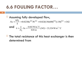
![6.6 FOULING FACTOR…
Then,
59
C
.
W/m
1337 2
]
m)
m)(5
(0.01
C/W)[
00476
.
0
(
1
1
1
i
i
i
i RA
U
A
U
R](https://image.slidesharecdn.com/chapter6-241210145110-5b208bbd/85/Heat-transfer-Heat-exchanger-Chapter6-ppt-59-320.jpg)