This document provides specifications for installing high-density polyethylene (HDPE) sealing sheets. It outlines material requirements, testing procedures, installation instructions, welding requirements, and repair protocols. The HDPE sheets must meet certain physical property values and be tested during manufacture. Installation involves preparing the surface, unrolling panels to minimize wrinkles, inspecting panels for defects, and securing edges. Welds between panels are tested and must meet strength standards. Any repairs to the liner follow defined evaluation and repair procedures. Special considerations are given for installing liners in tropical environments.
I recently retrieved this presentation on extrusion coating and lamination from more than 20 years ago.
Until 1998 BASF was organizing a film seminar combining classroom and practical training. I was working as a film service technician and application developer at Fos-sur-Mer, a former Shell site in southern France, where two high-pressure autoclave reactors were producing mainly extrusion coating and special blown film LDPE grades. I was at the time also the company's global extrusion coating expert when BASF and SHELL had decided to divest their polyethylene activities in a common subsidiary they branded ELENAC (that later merged with TARGOR to become Basell, which itself later acquired Lyondell to give birth to Lyondellbasell) until it was decided to exit from extrusion coating activities and sometime later to shut down the production of LDPE with autoclave reactors that had become uneconomical to operate. This presentation represents the apex of one year on my implication in extrusion coating and the first and last time I had the opportunity to present it during the last film seminar session ever taking place for german customers. After that the seminar was cancelled and never had I a chance to make an english version. The slides are mostly self-explaining and little has changed as well on the fundamental concepts of extrusion-coating and extrusion-lamination.
A release liner is a critical element in a pressure sensitive adhesive product - perhaps as important as the adhesive itself. Pressure sensitive tapes, labels, and transfer films must be protected from accidental contact with other surfaces. They must also be constructed to allow for winding into rolls for the
purpose of packaging and application. Without a release liner many PSA products could not be produced and the end user would be faced with an unworkable lump of sticky adhesive.
This presentation Based on Non Destructive Testing.the Abbreviation is NDT.Dye penetrant Testing (DPT) is the part of NDT .I think my presentation will be helpful for NDT Related person
Introduction to Techsil's Hotmelt Adhesive and Glue Gun RangeTechsil Ltd
An introduction to Techsil's range of different Hotmelt adhesives and glue guns and their applications in manufacturing sectors. Contains a useful selection guide.
Introduction to waterborne paints & coatings rheologyspecialchem-ada
To get additional information, you can use the following link: goo.gl/dxR59V
In this presentation, the technical expert explains how Rheology influences in-can properties, paint texture, application properties & film properties.
You will find some product recommendations: the right dispersants and thickeners (Acrylic, HEUR) to be used in various formulation types to improve coating properties.
If you would like to get more detailed information on Rheology, click on the following link: goo.gl/dxR59V
This is an introductory presentation into the world of linings that are used in various industries. We will review what a lining is and what types of linings exist in the market place. We will also discuss how to choose or specify a lining system which includes surface preparation, proper application, repairs to lining defect and how fast a lining will be ready for service.
If you have any questions Contact us at:
http://info.international-pc.com/Solutions
General Specification for Thermofoil Heater, All-Polyimide, Space ApplicationsBelilove Company-Engineers
Purpose. This specification establishes the requirements for thermofoil heaters of an all- polyimide (adhesive-less) construction for high reliability space applications. It defines the process, test verification, and inspections required by product used in space flight applications.
Water scarcity is the lack of fresh water resources to meet the standard water demand. There are two type of water scarcity. One is physical. The other is economic water scarcity.
Industrial Training at Shahjalal Fertilizer Company Limited (SFCL)MdTanvirMahtab2
This presentation is about the working procedure of Shahjalal Fertilizer Company Limited (SFCL). A Govt. owned Company of Bangladesh Chemical Industries Corporation under Ministry of Industries.
Hierarchical Digital Twin of a Naval Power SystemKerry Sado
A hierarchical digital twin of a Naval DC power system has been developed and experimentally verified. Similar to other state-of-the-art digital twins, this technology creates a digital replica of the physical system executed in real-time or faster, which can modify hardware controls. However, its advantage stems from distributing computational efforts by utilizing a hierarchical structure composed of lower-level digital twin blocks and a higher-level system digital twin. Each digital twin block is associated with a physical subsystem of the hardware and communicates with a singular system digital twin, which creates a system-level response. By extracting information from each level of the hierarchy, power system controls of the hardware were reconfigured autonomously. This hierarchical digital twin development offers several advantages over other digital twins, particularly in the field of naval power systems. The hierarchical structure allows for greater computational efficiency and scalability while the ability to autonomously reconfigure hardware controls offers increased flexibility and responsiveness. The hierarchical decomposition and models utilized were well aligned with the physical twin, as indicated by the maximum deviations between the developed digital twin hierarchy and the hardware.
Cosmetic shop management system project report.pdfKamal Acharya
Buying new cosmetic products is difficult. It can even be scary for those who have sensitive skin and are prone to skin trouble. The information needed to alleviate this problem is on the back of each product, but it's thought to interpret those ingredient lists unless you have a background in chemistry.
Instead of buying and hoping for the best, we can use data science to help us predict which products may be good fits for us. It includes various function programs to do the above mentioned tasks.
Data file handling has been effectively used in the program.
The automated cosmetic shop management system should deal with the automation of general workflow and administration process of the shop. The main processes of the system focus on customer's request where the system is able to search the most appropriate products and deliver it to the customers. It should help the employees to quickly identify the list of cosmetic product that have reached the minimum quantity and also keep a track of expired date for each cosmetic product. It should help the employees to find the rack number in which the product is placed.It is also Faster and more efficient way.
Overview of the fundamental roles in Hydropower generation and the components involved in wider Electrical Engineering.
This paper presents the design and construction of hydroelectric dams from the hydrologist’s survey of the valley before construction, all aspects and involved disciplines, fluid dynamics, structural engineering, generation and mains frequency regulation to the very transmission of power through the network in the United Kingdom.
Author: Robbie Edward Sayers
Collaborators and co editors: Charlie Sims and Connor Healey.
(C) 2024 Robbie E. Sayers
Welcome to WIPAC Monthly the magazine brought to you by the LinkedIn Group Water Industry Process Automation & Control.
In this month's edition, along with this month's industry news to celebrate the 13 years since the group was created we have articles including
A case study of the used of Advanced Process Control at the Wastewater Treatment works at Lleida in Spain
A look back on an article on smart wastewater networks in order to see how the industry has measured up in the interim around the adoption of Digital Transformation in the Water Industry.
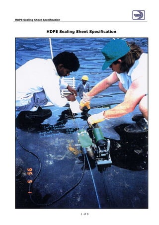
2. HDPE Sealing Sheet Specification
of 92
Table of Contents
1. GENERAL 3
2. PRODUCTS 3
2.1 GENERAL REQUIREMENTS 3
2.2 HDPE LINER 3
2.2.1.1 SMOOTH HDPE LINER 3
2.2.2 TESTS ON HDPE DURING MANUFACTURE 4
2.2.3 LINER MATERIAL & MANUFACTURES WARANTY 4
2.2.4 THIRD PARTY TESTING 5
2.2.5 DELIVERY, STORAGE AND HANDLING 5
3. EXECUTION 5
3.1 INSTALLATION PROCEDURE FOR THE LINER 5
3.1.1 GENERAL 5
3.1.2 PREPERATION FOR THE INSTALLATION 5
3.1.3 LINER INSTALLATION 5
3.1.4 PANEL PLACEMENT 6
3.1.5 PANEL INSPECTION 6
3.1.6 WEATHER CONDITIONS 6
3.1.6.1 TEMPERATURE 6
3.1.6.2 HUMIDITY 6
4.0 WELDING OF SEAMS 6
4.1 GENERAL 6
4.1.1 SEAM WELDING 6
4.2 MINIMUM REQUIREMENTS FOR INSPECTION & TESTING 7
4.2.1 NON DESSTRUCTIVED TESTING 7
4.2.2 DESTRUCTIVE TESTING FIELD SEAMS SHALL MEET THE FOLLOWING SPECIFICATIONS 8
5. REPAIRS AND DEFECTS 8
5.1 GENERAL 8
5.2 EVALUATION 8
5.3 REPAIR PROCEDURES 8
5.4 RESTART / RESEAMING PROCEDURES 8
5.5 VERTIFICATION OF REPAIRS 8
5.6 RECORDING OF RESULTS 9
6. SPECIAL INSTRUCTIONS FOR INSTALLING IN TROPICAL ENVIRONMENTS 9
6.1 MATERIAL DEPLOYMENT 9
6.2 DUST AND SAND 9
6.3 HIGH AMBIENT TEMPERATURE 9
6.4 HUMIDITY 9
3. HDPE Sealing Sheet Specification
of 93
1. GENERAL
The following information about HDPE liner and description of material handling and
welding shall give an overview only, these information are not exhaustive and does not lay
claim to completeness.
1.1 Work included
1.1.1 Comply General Requirements and all documents referred to therein.
1.1.2 Provide all laborers, materials, products, equipment and services to supply and
install the HDPE liner as required therein.
1.2 Reference Standard
1.2.1 Only products, which have been successfully used in the climate similar to that
expected for this project. The material must be compatible with the chemicals used
in this application. Use only HDPE material with a Melt Flow Index (MFI 190/5) of
more than 2.00 g/10min, but less than 3.00 g/10min, using test method DIN EN
ISO 1133.
1.2.2 Only a field technician having the educational and practical background in the field
of HDPE lining shall supervise the laying and perform the welding work.
2. PRODUCTS
2.1 General Requirements
2.1.1 Approved liner manufactures and their representative is Naue Fasertechnik (Germany),
Carbofol®
406 HDPE membrane.
2.1.2 Guarantee from liner manufacturer shall be given.
2.2 HDPE Liner
2.2.1 Material Specification
The lining material shall be of highest quality high density polyethylene (HDPE) sheeting,
manufactured in a flat sheet extrusion process using virgin high density polyethylene resin
entirely free of plasticisers or other filler materials, according to a recognized standard.
The liner material shall be compatible with chemicals to be contained on site.
2.2.1.1 Smooth HDPE liner
The liners shall be of such dimensions and shape as will result in controllable installation
with minimum wrinkles and stress in the HDPE liner. The smooth HDPE liner shall meet the
following physical property values. The values in the table on next page are minimum roll
values and shall only be compared with average values of HDPE rolls as confirmed by the
manufacturer quality control and quality assurance tests results and by accredited Third
party testing laboratory.
4. HDPE Sealing Sheet Specification
of 94
Carbofol®
406 HDPE liner specifications based on average roll values (smooth on both sides)
Properties Test method .unit Specifications
Thickness DIN 53353 mm 1.0-mm 1.5-mm 2.0-mm 2.5-mm 3.0-mm
Density DIN EN ISO 1183 g/cm3 0.942 0.942 0.942 0.942 0.942
Melt flow index DIN ISO 1133 g/10 min 2.0-3.0 2.0-3.0 2.0-3.0 2.0-3.0 2.0-3.0
Carbon black content ASTM D 1603-94 % 2 2 2 2 2
Tensile Strength at Yield DIN EN ISO 527-3 N/mm 16 25 33 42 50
Elongation at Yield DIN EN ISO 527-3 % 12 12 12 12 12
Tensile Strength at
break
DIN EN ISO 527-3 N/mm 24 42 56 70 84
Percentage Elongation at
Break
DIN EN ISO 527-3 % 650 700 700 700 700
Tear Resistance DIN 53515 N 130 195 260 325 390
Multi axial Elongation
Based on DIN
53861
% 15 15 15 15 15
Perforation Resistance DIN 16726 mm 450 800 1200 1600 2000
Dimensional
Stability after
warm storage 1h/100° C
DIN 53377 % ≤ 2 ≤ 2 ≤ 1 ≤ 1 ≤ 1
Carbon black dispersion ASTM D 5596-94 Category 1-2 1-2 1-2 1-2 1-2
ESCR ASTM D 1693 hours 2000 2000 2000 2000 2000
2.2.2 Tests on HDPE during manufacture
• During manufacture of the liner sheets, the following parameters have been recorded in
the course of production control, at the frequencies shown and in accordance to DIN
50049
PARAMETER TEST METHOD Test results FREQUENCY
PRODUCTION CONTROL
Thickness DIN 53370 1 per shift
Appearance DIN 16925 1 per shift
Tensile Strength at Yield (along)
Tensile Strength at Yield (across)
DIN EN
ISO 527-3
1 per shift
1 per shift
Elongation at Yield (along)
Elongation at Yield (across)
DIN EN
ISO 527-3
1 per shift
1 per shift
Tensile Strength at Break (along)
Tensile Strength at Break (across)
DIN EN
ISO 527-3
1 per shift
1 per shift
Elongation at Break (along)
Elongation at Break (across)
DIN EN
ISO 527-3
1 per shift
1 per shift
Density DIN EN ISO 1183 1 per shift
Thermal shrinkage DIN 16925 1 per shift
Melt Flow Index ISO-R1133
(Method 5)
1 per shift
2.2.3 Liner material & Manufactures waranty
Prior to construction and installation the installer shall submit the following:
• Full details of the liner materials which are proposed, including manufacturer's product
specifications, technical data.
• All welds shall be tested by non-destructive methods such as air pressure and vacuum
tests. Spark test shall only be used in sharp corners and in locations where air or
vacuum test can not be used.
5. HDPE Sealing Sheet Specification
of 95
2.2.4 Third Party Testing
If third party testing is required an approved local laboratory shall be choosen to carry out
the testing on HDPE samples taken from one of the rolls delivered to site. The samples
shall be taken by the local laboratory’s representative and have to be taken together with
the the Installers supervisor. The sampling shall be protocoled, so the test can be assigned
to a roll later on. If the testing can not be carried out locally, the local laboratory shall
send the sample to an approved testing laboratory to carry out the testing and report the
results to the local laboratory. Third party testing must apply the same standard (i.e. DIN
or ASTM) used by the manufacturer during manufacturer in house quality control testing
(see item 2.2.3).
2.2.5 Delivery, Storage and Handling
The liner material shall be delivered, stored and handled in order to ensure that no
damage is caused. The rolls shall be stored so as to minimize rehandling or the risk of
damage in a secure area adjacent to the site. Adequate and acceptable measures for
protecting the materials from damage or deterioration to the liner at all stages of the work
shall be provided.
3. EXECUTION
3.1 Installation Procedure for the liner
3.1.1 GENERAL
The HDPE liner shall be installed according to the specifications described herein and also
to the liner manufacturer's requirements. Field technicians must have installation
experience.
3.1.2 PREPERATION FOR THE INSTALLATION
Before lining work begins, the foundation surface for the liner shall be prepared by the
Contractor. The surface shall be compacted, free from undulations and any stones, roots
or other sharp or hard objects which can damage the liner. Further it shall be provided a
good firm access to and from the working area, as well as the suitable equipment for liner
placement. The Installer has to provide the equipment for seam welding and seam testing.
3.1.3 LINER INSTALLATION
The Installer shall install the HDPE liner in accordance with the liner manufacturer's
recommendations. A record of ambient conditions, which prevail during installation of the
liner (precipitation, humidity, air temperature, liner surface temperature, wind and dust
conditions) shall be maintained. It shall be ensured that:
i) No equipment or tools cause damage to the geomembrane by handling, trafficking or
other means;
ii) No personnel working on the geomembrane shall smoke, wear damaging shoes, or
engage in other activities that could damage the geomembrane;
iii) The method used to unroll the panels shall not cause scratches or crimps in the
geomembrane and shall not damage the subgrade or geotextile protection layer on
adjacent panels;
iv) The method used to place the panels shall minimize wrinkles (especially differential
wrinkles between adjacent panels). Any permanent wrinkles shall be identified.
v) Adequate loading (eg. sand bags or similar items that will not damage the
geomembrane) shall be placed to along edges of panels to minimize risk of wind flow
under the panel prevent uplift by wind.
6. HDPE Sealing Sheet Specification
of 96
vi) Direct contact with the geomembrane shall be kept to a minimum. Trafficking on the
geotextile or geomembrane is not permitted.
3.1.4 PANEL PLACEMENT
Panels shall be arranged so as to minimize handling and field seaming. Panels shall be
placed in a relaxed condition, free of tension or stress upon completion of the installation.
Stretching of the liner is not permissible.
3.1.5 PANEL INSPECTION
After deployment the panel shall be numbered and measured for record keeping purposes.
The panel shall then be inspected and marked at all obvious damage such as rips, tears
and abrasions. The liner material shall be inspected for physical defects, streaks, particles
of foreign material, undispersed constituents, cracks, blisters, pinholes, surface divots or
evidence of cold flow. The inspection shall take place the same day the liner has been
installed. The surface of the geomembrane shall be clean at the time of inspection. The
geomembrane shall be brushed, blown or washed if the amount of dust or mud inhibits
inspection. Engineer shall determine whether the sheet is acceptable and repairs
undertaken in accordance with the directions described herein. The results of the above
inspection shall be recorded.
3.1.6 WEATHER CONDITIONS
3.1.6.1 Temperature
Geomembrane deployment shall only proceed between ambient temperatures of 5 degrees
centigrade to 40 degrees centigrade. Placement shall proceed above 40 degrees only after
the Installer has verified that the material can be seamed according to the specification.
Deployment shall not be made in the presence of excessive moisture (eg. fog, rain, and
dew) or in the presence of excessive winds.
3.1.6.2 Humidity Geomembrane seaming shall only proceed when the humidity is less
than 83 % for extrusion welding and less than 90% for hot wedge welding. When the
humidity exceeds these values, seaming shall only proceed after the Installer has verified
that the material can be seamed according to the specifications.
4.0 WELDING OF SEAMS
4.1 General
4.1.1 Seam welding Seam welding shall be carried out by the Installer using hot wedge and
extrusion welding techniques according to the liner manufacturer’s specifications. Hot
double wedge automatic-welding techniques shall be preferred for all main longitudinal
seams. Liner sheets shall be positioned prior to welding as directed by the manufacturer
recommendations but shall provide for a minimum of 100mm overlap for extrusion
welding, and 125mm for hot wedge welding. Prior to welding, liner surfaces, which are to
be welded, shall be cleaned and prepared according to the liner manufacturer’s
specifications. Welding and jointing shall not take place during any period of precipitation,
high relative humidity, during dusty conditions. Extrusion welding shall not take place
unless the ambient temperature is above 5° C and below 45° C.
7. HDPE Sealing Sheet Specification
of 97
4.2 Minimum requirements for inspection & testing of welds, joints and repairs
The Installer shall conduct visual inspection of both physical non-destructive and
destructive testing to verify the quality of all welds. All welded joints shall be inspected.
• Faulty work, determined by inspection or testing, shall be repaired with extruder:
• Large faults shall be cut back to give clean and dry interfaces, free from imperfections.
They shall then be covered with appropriate shaped pieces of the same material as the
liner to give a minimum 150mm overlap which shall then be welded by extrusion
welding, as specified previously. Repairs for making good areas removed from random
samples for destructive testing shall be carried out by this method.
• All repairs are subject to re-testing.
4.2.1 NON DESSTRUCTIVED TESTING
This testing includes the Air Pressure Test and the Vacuum Bubble Test. The Air pressure
test utilizes an air pressure pump equipped with air pressure gauge capable of generating
and sustaining a pressure between 25 to 30 psi and with a sharp hollow needle attached to
the pressure gauge. The testing procedures are:
• Seal both ends of the seam to be tested.
• Insert the needle through the sealed end (on one side) of the channelcreted by the
double wedge welder.
• Energize the air pump to a pressure between 25 to 30 psi, close valve, allow 2 minutes
for the air to stabilize within the channels, and sustain the pressure for approximately 5
minutes.
• If there is a loss of pressure exceeding 4 psi, or pressure does not stabilize, locate faulty
area, repair and test.
• If pressure does not drop below the acceptable value after 5 minutes, cut the air channel
open at the opposite end to deflate the air withinthe channel thereby indicating the
entire length of the seam has been tested.
• Results and any repairs made, shall be recorded in nondestructive testing. The Vacuum
bubble test is done with a vacuum box assembly consisting of a rigid housing, a
transparent viewing window, a soft gasket attached to the bottom, or valve assambly
and a vacuum gauge will be utilized to perform the testing. Testing shall conform to the
following procedures:
• Apply soapy solution on the liner seam area.
• Place vacuum box over wetted sem area.
• Apply approximately 5 psi gauge pressure.
• Examine the liner through the window for the presence of soap bubbles for not less than
10 seconds.
• All areas where soap bubbles appear shall be marked and repaired.
• Results and any repairs made shall be recorded in nondestructive testing.
8. HDPE Sealing Sheet Specification
of 98
4.2.2 DESTRUCTIVE TESTING FIELD SEAMS SHALL MEET THE FOLLOWING SPECIFICATIONS
Seam Property Test Method Requirements
a) Shear strength Manual testing Tensiome devise or
Film Tear Bond (FTB) which is
break in the sheet not the weld
b) Peel strength Manual testing Tensiome devise or
Film Tear Bond (FTB) which is
break in the sheet not the weld
• Peel seam specimens are 25mm wide. Peel tests shall be run on three replicate specimens.
A break through the weld shall be considered a Non-FTB (failure) in peel strength tests.
5. REPAIRS AND DEFECTS
5.1 General
All seamed areas of the geomembrane shall be inspected for defects, holes, blisters,
undispersed raw materials, and any sign of contamination by foreign matter. All suspect
lengths of seam shall be marked for testing.
5.2 Evaluation
Each suspect location in seamed areas shall be non-destructively tested. Each location that
fails the non-destructive testing shall be marked, and repaired accordingly.
5.3 Repair procedures
i) Defective seams shall be restarted/reseamed as described in these specifications.
ii) Holes shall be repaired by extrusion patches or caps.
iii) Tears shall be repaired by patching. Where the tear is on a slope or an area of stress
and has a sharp end it must be rounded prior to patching.
iv) Blisters, large holes, undispersed raw materials and contamination by foreign matter
shall be repaired by patches.
v) Surfaces of HDPE which are to be patched shall be abraded and cleaned prior to the
repair. No more than 10% of the thickness shall be removed. All abraded surfaces
shall be covered by extrudate.
Patches shall be round or oval in shape, made of the same geomembrane and extend a
minimum of 150 mm beyond the edge of defects. All patches shall be of the same
compound and thickness as the geomembrane specified. All patches shall have their tip
edge bevelled with an angle grinder prior to placement on the geomembrane.
5.4 Restart / Reseaming procedures
The welding process shall restart by grinding the existing seam and rewelding a new seam.
Welding shall commence where the grinding started and must overlap the previous seam
by at least 25mm. Reseaming over an existing seam without regrinding shall not be
permitted.
5.5 Vertification of repairs
Each repair shall be non-destructively tested using the Vacuum Box method only. Repairs
that pass the non-destructive test shall be taken as an adequate repair. Failed tests
indicate that the repair shall be repeated and retested until passing test results are
achieved.
9. HDPE Sealing Sheet Specification
of 99
5.6 Recording of results
Daily documentation of all non-destructive and destructive testing shall be provided. This
documentation shall identify all seams that initially failed the test and include evidence
that these seams have been repaired and successfully re-tested.
6. SPECIAL INSTRUCTIONS FOR INSTALLING IN TROPICAL ENVIRONMENTS
6.1 Material Deployment
It is essential that adjacent rolls have reached a stable and/or similar state of thermal
movement before welding takes place. Failure to observe this results in additional stress
developing at the welds reducing their service life. A typical sign of stable or similar
conditions is when adjacent rolls display the same wave distortion and/or shape.
6.2 Dust and Sand
It may be necessary to employ an extra person to rub clean the welding area immediately
in front of the welding machine.
6.3 High Ambient Temperature
Carbofol geomembranes can be welded in all ambient temperatures about + 5 °C. At high
ambient temperatures – above 30 °C – it is advisable to shade the welding equipment
from direct sunlight as these machines are sensitive to high temperatures.
The welding parameters must be carefully monitored by the technicians before welding
takes place. It may be necessary to change them if the sun is covered with a cloud or the
weld goes from direct sunlight into a shaded area.
Because the surface of Carbofol geomembranes gets extremely hot when subjected to
direct sunlight in tropical countries, the material expands excessively creating large folds.
To avoid this we recommend that the welding takes place at night.
6.4 Humidity
In regions of high humidity, special care must be taken that condensation does not occur
within the weld. The existence of water or water vapour creates a bad weld.