Download to read offline

![Regulations and guidelines for the manufacture of industrial control panels
2.1 National Electrical Code (NEC)
Regulations, approvals, structure
Country-specific Documentation, Version 11/2010, A5E02118900-01 23
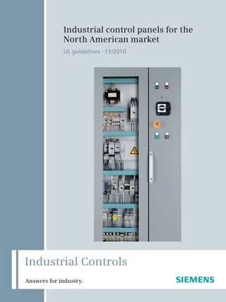
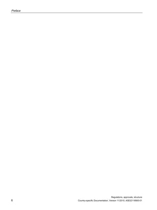
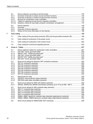
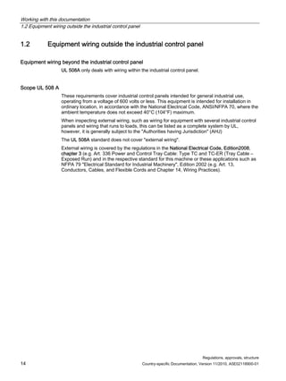
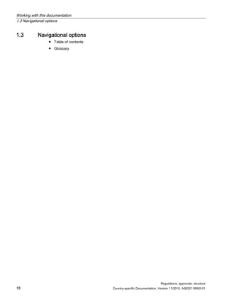
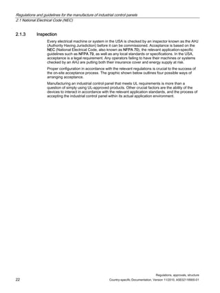
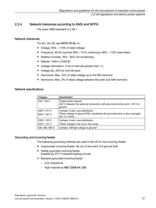
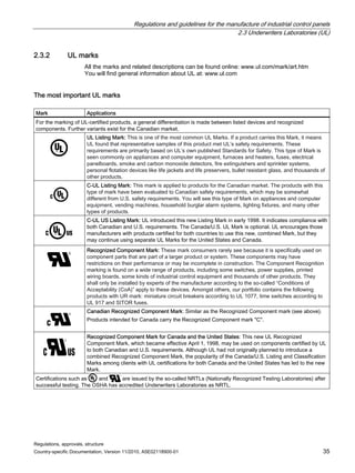
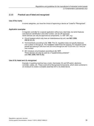
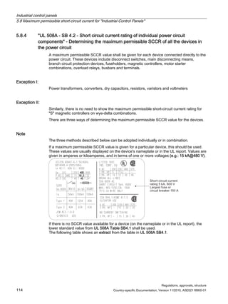
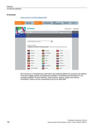
Options for inspecting industrial control panels in a commissioning context
In most cases, the customer in the USA will specify the type of acceptance. If the type of
acceptance is not mentioned in the specification, you should negotiate with the customer as
considerable costs may result from many forms of acceptance.
RPPLVVLRQLQJSUHUHTXLVLWHIRUHQGFXVWRPHU
RVWH[SHQGLWXUHV
7LPHH[SHQGLWXUHV
IRUILHOGDFFHSWDQFH
$GMXVWPHQWSRVVLELOLW
5HFRPPHQGDWLRQ
$FFHSWDQFHRSWLRQVIRU2(0V
)LHOGLQVSHFWLRQE$+-
0DQGLIIHUHQW
VVWHPV
/LWWOH8/NQRZOHGJH *RRG8/NQRZOHGJH
9HUODUJHTXDQWLWLHV
1RWSRVVLEOH 3RVVLEOHWRJHWKHU
ZLWKPDQXIDFWXUHU
3RVVLEOHILHOG
LQVSHFWLRQUHTXLUHG
3RVVLEOHUHQHZHG
ILHOGLQVSHFWLRQUHTXLUHG
HUWLILHG
PDQXIDFWXUHURI
DQ,3
3UHOLPLQDU
DFFHSWDQFHE
8/LQVSHFWRUDW
WKHIDFWRUVLWH
)LHOGLQVSHFWLRQ
E$+-
LQWKH86$
,3 OLVWHG
ZLWKODEHOE
157/
RQIRUPLWWRWKHDFWXDOVWDQGDUGVRIVDIHWLQHOHFWULFDOLQVWDOODWLRQV
DFFRUGLQJWRWKH26+$UHJXODWLRQV E$+-
,QGXVWULDORQWURO3DQHO
1DWLRQDOO5HFRJQL]HG7HVWLQJ/DERUDWRULHV
$XWKRULWKDYLQJMXULVGLFWLRQ](https://image.slidesharecdn.com/guide-to-industrial-control-panels-230922040019-c60a1df7/85/Guide-to-Industrial-Control-Panels-pdf-23-320.jpg)
![Regulations and guidelines for the manufacture of industrial control panels
2.3 Underwriters Laboratories (UL)
Regulations, approvals, structure
40 Country-specific Documentation, Version 11/2010, A5E02118900-01
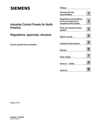
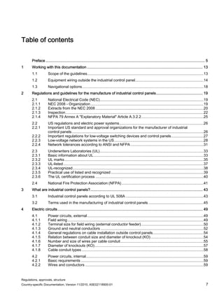
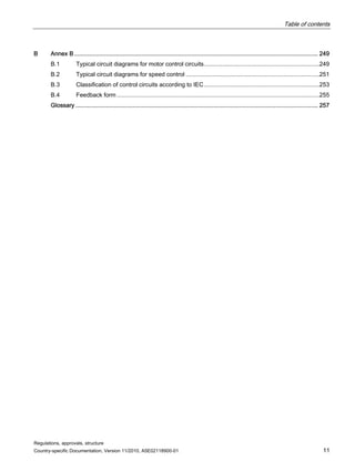
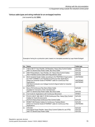
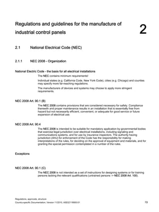
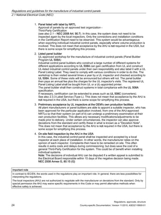
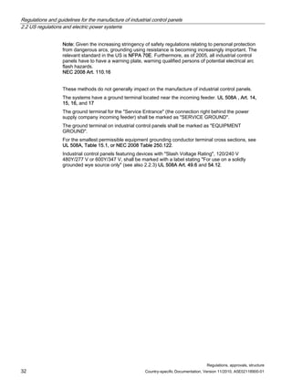
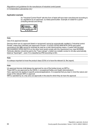
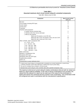
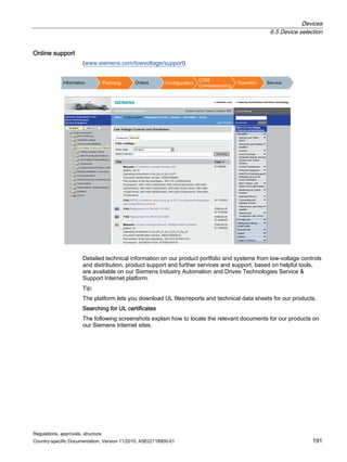
2.3.6 The UL certification process
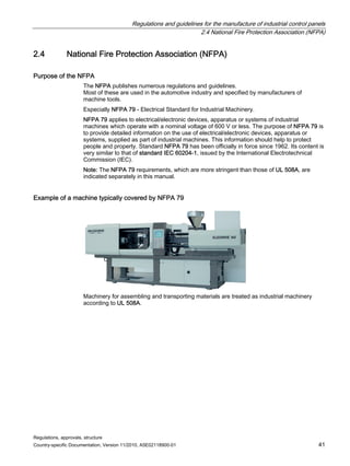
Product presentation
Thorough preparations in the presentation phase save time and money in the inspection and
test phase.
7KHDSSOLFDQWVXEPLWVWKHUHTXHVW SURGXFWGHVFULSWLRQ
FLUFXLWGLDJUDPVSKRWRJUDSKVLQVWUXFWLRQVEURFKXUHV
HWF DORQJZLWKSDUWVOLVWVZLWK8/VWDWXVRI
PDWHULDOVGHYLFHV
,WLVLPSRUWDQWWRVXEPLWLQIRUPDWLRQDERXWDQYDULDWLRQV
WKHVDPHVVWHPEXWODUJHURUVPDOOHULQWHUPVRIN:
IRUH[DPSOH DQGDQRSWLRQVDWWKHVDPHWLPHHYHQLI
IXOOGHWDLOVRIWKHVHDUHQRWHWDYDLODEOH
8/GHFLGHRQWKHWKHUHOHYDQWWHVWSURJUDPDSSOLFDEOH
VWDQGDUG1 DWHJRURQWURO1XPEHU SURGXFWPRGHO
DQGGRFXPHQWDWLRQDVZHOODVDQHVWLPDWLRQRIFRVWV
2QFHWKHDJUHHPHQWRQPDQXIDFWXULQJVXSHUYLVLRQ
/DJUHHPHQW KDVEHHQVLJQHGDOOWKHUHTXLUHG
PRGHOVDQGGRFXPHQWVDUHVXEPLWWHG
8/H[DPLQHDQGWHVWWKHSURGXFW
'RHVWKHSURGXFWPHHW
WKHUHTXLUHPHQWV
12
3URMHFWRIRPSOHWLRQ/HWWHU
,3, LQLWLDOLQVSHFWLRQ
(DUO$XWKRUL]DWLRQ/HWWHU
5HSRUWZLWKWHVWUHVXOWV GRFXPHQWDWLRQ
'HYLDWLRQVUHSRUW
'HVLJQFRUUHFWLRQV
5HVXEPLVVLRQ
(6
3UHOLPLQDU
,QYHVWLJDWLRQ
The word product covers
● Devices (e.g. a circuit breaker)
● Parts of a device (e.g. an auxiliary contact for a circuit breaker)
● Combinations of several devices (e.g. a machine control system)](https://image.slidesharecdn.com/guide-to-industrial-control-panels-230922040019-c60a1df7/85/Guide-to-Industrial-Control-Panels-pdf-40-320.jpg)
![What are industrial control panels?
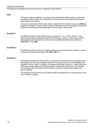
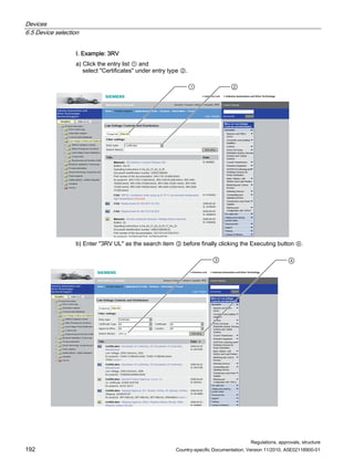
3.1 Industrial control panels according to UL 508A
Regulations, approvals, structure
44 Country-specific Documentation, Version 11/2010, A5E02118900-01
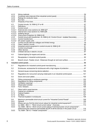
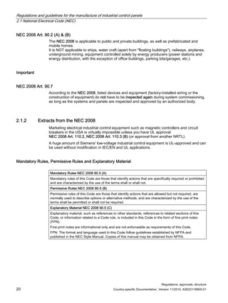
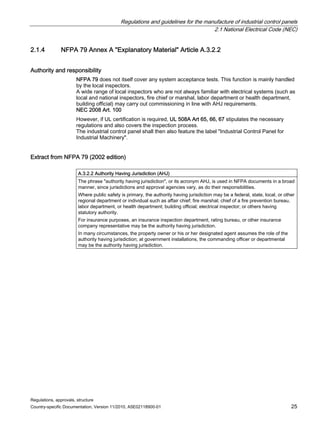
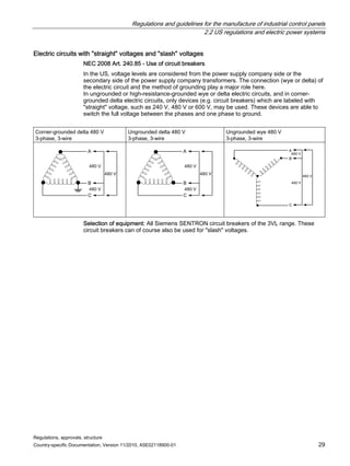
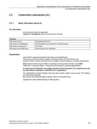
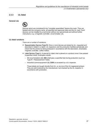
UL 508A Supplement und Appendix
● Supplement SA – Specific Component Requirements – requirements for industrial control
equipment in industrial control panels. Only products listed here may be used.
● Supplement SB – Short Circuit Current Ratings for Industrial Control Panels – short circuit
requirements for industrial control panels – see also NEC 2008 Art. 409.
● Annex A – Standards for Components – standards that are of relevance to industrial
control equipment used in industrial control panels
● Annex B – Use of Components NOT UL Listed or Recognized in Industrial Control
Panels – unlisted industrial control equipment
Industrial control panels for general applications
UL 508A Art. 1.1
According to UL 508A industrial control panels are suitable for all general industrial
applications, maximum 600 V, for installation in normal ambient conditions with a maximum
room temperature of 40 °C [104 °F] and in accordance with the National Electrical Code,
ANSI/NFPA 70.
Exceptions
UL 508A Art. 1.5
The standard does not apply to explosion-protected equipment (hazardous / classified
locations) as defined in NEC 2008 Art. 500. These systems are addressed in UL 698. The
standard does not apply to fire pump controllers. These are addressed in UL 218 Standard
for Fire Pump Controllers.](https://image.slidesharecdn.com/guide-to-industrial-control-panels-230922040019-c60a1df7/85/Guide-to-Industrial-Control-Panels-pdf-44-320.jpg)
![Regulations, approvals, structure
Country-specific Documentation, Version 11/2010, A5E02118900-01 49
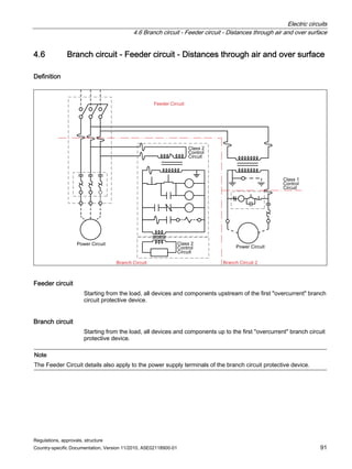
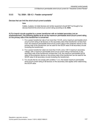
Electric circuits 4
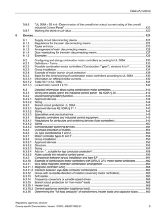
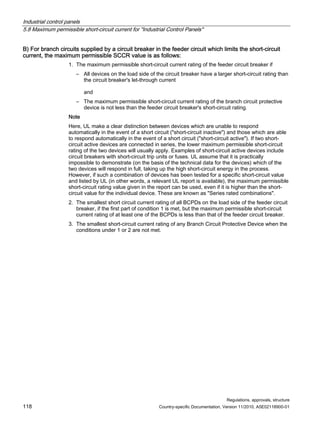
4.1 Power circuits, external
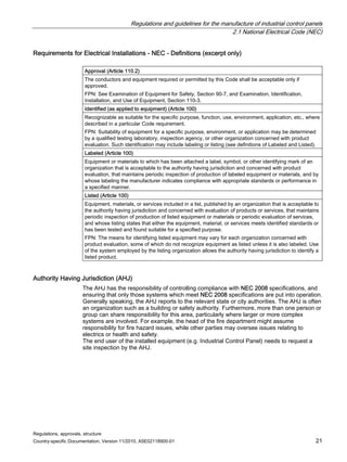
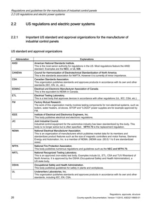
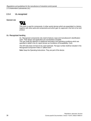
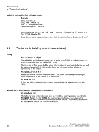
4.1.1 Field wiring
Field wiring terminals
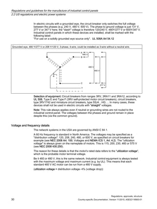
There shall be one termination point for each external wire requiring connection. Terminals
for copper wires shall be approved according to UL 486A, and those for aluminum wires
according to UL 486B. All terminals intended for the field wiring shall be marked in terms of
the wire material (Cu, Alu, etc.) for which they are intended.
Torques: (Torque in lb-in [1 Nm = 8.85 lb-in]; 1 lb-ft = 12 lb-in)
Terminals for industrial control equipment shall be tested according to UL 486E.
New: All terminals for finely stranded wires, such as welding cables, Diesel Locomotive
Cable (DLC) or those marked as Flexing or Class K, shall be tested according to
UL 486A and UL 486B and labeled accordingly.
Marking field wiring
Marking field wiring: UL 508A Art. 54
Line or Load Terminal.
Torques of terminal screws.
Temperatures of wire.
Note: Only a current carrying capacity of 75 ºC is really ever used now for terminal sizing
(60 ºC is hardly used any more); wires approved for higher temperatures, such as 90 ºC or
105 ºC, may only be loaded (calculated) for 75 ºC current carrying capacity.
Wire material includes copper, aluminum and copper-clad aluminum.](https://image.slidesharecdn.com/guide-to-industrial-control-panels-230922040019-c60a1df7/85/Guide-to-Industrial-Control-Panels-pdf-49-320.jpg)
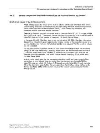
![Electric circuits
4.1 Power circuits, external
Regulations, approvals, structure
Country-specific Documentation, Version 11/2010, A5E02118900-01 51
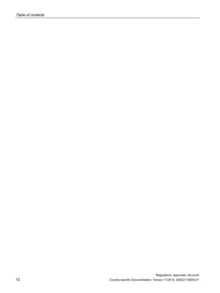
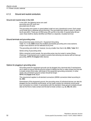
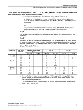
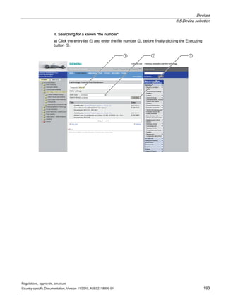
Wire size and rated load carrying capacity
Rated values,
insulated cables
AWG (mm2)
① Permissible current
carrying capacity
according to
NEC 2008, Tab. 310.16
Cu 75 °C
[A]
② Permissible current carrying
capacity
for load feeders
= Column (1)/1.25
[A]
③ Maximum
short-circuit protection
for non-motor loads:
circuit breakers or
fuses
[A]
14 (2.1) 15 12 15
12 (3.3) 20 16 20
10 (5.3) 30 24 30
8 (8.4) 50 40 50
6 (13.3) 65 52 65
4 (21.2) 85 68 85
3 (26.7) 100 80 100
2 (33.6) 115 92 115
1 (42.2) 130 104 130
1/0 (53.5); (also # 0) 150 120 150
2/0 (67.4); (also # 00) 175 140 175
3/0 (85); (also # 000) 200 160 200
4/0 (107); (also # 0000) 230 184 230
250 kcmil (127) 255 204 255
300 kcmil (152) 285 228 285
350 kcmil (177) 310 248 310
400 kcmil (203) 335 268 335
*500 kcmil (253) 380 304 380
* 500 kcmil (MCM) is (usually) the largest external wire
① Values apply for not more than 3 wires routed in a conduit. Terminals for larger conductor cross sections shall be
provided for systems with 2 or more conductors per phase in one conduit, e.g. 6 or 9. NEC 2008, Tab. 310.16
② Wires should be sized for 125% of the load current. NEC 2008 Art. 430.22 (A)
③ According to NEC 2008 Art. 240.3](https://image.slidesharecdn.com/guide-to-industrial-control-panels-230922040019-c60a1df7/85/Guide-to-Industrial-Control-Panels-pdf-51-320.jpg)
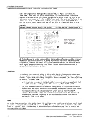
![Electric circuits
4.1 Power circuits, external
Regulations, approvals, structure
Country-specific Documentation, Version 11/2010, A5E02118900-01 53
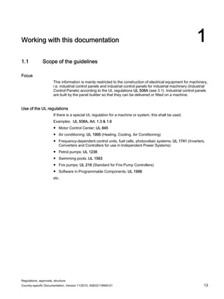
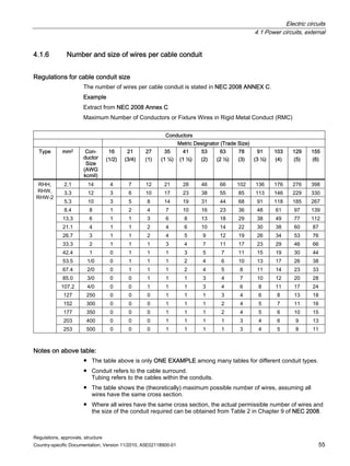
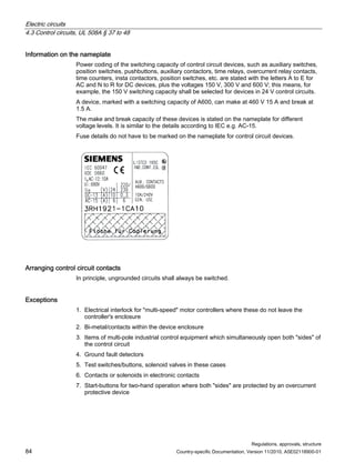
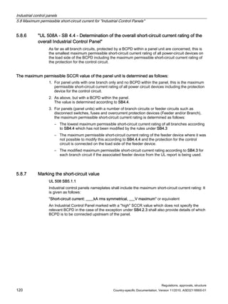
Size of equipment ground terminal UL 508A, Table 15.1
Size of equipment grounding or bonding wire of grounded parts (minimum)
Copper Aluminum
Maximum ampere rating of
overcurrent protection for field
wires supplying the industrial
control panel AWG or kcmil [mm2] AWG or kcmil [mm2]
15 14 2.1 12 3.3
20 12 3.3 10 5.3
30 10 5.3 8 8.4
40 10 5.3 8 8.4
50 10 5.3 8 8.4
100 8 8.4 6 13.3
200 6 13.3 4 21.2
300 4 21.2 2 33.6
400 3 26.7 1 42.4
500 2 33.6 1/0 53.5
600 1 42.4 2/0 67.4
800 1/0 53.5 3/0 85.0
1000 2/0 67.4 4/0 107.2
1200 3/0 85.0 250 kcmil 127
1500 4/0 107.2 350 177
2000 250 kcmil 127 400 203
2500 350 177 600 304
3000 400 203 600 304
4000 500 253 800 405
5000 700 355 1200 608
6000 800 506 1200 608](https://image.slidesharecdn.com/guide-to-industrial-control-panels-230922040019-c60a1df7/85/Guide-to-Industrial-Control-Panels-pdf-53-320.jpg)
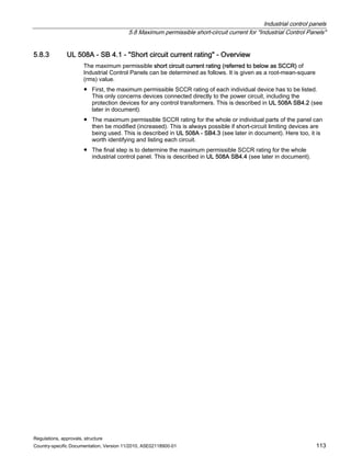
![Electric circuits
4.1 Power circuits, external
Regulations, approvals, structure
54 Country-specific Documentation, Version 11/2010, A5E02118900-01
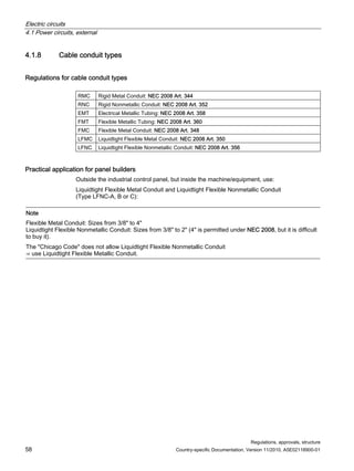
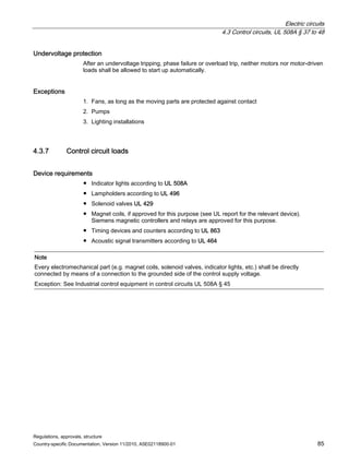
4.1.4 General regulations on cable installation outside control panels
Number of cables in conduits
NEC 2008 Annex C specifies how many cables shall be installed, the cross section and
installation types, and the cable conduit cross sections.
This determines both the size and number of cable conduits. The information provided
makes it possible to determine the number and size of the Knock outs. The Knock outs
shall then be set up in the enclosure according to UL 508A Art. 19.
Comments:
Please consider the issue of spare cables.
Openings for external wiring
Up to type 3R, there are already openings in the enclosure. These are, however, only
permitted on the underside of the panel (e.g. for cable entry), or on the sides, below current-
conducting parts.
4, 4X, 12, 13 enclosure types do not have openings. During installation, these are provided
by an electrician as needed. See UL 508 Art. 25.2.
Take care with the dimensions: The cable conduit sizes are given in inches, e.g. conduit
size 3/4, 1, 1-1/4. These are not the outer diameters of the conduits!
These figures are trade sizes.
Exception: Grounding wires are not current-conducting and may be laid outside the cable
conduit under certain circumstances. NEC 2008 Art. 300.3 (B) (2)
4.1.5 Relation between conduit size and diameter of knockout (KO)
Conduit size and diameter of the Knockouts (KO)
Conduit size
[inch]
KO diameter
[inch]
Metric size designation
1/2 0.859 16
3/4 1.094 21
1 1.359 27
1-1/4 1.719 35
1-1/2 1.958 41](https://image.slidesharecdn.com/guide-to-industrial-control-panels-230922040019-c60a1df7/85/Guide-to-Industrial-Control-Panels-pdf-54-320.jpg)
![Electric circuits
4.1 Power circuits, external
Regulations, approvals, structure
56 Country-specific Documentation, Version 11/2010, A5E02118900-01
Number of conductors Filling rate for all conductor types (as %)
1 53 %
2 31 %
2 40 %
Example
Wire size AWG 10 Type RHH,
number of wires 6,
gives a 40% filling rate.
This means (in theory) that at least 15 wires could be contained in the Conduit (6 ≙ 40%
of 15).
Taken from table for conduit type RMC ≙ Rigid Metal Conduit.
Conduittyp RMC ≙ Rigid Metal Conduit
Wires with different cross sections in a conduit.
The actual permissible number of wires can be obtained using Tables 5 and 5a (diameter
and cross sections) and Table 4.
All tables are contained in NEC 2008 Chapter 9.
The calculation method is as follows:
a) Determine the relevant cross section according to the NEC tables.
b) Add together the individual cross sections obtained.
c) Extrapolate the total cross section calculated in step b) in terms of an filling rate
(in precentage) based on the required conduit cross section.
d) The conduit cross section to be used shall be greater than or equal to the value
derived under step c).
Example
Number Wire size and type Cross section according to
Table 5 [inch2]
Total cross section
[inch2]
4 12 AWG THWN 0.0133 0.0532
3 8 AWG TW 0.0437 0.1311
3 6 AWG THW 0.0726 0.2178
∑ 0.4021
Table 1 gives an filling rate of 40%.
Table 4 gives:
Conduit size 1 1/4 or 35.
Conduit type RMC ≙ Rigid Metal conduit
Maximum usable cross section at 40% filling rate is 0.61 inch2](https://image.slidesharecdn.com/guide-to-industrial-control-panels-230922040019-c60a1df7/85/Guide-to-Industrial-Control-Panels-pdf-56-320.jpg)
![Electric circuits
4.1 Power circuits, external
Regulations, approvals, structure
Country-specific Documentation, Version 11/2010, A5E02118900-01 57
4.1.7 Diameter of knockouts (KO)
UL 508A Tab. 11.1 – Knockouts or hole sizes and dimensions of bushings
Dimensions of bushings
Trade size of conduits Knockout or hole diameter
Overall diameter Height
[mm] [inch] [mm] [inch] [mm] [inch] [mm] [inch]
21.3 1/2 22.3 7/8 25.4 1 9.5 3/8
26.7 3/4 27.8 1-3/32 31.4 1-15/64 10.7 27/64
33.4 1 34.5 1-23/64 40.5 1-19/32 13.1 33/64
42.3 1-1/4 43.7 1-23/32 48.2 1-15/32 14.3 9/16
48.3 1-1/2 50.0 1-31/32 56.0 2-13/64 15.1 19/32
60.3 2 62.7 2-15/32 68.7 2-45/64 15.9 5/8
73.0 2-1/2 76.2 3 81.3 3-7/32 19.1 3/4
88.9 3 92.1 3-5/8 96.4 3-7/8 20.6 13/18
101.6 3-1/2 104.8 4-1/8 112.7 4-7/16 25.8 15/16
114.0 4 117.5 4-5/8 126.2 4-31/32 25.4 1
127.0 4-1/2 130.2 5-1/8 140.9 5-35/64 27.0 1-1/16
141.3 5 142.9 5-5/8 158.0 6-7/32 30.2 1-3/16
168.3 6 171.5 6-3/4 183.4 7-7/32 31.8 1-1/4](https://image.slidesharecdn.com/guide-to-industrial-control-panels-230922040019-c60a1df7/85/Guide-to-Industrial-Control-Panels-pdf-57-320.jpg)
![Electric circuits
4.2 Power circuits, internal
Regulations, approvals, structure
60 Country-specific Documentation, Version 11/2010, A5E02118900-01
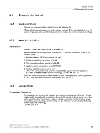
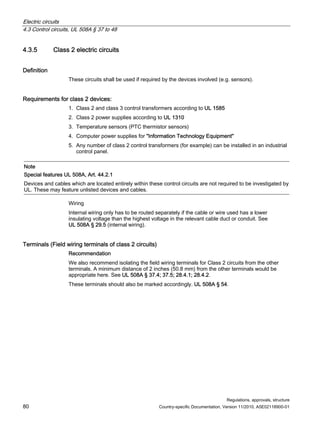
Internal wiring – details and exceptions
Note: Some UL-recognized devices are only suitable for factory wiring. This means that the
terminals may only be wired in the factory or by the panel builder. Instructions can then be
found in the UL report.
Within the industrial control panel, UL 508A accepts several wires per termination point
provided that these are safely connected. Safe connection is established by the UL inspector
using a manual pull test. UL 508A, Art. 29.3.6
The wires shall be routed away from sharp edges; all points of contact should be free of
burrs (use edge protection); rubber sleeves should be used for holes.
UL 508A, Art. 29.4
Wires for different voltages shall either be laid separately or all wires shall be designed for
the highest voltage.
Field wiring: UL 508A Art. 25 and NEC Chapter 3
Wiring within the industrial control panel: Table 25.1 in UL 508A specifies the distance
between the field wiring terminal and the enclosure wall within the industrial control panel.
Wire bending space
Minimum bending space, terminal to wall, inches [mm]
Wires per terminala
Size of wire
AWG or MCM
[mm2]
1 2 3 4 or more
14 – 10 (2.1 – 5.3) Not specified a a a
8 – 6 (8.4 – 13.3) 1-1/2 (38) a a a
4 – 3 (21.2 – 26.7) 2 (51) a a a
2 (33.6) 2-1/2 (64) a a a
1 (42.4) 3 (76) a a a
1/0 (53.5) 5 (127) 5 (127) 7 (178)
2/0 (67.4) 6 (152) 6 (152) 7-1/2 (191)
3/0 (85.0) 7 (178) 7 (178) 8 (203)
4/0 (107.2) 7 (178) 7 (178) 8-1/2 (216)
250 (127) 8 (203) 8 (203) 9 (229) 10 (254)
300 (152) 10 (254) 10 (254) 11 (279) 12 (305)
350 (177) 12 (305) 12 (305) 13 (330) 14 (356)
400 (203) 12 (305) 12 (305) 14 (356) 15 (381)
500 (253) 12 (305) 12 (305) 15 (381) 16 (406)
600 (304) 14 (356) 16 (406) 18 (457) 19 (483)
700 (355) 17 (356) 16 (406) 20 (508) 22 (559)
750 – 800 (380 – 405) 18 (457) 19 (483) 22 (559) 24 (610)
900 (456) 18 (457) 19 (483) 24 (610) 24 (610)
1000 (506) 20 (508) - - -
1250 (633) 22 (559) - - -
1500 – 2000 (760 – 1013) 24 (610) - - -
NOTE: ″–″ indicates no value established
a Conductors smaller than 1/0 AWG shall not be connected in parallel](https://image.slidesharecdn.com/guide-to-industrial-control-panels-230922040019-c60a1df7/85/Guide-to-Industrial-Control-Panels-pdf-60-320.jpg)
![Electric circuits
4.2 Power circuits, internal
Regulations, approvals, structure
62 Country-specific Documentation, Version 11/2010, A5E02118900-01
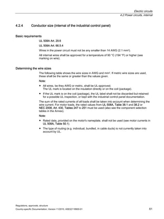
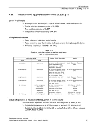
4.2.5 Ratings for conductor sizes
General rule
Internal wires (ambient temperature of up to 40 °C, measured approx. 1.2 m outside the
industrial control panel) UL 508A, Chapter 29.6
Wire sizes and current carrying capacity - UL 508A, Table 28.1
Wire size 60 °C (140 °F) 75 °C (167 °F)
AWG [mm2] Copper [A] Aluminum [A] Copper [A] Aluminum [A]
14 (2.1) 15 - 15 -
12 (3.3) 20 15 20 15
10 (5.3) 30 25 30 25
8 (8.4) 40 30 50 40
6 (13.3) 55 40 65 50
4 (21.2) 70 55 85 65
3 (26.7) 85 65 100 75
2 (33.6) 95 75 115 90
1 (42.4) 110 85 130 100
1/0 1) (53.5) - - 150 120
2/0 (67.4) - - 175 135
3/0 (85.0) - - 200 155
4/0 (107.2) - - 230 180
250 kcmil (127) - - 255 205
300 (152) - - 285 230
350 (177) - - 310 250
400 (203) - - 335 270
500 (253) - - 380 310
600 (304) - - 420 340
700 (355) - - 460 375
750 (380) - - 475 385
800 (405) - - 490 395
900 (456) - - 520 425
1000 (506) - - 545 445
1250 (633) - - 590 485
1500 (760) - - 625 520
1750 (887) - - 650 545
2000 (1013) - - 665 560
NOTES –
1 For multiple-conductors of the same size (1/0 AWG or larger) at a terminal, the ampacity is equal to the value in this
table for that conductor multiplied by the number of conductors that the terminal is able to accommodate](https://image.slidesharecdn.com/guide-to-industrial-control-panels-230922040019-c60a1df7/85/Guide-to-Industrial-Control-Panels-pdf-62-320.jpg)
![Electric circuits
4.2 Power circuits, internal
Regulations, approvals, structure
Country-specific Documentation, Version 11/2010, A5E02118900-01 63
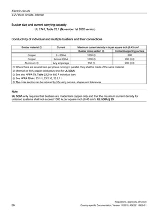
UL 508A, Art. 66.5.4
Wires in the power circuit shall not be any smaller than # 14 AWG (2.1 mm2).
Exceptions
Only for control panels for Industrial Machinery.
Wires in the power circuit may be designed using # 16 AWG and # 18 AWG if they comply
with the conditions stated in Table 66.1A.
Wire size and current carrying capacity – exceptions
UL 508A, Table 66.1A
Current load and protection for power circuits with 16 AWG and 18 AWG cables
Cable Load type Max branch circuit protection in amps Trip class of motor overload
protection c)
Size [A]
16 AWG 8 Not motor a) 10 A -
8 Motor a) - see UL 508A Tab. 31.1 Class 10
5.5 Motor a) - see UL 508A Tab. 31.1 Class 20
18 AWG 5.6 Not motor b) - 7 A -
5 Motor b) - see UL 508A Tab. 31.1 Class 10
3.5 Motor b) - see UL 50 A Tab. 31.1 Class 20
a) Circuit breaker with thermal delay labeled for protecting 16 AWG or 18 AWG or class CC, J or T fuses
b) Circuit breaker with thermal delay labeled for protecting 18 AWG or class CC, J or T fuses
c) Class 10: Overload protection trips in 10 seconds at 6 times the current setting.
Class 20: Overload protection trips in 20 seconds at 6 times the current setting.
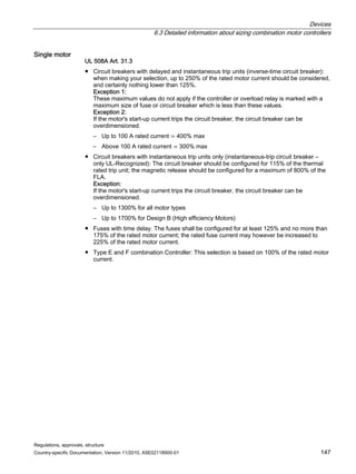
Application example for up to 600 V
Practical application for up to 600 V:
● Internal wiring according to UL 508A Tab. 28.1
● External wiring, NEC 2008 Table 310.16, up to # 1 AWG (110 A) = 60 °C column,
from # 1/0 AWG (150 A) = 75 °C column PLUS 25% (or x 125%)
– Temperature in excess of 30 ℃; see correction factor under
NEC 2008 Table 310.17
– Correction factor for more than 3 conductors in one cable route, see
NEC 2008 Table 310.15 (B) (2) (a)
● Conductors in parallel: # 1/0 AWG and larger, NEC 2008 310.4,
conditions for parallel cables: same cable materials, same cross section, same insulation,
same connecting type.](https://image.slidesharecdn.com/guide-to-industrial-control-panels-230922040019-c60a1df7/85/Guide-to-Industrial-Control-Panels-pdf-63-320.jpg)
![Electric circuits
4.2 Power circuits, internal
Regulations, approvals, structure
Country-specific Documentation, Version 11/2010, A5E02118900-01 65
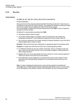
4.2.7 Ampacity of bus bars
As far as UL 508A, NFPA 79 or NEC 2008 are concerned, there are currently no clear rules
for dealing with non type-tested busbars. The only guidance in this area is provided by the
November 1, 2002 version of UL 1741.
Conditions for using busbars according to UL 1741
UL 1741 (Inverters, Converters and Controllers for use in Independent Power Systems)
contains further requirements:
Note: UL 1741 permits the use of aluminum busbars; UL 508A only permits copper busbars.
UL 1741, Table 23.2
Size of individual bars up to maximum 800 A
Copper busbars Aluminum busbars ②
Size ① Cross section ③ Size ① Cross section ③
Current
[mm] [inch] [mm2] [inch2] [mm] [inch] [mm2] [inch2]
225 3.2 x 22.2 0.125 x
0.875
70.3 0.109 6.4 x 22.2 0.250 x
0.875
141.3 0.219
400 6.4 x 38.1 0.125 x
1.500
242.,0 0.375 6.4 x 50.8 0.250 x
2.000
322.6 0.500
600 6.4 x 50,8 0.250 x
2.000
322.6 0.375 See table 23.1 See table 2
3.1
518.1 0.800
800 6.4 x 76.2 0.250 x
3.000
483.9 0.750 See table 23.1 See table 2
3.1
688.4 1.067
① Bars with other dimensions can be approved if they have the same cross section and an equivalent mechanical
strength.
② Minimum of 55% copper conductivity (not for UL 508A)
③ The cross section can be reduced by 5% using corners, shapes and tolerances.
Note: Several parallel busbars shall have a minimum contact supporting surface (overlap) of no less than 6.45 cm2
(1 square inch) per 200 A.
UL 1741 Art. 23.2.10
The cross sections of bars may be reduced using slots and holes (with or without screws), if:
● The remaining material is at least 70% of the cross section given above.
● The remaining material volume is at least 93% over any 152 mm (6 inch) length.
For the requirements relating to fixing elements, such as screws, rivets, spring rings, cup
washers and shims, see UL 1741 Art. 23.](https://image.slidesharecdn.com/guide-to-industrial-control-panels-230922040019-c60a1df7/85/Guide-to-Industrial-Control-Panels-pdf-65-320.jpg)
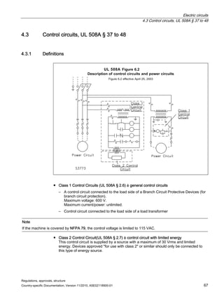
![Electric circuits
4.3 Control circuits, UL 508A § 37 to 48
Regulations, approvals, structure
78 Country-specific Documentation, Version 11/2010, A5E02118900-01
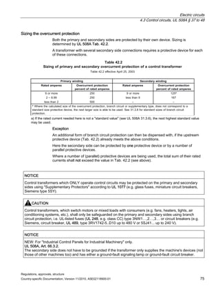
4.3.4 Control circuits with low voltages and limited energy
(Low-Voltage Limited Energy Circuits)
For DC and AC circuits
Conditions
UL 508A, Art. 43.2.2
Cable materials that are not listed shall be routed separately. Listed cable materials can be
routed in one cable duct with other electric circuits if they are designed for the maximum
voltage of all electric circuits.
1. These electric circuits shall be routed in such a way that they are insulated from other
electric circuits (see above for exception) and shall be operated by insulated secondary
current sources (e.g. control transformers, DC power supplies, batteries (UL 1989),
lithium batteries (UL 1641), current transformers (UL 506), current transformers with 5 A
on secondary side).
2. The maximum open circuit secondary voltages shall not exceed an rms value of
30 VAC or 42.4 V (DC or AC peak value). UL 508A, Art. 43.1.2
3. The overload protection equipment shall not be larger than specified in UL 508A,
Table 43.1,
(glass fuse, 5SX, 5SY or 5SP miniature circuit breaker, Supplementary Protectors,
UL 1077).
Device requirements
● Transformer according to Chapter 4.3.3.1
● Power supply according to Chapter 4.3.3.2
● Sealed battery according to UL 1989
● Lithium battery according to UL 1642
● Current transformer according to UL 506
● Current transformer with 5 A secondary current (...A/5 A)
The maximum no-load or open circuit voltage shall not exceed 30 Vrms, 42.4 V peak value
or 42.4 VDC.
Each of these circuits shall have overcurrent protection according to UL 508A Tab. 43.1.
UL 508A, Table 43.1
Secondary peak voltage in volts (open) Overload protection equipment, amperes
0 – 20 5
20.1 – 42.4 100/V [A] ①
① V equals the peak voltage or, with DC, the secondary no-load or open circuit voltage.](https://image.slidesharecdn.com/guide-to-industrial-control-panels-230922040019-c60a1df7/85/Guide-to-Industrial-Control-Panels-pdf-78-320.jpg)
![Electric circuits
4.3 Control circuits, UL 508A § 37 to 48
Regulations, approvals, structure
82 Country-specific Documentation, Version 11/2010, A5E02118900-01
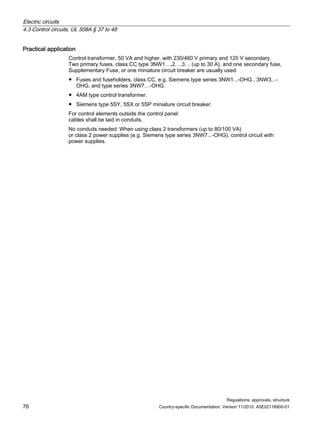
● Fuse details do not have to be marked on the nameplate for control circuit devices.
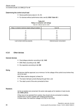
Groups for alternating current
Rating codes for AC control circuit contacts at 50 and 60 Hz;
(UL 508A Table 45.2)
Maximum make or break current [A]
120 V 240 V 480 V 600 V
Maximum volt-
amperes
*)
Contact
rating
Code
designation
Thermal
continuous
test current
[A]
Make Break Make Break Make Break Make Break Make Break
A150 10 60 6.0 - - - - - - 7200 720
A300 10 60 6.0 30 3.0 - - - - 7200 720
A600 10 60 6.0 30 3.0 15 1.5 12 1.2 7200 720
B150 5 30 3.0 - - - - - - 3600 360
B300 5 30 3.0 15 1.5 - - - - 3600 360
B600 5 30 3.0 15 1.5 7.5 0.75 6 0.60 3600 360
C150 2.5 15 1.5 - - - - - - 1800 180
C300 2.5 15 1.5 7.5 0.75 - - - - 1800 180
C600 2.5 15 1.5 7.5 0.75 3.75 0.375 3.0 0.30 1800 180
D150 1.3 3.6 0.6 - - - - - - 432 72
D300 1.0 3.6 0.6 1.8 0.30 - - - - 432 72
E150 0.5 1.8 0.3 - - - - - - 216 36
*) The numerical suffix designates the maximum voltage design values, which shall be 600, 300, 150 volts for suffixes 600,
300, and 150, respectively.](https://image.slidesharecdn.com/guide-to-industrial-control-panels-230922040019-c60a1df7/85/Guide-to-Industrial-Control-Panels-pdf-82-320.jpg)
![Electric circuits
4.3 Control circuits, UL 508A § 37 to 48
Regulations, approvals, structure
Country-specific Documentation, Version 11/2010, A5E02118900-01 83
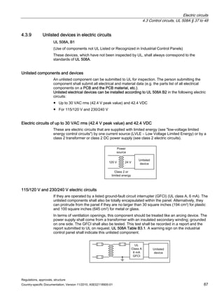
Groups for direct current
Contact rating codes for DC control circuit contacts
(UL 508A Table 45.3 )
Maximum make or break current [A]
Thermal
continuous
test current
Maximum make or
break VA at
300 volts or less
*)
Contact rating code
designation
[A]
125 V 250 V 301 to 600 volts
[VA]
N150 10 2.2 - - 275
N300 10 2.2 1.1 - 275
N600 10 2.2 1.1 0.40 275
P150 5.0 1.1 - - 138
P300 5.0 1.1 0.55 - 138
P600 5.0 1.1 0.55 0.20 138
Q150 2.5 0.55 - - 69
Q300 2.5 0.55 0.27 - 69
Q600 2.5 0.55 0.27 0.10 69
R150 1.0 0.22 - - 28
R300 1.0 0.22 0.11 - 28
*) The numerical suffix designates the maximum voltage design values, which shall be 600, 300, 150 volts for suffixes 600,
300, and 150, respectively.
Table for converting horsepower (hp) to volt-amperes (VA)
Table 45.4
Conversion of horsepower to VA load ratings
Table 45.4 effective April 25, 2003
A
V
,
g
n
i
t
a
r
e
r
e
p
m
a
-
t
l
o
v
g
n
i
d
n
o
p
s
e
r
r
o
C
r
e
w
o
p
e
s
r
o
h
,
g
n
i
t
a
r
h
c
t
i
w
S
4
4
1
0
1
/
1
2
8
1
8
/
1
1
1
2
6
/
1
8
7
2
4
/
1
5
4
3
3
/
1
0
7
4
2
/
1
2
6
6
4
/
3
8
6
7
1
UL 508A §](https://image.slidesharecdn.com/guide-to-industrial-control-panels-230922040019-c60a1df7/85/Guide-to-Industrial-Control-Panels-pdf-83-320.jpg)
![Electric circuits
4.3 Control circuits, UL 508A § 37 to 48
Regulations, approvals, structure
88 Country-specific Documentation, Version 11/2010, A5E02118900-01
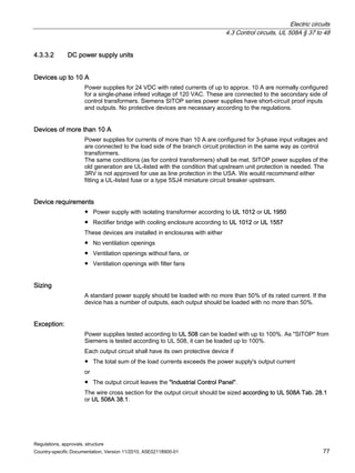
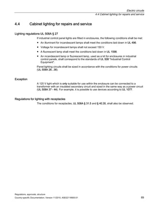
Unlisted devices are not permitted as:
UL 508A, B1
● Devices that switch power circuits (e.g. motor loads, short circuit and ground fault)
● Devices in electric circuits with particular safety regulations
(e.g. cathode ray tubes, flammable gases, high pressure [greater than 300 psi –
2.08 Mpa])
● Devices which are tested for other applications
● Devices with links to power circuits (i.e. do not correspond to UL 508A)
● Devices which are installed insulated from the ground fault circuit interrupter
Plastic parts in direct contact with live parts (installation parts) shall be tested in accordance
with UL 508A (flame class according to UL 94).](https://image.slidesharecdn.com/guide-to-industrial-control-panels-230922040019-c60a1df7/85/Guide-to-Industrial-Control-Panels-pdf-88-320.jpg)
![Industrial control panels
5.2 Enclosures, accessories for enclosures with a high degree of protection
Regulations, approvals, structure
98 Country-specific Documentation, Version 11/2010, A5E02118900-01
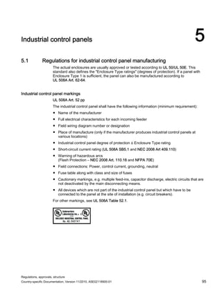
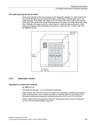
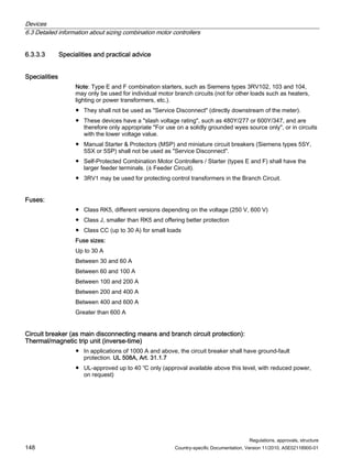
Special features:
Degrees of protection are specified both in NEC 2008 and by UL using type numbers, such
as type 12. The degree of protection is, however, stated in most manufacturers' catalogs
using the NEMA designation, such as NEMA type 12 (NEMA ICS-6).
Note:
● UL vs. NEMA: An enclosure built in accordance with NEMA (standard ICS-6) is not
automatically UL-listed. It shall be examined by UL for the enclosure rating (UL type 1)
and tested (UL type 3R, 12, 4, etc.).
● For UL / NEMA type 1: If there are uninsulated, current-carrying conductors in the
industrial control panel, the panel shall have a roof to protect against falling dirt.
UL 508A, Art. 21.2.1
● If a water-cooled converter is installed in an industrial control panel, mechanisms shall be
put into place to ensure that water does not touch any of the current-conducting parts
should a water pipe burst (preferably fit these in a separate panel).
[not in UL 508A – but applied] UL 1741
● New: In UL 508A – swiveling mounting panels (only for Industrial Control Panels for use
in Industrial Machinery). It shall be possible for these mounting panels to swivel by more
than 110 degrees.
UL 508A, Art. 66.1.3
● New: In UL 508A – 3RX, 3SX and 3X are type 3 with extra corrosion protection
requirements.](https://image.slidesharecdn.com/guide-to-industrial-control-panels-230922040019-c60a1df7/85/Guide-to-Industrial-Control-Panels-pdf-98-320.jpg)
![Industrial control panels
5.4 Regulations for noncurrent carrying metal parts in an industrial control panel
Regulations, approvals, structure
Country-specific Documentation, Version 11/2010, A5E02118900-01 101
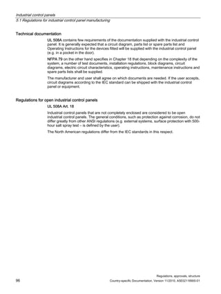
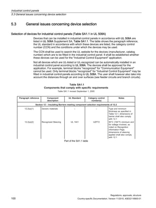
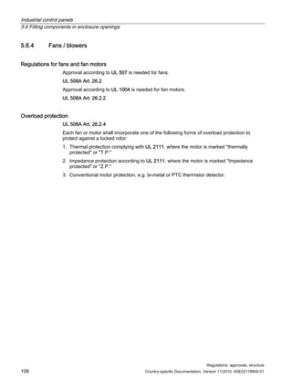
5.4 Regulations for noncurrent carrying metal parts in an industrial control
panel
All non-current carrying metal parts shall be conductively connected to one another if there is
the risk of them becoming energized for reasons such as a breakdown of insulation or loose
wiring connections and if they could thereby produce a dangerous situation. UL 508A Art. 14.
If command devices (pushbuttons, indicator lights) are fitted on doors on which devices with
voltages of more than 30 Vrms are installed, these shall be connected to the industrial
control panel using grounding wires. UL 508A Art. 66.3.4
For the minimum cross section of connecting wires, see 4.1.3 or UL 508A Table 15.1.
Exception: When using piano hinges as the door hinges, no extra grounding cables need
be used. Special, listed shims which penetrate the paint on metal parts are authorized as
grounding shims for screwed connections.
Checking continuity of connections between metal parts (Protective Bonding)
Two methods are used:
1. According to UL 508, [not UL 508A] Industrial Control Equipment, Art. 6.7:
Resistance measurement across two points of one connection: The resistance shall not
exceed 0.1 Ohm, measured using a resistance measuring instrument. If the results are
not acceptable, the resistance can also be calculated as follows:
Between the metal part in the enclosure and the ground terminal of the incoming, the
resistance is calculated by measuring the voltage drop, if there is a current of at least
20 A AC or DC, fed from the supply (not more than 12 V). The resistance is calculated by
dividing the voltage drop by the current.
2. According to NFPA 79 Art. 18/18.2:
Resistance measurement across two points of one connection: The resistance shall not
exceed 0.1 ohms.
A current of 10 A is provided, produced by an SELV (safety extra low voltage) current
source; the voltage drop is measured between the equipment ground terminal and
specified points on the industrial control panel; the voltage drop shall not exceed that
given in the table, compared with the cross section of the equipment grounding
conductor:
Maximum authorized voltage drop on grounding conductor at 10 A testing current
Minimum equipment grounding conductor Maximum authorized drop in voltage
18 AWG 3.3 V
16 AWG 2.6 V
14 AWG 1.9 V
12 AWG 1.7 V
10 AWG 1.4 V
8 AWG 1.0 V](https://image.slidesharecdn.com/guide-to-industrial-control-panels-230922040019-c60a1df7/85/Guide-to-Industrial-Control-Panels-pdf-101-320.jpg)
![Industrial control panels
5.7 Other built-in panel devices
Regulations, approvals, structure
108 Country-specific Documentation, Version 11/2010, A5E02118900-01
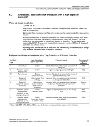
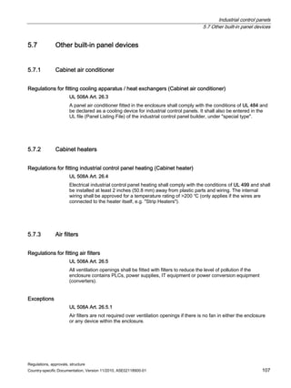
5.7.4 Thermal insulation in enclosures
Regulations for thermal insulation
If temperature-insulating or noise-insulating materials are fitted inside the enclosure, these
shall:
● Be supported by mechanical means (i.e. not adhesive).
● Be 1/2 inch (12 mm) or more away from uninsulated, live parts and 12 inches (305 mm)
away from arcing parts (use barriers). UL 508A Art. 26.6
Insulation material
● Materials for barriers: UL 508A Art. 12
● Are used between live parts and to ground to increase the distances through air and over
surface.
● The material may be in direct contact with live parts.
● The material does not serve to physically support the installation of devices and parts or
to maintain electrical spacing.
● For suitable materials and their minimum thicknesses, see Table 12.1 (e.g. Fish Paper
[electoral grade paper], Epoxy, Mica, Mylar, Silicone Rubber, etc.).
Materials that are used for the direct support of uninsulated, live parts:
UL 508A Art. 13. These materials are used for assembly and to maintain electrical spacing.
A number of these insulators are available: for example: as thread-bearing spacers (for
busbars and terminals) such as Johnny Balls, and glass-fibre reinforced plates
(e.g.Glastic).](https://image.slidesharecdn.com/guide-to-industrial-control-panels-230922040019-c60a1df7/85/Guide-to-Industrial-Control-Panels-pdf-108-320.jpg)
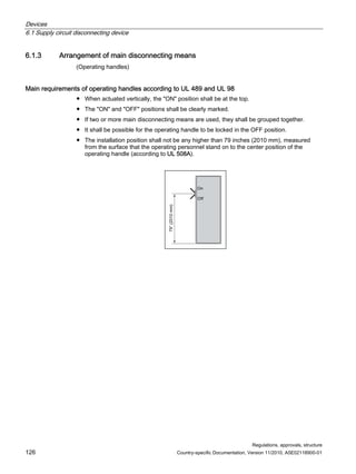
![Devices
6.1 Supply circuit disconnecting device
Regulations, approvals, structure
130 Country-specific Documentation, Version 11/2010, A5E02118900-01
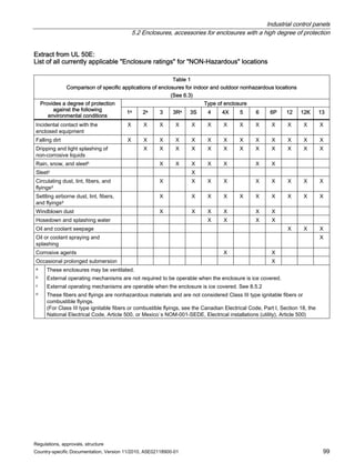
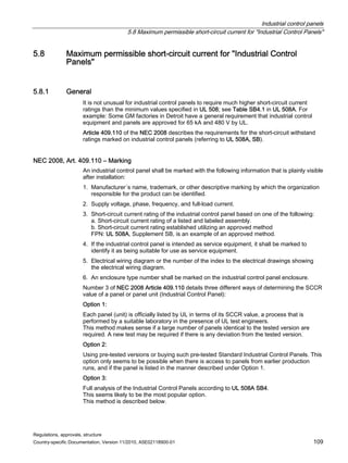
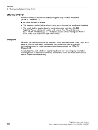
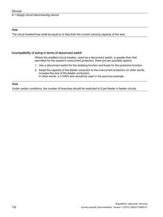
Disconnect switch (UL 98) with or without fuses
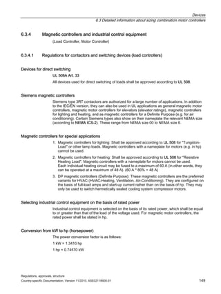
1. Calculate the full-load current (FLC) of each motor using Table 50.1 in UL 508A;
Exception: For special motors, use the FLA on the nameplate.
2. Multiply the total of all motor FLC values by 1.15 (115% of all rated motor currents).
3. Add the currents of all other loads.
4. Use the total of all the currents (virtual motor) calculated to establish the hp of the
disconnect switch according to Table 50.1 in UL 508A.
Example:
Main disconnecting means [A] = ∑ motors x 1.15 + ∑ loads
= (M1 + M2 + M3) x 1.15 + H1 + T1 + T2
= (7.6 + 4.8 + 27) x 1.15 + 6 + 12 + 1.6 = 64.9
Main disconnecting means [A] = 64,9
Note
According to UL 508A, Table 50.1. A motor carries 64.9 A at 480 V, which corresponds to 50 hp. In other words,
the main disconnecting means shall be selected for a minimum of 50 hp.
Circuit breaker (UL 489) only for isolating function; not for overload protection
1. Calculate the full-load current (FLC) of each motor using Table 50.1 in UL 508A
(attached); Exception: For special motors, use the FLC on the nameplate.
2. Add together the FLC of all motors and other loads.
3. Multiply the total of these currents by 1.25 (125% of all rated currents; circuit breakers
may only be loaded up to 80% of their rated current).
Example:
Main disconnecting means [A] = ∑ loads ≤ 80% current of circuit breaker
= (M1 + M2 + M3 + H1 + T1 + T2)
= (7.6 + 4.8 + 27 + 6 + 12+ 1.6) x 1.25
Main disconnecting means [A] = 73,8
Note
A standard circuit breaker should only be designed to operate at a maximum of 80%.](https://image.slidesharecdn.com/guide-to-industrial-control-panels-230922040019-c60a1df7/85/Guide-to-Industrial-Control-Panels-pdf-130-320.jpg)
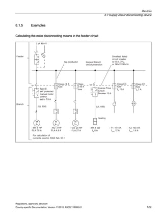
![Devices
6.1 Supply circuit disconnecting device
Regulations, approvals, structure
Country-specific Documentation, Version 11/2010, A5E02118900-01 131
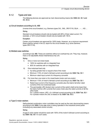
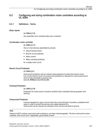
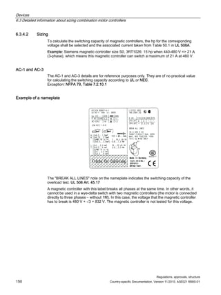
Sizing of disconnect switch with fuse (UL 248) or circuit breaker (UL 489) as overload protection for
feeder circuits
Calculating the circuit breaker or fuse size using the branch overload protection.
1. Select the largest branch circuit protection of all the branches (BCPD – Branch Circuit
Protective Device); fuse or circuit breaker.
2. Add together the rated currents of all loads.
3. Select a circuit breaker or fuses according to the load current calculated.
Example:
Protection [A] ≤ I largest protection + ∑ loads
Protection [A] ≤ 45 + 7,6 + 4,8 + 6 + 12 + 1,6 = 77,0
Calculating the size using the feeder and the wire cross section (in AWG)
For industrial control panels
according to UL 508A
Motor loads, select the rated currents from Table 50.1 in UL 508A
For industrial control panels according to NFPA 79
(or UL 508A Art. 66.5.6) (see above for areas of use):
Note: For ambient temperatures of more than 30 °C, see
temperature correction in NEC 2008 Table 310.16
Add together all loads for the resistor heaters and multiply the total
by 1.25 (125% of the rated currents).
Determine the rated current of the largest motor and multiply this
by 1.25 (125% of the FLA rated motor current).
Add together the rated currents
of all loads.
Add together the rated currents of all other motors and loads.
Select the wire size (AWG - American Wire Gauge)) according to the current calculated (or the next
largest wire) from Table 28.1 in UL 508A (Table 29.1 is being removed on March 1, 2007).
Example:
UL 508A: Feeder ∑ Loads
= M1 + M2 + M3 + H1 + T1 + T2
= 59 A
UL 508A, Table 28.1: 6 AWG (65 A)
NFPA 79: Feeder = ∑ heater loads x 1.25 + FLC of largest motor x 1.25 + M1 +
M2 + T1 + T2
= (6 x 1.25) + (27 x 1.25) + 7.6 + 12 + 1.6
= 67.25 A
UL 508A, Table 28.1: 4 AWG (85 A)](https://image.slidesharecdn.com/guide-to-industrial-control-panels-230922040019-c60a1df7/85/Guide-to-Industrial-Control-Panels-pdf-131-320.jpg)
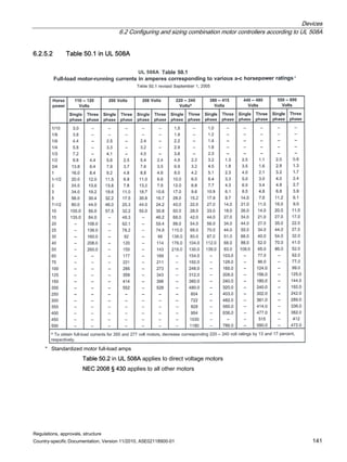
![Devices
6.2 Configuring and sizing combination motor controllers according to UL 508A
Regulations, approvals, structure
Country-specific Documentation, Version 11/2010, A5E02118900-01 139
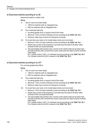
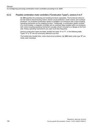
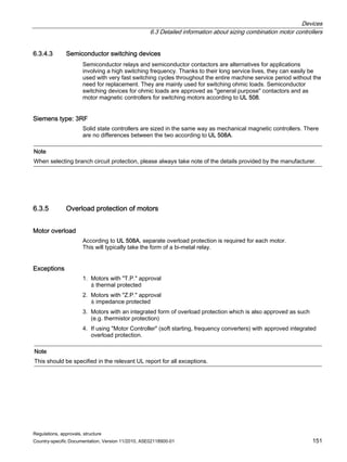
6.2.5 Basis for the dimensioning of combination motor controllers according to UL 508A
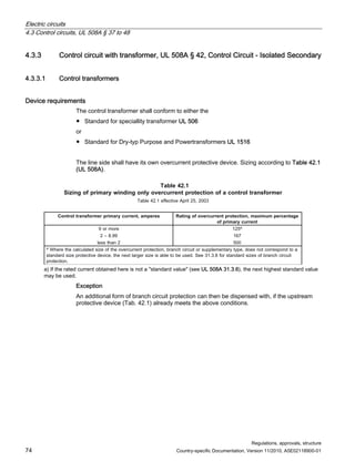
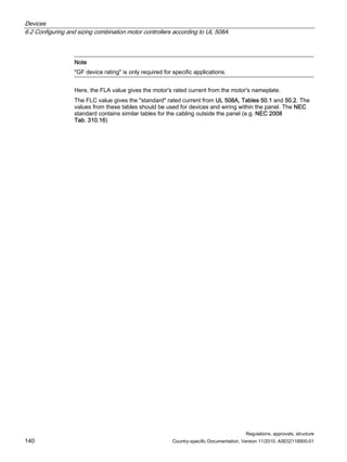
6.2.5.1 Information on different motor currents
Full load current (FLC) and Full load ampere (FLA)
FLC ≙ full-load current according to the standard
FLA ≙ full-load ampere according to the nameplate
According to UL 508A, only the FLC should be used for sizing combination motor controllers.
In this context, it is advisable to consult Table 50.1 (UL 508A). NEC 2008 § 310 applies
when sizing cables outside the panel.
The only exception relates to motor overload protection – in this case, the FLA on the
nameplate should be used instead.
The following image should make this clear:
)/$
8VHRI)/DQG)/$
)/
1DPHSODWH
$OH[0RWRUR
+3
9ROWV
RGH
530
)UDPH
*
3+
)/$
'HVLJQ
'HJUHH
ULVH
(
r
KS $
9ROWV
9ROWV
9ROWV
8/$7DE
RGHU1(
)HHGHU6*)GHYLFHUDWLQJ
)HHGHUFRQGXFWRUVL]H
%UDQFKFLUFXLW6*)GHYLFHUDWLQJ
%UDQFKFLUFXLWFRQGXFWRUVL]H
'LVFRQQHWFWLQJPHDQVUDWLQJ
RQWUROOHUUDWLQJ
2YHUORDGUDWLQJ
Source: Electrical Inspection Manual (Fig. 7.4)](https://image.slidesharecdn.com/guide-to-industrial-control-panels-230922040019-c60a1df7/85/Guide-to-Industrial-Control-Panels-pdf-139-320.jpg)
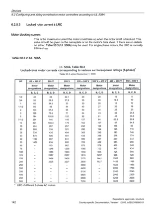
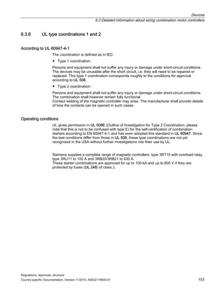
![Devices
6.3 Detailed information about sizing combination motor controllers
Regulations, approvals, structure
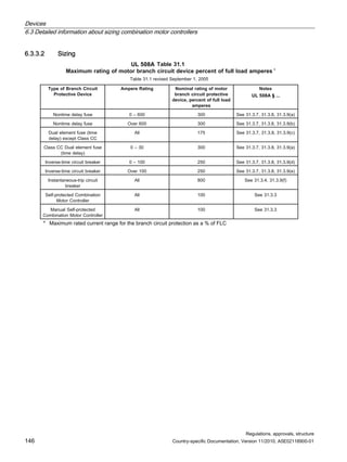
156 Country-specific Documentation, Version 11/2010, A5E02118900-01
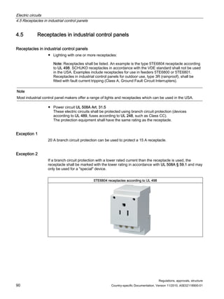
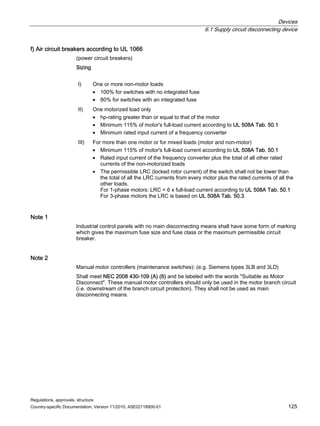
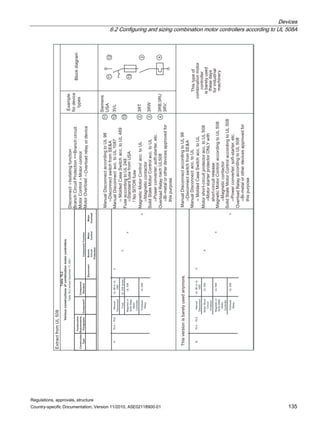
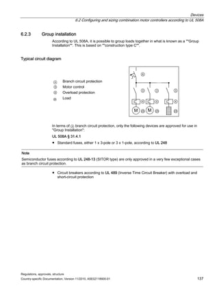
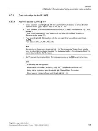
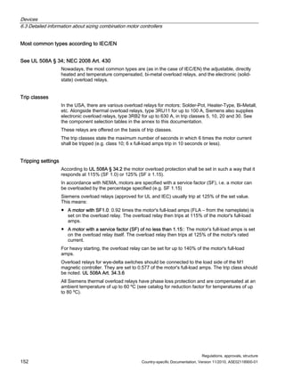
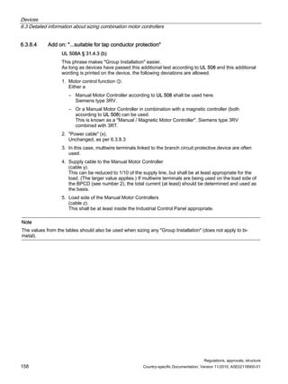
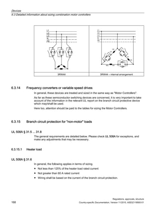
6.3.8 Group installation
UL 508A § 31.4
UL 508A takes Group Installation to mean:
● 2 or more motors
● 1 motor and other loads
This kind of group can be protected by a single Branch Circuit Protective device (≙ branch
circuit protection).
6.3.8.1 Approved devices
● Branch Circuit Fuse according to UL 248
standard branch fuse
● Inverse Time-Circuit Breakeraccording to UL 248
type 3VL, 3RV17/18, 5SJ4... HG circuit breakers
6.3.8.2 Structure
Based on the approved devices (see above), only version A and C combination motor
controllers can be used.
The following example is based on version C.
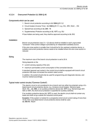
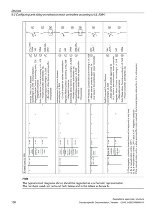
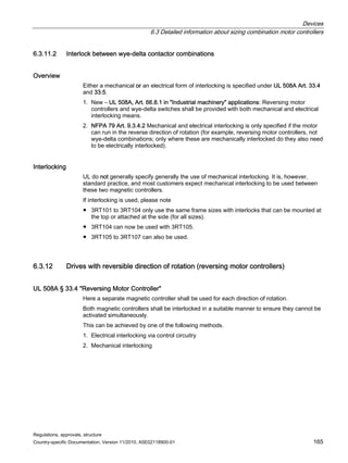
Typical circuit diagram
A Branch circuit protection
③ Motor control
④ Overload protection
x Supply line to the motor group
y Supply line to the Manual Motor Controller
z Load side of the Manual Motor Controllers
(cables)
0 0
$
[
]
]
]
]](https://image.slidesharecdn.com/guide-to-industrial-control-panels-230922040019-c60a1df7/85/Guide-to-Industrial-Control-Panels-pdf-156-320.jpg)
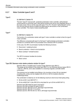
![Devices
6.3 Detailed information about sizing combination motor controllers
Regulations, approvals, structure
162 Country-specific Documentation, Version 11/2010, A5E02118900-01
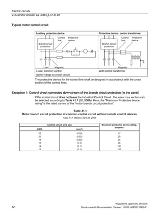
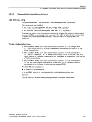
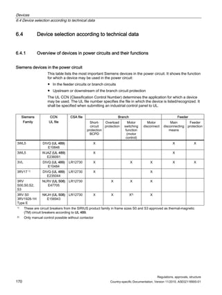
6.3.10 Example of combination motor controllers with SIRIUS 3RV motor starter
protectors
Overview of the numerous applications of the Siemens type 3RV motor starter protector
6HQVRU
59IRU
IXVH
PRQLWRULQJ EORZQ
IXVHLQGLFDWRU
59XVHGDV
PRWRU
GLVFRQQHFW
%UDQFK
59LQJURXSLQVWDOODWLRQ
DSSOLFDWLRQV
59LQ
FRQWUROSRZHU
WUDQVIRUPHU
DSSOLFDWLRQV
59LQFRPELQDWLRQPRWRU
FRQWUROOHUDSSOLFDWLRQV
PDQXDOFRPELQDWLRQ
FRQWUROOHUZLWKRXWFRQWDFWRU
)HHGHURU
%UDQFK
RPSDULVRQ
RIVPEROV
59DVFLUFXLW
EUHDNHULQ
GLVWULEXWRUVDQG
IHHGHUV
DOOVL]HV DOOVL]HV DOOVL]HV
EXWHVSHFLDOO
59
QRWDOOVL]HV
SHUPLVVLEOHXSWR$
8/
1($UW
RQOIRUPRWRUORDGV
1RWIRU
KLJKFXUUHQW
WUDQVIRUPHUV
8/
8/
7SH(
7SH)
7UDQVIRUPHU
PRWRU
'LVFRQ
QHFWLQJ
VZLWFK
2YHUORDG
UHOD
RQWDFWRU
LUFXLW
EUHDNHU
IXVH
6ZLWFKGLVFRQQHFWRU
LVWKHIXQFWLRQRIWKH59
$16, ,((1
59B%' 5959
ELV$
8/)LOH
(
9RO6HF
ಱ6XLWDEOHIRU
0RWRU'LVFRQQHFWಯ
8/
1($UW
8/
ಱ/LVWHG,QYHUVH7LPH
LUFXLW%UHDNHUಯ
ಱ6XLWDEOHIRUWDS
FRQGXFWRUSURWHFWLRQಯ
① The auxiliary switch 3RV1901-1E or -1A should be
ordered separately
⑦ 125% power capacity of the motor's full load
② Fuse or circuit breaker ⑧ 125% power capacity of the load
③ Current = 250 % of largest FLC + Σ of all motors ⑨ Magnetic controller is optional
④ Current = 175 % of largest FLC + Σ of all motors ⑩ Small terminal spacing (distances through air and over
surfaces):
⑤ Large terminal spacing (distances through air and over
surfaces):
⑪ Suitable, for tap conductor protection in group
application
⑥ Magnetic controller optional for Manual Combination
Controller
⑫ Tap rule applicable](https://image.slidesharecdn.com/guide-to-industrial-control-panels-230922040019-c60a1df7/85/Guide-to-Industrial-Control-Panels-pdf-162-320.jpg)
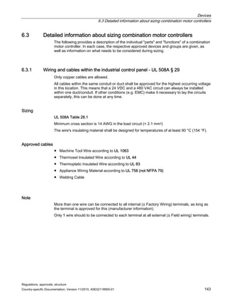
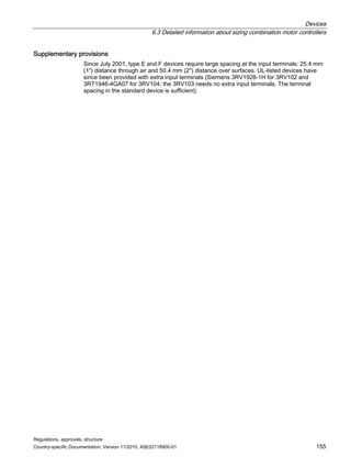
![Devices
6.3 Detailed information about sizing combination motor controllers
Regulations, approvals, structure
164 Country-specific Documentation, Version 11/2010, A5E02118900-01
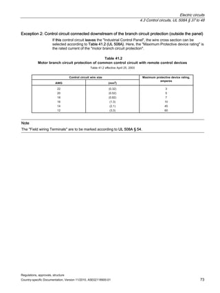
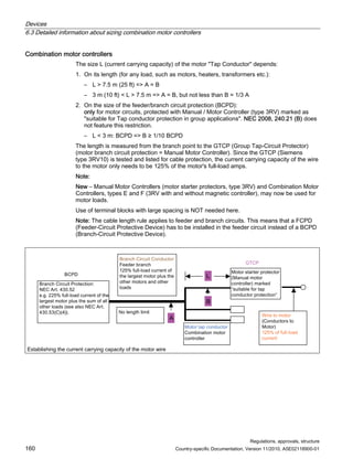
6.3.11.1 Magnetic controller sizing
0RWRU
6
6
0
0
0
0
0
0
6
0
0
6 ;
; ; ;
;
0
0
6
6
23(1,58,775$16,7,21
217$7256(48(1(
217$
725
67$57 75$16,
7,21
581
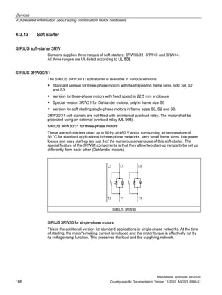
7DEOH
RQWDFWRUVL]LQJIRUZHGHOWDFRQWUROOHU
7DEOHHIIHFWLYH$SULO
RQWDFWRUGHVLJQDWLRQ
5HTXLUHGFRQWDFWRUDPSHUHUDWLQJ
PDNHFXUUHQW/5$ EUHDNFXUUHQW)/$
PXOWLSOLHGEPRWRU/5$
PXOWLSOLHGEPRWRU/5$
1RFXUUHQW
D
PXOWLSOLHGEPRWRU)/$
PXOWLSOLHGEPRWRU)/$
PXOWLSOLHGEPRWRU/5$
D
D
5DWLQJRIFRQWDFWRUVKDOOEHGHWHUPLQHGEDVHGRQWKHLPSHGDQFHSURYLGHG
According to this table, the power supply, delta and wye magnetic controllers should be
sized such that the values specified above are below the values tested in UL 508. The
corresponding magnetic controllers for power ratings of 5-300 hp at 230, 460 and 575 V are
given in the Annex under Devices.
Siemens solution
Siemens supplies ready wired wye-delta combinations (without overload relay) for up to 95 A
of motor current. Furthermore, the individual Siemens devices that you can fit yourself are
detailed in a table.
A couple of technical notes:
● The start-up current in wye is 1/3 of the start-up current in delta
● Phase current divided by power supply and delta magnetic controller is 0.577 of the rated
motor current.
● The wye magnetic controller is 0.33 of the rated motor current.
New: The 1S wye magnetic controller does not have to be taken into account when
establishing the short-circuit current rating. UL 508A, Art. SB4.2.1](https://image.slidesharecdn.com/guide-to-industrial-control-panels-230922040019-c60a1df7/85/Guide-to-Industrial-Control-Panels-pdf-164-320.jpg)
![Devices
6.3 Detailed information about sizing combination motor controllers
Regulations, approvals, structure
Country-specific Documentation, Version 11/2010, A5E02118900-01 169
6.3.15.2 General appliance protection (appliance load)
UL 508A § 31.7
● Single appliance, non-motor-operated:
– According to the technical documentation for the appliance
– Not more than 20 A for appliances rated higher than 13.3 A where the appliance
documentation contains no relevant specific details
– 150% for appliances rated higher than 13.3 A where the appliance documentation
contains no relevant specific details.
Exception:
An appliance provided with a power supply cord is not obliged to comply with this
requirement as the receptacle used for connection is itself protected.
● Single motor-operated appliance
– According to the technical documentation for the appliance
– Or the requirements relating to combination motor controllers
– Or the requirements relating to receptacles
6.3.16 Determining the full-load ampacity of transformers, heater loads and capacitor
loads
UL 508A Art. 50.6
If transformers (rating in VA), heater loads (rating in W) or capacitor loads (rating in VAR) are
used, the full-load amps are calculated as follows:
Single-phase: Current [A] = (rating in VA, W or VAR) ∕ (rated voltage [V])
Three-phase: Current [A] = (rating in VA, W or VAR) ∕√3 × (rated voltage [V])](https://image.slidesharecdn.com/guide-to-industrial-control-panels-230922040019-c60a1df7/85/Guide-to-Industrial-Control-Panels-pdf-169-320.jpg)
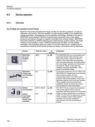
![Devices
6.4 Device selection according to technical data
Regulations, approvals, structure
Country-specific Documentation, Version 11/2010, A5E02118900-01 173
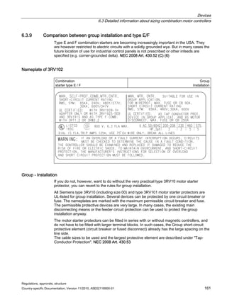
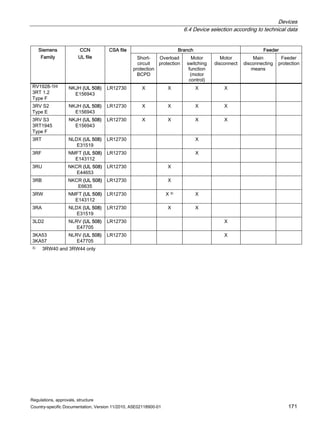
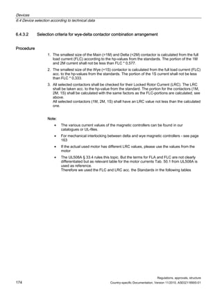
6.4.3 Devices for combination motor controllers
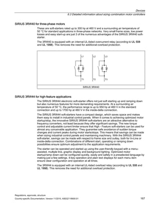
6.4.3.1 Tables for selecting across-the-line magnetic controllers
Maximum Current Maximum Horsepower Ratings
Single Phase Three Phase hp Ratings
SIRIUS
Frame Sizes
Inductive
AC3
Amperage
Resistive
AC1
Amperage
115 V
[hp]
230 V
[hp]
200 V
[hp]
230 V
[hp]
460 V
[hp]
575 V
[hp]
3RT1015 7 18 0.25 0.75 1.5 2 3 5
3RT1016 9 22 0.33 1 2 3 5 7.5
3RT1017 12 22 0.5 2 3 3 7.5 10
3RT1023
3RT1024
3RT1025
3RT1026
9
12
17
25
40
40
40
40
0.33
0.5
0.5
1
1
2
2
3
2
3
5
7.5
3
3
5
7.5
5
7.5
10
15
7.5
10
15
20
3RT1033
3RT1034
3RT1035
3RT1036
28
32
40
50
40
50
60
60
2
2
3
3
5
5
7.5
10
7.5
10
10
15
10
10
15
15
20
25
30
40
25
30
40
50
3RT1044
3RT1045
3RT1046
65
80
95
100
120
120
5
7.5
10
15
15
20
25
30
25
30
30
50
60
75
60
75
100
3RT1054
3RT1055
3RT1056
115
150
185
160
185
215
-
-
-
25
30
30
40
50
60
50
60
75
100
125
150
125
150
200
3RT1064
3RT1065
3RT1066
225
265
300
275
330
330
-
-
-
-
-
-
60
75
100
75
100
125
150
200
250
200
250
300
3RT1075
3RT1076
400
500
430
610
-
-
-
-
125
150
150
200
300
400
400
500
3TF68
3TF69
630
820
700
910
-
-
-
-
200
290
250
300
500
700
650
860](https://image.slidesharecdn.com/guide-to-industrial-control-panels-230922040019-c60a1df7/85/Guide-to-Industrial-Control-Panels-pdf-173-320.jpg)
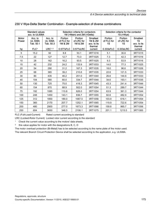
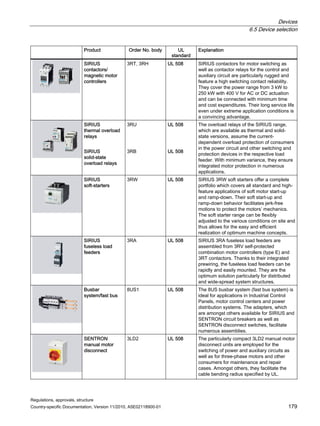

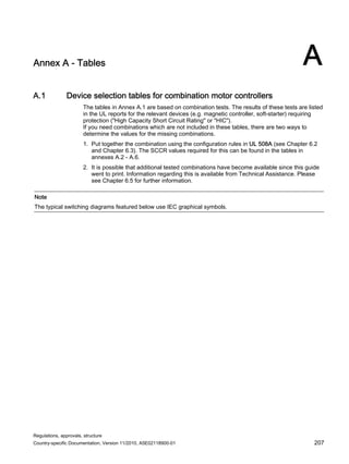
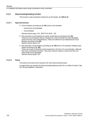
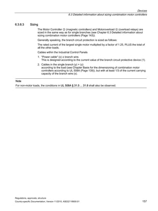
![Annex A - Tables
A.1 Device selection tables for combination motor controllers
Regulations, approvals, structure
Country-specific Documentation, Version 11/2010, A5E02118900-01 209
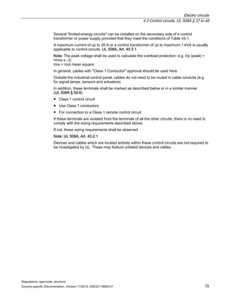
A.1.1 240 VAC corner grounded delta
Table A- 1 240 V – Type F
240 V corner grounded Delta - Self-Protected Manual / Magnetic Motor Control - Construction Type F
Rated
motor
output
[hp]
Standard
motor current
(according to
the standard)
FLC [A]
Typical
motor
amps
FLA [A]
Motor starter
protector
(Self
Protected)
Type E
terminal block
Magnetic
controller
(Motor
Control)
SCCR
[kA]
Internal wire
cross section
for Cu
(75 °C)
[AWG]
X1 *) X2 *) X3 *) (5) *) (5.1) *) (3) *) X4 *) X5 *)
0.5 2.2 1.7 3RV1021-
1BA..
3RV1928-1H 3RT1023 65 14
0.75 3.2 2.34 3RV1021-
1CA..
3RV1928-1H 3RT1023 65 14
1 4.2 3.1 3RV1021-
1DA..
3RV1928-1H 3RT1023 65 14
1.5 6.0 4.3 3RV1021-
1FA..
3RV1928-1H 3RT1023 65 14
2 6.8 5.8 3RV1021-
1GA..
3RV1928-1H 3RT1023 65 14
3 9.6 8.3 3RV1021-
1JA..
3RV1928-1H 3RT1023 65 14
5 15.2 13.2 3RV1021-
4AA..
3RV1928-1H 3RT1025 65 12
7.5 22.0 19.4 3RV1021-
4BA..
3RV1928-1H 3RT1026 65 10
10 28.0 25.2 3RV1031-
4EA..
--- a) 3RT1033 65 10
15 42.0 38.2 3RV1031-
4FA..
--- a) 3RT1035 65 8
20 54 50.6 3RV1041-
4JA..
--- a) 3RT1044 65 6
25 68 62.6 3RV1041-
4KA..
3RT1946-
4GA07
3RT1044 65 4
30 80 72.8 3RV1041-
4KA..
3RT1946-
4GA07
3RT1045 65 4
x
M
40 104 94.5 3RV1041-
4MA..
3RT1946-
4GA07
3RT1046 65 2
a) No add-on terminal is required for this type.
*) For information, see Device selection tables for combination motor controllers (Page 207)](https://image.slidesharecdn.com/guide-to-industrial-control-panels-230922040019-c60a1df7/85/Guide-to-Industrial-Control-Panels-pdf-209-320.jpg)
![Annex A - Tables
A.1 Device selection tables for combination motor controllers
Regulations, approvals, structure
210 Country-specific Documentation, Version 11/2010, A5E02118900-01
Table A- 2 240 V – Type E
240 V corner grounded Delta - Self-Protected Manual Motor Control - Construction Type E
Rated
motor
output
[hp]
Standard
motor current
(according to
the standard)
FLC [A]
Typical
motor amps
FLA [A]
Motor starter
protector
(Self Protected)
Type E terminal
block
SCCR
[kA]
Internal wire
cross section
for Cu
(75 °C)
[AWG]
X1 *) X2 *) X3 *) (5) *) (5.1) *) X4 *) X5 *)
0.5 2.2 1.7 3RV1021-1BA.. 3RV1928-1H 65 14
0.75 3.2 2.34 3RV1021-1CA.. 3RV1928-1H 65 14
1 4.2 3.1 3RV1021-1DA.. 3RV1928-1H 65 14
1.5 6.0 4.3 3RV1021-1FA.. 3RV1928-1H 65 14
2 6.8 5.8 3RV1021-1GA.. 3RV1928-1H 65 14
3 9.6 8.3 3RV1021-1JA.. 3RV1928-1H 65 14
5 15.2 13.2 3RV1021-4AA.. 3RV1928-1H 65 12
7.5 22.0 19.4 3RV1021-4BA.. 3RV1928-1H 65 10
10 28.0 25.2 3RV1031-4EA.. --- a) 65 10
15 28.0 38.2 3RV1031-4FA.. --- a) 65 8
20 54 50.6 3RV1041-4JA.. --- a) 65 6
25 68 62.6 3RV1041-4KA.. 3RT1946-4GA07 65 4
30 80 72.8 3RV1041-4KA.. 3RT1946-4GA07 65 4
x
M
40 104 94.5 3RV1041-4MA.. 3RT1946-4GA07 65 2
a) 3RV103 already has large distances through air and over surfaces.
*) For information, see Device selection tables for combination motor controllers (Page 207)](https://image.slidesharecdn.com/guide-to-industrial-control-panels-230922040019-c60a1df7/85/Guide-to-Industrial-Control-Panels-pdf-210-320.jpg)
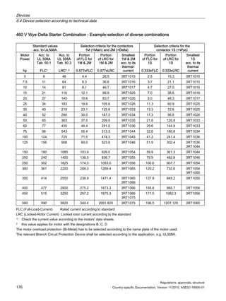
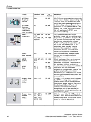
![Annex A - Tables
A.1 Device selection tables for combination motor controllers
Regulations, approvals, structure
Country-specific Documentation, Version 11/2010, A5E02118900-01 211
Table A- 3 240 V – Magnetic Motor Control
240 V corner grounded Delta - Magnetic Motor Control - Construction Type C
Rated
motor
output
[hp]
Standard motor
current
(according to
the standard)
FLC [A]
Typical
motor
amps
FLA [A]
MCCB Magnetic
controller
(Motor
Control)
Overload
(Overload
Relay)
SCCR
[kA]
Internal wire
cross section
for Cu
(75 °C)
[AWG]
X1 *) X2 *) X3 *) (1) *) (3) *) (4) *) b’) X4 *) X5 *)
0.5 2.2 1.7 3RV1721-
1ED10 xx)
3RT1023 3RB2906-
2BG1
50
xx)
14
0.75 3.2 2.34 3RV1721-
1GD10 xx)
3RT1023 3RB2906-
2BG1
50
xx)
14
1 4.2 3.1 3RV1721-
1HD10 xx)
3RT1023 3RB2906-
2DG1
50
xx)
14
1.5 6.0 4.3 3RV1721-
4KD10 xx)
3RT1023 3RB2906-
2DG1
50
xx)
14
2 6.8 5.8 3RV1721-
4AD10 xx)
3RT1023 3RB2906-
2DG1
50
xx)
14
3 9.6 8.3 3RV1721-
4BD10 xx)
3RT1023 3RB2906-
2DG1
50
xx)
14
5 15.2 13.2 3RV1721-
4CD10 xx)
3RT1025 3RB2906-
2DG1
50
xx)
12
7.5 22.0 19.4 3RV1742-
5HD10
3RT1026 3RB2906-
2DG1
65 10
10 28.0 25.2 3RV1742-
5JD10
3RT1033 3RB2906-
2JG1
65 10
15 42.0 38.2 3RV1742-
5LD10
3RT1035 3RB2906-
2JG1
65 8
20 54 50.6 3RV1742-
5PD10
3RT1044 3RB2906-
2JG1
65 6
25 68 62.6 3VL1191-
1KM30-….
3RT1044 3RB2906-
2JG1
65 4
x
M
30 80 72.8 3VL1112-
1KM30-….
3RT1045 3RB2906-
2JG1
65 4
b) Can only be used with the 3RB22 or 3RB23 evaluation modules and 3RB29 87-2 connecting cables
*) For information, see Device selection tables for combination motor controllers (Page 207)
xx) Alternatively, 3RV1742-… can also be used here. This allows 65 kA SCCR to be reached.](https://image.slidesharecdn.com/guide-to-industrial-control-panels-230922040019-c60a1df7/85/Guide-to-Industrial-Control-Panels-pdf-211-320.jpg)
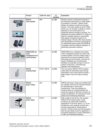
![Annex A - Tables
A.1 Device selection tables for combination motor controllers
Regulations, approvals, structure
212 Country-specific Documentation, Version 11/2010, A5E02118900-01
Table A- 4 240 V – Manual/Magnetic Motor Control
240 V corner grounded Delta - Manual / Magnetic Motor Control - Construction Type C
Rated
motor
output
[hp]
Standard
motor current
(according to
the standard)
FLC [A]
Typical
motor
amps
FLA [A]
MCCB Magnetic
controller **)
(Motor
Control)
Overload
(Overload
Relay)
xxx)
SCCR
[kA]
Internal wire
cross section
for Cu (75 °C)
[AWG]
X1 *) X2 *) X3 *) (1) *) (3) *) (4) *) X4 *) X5 *)
0.5 2.2 1.7 3RV1721
-1ED10
3RT1013 3RV1011-
1BA..
50 14
0.75 3.2 2.34 3RV1721
-1GD10
3RT1013 3RV1011-
1CA..
50 14
1 4.2 3.1 3RV1721
-1HD10
3RT1013 3RV1011-
1EA..
50 14
1.5 6.0 4.3 3RV1721
-1JD10
3RT1013 3RV1011-
1FA..
50 14
2 6.8 5.8 3RV1721
-1KD10
3RT1013 3RV1011-
1GA..
50 14
3 9.6 8.3 3RV1721
-4AD10
3RT1013 3RV1011-
1JA..
50 14
5 15.2 13.2 3RV1721
-4CD10
3RT1025 3RV1021-
4AA..
50 12
7.5 22.0 19.4 3RV1742
-5FD10
3RT1026 3RV1021-
4CA..
65 10
10 28.0 25.2 3RV1742
-5JD10
3RT1033 3RV1031-
4EA..
65 10
15 42.0 38.2 3RV1742
-5PD10
3RT1035 3RV1031-
4FA..
65 8
20 54 50.6 3RV1742
-5PD10
3RT1044 3RV1041-
4JA..
65 6
25 68 62.6 3VL1110
-1KN30-
….
3RT1044 3RV1041-
4KA..
65 4
x
optional
M
30 80 72.8 3VL1120
-1KN30-
….
3RT1045 3RV1041-
4LA..
65 4
*) For information, see Device selection tables for combination motor controllers (Page 207)
**) No magnetic controller is required for this version of the motor starter.
xxx) This 3RV (4) is approved both as a Manual Motor Controller and as motor overload protection.
If a magnetic controller is used, it will be a Manual/Magnetic Motor Controller.
If no magnetic controller is used, it will be a Manual Motor Controller.](https://image.slidesharecdn.com/guide-to-industrial-control-panels-230922040019-c60a1df7/85/Guide-to-Industrial-Control-Panels-pdf-212-320.jpg)
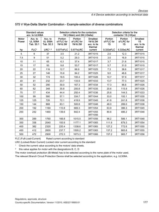
![Annex A - Tables
A.1 Device selection tables for combination motor controllers
Regulations, approvals, structure
Country-specific Documentation, Version 11/2010, A5E02118900-01 213
A.1.2 480/277 VAC, solidly grounded wye
Table A- 5 480/277 V – Type F
480 / 277 V solidly grounded Wye - Self-Protected Manual / Magnetic Motor Control Construction Type F
Motor
rated
output
[hp]
Standard
motor current
(according to
the standard)
FLC [A]
Typical
motor amps
FLA [A]
Motor
starter
protector
(Self
Protected)
Type E
terminal
block
Magnetic
controller
(Motor
Control)
SCCR
[kA]
Internal wire
cross section
for Cu
(75 °C)
[AWG]
X1 *) X2 *) X3 *) (5) *) (5.1) *) (3) *) X4 *) X5 *)
0.5 1.1 0.67 3RV1021-
0HA..
3RV1928-
1H
3RT1023 65 14
0.75 1.6 0.93 3RV1021-
0JA..
3RV1928-
1H
3RT1023 65 14
1 2.1 1.2 3RV1021-
0KA..
3RV1928-
1H
3RT1023 65 14
1.5 3 1.7 3RV1021-
1BA..
3RV1928-
1H
3RT1023 65 14
2 3.4 2.3 3RV1021-
1CA..
3RV1928-
1H
3RT1023 65 14
3 4.8 3.3 3RV1021-
1EA..
3RV1928-
1H
3RT1023 65 14
5 7.6 5.3 3RV1021-
1GA..
3RV1928-
1H
3RT1023 65 14
7.5 11 7.7 3RV1021-
1HA..
3RV1928-
1H
3RT1024 65 14
10 14 10.1 3RV1021-
1JA..
3RV1928-
1H
3RT1025 65 14
15 21 15.2 3RV1021-
4AA..
3RV1928-
1H
3RT1026 65 10
20 27 20.2 3RV1031-
4DA..
--- a) 3RT1033 65 10
25 34 25 3RV1031-
4EH..
--- a) 3RT1034 65 8
30 40 29.2 3RV1031-
4EA..
--- a) 3RT1035 65 8
40 52 39.2 3RV1041-
4FA..
3RT1946-
4GA07
3RT1036 65 6
50 65 48.4 3RV1031-
4DA..
3RT1946-
4GA07
3RT1044 65 6
60 77 57.2 3RV1041-
4JA..
3RT1946-
4GA07
3RT1045 65 4
x
M
75 96 71.2 3RV1041-
4KA..
3RT1946-
4GA07
3RT1046 65 3
a) No add-on terminal is required for this type.
*) For information, see Device selection tables for combination motor controllers (Page 207)](https://image.slidesharecdn.com/guide-to-industrial-control-panels-230922040019-c60a1df7/85/Guide-to-Industrial-Control-Panels-pdf-213-320.jpg)
![Annex A - Tables
A.1 Device selection tables for combination motor controllers
Regulations, approvals, structure
214 Country-specific Documentation, Version 11/2010, A5E02118900-01
Table A- 6 480/277 V – Type E
480 / 277V solidly grounded Wye - Self-Protected Manual Motor Control - Construction Type E
Rated
motor
output
[hp]
Standard motor
current
(according to
the standard)
FLC [A]
Typical
motor amps
FLA [A]
Motor starter
protector (Self
Protected)
Type E terminal
block
SCCR
[kA]
Internal wire
cross section
for Cu
(75 °C)
[AWG]
X1 *) X2 *) X3 *) (5) *) (5.1) *) X4 *) X5 *)
0.5 1.1 0.67 3RV1021-0HA.. 3RV1928-1H 65 14
0.75 1.6 0.93 3RV1021-0JA.. 3RV1928-1H 65 14
1 2.1 1.2 3RV1021-0KA.. 3RV1928-1H 65 14
1.5 3 1.7 3RV1021-1BA.. 3RV1928-1H 65 14
2 3.4 2.3 3RV1021-1CA.. 3RV1928-1H 65 14
3 4.8 3.3 3RV1021-1EA.. 3RV1928-1H 65 14
5 7.6 5.3 3RV1021-1GA.. 3RV1928-1H 65 14
7.5 11 7.7 3RV1021-1HA.. 3RV1928-1H 65 14
10 14 10.1 3RV1021-1JA.. 3RV1928-1H 65 14
15 21 15.2 3RV1021-4AA.. 3RV1928-1H 65 10
20 27 20.2 3RV1031-4DA.. --- a) 65 10
25 34 25 3RV1031-4EA.. --- a) 65 8
30 40 29.2 3RV1031-4EA.. --- a) 65 8
40 52 39.2 3RV1041-4FA.. 3RT1946-
4GA07
65 6
50 65 48.4 3RV1041-4FA.. 3RT1946-
4GA07
65 6
60 77 57.2 3RV1041-4JA.. 3RT1946-
4GA07
65 4
75 96 71.2 3RV1041-4KA.. 3RT1946-
4GA07
65 3
x
M
100 124 91.85 3RV1041-4LA.. 3RT1946-
4GA07
65 1
a) No add-on terminal is required for this type.
*) For information, see Device selection tables for combination motor controllers (Page 207)](https://image.slidesharecdn.com/guide-to-industrial-control-panels-230922040019-c60a1df7/85/Guide-to-Industrial-Control-Panels-pdf-214-320.jpg)
![Annex A - Tables
A.1 Device selection tables for combination motor controllers
Regulations, approvals, structure
Country-specific Documentation, Version 11/2010, A5E02118900-01 215
Table A- 7 480/277 V – Magnetic Motor Control
480 / 277V solidly grounded Wye - Magnetic Motor Control - Construction Type C
Rated
motor
output
[hp]
Standard
motor current
(according to
the standard)
FLC [A]
Typical
motor
amps
FLA [A]
MCCB Magnetic
controller
(Motor
Control)
Overload
(Overload
Relay)
SCCR
[kA]
Internal wire
cross section
for Cu
(75 °C)
[AWG]
X1 *) X2 *) X3 *) (1) *) (3) *) (4) *) X4 *) X5 *)
0.5 1.10 0.67 3RV1721-
1BD10
3RT1023 3RB2906-
2BG1b)
50 14
0.75 1.60 0.93 3RV1721-
1DD10
3RT1023 3RB2906-
2BG1b)
50 14
1 2.10 1.2 3RV1721-
1ED10
3RT1023 3RB2906-
2BG1b)
50 14
1.5 3.00 1.7 3RV1721-
1FD10
3RT1023 3RB2906-
2BG1b)
50 14
2 3.40 2.3 3RV1721-
1GD10
3RT1023 3RB2906-
2BG1b)
50 14
3 4.80 3.3 3RV1721-
1HD10
3RT1023 3RB2906-
2JG1b)
50 14
5 7.60 5.3 3RV1721-
4AD10
3RT1023 3RB2906-
2JG1b)
50 14
7.5 11.00 7.7 3RV1721-
4BD10
3RT1024 3RB2906-
2JG1b)
50 14
10 14.00 10.1 3RV1721-
4CD10
3RT1025 3RB2906-
2JG1b)
50 14
15 21.00 15.2 3RV1742-
5FD10
3RT1026 3RB2906-
2JG1b)
65 10
20 27.00 20.2 3RV1742-
5HD10
3RT1033 3RB2906-
2JG1b)
65 10
25 34.00 25 3RV1742-
5JD10
3RT1034 3RB2906-
2JG1b)
65 8
30 40.00 29.2 3RV1742-
5LD10
3RT1035 3RB2906-
2JG1b)
65 8
40 52.00 39.2 3RV1742-
5PD10
3RT1036 3RB2906-
2JG1b)
65 6
x
M
50 65.00 48.4 3VL3110-
2KN30-….
3RT1044 3RB2906-
2JG1b)
65 6
b) Can only be used with the 3RB22 or 3RB23 evaluation modules and 3RB29 87-2 connecting cables.
c) The standard values are currently the only values for branches with this level of power (hp).
*) For information, see Device selection tables for combination motor controllers (Page 207)
Table continued on next page](https://image.slidesharecdn.com/guide-to-industrial-control-panels-230922040019-c60a1df7/85/Guide-to-Industrial-Control-Panels-pdf-215-320.jpg)
![Annex A - Tables
A.1 Device selection tables for combination motor controllers
Regulations, approvals, structure
216 Country-specific Documentation, Version 11/2010, A5E02118900-01
Continued from previous page
480 / 277V solidly grounded Wye - Magnetic Motor Control - Construction Type C
Rated
motor
output
[hp]
Standard
motor current
(according to
the standard)
FLC [A]
Typical
motor
amps
FLA [A]
MCCB Magnetic
controller
(Motor
Control)
Overload
(Overload
Relay)
SCCR
[kA]
Internal wire
cross section
for Cu
(75 °C)
[AWG]
X1 *) X2 *) X3 *) (1) *) (3) *) (4) *) X4 *) X5 *)
60 77.00 57.2 3VL3115-
2KN30-….
3RT1045 3RB2906-
2JG1b)
65 4
75 96.00 71.2 3VL3115-
2KN30-….
3RT1046 3RB2906-
2JG1b)
65 3
100 124.00 91.9 3VL3120-
1KN30-….
3RT1054 3RB2906-
2JG1b)
10c) 1
125 156.00 115.6 3VL3125-
1KN30-….
3RT1055 3RB2956-
2T.2b)
10c) 2/0
150 180.00 133.3 3VL4125-
1KN30-….
3RT1056 3RB2956-
2T.2b)
10c) 3/0
200 240.00 177.8 3VL4135-
1KN30-….
3RT1.65 3RB2956-
2T.2b)
10c) 250 kcmil
250 302.00 223.7 3VL4140-
1KN30-….
3RT1.66 3RB2966-
2WH2b)
18c) 350 kcmil
300 361.00 267.4 3VL4550-
1KN30-….
3RT1.75 3RB2966-
2WH2b)
18c) 500 kcmil
350 414.00 306.7 3VL4560-
1KN30-….
3RT1.76 3RB2966-
2WH2b)
18c) 600 kcmil
400 477.00 353.3 3VL6160-
1KN30-….
3RT1.76 3RB2966-
2WH2b)
18c) 800 kcmil
450 515.00 381.5 3VL6170-
1KN30-….
3TF68 3RB2966-
2WH2b)
30c) 900 kcmil
x
M
500 590.00 437.0 3VL6180-
1KN30-….
3TF68 3RB2966-
2WH2b)
30c) 1250 kcmil
b) Can only be used with the 3RB22 or 3RB23 evaluation modules and 3RB29 87-2 connecting cables.
c) The standard values are currently the only values for branches with this level of power (hp).
*) For information, see Device selection tables for combination motor controllers (Page 207)](https://image.slidesharecdn.com/guide-to-industrial-control-panels-230922040019-c60a1df7/85/Guide-to-Industrial-Control-Panels-pdf-216-320.jpg)
![Annex A - Tables
A.1 Device selection tables for combination motor controllers
Regulations, approvals, structure
Country-specific Documentation, Version 11/2010, A5E02118900-01 217
Table A- 8 480/277 V – Manual / Magnetic Motor Control
480 / 277V solidly grounded Wye - Manual / Magnetic Motor Control - Construction Type C
Rated
motor
output
[hp]
Standard
motor current
(according to
the standard)
FLC [A]
Typical
motor
amps
FLA [A]
MCCB Magnetic
controller **)
(
(Motor
Control))
Overload
(Overload
Relay)
SCCR
[kA]
Internal wire
cross section
for Cu
(75 °C)
[AWG]
X1 *) X2 *) X3 *) (1) *) (3) *) (4) *) X4 *) X5 *)
0.5 1.1 0.67 3RV1721-
1BD10
3RT1023 3RV1011-
0HA..
50 14
0.75 1.6 0.93 3RV1721-
1DD10
3RT1023 3RV1011-
0JA..
50 14
1 2.1 1.2 3RV1721-
1ED10
3RT1023 3RV1011-
1AA..
50 14
1.5 3 1.7 3RV1721-
1FD10
3RT1023 3RV1011-
1BA..
50 14
2 3.4 2.3 3RV1721-
1GD10
3RT1023 3RV1011-
1CA..
50 14
3 4.8 3.3 3RV1721-
1HD10
3RT1023 3RV1011-
1EA..
65 14
5 7.6 5.3 3RV1721-
4AD10
3RT1023 3RV1011-
1GA..
65 14
7.5 11 7.7 3RV1721-
4BD10
3RT1024 3RV1011-
1JA..
65 14
10 14 10.1 3RV1721-
4CD10
3RT1025 3RV1011-
1KA..
65 14
15 21 15.2 3RV1742-
5FD10
3RT1026 3RV1021-
4AA..
65 10
20 27 20.2 3RV1742-
5HD10
3RT1033 3RV1021-
4CA..
65 10
25 34 25 3RV1742-
5JD10
3RT1034 3RV1031-
4EA..
65 8
30 40 29.2 3RV1742-
5LD10
3RT1035 3RV1031-
4EA..
65 8
40 52 39.2 3RV1742-
5PD10
3RT1036 3RV1031-
4GA..
65 6
50 65 48.4 3VL3110-
2KN30-….
3RT1044 3RV1031-
4HA..
65 6
60 77 57.2 3VL3115-
2KN30-….
3RT1045 3RV1041-
4JA..
65 4
x
M
RSWLRQDO
75 96 71.2 3VL3115-
2KN30-….
3RT1046 3RV1041-
4KA..
65 3
*) For information, see Device selection tables for combination motor controllers (Page 207)
**) No magnetic controller is required for this version of the motor starter.
This 3RV ④ is approved both as a Manual Motor Controller and as motor overload protection.
If a magnetic controller is used, it will be a Manual/Magnetic Motor Controller.
If NO magnetic controller is used, it will be a Manual Motor Controller.](https://image.slidesharecdn.com/guide-to-industrial-control-panels-230922040019-c60a1df7/85/Guide-to-Industrial-Control-Panels-pdf-217-320.jpg)
![Annex A - Tables
A.1 Device selection tables for combination motor controllers
Regulations, approvals, structure
218 Country-specific Documentation, Version 11/2010, A5E02118900-01
A.1.3 480 VAC corner grounded delta
Table A- 9 480 V – Magnetic Motor Control
480V corner grounded Delta - Magnetic Motor Control - Construction Type C
Rated
motor
output
[hp]
Standard
motor current
(according to
the standard)
FLC [A]
Typical
motor amps
FLA [A]
MCCB Magnetic
controller
(Motor
Control)
Overload
(Overload
Relay)
SCCR
[kA]
Internal wire
cross section
for Cu
(75 °C)
[AWG]
X1 *) X2 *) X3 *) (1) *) (3) *) (4) *) a) X4 *) X5 *)
7.5 11 7.7 3VL1102-
2KM30-....
3RT1024 3RB2906-
2DG1
65 14
10 14 10.1 3VL1102-
2KM30-....
3RT1025 3RB2906-
2DG1
65 14
15 21 15.2 3VL1125-
2KM30-....
3RT1026 3RB2906-
2DG1
65 10
20 27 20.2 3VL1106-
2KM30-...
3RT1033 3RB2906-
2DG1
65 10
25 34 25 3VL1106-
2KM30-….
3RT1034 3RB2906-
2DG1
65 8
30 40 29.2 3VL1108-
2KM30-….
3RT1035 3RB2906-
2JG1
65 8
40 52 39.2 3VL1110-
2KM30-….
3RT1036 3RB2906-
2JG1
65 6
50 65 48.4 3VL1112-
2KM30-….
3RT1044 3RB2906-
2JG1
65 6
60 77 57.2 3VL1150-
2KM30-….
3RT1045 3RB2906-
2JG1
65 4
x
M
75 96 71.2 3VL1150-
2KM30-….
3RT1046 3RB2906-
2JG1
65 3
a) Can only be used with the 3RB23 evaluation module and 3RB29 87 -2 connecting cables
b) The standard values are currently the only values for branches with this level of power (hp).
*) For information, see Device selection tables for combination motor controllers (Page 207)
Table continued on next page](https://image.slidesharecdn.com/guide-to-industrial-control-panels-230922040019-c60a1df7/85/Guide-to-Industrial-Control-Panels-pdf-218-320.jpg)
![Annex A - Tables
A.1 Device selection tables for combination motor controllers
Regulations, approvals, structure
Country-specific Documentation, Version 11/2010, A5E02118900-01 219
Continued from previous page
480V corner grounded Delta - Magnetic Motor Control - Construction Type C
Rated
motor
output
[hp]
Standard
motor current
(according to
the standard)
FLC [A]
Typical
motor amps
FLA [A]
MCCB Magnetic
controller
(Motor
Control)
Overload
(Overload
Relay)
SCCR
[kA]
Internal wire
cross section
for Cu
(75 °C)
[AWG]
X1 *) X2 *) X3 *) (1) *) (3) *) (4) *) a) X4 *) X5 *)
100 124 91.9 3VL3117-
1KN30-….
3RT1054 3RB2906-
2JG1
10b) 1
125 156 115.6 3VL3122-
1KN30-….
3RT1055 3RB2956-
2T.2
10b) 2/0
150 180 133.3 3VL4125-
1KN30-….
3RT1056 3RB2956-
2T.2
10b) 3/0
200 240 177.8 3VL4135-
1KN30-….
3RT1.65 3RB2956-
2T.2
10b) 250 kcmil
250 302 223.7 3VL4140-
1KN30-….
3RT1.66 3RB2966-
2WH2
18b) 350 kcmil
300 361 267.4 3VL4550-
1KN30-….
3RT1.75 3RB2966-
2WH2
18b) 500 kcmil
350 414 306.7 3VL4560-
1KN30-….
3RT1.76 3RB2966-
2WH2
18b) 600 kcmil
400 477 353.3 3VL6170-
1KN30-….
3RT1.76 3RB2966-
2WH2
18b) 800 kcmil
450 515 381.5 3VL6180-
1KN30-….
3TF68 3RB2966-
2WH2
30b) 900 kcmil
x
M
500 590 437.0 3VL7180-
1KN30-….
3TF68 3RB2966-
2WH2
30b) 1250 kcmil
a) Can only be used with the 3RB23 evaluation module and 3RB29 87 -2 connecting cables
b) The standard values are currently the only values for branches with this level of power (hp).
*) For information, see Device selection tables for combination motor controllers (Page 207)](https://image.slidesharecdn.com/guide-to-industrial-control-panels-230922040019-c60a1df7/85/Guide-to-Industrial-Control-Panels-pdf-219-320.jpg)
![Annex A - Tables
A.1 Device selection tables for combination motor controllers
Regulations, approvals, structure
220 Country-specific Documentation, Version 11/2010, A5E02118900-01
A.1.4 600/347 VAC solidly grounded wye
Table A- 10 600/347 V – Type F
600 / 347 V solidly grounded Wye - Self-Protected Manual / Magnetic Motor Control Construction Type F
Motor
rated
output
[hp]
Standard
motor
current
(according to
the standard)
FLC [A]
Typical
motor
amps
FLA [A]
Motor
starter
protector
(Self
Protected)
Type E
terminal
block
Magnetic
controller
(Motor
Control)
SCCR
[kA]
Internal wire
cross section
for Cu
(75 °C)
[AWG]
X1 *) X2 *) X3 *) (5) *) (5.1) *) (3) *) X4 *) X5 *)
0.5 0.9 0.6 3RV1021-
0HA..
3RV1928-
1H
3RT1023 25 14
0.75 1.3 0.9 3RV1021-
0KA..
3RV1928-
1H
3RT1023 25 14
1 1.7 1.1 3RV1021-
1AA..
3RV1928-
1H
3RT1023 25 14
1.5 2.4 1.6 3RV1021-
1BA..
3RV1928-
1H
3RT1023 25 14
2 2.7 1.8 3RV1021-
1CA..
3RV1928-
1H
3RT1023 25 14
3 3.9 2.6 3RV1021-
1DA..
3RV1928-
1H
3RT1023 25 14
5 6.1 4.1 3RV1021-
1FA..
3RV1928-
1H
3RT1023 25 14
7.5 9.0 6.0 3RV1021-
1GA..
3RV1928-
1H
3RT1023 25 14
10 11.0 7.3 3RV1021-
1JA..
3RV1928-
1H
3RT1024 25 14
15 17.0 12.9 3RV1021-
4AA..
3RV1928-
1H
3RT1025 25 12
20 22.0 16.7 3RV1021-
4BA..
3RV1928-
1H
3RT1026 25 10
25 27.0 20.5 3RV1031-
4DA..
--- a) 3RT1033 25 10
30 32.0 24.2 3RV1031-
4EA..
--- a) 3RT1034 25 8
40 41.0 31.1 3RV1031-
4FA..
--- a) 3RT1035 25 8
50 52.0 39.4 3RV1031-
4HG..
--- a) 3RT1036 25 6
60 62.0 47.0 3RV1041-
4JA..
3RT1946-
4GA07
3RT1044 30 6
75 77.0 58.3 3RV1041-
4KA..
3RT1946-
4GA07
3RT1045 30 4
x
M
100 99.0 75.0 3RV1041-
4LA..
3RT1946-
4GA07
3RT1046 30 3
a) No add-on terminal is required for this type.
*) For information, see Device selection tables for combination motor controllers (Page 207)](https://image.slidesharecdn.com/guide-to-industrial-control-panels-230922040019-c60a1df7/85/Guide-to-Industrial-Control-Panels-pdf-220-320.jpg)
![Annex A - Tables
A.1 Device selection tables for combination motor controllers
Regulations, approvals, structure
Country-specific Documentation, Version 11/2010, A5E02118900-01 221
Table A- 11 600/347 V – Type E
600 / 347 V solidly grounded Wye - Self Protected Manual Motor Control - Construction Type E
Motor
rated
output
[hp]
Standard
motor
current
(according to
the standard)
FLC [A]
Typical
motor
amps
FLA [A]
Motor starter
protector
(Self Protected)
Type E
terminal
block
SCCR
[kA]
Internal wire
cross section
for Cu
(75 °C)
[AWG]
X1 *) X2 *) X3 *) (5) *) (5.1) *) X4 *) X5 *)
0.5 0.9 0.6 3RV1021-0HA.. 3RV1928-1H 30 14
0.75 1.3 0.9 3RV1021-0KA.. 3RV1928-1H 30 14
1 1.7 1.1 3RV1021-1AA.. 3RV1928-1H 30 14
1.5 2.4 1.6 3RV1021-1BA.. 3RV1928-1H 30 14
2 2.7 1.8 3RV1021-1CA.. 3RV1928-1H 30 14
3 3.9 2.6 3RV1021-1DA.. 3RV1928-1H 30 14
5 6.1 4.1 3RV1021-1FA.. 3RV1928-1H 30 14
7.5 9.0 6.0 3RV1021-1GA.. 3RV1928-1H 30 14
10 11.0 7.3 3RV1021-1JA.. 3RV1928-1H 30 14
15 17.0 12.9 3RV1021-4AA.. 3RV1928-1H 30 12
20 22.0 16.7 3RV1021-4BA.. 3RV1928-1H 30 10
25 27.0 20.5 3RV1031-4DA.. --- a) 25 10
30 32.0 24.2 3RV1031-4EA.. --- a) 25 8
40 41.0 31.1 3RV1031-4FA.. --- a) 25 8
50 52.0 39.4 3RV1031-4HG.. --- a) 25 6
60 62.0 47.0 3RV1041-4JA.. 3RT1946-4GA07 30 6
75 77.0 58.3 3RV1041-4KA.. 3RT1946-4GA07 30 4
100 99.0 75.0 3RV1041-4LA.. 3RT1946-4GA07 30 3
x
M
125 125.0 94.7 3RV1041-4MA.. 3RT1946-4GA07 30 1
a) No add-on terminal is required for this type.
*) For information, see Device selection tables for combination motor controllers (Page 207)](https://image.slidesharecdn.com/guide-to-industrial-control-panels-230922040019-c60a1df7/85/Guide-to-Industrial-Control-Panels-pdf-221-320.jpg)
![Annex A - Tables
A.1 Device selection tables for combination motor controllers
Regulations, approvals, structure
222 Country-specific Documentation, Version 11/2010, A5E02118900-01
Table A- 12 600/347 V – Type C
600 / 347 V solidly grounded Wye - Magnetic Motor Control - Construction Type C
Motor
rated
output
[hp]
Standard
motor current
(according to
the standard)
FLC [A]
Typical
motor
amps
FLA [A]
MCCB Magnetic
controller
(Motor
Control)
Overload
(Overload
Relay)
SCCR
[kA]
Internal wire
cross section
for Cu
(75 °C)
[AWG]
X1 *) X2 *) X3 *) (1) *) (3) *) (4) *) X4 *) X5 *)
0.5 0.9 0.6 3RV1721-
1BD10
3RT1023 3RV1021-
0HA..
25 14
0.75 1.3 0.9 3RV1721-
1CD10
3RT1023 3RV1021-
0JA..
25 14
1 1.7 1.1 3RV1721-
1DD10
3RT1023 3RV1021-
0KA..
25 14
1.5 2.4 1.6 3RV1721-
1ED10
3RT1023 3RV1021-
1BA..
25 14
2 2.7 1.8 3RV1721-
1FD10
3RT1023 3RV1021-
1DA..
25 14
3 3.9 2.6 3RV1721-
1HD10
3RT1023 3RV1021-
1FA..
25 14
5 6.1 4.1 3RV1742-
5AD10
3RT1023 3RV1021-
1HA..
25 14
7.5 9.0 6.0 3RV1742-
5BD10
3RT1023 3RV1021-
4HA..
25 14
10 11.0 7.3 3RV1742-
5CD10
3RT1024 3RV1021-
4AA..
25 14
15 17.0 12.9 3RV1742-
5FD10
3RT1025 3RV1031-
4BA..
25 12
20 22.0 16.7 3VL2105-
3KN30-….
3RT1026 3RV1031-
4EA..
25 10
25 27.0 20.5 3VL2105-
3KN30-….
3RT1033 3RV1031-
4DA..
25 10
30 32.0 24.2 3VL2106-
3KN30-….
3RT1034 3RV1031-
4EA..
25 8
40 41.0 31.1 3VL2191-
3KN30-….
3RT1035 3RV1031-
4GA..
25 8
50 52.0 39.4 3VL2191-
3KN30-….
3RT1036 3RV1031-
4HA..
25 6
60 62.0 47.0 3VL2110-
3KN30-….
3RT1044 3RV1041-
4JA..
25 6
75 77.0 58.3 3VL3115-
3KN30-….
3RT1045 3RV1041-
4JA..
25 4
x
M
100 99.0 75.0 3VL3117-
3KN30-….
3RT1046 3RV1041-
4LA..
25 3
*) For information, see Device selection tables for combination motor controllers (Page 207)
**) No magnetic controller is required for this version of the motor starter.
This 3RV (4) is approved both as a Manual Motor Controller and as motor overload protection.
If a magnetic controller is used, it will be a Magnetic Motor Controller.
If no magnetic controller is used, it will be a Manual Motor Controller.](https://image.slidesharecdn.com/guide-to-industrial-control-panels-230922040019-c60a1df7/85/Guide-to-Industrial-Control-Panels-pdf-222-320.jpg)
![Annex A - Tables
A.1 Device selection tables for combination motor controllers
Regulations, approvals, structure
Country-specific Documentation, Version 11/2010, A5E02118900-01 223
A.1.5 600 VAC corner grounded delta
Table A- 13 600 V – Magnetic Motor Control
600 V corner grounded Delta - Magnetic Motor Control - Construction Type C
Rated
motor
output
[hp]
Standard
motor current
(according to
the standard)
FLC [A]
Typical
motor amps
FLA [A]
MCCB Magnetic
controller
(Motor
Control)
Overload
(overload
relay)
SCCR
[kA]
Internal wire
cross section
for Cu
(75 °C)
[AWG]
X1 *) X2 *) X3 *) (1) *) (3) *) (4) *) a) X4 *) X5 *)
20 22.0 16.7 3VL2107-
3KN30-….
3RT1026 3RB2906-
2DG1
25 10
25 27.0 20.5 3VL2106-
3KN30-….
3RT1033 3RB2906-
2JG1
25 10
30 32.0 24.2 3VL2106-
3KN30-….
3RT1034 3RB2906-
2JG1
25 8
40 41.0 31.1 3VL2191-
3KN30-….
3RT1035 3RB2906-
2JG1
25 8
50 52.0 39.4 3VL2112-
3KN30-….
3RT1036 3RB2906-
2JG1
25 6
60 62.0 47.0 3VL3117-
3KN30-….
3RT1044 3RB2906-
2JG1
25 6
75 77.0 58.3 3VL3120-
3KN30-….
3RT1045 3RB2906-
2JG1
25 4
x
M
100 99.0 75.0 3VL3125-
3KN30-….
3RT1046 3RB2906-
2JG1
25 3
a) Can only be used with the 3RB22 or 3RB23 evaluation modules and 3RB29 87-2 connecting cables.
*) For information, see Device selection tables for combination motor controllers (Page 207)](https://image.slidesharecdn.com/guide-to-industrial-control-panels-230922040019-c60a1df7/85/Guide-to-Industrial-Control-Panels-pdf-223-320.jpg)
![Annex A - Tables
A.2 Short circuit ratings for Siemens 3RT contactors (extracts)
Regulations, approvals, structure
224 Country-specific Documentation, Version 11/2010, A5E02118900-01
A.2 Short circuit ratings for Siemens 3RT contactors (extracts)
Note
The valid UL reports for your specific application always overrule the tables given here.
A.2.1 3RT101 contactors (extracts)
Table A- 14
Circuit breaker
Fuse
class
K5, RK5, RK1, J
Bkr TM 1 Bkr I 2
Short-circuit
current rating
Voltage
Magnetic
controller
[A] [A] [A] [kA] [V]
3RT101 Max. 60 Max. 50 Max. 25 5 600
3RT131 Max. 60 Max. 50 Max. 25 5 600
3RT151 Max. 60 Max. 50 Max. 25 5 600
3RT161 Max. 70 - - 5 600
3RT171 Max. 60 Max. 50 Max. 25 5 600
1 Note: Circuit breaker (Inverse Time) according to UL 489 with thermal and magnetic trip unit (overcurrent and short
circuit)
2 Note: Circuit breaker for starter combinations according to UL 489 (short-circuit trip unit only, adjustable), see report
E31519 for details.
Protection from high short-circuit currents
480 V, 65 kA when using a 3RV101 to a maximum of 8 A (UL-listed motor starter protector,
made by Siemens)](https://image.slidesharecdn.com/guide-to-industrial-control-panels-230922040019-c60a1df7/85/Guide-to-Industrial-Control-Panels-pdf-224-320.jpg)
![Annex A - Tables
A.2 Short circuit ratings for Siemens 3RT contactors (extracts)
Regulations, approvals, structure
Country-specific Documentation, Version 11/2010, A5E02118900-01 225
Type 2 coordination according to UL 60947-4-1
This is equivalent to the IEC type of coordination 2.
Short-circuit current ratings with fuse protection for magnetic controller/overload relay
combination, according to
UL 60947-4-1, for type 2 coordination.
Table A- 15
Fuse class J Voltage with high
short-circuit current
rating
High short-circuit
current rating
acc. to UL 60947-4-1
Standard short-circuit
current rating
acc. to UL 60947-4-1
at 600 V
Magnetic
controller
Overload relay
[A] [V] [kA] [kA]
3RT1015 3RU1116-0F 1 600 100 1
3RT1015 3RU1116-0G 1 600 100 1
3RT1015 3RU1116-0H 1 600 100 1
3RT1015 3RU1116-0J 2 600 100 1
3RT1015 3RU1116-0K 2 600 100 1
3RT1015 3RU1116-1A 2 600 100 1
3RT1015 3RU1116-1B 3 600 100 1
3RT1015 3RU1116-1C 3 600 100 5
3RT1015 3RU1116-1D 6 600 100 5
3RT1015 3RU1116-1E 6 600 100 5
3RT1015 3RU1116-1F 8 600 100 5
3RT1015 3RU1116-1G 10 600 100 5
3RT1015 3RU1116-1H 15 600 100 5
3RT1016 3RU1116-1H 15 600 100 5
3RT1016 3RU1116-1J 15 600 100 5](https://image.slidesharecdn.com/guide-to-industrial-control-panels-230922040019-c60a1df7/85/Guide-to-Industrial-Control-Panels-pdf-225-320.jpg)
![Annex A - Tables
A.2 Short circuit ratings for Siemens 3RT contactors (extracts)
Regulations, approvals, structure
226 Country-specific Documentation, Version 11/2010, A5E02118900-01
A.2.2 3RT102 contactors (extracts)
Table A- 16
Circuit breaker
Magnetic controller Fuse
class
K5, RK5, RK1, J
Bkr TM 1 Bkr I 2
Short-circuit
current rating
Voltage
[A] [A] [A] [kA] [V]
3RT1023 Max. 70 Max. 60 Max. 10 5 600
3RT1024 Max. 70 Max. 60 Max. 10 5 600
3RT1025/3RT1325 Max. 70 Max. 60 Max. 30 5 600
3RT1026 Max. 100 Max. 100 Max. 40 5 600
3RT1326/3RT1526 Max. 100 Max. 100 Max. 40 5 600
3RT1626 Max. 80 - - 5 600
3RT1627 Max. 125 - - 5 600
1 Note: Circuit breaker (Inverse Time) according to UL 489 with thermal and magnetic trip unit (overcurrent and short
circuit)
2 Note: Circuit breaker for starter combinations according to UL 489 (short-circuit trip unit only, adjustable).
Where required, select the corresponding type according to the UL report.
Protection from high short-circuit currents
Table A- 17
Fuse
Class
RK5; K5, RK1
Class
J
Circuit
breaker TM
3RV 102
Size S03
Short-circuit current
rating
Voltage
Magnetic
controller
[A] [A] [A] [A] [kA] [V]
3RT1023 40 80 - - 100 600
- - 30 8 25 600
- - 30 8 65 480
3RT1024 40 80 - - 100 600
- - 40 10 25 600
- - 40 10 65 480
3RT1025 40 80 - - 100 600
- - 50 12.5 25 600
- - 50 16 65 480
3RT1026 - 100 - - 100 600
- - 70 12.5 25 600
- - 70 22 65 480
3 Note: Siemens 3RV102 (size S0) UL-Listed Combination Motor Controller Type described in UL File E156943](https://image.slidesharecdn.com/guide-to-industrial-control-panels-230922040019-c60a1df7/85/Guide-to-Industrial-Control-Panels-pdf-226-320.jpg)
![Annex A - Tables
A.2 Short circuit ratings for Siemens 3RT contactors (extracts)
Regulations, approvals, structure
Country-specific Documentation, Version 11/2010, A5E02118900-01 227
Type 2 coordination according to UL 60947
Short-circuit current ratings with fuse protection for magnetic controller/overload relay
combination, according to UL 60947-4-1, for type 2 coordination.
Table A- 18
Magnetic
controller
Overload relay Fuse class
LPJ
Voltage with high
short-circuit
current rating
High short-circuit
current rating
acc. to UL 60947-4-1
Standard short-circuit
current rating
acc. to UL 60947-4-1
at 600 V
[A] [V] [kA] [kA]
3RT1024 3RU1126-1K 20 600 100 5
3RT1025 3RU1126-4A 25 600 100 5
3RT1025 3RU1126-4B 30 600 100 5
3RT1026 3RU1126-4C 40 480 100 5
3RT1026 3RU1126-4C 40 600 65 5
3RT1026 3RU1126-4D 30 600 100 5
3RT1026 3RU1126-4D 50 480 100 5
3RT1026 3RU1126-4D 50 600 65 5](https://image.slidesharecdn.com/guide-to-industrial-control-panels-230922040019-c60a1df7/85/Guide-to-Industrial-Control-Panels-pdf-227-320.jpg)
![Annex A - Tables
A.2 Short circuit ratings for Siemens 3RT contactors (extracts)
Regulations, approvals, structure
228 Country-specific Documentation, Version 11/2010, A5E02118900-01
A.2.3 3RT103 contactors (extracts)
Table A- 19
Circuit breaker
Fuse
class
K5, RK5, RK1, J
Bkr TM 1 Bkr I 2
Short-circuit
current rating
Voltage
Magnetic controller
[A] [A] [A] [kA] [V]
3RT1033 Max. 125 Max. 125 Max. 10 5 600
3RT1034 Max. 125 Max. 125 Max. 10 5 600
3RT1035/3RT1535 Max. 150 Max. 150 Max. 50 5 600
3RT1036/3RT1336 Max. 200 Max. 200 Max. 100 5 600
3RT1636 Max. 125 - - 10 600
1 Note: Circuit breaker (Inverse Time) according to UL 489 with thermal and magnetic trip unit (overcurrent and short
circuit)
2 Note: Circuit breaker for starter combinations according to UL 489 (short-circuit trip unit only, adjustable).
Where required, select the corresponding type according to the UL report.
Protection from high short-circuit currents
Table A- 20
Fuse
Class
RK5; K5, RK1
Class
J
Circuit breaker TM 3RV 103
Size S23
Short-circuit
current rating
Voltage
Magnetic
controller
[A] [A] [A] [A] [kA] [V]
3RT1033 60 125 - - 100 600
- - 60 25 25 600
- - 60 25 65 480
3RT1034 60 125 - - 100 600
- - 60 32 25 600
- - 60 32 65 480
3RT1035 80 150 - - 100 600
- - 80 40 25 600
- - 80 40 65 480
3RT1036 100 200 - - 100 600
- - 125 50 25 600
- - 125 50 65 480
3 Note: Siemens 3RV103 (size S2) UL-Listed Combination Motor Controller Type described in UL File E156943](https://image.slidesharecdn.com/guide-to-industrial-control-panels-230922040019-c60a1df7/85/Guide-to-Industrial-Control-Panels-pdf-228-320.jpg)
![Annex A - Tables
A.2 Short circuit ratings for Siemens 3RT contactors (extracts)
Regulations, approvals, structure
Country-specific Documentation, Version 11/2010, A5E02118900-01 229
Type 2 coordination according to UL 60947-4-1
Short-circuit current ratings with fuse protection for magnetic controller/overload relay
combination, according to
UL 60947-4-1, for type 2 coordination
Table A- 21
Fuse class
LPJ
Voltage with high
short-circuit current
rating
High
short-circuit current
rating
acc. to UL 60947-4-1
Standard
short-circuit current rating
acc. to UL 60947-4-1
at 600 V
Magnetic
controller
Overload relay
[A] [V] [kA] [kA]
3RT1033 3RU1136-4E 60 600 100 5
3RT1034 3RU1136-4F 60 600 100 5
3RT1035 3RU1136-4G 70 600 100 5](https://image.slidesharecdn.com/guide-to-industrial-control-panels-230922040019-c60a1df7/85/Guide-to-Industrial-Control-Panels-pdf-229-320.jpg)
![Annex A - Tables
A.2 Short circuit ratings for Siemens 3RT contactors (extracts)
Regulations, approvals, structure
230 Country-specific Documentation, Version 11/2010, A5E02118900-01
A.2.4 3RT104 contactors (extracts)
Table A- 22
Fuse Circuit breaker
Class
K5, RK5, RK1
Class
J
Bkr TM 1 Bkr I 2
Short-circuit current
rating
Voltage
Magnetic controller
[A] [A] [A] [A] [kA] [V]
3RT1044 250 225 Max. 250 Max. 50 5 600
3RT1045 300 300 Max. 300 Max. 100 10 600
3RT1046/3RT1446 350 400 Max. 400 Max. 150 10 600
3RT1647 250 250 - - 10 600
1 Note: Circuit breaker (Inverse Time) according to UL 489 with thermal and magnetic trip unit (overcurrent and short
circuit)
2 Note: Circuit breaker for starter combinations according to UL 489 (short-circuit trip unit only, adjustable).
Where required, select the corresponding circuit breaker according to the UL report.
Protection from high short-circuit currents
Table A- 23
Fuse
Class
RK5; K5, RK1
Class
J
Circuit
breaker TM
3RV 104
Size S33
Short-circuit current
rating
Voltage
Magnetic
controller
[A] [A] [A] [A] [kA] [V]
3RT1044 - 200 - - 100 600
- - 175 - 25 600
- - - 63 30 600
125 225 175 63 65 480
3RT1045 - - 200 - 25 600
- - - 75 30 600
150 250 200 75 65 480
3RT1046 100 400 - - 100 600
- - 250 - 25 600
- - - 75 30 600
200 350 250 100 65 480
3 Note: Siemens 3RV102 (size S3) UL-Listed Combination Motor Controller Type described in UL File E156943](https://image.slidesharecdn.com/guide-to-industrial-control-panels-230922040019-c60a1df7/85/Guide-to-Industrial-Control-Panels-pdf-230-320.jpg)
![Annex A - Tables
A.2 Short circuit ratings for Siemens 3RT contactors (extracts)
Regulations, approvals, structure
Country-specific Documentation, Version 11/2010, A5E02118900-01 231
Type 2 coordination according to UL 60947-4-1
Short-circuit current ratings with fuse protection for magnetic controller/overload relay
combination, according to
UL 60947-4-1, for type 2 coordination
Table A- 24
Fuse class
LPJ
Voltage with high
short-circuit
current rating
High
short-circuit current rating
acc. to UL 60947-4-1
Standard
short-circuit current
rating
acc. to UL 60947-4-1
at 600 V
Magnetic
controller
Overload relay
[A] [V] [kA] [kA]
3RT1044 3RU1146-4J 90 600 100 5
3RT1044 3RU1146-4K 125 600 100 5
3RT1045 3RU1146-4L 175 600 100 10
3RT1046 3RU1146-4M 200 600 100 10](https://image.slidesharecdn.com/guide-to-industrial-control-panels-230922040019-c60a1df7/85/Guide-to-Industrial-Control-Panels-pdf-231-320.jpg)
![Annex A - Tables
A.2 Short circuit ratings for Siemens 3RT contactors (extracts)
Regulations, approvals, structure
232 Country-specific Documentation, Version 11/2010, A5E02118900-01
A.2.5 3RT105 contactors (extracts)
Table A- 25
Circuit breaker
Fuse
Bkr TM 1 Bkr I 2
Short-circuit current rating Voltage
Magnetic
controller
[A] [A] [A] [kA] [V]
3RT1054 Max. 450 Max. 350 Max. 250 10 600
3RT1055 Max. 500 Max. 450 Max. 400 10 600
3RT1056 Max. 500 Max. 500 Max. 400 10 600
1 Note: Circuit breaker (Inverse Time) according to UL 489 with thermal and magnetic trip unit (overcurrent and short
circuit)
2 Note: Circuit breaker for starter combinations according to UL 489 (short-circuit trip unit only, adjustable).
Where required, select the corresponding circuit breaker according to the UL report.
Protection from high short-circuit currents
Table A- 26
Fuse class RK5 Circuit breaker
(thermal-delayed)
Circuit breaker
(instantaneous)
Size Voltage Short-
circuit
current
rating
Size Voltage Short-
circuit
current
rating
Size Voltage Short-
circuit
current
rating
Magnetic
controller
[A] [V] [kA] [A] [V] [kA] [A] [V] [kA]
3RT1054 - 480 - 175 480 100 150 480 100
- 600 - 175 600 25 150 600 25
3RT1055 - 480 - 200 480 100 200 480 100
- 600 - 200 600 25 200 600 25
3RT1056 - 480 - 250 480 100 250 480 100
- 600 - 250 600 25 250 600 25](https://image.slidesharecdn.com/guide-to-industrial-control-panels-230922040019-c60a1df7/85/Guide-to-Industrial-Control-Panels-pdf-232-320.jpg)
![Annex A - Tables
A.2 Short circuit ratings for Siemens 3RT contactors (extracts)
Regulations, approvals, structure
Country-specific Documentation, Version 11/2010, A5E02118900-01 233
A.2.6 3RT106 contactors (extracts)
Table A- 27
Circuit breaker
Fuse
Bkr TM 1 Bkr I 2
Short-circuit current
rating
Voltage
Magnetic controller
[A] [A] [A] [kA] [V]
3RT1064 Max. 700 Max. 500 Max. 400 10 600
3RT1065 Max. 800 Max. 700 Max. 400 18 600
3RT1066 Max. 800 Max. 800 Max. 400 18 600
3RT1264 Max. 600 Max. 500 Max. 400 10 600
3RT1265 Max. 700 Max. 700 Max. 400 18 600
3RT1266 Max. 800 Max. 800 Max. 400 18 600
1 Note: Circuit breaker (Inverse Time) according to UL 489 with thermal and magnetic trip unit (overcurrent and short
circuit)
2 Note: Circuit breaker for starter combinations according to UL 489 (short-circuit trip unit only, adjustable).
Where required, select the corresponding circuit breaker according to the UL report.
3RT106 with high short-circuit current ratings
Table A- 28
Fuse
Class RK5, RK1, J
Short-circuit current rating Voltage
Magnetic controller
[A] [kA] [V]
3RT1066 Max. 400 100 600](https://image.slidesharecdn.com/guide-to-industrial-control-panels-230922040019-c60a1df7/85/Guide-to-Industrial-Control-Panels-pdf-233-320.jpg)
![Annex A - Tables
A.2 Short circuit ratings for Siemens 3RT contactors (extracts)
Regulations, approvals, structure
234 Country-specific Documentation, Version 11/2010, A5E02118900-01
A.2.7 3RT107 contactors (extracts)
Table A- 29
Circuit breaker
Fuse
class L
Bkr TM 1 Bkr I 2
Short-circuit current
rating
Voltage
Magnetic
controller
[A] [A] [A] [kA] [V]
3RT1075 Max. 1000 Max. 900 - 18 600
3RT1076 Max. 1200 Max. 900 - 30 600
3RT1275 Max. 1000 Max. 1000 Max. 600 18 600
3RT1276 Max. 1200 Max. 1200 Max. 600 30 600
1 Note: Circuit breaker (Inverse Time) according to UL 489 with thermal and magnetic trip unit (overcurrent and short
circuit)
2 Note: Circuit breaker for starter combinations according to UL 489 (short-circuit trip unit only, adjustable)
3RT107 with high short-circuit current ratings
Table A- 30
Fuse Short-circuit current rating Voltage
Magnetic controller
[A] [kA] [V]
3RT1076 Max. 600
(Class J, RK1; RK5)
100 600
3RT1076 Max. 400
(Class L)
100 600](https://image.slidesharecdn.com/guide-to-industrial-control-panels-230922040019-c60a1df7/85/Guide-to-Industrial-Control-Panels-pdf-234-320.jpg)
![Annex A - Tables
A.3 Semiconductor relay
Regulations, approvals, structure
Country-specific Documentation, Version 11/2010, A5E02118900-01 235
A.3 Semiconductor relay
A.3.1 3RF20/21 semiconductor relays (extracts)
Protection from high short-circuit currents
Table A- 31
Fuse
3RF2 Voltage [V] Current [kA] Max. size [A] Class
3RF2150 600 65 25 CC
3RF2150 600 65 35 J
3RF2190 600 10 45 J
A.3.2 3RF23/24 solid state controllers (extracts)
Table A- 32
Fuse
Class K5, RK5, RK1, J
3RF2 Voltage [V] Current [kA] Max. size [A]
3RF2403 600 5 Max. 10
3RF2405 600 5 Max. 10
3RF2410 600 5 Max. 20
3RF2412 600 5 Max. 30
3RF2416 600 5 Max. 30](https://image.slidesharecdn.com/guide-to-industrial-control-panels-230922040019-c60a1df7/85/Guide-to-Industrial-Control-Panels-pdf-235-320.jpg)
![Annex A - Tables
A.4 Short circuit ratings for 3RW soft starters (extracts)
Regulations, approvals, structure
236 Country-specific Documentation, Version 11/2010, A5E02118900-01
A.4 Short circuit ratings for 3RW soft starters (extracts)
A.4.1 3RW30, 3RW40 and 3RW44 soft-starters (extracts) up to 75 hp at 460 - 480 V
3RW30 - Standard short-circuit current ratings
Table A- 33
Max. fuse
Class K5, RK5, RK1
Max. fuse
Class J
Standard
short-circuit current
rating
Voltage
3RW30
[A] [A] [kA] [V]
3RW3013 15 5 480
3RW3014 25 5 480
3RW3016 36 5 480
3RW3017 50 5 480
3RW3018 60 5 480
3RW3026 100 100 5 480
3RW3027 125 125 5 480
3RW3028 125 125 5 480
3RW3036 175 175 10 480
3RW3037 250 250 10 480
3RW3038 250 250 10 480
3RW3046 300 10 480
3RW3047 480 10 480](https://image.slidesharecdn.com/guide-to-industrial-control-panels-230922040019-c60a1df7/85/Guide-to-Industrial-Control-Panels-pdf-236-320.jpg)
![Annex A - Tables
A.4 Short circuit ratings for 3RW soft starters (extracts)
Regulations, approvals, structure
Country-specific Documentation, Version 11/2010, A5E02118900-01 237
3RW30 - Protection from high short-circuit currents
Table A- 34
Max. fuse
Class K5, RK5, RK1
Max. fuse
Class J
Standard
short-circuit current
rating
Voltage
3RW30
[A] [A] [kA] [V]
3RW3013 15 42 480
3RW3014 25 42 480
3RW3016 25 42 480
3RW3017 25 42 480
3RW3018 25 42 480
3RW3026 60 100 42 480
3RW3027 60 125 42 480
3RW3028 60 125 42 480
3RW3036 100 175 30 480
3RW3037 100 200 30 480
3RW3038 100 200 30 480
3RW3046 110 200 42 480
3RW3047 110 200 42 480](https://image.slidesharecdn.com/guide-to-industrial-control-panels-230922040019-c60a1df7/85/Guide-to-Industrial-Control-Panels-pdf-237-320.jpg)
![Annex A - Tables
A.4 Short circuit ratings for 3RW soft starters (extracts)
Regulations, approvals, structure
238 Country-specific Documentation, Version 11/2010, A5E02118900-01
3RW40 - Standard short-circuit current ratings
Table A- 35
Max. fuse
Class K5, RK5, RK1
Max. fuse
Class J
Standard
short-circuit current
rating
Voltage
3RW40
[A] [A] [kA] [V]
3RW4024 50 50 5 600
3RW4026 100 100 5 600
3RW4027 125 125 5 600
3RW4028 125 125 5 600
3RW4036 175 175 10 600
3RW4037 250 250 10 600
3RW4038 250 250 10 600
3RW4046 4501) 300 10 600
3RW4047 4501) 300 10 600
1) Special purpose fuse Type 3NE1333-2 manufactured by Siemens covered in File E1673257.
3RW40 - Protection from high short-circuit currents
Table A- 36
Max. fuse
Class K5, RK5, RK1
Max. fuse
Class J
Standard
short-circuit current
rating
Voltage
3RW40
[A] [A] [kA] [V]
3RW4024 50 50 42 600
3RW4026 60 100 42 600
3RW4027 60 125 42 600
3RW4028 60 125 42 600
3RW4036 100 175 30 600
3RW4037 100 200 30 600
3RW4038 100 200 30 600
3RW4046 110 200 42 600
3RW4047 110 200 42 600
Table A- 37
Max. fuse Standard
short-circuit current rating
Voltage
[A] [kA] [V]
3RW405 450 10 600
3RW407 1200 30 600](https://image.slidesharecdn.com/guide-to-industrial-control-panels-230922040019-c60a1df7/85/Guide-to-Industrial-Control-Panels-pdf-238-320.jpg)
![Annex A - Tables
A.4 Short circuit ratings for 3RW soft starters (extracts)
Regulations, approvals, structure
Country-specific Documentation, Version 11/2010, A5E02118900-01 239
3RW44 - Standard short-circuit current ratings
Table A- 38
Max. fuse Standard
short-circuit current rating
Voltage
3RW44
[A] [kA] [V]
3RW442 300 10 600
3RW443 450 10 600
3RW444 1200 30 600
3RW44 5/6 - Standard short-circuit current ratings
Table A- 39
Max. fuse
Class L
Standard
short-circuit current rating
Voltage
3RW44
[A] [kA] [V]
3RW4453 1600 42 600
3RW4454 2000 42 600
3RW4455 2000 42 600
3RW4456 2500 42 600
3RW4457 2500 42 600
3RW4458 2500 42 600
3RW4465 3000 85 600
3RW4466 3000 85 600](https://image.slidesharecdn.com/guide-to-industrial-control-panels-230922040019-c60a1df7/85/Guide-to-Industrial-Control-Panels-pdf-239-320.jpg)
![Annex A - Tables
A.5 Short circuit ratings for 3RU overload relay (extracts)
Regulations, approvals, structure
240 Country-specific Documentation, Version 11/2010, A5E02118900-01
A.5 Short circuit ratings for 3RU overload relay (extracts)
A.5.1 3RU111 overload relay (extracts)
Table A- 40
Setting range Fuse, max. class
From To
Short-circuit
current rating
K5, RK5,
RK, CC
J
Circuit breaker
(thermal-delayed)
3RU111.-xx.0
Suffix (xx)
[A] [A] [kA] [A] [A] [A]
0A 0.11 0.16 1 6 10 15
0B 0.14 0.2 1 6 10 15
0C 0.18 0.25 1 6 10 15
0D 0.22 0.32 1 6 10 15
0E 0.28 0.4 1 6 10 15
0F 0.35 0.5 1 6 10 15
0G 0.45 0.63 1 6 10 15
0H 0.55 0.8 1 6 10 15
0J 0.7 1 1 6 10 15
0K 0.9 1.25 1 6 10 15
1A 1.1 1.6 1 6 10 15
1B 1.4 2 1 10 15 15
1C 1.8 2.5 5 10 15 15
1D 2.2 3.2 5 15 25 15
1E 2.8 4 5 15 25 15
1F 3.5 5 5 20 25 20
1G 4.5 6.3 5 25 45 20
1H 5.5 8 5 30 50 30
1J 7 10 5 40 70 30
1K 9 12 5 45 70 50](https://image.slidesharecdn.com/guide-to-industrial-control-panels-230922040019-c60a1df7/85/Guide-to-Industrial-Control-Panels-pdf-240-320.jpg)
![Annex A - Tables
A.5 Short circuit ratings for 3RU overload relay (extracts)
Regulations, approvals, structure
Country-specific Documentation, Version 11/2010, A5E02118900-01 241
Magnetic controller/overload relay combination (extracts)
Short-circuit current ratings with fuse protection for magnetic controller/overload relay
combination, according to
UL 60947-4-1, for type 2 coordination.
Table A- 41
Fuse
class LP
Voltage with high
short-circuit
current rating
High short-circuit
current rating
acc. to UL 60947-4-1
Standard short-circuit current
rating
acc. to UL 60947-4-1
at 600 V
Magnetic
controller
Overload relay
[A] [V] [kA] [kA]
3RT1015 3RU1116-0F 1 600 100 1
3RT1015 3RU1116-0G 1 600 100 1
3RT1015 3RU1116-0H 1 600 100 1
3RT1015 3RU1116-0J 2 600 100 1
3RT1015 3RU1116-0K 2 600 100 1
3RT1015 3RU1116-1A 2 600 100 1
3RT1015 3RU1116-1B 3 600 100 1
3RT1015 3RU1116-1C 3 600 100 5
3RT1015 3RU1116-1D 6 600 100 5
3RT1015 3RU1116-1E 6 600 100 5
3RT1015 3RU1116-1F 8 600 100 5
3RT1015 3RU1116-1G 10 600 100 5
3RT1015 3RU1116-1H 15 600 100 5
3RT1016 3RU1116-1H 15 600 100 5
3RT1016 3RU1116-1J 15 600 100 5
3RT1016 3RU1116-1J 15 600 100 5](https://image.slidesharecdn.com/guide-to-industrial-control-panels-230922040019-c60a1df7/85/Guide-to-Industrial-Control-Panels-pdf-241-320.jpg)
![Annex A - Tables
A.5 Short circuit ratings for 3RU overload relay (extracts)
Regulations, approvals, structure
242 Country-specific Documentation, Version 11/2010, A5E02118900-01
A.5.2 3RU112 overload relay (extracts)
Table A- 42
Setting range Fuse, max. class
From To
Short-circuit
current rating
K5, RK1,
K5, CC
J
Circuit breaker
(thermal-delayed)
Voltage
3RU112.-xx.0
Suffix (xx)
[A] [A] [kA] [A] [A] [A] [V]
0A 0.11 0.16 1 6 10 15 600
0B 0.14 0.2 1 6 10 15 600
0C 0.18 0.25 1 6 10 15 600
0D 0.22 032 1 6 10 15 600
0E 0.28 0.4 1 6 10 15 600
0F 0.35 0.5 1 6 10 15 600
0G 0.45 0.63 1 6 10 15 600
0H 0.55 0.8 1 6 10 15 600
0J 0.7 1 1 6 10 15 600
0K 0.9 1.25 1 6 10 15 600
1A 1.1 1.6 1 6 10 15 600
1B 1.4 2 1 6 10 15 600
1C 1.8 2.5 5 10 15 15 600
1D 2.2 3.2 5 15 25 15 600
1E 2.8 4 5 15 25 15 600
1F 3.5 5 5 20 35 20 600
1G 4.5 6.3 5 25 45 25 600
1H 5.5 8 5 30 50 30 600
1J 7 10 5 40 70 40 600
1K 9 12.5 5 50 90 50 600
4A 11 16 5 60 110 60 600
4B 14 20 5 80 150 80 600
4C 17 22 5 80 150 80 600
4D 20 25 5 100 175 100 600](https://image.slidesharecdn.com/guide-to-industrial-control-panels-230922040019-c60a1df7/85/Guide-to-Industrial-Control-Panels-pdf-242-320.jpg)
![Annex A - Tables
A.5 Short circuit ratings for 3RU overload relay (extracts)
Regulations, approvals, structure
Country-specific Documentation, Version 11/2010, A5E02118900-01 243
Magnetic controller/overload relay combination
Short-circuit current ratings with fuse protection for magnetic controller/overload relay
combination, according to
UL 60947-4-1, for type 2 coordination
Table A- 43
Fuse
class LP
Voltage with high
short-circuit
current rating
High short-circuit
current
rating acc. to
UL 60947-4-1
Standard short-circuit current
rating
acc. to UL 60947-4-1
at 600 V
Magnetic
controller
Overload relay
[A] [V] [kA] [kA]
3RT1024 3RU1126-1K 20 600 100 5
3RT1025 3RU1126-4A 25 600 100 5
3RT1025 3RU1126-4B 30 600 100 5
3RT1026 3RU1126-4C 40 480 100 5
3RT1026 3RU1126-4C 40 600 65 5
3RT1026 3RU1126-4D 30 600 100 5
3RT1026 3RU1126-4D 50 480 100 5
3RT1026 3RU1126-4D 50 600 65 5](https://image.slidesharecdn.com/guide-to-industrial-control-panels-230922040019-c60a1df7/85/Guide-to-Industrial-Control-Panels-pdf-243-320.jpg)
![Annex A - Tables
A.5 Short circuit ratings for 3RU overload relay (extracts)
Regulations, approvals, structure
244 Country-specific Documentation, Version 11/2010, A5E02118900-01
A.5.3 3RU113 overload relay (extracts)
Table A- 44
Setting range Fuse, max. class
From To
Short-circuit
current rating
K5, RK1,
RK5, CC
J
Circuit breaker
(thermal-delayed)
Voltage
3RU113.-xx.0
Suffix (xx)
[A] [A] [kA] [A] [A] [A] [V]
0A 0.11 0.16 1 6 10 15 600
0B 0.14 0.2 1 6 10 15 600
0C 0.18 0.25 1 6 10 15 600
0D 0.22 0.32 1 6 10 15 600
0E 0.28 0.4 1 6 10 15 600
0F 0.35 0.5 1 6 10 15 600
0G 0.45 0.63 1 6 10 15 600
0H 0.55 0.8 1 6 10 15 600
0J 0.7 1 1 6 10 15 600
0K 0.9 1.25 1 6 10 15 600
1A 1.1 1.6 1 6 10 15 600
1B 1.4 2 5 6 10 15 600
1C 1.8 2.5 5 10 15 15 600
1D 2.2 3.2 5 10 15 15 600
1E 2.8 4 5 15 25 15 600
1F 3.5 5 5 20 35 20 600
1G 4.5 6.3 5 25 45 25 600
1H 5.5 8 5 30 50 30 600
1J 7 10 5 40 50 40 600
1K 9 12.5 5 50 90 50 600
4A 11 16 5 60 110 60 600
4B 14 20 5 80 150 80 600
4D 18 25 5 100 175 100 600
4E 22 32 5 125 225 125 600
4F 28 40 5 150 250 150 600
4G 36 45 5 170 250 170 600
4H 40 50 5 200 350 200 600](https://image.slidesharecdn.com/guide-to-industrial-control-panels-230922040019-c60a1df7/85/Guide-to-Industrial-Control-Panels-pdf-244-320.jpg)
![Annex A - Tables
A.5 Short circuit ratings for 3RU overload relay (extracts)
Regulations, approvals, structure
Country-specific Documentation, Version 11/2010, A5E02118900-01 245
Magnetic controller/overload relay combination
Short-circuit current ratings with fuse protection for magnetic controller/overload relay
combination, according to
UL 60947-4-1, for type 2 coordination
Table A- 45
Fuse
class J
Voltage with high
short-circuit
current rating
High short-circuit
current rating
acc. to UL 60947-4-1
Standard short-circuit current
rating
acc. to UL 60947-4-1
at 600 V
Magnetic
controller
Overload relay
[A] [V] [kA] [kA]
3RT1033 3RU1136-4E 60 600 100 5
3RT1034 3RU1136-4F 60 600 100 5
3RT1035 3RU1136-4G 70 600 100 5](https://image.slidesharecdn.com/guide-to-industrial-control-panels-230922040019-c60a1df7/85/Guide-to-Industrial-Control-Panels-pdf-245-320.jpg)
![Annex A - Tables
A.5 Short circuit ratings for 3RU overload relay (extracts)
Regulations, approvals, structure
246 Country-specific Documentation, Version 11/2010, A5E02118900-01
A.5.4 3RU114 overload relay (extracts)
Table A- 46
Setting range Fuse, max. class
From To
Short-circuit
current rating
K5, RK1,
K5, CC
J
Circuit breaker
(thermal-delayed)
Voltage
3RU114.-xx.0
Suffix (xx)
[A] [A] [kA] [A] [A] [A] [V]
4D 18 25 5 100 175 100 600
4E 22 32 5 125 225 125 600
4F 28 40 5 150 250 150 600
4H 36 50 5 200 350 200 600
4J 45 63 10 250 450 250 600
4K 57 75 10 300 500 300 600
4L 70 90 10 350 500 350 600
4M 80 100 10 350 500 400 600
Magnetic controller/overload relay combination
Short-circuit current ratings with fuse protection for magnetic controller/overload relay
combination, according to
UL 60947-4-1, for type 2 coordination
Table A- 47
Fuse class LP Voltage with high
short-circuit
current rating
High short-circuit
current
rating acc. to
UL 60947-4-1
Standard short-circuit current
rating
acc. to UL 60947-4-1
at 600 V
Magnetic
controller
Overload relay
[A] [V] [kA] [kA]
3RT1044 3RU1146-4J 90 600 100 5
3RT1044 3RU1146-4K 125 600 100 5
3RT1045 3RU1146-4L 175 600 100 10
3RT1046 3RU1146-4M 200 600 100 10](https://image.slidesharecdn.com/guide-to-industrial-control-panels-230922040019-c60a1df7/85/Guide-to-Industrial-Control-Panels-pdf-246-320.jpg)
![Annex A - Tables
A.5 Short circuit ratings for 3RU overload relay (extracts)
Regulations, approvals, structure
Country-specific Documentation, Version 11/2010, A5E02118900-01 247
A.5.5 3RB20, 3RB21 electronic overload relay (standard applications) (extracts)
Setting ranges and short-circuit withstand rating
Table A- 48
Setting range Fuse size, max. Short-circuit current
rating
Voltage
[A] [A]
Fuse
Class
[kA] [V]
0.1 to 0.4 1.6 K5, RK1, RK5, J 5 600
0.32 to 1.25 5 K5, RK1, RK5, J 5 600
1 to 4 15 K5, RK1, RK5, J 5 600
3 to 12 45 K5, RK1, RK5, J 5 600
6 to 25 100 K5, RK1, RK5, J 5 600
12.5 to 50 200 K5, RK1, RK5, J 5 600
25 to 100 400 K5, RK1, RK5, J 5 600
50 to 200 601 L 10 600
55 to 250 700 L 30 600
160 to 630 1600 L 30 600
The short-circuit current ratings given here apply to the overload relay both on its own and when used in
combination with a magnetic controller.
Maximum short-circuit withstand rating with fuse
Fuse size, max.
Setting range
Class
K5, RK1, RK5
Class
J
Class
L
Short-circuit current
rating
Voltage
[A] [A] [A] [A] [kA] [V]
0.1 to 0.4 6 6 - 100 600
0.32 to 1.25 6 6 - 100 600
1 to 4 6 15 - 100 600
3 to 12 25 50 - 100 600
6 to 25 50 100 - 100 600
12.5 to 50 100 200 - 100 600
25 to 100 400 400 - 100 600
50 to 200 - - 601 100 600
55 to 250 - - 700 100 600
160 to 630 - - 1600 100 600
The short-circuit current ratings given here apply to the overload relay both on its own and when used in
combination with a magnetic controller.](https://image.slidesharecdn.com/guide-to-industrial-control-panels-230922040019-c60a1df7/85/Guide-to-Industrial-Control-Panels-pdf-247-320.jpg)
![Annex A - Tables
A.6 Short circuit ratings for SIMOCODE 3UF7 (extracts)
Regulations, approvals, structure
248 Country-specific Documentation, Version 11/2010, A5E02118900-01
A.5.6 3RB22, 3RB23, 3RB29 electronic overload relays (high-feature) (extracts)
Table A- 49
Setting range Fuse or circuit breaker, max. Short-circuit current rating Voltage
[A] [A] [kA] [V]
0.3 to 3.0 10 100 600
2.4 to 25 100 100 600
10 to 100 400 100 600
25 to 150 600 100 600
20 to 200 601 100 600
150 to 300 800 100 600
160 to 567 1600 100 600
63 to 630 2000 100 600
A.6 Short circuit ratings for SIMOCODE 3UF7 (extracts)
Table A- 50
Setting range Fuse or circuit breaker, max. Short-circuit current rating Voltage
[A] [A] [kA] [V]
0.3 to 3.0 10 100 600
2.4 to 25 100 100 600
10 to 100 400 100 600
20 to 200 601 100 600
63 to 630 2000 100 600](https://image.slidesharecdn.com/guide-to-industrial-control-panels-230922040019-c60a1df7/85/Guide-to-Industrial-Control-Panels-pdf-248-320.jpg)
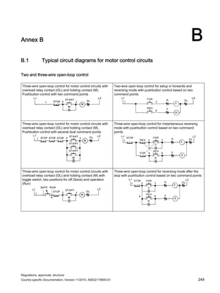
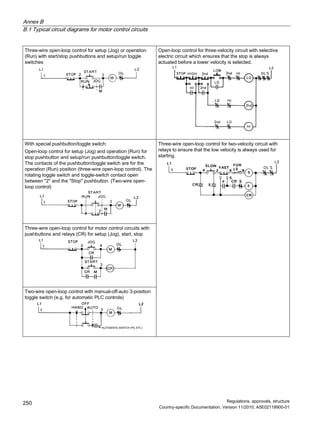

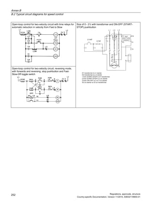
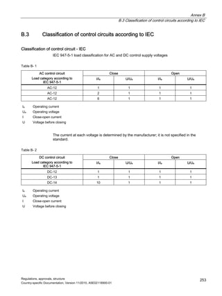
![Annex B
B.3 Classification of control circuits according to IEC
Regulations, approvals, structure
Country-specific Documentation, Version 11/2010, A5E02118900-01
254
Example of a typical IEC control circuit table for AC and DC 1
Table B- 3
Ie/AC-12
[A]
Ue
[V] AC
Ie/AC-15
[A]
24 6
110 6
220 / 230 6
10
380 / 440 6
Table B- 4
Voltage
[V]
Ie/DC-12
[A]
Ie/DC-13
[A]
24 6 3
60 5 1,5
110 2,5 0,7
230 1 0,3
1 Example: A control contact, designed for AC-15 with a rating of 6 A at 230 V, can close at 230 V/60 A and open at
6 A.
Ie Operating current
Ue Operating voltage
I Close-open current
U Voltage before closing](https://image.slidesharecdn.com/guide-to-industrial-control-panels-230922040019-c60a1df7/85/Guide-to-Industrial-Control-Panels-pdf-254-320.jpg)

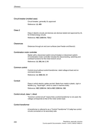
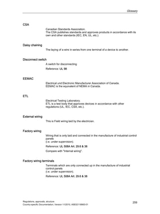
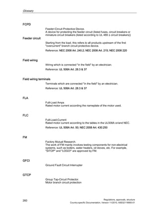
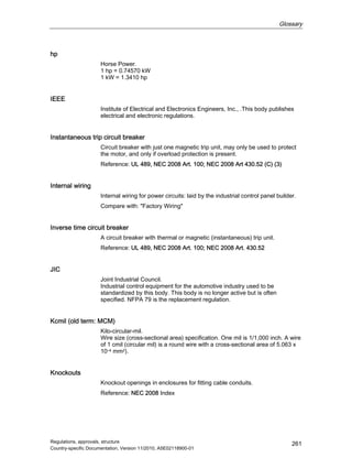
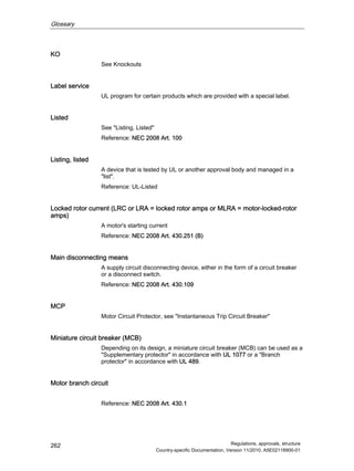
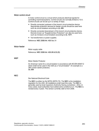
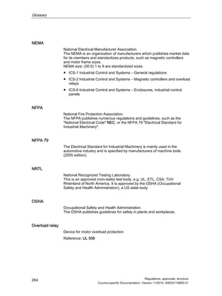
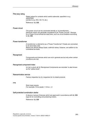
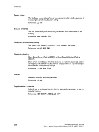
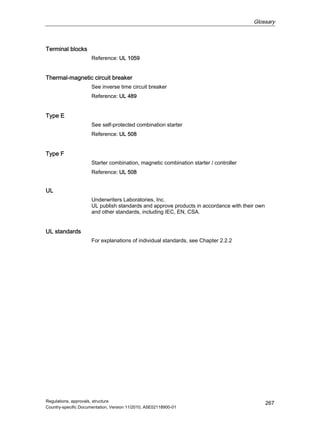


This document provides guidelines for manufacturers of industrial control panels for the North American market. It discusses relevant regulations from organizations like the National Electrical Code (NEC) and Underwriters Laboratories (UL). The guidelines cover topics like power and control circuits, enclosure requirements, short circuit protection, and sizing and selecting control devices. The intended audience is panel builders who need to understand North American standards for constructing safe and code-compliant control panels.


