SlideShare a Scribd company logo
1 of 4
Download to read offline
Series 150, 150S, 157, 157S
Bellows Replacement
Series 150Series 150S
• Before using product, read and understand instructions.
• Save these instructions for future reference.
• All work must be performed by qualified personnel trained in the proper application,
installation, and maintenance of plumbing, steam, and electrical equipment and/or systems
in accordance with all applicable codes and ordinances.
• To prevent electrical shock, turn off the electrical power before making electrical
connections.
• To prevent serious burns release all pressure and let boiler cool down to 80˚F (27˚C).
• Drain water level down below the float bowl chamber before taking the head mechanism
out of the body.
Failure to follow this warning could cause property damage, personal injury or death.
WARNING
CAU
TION
! WARNING
McDonnell & Miller
Installation & Maintenance
Instructions
MM-711(A)
2
OFF
ON
a. To prevent electrical shock turn off all electrical
power to the boiler.
CAUTION: There may be more than one source
of power to the boiler.
STEP 1 - Preparation
b. Release all pressure from the boiler and let it cool down to 80˚F (27˚C). Drain the water level
down below the float chamber.
c. Remove the four screws that hold the cover on the
switch housing (A) and remove the cover. Mark all
electrical supply wires so they can be returned to
the proper terminals. Remove the wires and conduit
connections from switch housing (A).
E
D
A
F
C
B
d. Remove eight hex head bolts holding head
mechanism (B) to float chamber. Carefully remove
head mechanism (B) from float chamber and place
in a vise.
e. Holding float (C) firmly, unscrew Allen® or Torx®
fastener (D). (Units with date codes of E99 or earlier
will have Allen® head fasteners. Those with codes of
F99 or later will have Torx® fastener). Unscrew float
and float rod (C). For snap switch units see Step 3a.
For mercury switch units remove the two mercury
switches. Remove six (6) Allen® or Torx® screws (E).
f. Remove switch housing (A) from head casting (B).
The bellows assembly (F) may stick to the switch
housing (A). Remove bellow assembly (F) and
clean gasket surfaces on both head casting (B) and
switch housing (A).
B
A
Four Cover
Screws
Eight Hex
Head Bolts
3
C
E
D
A
L
F
J
K
B
M
H
D
H
G
JK
STEP 2 - Changing the Bellows for Mercury Switch Units (For Snap Switch See STEP 3)
c. Make sure tapped hole on float arm (K) is facing the
correct way, so the float and float rod (C) can be
screwed into it when bellows assembly is assembled
on the head casting. Place gasket (M) on casting (B).
Center the gasket and place the bellows assembly (F)
and switch housing (A) on head casting (B). Insert and
tighten six (6) Torx® screws (E) to 125 in. lbs. (14 N•m).
d. Screw float and float rod (C) into float arm (K) and
hand tighten. Center the float rod in the float rod
guide (not shown) and tighten Torx screw (D) to
125 in. lbs. (14 N•m). Make sure you hold the float
in place while tightening screw (D). Move the float
up and down, making sure there is no binding and
that the float rod is still centered.
b. Take the new bellow assembly (F) and disassemble it
noting the order of the parts. Put sealing washer (J) on
top of float arm (K) and insert into inside of bellows (F).
Place gasket (L) over bellows (F). Insert this assembly
into switch housing (A) and bracket (H). If the screw (D)
was an Allen® screw, the spacer washer (G) will have to
be put in the top hole of bracket (H). Take Torx® screw (D)
(furnished) and insert it into hole on top of bracket (H) and
spacer washer (G) (if needed) and screw into float arm (K).
Hand tighten only.
a. NOTE: On units that have Allen® head screws they should
be replaced with Torx® screws (furnished).
B
C
J
F
A
G
D
P
N
R
E
Step 3 - Changing the Bellows for Snap Switch Units
a. Clean out sealant and remove two (2) screws (N)
and bracket (P). Remove (6) Allen® or Torx® screws
(E). Remove switch housing (A) from head casting (B).
The switch bracket (R) will come out with the switch
housing (A). The bellows assembly (F) may stick to
the switch housing (A). Remove bellow assembly (F)
and clean gasket surfaces on both head casting (B)
and switch housing (A).
e. Screw float and float rod (C) into float arm (K)
and hand tighten. Center the float rod in the float
rod guide (not shown) and tighten Torx® screw (D)
to 125 in. lbs. (14N•m). Make sure you hold the
float in place while tightening screw (D). Move the
float up and down, making sure there is no binding
and that the float rod is still centered. Install bracket
(P) using screws (N), tighten to 40 in. lbs.
(4.5 N•m).
a. Clean the gasket surface on head casting (B) and the body casting. Using a new gasket (furnished)
mount the head mechanism to the body casting. Tighten the eight (8) bolts to 18 ft. lbs. (24N•m).
Reattach conduit connectors and connect wires to the proper terminals. Turn on electrical power to the
boiler.
STEP 4 - Assembling the Head to the Body and Test for Proper Operation
b. Run the unit through several cycles of operation, noting the operating points. On the snap
switch controls it may be necessary to readjust the switches. If this is necessary follow the
enclosed instructions. (See attached for reference only, MM-235).
d. Make sure the tapped hole on float arm (K) is
facing the correct way, so the float and float
rod (C) can be screwed into it when bellows
assembly is assembled on the head casting.
Place gasket (M) on head casting (B). Center the
gasket and place the bellows assembly (F) and
the switch housing (A) on head casting (B). Insert
and tighten the six (6) Torx® screws (E) to 125 in.
lbs. (14N•m). Make sure that two (2) of the screws
capture the switch bracket (R).
D
H
G
JK
E
D
R
A
B
P
J
C
H
NL
F
K
M
c. Take the new bellows assembly (F) and disassemble
it noting the order of parts. Put sealing washer (J)
on top of float arm (K) and insert into inside of
bellows (F). Place gasket (L) over bellows (F).
Insert this assembly into switch housing (A) and
bracket (H). If the screw (D) was an Allen® screw,
the spacer washer (G) will have to be put in the top
hole of bracket (H). Take Torx® screw (D)
(furnished) and insert it into hole on top of bracket
(H) and spacer washer (G) (if needed) and screw
into float arm (K). Hand tighten only.
Step 3 - Changing the Bellows for Snap Switch Units cont’d)
b. NOTE: On units that have Allen® head screws they
will be replaced with Torx® screws (furnished).
ITT
8200 N. Austin Ave.
Morton Grove, IL 60053
tel: 847-966-3700
fax: 847-966-9052
www.mcdonnellmiller.com
©2007 ITT Corporation
Printed in U.S.A. 5-07 246765
McDonnell & Miller

More Related Content

What's hot

Puesta a tierra
Puesta a tierraPuesta a tierra
Puesta a tierra
Joan Pil
 
Manual para el procedimiento de pruebas hidrostáticas
Manual para el procedimiento de pruebas hidrostáticasManual para el procedimiento de pruebas hidrostáticas
Manual para el procedimiento de pruebas hidrostáticas
VCISARAHY
 
Sistema motriz o de energia final perforacion petrolera
Sistema motriz o de energia final perforacion petroleraSistema motriz o de energia final perforacion petrolera
Sistema motriz o de energia final perforacion petrolera
luis carlos saavedra
 

What's hot (20)

Bombas centrifugas
Bombas centrifugasBombas centrifugas
Bombas centrifugas
 
Examen de mecánico de Piso
Examen de mecánico de PisoExamen de mecánico de Piso
Examen de mecánico de Piso
 
Informe mc-bombas-warman-rev-0
Informe mc-bombas-warman-rev-0Informe mc-bombas-warman-rev-0
Informe mc-bombas-warman-rev-0
 
Tabla roscas a l-casillas-maquinas-calculos-de-taller
Tabla roscas  a l-casillas-maquinas-calculos-de-tallerTabla roscas  a l-casillas-maquinas-calculos-de-taller
Tabla roscas a l-casillas-maquinas-calculos-de-taller
 
Cunas y cuneros_estandar
Cunas y cuneros_estandarCunas y cuneros_estandar
Cunas y cuneros_estandar
 
Simbologia de soldadura
Simbologia de soldaduraSimbologia de soldadura
Simbologia de soldadura
 
BOMBAS - CURSO BOMBAS 1.ppt
BOMBAS - CURSO BOMBAS 1.pptBOMBAS - CURSO BOMBAS 1.ppt
BOMBAS - CURSO BOMBAS 1.ppt
 
Válvulas, selección, uso y mantenimiento richard w. greene
Válvulas, selección, uso y mantenimiento   richard w. greeneVálvulas, selección, uso y mantenimiento   richard w. greene
Válvulas, selección, uso y mantenimiento richard w. greene
 
simbologia.
simbologia.simbologia.
simbologia.
 
Puesta a tierra
Puesta a tierraPuesta a tierra
Puesta a tierra
 
Manual para el procedimiento de pruebas hidrostáticas
Manual para el procedimiento de pruebas hidrostáticasManual para el procedimiento de pruebas hidrostáticas
Manual para el procedimiento de pruebas hidrostáticas
 
Sistema motriz o de energia final perforacion petrolera
Sistema motriz o de energia final perforacion petroleraSistema motriz o de energia final perforacion petrolera
Sistema motriz o de energia final perforacion petrolera
 
mantenimiento soldadura
mantenimiento soldaduramantenimiento soldadura
mantenimiento soldadura
 
maxima demanda 2
maxima demanda 2maxima demanda 2
maxima demanda 2
 
Analisis bomba de varilla
Analisis bomba de varillaAnalisis bomba de varilla
Analisis bomba de varilla
 
Canalizacion unistrut
Canalizacion unistrutCanalizacion unistrut
Canalizacion unistrut
 
procedimiento-de-soldadura-wps-pdf
 procedimiento-de-soldadura-wps-pdf procedimiento-de-soldadura-wps-pdf
procedimiento-de-soldadura-wps-pdf
 
WPS y PQR Conforme al código D1.4 Structural Welding Code - Reinforcing Steel
WPS y PQR Conforme al código D1.4 Structural Welding Code - Reinforcing SteelWPS y PQR Conforme al código D1.4 Structural Welding Code - Reinforcing Steel
WPS y PQR Conforme al código D1.4 Structural Welding Code - Reinforcing Steel
 
Mechas o brocas
Mechas o brocasMechas o brocas
Mechas o brocas
 
THW - 90
THW - 90THW - 90
THW - 90
 

Recently uploaded

ALCOHOL PRODUCTION- Beer Brewing Process.pdf
ALCOHOL PRODUCTION- Beer Brewing Process.pdfALCOHOL PRODUCTION- Beer Brewing Process.pdf
ALCOHOL PRODUCTION- Beer Brewing Process.pdf
Madan Karki
 
21P35A0312 Internship eccccccReport.docx
21P35A0312 Internship eccccccReport.docx21P35A0312 Internship eccccccReport.docx
21P35A0312 Internship eccccccReport.docx
rahulmanepalli02
 
Maher Othman Interior Design Portfolio..
Maher Othman Interior Design Portfolio..Maher Othman Interior Design Portfolio..
Maher Othman Interior Design Portfolio..
MaherOthman7
 
Performance enhancement of machine learning algorithm for breast cancer diagn...
Performance enhancement of machine learning algorithm for breast cancer diagn...Performance enhancement of machine learning algorithm for breast cancer diagn...
Performance enhancement of machine learning algorithm for breast cancer diagn...
IJECEIAES
 
Online crime reporting system project.pdf
Online crime reporting system project.pdfOnline crime reporting system project.pdf
Online crime reporting system project.pdf
Kamal Acharya
 

Recently uploaded (20)

Module-III Varried Flow.pptx GVF Definition, Water Surface Profile Dynamic Eq...
Module-III Varried Flow.pptx GVF Definition, Water Surface Profile Dynamic Eq...Module-III Varried Flow.pptx GVF Definition, Water Surface Profile Dynamic Eq...
Module-III Varried Flow.pptx GVF Definition, Water Surface Profile Dynamic Eq...
 
SLIDESHARE PPT-DECISION MAKING METHODS.pptx
SLIDESHARE PPT-DECISION MAKING METHODS.pptxSLIDESHARE PPT-DECISION MAKING METHODS.pptx
SLIDESHARE PPT-DECISION MAKING METHODS.pptx
 
Passive Air Cooling System and Solar Water Heater.ppt
Passive Air Cooling System and Solar Water Heater.pptPassive Air Cooling System and Solar Water Heater.ppt
Passive Air Cooling System and Solar Water Heater.ppt
 
Worksharing and 3D Modeling with Revit.pptx
Worksharing and 3D Modeling with Revit.pptxWorksharing and 3D Modeling with Revit.pptx
Worksharing and 3D Modeling with Revit.pptx
 
NEWLETTER FRANCE HELICES/ SDS SURFACE DRIVES - MAY 2024
NEWLETTER FRANCE HELICES/ SDS SURFACE DRIVES - MAY 2024NEWLETTER FRANCE HELICES/ SDS SURFACE DRIVES - MAY 2024
NEWLETTER FRANCE HELICES/ SDS SURFACE DRIVES - MAY 2024
 
litvinenko_Henry_Intrusion_Hong-Kong_2024.pdf
litvinenko_Henry_Intrusion_Hong-Kong_2024.pdflitvinenko_Henry_Intrusion_Hong-Kong_2024.pdf
litvinenko_Henry_Intrusion_Hong-Kong_2024.pdf
 
Linux Systems Programming: Semaphores, Shared Memory, and Message Queues
Linux Systems Programming: Semaphores, Shared Memory, and Message QueuesLinux Systems Programming: Semaphores, Shared Memory, and Message Queues
Linux Systems Programming: Semaphores, Shared Memory, and Message Queues
 
Seismic Hazard Assessment Software in Python by Prof. Dr. Costas Sachpazis
Seismic Hazard Assessment Software in Python by Prof. Dr. Costas SachpazisSeismic Hazard Assessment Software in Python by Prof. Dr. Costas Sachpazis
Seismic Hazard Assessment Software in Python by Prof. Dr. Costas Sachpazis
 
ALCOHOL PRODUCTION- Beer Brewing Process.pdf
ALCOHOL PRODUCTION- Beer Brewing Process.pdfALCOHOL PRODUCTION- Beer Brewing Process.pdf
ALCOHOL PRODUCTION- Beer Brewing Process.pdf
 
Artificial Intelligence in due diligence
Artificial Intelligence in due diligenceArtificial Intelligence in due diligence
Artificial Intelligence in due diligence
 
21P35A0312 Internship eccccccReport.docx
21P35A0312 Internship eccccccReport.docx21P35A0312 Internship eccccccReport.docx
21P35A0312 Internship eccccccReport.docx
 
NO1 Best Powerful Vashikaran Specialist Baba Vashikaran Specialist For Love V...
NO1 Best Powerful Vashikaran Specialist Baba Vashikaran Specialist For Love V...NO1 Best Powerful Vashikaran Specialist Baba Vashikaran Specialist For Love V...
NO1 Best Powerful Vashikaran Specialist Baba Vashikaran Specialist For Love V...
 
Maher Othman Interior Design Portfolio..
Maher Othman Interior Design Portfolio..Maher Othman Interior Design Portfolio..
Maher Othman Interior Design Portfolio..
 
handbook on reinforce concrete and detailing
handbook on reinforce concrete and detailinghandbook on reinforce concrete and detailing
handbook on reinforce concrete and detailing
 
What is Coordinate Measuring Machine? CMM Types, Features, Functions
What is Coordinate Measuring Machine? CMM Types, Features, FunctionsWhat is Coordinate Measuring Machine? CMM Types, Features, Functions
What is Coordinate Measuring Machine? CMM Types, Features, Functions
 
Research Methodolgy & Intellectual Property Rights Series 2
Research Methodolgy & Intellectual Property Rights Series 2Research Methodolgy & Intellectual Property Rights Series 2
Research Methodolgy & Intellectual Property Rights Series 2
 
Performance enhancement of machine learning algorithm for breast cancer diagn...
Performance enhancement of machine learning algorithm for breast cancer diagn...Performance enhancement of machine learning algorithm for breast cancer diagn...
Performance enhancement of machine learning algorithm for breast cancer diagn...
 
Filters for Electromagnetic Compatibility Applications
Filters for Electromagnetic Compatibility ApplicationsFilters for Electromagnetic Compatibility Applications
Filters for Electromagnetic Compatibility Applications
 
Online crime reporting system project.pdf
Online crime reporting system project.pdfOnline crime reporting system project.pdf
Online crime reporting system project.pdf
 
Operating System chapter 9 (Virtual Memory)
Operating System chapter 9 (Virtual Memory)Operating System chapter 9 (Virtual Memory)
Operating System chapter 9 (Virtual Memory)
 

Fuelle mcdonnell-miller-125

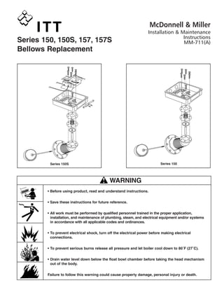
  • 1. Series 150, 150S, 157, 157S Bellows Replacement Series 150Series 150S • Before using product, read and understand instructions. • Save these instructions for future reference. • All work must be performed by qualified personnel trained in the proper application, installation, and maintenance of plumbing, steam, and electrical equipment and/or systems in accordance with all applicable codes and ordinances. • To prevent electrical shock, turn off the electrical power before making electrical connections. • To prevent serious burns release all pressure and let boiler cool down to 80˚F (27˚C). • Drain water level down below the float bowl chamber before taking the head mechanism out of the body. Failure to follow this warning could cause property damage, personal injury or death. WARNING CAU TION ! WARNING McDonnell & Miller Installation & Maintenance Instructions MM-711(A)
  • 2. 2 OFF ON a. To prevent electrical shock turn off all electrical power to the boiler. CAUTION: There may be more than one source of power to the boiler. STEP 1 - Preparation b. Release all pressure from the boiler and let it cool down to 80˚F (27˚C). Drain the water level down below the float chamber. c. Remove the four screws that hold the cover on the switch housing (A) and remove the cover. Mark all electrical supply wires so they can be returned to the proper terminals. Remove the wires and conduit connections from switch housing (A). E D A F C B d. Remove eight hex head bolts holding head mechanism (B) to float chamber. Carefully remove head mechanism (B) from float chamber and place in a vise. e. Holding float (C) firmly, unscrew Allen® or Torx® fastener (D). (Units with date codes of E99 or earlier will have Allen® head fasteners. Those with codes of F99 or later will have Torx® fastener). Unscrew float and float rod (C). For snap switch units see Step 3a. For mercury switch units remove the two mercury switches. Remove six (6) Allen® or Torx® screws (E). f. Remove switch housing (A) from head casting (B). The bellows assembly (F) may stick to the switch housing (A). Remove bellow assembly (F) and clean gasket surfaces on both head casting (B) and switch housing (A). B A Four Cover Screws Eight Hex Head Bolts
  • 3. 3 C E D A L F J K B M H D H G JK STEP 2 - Changing the Bellows for Mercury Switch Units (For Snap Switch See STEP 3) c. Make sure tapped hole on float arm (K) is facing the correct way, so the float and float rod (C) can be screwed into it when bellows assembly is assembled on the head casting. Place gasket (M) on casting (B). Center the gasket and place the bellows assembly (F) and switch housing (A) on head casting (B). Insert and tighten six (6) Torx® screws (E) to 125 in. lbs. (14 N•m). d. Screw float and float rod (C) into float arm (K) and hand tighten. Center the float rod in the float rod guide (not shown) and tighten Torx screw (D) to 125 in. lbs. (14 N•m). Make sure you hold the float in place while tightening screw (D). Move the float up and down, making sure there is no binding and that the float rod is still centered. b. Take the new bellow assembly (F) and disassemble it noting the order of the parts. Put sealing washer (J) on top of float arm (K) and insert into inside of bellows (F). Place gasket (L) over bellows (F). Insert this assembly into switch housing (A) and bracket (H). If the screw (D) was an Allen® screw, the spacer washer (G) will have to be put in the top hole of bracket (H). Take Torx® screw (D) (furnished) and insert it into hole on top of bracket (H) and spacer washer (G) (if needed) and screw into float arm (K). Hand tighten only. a. NOTE: On units that have Allen® head screws they should be replaced with Torx® screws (furnished). B C J F A G D P N R E Step 3 - Changing the Bellows for Snap Switch Units a. Clean out sealant and remove two (2) screws (N) and bracket (P). Remove (6) Allen® or Torx® screws (E). Remove switch housing (A) from head casting (B). The switch bracket (R) will come out with the switch housing (A). The bellows assembly (F) may stick to the switch housing (A). Remove bellow assembly (F) and clean gasket surfaces on both head casting (B) and switch housing (A).
  • 4. e. Screw float and float rod (C) into float arm (K) and hand tighten. Center the float rod in the float rod guide (not shown) and tighten Torx® screw (D) to 125 in. lbs. (14N•m). Make sure you hold the float in place while tightening screw (D). Move the float up and down, making sure there is no binding and that the float rod is still centered. Install bracket (P) using screws (N), tighten to 40 in. lbs. (4.5 N•m). a. Clean the gasket surface on head casting (B) and the body casting. Using a new gasket (furnished) mount the head mechanism to the body casting. Tighten the eight (8) bolts to 18 ft. lbs. (24N•m). Reattach conduit connectors and connect wires to the proper terminals. Turn on electrical power to the boiler. STEP 4 - Assembling the Head to the Body and Test for Proper Operation b. Run the unit through several cycles of operation, noting the operating points. On the snap switch controls it may be necessary to readjust the switches. If this is necessary follow the enclosed instructions. (See attached for reference only, MM-235). d. Make sure the tapped hole on float arm (K) is facing the correct way, so the float and float rod (C) can be screwed into it when bellows assembly is assembled on the head casting. Place gasket (M) on head casting (B). Center the gasket and place the bellows assembly (F) and the switch housing (A) on head casting (B). Insert and tighten the six (6) Torx® screws (E) to 125 in. lbs. (14N•m). Make sure that two (2) of the screws capture the switch bracket (R). D H G JK E D R A B P J C H NL F K M c. Take the new bellows assembly (F) and disassemble it noting the order of parts. Put sealing washer (J) on top of float arm (K) and insert into inside of bellows (F). Place gasket (L) over bellows (F). Insert this assembly into switch housing (A) and bracket (H). If the screw (D) was an Allen® screw, the spacer washer (G) will have to be put in the top hole of bracket (H). Take Torx® screw (D) (furnished) and insert it into hole on top of bracket (H) and spacer washer (G) (if needed) and screw into float arm (K). Hand tighten only. Step 3 - Changing the Bellows for Snap Switch Units cont’d) b. NOTE: On units that have Allen® head screws they will be replaced with Torx® screws (furnished). ITT 8200 N. Austin Ave. Morton Grove, IL 60053 tel: 847-966-3700 fax: 847-966-9052 www.mcdonnellmiller.com ©2007 ITT Corporation Printed in U.S.A. 5-07 246765 McDonnell & Miller