Fuel Processing And Energy Utilization Sonil Nanda Prakash Kumar Sarangi
Fuel Processing And Energy Utilization Sonil Nanda Prakash Kumar Sarangi
Fuel Processing And Energy Utilization Sonil Nanda Prakash Kumar Sarangi
Fuel Processing And Energy Utilization Sonil Nanda Prakash Kumar Sarangi
Fuel Processing And Energy Utilization Sonil Nanda Prakash Kumar Sarangi
1.
Fuel Processing AndEnergy Utilization Sonil
Nanda Prakash Kumar Sarangi download
https://ebookbell.com/product/fuel-processing-and-energy-
utilization-sonil-nanda-prakash-kumar-sarangi-10503734
Explore and download more ebooks at ebookbell.com
2.
Here are somerecommended products that we believe you will be
interested in. You can click the link to download.
Advances In Clean Hydrocarbon Fuel Processing Science And Technology M
Rashid Khan
https://ebookbell.com/product/advances-in-clean-hydrocarbon-fuel-
processing-science-and-technology-m-rashid-khan-4449244
Novel Materials For Catalysis And Fuel Processing Juan J Bravosuarez
https://ebookbell.com/product/novel-materials-for-catalysis-and-fuel-
processing-juan-j-bravosuarez-4633214
Fullchip Nanometer Routing Techniques Analog Circuits And Signal
Processing 1st Edition Tsungyi Ho
https://ebookbell.com/product/fullchip-nanometer-routing-techniques-
analog-circuits-and-signal-processing-1st-edition-tsungyi-ho-2124650
Thermochemical Processing Of Biomass Conversion Into Fuels Chemicals
And Power 1st Edition Robert C Brown
https://ebookbell.com/product/thermochemical-processing-of-biomass-
conversion-into-fuels-chemicals-and-power-1st-edition-robert-c-
brown-2514184
3.
Thermochemical Processing OfBiomass Conversion Into Fuels Chemicals
And Power 2nd Edition Robert C Brown
https://ebookbell.com/product/thermochemical-processing-of-biomass-
conversion-into-fuels-chemicals-and-power-2nd-edition-robert-c-
brown-10442260
Everyday Activities To Help Your Young Child With Autism Live Life To
The Full Simple Exercises To Boost Functional Skills Sensory
Processing Coordination And Selfcare Debra S Jacobs Dion E Betts
https://ebookbell.com/product/everyday-activities-to-help-your-young-
child-with-autism-live-life-to-the-full-simple-exercises-to-boost-
functional-skills-sensory-processing-coordination-and-selfcare-debra-
s-jacobs-dion-e-betts-4730038
Advances In Solid Oxide Fuel Cells Iii Ceramic And Engineering Science
Proceeding Volume 28 Issue 4 Narottam P Bansal
https://ebookbell.com/product/advances-in-solid-oxide-fuel-cells-iii-
ceramic-and-engineering-science-proceeding-volume-28-issue-4-narottam-
p-bansal-4299004
Fuel Processing For Fuel Cells 1st Edition Gunther Kolb
https://ebookbell.com/product/fuel-processing-for-fuel-cells-1st-
edition-gunther-kolb-2335856
Fuel Processing Editors Wolf Vielstich Arnold Lamm Hubert A Gasteiger
https://ebookbell.com/product/fuel-processing-editors-wolf-vielstich-
arnold-lamm-hubert-a-gasteiger-1203250
5.
FUEL PROCESSING ANDENERGY
UTILIZATION
Edited by
Sonil Nanda, Prakash Kumar Sarangi and Dai-Viet N. Vo
A Chapman & Hall Book
v
Contents
Preface..............................................................................................................................................vii
Editors................................................................................................................................................xi
Contributors.................................................................................................................................... xiii
Chapter 1Fossil Fuels versus Biofuels: Perspectives on Greenhouse Gas Emissions,
Energy Consumptions, and Projections........................................................................1
Kang Kang, Mingqiang Zhu, Guotao Sun, and Xiaohui Guo
Chapter 2 An Overview of Fossil Fuel and Biomass-Based Integrated Energy Systems:
Co-firing, Co-combustion, Co-pyrolysis, Co-liquefaction, and Co-gasification.........15
Ejaz Ahmad, Ayush Vani, and Kamal K. Pant
Chapter 3 Catalytic Conversion of Lignocellulosic Biomass into Fuels and Value-Added
Chemicals.................................................................................................................... 31
Shireen Quereshi, Suman Dutta, and Tarun Kumar Naiya
Chapter 4 Production and Characterization of Biodiesel through Catalytic Routes...................53
Yun Hin Taufiq-Yap and Nasar Mansir
Chapter 5 Recent Advances in Hydrogen Production through Bi-Reforming of Biogas............71
Tan Ji Siang, Doan Pham Minh, Sharanjit Singh, Herma Dina Setiabudi,
and Dai-Viet N. Vo
Chapter 6 Effects of Mesoporous Supports and Metals on Steam Reforming of Alcohols........93
Richard Y. Abrokwah, William Dade, Sri Lanka Owen, Vishwanath
Deshmane, Mahbubur Rahman, and Debasish Kuila
Chapter 7 Current Developments in the Production of Liquid Transportation Fuels
through the Fischer-Tropsch Synthesis......................................................................109
Venu Babu Borugadda and Ajay K. Dalai
Chapter 8 Production of Biolubricant Basestocks from Structurally Modified Plant Seed
Oils and Their Derivatives........................................................................................123
Venu Babu Borugadda, Vaibhav V. Goud, and Ajay K. Dalai
Chapter 9 Recent Advances in Consolidated Bioprocessing for Microbe-Assisted Biofuel
Production................................................................................................................. 141
Prakash Kumar Sarangi and Sonil Nanda
11.
vi Contents
Chapter 10Cultivation and Conversion of Algae for Wastewater Treatment and Biofuel
Production................................................................................................................. 159
Priyanka Yadav, Sivamohan N. Reddy, and Sonil Nanda
Chapter 11 Life-Cycle Assessment of Biofuels Produced from Lignocellulosic Biomass
and Algae.................................................................................................................. 177
Naveenji Arun and Ajay K. Dalai
Chapter 12 Synthetic Crude Processing: Impacts of Fine Particles on
Hydrotreating of Bitumen-Derived Gas Oil.............................................................. 187
Rachita Rana, Sonil Nanda, Ajay K. Dalai, Janusz A. Kozinski, and John Adjaye
Index...............................................................................................................................................207
12.
vii
Preface
Since the industrialrevolution, fossil fuels in the form of crude oil, gasoline, diesel, coal, and natu-
ral gas have dominated the global energy sector. The extensive use of fossil fuels is continually lead-
ing to the cumulative emission of greenhouse gases, which result in many adverse environmental
conditions such as air pollution, acid rain, global warming, and ozone layer depletion. The role of
energy conversion and utilization has become significantly important because of the fluctuations
in availability of energy resources and the volatility in the fuel prices. Moreover, the crude oil
industries based on fossil fuel resources have been facing many technical impediments such as high
carbon footprint, shortage of resources, unaccountable greenhouse gas emissions, and subsequent
environmental damage. The fuel refineries could be more competitive by increasing the energy effi-
ciency and eliminating wastes that degrade the environment and natural ecosystems.
The consumption of fossil fuels and the emission of greenhouse gases are closely associated with
each other. In recent years, there has been a paradigm shift in the global interest from fossil-based
energy sources to green fuels. Green fuels, especially biofuels, are produced from wide-ranging
organic waste resources that have numerous environmental and socio-economic benefits. Biofuels
have tremendous scope in supplementing the aggregating fuel demands, mitigating CO2 emissions,
ensuring energy security and economic sustainability, as well as preventing ecological degrada-
tion. Furthermore, when utilized in connection with fossil fuels through several co-processing tech-
nologies, biofuels could potentially bring many advantages to existing energy infrastructures. This
book provides current information on the production and utilization of fossil fuels and biofuels;
co-processing technologies for fossil energy and bioenergy; synthetic crude oil processing; waste-
to-energy and chemical generation; conversion of biomass through consolidated thermochemical,
hydrothermal and biochemical pathways; reforming technologies; techno-economic analysis; as
well as life-cycle assessment studies.
This book, consisting of 12 chapters, is dedicated to the new developments and prospects in energy
conversion and utilization as well as fuel processing and upgrading. Chapter 1 by Kang et al. provides
an all-inclusive overview of the comparison between fossil fuels and biofuels from an environmental
perspective. The chapter gives special attention to the rapidly increasing worldwide energy demand
and its environmental impacts related to greenhouse gas emissions. The chapter also discusses the
many potential advantages of biofuels and biorefining technologies over fossil fuel refineries.
Chapter 2 by Ahmad et al. introduces several fossil fuel and biofuel integrated energy systems
such as co-firing, co-combustion, co-pyrolysis, co-liquefaction, and co-gasification. The chapter
justifies the need of co-processing technologies that could bring many economic and environmen-
tal benefits such as mitigation of greenhouse gas emissions, high-energy efficiency, and circular
economy.
Chapter 3 by Quereshi et al. throws light on the catalytic conversion of lignocellulosic biomass
into value-added chemicals and fuel products. The chapter highlights the generation of 5-hydroxy-
methylfurfural, 5-ethoxymethylfurfural, levulinic acid, and ethyl levulinate from waste lignocel-
lulosic materials as the platform building block compounds to produce many commodity chemicals
and fuels. Several Brønsted and Lewis acid-catalyzed reactions such as depolymerization, isomeri-
zation, dehydration, and rehydration involved in the production of such value-added compounds are
discussed.
Chapter 4 by Taufiq-Yap and Mansir presents the catalyst-assisted production and characteriza-
tion of biodiesel from various feedstocks including edible oils, non-edible oils, microalgal oil, and
waste cooking oil. The chapter highlights several catalysts used in the production of biodiesel such
as homogeneous and heterogeneous catalysts as well as heterogeneous acid and heterogeneous solid
base catalysts.
13.
viii Preface
Chapter 5by Siang et al. recounts the recent advances in hydrogen production by bi-reforming
of biogas. The chapter systematically discusses the thermodynamic aspects, mechanisms, and
kinetics of bi-reforming methane including the influence of process parameters such as gas hourly
space velocity, reaction temperature, and feed composition. The catalysts involved in bi-reforming
methane and the effects of catalyst supports and promoters are also described.
Chapter 6 by Abrokwah et al. evaluates the performance of mesoporous supports and metals
for hydrogen production by steam reforming of alcohols. The study describes the synthesis and
characterization of various high surface area catalytic systems by a one-pot hydrothermal method
for steam reforming of methanol and glycerol. The activity and stability tests for the synthesized
catalysts during steam reforming of alcohols are methodically reported.
Chapter 7 by Borugadda and Dalai gives an overview of the current developments in the produc-
tion of liquid transportation fuels by Fischer-Tropsch synthesis. The chapter describes the advantages
of integrated routes for biomass-to-gas and gas-to-liquid conversion technologies. The technologi-
cal advancements, reaction chemistry, catalysis and reactor engineering involved in Fischer-Tropsch
process are also discussed.
Chapter 8 by Borugadda et al. describes the production of biolubricant basestocks from structur-
ally modified plant seed oils and their derivatives. The chapter elucidates the chemical composition,
structure, and properties of plant seed oils, as well as several essential reactions involved in biolu-
bricant generation such as epoxidation, hydroxylation, di-ester, tri-ester, and tetra-ester formation
by esterification and anhydrides addition.
Chapter 9 by Sarangi and Nanda is a synopsis of the recent advances in consolidated biopro-
cessing for microbe-assisted biofuel production. The chapter describes the involvement of several
solventogenic bacteria, filamentous fungi, and yeasts for bioconversion of lignocellulosic biomass
and organic wastes for bioethanol and biobutanol production. This chapter also highlights microbial
strain development, metabolic engineering, and bioprocess technologies in alcohol-based biofuel
production.
Chapter 10 by Yadav et al. reviews the cultivation and conversion of algae for wastewater treat-
ment and biofuel production. The chapter summarizes the aspects of algal metabolism and technol-
ogies involved in the cultivation and harvesting of algae. The role of algae in carbon sequestration
and wastewater treatment is described along with biofuel production through its conversion by
hydrothermal liquefaction.
Chapter 11 by Arun and Dalai is based on life-cycle assessment of biofuels produced from
lignocellulosic biomass and algae. The chapter describes different methodologies for life-cycle
assessment of biofuels. The impacts of fertilizers used for the cultivation of biofuel feedstocks on
the environmental credibility as well as the influence of by-products and co-products of biomass
conversion process on the environment are also discussed.
Chapter 12 by Rana et al. is the final chapter of the book, which is a review of synthetic crude
processing and the impacts of fine particles on hydrotreating bitumen-derived gas oil. The chapter
is a technical appraisal on the upgrading of bitumen, catalytic hydrotreating, and the mechanisms
of fine particle deposition. This chapter focuses on significant concepts in the hydrotreating of gas
oil with special emphasis on the physicochemical properties and behavior of fine particles present
in bitumen-derived gas oil during the industrial hydrotreating process.
This book is a unification of chapters relating to the cutting-edge applications of green tech-
nologies that could reinvigorate the conventional oil industries and consolidated biorefineries by
positioning them within a competitive energy market. This book also evaluates the potentials of
integrated fossil fuel and biofuel refineries in attaining a relatively low carbon footprint, circular
economy, and environmental sustainability.
14.
ix
Preface
The editors thankall the authors who contributed their scholarly materials to develop this book.
Our heartfelt thanks to CRC Press for providing the opportunity to publish this edited volume. We
appreciate the sincere efforts by the CRC Press publishing team led by Ms. Renu Upadhyay and
Ms. Shikha Garg for their editorial assistance in preparing this book.
Sonil Nanda
Department of Chemical and Biochemical Engineering
University of Western Ontario
London, Ontario, Canada
Prakash Kumar Sarangi
Directorate of Research
Central Agricultural University
Imphal, Manipur, India
Dai-Viet N. Vo
Faculty of Chemical and Natural Resources Engineering
Universiti Malaysia Pahang
Kuantan, Pahang, Malaysia
16.
xi
Editors
Sonil Nanda isa research fellow at the University of Western
Ontario in London, Ontario, Canada. He earned his PhD in Biology
from York University, Toronto, Ontario, Canada; MSc in applied
microbiology from Vellore Institute of Technology (VIT
University), Tamil Nadu, India; and BSc in microbiology from
Orissa University of Agriculture and Technology, Bhubaneshwar,
Odisha, India. Dr. Nanda’s research areas are related to the produc-
tion of advanced biofuels and biochemicals through thermochemi-
cal and biochemical conversion technologies such as gasification,
pyrolysis, carbonization, and fermentation. He has expertise in
hydrothermal gasification of a wide variety of organic wastes and
biomass including agricultural and forestry residues, industrial
effluents, municipal solid wastes, cattle manure, sewage sludge,
and food wastes to produce hydrogen fuel. His parallel interests are also in the generation of hydro-
thermal flames for treatment of hazardous wastes, agronomic applications of biochar, phytoremedia-
tion of heavy metal contaminated soils, as well as carbon capture and sequestration. Dr. Nanda has
published more than 65 peer-reviewed journal articles, 15 book chapters, and has presented at many
international conferences. He serves as a fellow member of the Society for Applied Biotechnology in
India, as well as a life member of the Indian Institute of Chemical Engineers, Association of
Microbiologists of India, Indian Science Congress Association, and the Biotech Research Society of
India. He is also an active member of several chemical engineering societies across North America
such as the American Institute of Chemical Engineers, the Chemical Institute of Canada, and the
Combustion Institute-Canadian Section.
Prakash Kumar Sarangi is a scientist with specialization in food
microbiology at Central Agricultural University in Imphal, India.
He earned his PhD in microbial biotechnology specialization from
Botany department, Ravenshaw University, Cuttack, India; MTech
in applied botany from Indian Institute of Technology Kharagpur,
India; and MSc in botany from Ravenshaw University, Cuttack,
India. Dr. Sarangi’s current research is focused on bioprocess
engineering, renewable energy, biochemicals, biomaterials, fer-
mentation technology, and post-harvest engineering and technol-
ogy. He has expertise in bioconversion of crop residues and
agro-wastes into value-added phenolic compounds. He has more
than 10 years of teaching and research experience in biochemical
engineering, microbial biotechnology, downstream processing,
food microbiology, and molecular biology. He has served as a reviewer for many international jour-
nals, published more than 40 research articles in peer-reviewed journals, and authored more than 15
book chapters. He has published approximately 50 national and international conference papers. He
is associated with many scientific societies as a fellow member (Society for Applied Biotechnology)
and life member (Biotech Research Society of India; Society for Biotechnologists of India;
Association of Microbiologists of India; Orissa Botanical Society; Medicinal and Aromatic Plants
Association of India; Indian Science Congress Association; Forum of Scientists, Engineers &
Technologists; and International Association of Academicians and Researchers).
17.
xii Editors
Dai-Viet N.Vo earned his PhD in chemical engineering from the
University of New South Wales in Sydney, Australia, in 2011. He
has worked as a postdoctoral fellow at the University of New South
Wales in Sydney and Texas A&M University at Qatar, Doha. He is
currently a senior lecturer at the Faculty of Chemical & Natural
Resources Engineering in Universiti Malaysia Pahang in Kuantan,
Malaysia. His research areas are the production of green synthetic
fuels via Fischer-Tropsch synthesis using biomass-derived syngas
from reforming processes. He is also an expert in advanced mate-
rial synthesis and catalyst characterization. During his early
career, he has worked as the principal investigator and co-
investigator for 19 different funded research projects related to
sustainable and alternative energy. He has published 2 books, 3
book chapters, 50 peer-reviewed journal articles, and more than 60 conference proceedings. He has
served on the technical and publication committees of numerous international conferences in chem-
ical engineering and as the guest editor for some special issues in the International Journal of
Hydrogen Energy (Elsevier) and Catalysts (MDPI). He is also a regular reviewer for many presti-
gious international journals.
18.
xiii
Contributors
Richard Y. Abrokwah
Departmentof Energy and Environmental
Systems
North Carolina A&T State University
Greensboro, North Carolina
John Adjaye
Syncrude Edmonton Research Centre
Edmonton, Canada
Ejaz Ahmad
Department of Chemical Engineering
Indian Institute of Technology Delhi
New Delhi, India
Naveenji Arun
Department of Chemical and Biological
Engineering
University of Saskatchewan
Saskatoon, Canada
Venu Babu Borugadda
Department of Chemical and Biological
Engineering
University of Saskatchewan
Saskatoon, Canada
William Dade
Department of Chemistry
North Carolina A&T State University
Greensboro, North Carolina
Ajay K. Dalai
Department of Chemical and Biological
Engineering
University of Saskatchewan
Saskatoon, Canada
Vishwanath Deshmane
Department of Chemistry
North Carolina A&T State University
Greensboro, North Carolina
Suman Dutta
Department of Chemical Engineering
Indian Institute of Technology Dhanbad
(Indian School of Mines)
Dhanbad, India
Vaibhav V. Goud
Department of Chemical Engineering
Indian Institute of Technology Guwahati
Guwahati, India
Xiaohui Guo
College of Mechanical and Electronic
Engineering
Northwest A&F University
Yangling, China
Kang Kang
College of Mechanical and Electronic
Engineering
Northwest A&F University
Yangling, China
Janusz A. Kozinski
Department of Chemical Engineering
University of Waterloo
Waterloo, Canada
Debasish Kuila
Department of Chemistry
North Carolina A&T State University
Greensboro, North Carolina
Nasar Mansir
Catalysis Science and Technology Research
Centre
Universiti Putra Malaysia
Serdang, Malaysia
Doan Pham Minh
Université de Toulouse
IMT Mines Albi
Albi, France
19.
xiv Contributors
Tarun KumarNaiya
Department of Petroleum Engineering
Indian Institute of Technology Dhanbad
(Indian School of Mines)
Dhanbad, India
Sonil Nanda
Department of Chemical and Biochemical
Engineering
University of Western Ontario
London, Canada
Sri Lanka Owen
Department of Chemistry
North Carolina A&T State University
Greensboro, North Carolina
Kamal K. Pant
Department of Chemical Engineering
Indian Institute of Technology Delhi
New Delhi, India
Shireen Quereshi
Department of Chemical Engineering
Indian Institute of Technology Dhanbad
(Indian School of Mines)
Dhanbad, India
Mahbubur Rahman
Department of Chemistry
North Carolina A&T State University
Greensboro, North Carolina
Rachita Rana
Department of Chemical and Biological
Engineering
University of Saskatchewan
Saskatoon, Canada
Sivamohan N. Reddy
Department of Chemical Engineering
Indian Institute of Technology Roorkee
Roorkee, India
Prakash Kumar Sarangi
Directorate of Research
Central Agricultural University
Imphal, India
Herma Dina Setiabudi
Faculty of Chemical and Natural Resources
Engineering
University Malaysia Pahang
Kuantan, Malaysia
Tan Ji Siang
Faculty of Chemical and Natural Resources
Engineering
University Malaysia Pahang
Kuantan, Malaysia
Sharanjit Singh
Faculty of Chemical and Natural Resources
Engineering
University Malaysia Pahang
Kuantan, Malaysia
Guotao Sun
College of Mechanical and Electronic
Engineering
Northwest A&F University
Yangling, China
Yun Hin Taufiq-Yap
Catalysis Science and Technology Research
Centre
Universiti Putra Malaysia
Serdang, Malaysia
Ayush Vani
Department of Textile Technology
Indian Institute of Technology Delhi
New Delhi, India
Dai-Viet N. Vo
Faculty of Chemical and Natural Resources
Engineering
Universiti Malaysia Pahang
Kuantan, Malaysia
Priyanka Yadav
Department of Chemical Engineering
Indian Institute of Technology Roorkee
Roorkee, India
Mingqiang Zhu
College of Mechanical and Electronic
Engineering
Northwest A&F University
Yangling, China
20.
1
1 Fossil Fuelsversus Biofuels
Perspectives on Greenhouse
Gas Emissions, Energy
Consumptions, and Projections
Kang Kang, Mingqiang Zhu, Guotao Sun, and Xiaohui Guo
1.1 INTRODUCTION
Fossil fuels have been explored and used extensively for many centuries, and consumption became
particularly intensive after the industrial revolution, which occurred in the late eighteenth and nine-
teenth centuries. Currently, the major contributors of fossil energy include coal, oil, and natural gas
(Armaroli and Balzani 2011). The chemical energy stored in the hydrocarbons of fossil fuels has
been utilized in various ways (e.g., in the direct combustion for generating heat or power, in the con-
version to other value-added chemicals, or in further conversion to industrially relevant products by
physiochemical or biological routes). Despite its increasing demand, many are criticizing the fossil
fuel-based energy system due to the concerns over depletion of resources, pollution problems, ris-
ing fuel prices, and increasing political concerns (Luque et al. 2008; Nanda et al. 2015). One of the
most severe issues is the emission of greenhouse gases related to fossil fuel burning in developed
and developing countries (Chavez-Rodriguez and Nebra 2010). The industries have explored and
implemented many types of alternatives including hydropower, solar, wind, geothermal, wave, and
biomass that could potentially mitigate the greenhouse gas emissions with low carbon footprints
(Panwar et al. 2011; Nanda et al. 2017b).
Among all the alternatives, biofuels derived from biomass have attracted great interests world-
wide due to their carbon-neutral nature (Basu 2010). By far, biofuels have been developed for many
generations and generated various forms of biofuels including bioethanol, biobutanol, biodiesel,
bio-oil, bio-char, biomass fuel pellets, and biobased-syngas (Nanda et al. 2014b; Remón et al. 2016;
Kasmuri et al. 2017; Kang et al. 2018). Currently, biofuels cannot entirely replace fossil fuel due
to certain limitations such as poor fuel properties, higher production cost, low yield, need for fuel
CONTENTS
1.1 Introduction...............................................................................................................................1
1.2 Fossil Fuel: A Historical Overview...........................................................................................2
1.3 Environmental Issues Related to Fossil Fuels...........................................................................4
1.4 Greenhouse Gas Emissions from Fossil Fuels..........................................................................5
1.5 Research on Biofuels: Drivers and Benefits..............................................................................6
1.5.1 Current Status of Biofuels.............................................................................................7
1.5.2 Basic Concept of Biorefinery.........................................................................................9
1.6 Potentials in Biofuel Development............................................................................................9
1.6.1 Obtaining Sustainable Feedstocks at Low Cost............................................................9
1.6.2 Developing Biomass Processing Technologies with High Efficiency.........................10
1.7 Conclusions.............................................................................................................................. 11
References......................................................................................................................................... 11
21.
2 Fuel Processingand Energy Utilization
upgrading technologies, and engine modifications. However, biofuels have shown great potential
for sustainability. Moreover, findings show that recycling of biomass and other bio-based waste
materials for energy production boosts rural economy, employment opportunities, energy security,
and carbon neutrality (Nanda et al. 2015; Voloshin et al. 2016; Rodionova et al. 2017; Stephen
and Periyasamy 2018). Many countries have started subsidizing the production and utilization
of biofuels, whereas researchers are still debating on the net-benefits of switching from fossil to
bio-based energy systems.
To get a clear idea of the future direction of the fuel research, it is neccessary to compare the
existing challenges and opportunities between fossil fuels and biofuels. With all the trends men-
tioned, it is obvious that, for a considerate period, fossil energy system will continue to remain the
main source of energy that we rely on but will be augmented by many other renewables sources,
including biofuels in the near future. Based on this trend, this chapter provides a general overview
of the comparison between fossil fuels and biofuels. Special attention is given to the environmental
impacts such as greenhouse gas emissions, energy consumptions, but the details about different
conversion processes and fuel upgrading technologies are not the focus of this chapter. The projec-
tions on energy utilization are also made based on the knowledge obtained from the literature.
1.2 FOSSIL FUEL: A HISTORICAL OVERVIEW
The fossil fuels including coal, lignite, oil shales, tar, asphalt, petroleum, and natural gas have been
used as the main sources of fuels since the industrial revolution. The name fossil fuels arise from
their production from fossilized remains of living organisms deep under the Earth’s crust for thou-
sands of years as hydrocarbons. On the other hand, biofuels are a result of photosynthesis by the
green plants that converts and stores solar energy in the form of carbohydrates, a chemical energy.
However, human civilization was solely dependent on the energy from sunlight and dried plant
biomass until the thirteenth century, when coal was discovered. Since the nineteenth century, the
extraction and utilization of petroleum and natural gas significantly broadened the spectra of fossil
energy resources.
The production and utilization routes of fossil fuels have been significantly advanced by the
development in related research areas in geochemistry as well as in chemical, mechanical, and civil
engineering. With the world’s increasing population, prosperity, and economic growth following
the industrial revolution, the pursuit for cost effectiveness and reliability in supplying fossil fuels
has compromised environmental sustainability. In the twenty-first century, the exploitation of fos-
sil fuels has been at a dramatic pace. Therefore, the sustainability should be given high priority
when developing any energy-related technologies or implementing energy-related policies (Chu and
Majumdar 2012). Fossil fuel-based energy systems play a dominant role in the energy supply sector
because most of the energy supply is from crude oil (e.g., petroleum, diesel, and kerosene), natural
gas, and coal. The worldwide liquid fuels consumption is shown in Figure 1.1. From the figure, it is
obvious that in recent years the total consumption is steadily increasing (USEIA 2018c).
With the fast pace of industrialization and urbanization in developing counties such as China
and India, unless a dramatic breakthrough occurs in the energy sector, the global energy demand
will be gradually increasing in the near future. And most of the energy will still be from the fossil
fuel resources since they are still more reliable, cheaper, and more efficient, and easier to produce,
store, and transport, (Biresselioglu and Yelkenci 2016). Above all, based on the current situation,
the basic strategy is improving the utilization efficiency of fossil fuels while searching for alterna-
tive green fuels.
The basic concept of conventional fossil energy recovery is maximizing the energy recovery
using different technologies including purification through physical or chemical separation such
as fractional distillation, pressure swing adsorption, membrane separation, solvent extraction, and
so on. The chemical conversion technologies available for upgrading the fossil fuels or utilizing
their by-products are catalytic cracking, liquefaction, reforming (using steam or CO2), gasification,
22.
3
Fossil Fuels versusBiofuels
Fischer-Tropsch (FT) synthesis, and so on (Anthony and Howard 1976; Babich and Moulijn 2003;
Thomas and Dawe 2003).
As shown in Figure 1.2, the processing or conversion routes of coal, natural gas, and crude oil are
different, but they share some critical technologies, which point to the same final products such as
conversion into H2 by reforming and upgrading of syngas into other fuels through Fischer-Tropsch
synthesis. In addition, the transformation of fossil fuel to the synthetic final products often requires
a combination of two or more processes and considerable amounts of energy input. Traditionally,
the energy and carbon balance is compensated by other forms of fossil energy, which in turn leads to
further consumption of fossil energy and drives the demand for developing highly efficient recovery
technologies. Therefore, the development of greener processes that could generate cleaner fuels
seems to be direction of the future.
Many academic researchers and industrial leaders are dedicated to developing technologies that
could boost the efficiency of fossil energy utilization, thus yielding novel conversion and upgrading
routes featuring high-efficiency, cost-effectiveness and eco-friendless. An interesting example is
the chemical looping processes such as chemical looping combustion (CLC) and chemical looping
reforming (CLR), which cover a wide range for the utilization of solid, gaseous, and liquid fuels
(Tang et al. 2015). The CLC process does not involve any direct mixing of air and fuel, but a solid
oxygen carrier (normally a metal oxide) supplies the oxygen through a redox cycle. The oxygen
carrier is first reduced to supply the oxygen and then oxidized with air. By the exclusion of the gas
separation step, CLC can gain dramatic energy savings compared to conventional combustion tech-
nologies (Adánez et al. 2018). Another example would be the development of hybrid, battery, and
fuel-cell electric vehicles, which are being developed to mitigate the dependency on conventional
vehicular fuels and the adverse effects of related greenhouse gas emissions. Although the poor
energy density of batteries and capacitors is hindering their practical utilization, their reducing costs
and innovation in technology is also creating future potentials (Pollet et al. 2012). Moreover, the
FIGURE 1.1 Worldwide liquid fuels consumption. (Data adapted from USEIA, Short-term energy outlook,
March 2018, United States Energy Information Administration, https://www.eia.gov/outlooks/steo/USEIA,
2018c.)
23.
4 Fuel Processingand Energy Utilization
idea of coupling renewable energy (e.g., solar, wind, water, geothermal, and biomass) with the fossil
energy-based system seems to be a promising way to reduce energy consumption in the foreseeable
future. In addition, the advances in novel materials such as catalysts, electrodes, reactor coatings,
and so on may lead to breakthroughs in fossil fuel energy technologies.
1.3 ENVIRONMENTAL ISSUES RELATED TO FOSSIL FUELS
Other than the energy crisis, fossil fuel utilization also causes many environmental problems, which
involves issues in the atmosphere, hydrosphere, biosphere, and lithosphere. The hydrocarbon com-
position of the fossil fuels when decomposed or transformed releases many unwanted chemicals,
emissions, and particulate matter, which potentially lead to environmental problems. Also, the
existing technologies for the utilization of fossil fuels, although improving, are still not capable of
preventing the formation and release of these contaminants into the environment and available pre-
vention technologies often are too expensive to be fully implemented at a commercial level.
FIGURE 1.2 Simplified routes for the conventional conversions of (a) coal, (b) natural gas, and (c) crude oil.
24.
5
Fossil Fuels versusBiofuels
The most commonly studied environmental issues which could be correlated to fossil fuel uti-
lization is air pollution. A good example is photochemical smog, which is formed mainly due to
emissions of volatile organic compounds (VOCs) and NOx gases from motor vehicles and industrial
sources (Rye 1995). The issue of haze-fog pollution in China, although formed by interrelated rea-
sons, seems to be closely related to vehicular emissions from the extensive use of fossil energy and
fuel combustion for industries and for domestic heating (Fu and Chen 2017).
Moreover, the impact of fossil fuel utilization also extends to water bodies. The discharge of
effluents from power stations, fuel refineries, or chemical processing industries contain many haz-
ardous and volatile components, which may mix with the surface water and/or groundwater and
disperse widely within a short time (Reddy et al. 2016). In addition, the effluents, coolants, and
recycled water used for cooling purposes and released by a power plant or fuel refinery may also
contain dissolved chemicals which could cause contamination if not treated properly before dis-
posal (Macqueen 1980).
The direct impact of the fossil energy system on the lithosphere mainly is mining where the fos-
sil fuel precursors are buried. During the mining process, geological structures of the sites undergo
different extents of destruction and might not recover. In addition, the migration and transformation
behavior of some fossil fuel-derived contaminants could cause them potentially to participate in
different types of environmental issues. In addition, some uneven weather conditions are indirectly
linked to the greenhouse gas emissions and global warming caused by the increasing usage of fos-
sil fuels such as acid rain, increase in the atmospheric temperature, droughts, storms, increase in
the sea level, and so on. Other than the environmental issues mentioned, an unavoidable concern
correlated to the fossil energy is the enormous quantities of CO2, CH4, SOx, and NOx emissions,
which are the major sources of greenhouse gas emissions that accelerate global warming. In recent
years, CO2 emissions from fossil fuel sources have raised serious concerns about the effects on the
environment and human health.
1.4 GREENHOUSE GAS EMISSIONS FROM FOSSIL FUELS
Different types of fossil fuels emit different amounts of CO2 into the atmosphere when burned.
The analysis of emissions across the fossil fuels could be achieved by comparing the amount of
CO2 emitted per unit of energy generated or heat content. Generally, the amount of CO2 released by
different types of fossil fuels follows the order of coal > diesel > gasoline > natural gas (USEIA
2018a). The amount of CO2 produced during the combustion of a fuel is dependent mainly on the
content of carbon and hydrogen in the fuel. Since natural gas (methane) mainly consists of only
carbon and hydrogen, it has relatively higher energy content than other fossil fuels and releases the
lowest content of CO2 when combusted. Therefore, natural gas is considered to be a cleaner fuel than
other types of fossil fuels. However, methane is considered 30 times more potent as a heat-trapping
gas (Kelly 2014). The disadvantage of natural gas lies in its uneven distribution worldwide and its
limited reserve. Facing the current carbon scenario and the stringent regulations on sulfur level
in fuels, the valorization of the natural gas reserves into liquid fuels through the Fischer-Tropsch
process has raised significant interest in recent years (Perego et al. 2009).
Coal is more abundant than natural gas and is still the dominant source of fossil energy for many
countries, yet it is also considered the highest CO2 emitter. In addition, the combustion of coal is
usually the dominant source of CO2 emission for developing countries like China and India, which
still rely on coal as a major source for electricity and steam (Govindaraju and Tang 2013; Chen et al.
2016). Hence, controlling of the CO2 emissions from coal is critical in the long run. Normally, the
source of coal or the manner of coal utilization cause differences in the CO2 emission because the
low-rank coals emit higher CO2 than the high-rank coals. Significant reduction in CO2 emissions
from coal could be achieved by implementing alternative technologies such as the integrated gas-
ification combined cycle (IGCC) or deploying carbon capture and storage (CCS) facilities (Skodras
et al. 2015; Nanda et al. 2016b, 2016c).
25.
6 Fuel Processingand Energy Utilization
The liquid fossil fuels such as diesel and gasoline show intermediate levels of CO2 emission, which
is lower than coal but higher than natural gas. In addition, diesel-powered vehicles show higher fuel
economy and lower CO2 emissions than gasoline-powered vehicles (Sullivan et al. 2004). Other than
modification of vehicular engines, which has never stopped evolving, a critical strategy for reducing
the CO2 emission from liquid fossil fuel utilization is blending with biofuels such as biodiesel, bio-
ethanol, and biobutanol (Balat and Balat 2009; Mata et al. 2010; Nanda et al. 2014a, 2017a).
Less CO2 emission could be achieved by optimizing the fossil fuel utilization network such as
using more natural gas, developing clean coal technologies, and enhancing the efficiency of liquid
fuel production. Compared to biofuels, the CO2 released during the burning of fossil fuels is con-
sidered to increase their atmospheric levels because the emitted CO2 could not be recycled within a
short period of time unlike for biofuels.
The CO2 emissions caused by the energy consumption in the United States over decades is plotted
in Figure 1.3 (USEIA 2018b). As shown in the figure, from 1950 to 2016, the CO2 emission caused
by energy consumption increased dramatically until maximum emission in 2007. After 2007, emis-
sions flucuated with a slight reduction. The declining trend in emissions per capita might possibly
be due to public awareness to reduce carbon emissions and advances in energy-saving technologies.
However, many countries are still consuming increasing amount of energy every year, and these
uneven contributions to the CO2 emission bring serious challenges to the global community to find
effective and equitable solutions.
1.5 RESEARCH ON BIOFUELS: DRIVERS AND BENEFITS
It becomes increasingly important to seek a more sustainable method for societal development
due to the increasing global energy demands, the limiting fossil fuel reserves, the need to reduce
greenhouse gas emissions, and the fluctuating crude oil prices. Therefore, a cost-competitive and
reliable solution is needed to reduce fossil fuel dependency and to achieve potential reductions in
greenhouse gas. Consequently, it is necessary to search for a cleaner, more secure, and affordable
fuels for transportation to drive a low-carbon technology. In this regard, biofuels which are often
produced from plants or other organic wastes, have emerged to make significant contributions to a
carbon neutral fuel economy (Naik et al. 2010).
One of the major advantages of biofuel over fossil fuels is the potential reduction of CO2 emission
since the amount emitted burning could be recycled by plants through the photosynthesis process
and fixed in the newly generated biomass. The emissions of CO2 from the utilization of different
biofuels are shown in Figure 1.4 (USEIA 2018b). The total emission of CO2 from biofuel utilization
15.0
16.0
17.0
18.0
19.0
20.0
21.0
22.0
2000
2500
3000
3500
4000
4500
5000
5500
6000
6500
1950
1965
1980
1983
1986
1989
1992
1995
1998
2001
2004
2007
2010
2013
2016
Metric
tons
CO
2
Million
metric
tons
CO
2
Emissions
Emissions per capita
FIGURE 1.3 CO2 emissions from energy consumption over the years. (Data adapted from USEIA, Monthly
energy review, March 2018, United States Energy Information Administration, https://www.eia.gov/
totalenergy/
data/monthly/pdf/mer.pdf, 2018b.)
26.
7
Fossil Fuels versusBiofuels
fluctuates, although the emissions increased in 2014 and then decreased gradually. In terms of dif-
ferent biofuels, the CO2 emission from burning wood is at a the highest followed by bioethanol, solid
biomass wastes, and biodiesel.
1.5.1 Current Status of Biofuels
Biofuels can be produced from a wide range of biomass sources through many promising technolo-
gies to fulfill the targets of using bio-based renewable resources and mitigating greenhouse gas
emissions (Gaurav et al. 2017). Many thermochemical (e.g., pyrolysis, gasification, liquefaction,
torrefaction, and combustion) and biochemical technologies (e.g., fermentation, anaerobic digestion,
and microbial fuel cells) can convert biomass and other organic wastes to produce diverse biofuels
such as bio-oil, biodiesel, bioethanol, biobutanol, hydrogen, syngas, bio-char, green electricity, and
heat (Nanda et al. 2014a, 2015, 2016a, 2017b). Based on the type of the sources of biomass used, the
biofuels could be categorized into first-, second-, and third-generation biofuels (Alam et al. 2015).
As shown in Figure 1.5, the first-generation biofuels such as bioethanol and biodiesel are produced
directly from conventional food crops including corn, maize, sugarcane, rapeseed, and soybean. The
production of first-generation biofuels is mainly through mature processes, which have been widely
used commercially due to its cost-effectiveness, time-efficiency, and techno-economic feasibility.
The alcohol fermented from sugars and starch currently is used in many countries as additives to
gasoline. Another first-generation biofuel (i.e., biodiesel) is produced from vegetable oil or animal
fat through transesterification. Biodiesel can be an alternative to petroleum diesel. However, the
most contentious issue related to first-generation biofuels is that the biomass precursors used for
biofuel production often compete with the food crops and arable lands for their cultivation.
To avoid the issue of food-versus-fuel, second-generation biofuels are produced from non-food
sources such as dedicated energy crops and waste biomass residues. The second-generation biofuels
are produced mostly from non-edible lignocellulosic biomass such as agricultural biomass (e.g., straws,
grasses, husk, shell, seed carps, etc.) and forest residues (e.g., woody biomass, sawdust, dead trees, etc.)
(Nanda et al. 2013). The processes to generate second-generation biofuels usually require a physico-
chemical, biochemical, or hydrothermal pretreatment to release the trapped sugars from the biomass
for conversion to biofuels. This process requires more cost, energy, and materials compared to first-
generation biofuels. Although the second-generation biofuels overcome the criticism of first-generation
biofuels, they are limited in being cost competitive to existing fossil fuels. However, the technology
for second-generation biofuels production is under development, so they still have the potential for
reduced processing costs and improved production efficiency with technological advances.
0
50
100
150
200
250
300
350
400
2005
2006
2007
2008
2009
2010
2011
2012
2013
2014
2015
2016
2017
Million
metric
tons
of
CO
2
Wood Biomass waste Fuel ethanol Biodiesel
FIGURE 1.4 Emissions of CO2 from biofuel and bioenergy utilization by different fuels. (Data source from
USEIA, Monthly energy review March 2018, United States Energy Information Administration, https://www.
eia.gov/totalenergy/data/monthly/pdf/mer.pdf, 2018b.)
27.
8 Fuel Processingand Energy Utilization
Third-generation biofuels mostly use algae and photosynthetic bacteria as the feedstocks. Mature
algal species are subjected to enzymatic, physicochemical, or hydrothermal extraction processes to
obtain oil, which is then processed to produce biodiesel or refined into other petroleum-based fuels
like bioethanol, biopropanol, and biohydrogen. The major advantage of algae is that it can grow in
photobioreactors and open ponds that do not compete with arable agricultural lands as in the case of
first-generation biofuels. However, further research is required still to make algal cultivation more
economically and environmentally sustainable and cost-competitive with petroleum, diesel, and other
fossil fuels.
The trends in global biofuel production by different regions in recent years are shown in
Figure 1.6. As the data indicates, the global production of biofuels has been increasing over the last
ten years; however, North, South, and Central America and Europe are significantly ahead of other
regions in the total amount produced, indicating that there is still a gap between the developed and
developing areas in adopting biofuel production and utilization.
FIGURE 1.5 Different generations of biofuels.
0
5000
10000
15000
20000
25000
30000
35000
40000
2006
2007
2008
2009
2010
2011
2012
2013
2014
2015
2016
Million
tonnes
oil
equivalent
North America South and Central America
Europe and Eurasia Asia Pacific
FIGURE 1.6 Global biofuel production by different regions. (Data source from British Petroleum, BP
Statistical Review of World Energy—June 2016, https://www.bp.com/content/dam/bp/pdf/energy-economics/
statistical-review-2016/bp-statistical-review-of-world-energy-2016-full-report.pdf, 2016.)
28.
9
Fossil Fuels versusBiofuels
1.5.2 Basic Concept of Biorefinery
It remains uncertain how important the biofuels will be in the future as a sustainable alternative to
fossil fuels since many factors such as biomass productivity, future science advances, environmental
policies, subsidies for biofuel production, and public support for replacing fossil fuels with biofuels
might affect the outcome. However, if research and development continue to improve the biofuel
production efficiency, then the cost investment in biorefineries could be minimized to make the
biofuels competitive with fossil fuels in the energy market. The most promising way to minimize
the economics of the overall process in biofuel production is to make full use of the different com-
ponents of biomass and by-products from biorefineries.
The concept of biorefinery can be compared to a petroleum refinery. The recoverable products
in a biorefinery include high-value products (e.g., biofuels) and medium-value products (e.g., fibers,
bioplastic precursors, biochemicals, animal feed, etc.), although the toxicity and quality of the prod-
ucts determines their end use (Kamm and Kamm 2004; Halasz et al. 2005). Therefore, biofuels are
the main drivers for the developments of a biorefinery, but other relevant by-products are expected
to be developed as technology becomes more and more sophisticated over time. This development
could also help in a circular economy (i.e., utilization of all the end-products and by-products of a
biorefining process).
One of the major challenges in converting lignocellulosic biomass as a feedstock into biofuels
comes from the recalcitrance of lignin to various chemical and biological reactions (Hu et al. 2018).
Many novel technologies have been developed for lignin depolymerization and valorization such
as catalytic gasification, enzymatic depolymerization, alkaline treatment, and chemi-mechanical
pretreatments, but the conversion selectivity and efficiency still require optimization (Fougere et al.
2016; Chen and Wan 2017; Kang et al. 2017; Ma et al. 2018).
1.6 POTENTIALS IN BIOFUEL DEVELOPMENT
As a major source of renewable fuels, biofuel has been researched and developed intensively in
recent decades for energy security. Biofuels have the potential to be carbon neutral or even car-
bon negative (with the application of biochar for carbon capture), which makes them superior to
fossil fuels for environmental friendliness and sustainability (Nanda et al. 2016b). Given the current
technical status of biofuel production, its economic incompetence with fossil fuels is still a major
concern hindering its commercialization. Furthermore, whether biofuels are a low-carbon energy
source depends on their lifecycles because a carbon debt might be formed if food crops were used
as the biomass feedstock and the fossil fuels used in the process should be considered.
1.6.1 Obtaining Sustainable Feedstocks at Low Cost
To overcome the challenges of economic and environmental crisis, low-cost biomass is generally
favored for producing biofuels such as lignocellulosic biomass (e.g., cereal straw, husk, sugarcane
bagasse, and forest residues), dedicated energy crops (e.g., short rotation coppice, switchgrass,
timothy grass, alfalfa, and algae), and organic wastes (e.g., animal manure, organic fractions in
municipal solid wastes, and sewage sludge) (Wright 2006; Sims et al. 2010; Koutinas et al. 2016).
Most of the potential feedstocks from plant residue such as lignocellulosic biomass have many
promising abilities to produce biofuel through thermochemical and biochemical technologies as
mentioned earlier. Moreover, the dedicated energy crops do not compete with food crops for ara-
ble land, available water, and nutrients because they are cultivated in marginal or degraded lands
(Fargione et al. 2008).
As an aquatic crop, algae appear to be one of the most promising feedstocks for biofuel produc-
tion (Adenle et al. 2013). Research on microalgae using organic solid wastes or wastewaters derived
from human activities has also been conducted (Craggs et al. 2011; Pittman et al. 2011). The biomass
29.
10 Fuel Processingand Energy Utilization
yield and composition of different algal varieties are affected depending on the nutrient replenish-
ment as well as sources of carbon, energy, and sunlight. Transgenic plants are also being developed
with the aim to increase the lipid content or modify the lignin structure within the plant cell walls
for improving sugar yield from energy crops (Chen et al. 2006; Liu et al. 2011). Most of the current
assessments on the lifecycle, techno-economic feasibility, and supply chain have been reported
based on lab-scale data (Quinn et al. 2011; Ramachandra et al. 2013). The potential of energy crops
for biofuel production and lifecycle assessment are yet to be verified in a large-scale field experi-
ments (Lam and Lee 2012; Adenle et al. 2013). Moreover, to reduce the cost of obtaining a suitable
biofuel feedstock, the distribution, production, varieties, speciation, transport, storage, and initial
processing of biomass also should be considered.
For a commercial-scale biofuel plant to meet all year-round demands in a large geographical
region, several different kinds of biomass might be prepared as feedstocks. In addition, biomass
feedstocks with diverse physical characteristics and chemical compositions would require the flex-
ibility of process adjustment for pretreatment. Therefore, cost-effective feedstock supplies also are
related to the size and coverage of the biofuel refineries.
1.6.2 Developing Biomass Processing Technologies with High Efficiency
Most of the feedstocks for biofuel production require pretreatments to reduce the biomass recal-
citrance for more effective conversion during downstream processing. The current pretreatment
technologies are not only energy-intensive but also time-consuming. Among the emerging pretreat-
ment processes, integrated pretreatment processes via physicochemical and biochemical methods
seem to be more effective and promising (Zheng et al. 2014; An et al. 2015; Kroon et al. 2015;
Zhang et al. 2016; Bhutto et al. 2017). For example, the ammonia fiber explosion (AFEX) process
can provide significant environmental benefits since it only uses anhydrous ammonia at moderate
temperature and high pressures within a short time with less waste effluent production (Lau and
Dale 2009; Flores-Gómez et al. 2018). The combination of biological (fungal) pretreatment and
physicochemical methods integrates the merits of low-energy demands through the biological steps
with shortened processing times and improved products yield (Zhang et al. 2016). Immobilizing
the enzymes and the applications of catalytic nanoparticles are also good examples of bio-physical
pretreatment (Menetrez 2012; Rai et al. 2017). Due to differences in the structure and composition
of feedstocks, the adopted conversion pathways and optimum pretreatment can lead to obtaining
intended products.
Thermochemical and biological conversion technologies are two main pathways to obtain valu-
able energy products and by-products (biochemicals and biomaterials). In thermochemical conver-
sion routes, the temperature plays a significant role in the yield and composition of the product.
Understanding the patterns of temperature distribution among different feedstock particles with a
confined thermochemical conversion system is crucial (Taba et al. 2012). A better understanding
of the kinetics of heat and mass transfer could be helpful for obtaining the designed products with
fewer impurities and undesired products. In addition, the performance of a metal catalyst or bio-
catalyst is also critical for the product upgrading. Chemical selectivity, susceptibility to impurities,
and lifetimes are important factors for a catalyst (Chew and Bhatia 2008; Suopajärvi et al. 2013;
Thegarid et al. 2014). Developing new and efficient catalysts for biomass conversion with good mer-
its in these aspects could help improve the cost-effectiveness of a biorefining process.
In biological conversion routes, the substrate competitiveness, product inhibition, and conversion
selectivity between C5 and C6 sugars using fungal and bacterial species are some usual technical
challenges (Nanda et al. 2014a). However, the use of genetically modified strains and engineered
microorganisms as well as metabolic engineering can help overcome these issues (Ragauskas
et al. 2006; Olofsson et al. 2010; Nanda et al. 2017a). The various inhibitory substances produced
during the pretreatment process such as furfurals, hydroxymethylfurfural (HMF), and resin acids
can inhibit the microbial growth and fermentation process. Removal of these inhibitors through
30.
11
Fossil Fuels versusBiofuels
adsorbents, neutralization, and dilution could potentially reduce the toxicity of these inhibitors but
complete elimination of these inhibitors in a continuous bioprocess is still a major challenge in
biological conversion technologies.
Given many processes for the conversion of biomass to biofuels, there remains great potential for
process integration. For example, the syngas produced from biomass gasification can be converted
to ethanol through syngas fermentation using Clostridium bacteria. This suggests that integrating
the thermochemical and biological pathways could lead to the improvement in cost-competitiveness
of the overall biorefining process (Mohammadi et al. 2011; Liew et al. 2014). Besides, maximizing
the value of the co-products (e.g., heat, electricity, and biochemicals) within a single biorefinery
process is also highly preferred (Sims et al. 2010).
1.7 CONCLUSIONS
The intent of this chapter is to provide an overview of the current trends in fossil fuel refineries and
biorefineries. The fossil fuel-based energy system still will play a dominant role in the energy sup-
ply sector in the near future. However, with the advantages of carbon neutrality, ensuring energy
security, and many other socio-environmental benefits such as reinvigorating rural economy and
creating community employment opportunities, the potential of biofuels should not be overlooked.
Critical issues should be tackled in terms of reduction in the cost of the feedstock, the pretreat-
ment and conversion process, and increasing the profitability of the final products. Non-food based
plant residues such as agricultural and forestry residues should be given high priority for biofuel
production. Consolidation and integration of thermochemical and biological technologies could lead
to the development of low-cost, green, and high-efficiency processes, which combines the benefits
from different conversion routes. Special attention also should be given to subjects such as genetic
modifications, enzymatic decomposition, catalysis, and chemical reaction engineering. In addition
to the main fuel product, other value-added and specialized chemicals and by-products obtained
from the biorefineries should be explored to find additional consumer markets to enhance the atten-
tion from petrochemical industries to biofuel industries. In addition, when developing biofuels, the
negative impacts on the environment should also be minimized by reducing and efficiently recy-
cling the waste streams.
REFERENCES
Adánez, J., A. Abad, T. Mendiara, P. Gayán, L. F. de Diego, and F. García-Labiano. 2018. Chemical looping
combustion of solid fuels. Progress in Energy and Combustion Science 65:6–66.
Adenle, A. A, G. E. Haslam, and L. Lee. 2013. Global assessment of research and development for algae
biofuel production and its potential role for sustainable development in developing countries. Energy
Policy 61:182–195.
Alam, F., S. Mobin, and H. Chowdhury. 2015. Third generation biofuel from algae. Procedia Engineering
105:763–768.
An, Y. X., M. H. Zong, H. Wu, and N. Li. 2015. Pretreatment of lignocellulosic biomass with renewable cho-
linium ionic liquids: Biomass fractionation, enzymatic digestion and ionic liquid reuse. Bioresource
Technology 192:165–171.
Anthony, D. B., and J. B. Howard. 1976. Coal devolatilization and hydrogasification. AIChE Journal
22:625–656.
Armaroli, N., and V. Balzani. 2011. Towards an electricity-powered world. Energy & Environmental Science
4:3193–3222.
Babich, I. V., and J. A. Moulijn. 2003. Science and technology of novel processes for deep desulfurization of
oil refinery streams: A review. Fuel 82:607–631.
Balat, M., and H. Balat. 2009. Recent trends in global production and utilization of bio-ethanol fuel. Applied
Energy 86:2273–2282.
Basu, P. 2010. Biomass Gasification and Pyrolysis: Practical Design and Theory. Academic Press,
Burlington, MA.
31.
12 Fuel Processingand Energy Utilization
Bhutto, A. W., K. Qureshi, K. Harijan, R. Abro, T. Abbas, A. A. Bazmi, S. Karim, and G. Yu 2017. Insight into
progress in pre-treatment of lignocellulosic biomass. Energy 122:724–745.
Biresselioglu, M. E., and T. Yelkenci. 2016. Scrutinizing the causality relationships between prices, produc-
tion, and consumption of fossil fuels: A panel data approach. Energy 102:44–53.
British Petroleum. 2016. BP Statistical Review of World Energy—June 2016. https://www.bp.com/content/
dam/bp/pdf/energy-economics/statistical-review-2016/bp-statistical-review-of-world-energy-2016-full-
report.pdf (accessed on April 20, 2018).
Chavez-Rodriguez, M. F., and S. A. Nebra. 2010. Assessing GHG emissions, ecological footprint, and water
linkage for different fuels. Environmental Science & Technology 44:9252–9257.
Chen, F., M. S. S. Reddy, S. Temple, L. Jackson, G. Shadle, and R. A. Dixon. 2006. Multi-site genetic modu-
lation of monolignol biosynthesis suggests new routes for formation of syringyl lignin and wall‐bound
ferulic acid in alfalfa (Medicago sativa L.). Plant Journal 48:113–124.
Chen, J., S. Cheng, M. Song, and J. Wang. 2016. Interregional differences of coal carbon dioxide emissions in
China. Energy Policy 96:1–13.
Chen, Z., and C. Wan. 2017. Biological valorization strategies for converting lignin into fuels and chemicals.
Renewable and Sustainable Energy Reviews 73:610–621.
Chew, T. L., and S. Bhatia. 2008. Catalytic processes towards the production of biofuels in a palm oil and oil
palm biomass-based biorefinery. Bioresource Technology 99:7911–7922.
Chu, S., and A. Majumdar. 2012. Opportunities and challenges for a sustainable energy future. Nature
488:294–303.
Craggs, R. J., S. Heubeck, T. J. Lundquist, and J. R. Benemann. 2011. Algal biofuels from wastewater treat-
ment high rate algal ponds. Water Science and Technology 63:660–665.
Fargione, J., J. Hill, D. Tilman, S. Polasky, and P. Hawthorne. 2008. Land clearing and the biofuel carbon debt.
Science 319:1235–1238.
Flores-Gómez, C. A., E. M. E. Silva, C. Zhong, B. E. Dale, L. C. Sousa, and V. Balan. 2018. Conversion of
lignocellulosic agave residues into liquid biofuels using an AFEX™-based biorefinery. Biotechnology
for Biofuels 11:7.
Fougere D., S. Nanda, K. Clarke, J. A. Kozinski, and K. Li. 2016. Effect of acidic pretreatment on the chem-
istry and distribution of lignin in aspen wood and wheat straw substrates. Biomass and Bioenergy
91:56–68.
Fu, H., and J. Chen. 2017. Formation, features and controlling strategies of severe haze-fog pollutions in
China. Science of the Total Environment 578:121–138.
Gaurav, N., S. Sivasankari, G. S. Kiran, A. Ninawe, and J. Selvin. 2017. Utilization of bioresources for sustain-
able biofuels: A Review. Renewable and Sustainable Energy Reviews 73:205–214.
Govindaraju, V. G. R. C., and C. F. Tang. 2013. The dynamic links between CO2 emissions, economic growth
and coal consumption in China and India. Applied Energy 104:310–318.
Halasz, L., G. Povoden, and M. Narodoslawsky 2005. Sustainable processes synthesis for renewable resources.
Resources, Conservation, and Recycling 44:293–307.
Hu, J., Q. Zhang, and D. J. Lee. 2018. Kraft lignin biorefinery: A perspective. Bioresource Technology
247:1181–1183.
Kamm, B., and M. Kamm 2004. Principles of biorefineries. Applied Microbiology & Biotechnology
64:137–145.
Kang, K., L. Qiu, M. Zhu, G. Sun, Y. Wang, and R. Sun. 2018. Co-densification of agroforestry residue with
bio-oil for improved fuel pellets. Energy & Fuels 32:598–606.
Kang, K., R. Azargohar, A. K. Dalai, and H. Wang. 2017. Hydrogen generation via supercritical water gasifica-
tion of lignin using Ni‐Co/Mg‐Al catalysts. International Journal of Energy Research 41:1835–1846.
Kasmuri, N. H., S. K. Kamarudin, S. R. S. Abdullah, H. A. Hasan, and A. M. D. Som. 2017. Process system
engineering aspect of bio-alcohol fuel production from biomass via pyrolysis: An overview. Renewable
and Sustainable Energy Reviews 79:914–923.
Kelly, M. 2014. A more potent greenhouse gas than CO2, methane emissions will leap as Earth warms.
Princeton Research. https://blogs.princeton.edu/research/2014/03/26/a-more-potent-greenhouse-gas-
than-co2-methane-emissions-will-leap-as-earth-warms-nature/ (accessed on April 15, 2018).
Koutinas, A., M. Kanellaki, A. Bekatorou, P. Kandylis, K. Pissaridi, A. Dima, K. Boura, K. Lappa,
P. Tsafrakidou, and P.Y. Stergiou. 2016. Economic evaluation of technology for a new generation biofuel
production using wastes. Bioresource Technology 200:178–185.
Kroon, M. C., M. F. Casal, and A. van den Bruinhorst. 2015. Pretreatment of lignocellulosic biomass and
recovery of substituents using natural deep eutectic solvents/compound mixtures with low transition
temperatures. Patents Application number: WO2013153203A1.
32.
13
Fossil Fuels versusBiofuels
Lam, M. K., and K. T. Lee. 2012. Microalgae biofuels: A critical review of issues, problems and the way
forward. Biotechnology Advances 30:673–690.
Lau, M. W., and B. E. Dale. 2009. Cellulosic ethanol production from AFEX-treated corn stover using
Saccharomyces cerevisiae 424A (LNH-ST). Proceedings of the National Academy of Sciences
106:1368–1373.
Liew, W. H., M. H. Hassim, and D. K. S. Ng. 2014. Review of evolution, technology and sustainability assess-
ments of biofuel production. Journal of Cleaner Production 71:11–29.
Liu, X., J. Sheng, and R. Curtiss III. 2011. Fatty acid production in genetically modified cyanobacteria.
Proceedings of the National Academy of Sciences 108:6899–6904.
Luque, R., L. Herrero-Davila, J. M. Campelo, J. H. Clark, J. M. Hidalgo, D. Luna, J. M. Marinas, and
A. A. Romero. 2008. Biofuels: A technological perspective. Energy & Environmental Science
1:542–564.
Ma, R., M. Guo, and X. Zhang. 2018. Recent advances in oxidative valorization of lignin. Catalysis Today
302:50–60.
Macqueen, J. F. 1980. Concentration of contaminants discharged with power station cooling water. Advances
in Water Resources 3:165–172.
Mata, T. M., A. A. Martins, and N. S. Caetano. 2010. Microalgae for biodiesel production and other applica-
tions: A review. Renewable and Sustainable Energy Reviews 14:217–232.
Menetrez, M. Y. 2012. An overview of algae biofuel production and potential environmental impact.
Environmental Science & Technology 46:7073–7085.
Mohammadi, M., G. D. Najafpour, H. Younesi, P. Lahijani, M. H. Uzir, and A. R. Mohamed. 2011.
Bioconversion of synthesis gas to second-generation biofuels: A review. Renewable and Sustainable
Energy Reviews 15:4255–4273.
Naik, S. N., V. V. Goud, P. K. Rout, and A. K. Dalai. 2010. Production of first- and second-generation biofuels:
A comprehensive review. Renewable and Sustainable Energy Reviews 14:578–597.
Nanda S., A. K. Dalai, and J. A. Kozinski. 2014a. Butanol and ethanol production from lignocellulosic feed-
stock: Biomass pretreatment and bioconversion. Energy Science and Engineering 2:138–148.
Nanda S., D. Golemi-Kotra, J. C. McDermott, A. K. Dalai, I. Gökalp, and J. A. Kozinski. 2017a. Fermentative
production of butanol: Perspectives on synthetic biology. New Biotechnology 37:210–221.
Nanda S., J. A. Kozinski, and A. K. Dalai. 2016a. Lignocellulosic biomass: A review of conversion technolo-
gies and fuel products. Current Biochemical Engineering 3:24–36.
Nanda S., P. Mohanty, K. K. Pant, S. Naik, J. A. Kozinski, and A. K. Dalai. 2013. Characterization of North
American lignocellulosic biomass and biochars in terms of their candidacy for alternate renewable
fuels. Bioenergy Research 6:663–677.
Nanda, S., A. K. Dalai, F. Berruti, and J. A. Kozinski. 2016b. Biochar as an exceptional bioresource for
energy, agronomy, carbon sequestration, activated carbon, and specialty materials. Waste and Biomass
Valorization 7:201–235.
Nanda, S., J. Mohammad, S. N. Reddy, J. A. Kozinski, and A. K. Dalai. 2014b. Pathways of lignocellulosic
biomass conversion to renewable fuels. Biomass Conversion and Biorefinery 4:157–191.
Nanda, S., R. Azargohar, A. K. Dalai, and J. A. Kozinski. 2015. An assessment on the sustainability of ligno-
cellulosic biomass for biorefining. Renewable and Sustainable Energy Reviews 50:925–941.
Nanda, S., R. Rana, Y. Zheng, J. A. Kozinski, and A. K. Dalai. 2017b. Insights on pathways for hydrogen
generation from ethanol. Sustainable Energy and Fuels 1:1232–1245.
Nanda, S., S. N. Reddy, S. K. Mitra, and J. A. Kozinski. 2016c. The progressive routes for carbon capture and
sequestration. Energy Science and Engineering 4:99–122.
Olofsson, K., M. Wiman, and G. Lidén. 2010. Controlled feeding of cellulases improves conversion of xylose in
simultaneous saccharification and co-fermentation for bioethanol production. Journal of Biotechnology
145:168–175.
Panwar, N. L., S. C. Kaushik, and S. Kothari. 2011. Role of renewable energy sources in environmental protec-
tion: A review. Renewable and Sustainable Energy Reviews 15:1513–1524.
Perego, C., R. Bortolo, and R. Zennaro. 2009. Gas to liquids technologies for natural gas reserves valorization:
The Eni experience. Catalysis Today 142:9–16.
Pittman, J. K., A. P. Dean, and O. Osundeko. 2011. The potential of sustainable algal biofuel production using
wastewater resources. Bioresource Technology 102:17–25.
Pollet, B. G., I. Staffell, and J. L. Shang. 2012. Current status of hybrid, battery and fuel cell electric vehicles:
From electrochemistry to market prospects. Electrochimica Acta 84:235–249.
Quinn, J., L. D. Winter, and T. Bradley. 2011. Microalgae bulk growth model with application to industrial
scale systems. Bioresource Technology 102:5083–5092.
33.
14 Fuel Processingand Energy Utilization
Ragauskas, A. J., C. K. Williams, B. H. Davison, G. Britovsek, J. Cairney, C. A. Eckert, W. J. Frederick, J. P.
Hallett, D. J. Leak, and C. L. Liotta. 2006. The path forward for biofuels and biomaterials. Science
311:484–489.
Rai, M., A. P. Ingle, S. Gaikwad, K. J. Dussán, and S. S. da Silva. 2017. Role of nanoparticles in enzymatic
hydrolysis of lignocellulose in ethanol. In Nanotechnology for Bioenergy and Biofuel Production,
ed. M. Rai and S. S. da Silva, 153–171. Cham, Switzerland: Springer.
Ramachandra, T. V., M. D. Madhab, S. Shilpi, and N. V. Joshi. 2013. Algal biofuel from urban wastewater in
India: Scope and challenges. Renewable and Sustainable Energy Reviews 21:767–777.
Reddy S. N., S. Nanda S., and J. A. Kozinski. 2016. Supercritical water gasification of glycerol and methanol
mixtures as model waste residues from biodiesel refinery. Chemical Engineering Research and Design
113:17–27.
Remón, J., P. Arcelus-Arrillaga, L. García, and J. Arauzo. 2016. Production of gaseous and liquid bio-fuels
from the upgrading of lignocellulosic bio-oil in sub- and supercritical water: Effect of operating condi-
tions on the process. Energy Conversion and Management 119:14–36.
Rodionova, M. V., R. S. Poudyal, I. Tiwari, R. A. Voloshin, S. K. Zharmukhamedov, H. G. Nam, B. K.
Zayadan, B. D. Bruce, H. J. M. Hou, and S. I. Allakhverdiev. 2017. Biofuel production: Challenges and
opportunities. International Journal of Hydrogen Energy 42:8450–8461.
Rye, P. J. 1995. Modelling photochemical smog in the Perth region. Mathematical and Computer Modelling
21:111–117.
Sims, R. E. H., W. Mabee, J. N. Saddler, and M. Taylor. 2010. An overview of second generation biofuel tech-
nologies. Bioresource Technology 101:1570–1580.
Skodras, G., G. Nenes, and N. Zafeiriou. 2015. Low rank coal—CO2 gasification: Experimental study,
analysis of the kinetic parameters by Weibull distribution and compensation effect. Applied Thermal
Engineering 74:111–118.
Stephen, J. L., and B. Periyasamy. 2018. Innovative developments in biofuels production from organic waste
materials: A review. Fuel 214:623–633.
Sullivan, J. L., R. E. Baker, B. A. Boyer, R. H. Hammerle, T. E. Kenney, L. Muniz, and T. J. Wallington. 2004.
CO2 emission benefit of diesel (versus gasoline) powered vehicles. Environmental Science & Technology
38:3217–3223.
Suopajärvi, H., E. Pongrácz, and T. Fabritius. 2013. The potential of using biomass-based reducing agents
in the blast furnace: A review of thermochemical conversion technologies and assessments related to
sustainability. Renewable and Sustainable Energy Reviews 25:511–528.
Taba, L. E., M. F. Irfan, W. A. M. W. Daud, and M. H. Chakrabarti. 2012. The effect of temperature on various
parameters in coal, biomass, and co-gasification: A review. Renewable and Sustainable Energy Reviews
16:5584–5596.
Tang, M., L. Xu, and M. Fan. 2015. Progress in oxygen carrier development of methane-based chemical-
looping reforming: A review. Applied Energy 151:143–156.
Thegarid, N., G. Fogassy, Y. Schuurman, C. Mirodatos, S. Stefanidis, E. F. Iliopoulou, K. Kalogiannis, and
A. A. Lappas. 2014. Second-generation biofuels by co-processing catalytic pyrolysis oil in FCC units.
Applied Catalysis B: Environmental 145:161–166.
Thomas, S., and R. A. Dawe. 2003. Review of ways to transport natural gas energy from countries which do
not need the gas for domestic use. Energy 28:1461–1477.
USEIA. 2018a. United States Energy Information Administration. How much carbon dioxide is produced
per kilowatthour when generating electricity with fossil fuels? https://www.eia.gov/tools/faqs/faq.
php?id=74&t=11 (accessed on March 15, 2018).
USEIA. 2018b. Monthly energy eview March 2018. United States Energy Information Administration. https://
www.eia.gov/totalenergy/data/monthly/pdf/mer.pdf (accessed on March 15, 2018).
USEIA. 2018c. Short-term energy outlook, March 2018. United States Energy Information Administration.
https://www.eia.gov/outlooks/steo/ (accessed on March 15, 2018).
Voloshin, R. A., M. V. Rodionova, S. K. Zharmukhamedov, T. N. Veziroglu, and S. I. Allakhverdiev. 2016.
Review: Biofuel production from plant and algal biomass. International Journal of Hydrogen Energy
41:17257–17273.
Wright, L. 2006. Worldwide commercial development of bioenergy with a focus on energy crop-based projects.
Biomass and Bioenergy 30:706–714.
Zhang, K., Z. Pei, and D. Wang. 2016. Organic solvent pretreatment of lignocellulosic biomass for biofuels and
biochemicals: A review. Bioresource Technology 199:21–33.
Zheng,Y., J. Zhao, F. Xu, andY. Li. 2014. Pretreatment of lignocellulosic biomass for enhanced biogas production.
Progress in Energy and Combustion Science 42:35–53.
34.
15
2 An Overviewof Fossil
Fuel and Biomass-Based
Integrated Energy Systems
Co-firing, Co-combustion,
Co-pyrolysis, Co-liquefaction,
and Co-gasification
Ejaz Ahmad, Ayush Vani, and Kamal K. Pant
2.1 INTRODUCTION
Fossil fuel reserves have remained the primary source of energy and chemicals since the last cen-
tury. However, excessive exploitation of these fossil fuel reserves, consequent depletion, and ongo-
ing socio-political changes worldwide have encouraged the scientific community to find alternate
sources to meet the energy and chemicals demand. One such alternative resource is renewable waste
biomasses available in all demographic regions in the form of agricultural waste, forest residues,
household wastes, and municipal solid wastes, which are often burnt to clear space and reduce
volume in the developing countries. It is important to note that burning residual biomass is a waste
of a valuable resource as well as the reason for severe environmental problems such as smog for-
mation, emission of greenhouse gases, and particulate matters. Thus, it is essential to develop sus-
tainable technologies for efficient utilization of residual biomass to produce chemicals and energy.
Indeed, biomass is a versatile fuel that has direct applications in heat and power generation, house-
hold cooking, and as a source of solid fuel.
Interestingly, power generation using biomass or biofuels is carbon-neutral and causes fewer
greenhouse gas emissions when compared to those produced by fossil fuels such as oil, coal, and
natural gas. Fewer emissions and the possibility to create a closed carbon loop for energy and chem-
icals production is one of the main reasons for making application of biofuel mandatory by several
developed and developing nations (Ragauskas et al. 2014). According to the data recapitulated by
CONTENTS
2.1 Introduction.............................................................................................................................15
2.2 The Need for Co-processing Technologies.............................................................................. 17
2.3 Co-combustion and Co-firing.................................................................................................. 18
2.4 Co-pyrolysis.............................................................................................................................20
2.5 Co-liquefaction........................................................................................................................24
2.6 Co-gasification.........................................................................................................................26
2.7 Conclusions..............................................................................................................................27
References.........................................................................................................................................27
35.
16 Fuel Processingand Energy Utilization
World Energy Council, bioenergy contributes nearly 10% to the global energy supply at present,
mainly from woody biomass. Moreover, approximately 56 exa-joules (EJ) of primary energy supply
is estimated to be provided by forest-based biomass at the global level (World Energy Resources
2016). The overall trade driven by biomass pellets and liquid biofuels was 27 million ton in 2015
(World Energy Resources 2016). Undoubtedly, liquid biofuels derived from biomass such as bio-
diesel and bioethanol have received significant attention from the transport sector as a viable and
sustainable alternative to reduce dependency on conventional gasoline fuel. Nevertheless, the uncer-
tainty in land availability and seasonal crop yield create a conundrum in the quantitative assessment
of biomass availability in future. Furthermore, the efficient processing of biomass is necessary to
make a healthy shift towards a sustainable and renewable energy alternative for reducing green-
house gas emissions.
Several technologies have been developed for biomass conversion according to the desired end
product (Alam et al. 2015, 2016; Ahmad et al. 2016, 2018; Gupta et al. 2017; Quereshi et al. 2017a,
2017b). In addition, the suitability of these methods is decided based on their compatibility with
inherent variations in feedstock such as mass, molecular composition, energy density, calorific
value, size, microbial activity, and moisture content. For example, low moisture-containing bio-
mass (<50% moisture) is suitable for thermal conversion, whereas biological conversion processes
are more favorable for high moisture-containing feedstocks. Similarly, high calorific value and the
proportion of fixed carbon and volatile matter content provide a basis for the biomass application
in combustion and gasification processes. In contrast, higher oxygen contents relative to carbon
is not favorable for the energy value of the fuel. Similarly, other parameters such as higher ash or
solid residue content, alkali metal content, and higher lignin-to-cellulose ratio may cause a higher
handling and processing cost due to tar and char formation. In general, biomass conversion pro-
cesses can be broadly classified into three major categories: thermochemical (combustion, gasifica-
tion and pyrolysis), biochemical (anaerobic digestion and fermentation), and physical (mechanical
extraction). The combustion, gasification, and anaerobic digestion are preferred methods for heat
and power generation, whereas fermentation and mechanical extraction methods are preferred for
producing transportation fuels and chemicals.
Biomass offers immense advantages in the form of bioenergy over conventional fossil fuels.
It may be its renewability and carbon neutrality that makes it a source of cleaner fuel. The
applications of biofuels have a positive ecological impact and boost rural economy by involv-
ing farmers in energy crops production (Nanda et al. 2015). To make a transition towards a low
carbon-intensive economy and fulfil our future energy demands at the global scale (as predicted
150–400 EJ/year of bioenergy production) will require all available biomass resources includ-
ing energy crops, organic waste, and other residues (van Vuuren et al. 2010a, 2010b). Although
it is possible to solve this problem by energy crops cultivation, it may require excessive land
use and high-water demand for irrigation, which may result in deforestation and biodiversity
losses. Furthermore, food security could be compromised by large-scale cultivation of energy
crops on arable lands and seasonal supply. The use of degraded and marginal lands for energy
crop plantation may be a suitable alternative (Nanda et al. 2015). However, the land privatization
could have social costs related to the displacement of rural communities whose livelihoods are
dependent on small agricultural lands.
The extensive clearing of carbon-rich ecosystems for facilitating a biomass plantation can call forth
the significant loss of CO2 from soil and vegetation into the atmosphere. These long-term assessment
studies together build a paradox that extensive farming of energy crops and ill-management of bio-
mass could lead to the increase in anthropogenic greenhouse gas emissions (Chakravorty et al. 2009;
Hoehstra et al. 2010; Popp et al. 2014). Using biomass alone in the global energy sector can solve
some environmental problems on this planet as supported by a majority of environmental scientists.
However, the contradicting situations discussed along with the higher investment costs, and dispersion
and poor infrastructure of biomass supply in most of the countries may become the limitations where
energy policymakers and stakeholders need to focus.
36.
17
An Overview ofFossil Fuel and Biomass-Based Integrated Energy Systems
2.2 THE NEED FOR CO-PROCESSING TECHNOLOGIES
In the light of all these factors, there is an urgent need to develop a balance between existing fossil
fuel utilization and bio-renewable resources exploitation. It is evident that the dependence of human-
ity on only one of the fuels (i.e., fossil fuels or biomass) may result in an imbalance in the environ-
ment as well as economic and socio-political situations, thereby causing an uneven distribution of
wealth and resource worldwide. Therefore, the co-processing of biomass and other feedstocks such
as fossil fuels may be one possible solution for continual generation of heat and power, transport
fuels, and chemical products. Co-processing with biomass as a partial substitute can be practiced
by introducing some technical modifications in conventional methods of energy conversion. It can
be helpful in resolving the problems related to biomass quality, insufficiency of feedstocks, and
costs related to the installation of separate biorefining infrastructures for biomass processing with
minimal compromises in the existing boilers or other existing petrochemical refineries. The recent
research is directed towards the development of such integrated units where fossil fuels and biomass
can be processed together. Interestingly, there are few commercial technologies available in this
regard for co-processing biomass and fossil fuels together, which are used differently from region
to region and use varied cost-benefit analysis. These technologies include co-firing, co-combustion,
co-pyrolysis, co-liquefaction, and co-gasification (Figure 2.1).
FIGURE 2.1 Advantages of co-processing technologies for biomass and fossil fuels.
37.
18 Fuel Processingand Energy Utilization
There are several co-firing plants (over 230 units) of total capacity 50 megawatts electric
(MWe) to 700 MWe operating at commercial scales primarily in the United States, Europe,
Asia, and Australia (Energy Technology Network 2013). Several companies that have begun
to introduce and expand the co-firing technology are Tokyo Electric Power Co. Inc. (Japan),
Soma Kyodo Power Co. Ltd. (Japan), Hokuriku Electric Power Co. (Japan), Chubu Electric
Power Co. Inc. (Japan), Tacoma Public Utilities (United States), Northern States Power (United
States), Southern Company (United States), American Electric Power (United States), KEMA
(Netherlands), EPON (Netherlands), EPZ (Netherlands), EZH (Netherlands), and a few other
European companies and power plants (Tumuluru et al. 2011; Energy Technology Network 2013;
European Biomass Industry Association 2018; Asia Biomass Office 2018). Similarly, there are sev-
eral industrial units based on co-combustion, co-pyrolysis, co-liquefaction, and co-gasification
technologies.
2.3 CO-COMBUSTION AND CO-FIRING
Co-firing is a cost-effective and efficient technique for utilizing biomass as a partial substitute
with a base fuel in highly efficient boilers to generate power. Recently, the most emphasized
practice of co-firing is blending biomass with coal in pulverized coal and cyclone boilers for
producing electricity. Nevertheless, the choice of biomass for blending is limited. The co-firing
process relates back to the conventional method of firing coal in the presence of air by utilizing
the whole volume of the burner or the furnace in a boiler to generate steam to provide electricity
using turbines. Thus, co-firing can be considered as an expansion of this existing technology
where more than one fuel is fired together in the same setup at the same time with one of the
fuels being coal. The co-firing of coal and biomass in existing coal-fired power plants could be
a cost-effective approach to reduce anthropogenic greenhouse gas emissions in the atmosphere.
However, there are also other commercial facilities available for co-firing of biomass and fossil
fuels to tackle the problem of global warming. An illustration of co-firing and co-combustion
is shown in Figure 2.2. Co-firing represents a family of technologies (Tillman 2000), which
includes:
1. Direct co-firing using a single boiler and common or separate burner setup.
2. Indirect co-firing by gasifying biomass and subsequent gaseous fuel is burned with other
fuel (e.g., coal) in same boiler setup.
3. Parallel co-firing in which separate boilers are used for burning biomass and later supply-
ing steam generated to steam output from other sources (e.g., coal).
FIGURE 2.2 Overview of co-firing and co-combustion technologies.
38.
19
An Overview ofFossil Fuel and Biomass-Based Integrated Energy Systems
The first approach of direct blending of biomass with coal using a conventional boiler is simplistic
and cost-effective compared to other co-firing approaches. It involves direct milling (or co-milling) of
biomass and its injection into pulverized coal boilers with as low as 5 weight pcerent (wt%) or
less depending on the type of pulverizer. Nevertheless, this number could be increased to as high
as 20 wt% in the case of cyclone boilers. In general, the most emphasized practice of co-firing
is blending biomass with coal in pulverized coal and cyclone boilers for producing electricity.
However, co-milling is a challenging task in certain cases that involve bark, straw, and switch-
grass blending with coal because of high ash and tar generation. Although the cyclone boilers
are more compatible with this type of approach, there exist some constraints to the speed of
the cyclone feeder with coal as one of the fuels. Thus, the blending of a wide range of feed-
stocks based on their physiochemical properties has been tested to overcome such limitations. For
example, low volatility and low ash content of woody biomass make it more suitable and easier
to process as compared to agricultural biomass. Similarly, the grindability and particle size of
the feedstock plays a crucial role in limiting the amount of biomass to be blended in co-milling.
Similarly, another approach for direct co-firing involves pre-milling (or separate milling) of bio-
mass feedstock usually in the dust or pellet form followed by feeding it separately into the same
boiler. Nevertheless, the burner can be either joint or separate for the two fuels. The separate
milling allows flexibility to introduce a wide range of biomass feedstocks in different quantities
due to pre-mixing and separate feeding.
The second approach of indirect co-firing is a less common and relatively costly at the indus-
trial scale due to additional requirements of gasifying biomass through a gasifier. Subsequently,
the gases formed (also called as syngas) are combusted with other fuel (e.g., coal) in the same
furnace boiler. The syngas formed in the first step constitutes gases like H2, CH4, CO, and CO2,
as well as the diverse type of hydrocarbons. The heating value of syngas varies according to
the moisture content of biomass feedstock. In addition, this approach is more flexible regard-
ing the choice of different base fuels with biomass and diverse varieties of biomass feedstocks
in a higher amount. On the contrary, there are many economic and technical challenges still
to overcome such as the additional cost of gasification, cleaning and filtering of obtained gas,
separation of the ash of the two fuels, and ensuring complete combustion with less residence
time for gas.
The third approach of parallel co-firing requires separate boilers for burning biomass. Another
base fuel and the steam generated from biomass boiler are later supplied for outputs from other
resources (e.g., coal). The higher amount of biomass fractions and separation of ash could be facili-
tated in this type of co-firing approach. Such an approach has extensive usage in pulp and paper
power plants. This approach also provides the flexibility to use different types of biomass feedstocks
especially those with high chlorine and alkali compositions (e.g., some agricultural biomass and
sewage sludge).
Overall, co-firing of biomass with fossil fuels has some economic and environmental benefits.
It reduces the dependency on fossil fuels and lessens the greenhouse gas emissions as well as
improves biomass-based waste management practices. This technique has the potential to reduce
oxides of nitrogen, thereby eliminating smog and ozone degradation problems. In addition, it helps
to reduce sulfurous gases (e.g., SO2), which can be attributed to the lower sulfur content in bio-
mass. Co-firing of biomass is advantageous in many ways as it overcomes the feedstock scarcity
issue, low adaptation costs in existing power plants, and lowers the investment costs for power
plants. Biomass can be a low-cost alternative to the conventional coal-firing electricity generation
because of its high conversion efficiency without compromising with the boiler efficiency. It may
prove to be a sustainable option for refineries to manage the vast amount of woody and agricultural
wastes worldwide.
The economic feasibility of biomass co-firing depends upon a number of factors, such as the cost
of biomass fuel, which is governed by its supply in the energy market. The cost of biomass fuel per
unit of heat for co-firing should never be higher than that of the other base fuel (e.g., coal) to make
39.
20 Fuel Processingand Energy Utilization
this technology economically viable. However, it is worth noting that the cost of biomass fuel var-
ies according to quality, quantity, heating value, ash content, moisture content, and demographic
region. The capital investment required for retrofitting an existing coal power plant for biomass co-
firing is in the range of (in U.S. dollars) $430–500/kW, $760–900//kW and $3,000–4,000/kW for
co-feed, separate , and indirect co-firing plants, respectively. This cost is lower than the establish-
ment costs of full-sized biomass-based refineries (Energy Technology Network 2013). Similarly, the
electrical efficiency of a power plant practicing biomass co-firing with coal as a base fuel is between
36% and 44% depending on the type of technology adopted, a variety of biomasses used, and the
plant size (Energy Technology Network 2010).
At present, the biomass pellets cost (in Euros) nearly €24–30/MWh, which is €12/MWh more
than that of the coal in the world trade. However, the technical modifications like densification
or pelletizing and torrefaction not only bring down the costs of biomass pellets but also make the
biomass feedstock more amenable for co-firing (Hawkins Wright 2011). In torrefaction, biomass
is processed to form pellets, and briquettes increases the bulk density, which makes the trans-
portation of these feedstocks cost-effective. In this process, biomass is exposed to a temperature
range between 250°C and 300°C in the absence of oxygen resulting in a feedstock much more
reactive with low H/C and O/H ratios (Agar and Wihersaari 2012; Li et al. 2012). However, these
technologies are yet to be implemented on a commercial scale due to several technical and eco-
nomic challenges.
Many varieties of biomass (e.g., wheat straw) are not amiable to coal pulverizers due to high
chlorine and alkali content, which cause corrosion on boilers surfaces. Furthermore, a mixture
of biomass-derived ash and other fuel-derived ash (e.g., coal) is difficult to separate or dispose of
and have the least industrial utility as compared to ashes of individual fuels. For example, the ash
produced by the firing of coal alone is suitable to use as a Portland cement ingredient in construc-
tion and mining industries according to the ASTM standards, whereas ash produced from biomass
firing alone can be used in fertilizers, building materials, or directly as a fuel. On the contrary, a
combination of ashes derived from both the sources makes them unusable. Furthermore, the loss in
boiler efficiencies, fouling, and slagging of the boiler could become a severe problem when biomass
feedstocks with very high moisture content and relatively low ash fusion temperatures compared to
coal are used.
Although co-firing of biomass with coal is a commonly accepted approach in industries, there
has been considerable attention towards a combination of biomass with other fossil fuels. Like coal
power plants, natural gas combined cycle (NGCC) plants can be retrofitted for co-firing biomass.
The alternative technological options include indirect co-firing of biomass with natural gas where
syngas produced in the first step is fired with natural gas in the same furnace boiler. Recently,
the idea of co-firing natural gas with bio-oil is gaining considerable momentum (Agbor 2015).
Kymijärvi power plant in Lahti, Finland, exemplifies the indirect co-firing technology by using a
circulating fluidized bed gasification system and firing the gas with natural gas or coal (Granatstein
2002). Interestingly, indirect co-firing of biomass with natural gas is found to be relatively more
advantageous than the commonly adopted biomass and coal co-firing because higher firing rates,
and biomass substitution (up to 40%), can be facilitated (Agbor 2015). Secondly, the ash is formed
from only one source (i.e., biomass). Therefore, there are no additional efforts required for ash sepa-
ration and utilization. The ash can be used in soil amendment or for other agricultural activities.
However, this technology is yet to attain commercial success possibly due to the capital-intensive
gasification process.
2.4 CO-PYROLYSIS
Co-pyrolysis is another cost-effective technique where more emphasis has been given to the produc-
tion of high-grade bio-oil, which can be used as a fuel or feedstock for many chemicals production.
This technology facilitates the production of oil with higher calorific value, higher stability, less
40.
21
An Overview ofFossil Fuel and Biomass-Based Integrated Energy Systems
oxygen, less water content, and reduced corrosion problems. Moreover, co-pyrolysis leads to a
higher performance and cost ratio as compared to oil produced by conventional pyrolysis (Abnisa
et al. 2014b).
In general, pyrolysis is defined as the thermal decomposition of organic materials by the appli-
cation of heat at variable heating rates and residence times in the absence of oxygen. Consequently,
the pyrolysis of biomass transforms it into various products like oil, char, and tar along with
the release of some volatile products (gases) as an irreversible change in chemical composition.
Pyrolysis is also a fundamental endothermic step prior to related technologies such as combustion,
liquefaction, and gasification. It is carried out at a temperature range of 350°C–550°C, which may
be extended up to 700°C–800°C in the absence of a reactive atmosphere (e.g., oxygen) (Abnisa
et al. 2014b). Elevated temperatures cause the breakage of chemical linkages and longer molecu-
lar chains into products like solid biochar, bio-oil, and combustible gases (Onay et al. 2007).
Nevertheless, the quality and yield of products are a function of various parameters such as oper-
ating temperature, heating rate, reactor design, pressure, residence time for solids, and the type of
biomass feedstock used.
Slow pyrolysis is an energy-intensive process characterized by slow heating rates, low tempera-
tures, and high vapor residence times, which favors higher char production. Consequently, slow
pyrolysis is unfavorable for producing a high quantity bio-oil due to longer vapor residence time,
thereby cracking the main product (Tippayawong et al. 2008). On the contrary, fast pyrolysis is
characterized by treatment of the biomass with rapid heating rates and high temperature with short
residence time for vapors and fast cooling to facilitate the high production of bio-oil. This technol-
ogy has gained much attention in fuel industries as a highly energy efficient system that can be
established with relatively fewer investment demands (Demirbaş and Arin 2002). On the contrary,
flash pyrolysis favors the production of high-yielding bio-oil under extremely reactive conditions.
However, there are some qualitative limitations of the product such as low thermal stability, cor-
rosion issues, and viscosity build up due to catalytically active char (Demirbaş and Arin 2002;
Brammer et al. 2006).
The bio-oil produced from slow pyrolysis has a higher oxygen content (~35–60 wt%), which
can be attributed to the presence of a higher number of oxygenated compounds resulting in lower
calorific value, poor stability, corrosion issues, and lower combustion efficiency (Bridgwater et al.
1999; Parihar et al. 2007; Guillain et al. 2009; Jahirul et al. 2012). Thus, there is a need for pro-
ducing qualitative bio-oil at higher performance and cost ratios for which co-pyrolysis can be a
sustainable solution.
Co-pyrolysis has a similar procedure to conventional pyrolysis. However, some modifications
have been made in the pre-processing steps and feedstock processing parameters. First, the
drying of feedstock is necessary to reduce the moisture content (≤ 10%) in the primary end-
product (i.e., bio-oil). The drying of samples could also be facilitated by the heat supply through
combustion of the by-products (i.e., char) to reduce the cost of the heating system. Moreover,
the use of inert gases like nitrogen is a usual practice for speeding up the sweeping of vapors
from the co-pyrolysis unit to the condensation unit. The reason for maintaining less hot vapor
residence time is to reduce the extent of undesirable secondary chemical reactions, which could
lead to the decrease in the oil yield (Demirbaş and Arin 2002). However, the inert gas flow at
very high flow rates may impart an adverse effect on the oil yield. The choice of inert gas flow
rate depends upon the type of reactor design such as high flow rate in case of fluid bed reactor,
circulating fluid bed reactor, and entrained flow reactor, whereas no mandates are essential for
vacuum and ablative reactors.
In a typical co-pyrolysis process, the temperature range is maintained at 400°C–600°C, which
facilitates the production of more than 45% bio-oil in the absence of oxygen, although this tem-
perature range may vary depending upon the nature of feedstock used (Wei et al. 2011; Abnisa
et al. 2014a, 2014b). Similar to pyrolysis, the co-pyrolysis process also is affected by the type of
feedstock, biomass particle size, heating rate, and reactor design. In addition, the vapors generated
41.
22 Fuel Processingand Energy Utilization
during the co-pyrolysis need to be cooled at a faster rate to convert them into high-yield bio-oil,
otherwise they could further crack or polymerize to yield char and gases.
The quality of the primary product (i.e., biofuel) is enhanced at relatively low cost by the
co-pyrolysis technique because the oil produced has lower oxygen content, high calorific value,
and homogeneity. However, the magnitude of these parameters also significantly depends on the
selection of feedstock for co-pyrolyzing with biomass. Interestingly, co-pyrolysis can be a useful
technology to address the issue of the plastic and waste biomass management. Furthermore,
co-pyrolysis of biomass with coal may be a practical step for addressing problems like lower
energy density of biomass, feedstock shortage, transportation issues, and seasonal availability
issues. It is reported that the co-pyrolysis of lignite and biomass causes a synergistic effect where
biomass behaves as a hydrogen donor leading to low char and high liquid yield as compared to
the pyrolysis of the biomass alone (Quan et al. 2014). Nevertheless, the co-feed can be coal or
the synthetic materials derived from fossil fuels (e.g., waste plastics and tires), which enhance
the quality of bio-oil by reducing oxygen content in the final product. Although there are several
factors affecting co-feeding and co-pyrolysis, the principal effect can be observed in the biochar
and liquid yield.
Table 2.1 summarizes a few feedstocks and co-feedstocks used in co-pyrolysis. Replacing lig-
nite coal with polystyrene plastic as a co-feed with palm shell in 1:1 ratio enhanced bio-oil produc-
tion by 15.5 wt% (Abnisa et al. 2014a). On the contrary, a decrease of 15.49 wt% was measured
in biochar yield, which indicated that the bio-oil yield and biochar yield are contemporary to
each other. Similarly, co-pyrolysis of lignite coal with safflower seed enhanced bio-oil yield by
17 wt%, whereas biochar yield reduced by 10 wt% concerning the yields obtained from individual
processing of biomass (Onay et al. 2007). Moreover, the decrease in the biomass-to-coal ratio
further enhanced the liquid yield. A 26.3 wt% increase in liquid yield has been reported when
coal amount was increased to 30 wt% in a continuous free fall reactor at 500°C co-pyrolysis tem-
perature (Wei et al. 2011). Equivalent liquid yield also can be obtained by replacing coal with a
polymeric material such as block polypropylene under the same pyrolysis temperature (Jeon et al.
2011). Nevertheless, liquid yield from co-pyrolysis may vary according to the type of feed and
co-feed. For example, co-pyrolysis of wood cellulose and polystyrene yield showed a 13.3 wt%
increase in liquid yield, which was significantly lower than the 23.8 wt% liquid yield obtained
from co-pyrolysis of wood chips and polypropylene together (Rutkowski and Kubacki 2006; Jeon
et al. 2011). One possible reason could be attributed to the molecular composition of cellulose
that undergoes cracking reactions to yield gaseous products at elevated temperatures, whereas
the vapors derived from lignin in woody biomass are difficult to crack at 500°C. Therefore, it
condenses to yield bio-oil. Interestingly, co-pyrolysis of potato skin and high-density polyethylene
showed improvements in the liquid yield up to 16 wt% compared to the liquid yield obtained from
biomass pyrolysis alone (Önal et al. 2012).
It should be noted that the co-pyrolysis of biomass and polymers might not always increase
liquid yield. For example, co-pyrolysis of different types of biomass with polylactic acid, waste
tires, and tire powder have not shown a significant increase in liquid yield (Cornelissen et al.
2008; Cao et al. 2009; Martínez et al. 2014). Nevertheless, positive cash flow is reported for
co-pyrolysis of biomass and polymers in a techno-economic feasibility study performed by
Kuppens et al. (2010). However, all type of plastics cannot be used in a co-pyrolysis process;
for example, plastics like polyvinyl chloride tend to degrade the product quality due to the
production of highly chlorinated, toxic, and corrosive products (Wei et al. 2011). At present,
Ensyn and DynaMotive are the two North American companies that have dominantly used the
fast pyrolysis technology since the 1990s and underscored the development of biomass-based
clean energy systems. There are other popular companies like Renewable Oil International
and Pyrovac, which are contributing to bringing biomass pyrolysis to the commercial platform
(Quan et al. 2014).
42.
23
An Overview ofFossil Fuel and Biomass-Based Integrated Energy Systems
TABLE
2.1
Summary
of
Selected
Feedstocks
and
Co-feedstocks
Used
in
Co-pyrolysis
Feedstock
Co-feedstock
Feedstock/
Co-feedstock
ratio
(wt.)
Temperature
(°C)
Heating
Time/
Rate
Process
Decrease
in
Char
Yield
with
respect
to
Biomass
Increase
in
Liquid
Yield
with
respect
to
Biomass
References
Cellulose
Polystyrene
1:1
500
5°C/min
Vertical
pyrex
reactor
~9.8%
~13.3%
Rutkowski
and
Kubacki
(2006)
Legume
straw
Dayan
lignite
73:23
600
–
Continuous
free
fall
reactor
~12%
~9%
Quan
et
al.
(2014)
Legume
straw
Tiefa
bituminous
coal
7:3
500
–
Continuous
free
fall
reactor
54.9%
with
respect
to
coal
26.3%
with
respect
to
coal
Wei
et
al.
(2011)
Palm
Shell
Polystyrene
1:1
500
60
min
Continuous
fixed‐bed
reactor
15.5%
15.5%
Abnisa
et
al.
(2014a)
Pinewood
chips
Waste
tires
9:1
500
45
min
Auger
reactor
~26.7%
absolute
yield
~6%
Martínez
et
al.
(2014)
Potato
skin
High-density
polyethylene
1:1
500
5°C/min
Stainless
steel
retort
~6%
~16%
Önal
et
al.
(2012)
Safflower
seed
Lignite
coal
19:1
550
7°C/min
Continuous
fixed‐bed
reactor
~10%
~17%
Onay
et
al.
(2007)
Sawdust
powder
Tire
powder
2:3
500
20°C/min
Continuous
fixed‐bed
reactor
–
~2%
Cao
et
al.
(2009)
Willow
Polylactic
acid
1:1
450
10°C/min
Semi
continuous
Stainless-steel
reactor
~9.9%
~2.5%
Cornelissen
et
al.
(2008)
Wood
chip
Block
polypropylene
1:1
500
60
min
Continuous
fixed‐bed
reactor
~24%
absolute
yield
~23.8%
Jeon
et
al.
(2011)
43.
24 Fuel Processingand Energy Utilization
2.5 CO-LIQUEFACTION
Liquefaction is the type of thermochemical biomass conversion technology that differs in its char-
acteristics from other thermochemical conversions concerning its operating conditions such as
temperature. In both gasification and pyrolysis, the biomass processing occurs above 600°C with
the requirement of dry feedstock, whereas liquefaction is carried out below 400°C for feedstocks
having water content. Moreover, a suitable catalyst is used to improve the oil yield and product
quality. Hydrothermal liquefaction of biomass is characterized by a moderate temperature range
(250°C–380°C) and high pressures (4–22 megapascal (MPa)) in the presence of water and sufficient
time to break down the large polymeric compounds (Lalvani et al. 1991; Gollakota et al. 2018).
Interestingly, the bio-oil produced through the liquefaction process has less tar and water content as
compared to the conventional pyrolysis process. Furthermore, direct liquefaction of coal is a com-
mercially established technology for producing liquid fuels. In this process, hydrogen donors (sol-
vents or other additives) are introduced to facilitate the combination of hydrogen with free radicals
generated by the thermal fragmentation of coal. However, there are techno-economic constraints to
the commercial expansion of coal liquefaction technology such as higher cost of hydrogen donors,
high greenhouse gas emissions, and the lower reactivity of coal. Therefore, co-processing of coal
with biomass may provide an opportunity to redress these issues. The biomass can act as a potential
hydrogen donor and reduce greenhouse gas emissions through a closed carbon cycle.
Co-liquefaction technology has been developed in which biomass mixed with other feedstock
(predominantly coal in case of fossil fuel-based feedstock) are used. Under a specific range of
temperature, pressure, and duration, a slurry is produced as the end-product, which is further frac-
tioned to produce combustible gases and oils with higher yields and qualities (Tumuluru et al. 2011).
However, no significant synergistic effects between coal and (untreated) biomass is observed at such
low temperature possibly due to low reactivity of biomass. Therefore, the reactivity of biomass is
usually enhanced by the torrefaction process before its application to liquefaction. In torrefaction,
the biomass is exposed to a temperature range of 200°C–300°C, in the absence of oxygen, resulting
in a biomass that is much more reactive with low H/C and O/H ratios (Jahirul et al. 2012; Agbor
2015). Similarly, there are several other factors such as temperature, pressure, solvent, holding time,
pre-treatment of feedstock, blending ratio, composition of feedstock, processing, separation of liq-
uid, and gaseous products, all of which affect liquefaction’s overall efficiency (Lalvani et al. 1991).
In a typical co-liquefaction process, biomass and coal are mixed in a sealed autoclave reactor in
a highly pressurized environment in the presence of a solvent and catalyst, which is later exposed to
a temperature range of 300°C–450°C (Guo et al. 2011). Consequently, coal-fragmented free radicals
and biomass-derived hydrogen react to form the desired products. Later, a Soxhlet extractor is used
to separate the various products and the slurry mixture obtained from the co-liquefaction of coal
and biomass. These products include oils, asphaltenes, preasphaltenes, gases, and solid residues.
Furthermore, biomass can be pre-treated through torrefaction to bring a synergistic impact in the
co-liquefaction process.
It is difficult to compare the effects of the co-liquefaction process on liquid and gaseous product
yields due to the variation in process parameters and type of feedstocks. A few examples of the co-
liquefaction process are given in Table 2.2. A 1:1 bagasse-to-bituminous coal ratio when subjected
to co-liquefaction process at 420°C temperature for 40 minutes yielded 47.8% liquid yield (Rafiqul
et al. 2000). Similarly, co-liquefaction of sawdust and Turkish lignite under similar process condi-
tions led to a 14 and 3.9 wt% increase in liquid and gas yield, respectively, when compared to liquid
and gas yields measured for liquefaction of lignite alone (Karaca et al. 2002). Likewise, a 20 wt%
increase in liquid yield was measured as compared to coal liquefaction alone when bituminous coal
underwent the co-liquefaction process with lignin in 1:1 ratio at 400°C for 45–60 minutes (Altieri
and Coughlin 1987). The increase in liquid yield was attributed to the fact that lignin on escalated
pressure (700–1000 pound per square inch (psi)) and temperature (400°C) underwent a depolymer-
ization reaction to yield liquid fuel.
44.
25
An Overview ofFossil Fuel and Biomass-Based Integrated Energy Systems
TABLE
2.2
Summary
of
Selected
Feedstocks
and
Co-feedstocks
Used
in
Co-liquefaction
Process
Feedstock
Co-feedstock
Feedstock/
Co-feedstock
ratio
(wt.)
Temperature
and
Pressure
Holding
Time
(min)
Reactor
Increase
in
Liquid
Yield
Increase
in
Gas
Yield
References
Bagasse
Bituminous
coal
1:1
420°C,
500
psi
40
Magnetically
driven
autoclave
~47.8%
absolute
yield
–
Rafiqul
et
al.
(2000)
Caustic
lignin
Illinois
coal
3:2
375°C,
140
psi
60
Glass-lined
autoclave
~48.6%
with
respect
to
coal
~26.3%
with
respect
to
coal
Lalvani
et
al.
(1991)
Chlorella
(microalgae)
Yallourn
coal
1:1
350°C,
725
psi
60
Magnetically-stirred
autoclave
~24%
absolute
yield
~2%
Ikenaga
et
al.
(2001)
Cow
manure
Bituminous
coal
1:1
350°C,
1000
psi
60
Tubing-bomb
reactor
~15%
–
Stiller
et
al.
(1996)
Lignin
Bituminous
coal
1:1
400°C,
700–1000
psi
45–60
Magna-drive
autoclave
~20%
with
respect
to
coal
~9.98%
absolute
yield
Altieri
and
Coughlin
(1987)
Rice
straw
Shenfu
coal
1:1
400°C,
725
psi
60
Tubing
reactor
~42.5%
absolute
yield
~15.5%
absolute
yield
Hua
et
al.
(2011)
Sawdust
Turkish
lignite
1:1
400°C,
588
psi
60
Stainless
steel
autoclave
~14%
with
respect
to
lignite
~3.91%
with
respect
to
lignite
Karaca
et
al.
(2002)
Sawdust
Sub-bituminous
coal
1:1
400°C,
725
psi
60
Tubing
reactor
~11.4%
~8.9%
with
respect
to
coal
Shui
et
al.
(2011)
Sawdust
Yitai
lignite
1:1
360°C,
507
psi
30
Magnetically-stirred
autoclave
~32%
absolute
yield
~12%
absolute
yield
Guo
et
al.
(2011)
Tea
pulp
Lignite
1:3
400°C,
290
psi
60
Magnetically-stirred
autoclave
~15.5%
(oil
and
gas)
with
respect
to
lignite
alone
Karaca
and
Koyunoglu
(2017)
45.
26 Fuel Processingand Energy Utilization
Interestingly, increasing the lignin content in the feed enhances both liquid and gas yield during
the co-liquefaction process. For example, when caustic lignin and coal in 3:2 ratio were subjected
to co-liquefaction process at 375°C temperature for 60 minutes, a 48.6 wt% increase in the liquid
was measured along with 26.3 wt% increase in gaseous products as compared to liquid and gaseous
yields obtained from coal processing alone (Lalvani et al. 1991). The presence of chemicals in the
caustic lignin acted as catalysts for high liquid and gaseous yields.
Unlike co-pyrolysis and gasification processes, co-liquefaction does not necessarily require
dry feedstock for processing. Thus, water-containing feedstock such as algal biomass can be used
directly as a feedstock for this process. For example, when the microalgae Chlorella along with coal
was subjected to the co-liquefaction process, it yielded nearly 24 wt% liquid yield (Ikenaga et al.
2001). Similarly, other high moisture-containing solid wastes such as cow manure have been used
in the co-liquefaction process to produce liquid and gaseous products (Stiller et al., 1996). Overall,
co-liquefaction of different types of biomass such as sawdust, tea pulp, and rice straw with different
grades of coal improved liquid and gaseous products yield (Guo et al. 2011; Hua et al. 2011; Shui
et al. 2011; Karaca and Koyunoglu 2017).
2.6 CO-GASIFICATION
Co-gasification is another emerging co-processing technology for biomass and fossil fuel, which
has gained attention recently. It can be considered as an expansion of the traditional biomass or
coal gasification process where a mixture of both feedstocks is gasified to enhance the quality of
products obtained from gasification alone and to deal with the costs related to separate infrastruc-
ture development. The co-gasification of biomass and coal has many benefits in producing methane
and hydrogen-rich syngas at higher conversion rates due to the reaction between the organic con-
stituents of coal and the volatile-derived free radicals from biomass. Nevertheless, the qualitative
standards of syngas and char produced from the gasification approach may vary depending upon
the nature of feedstock, reactor design, catalyst, and the gasifying agent used (Farzad et al. 2016).
However, unlike other co-pyrolysis and co-liquefaction where biomass serves as feedstock, coal is
a primary feedstock in co-gasification process. Interestingly, it has been observed that the carbon
conversion in biomass is faster than the coal-biomass blend, whereas carbon conversion is lowest for
both feedstocks separately under identical experimental conditions.
A higher feed (coal) to co-feed (biomass) ratio enhances the reactivity of char when pine saw-
dust was subjected to gasification in a fixed bed system at 1000°C for 60 minutes with co-feed
Shinwa coal (Jeong et al. 2015). The blending of coal and biomass reduces CO2 emissions due to
the catalytic activity of the natural compounds present in the biomass (Howaniec and Smoliński
2013). Moreover, an increase in the biomass ratio concerning coal enhances hydrogen genera-
tion in the co-gasification process owing to the higher elemental hydrogen content in biomass
as compared to the negligible elemental hydrogen content in coal (Li et al. 2010). Interestingly,
co-gasification of coal with polyethylene led to the production of higher hydrocarbons, which
further validated the effect of feed type on final products from the co-gasification (Pinto et al.
2003). In general, a temperature above 840°C is considered effective for the co-gasification pro-
cess to enhance the energy efficiency and carbon conversion (Pan et al., 2000). Such a tempera-
ture may be helpful in co-gasification of plastic material along with coal and biomass (Narobe
et al. 2014).
It is also possible to decrease the higher hydrocarbon contents either through an increase in the
gasification temperature or the oxygen content. In addition, an increase in the gasification tempera-
ture enhances hydrogen production and suppresses methane production possibly due to cracking
of formed products at elevated pressures. On the contrary, gaseous products obtained from the low
biomass ratio are found suitable for methanol production, whereas products obtained from the gas-
ification of higher biomass containing feed favors dimethyl ether (DME) production (Kumabe et al.
2007). Nevertheless, it is worth noting that the co-gasification of coal and biomass may result into
46.
27
An Overview ofFossil Fuel and Biomass-Based Integrated Energy Systems
the decrease in energy efficiency as compared to coal alone, although hydrogen content remains
higher in mixed feed gaseous products (Vélez et al. 2009). However, the co-gasification may be
beneficial in the carbon footprint reduction due to lower greenhouse gas emissions.
2.7 CONCLUSIONS
At present, fossil fuels are the primary source of energy and chemicals. However, the exces-
sive use of fossil-derived fuel has resulted in severe environmental damages especially air
and water pollution. It is well known that the emissions of greenhouse gases are the apparent
cause of global warming. Thus, recent efforts worldwide are directed towards the development
of carbon-neutral technologies. In this regard, biomass has emerged as a potential feedstock,
which provides an opportunity to create a closed carbon cycle. Plenty of thoughtful research has
been done in the past two decades, thereby leading to the development of several co-processing
technologies.
Biomass has limited supply and is not available in enough quantity to completely replace the
fossil fuels. Although the production of energy crops may be helpful to overcome such limitations,
there is a possibility that energy crop production may cause an adverse effect on the ecological bal-
ance. Furthermore, possible conflict in land utilization for food biomass and energy crops may arise.
In addition, replacing fossil fuel entirely with biomass may require an entirely new infrastructure,
equipment, and machinery, which in turn will become an extra economic burden to the refineries.
Nevertheless, partial replacement of fossil fuel with biomass can be done without requiring any
significant change in existing refinery setups. In this context, co-processing techniques such as
co-firing, co-pyrolysis, co-liquefaction, and co-gasification can offer economic and environmental
advantages. Co-processing of fossil fuel and biomass does not necessarily require a significant
change in the existing setups, whereas it improves the end-products properties. Moreover, replacing
fossil fuel with bio-renewable feedstock could partially create a closed carbon loop, thereby sup-
pressing an increase in overall greenhouse gas emissions.
REFERENCES
Abnisa, F., W. M. A. Wan Daud, and J. N Sahu. 2014a. Pyrolysis of mixtures of palm shell and polystyrene:
An optional method to produce a high-grade of pyrolysis oil. Environmental Progress & Sustainable
Energy 33:1026–1033.
Abnisa, F., and W. M. A. Wan Daud. 2014b. A review on co-pyrolysis of biomass: An optional technique to
obtain a high-grade pyrolysis oil. Energy Conversion and Management 87:71–85.
Agar, D., and M. Wihersaari. 2012. Bio-coal, torrefied lignocellulosic resources – Key properties for its use in
co-firing with fossil coal – Their status. Biomass and Bioenergy 44:107–111.
Agbor, E. U. 2015. Biomass co-firing with coal and natural gas. M.Sc. Thesis. University of Alberta, Canada.
Ahmad, E., M. I. Alam, K. K. Pant, and H. A. Haider. 2016. Catalytic and mechanistic insights into the pro-
duction of ethyl levulinate from biorenewable feedstocks. Green Chemistry 18:4804–4823.
Ahmad, E., N. Jäger, A. Apfelbacher, R. Daschner, A. Hornung, and K. K. Pant. 2018. Integrated thermo-
catalytic reforming of residual sugarcane bagasse in a laboratory scale reactor. Fuel Processing
Technology 171:277–286.
Alam, M. I., S. Gupta, A. Bohre, E. Ahmad, T. S. Khan, B. Saha, and M. A. Haider. 2016. Development of
6-amyl-α-pyrone as a potential biomass-derived platform molecule. Green Chemistry 18:6399–6696.
Alam, M. I., S. Gupta, E. Ahmad, and M. A. Haider. 2015. Integrated bio- and chemocatalytic processing
for biorenewable chemicals and fuels. In Sustainable Catalytic Processes, ed. B. Saha, M. Fan, and
J. Wang, 157–177. The Netherlands: Elsevier.
Altieri, P., and R. W. Coughlin. 1987. Characterization of products formed during coliquefaction of lignin and
bituminous coal at 400°C. Energy and Fuels 1:253–256.
Asia Biomass Office. 2018. Steady expansion of co-firing power generation by woody biomass with coal.
https://www.asiabiomass.jp/english/topics/1010_01.html.
Brammer, J. G., M. Lauer, and A. V. Bridgwater. 2006. Opportunities for biomass-derived “bio-oil” in
European heat and power markets. Energy Policy 34:2871–2880.
47.
28 Fuel Processingand Energy Utilization
Bridgwater, A. V., D. Meier, and D. Radlein. 1999. An overview of fast pyrolysis of biomass. Organic
Geochemistry 30:1479–1493.
Cao, Q., L. Jin, W. Bao, and Y. Lv. 2009. Investigations into the characteristics of oils produced from co-
pyrolysis of biomass and tire. Fuel Processing Technology 90:337–342.
Chakravorty, U., M. H. Hubert, and L. Nøstbakken. 2009. Fuel versus food. Annual Review of Resource
Economics 1:645–663.
Cornelissen, T., J. Yperman, G. Reggers, S. Schreurs, and R. Carleer. 2008. Flash co-pyrolysis of biomass with
polylactic acid. Part 1: Influence on bio-oil yield and heating value. Fuel 87:1031–1041.
Demirbaş, A., and G. Arin. 2002. An overview of biomass pyrolysis. Energy Sources 24:471–482.
Energy Technology Network. 2010. Biomass for Heat and Power. https://iea-etsap.org/E-TechDS/PDF/E05-
BiomassforHP-GS-AD-gct.pdf.
Energy Technology Network. 2013. Biomass co-firing in coal power plants. https://iea-etsap.org/E-TechDS/
PDF/E21IR_Bio-cofiring_PL_Jan2013_final_GSOK.pdf.
European Biomass Industry Association (EUBIA). 2018. Experiences in europe and list of biomass co-
firing plants. http://www.eubia.org/cms/wiki-biomass/co-combustion-with-biomass/european-
experiences-in-co-combustion/.
Farzad, S., M. A. Mandegari, and J. F. Görgens. 2016. A critical review on biomass gasification, co-gasification,
and their environmental assessments. Biofuel Research Journal 3:483–495.
Gollakota, A. R. K., N. Kishore, and S. Gu. 2018. A review on hydrothermal liquefaction of biomass.
Renewable and Sustainable Energy Reviews 81:1378–1392.
Granatstein, D. L. 2002. Case Study on Lahden Lampovoima Gasification Project Kymijarvi Power Station,
Lahti, Finland. http://citeseerx.ist.psu.edu/viewdoc/download?doi=10.1.1.579.5883&rep=rep1&type=pdf.
Guillain, M., K. Fairouz, S. R. Mar, F. Monique, and L. Jacques. 2009. Attrition-free pyrolysis to produce
bio-oil and char. Bioresource Technology 100:6069–6075.
Guo, Z., Z. Bai, J. Bai, Z. Wang, and W. Li. 2011. Co-liquefaction of lignite and sawdust under syngas. Fuel
Processing Technology 92:119–125.
Gupta, D., E. Ahmad, K. K. Pant, and B. Saha. 2017. Efficient utilization of potash alum as a green catalyst for
production of furfural, 5-hydroxymethylfurfural and levulinic acid from mono-sugars. RSC Advances
7:41973–41979.
Hawkins, W. 2011. Forest Energy monitor. https://www.hawkinswright.com/bioenergy/forest-energy-monitor.
Hoehstra, A. Y., P. W Gerbens-Leenes, and T. H. van der Meer. 2010. The water footprint of bio-energy. In
Climate Change and Water: International Perspectives on Mitigation and Adaptation, ed. J. Smith,
C. Howe, and J. Henderson, 81–95. London, UK: International Water Association (IWA) and Denver,
CO, USA, American Water Works Association (AWWA) American Water Works Association.
Howaniec, N., and A. Smoliński. 2013. Steam co-gasification of coal and biomass – Synergy in reactivity of
fuel blends chars. International Journal of Hydrogen Energy 38:16152–16160.
Hua, Z., C. A. I. Zhen-yi, S. Heng-fu, L. E. I. Zhi-ping, W. Zhi-cai, and L. I. Hai-ping. 2011. Co-liquefaction
properties of Shenfu coal and rice straw. Journal of Fuel Chemistry and Technology 39:721–727.
Ikenaga, N., C. Ueda, T. Matsui, M. Ohtsuki, and T. Suzuki. 2001. Co-liquefaction of micro algae with coal
using coal liquefaction catalysts. Energy and Fuels 15:350–355.
Jahirul, M. I., M. G. Rasul, A. A. Chowdhury, and N. Ashwath. 2012. Biofuels production through biomass
pyrolysis- A technological review. Energies 5:4952–5001.
Jeon, M. J., S. J. Choi, K. S. Yoo, C. Ryu, S. H. Park, J. M. Lee, J. K. Jeon, Y. K. Park, and S. Kim. 2011.
Copyrolysis of block polypropylene with waste wood chip. Korean Journal of Chemical Engineering
28:497–501.
Jeong, H. J., I. S. Hwang, and J. Hwang. 2015. Co-gasification of bituminous coal – pine sawdust blended char
with H2O at temperatures of 750°C–850°C. Fuel 156:26–29.
Karaca, F., E. Bolat, and S. Dinçer. 2002. Coprocessing of a Turkish lignite with a cellulosic waste material
– 3. A statistical study on product yields and total conversion. Fuel Processing Technology 75:117–127.
Karaca, H., and C. Koyunoglu. 2017. Co-liquefaction of Elbistan lignite with manure biomass; part 2 – effect
of biomass type, waste to lignite ratio and solid to liquid ratio. IOP Conference Series: Earth and
Environmental Science 95:042074.
Kumabe, K., T. Hanaoka, S. Fujimoto, T. Minowa, and K. Sakanishi. 2007. Co-gasification of woody biomass
and coal with air and steam. Fuel 86:684–689.
48.
29
An Overview ofFossil Fuel and Biomass-Based Integrated Energy Systems
Kuppens, T., T. Cornelissen, R. Carleer, J. Yperman, S. Schreurs, M. Jans, and T. Thewys. 2010. Economic
assessment of flash co-pyrolysis of short rotation coppice and biopolymer waste streams. Journal of
Environmental Management 91:2736–2747.
Lalvani, S. B., C. B. Muchmore, B. Akash, P. Chivate, J. Koropchak, and C. Chavez. 1991. Lignin-augmented
coal depolymerization under mild reaction conditions. Energy and Fuels 5:347–352.
Li, J., A. Brzdekiewicz, W. Yang, and W. Blasiak. 2012. Co-firing based on biomass torrefaction in a pulver-
ized coal boiler with aim of 100% fuel switching. Applied Energy 99:344–354.
Li, K., R. Zhang, and J. Bi. 2010. Experimental study on syngas production by co-gasification of coal and
biomass in a fluidized bed. International Journal of Hydrogen Energy 35:2722–2726.
Martínez, J. D., A. Veses, A. M. Mastral, R. Murillo, M. V. Navarro, N. Puy, A. Artigues, J. Bartrolí, and
T. García. 2014. Co-pyrolysis of biomass with waste tyres: Upgrading of liquid bio-fuel. Fuel Processing
Technology 119:263–271.
Nanda, S., R. Azargohar, A. K. Dalai, and J. A. Kozinski. 2015. An assessment on the sustainability of ligno-
cellulosic biomass for biorefining. Renewable and Sustainable Energy Reviews 50:925–941.
Narobe, M., J. Golob, D. Klinar, V. Francetič, and B. Likozar. 2014. Co-gasification of biomass and plastics:
Pyrolysis kinetics studies, experiments on 100 kW dual fluidized bed pilot plant and development of
thermodynamic equilibrium model and balances. Bioresource Technology 162:21–29.
Önal, E., B. B. Uzun, and A. E. Pütün. 2012. An experimental study on bio-oil production from
co-pyrolysis
with potato skin and high-density polyethylene (HDPE). Fuel Processing Technology 104:365–370.
Onay, Ö., E. Bayram, and Ö. M. Koçkar. 2007. Copyrolysis of seyitömer-lignite and safflower seed: Influence
of the blending ratio and pyrolysis temperature on product yields and oil characterization. Energy and
Fuels 21:3049–3056.
Pan, Y. G., E. Velo, X. Roca, J. J. Manyà, and L. Puigjaner. 2000. Fluidized-bed co-gasification of residual
biomass/poor coal blends for fuel gas production. Fuel 79:1317–1326.
Parihar, M. F., M. Kamil, H. B. Goyal, A. K. Gupta, and A. K. Bhatnagar. 2007. An experimental study on
pyrolysis of biomass. Process Safety and Environmental Protection 85:458–465.
Pinto, F., C. Franco, R. N. André, C. Tavares, M. Dias, I. Gulyurtlu, and I. Cabrita. 2003. Effect of experi-
mental conditions on co-gasification of coal, biomass and plastics wastes with air/steam mixtures in a
fluidized bed system. Fuel 82:1967–1976.
Popp, J., Z. Lakner, M. Harangi-Rákos, and M. Fári. 2014. The effect of bioenergy expansion: Food, energy,
and environment. Renewable and Sustainable Energy Reviews 32:559–578.
Quan, C., S. Xu, Y. An, and X. Liu. 2014. Co-pyrolysis of biomass and coal blend by TG and in a free fall
reactor. Journal of Thermal Analysis and Calorimetry 117:817–823.
Quereshi, S., E. Ahmad, K. K. Pant, and S. Dutta. 2017a. Insights into the metal salt catalyzed ethyl levulinate
synthesis from biorenewable feedstocks. Catalysis Today 291:187–194.
Quereshi, S., E. Ahmad, K. K. Pant, and S. Dutta. 2017b. Recent advances in production of biofuel and com-
modity chemicals from algal biomass. In Algal Biofuels: Recent Advances and Future Prospects, ed.
S. Gupta, A. Malik, and F. Bux. Cham, Germany: Springer.
Rafiqul, I., B. Lugang, Y. Yan, and T. Li. 2000. Study on co-liquefaction of coal and bagasse by factorial
experiment design method. Fuel Processing Technology 68:3–12.
Ragauskas, A. J., G. T. Beckham, M. J. Biddy, R. Chandra, F. Chen, M. F. Davis, B. H. Davison, R. Dixon,
P. Gilna, M. Keller, P. Langan, A. K. Naskar, J. N. Saddler, T. J. Tschaplinski, G. Tuskan, and C. E.
Wyman. 2014. Lignin valorization: Improving lignin processing in the biorefinery. Science 344:1246843.
Rutkowski, P., and A. Kubacki. 2006. Influence of polystyrene addition to cellulose on chemical structure and
properties of bio-oil obtained during pyrolysis. Energy Conversion Management 47:716–731.
Shui, H., C. Shan, Z. Cai, Z. Wang, Z. Lei, S. Ren, and C. Pan. 2011. Co-liquefaction behavior of a sub-
bituminous coal and sawdust. Energy 36:6645–6650.
Stiller, A. H., D. B. Dadyburjor, J. Wann, D. Tian, and J. W. Zondlo. 1996. Co-processing of agricultural and
biomass waste with coal. Fuel Processing Technology 49:167–175.
Tillman, D. A. 2000. Biomass cofiring: The technology, the experience, the combustion consequences.
Biomass and Bioenergy 19:365–384.
Tippayawong, N., J. Kinorn, and S. Thavornun. 2008. Yields and gaseous composition from slow pyrolysis
of refuse-derived fuels. Energy sources, Part A Energy Sources, Part A: Recovery, Utilization, and
Environmental Effects 30:1572–1580.
49.
30 Fuel Processingand Energy Utilization
Tumuluru, J. S., C. T. Wright, R. D. Boardman, N. A. Yancey, and S. Sokhansanj. 2011. A review on bio-
mass classification and composition, co-firing issues and pretreatment methods. American Society of
Agricultural and Biological Engineers. Louisville, Kentucky. doi:10.13031/2013.37191.
van Vuuren, D. P., E. Bellevrat, A. Kitous, and M. Isaac. 2010a. Bio-energy use and low stabilization sce-
narios. The Energy Journal 31:193–221.
van Vuuren, D. P., E. Isaac, M. G. J. den Elzen, E. Stehfest, and J. van Vliet. 2010b. Low stabilization sce-
narios and implications for major world regions from an integrated assessment perspective. The Energy
Journal 31:165–191.
Vélez, J. F., F. Chejne, C. F. Valdés, E. J. Emery, and C. A. Londoño. 2009. Co-gasification of colombian coal
and biomass in fluidized bed: An experimental study. Fuel 88:424–430.
Wei, L., L. Zhang, and S. Xu. 2011. Effects of feedstock on co-pyrolysis of biomass and coal in a free-fall
reactor. Journal of Fuel Chemistry and Technology 39:728–734.
World Energy Resources. 2016. World Energy Council. https://www.worldenergy.org/wp-content/uploads/
2016/10/World-Energy-Resources-Full-report-2016.10.03.pdf.
50.
31
3 Catalytic Conversion
ofLignocellulosic
Biomass into Fuels and
Value-Added Chemicals
Shireen Quereshi, Suman Dutta, and Tarun Kumar Naiya
3.1 INTRODUCTION
Huge gaps in fuel demand and supply have forced the modern world to develop alternative tech-
nologies to counter the existing energy problem. Moreover, the excessive exploitation of conven-
tional energy sources causes global warming, severe environmental problems, and geopolitical
conflicts (Asif and Muneer 2007). There are other causes and effects of the imminent energy cri-
sis; however, several efforts have been made to enhance energy-saving techniques (Abdelaziz et al.
2011). Furthermore, the demand for chemicals increases hand-in-hand with an increase in energy
requirements. These chemicals are broadly classified into major categories namely basic chemi-
cals and specialty chemicals. Basic chemicals are the petrochemicals, which are synthesized from
crude oil, polymers, and inorganic chemicals, whereas specialty chemicals include fine chemicals,
commodity chemicals, and pharmaceuticals. Sustainable production of the basic and specialty
chemicals is essential and crucial for the social and economic development of any industrialized
nation. At present, most of these chemicals and energy demands is met from conventional fossil fuel
sources. On the contrary, these fossil fuels such as crude oil are not expected to last longer. Thus, an
energy crisis is imminent if these issues are not addressed at this stage.
Nevertheless, several renewable sources such as solar energy, wind energy, tidal energy, and
biomass have potentials to counter the upcoming energy crisis. Other promising sources of energy
include nuclear energy and geothermal energy. However, making chemicals from other sources is
CONTENTS
3.1 Introduction........................................................................................................................... 31
3.2 Conventional Technologies for Biomass Conversion............................................................33
3.3 Catalysis in the Production of Value-Added Chemicals and Fuels.......................................34
3.4 Catalytic Production of 5-Hydroxymethylfurfural from Biomass........................................35
3.5 Effects of Polar and Aprotic Solvents on 5-Hydroxymethylfurfural Production..................40
3.6 Catalytic Production of 5-Ethoxymethylfurfural from Biomass........................................... 41
3.7 Effects of Solvent for the Production of 5-Ethoxymethylfurfural.........................................44
3.8 Catalytic Production of Levulinic Acid from Biomass.........................................................44
3.9 Catalytic Production of Ethyl Levulinate..............................................................................47
3.10 Conclusions............................................................................................................................48
References.........................................................................................................................................48
51.
32 Fuel Processingand Energy Utilization
difficult except from biomass, which can be used to produce a wide range of value-added chemicals,
fuels, and materials. Biomass is a renewable source available in ample amounts in all demographic
regions and follows a closed carbon cycle. Indeed, biomass is a clean and green energy source,
which can easily be converted to chemicals in a cost-effective manner. When the biomass is burnt
or decomposed, it releases energy in the form of heat, biofuel, steam for running turbines, and vari-
ous other products depending on the mode of conversion technique applied. It burns to give energy
and emits CO2 to the atmosphere, which is further utilized in photosynthesis reaction, thereby mak-
ing it a closed-loop carbon cycle (Figure 3.1). However, the major drawback associated with these
technologies is the conversion efficiency, which needs to be improved. There are several sources of
biomass such as agricultural crop residues, forest residue, and energy crops, which can further be
subcategorized as follows:
1. Agricultural crop residues: Rice husk, sugarcane bagasse, wheat straw, corncobs, and other
agricultural wastes.
2. Forest residues: Wood, dead trees, sawdust, wood chips, and other residues.
3. Energy crops: Grasses, fast-growing plants, and algae.
FIGURE 3.1 Closed carbon cycle of biomass.
52.
33
Catalytic Conversion ofLignocellulosic Biomass into Fuels and Value-Added Chemicals
It is worth mentioning that lignocellulosic biomass is one of the major feedstock varieties readily
available worldwide. The lignocellulosic biomass mainly consists of cellulose, hemicellulose, and
lignin (Hadar 2013). The polymer consists of C6 carbon in the form of glucose unit linked with
β-1,4 glycosidic bonds. This bonding provides strong structural intermolecular and intramolecular
hydrogen and Van der Waals bonding. Hemicellulose is the branched polysaccharide comprised of
C6 sugars or hexoses (glucose, mannose, and galactose) and C5 sugars or pentoses (xylose, arabinose,
and rhamnose). Lignin is an amorphous complex heteropolymer in the plant cell wall that provides
elasticity, mechanical strength, resistance, and thermal stability against any decomposition in the
cell wall. It is stronger, more stable, and more supportable than hemicellulose and is formed by
cross-linking phenylpropane units. The structure of a plant cell is such that cellulose is bound with
hemicellulose and lignin (Mosier et al. 2005; Banerjee et al. 2010; Pasangulapati et al. 2012). The
biomass having a high concentration of cellulose and hemicellulose is more suitable to produce
fuels and chemicals, thus its variation is responsible for optimizing the selectivity and efficiency.
The pretreatment of biomass is done before its conversion to break the lignin seal that provides the
protective barrier for the plant cell and to decompose the cellulose and hemicellulose structure.
Moreover, cellulose and hemicellulose are hydrolyzed with a dilute acid, concentrated acid, and/or
microbial activity to process biomass into value-added fuel and chemical products (Hendriks and
Zeeman 2009; Kumar et al. 2009).
3.2 CONVENTIONAL TECHNOLOGIES FOR BIOMASS CONVERSION
Industries mainly use sugarcane bagasse, bamboo, rice husk, sorghum, corn, switchgrass, and oil
palm for converting into fuels and chemicals. The type of biomass categorizes the production of
fuel into first-, second- and third-generation. First-generation fuels utilize food crops like sugarcane,
wheat, and corn starch for production of bioethanol, whereas rapeseed oil is utilized for produc-
tion of biodiesel. However, diversion of food crops towards industrial application for production of
biofuel may cause a problem in the food supply and a rise in food prices. Thus, second-generation
biofuels are mainly produced from plant wastes, wood, and non-food crop wastes, whereas algae
and grasses are considered the source for third-generation biofuels as the energy crops. The vari-
ous biomass conversion technologies are direct combustion, thermochemical conversion, chemical
conversion, and biochemical conversion.
Direct combustion is a technique in which biomass is burnt in the presence of oxygen to produce
energy in the form of electricity. It is an exothermic reaction, which generates heat energy from
the chemical energy stored in biomass for further application in boilers, furnaces, heat exchangers,
steam turbines, and various industrial and household applications. On the contrary, thermochemical
conversion is the process that utilizes the heat and chemicals to produce energy products in absence
or presence of oxygen. In such processes, the solid biomass is transformed to gases, which are
further modified to oil to produce various fuels and chemicals. The thermochemical conversion
consists of pyrolysis, gasification, and liquefaction techniques (Mckendry 2002). However, the
co-firing is the cost-effective technology usually used in power plants where biomass and coal are
burnt to produce energy or biomass is gasified to produce clean fuel and that fuel is burnt with coal
for power generation.
Fossil fuels cause the emission of SOx, NOx, and other greenhouse gases, although they generate
a large amount of power as compared to other feedstocks. Thus, combining fossil fuels and biomass
enhances the co-firing technology by reducing the emission of gases as well as increasing the power
generation capacity (Zhang et al. 2010). Similarly, liquefaction is a technique in which biomass is
processed into biocrude oil under a moderate temperature of 300°C–400°C and a high pressure
of 10–20 MPa in the presence of a reducing agent (Alonso et al. 2010). The resulting biomass is
53.
34 Fuel Processingand Energy Utilization
depolymerized to its monomeric units, which is further decomposed into smaller molecular weight
chemicals through hydrolysis, dehydration, decarboxylation, and other reactions depending on the
type of product required.
Similarly, biochemical conversion is a process in which biomass is transformed to biogas or
liquid fuels in the presence of the microorganisms and enzymes. The two basic biochemical
technologies are anaerobic digestion and fermentation. The anaerobic digestion is notably the
bio-methanation technique in which the biodegradable waste from kitchen scraps, crop residues,
sewage, and manure are converted into biogas rich in methane. Industrially, it is used for running
gas turbines directly as fuel after the removal of CO2. The residual solid products can be further
utilized as fertilizer for the growth of plants, for animal feeding, and in fiberboard as a building
product.
Bio-methanation is a multistep process involving biomass hydrolysis and conversion into
sugars, amino acids, fatty acids, and glycerol with the help of fermentative bacteria. However, these
compounds are further broken down into acetate, hydrogen, ammonia, organic acids, and CO2 in
the presence of acetogenic bacteria. The presence of acetate results in a 70% production of CH4,
whereas 30% comprises of H2 and CO2. This process should be maintained at an optimal tem-
perature (5°C–70°C) and optimum pH (6.8–7.4) for the growth of acidogenic and methanogenic
microorganisms (Yokoyama and Matsumura 2008). Fermentation in the presence of yeast and bac-
teria results in ethanol production, which is recovered through distillation, separation, and dehydra-
tion for automotive fuel. The various biomass feedstocks for production of ethanol are sugarcane,
bagasse, corn, wheat, and other crops and lignocellulosic biomass.
3.3
CATALYSIS IN THE PRODUCTION OF
VALUE-ADDED CHEMICALS AND FUELS
Biomass contains a relatively higher content of oxygen and a lower amount of carbon and hydrogen
compared to petroleum sources, which make biorefineries unique and more versatile than petroleum
refineries. Variation in the content of carbon, hydrogen, and oxygen enables the formation of a wide
range of chemicals and fuels. Nevertheless, the high content of oxygen lowers the heat content and
increases its polarity towards blending with other fossil fuels. The basic disadvantages associated
with biorefineries are their low efficiency, which needs to be improved by deoxygenation and depo-
lymerization of biomass. The deoxygenation is required for removal of oxygen before it is further
processed into chemicals. Depolymerization of lignocellulosic biomass is an initial step for convert-
ing into its monomers by various conversion technologies as previously described. Nevertheless,
various platform chemicals derived require different conversion technologies, and the amounts of
cellulose, hemicellulose, and lignin content should be investigated before applying the conversion
technologies (Banerjee et al. 2010; Cherubini and Strømman 2011; Isikgor and Becer 2015).
The U.S. Department of Energy has proposed several value-added platform chemicals that can
be produced from biomass to maintain the sustainability and techno-economic feasibility of the
process as shown in Figure 3.2 (Holladay and White 2004; Holladay et al. 2007). In this chapter,
we have focused on the production of important platform chemicals and fuel additives such as
5-hydroxymethylfurfural (HMF), levulinic acid (LA), 5-ethoxymethylfurfural (EMF), and ethyl
levulinate (EL). These platform chemicals can be produced directly either from biomass or its
derivatives in the presence of a suitable acid catalyst. The catalyst can be homogeneous, heteroge-
neous, or ionic liquids having Brønsted and Lewis acidity or a combination of both. The function of
the catalyst is not only to increase the rates of reactions but also to enhance the product selectivity
and yield.
54.
35
Catalytic Conversion ofLignocellulosic Biomass into Fuels and Value-Added Chemicals
3.4
CATALYTIC PRODUCTION OF
5-HYDROXYMETHYLFURFURAL FROM BIOMASS
HMF is a potential value-added platform chemical from which various fuels and chemicals can
be derived as shown in Figure 3.3. It has wide applications in the production of pharmaceutical
products, polymers, biofuels, resins, solvents, and fungicides. It is toxic when consumed in higher
concentration; however, small traces of HMF are present in caffeine and dry fruits. In general, HMF
is produced directly from lignocellulosic biomass, cellulose, glucose, fructose, or other C6 sugars
in the presence of a suitable acid catalyst. The first step is the depolymerization of lignin, cellu-
lose, and hemicellulose present in the biomass wherein cellulose and some parts of hemicellulose
covert to glucose followed by isomerization to fructose, which undergoes catalytic dehydration to
yield HMF.
The activity of catalyst, solvent, temperature, and time play a vital role in making the process
techno-economically feasible. There are different types of catalysts used for HMF production
mainly Brønsted acid, Lewis acid, or a combination of both. Interestingly, isomerization of glucose
to fructose requires Lewis acid sites, whereas the conversion of fructose to HMF requires Brønsted
acid sites (Ahmad et al. 2016). Therefore, different ratios of Lewis-to-Brønsted acid is required
depending on the feed selected for the reaction. In general, inorganic acids, also known as mineral
acids, are much stronger than organic acids and are used in HMF production. The Brønsted acids
FIGURE 3.2 Value-added chemicals identified by the U.S. Department of Energy that can be produced from
biomass.
1. Zonidium octostylium,n. sp.
Cortical shell nearly quadrangular, with rounded corners and thorny
surface. Eight long and thin radial spines on both sides of the lateral
plane opposite in pairs and lying in two crossed diagonal planes (as
in Tetrapyle octacantha). Sagittal constriction three times as long as
the lentelliptical medullary shell. Four medial cupolas (on both sides
of the sagittal plane) somewhat larger than the four lateral cupolas
(on both sides of the equatorial plane).
Dimensions.—Length of the cortical shell 0.15, breadth 0.12; length
of the medullary shell 0.05, breadth 0.03.
Habitat.—Indian Ocean, Madagascar, Rabbe, surface.
2. Zonidium octotholium, n. sp. (Pl. 50, fig. 12).
Cortical shell nearly octangular, with spiny surface; twenty long and
stout radial spines between numerous smaller spines; eight wing-
spines opposite in pairs in two crossed diagonal planes (as in the
preceding species); twelve other strong spines in the lateral plane
(four longer opposite in pairs on the poles of the principal and
transverse axes, eight others smaller, alternating between these and
the diagonal spines). Sagittal constriction twice as long as the
hexagonal medullary shell. Four median cupolas somewhat smaller
than the four lateral cupolas.
Dimensions.—Length of the cortical shell 0.18, breadth 0.15; length
of the medullary shell 0.07, breadth 0.05.
Habitat.—Indian Ocean, Zanzibar, Pullen, depth 2200 fathoms.
57.
Family XXIX. Li t h e l i d a , Haeckel (Pl. 49, figs. 1-7).
Lithelida, Haeckel, 1862, Monogr. d. Radiol., p. 515.
Definition.—L a r c o i d e a with symmetrical spiral shell, divided by
the spiral plane into two symmetrical halves; all windings of the
spiral lie in this plane. Primordial chamber either simple or Larnacilla-
shaped.
The family L i t h e l i d a comprises all those L a r c o i d e a in which
the growth of the latticed shell is spirally winding in one plane,
Nautilus-like. They agree in the spiral growth with the following
family. But in the Streblonida the spiral is screw-shaped, ascending
(like Helix). Therefore in these latter the geometrical fundamental
form of the shell is asymmetrical or dysdipleural, whereas in the
Lithelida bilateral-symmetrical or eudipleural. The lentelliptical or
nearly spherical shell may be divided by a median section into two
symmetrical halves; the right half is the mirror image of the left half.
When in 1862 I founded the family Lithelida in my Monograph (p.
515), I knew only one genus, Lithelius, with two species. The rich
material of the Challenger collection contains a great number of
similar spirally constructed L a r c o i d e a , so that at the present time
we may distinguish at least six genera. These belong to two different
subfamilies, which may possibly be afterwards better separated as
families. The first subfamily, Spiremida, possess a simple, spherical
or subspherical, medullary shell; the second subfamily, Larcospirida,
possess a trizonal or Larnacilla-shaped medullary shell. No doubt
these latter must be derived from Pylonida, as we observe all stages
of development starting from a simple Trizonium; but perhaps also
the Spiremida have the same origin, their simple, spherical or
subspherical, medullary shell being derived from a trizonal or
Larnacilla-shaped medullary shell by reduction.
58.
The general appearancein both subfamilies of the Lithelida is quite
the same, and it requires a careful study of the medullary shell to
distinguish certainly the Spiremida from the Larcospirida. This
distinction is often not easy, particularly in the larger forms; the shell
is often very opaque and difficult to understand. Only in one
position, if the spiral axis be parallel to the axis of the eye of the
observer, and the spiral plane be therefore fully seen in the optical
plane of the microscope, the spiral line (or the axial section of the
latticed spiral lamella) is distinctly observed; in all other positions the
figure of the spiral is more or less indistinct, and the whole
microscopical image often quite intricate and confused. The
sufficient study of this family requires therefore the contemplation of
the shell from different sides, and is the more difficult, as the
variability of the Lithelida—as of the Pylonida—is extraordinarily
great.
The description which I gave of Lithelius (1862) in my Monograph is
in some points erroneous, and was afterwards (1879) corrected by
R. Hertwig, who explained particularly the near relation of it to
Tetrapyle. Indeed the intermediate forms between the Lithelida and
the Pylonida are so numerous and so evident in all stages of
development, that the derivation of the former (at least of the
Larcospirida) from the latter is quite clear. The analogy between the
structure of the Lithelida and the calcareous (foraminiferous)
Alveolinida is not so complete as I supposed it to be in my
Monograph (1862); particularly the formation of the small chambers
between the turnings of the spiral lamella is much more complete in
the Alveolinida than in the Lithelida.
The cortical shell of all Lithelida has the same geometrical
fundamental form as Nautilus or as the nautiloid Polythalamia
(Polystomella, Nummulites, c.); therefore the shell is dipleural,
being divided by the median plane into two symmetrical lateral
halves. Since the spiral line lies in the median plane, we will call it
the spiral plane; it separates the right half from the left. The axis of
59.
the body, aroundwhich the spiral turns (without touching it), is the
spiral axis. The latticed part of the cortical shell, which turns around
them, is the spiral lamella. Only in one genus of our family, viz.,
Tholospira, are the spiral axis, the lateral axis, the spiral plane, and
the sagittal plane quite as in Nautilus. In all other genera this
disposition is different or is uncertain. This depends on the different
part of the cortical shell, from which the spiral growth begins. In this
respect we can distinguish four different modes.
In the Larcospirida (or the Lithelida with Larnacilla-shaped medullary
shell) the spiral growth exhibits four quite different forms. It begins
here with Larcospira, in which already the first cortical girdle of the
Diplozonaria determines the spiral growth; one wing of this girdle,
the transverse girdle of Amphipyle, grows more swiftly than the
other, overgrows it, and thus turns around the principal axis. In
Pylospira the first or transverse girdle is already perfectly formed (as
in Amphipyle), and the spiral growth is introduced by the second or
lateral girdle of Tetrapyle; one wing of it (the right or the left) grows
more swiftly than the other, overgrows it, and thus turns around the
sagittal axis. In Tholospira also the second girdle is complete, and
the spiral growth begins from the third or sagittal girdle. One of its
wings grows more swiftly than the other, overgrows it, and thus
turns around the transverse axis. Consequently we see that each of
the three dimensive planes of the lentelliptical Larcoid-body may be
the spiral plane: in Larcospira the transverse plane, in Pylospira the
lateral plane, in Tholospira the sagittal plane. Correspondingly the
spiral axis in the first genus is the principal, in the second the
sagittal, in the third the transverse axis of the central Larnacilla-
shell. Therefore in these three genera the spiral plane is the plane of
the latticed girdle, which determines the spiral growth, one of both
its wings overgrowing the other.
In each of the three above mentioned genera the spiral may be
simple or double; it remains simple if only one of both wings of the
turning girdle overgrow the other, and this latter remain a simple
60.
half girdle (ortube-like wing). Whereas the spiral becomes double if
the second wing of the girdle afterwards follow the example of the
first wing and now turn around it in the same direction. As this
happens in all three genera, we can subdivide them into six
subgenera.
A quite peculiar form of spiral growth is produced in Spironium, in
which the direction of growth in both lateral wings of the transverse
girdle is inverse from the beginning. The left wing grows against the
posterior, the right wing against the anterior pole of the principal
axis, turning around it in crossed, eight-like spirals. The whole shell
afterwards assumes a lentelliptical form.
Commonly between the embracing spiral turnings or convolutions a
great number of radial beams is developed, irregularly disposed and
often branching; they support the thin spiral lamellæ and give to the
whole shell more solidity. Often these beams form imperfect radial
septa, by which the spiral cavity of the turnings is divided into a
variable number of chambers. But these chambers never become so
regular and perfect as in the analogous nautiloid Polythalamia.
In many Lithelida the growth of the shell reaches a certain limit,
concluding with the formation of a superficial latticed lamella of
lentelliptical or nearly spherical form. In many other forms of the
family this seems not to be the case; but these may possibly be
younger forms, afterwards reaching the same limit.
The network of the shell in the Lithelida is commonly quite irregular,
and so variable that its special conformation has usually no value in
the determination of the species. The surface of the shell is often
covered with radial spines, which are sometimes arborescent.
The central capsule seems always to preserve the same lentelliptical
form (or triaxial ellipsoid) as in all other L a r c o i d e a . With the
61.
increase of growthit encloses successively a larger part of the spiral
cortical shell, but on the outside is constantly protected by the last
turnings of the spiral, or by the lattice-lamella of the surface.
Synopsis of the Genera of Lithelida.
I. Subfamily
Spiremida.
Central
medullary
shell simple,
spherical or
lentelliptical.
Surface of
the
cortical
shell
smooth or
thorny,
withou
radial
spines, 304. Spirema.
Surface of
the
cortical
shell
covered
with
numerous
simple or
branched
radial
spines, 305. Lithelius.
62.
II. Subfamily
Larcospirida.
Central
medullary
shell double,
trizonalor
Larnacilla-
shaped.
The
transverse
girdle
turns
around
the
principal
axis, 306. Larcospira.
The lateral
girdle
turns
around
the
sagittal
axis, 307. Pylospira.
The sagittal
girdle
turns
around
the
transverse
axis, 308. Tholospira.
Both wings
of the
transverse
girdle
turn
around
the
principal
axis in an
opposite
diagonal
direction, 309. Spironium.
Subfamily 1. Spiremida, Haeckel, 1881, Prodromus, p. 464.
Definition.—L i t h e l i d a with simple, spherical or subspherical,
medullary shell.
63.
Genus 304. Spirema,[344]Haeckel, 1881, Prodromus, p. 464.
Definition.—L i t h e l i d a with simple, spherical or subspherical,
medullary shell, and lentelliptical or subspherical, spirally constructed
cortical shell; surface smooth or thorny, without radial spines.
The genus Spirema begins the series of the Spiremida, or of those
Lithelida in which the medullary shell presents a simple latticed
sphere or ellipsoid, never composed of a double, trizonal or
Larnacilla-shaped shell. In the present state of our knowledge we
cannot say whether this simple medullary shell be a primary
formation, or effected by secondary means, by reduction of a double
Larnacilla-shaped medullary shell, which is constantly found in the
Larcospirida. The species of this genus (as of all Lithelida) are
difficult to distinguish, are transformistic, and incline very much to
variations and abnormalities. The spiral may be simple or double.
Subgenus 1. Spiremarium, Haeckel.
Definition.—Spiral convolutions of the cortical shell simple.
1. Spirema lentellipsis, n. sp.
Cortical shell lentelliptical, with smooth surface; proportion of its
three dimensive axes = 4 : 5 : 6. In the median plane are visible
four perfect turnings of the simple spiral, the breadth of which
gradually increases towards the third convolution, finally decreasing;
the broadest (third) turning three times as broad as the simple
spherical medullary shell.
64.
Dimensions.—Length of thelentelliptical cortical shell 0.18, breadth
0.15, height 0.12; diameter of the spherical medullary shell 0.02.
Habitat.—North Atlantic, Station 353, surface.
2. Spirema melonia, n. sp. (Pl. 49, fig. 1).
Cortical shell nearly spherical, with smooth surface; proportion of its
three dimensive axes = 1.4 : 1.5 : 1.6. In the median plane are
visible three perfect turnings of the simple spiral, all of the same
breadth as the simple spherical medullary shell; the breadth of each
convolution somewhat greater at the poles of the principal than at
the poles of the sagittal axis.
Dimensions.—Length of the shell 0.16, breadth 0.15, height 0.14;
medullary shell 0.018.
Habitat.—Pacific, central area, Station 271, surface.
3. Spirema flustrella, Haeckel.
Flustrella haliomma, Ehrenberg (1861), Abhandl. d. k. Akad. d. Wiss. Berlin,
1872, p. 293, Taf. ii. fig. 6.
Cortical shell egg-shaped, with thorny surface; proportion of its three
axes = 4 : 5 : 6. In the median plane are visible three perfect
turnings of the simple spiral, the first and second of about the same
breadth as the simple spherical medullary shell, the third suddenly
increasing, and finally three to four times as broad. Network of the
surface irregular, with roundish pores.
65.
Dimensions.—Length of theshell 0.2, breadth 0.17, height 0.14;
medullary shell 0.013.
Habitat.—North Atlantic, Greenland, 1000 fathoms, Ehrenberg;
Færöe Channel, John Murray.
Subgenus 2. Spiremidium, Haeckel.
Definition.—Spiral convolutions of the cortical shell double.
4. Spirema diplospira, n. sp.
Cortical shell lentelliptical, with smooth surface; proportion of its
three dimensive axes = 6 : 7 : 8. In the median plane are visible
three perfect turnings of a double spiral, the breadth of which
gradually increases; the broadest (third) convolution three times as
broad as the simple lentelliptical medullary shell.
Dimensions.—Length of the shell 0.24, breadth 0.21, height 0.18;
medullary shell 0.02.
Habitat.—Tropical Pacific, Philippines, Station 200, depth 250
fathoms.
5. Spirema subglobosum, n. sp.
Cortical shell nearly spherical, with thorny surface; proportion of its
three axes = 2 : 2.1 : 2.2. In the median plane are visible two
perfect turnings of a double spiral, the breadth of which in the
66.
second convolution isfour times as great as that of the first
convolution and the simple spherical medullary shell.
Dimensions.—Length of the shell 0.22, breadth 0.21, height 0.2;
medullary shell 0.02.
Habitat.—Tropical Atlantic, off Sierra Leone, Station 348, depth
(2450) fathoms.
Genus 305. Lithelius,[345] Haeckel, 1862, Monogr. d. Radiol., p. 519.
Definition.—L i t h e l i d a with simple, spherical or subspherical,
medullary shell, and lentelliptical or subspherical, spirally constructed
cortical shell; surface covered with numerous, simple or branched,
radial spines.
The genus Lithelius, founded by me in 1862, and represented by two
Mediterranean species, was at that time the only known form of this
family, which now contains six genera and twenty-seven species. It
differs from the foregoing Spirema in the possession of numerous
radial spines on the surface. These may be either simple or
branched. The spiral may be simple or double, and according to this
latter modification we distinguish two different subgenera.
Subgenus 1. Lithospira, Haeckel.
Definition.—Spiral convolutions of the cortical shell simple.
1. Lithelius spiralis, Haeckel.
67.
Lithelius spiralis, Haeckel,1862, Monogr. d. Radiol., p. 519, Taf. xxvii. figs. 6,
7.
Cortical shell lentelliptical, one and a third times as long as broad,
covered with very numerous (one hundred to one hundred and fifty
or more) simple, bristle-shaped radial spines, about as long as the
shell. Spiral turnings simple, all nearly of the same breadth and
scarcely broader than the simple spherical medullary shell.
Dimensions.—Length of the cortical shell (with six spiral
convolutions) 0.15, breadth 0.13; diameter of the medullary shell
0.012.
Habitat.—Mediterranean, Messina, Haeckel, surface; Atlantic,
Stations 348 to 353, surface.
2. Lithelius primordialis, R. Hertwig.
Lithelius primordialis, R. Hertwig, 1879, Organism. d. Radiol., p. 54, Taf. vi.
figs. 4, 4a.
Cortical shell subspherical, covered with numerous simple, bristle-
shaped radial spines, longer than the shell. Spiral turnings simple,
with gradually increasing breadth, so that the beginning of the third
spiral is twice as broad as the first and as the simple spherical
medullary shell.
Dimensions.—Diameter of the cortical shell (with two spiral
convolutions) 0.12; diameter of the medullary shell 0.02.
Habitat.—Mediterranean, Messina, R. Hertwig, surface.
68.
3. Lithelius alveolina,Haeckel, 1862.
Lithelius alveolina, Haeckel, 1862, Monogr. d. Radiol., p. 520, Taf. xxvii. figs.
8, 9.
Cortical shell spherical, covered with simple, very numerous (two
hundred to three hundred or more), short, bristle-shaped radial
spines, scarcely half as long as the radius of the shell. Spiral turnings
simple, with gradually increasing breadth, so that the beginning of
the third spiral is three times as broad as the first and as the simple
spherical medullary shell.
Dimensions.—Diameter of the cortical shell (with four spiral
convolutions) 0.2; diameter of the medullary shell 0.01.
Habitat.—Cosmopolitan; Mediterranean, Atlantic, Pacific, on many
Stations, surface.
4. Lithelius capreolus, n. sp.
Cortical shell lentelliptical, one and a fourth times as long as broad,
covered with numerous (eighty to one hundred and twenty or more)
short, branched radial spines, about half as long as the radius of the
shell; each spine once or twice dichotomous, with curved divergent
branches. Spiral turnings simple, with gradually increasing breadth,
so that the beginning of the third spiral is twice as broad as the first,
and as the simple spherical medullary shell.
Dimensions.—Length of the cortical shell (with four spiral
convolutions) 0.18, breadth 0.14; diameter of the medullary shell
0.015.
69.
Habitat.—Pacific, central area,Station 274, surface.
Subgenus 2. Drymospira, Haeckel, 1881, Prodromus, p. 464.
Definition.—Spiral convolutions of the cortical shell double.
5. Lithelius solaris, n. sp. (Pl. 49, fig. 2).
Cortical shell spherical, covered with simple, very numerous (two
hundred to three hundred) bristle-shaped radial spines, longer than
the diameter of the shell. Spiral turnings double, both of the same
breadth, gradually increasing with the growth of the shell and
several times surpassing the diameter of the simple spherical
medullary shell. (Pl. 49, fig. 2, exhibits only the first convolutions in
the centre of the shell.)
Dimensions.—Diameter of the cortical shell (with four spiral
convolutions) 0.18; diameter of the medullary shell 0.02.
Habitat.—Pacific, central area, Stations 266 to 272, surface and in
various depths.
6. Lithelius arborescens, n. sp.
Cortical shell lentelliptical, one and a half times as long as broad,
covered with numerous (fifty to eighty or more) branched radial
spines, about as long as the greatest diameter of the shell; each
spine with two to four lateral branches, which are again branched or
dichotomous. Spiral turnings double, both of little different breadth,
which increases considerably with the growth of the shell, so that
70.
the third turnis four times as broad as the simple spherical
medullary shell.
Dimensions.—Length of the cortical shell (with three spiral
convolutions) 0.18, breadth 0.12; diameter of the medullary shell
0.01.
Habitat.—North Atlantic, Færöe Channel, surface, John Murray.
Subfamily 2. Larcospirida, Haeckel.
Definition.—L i t h e l i d a with double, trizonal, or Larnacilla-shaped
medullary shell.
Genus 306. Larcospira,[346] n. gen.
Definition.—L i t h e l i d a with double, trizonal, or Larnacilla-shaped
medullary shell; cortical shell subspherical or lentelliptical,
constructed of a simple or double spiral of the transverse girdle (or
primary cortical girdle); the spiral lamella revolving around the
principal axis.
The genus Larcospira begins the interesting series of the
Larcospirida, or of those Lithelida in which the medullary shell is
formed by a trizonal or Larnacilla-shaped lattice-shell, and the
cortical shell by spiral turnings of one of the three girdles, which
compose the cortical shell of the Pylonida. In Larcospira, as the
oldest and most simple form of Larcospirida, the spiral is formed by
the transverse girdle, or the first girdle of the Diplozonaria, the only
cortical girdle of Amphipyle. If in this genus one of both wings of the
71.
transverse girdle growstronger than the other and overgrow the
latter, turning around the principal axis, we reach the characteristic
form of Larcospirema, the first subgenus of Larcospira; but if
afterwards the second wing follow the example of the first, and
overgrow it from the other side, we reach the typical form of the
second subgenus, Larcospironium. In this latter subgenus the spiral
becomes double, whilst in the former it remains simple.
Subgenus 1. Larcospirema, Haeckel.
Definition.—Spiral convolutions or turns of the cortical shell simple;
only one single wing of the transverse girdle turning around the
principal axis.
1. Larcospira lentelliptica, n. sp.
Cortical shell with smooth surface, four times as long as the
lentelliptical medullary shell. Perimeter of the lateral plane elliptical,
one and a half times as long as broad, without constrictions. One
lateral wing of the transverse girdle is more strongly developed and
turns around the other in two to three simple spiral turns.
Dimensions.—Length of the cortical shell 0.2, breadth 0.16; length of
the medullary shell 0.05, breadth 0.04.
Habitat.—Pacific, central area, Station 265, depth 2900 fathoms.
2. Larcospira quadrangula, n. sp. (Pl. 49, fig. 3).
72.
Cortical shell withthorny surface, three times as long as the
lentelliptical medullary shell. Perimeter of the lateral plane nearly
quadrangular, with four rounded corners (on the poles of two
crossed diagonal axes), one and a third times as long as broad, with
one sagittal constriction at the poles of the principal axis. One lateral
wing of the transverse girdle turns around the other in one and a
half to two simple spiral turns.
Dimensions.—Length of the cortical shell 0.18, breadth 0.14; length
of the medullary shell 0.06, breadth 0.04.
Habitat.—Pacific, central area, Station 274, depth 2750 fathoms.
3. Larcospira sexangula, n. sp.
Cortical shell with spiny surface, four times as long as the hexagonal
medullary shell. Perimeter of the lateral plane nearly hexagonal, one
and a half times as long as broad, with six rounded corners (two on
the poles of the principal axis, four on the poles of two crossed
diagonal axes), with three slight ring-like constrictions. One lateral
wing of the transverse girdle turns around the other in two to two
and a half simple spiral turns.
Dimensions.—Length of the cortical shell 0.24, breadth 0.16; length
of the medullary shell 0.06, breadth 0.04.
Habitat.—Pacific, central area, Station 271, depth 2425 fathoms.
Subgenus 2. Larcospironium, Haeckel.
73.
Definition.—Spiral convolutions orturns of the cortical shell double;
both wings of the transverse girdle turning around the principal axis.
4. Larcospira oliva, n. sp.
Cortical shell with smooth surface, six times as long as the
lentelliptical medullary shell. Perimeter of the lateral plane elliptical,
one and a fourth times as long as broad, without constrictions. Both
lateral wings of the transverse girdle turn round one another and
form one and a half to two double spiral turns.
Dimensions.—Length of the cortical shell 0.25, breadth 0.2; length of
the medullary shell 0.04, breadth 0.035.
Habitat.—Antarctic Ocean, Station 157, depth 1950 fathoms.
Genus 307. Pylospira,[347] n. gen.
Definition.—L i t h e l i d a with double, trizonal or Larnacilla-shaped
medullary shell; cortical shell subspherical or lentelliptical,
constructed of a single or double spiral of the lateral girdle (or
second cortical girdle); the spiral lamella revolving round the sagittal
axis.
The genus Pylospira follows after Larcospira as the second genus of
Larcospirida; but in this latter the spiral of the cortical shell is formed
by the transverse girdle (or the first lattice-girdle of the
Diplozonaria), whilst in Pylospira it is produced by the lateral girdle,
or the second lattice-girdle of that group. Therefore Pylospira may
be derived phylogenetically from Tetrapyle in the same manner as
Larcospira from Amphipyle. Whilst in this latter the first cause of the
74.
spiral turning, theunequal growth of both girdle-wings, proceeds
from the transverse girdle, in Pylospira it proceeds from the lateral
girdle. One of its wings overgrows the other, turning around the
sagittal axis. If the second wing do not become developed, the spiral
remains simple and represents the subgenus Pylospirema; but if
afterwards the second wing follow the example of the first and
overgrow it from the other side, we reach the typical form of the
second subgenus, Pylospironium, with a double spiral.
Subgenus 1. Pylospirema, Haeckel.
Definition.—Spiral convolutions or turns of the cortical shell simple,
only one single wing of the lateral girdle turning around the sagittal
axis.
1. Pylospira tetrapyle, n. sp.
Cortical shell with thorny surface, five times as long as the
lentelliptical medullary shell. Perimeter of the lateral plane elliptical,
one and a half times as long as broad. Four internal gates (as in
Tetrapyle, between the complete lateral wings of the transverse
girdle) kidney-shaped. One principal wing of the lateral girdle turns
around the other in one and a half to two simple spiral turns.
Dimensions.—Length of the cortical shell 0.21, breadth 0.15; length
of the medullary shell 0.04, breadth 0.03.
Habitat.—Pacific, central area, Station 268, depth 2900 fathoms.
2. Pylospira octopyle, n. sp. (Pl. 49, fig. 4).
75.
Cortical shell withthorny surface, three times as long as the
lentelliptical medullary shell. Perimeter of the lateral plane elliptical
or nearly hexagonal, with four rounded corners (on the poles of two
crossed diagonal axes), one and a third times as long as broad.
Eight internal egg-shaped gates (as in Octopyle), between the
complete lateral wings of the transverse girdle, and two axial beams
in the principal axis. One single wing of the lateral girdle turns
around the other in two to three simple spiral turns.
Dimensions.—Length of the cortical shell 0.18, breadth 0.14; length
of the medullary shell 0.06, breadth 0.035.
Habitat.—North Pacific, Station 253, depth 3125 fathoms.
Subgenus 2. Pylospironium, Haeckel.
Definition.—Spiral convolutions or turns of the cortical shell double;
both wings of the lateral girdle turning around the sagittal axis.
3. Pylospira cymbium, n. sp.
Cortical shell with smooth surface, seven times as long as the
lentelliptical medullary shell. Perimeter of the lateral plane elliptical,
one and a third times as long as broad. Four internal kidney-shaped
gates between the complete lateral wings of the transverse girdle
(as in Tetrapyle). Both principal wings of the lateral girdle turn round
one another in two to two and a half double spiral turns.
Dimensions.—Length of the cortical shell 0.22, breadth 0.17; length
of the medullary shell 0.03, breadth 0.025.
76.
Habitat.—Indian Ocean, Madagascar,Rabbe, surface.
Genus 308. Tholospira,[348] n. gen.
Definition.—L i t h e l i d a with double, trizonal or Larnacilla-shaped
medullary shell; cortical shell subspherical or lentelliptical
constructed of a simple or double spiral of the sagittal girdle (or third
cortical girdle); the spiral lamella revolving around the transverse
axis.
The genus Tholospira represents the third genus of Larcospirida.
Whilst the spiral growth of the cortical shell is produced in Larcospira
by the first (transverse) girdle of the Diplozonaria, in Pylospira by the
second (lateral) girdle, in Tholospira it is effected by the third or
sagittal girdle, which we found complete in Pylonium. If in this genus
one wing of the sagittal girdle overgrow the other remaining one and
turn around the transverse axis, we get Tholospirema, the first
subgenus of our genus, with simple spiral; but if afterwards the
second wing follow the example of the first, and overgrow it from
the other side, we get Tholospironium, with double spiral.
Subgenus 1. Tholospirema, Haeckel.
Definition.—Spiral convolutions or turns of the cortical shell simple,
only one single wing of the sagittal girdle turning around the
transverse axis.
1. Tholospira nautiloides, n. sp.
77.
Cortical shell withsmooth surface, five times as long as the
lentelliptical medullary shell. Perimeter of the lateral plane elliptical,
one and a half times as long as broad. Four internal kidney-shaped
gates (between the lateral wings of the transverse girdle, as in
Tetrapyle). One wing of the sagittal girdle turns around the other in
two to two and a half simple spiral turns.
Dimensions.—Length of the cortical shell 0.24, breadth 0.18; length
of the medullary shell 0.05, breadth 0.04.
Habitat.—Indian Ocean, between Ceylon and Socotra, Haeckel,
surface.
2. Tholospira spinosa, n. sp.
Cortical shell covered with numerous (sixty to eighty or more)
simple, bristle-like radial spines, about the length of the shell.
Perimeter of the lateral plane nearly quadrangular, with four rounded
corners (on the poles of two crossed diagonal axes), one and a half
times as long as broad. Eight internal egg-shaped gates (between
the lateral wings of the transverse girdle and two axial beams in the
principal axes, as in Octopyle). One wing of the sagittal girdle turns
around the other in two to three simple spiral turns.
Dimensions.—Length of the cortical shell 0.27, breadth 0.18; length
of the medullary shell 0.04, breadth 0.03.
Habitat.—South Pacific, Station 288, surface.
3. Tholospira dendrophora, n. sp. (Pl. 49, fig. 6).
78.
Welcome to ourwebsite – the perfect destination for book lovers and
knowledge seekers. We believe that every book holds a new world,
offering opportunities for learning, discovery, and personal growth.
That’s why we are dedicated to bringing you a diverse collection of
books, ranging from classic literature and specialized publications to
self-development guides and children's books.
More than just a book-buying platform, we strive to be a bridge
connecting you with timeless cultural and intellectual values. With an
elegant, user-friendly interface and a smart search system, you can
quickly find the books that best suit your interests. Additionally,
our special promotions and home delivery services help you save time
and fully enjoy the joy of reading.
Join us on a journey of knowledge exploration, passion nurturing, and
personal growth every day!
ebookbell.com


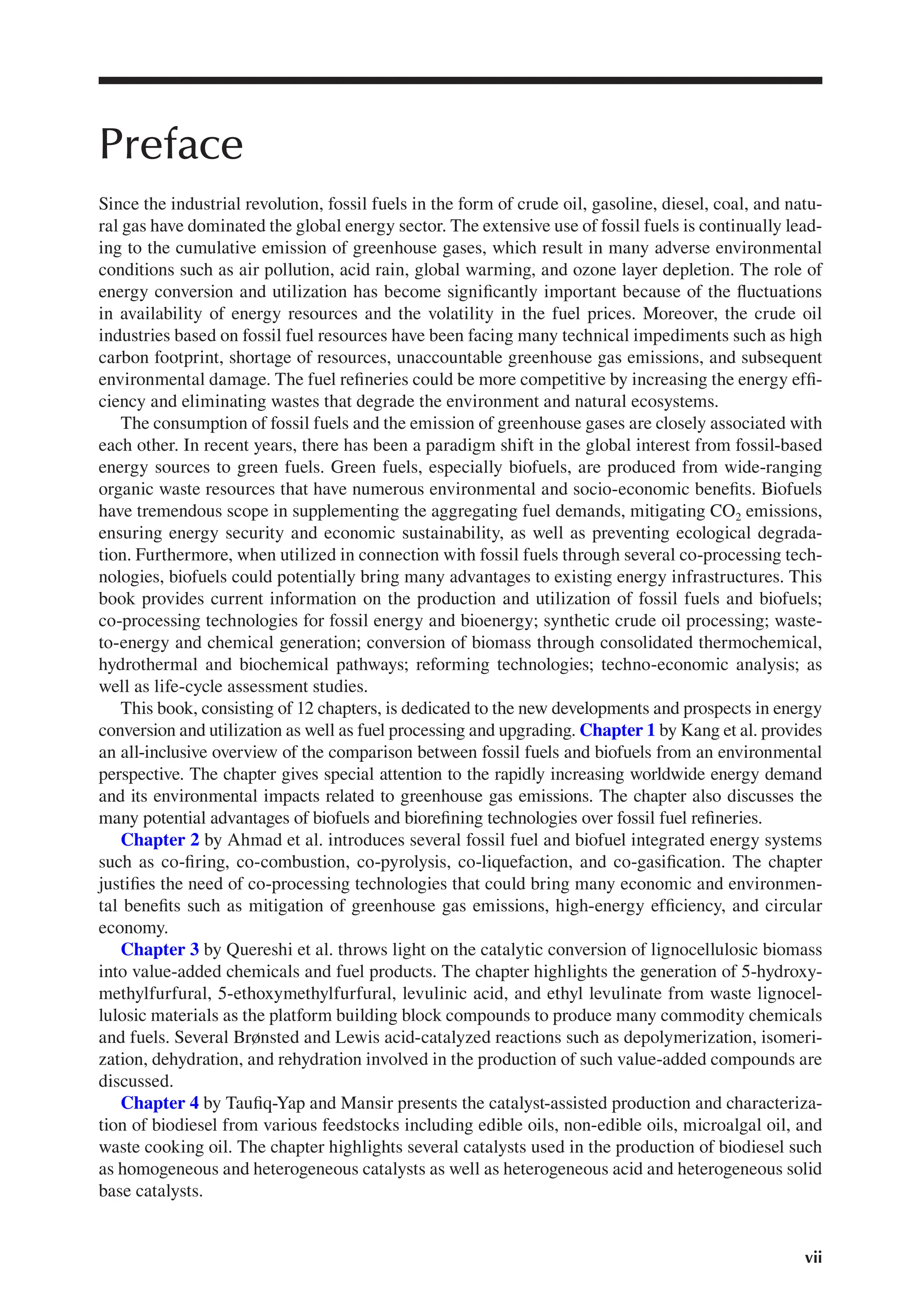


![Genus 304. Spirema,[344] Haeckel, 1881, Prodromus, p. 464.
Definition.—L i t h e l i d a with simple, spherical or subspherical,
medullary shell, and lentelliptical or subspherical, spirally constructed
cortical shell; surface smooth or thorny, without radial spines.
The genus Spirema begins the series of the Spiremida, or of those
Lithelida in which the medullary shell presents a simple latticed
sphere or ellipsoid, never composed of a double, trizonal or
Larnacilla-shaped shell. In the present state of our knowledge we
cannot say whether this simple medullary shell be a primary
formation, or effected by secondary means, by reduction of a double
Larnacilla-shaped medullary shell, which is constantly found in the
Larcospirida. The species of this genus (as of all Lithelida) are
difficult to distinguish, are transformistic, and incline very much to
variations and abnormalities. The spiral may be simple or double.
Subgenus 1. Spiremarium, Haeckel.
Definition.—Spiral convolutions of the cortical shell simple.
1. Spirema lentellipsis, n. sp.
Cortical shell lentelliptical, with smooth surface; proportion of its
three dimensive axes = 4 : 5 : 6. In the median plane are visible
four perfect turnings of the simple spiral, the breadth of which
gradually increases towards the third convolution, finally decreasing;
the broadest (third) turning three times as broad as the simple
spherical medullary shell.](https://image.slidesharecdn.com/5251867-250618183311-79809432/75/Fuel-Processing-And-Energy-Utilization-Sonil-Nanda-Prakash-Kumar-Sarangi-63-2048.jpg)


![second convolution is four times as great as that of the first
convolution and the simple spherical medullary shell.
Dimensions.—Length of the shell 0.22, breadth 0.21, height 0.2;
medullary shell 0.02.
Habitat.—Tropical Atlantic, off Sierra Leone, Station 348, depth
(2450) fathoms.
Genus 305. Lithelius,[345] Haeckel, 1862, Monogr. d. Radiol., p. 519.
Definition.—L i t h e l i d a with simple, spherical or subspherical,
medullary shell, and lentelliptical or subspherical, spirally constructed
cortical shell; surface covered with numerous, simple or branched,
radial spines.
The genus Lithelius, founded by me in 1862, and represented by two
Mediterranean species, was at that time the only known form of this
family, which now contains six genera and twenty-seven species. It
differs from the foregoing Spirema in the possession of numerous
radial spines on the surface. These may be either simple or
branched. The spiral may be simple or double, and according to this
latter modification we distinguish two different subgenera.
Subgenus 1. Lithospira, Haeckel.
Definition.—Spiral convolutions of the cortical shell simple.
1. Lithelius spiralis, Haeckel.](https://image.slidesharecdn.com/5251867-250618183311-79809432/75/Fuel-Processing-And-Energy-Utilization-Sonil-Nanda-Prakash-Kumar-Sarangi-66-2048.jpg)


![the third turn is four times as broad as the simple spherical
medullary shell.
Dimensions.—Length of the cortical shell (with three spiral
convolutions) 0.18, breadth 0.12; diameter of the medullary shell
0.01.
Habitat.—North Atlantic, Færöe Channel, surface, John Murray.
Subfamily 2. Larcospirida, Haeckel.
Definition.—L i t h e l i d a with double, trizonal, or Larnacilla-shaped
medullary shell.
Genus 306. Larcospira,[346] n. gen.
Definition.—L i t h e l i d a with double, trizonal, or Larnacilla-shaped
medullary shell; cortical shell subspherical or lentelliptical,
constructed of a simple or double spiral of the transverse girdle (or
primary cortical girdle); the spiral lamella revolving around the
principal axis.
The genus Larcospira begins the interesting series of the
Larcospirida, or of those Lithelida in which the medullary shell is
formed by a trizonal or Larnacilla-shaped lattice-shell, and the
cortical shell by spiral turnings of one of the three girdles, which
compose the cortical shell of the Pylonida. In Larcospira, as the
oldest and most simple form of Larcospirida, the spiral is formed by
the transverse girdle, or the first girdle of the Diplozonaria, the only
cortical girdle of Amphipyle. If in this genus one of both wings of the](https://image.slidesharecdn.com/5251867-250618183311-79809432/75/Fuel-Processing-And-Energy-Utilization-Sonil-Nanda-Prakash-Kumar-Sarangi-70-2048.jpg)


![Definition.—Spiral convolutions or turns of the cortical shell double;
both wings of the transverse girdle turning around the principal axis.
4. Larcospira oliva, n. sp.
Cortical shell with smooth surface, six times as long as the
lentelliptical medullary shell. Perimeter of the lateral plane elliptical,
one and a fourth times as long as broad, without constrictions. Both
lateral wings of the transverse girdle turn round one another and
form one and a half to two double spiral turns.
Dimensions.—Length of the cortical shell 0.25, breadth 0.2; length of
the medullary shell 0.04, breadth 0.035.
Habitat.—Antarctic Ocean, Station 157, depth 1950 fathoms.
Genus 307. Pylospira,[347] n. gen.
Definition.—L i t h e l i d a with double, trizonal or Larnacilla-shaped
medullary shell; cortical shell subspherical or lentelliptical,
constructed of a single or double spiral of the lateral girdle (or
second cortical girdle); the spiral lamella revolving round the sagittal
axis.
The genus Pylospira follows after Larcospira as the second genus of
Larcospirida; but in this latter the spiral of the cortical shell is formed
by the transverse girdle (or the first lattice-girdle of the
Diplozonaria), whilst in Pylospira it is produced by the lateral girdle,
or the second lattice-girdle of that group. Therefore Pylospira may
be derived phylogenetically from Tetrapyle in the same manner as
Larcospira from Amphipyle. Whilst in this latter the first cause of the](https://image.slidesharecdn.com/5251867-250618183311-79809432/75/Fuel-Processing-And-Energy-Utilization-Sonil-Nanda-Prakash-Kumar-Sarangi-73-2048.jpg)


![Habitat.—Indian Ocean, Madagascar, Rabbe, surface.
Genus 308. Tholospira,[348] n. gen.
Definition.—L i t h e l i d a with double, trizonal or Larnacilla-shaped
medullary shell; cortical shell subspherical or lentelliptical
constructed of a simple or double spiral of the sagittal girdle (or third
cortical girdle); the spiral lamella revolving around the transverse
axis.
The genus Tholospira represents the third genus of Larcospirida.
Whilst the spiral growth of the cortical shell is produced in Larcospira
by the first (transverse) girdle of the Diplozonaria, in Pylospira by the
second (lateral) girdle, in Tholospira it is effected by the third or
sagittal girdle, which we found complete in Pylonium. If in this genus
one wing of the sagittal girdle overgrow the other remaining one and
turn around the transverse axis, we get Tholospirema, the first
subgenus of our genus, with simple spiral; but if afterwards the
second wing follow the example of the first, and overgrow it from
the other side, we get Tholospironium, with double spiral.
Subgenus 1. Tholospirema, Haeckel.
Definition.—Spiral convolutions or turns of the cortical shell simple,
only one single wing of the sagittal girdle turning around the
transverse axis.
1. Tholospira nautiloides, n. sp.](https://image.slidesharecdn.com/5251867-250618183311-79809432/75/Fuel-Processing-And-Energy-Utilization-Sonil-Nanda-Prakash-Kumar-Sarangi-76-2048.jpg)


