Download to read offline

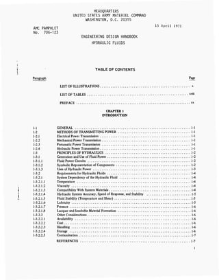

![AMCP 706-123
components and hydraulic fluid, must be designed
as an integral system.
This chapter is devoted to a discussion of the me-
chanical components of the system and their interrela-
tionship with the hydraulic fluid. No attempt is made
to provide a comprehensive discussion of equipment
design. For this, the reader is referred to any one of
several works devoted to the subject (Refs. 1, 2, 3,
4, 5).
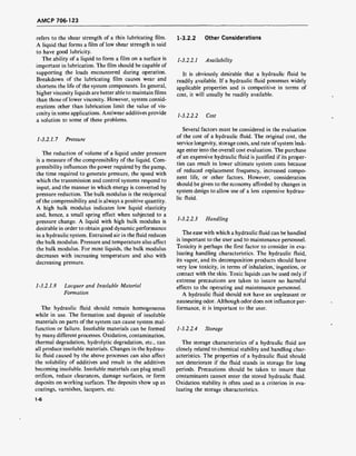
To illustrate the manner in which system compo-
nents are integrated into a hydraulic circuit, consider
the circuit illustrated in Fig. 2-1. This is a rotary liquid
motor circuit which produces constant torque. To do
so, a constant hydraulic pressure must be maintained
on the motor. This condition is achieved by using a
pressure regulator valve upstream of the motor. Con-
stant pressure could also be obtained by using a pres-
sure-compensated, variable-displacement pump.
r^>
=y Ig
r
i—i
<►—(I
E]wc==l
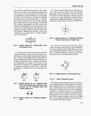
Fig. 2-1. Rotary MotorCircuit Which Produces Constant
Torque [Shown are: (a) hydraulic pump and
drive motor, (b) reservoir and strainer,
(c) manually operated control valve, (d) pres-
sure regulator valve, (e) check valve, (f) hy-
draulic motor, and (g) pressure relief valve]
The circuit of Fig. 2-1 contains all six of the basic
components mentioned in Chapter 1. The pump (a),
driven by an electric motor, serves as the source of fluid
energy. The fixed-displacement hydraulic motor (f)
converts hydraulic energy into mechanical energy. Hy-
draulic piping is provided between the system compo-
nents. Directional controls are provided by the manu-
ally actuated control valve (c) and the check valve (e).
The pressure regulator (d) and the relief valve (g) pro-
vide pressure control. A fluid reservoir (b) serves both
for storage and as a system vent location. Less obvious
is the hydraulic fluid without which the system could
not perform a single useful function.
The design of a hydraulic system encompasses many
factors. Given a particular power transmission or con-
trol problem, the designer must first determine what
type of components will accomplish the desired objec-
tive. A conceptual layout of the system is then followed
by engineering analysis to determine the necessary size,
configuration, and details of the hardware. Suitable
materials must be selected for component construction,
and engineering drawings must be prepared. Underly-
ing each of these steps is the nebulous factor commonly
referred to as good engineering practice. This entails a
knowledge, usually acquired through experience, of the
features which constitute good design practice, i.e.,
those factors which cannot be readily subjected to pre-
cise mathematical and engineering analysis.
The equations with which the designer constructs a
mathematical model of a hydraulic system are, in gen-
eral, nonlinear differential equations, frequently of sec-
ond or higher order. Such equations usually require
numerical solutions and, hence, digital and analog
computers have become valuable aids in the design of
hydraulic systems. A thorough engineering analysis be-
gins with the specification of certain parameters which
the system must satisfy-such as force or load require-
ments, stability, speed of response, accuracy, and reso-
lution. The mathematical model is then manipulated
until the desired specifications are met on paper. The
resulting information can be used in system specifica-
tion and fabrication.
However, a detailed computer solution of the equa-
tions which describe the system does not always result
in a design which performs as predicted by the analysis.
It is frequently possible, using the appropriate approxi-
mations and sound engineering practice, to design a
system based upon hand computations which will per-
form as well as, or better than, one based upon a de-
tailed computer analysis. Usually, it is desirable to use
a preliminary hand-calculated analysis to optimize a
subsequent, more detailed computer analysis. Math-
ematical techniques in the form of computer programs
are now available, which facilitate detailed analysis by
relieving the designer of the necessity of developing
routines for the solution of complex nonlinear equa-
tions.
Merritt (Ref. 4) distinguishes between two types of
parameters involved in hydraulic system design. A
2-2](https://image.slidesharecdn.com/884519-170327080602/85/Fluid-mechanics-material-32-320.jpg)
![AMCP 706-123
hard parameter is defined as a physical quantity which
can be measured with good precision and which re-
mains essentially constant. A soft parameter, on the
other hand, is a quantity which is difficult to measure
or compute and, for a given system, can be determined
only within a range of values. The most important
design features of a system should be based upon hard
parameters, if possible. Merritt points out that an im-
portant part of sound engineering design practice is the
ability to distinguish between hard and soft parameters.
2-2 PUMPS
A hydraulic pump is a device used to impart motion
to a liquid and thereby convert mechanical energy to
hydraulic energy. It provides the force required to
transmit power. Pumps are rated in terms of flow and
pressure. The flow rating (volumetric output) is the
amount of liquid which can be delivered by the pump
per unit time at a specified speed. A pump does not
produce pressure. The pressure developed at the outlet
depends on the resistance to flow in the circuit.
Pumps are classified according to configuration or
operating characteristics. One obvious classification is
that of rotary or reciprocating pumps. Rotary pumps
utilize a rotating assembly to transfer the fluid from the
inlet to the outlet and to impart motion. Rotary pumps
can be further classified as gear, vane, or rotating piston
pumps. Reciprocating pumps employ a plunger or pis-
ton to impart motion to the fluid.
Pumps can also be classified as positive- or non-
positive-displacement devices. Positive-displacement
pumps move a definite amount of fluid during each
stroke or revolution. They are most frequently used in
hydraulic systems. Nonpositive-displacement, or hy-
drodynamic, pumps provide continuous flow. They are
primarily low-pressure devices with high volumetric
output.
Positive-displacement pumps can be of either fixed
or variable displacement. The output of a fixed-dis-
placement pump is constant at a given pump speed.
The output of a variable-displacement pump can be
changed by adjusting the geometry of the displacement
chamber.
2-2.1 GEAR PUMPS
Gear pumps are the most widely used pumps for
hydraulic systems. They are available in a wide range
of flow and pressure ratings. The drive and gears are
the only moving parts.
2-2.1.1 External Gear Pumps
In external gear pumps, two or more gears mesh with
minimum clearance. The gear motion generates a suc-
tion at the inlet, which causes fluid to be drawn into the
pump housing. The liquid is drawn through the pump
and is displaced as the teeth mesh on the outlet side.
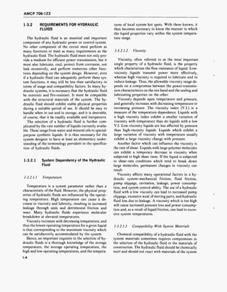
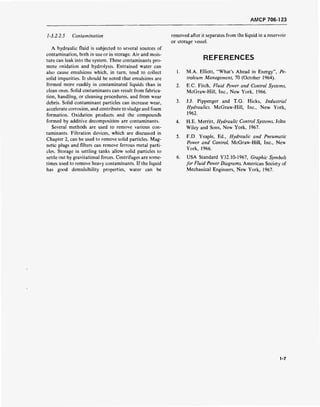
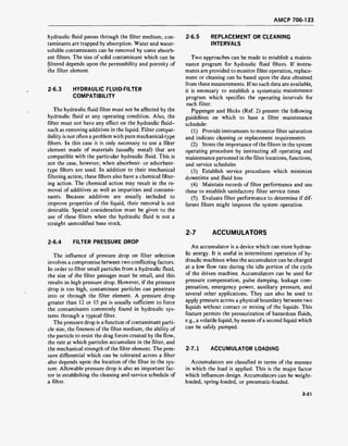
(1) Spur gear pumps: A spur gear rotary hydraulic
pump is illustrated in Fig. 2-2. The two gears rotate in
opposite directions and transfer liquid from the inlet to
the outlet through the volume between the teeth and
the housing. The output depends on tooth width and
depth, and is largest for a minimum number of teeth.
Involute teeth with a pressure angle of 20-30 deg are
common in spur gear pumps. However, progressive-
contact and edge-contact gears are sometimes used to
avoid the severe loads generated by liquid trapped be-
tween the contact points of the meshed involute teeth.
Fig. 2-2. Spur Gear Rotary Hydraulic Pump
4*
[From: H. E. Merrit, Hydraulic Control Systems.
Used by permission of John Wiley and Sons]
The spur gear pump is a fixed-displacement pump.
Output at a given speed decreases slightly with pres-
sure. Typical operating characteristics are shown in
Fig. 2-3. These curves are for a spur gear pump operat-
ing with a liquid of constant viscosity. This viscosity
effect illustrates one of the ways in which the liquid
influences the specification of system components.
'Superscript numbers refer to References at the end of each
chapter.
2-3](https://image.slidesharecdn.com/884519-170327080602/85/Fluid-mechanics-material-33-320.jpg)
![AMCP 706-123
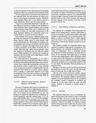
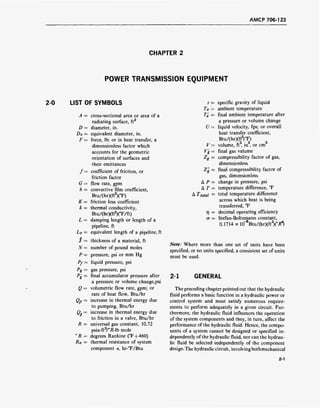
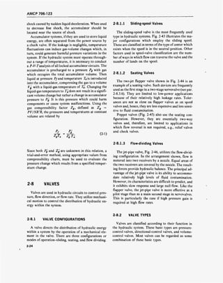
Fig. 2-3.
60 120 180 210
DISCHARGE PRESSURE, psi
300
Typical Operating Characteristic Curves
for a Spur Gear Rotary Hydraulic Pump
[From: Pippenger and Hicks, Industrial Hydraulics.
Used by permission of McGraw-Hill, Inc.]
of both gears. The contact point of the gear teeth forms
a seal, as does the small tip clearance at the crescent.
This pump is generally used for low output applications
at pressures below 1,000 psi.
DISCHARGE
DRIVE
GEAR
SUCTION
INTERNAL GEAR
OR ROTOR
CASING
CRESCENT
Fig. 2-4. Crescent Seal Internal Gear Hydraulic
Pump [Shown are: crescent C, gear teeth
T, and drive gear G ]
2
[From: Pippenger and Hicks, Industrial Hydraulics.
Used by permission of McGraw-Hill, Inc.]
(2) Helical gear pumps: A variation of the external
gear spur gear pump is the helical gear pump. The fact
that several teeth are engaged simultaneously allows
the helical gear pump to carry larger loads at high
speeds than can the spur gear pump. Operation is simi-
lar to that of the spur gear pump, but with less noise
and usually smaller flow pulsations. Because of the
helical gear configuration, end thrusts are developed by
helical gears. These forces act in opposite directions on
the drive and driven gears.
(3) Herringbone gear pumps: Another variation of
the external gear pump incorporates herringbone gears.
Like all gear pumps, the herringbone device is a con-
stant displacement pump. It is generally available for
pressures up to about 2,000 psi but some models are
rated at over 3,000 psi.
2-2.1.2 Internal Gear Pumps
There are two types of internal gear pumps: the cres-
cent seal pump and the geroter pump.
(1) Crescent seal pumps: The crescent seal pump
consists of an inner and outer gear separated by a cres-
cent-shaped seal (Fig. 2-4). The gears rotate the same
direction, with the inner gear rotating at a higher speed.
The liquid is drawn into the pump at the point where
the gear teeth begin to separate and is carried to the
outlet in the space between the crescent and the teeth
(2) Gerotor pumps: The gerotor pump consists of a
pair of gears which are always in sliding contact (Fig.
2-5). The larger internal gear has one more tooth than
the external gear. Both gears rotate in the same direc-
tion. Liquid is drawn into the chamber where the teeth
are separating, and is ejected when the teeth again start
to mesh. The seal is provided by the sliding contact.
Gerotor pumps are restricted to low-pressure opera-
tion because of the loads generated by the hydraulic
unbalance.
OUTER
ELEMENT
INNER
ELEMENT
DISCHARGE
SIDE
INTAKE
SIDE
DECREASING
POCKETS
INCREASING
POCKETS
Fig. 2-5. Gerotor Internal Gear Hydraulic Pump
[From: Pippenger and Hicks, Industrial Hydraulics.
Used by permission of McGraw-Hill, Inc.]
2-4](https://image.slidesharecdn.com/884519-170327080602/85/Fluid-mechanics-material-34-320.jpg)
![AMCP 706-123
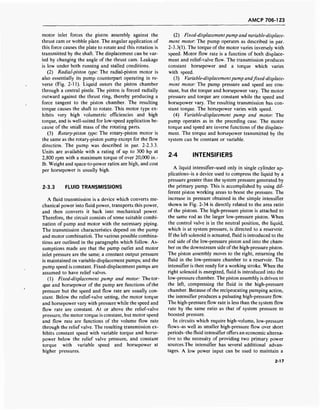
2-2.2 VANE PUMPS 2-2.2.1 Unbalanced Vane Pumps
Vane pumps consist of a rotor mounted in a cam-
shaped housing. The rotor is provided with radial slots
which accommodate vanes. As the internal assembly
rotates, the vanes are forced radially outward against
the housing by centrifugal force sometimes assisted by
springs. Vane pumps can operate at speeds up to 2,000
rpm and are available in pressure ratings to 2,500 psi.
Their simple construction results in a high degree of
reliability and easy maintenance. They are relatively
low in cost and exhibit long operating life partially due
to the fact that vane wear is accommodated by the
radial motion of the vanes. They have comparatively
high volumetric and overall efficiencies, and are availa-
ble in a wide range of output ratings. Typical operating
characteristic curves of a vane pump are shown in
Fig. 2-6.
Delivery(gpm)
InputPower(hp)
3ooooooooo<
i—r—l—t—■ |
Volumetric efficiency'
J l—1—1—
90
80 ■£
70 S
60 a
50 "£,
40 §j
50 5
20 ui
10
s^"Over-oil efficiency
/
—1
^ueiivery
jnpur power
1 i [
3 400 800 1200 1600 2C
Pressure (psi)
KM
Fi$>. 2-6 . Typical Operating Characteristic Curves for
a Vane Hydraulic Pump
[From: Fluid Power Issue; Machine Design. Used by
permission of Penton Publishing Co.]
Operating limitations of vane pumps are imposed by
vane tip speed, bearing loads, and cavitation. The force
exerted by the vanes against the housing can be con-
trolled by using dual vanes, i.e., two vanes in each slot.
Each of the dual vanes has a smaller contact area than
a single vane. The dual vane design also provides a
better seal between the vanes and the housing.
Vane pumps exhibit a good tolerance to liquid con-
tamination. They are generally used with petroleum-
base or Military Specification hydraulic fluids in mo-
bile operations and with petroleum or fire-resistant
hydraulic fluids in stationary applications. Discharge
pulsations can sometimes constitute a problem if high
response is desired.
In the unbalanced vane pump, the rotor and cam
housing are eccentric (Fig. 2-7). The pump suction is
generated in the region where the vanes begin to move
outward. The liquid is carried around the rotor by the
vanes, which form a seal with the housing and the end
plates, and it is discharged as the vanes are forced back
into the rotor slots by the eccentric housing.
Springs-
Shaft
/Tsf / ^^^
j-'.'y v/ Afct /A v/A
Vanes
Fig. 2-7. Unbalanced Vane Hydraulic Pump
[From: H. E. Merrit, Hydraulic Control Systems.
Used by permission of John Wiley and Sons]
Unbalanced vane pumps can be either fixed- or vari-
able-displacement pumps. In the fixed-displacement
pump the rotor-housing eccentricity is constant and,
hence, the displacement volume is fixed. A constant
volume of fluid is discharged during each revolution of
the rotor. Variable displacement can be provided if the
housing can be moved with respect to the rotor. This
movement changes the eccentricity and, therefore, the
displacement.
In addition to sliding vanes, rolling vanes and
swinging vanes are also available in unbalanced vane
pumps (Fig. 2-8). Each of these variations is hydro-
statically unbalanced. This unbalance causes high bearing
(A) (B)
Fig. 2-8. Vane-type Hydraulic Pumps and Motors
(A) Rolling Vane, and (B) Swinging Vane
4
[From: H. E. Merrit, Hydraulic Control Systems.
Used by permission of John Wiley and Sons]
2-5](https://image.slidesharecdn.com/884519-170327080602/85/Fluid-mechanics-material-35-320.jpg)
![AMCP 706-123
loads and generally limits the application of unbalanced
vane pumps to operating pressures less than about 1,500
psi (Ref. 4).
2-2.2.2 Balanced Vane Pumps
Hydraulic balance is achieved in the balanced vane
pump in which the rotor is in an elliptic housing (Fig.
2-9). This configuration creates two diametrically-
opposed displacement volumes. The two high-pressure
zones balance the forces on the rotor shaft. In many
such units no springs are provided to assist the outward
motion of the vanes. This condition restricts operation
to speeds above a minimum at which the centrifugal
force is sufficient to hold the vanes against the housing.
Other designs utilize springs for start-up and low-speed
operation. Balanced vane pumps are necessarily fixed-
displacement machines.
2-2.3 PISTON PUMPS
The applications for which the piston pump is well-
suited are determined by its two principal advantages-
high-pressure capability and high volumetric effi-
ciency. In addition, the piston pump can operate at
speeds over 2,000 rpm; is available in a wide range of
output ratings; and provides a compact, lightweight
unit for high power applications, low noise level when
flow path is linear, and better system economy in the
higher power ranges (above 20 hp).
Piston pumps are classified by the motion of the
piston relative to the drive shaft. There are three
categories-axial, radial, or rotating.
ROTOR
DISCHARGE
PORT
B
SUCTION
PORT
A
CASING
INLET OR OUTLET PORT BARREL PISTON
DRAIN PORT
VANE
Fig. 2-?. Balanced Vane Hydraulic Pump
2-2.3.1 Axial-piston Pumps
In the axial-piston pump, rotary shaft motion is con-
verted to axial reciprocating motion which drives the
piston. Most axial-piston pumps are multi-piston de-
signs and utilize check valves or port plates to direct
liquid flow from inlet to discharge. Output can be con-
trolled by manual, mechanical, or pressure-compen-
sated controls. An axial-piston pump is shown in Fig.
2-10. Rotary drive motion is converted to reciprocat-
ing, axial piston motion by means of the thrust cam, or
wobble plate, mounted on the drive shaft. Variable-
displacement volume is provided by the internal valv-
ing arrangement. Axial-piston pumps are available
with output ratings of over 100 gpm, and some types
are rated at pressures above 5,000 psi.
KEEPER PLATE
PISTON SHOE
THRUST CAM
VALVE HEAD
BEARING
VALVE HEAD' SHAFT BEARING
MOUNTING FLANGE
INLET OR OUTLET PORT BARREL BEARING
Fig. 2-10. Axial-piston Hydraulic Pump
[From: H. E. Merrit, Hydraulic Control Systems?Jsed by permission of John Wiley and Sons.]
2-6](https://image.slidesharecdn.com/884519-170327080602/85/Fluid-mechanics-material-36-320.jpg)
![AMCP 706-123
2-2.3.2 Radial-piston Pumps
In a radial-piston pump, the pistons move perpen-
dicularly to the shaft centerline. Two basic types of
radial-piston pumps are available. One uses cylindrical-
shaped pistons and the other uses spherical-shaped pis-
tons. In the pump shown in Fig. 2-11, the pistons move
in a rotating cylinder block and are forced outward by
centrifugal force. In Fig. 2-11, only one piston is
shown (in four positions); however, most pumps are
multi-piston.
CYLINDER BLOCK
SLIDE BLOCK
PINTLE
(STATIONARY)
ROTOR
SLIDE BLOCK *^^~ -^Zt VlSTON
C0MTR0L
Fig. 2-11. Radial-piston Hydraulic Pump With Ro-
tating Piston Housing [One piston is shown
at four positions-A, B, C, and D]
2
[From: Pippenger and Hicks, Industrial Hydraulics.
Used by permission of McGraw-Hill, Inc.]
A radial-piston pump which employs spherical pis-
tons is shown in Fig. 2-12. The pistons move radially
in a rotating cylinder block. They are forced against the
eccentric housing by centrifugal force. Liquid porting
is achieved by means of a pintle. The displacement can
be varied by changing the eccentricity of the housing.
Pumps of this type operate at high speeds, ranging from
about 7,000 rpm for a 35-gpm unit to nearly 20,000
rpm for pumps with 2- to 8-gpm output ratings (Ref.
1). One advantage of the spherical-piston pump is a
relatively high power-to-weight ratio.
Fig. 2-12. Radial-piston Hydraulic Pump With Spher-
ical Pistons
[From: E. C. Fitch, Fluid Power and Control Systems1
.
Used by permission of McGraw-Hill, Inc.]
2-2.3.3 Rotating Piston Pumps
The rotating piston pump (sometimes called the ro-
tary abutment pump) has three parallel synchronous
shafts (Fig. 2-13). Piston rotors are mounted on the
outside shafts and seal dynamically against the cylin-
drical housing. The rotor mounted on the center shaft
forms an abutment valve. The rims of the piston rotors
pass through a bucket cut in the center rotor. Except
when the rim is meshed with the abutment valve, a
rolling-contact seal is maintained between the rotors.
Liquid is drawn into the right cylinder shown in Fig.
2-13, pumped through to the left cylinder, and dis-
charged by the left piston. Pumps of this type are avail-
able with ratings to over 150 gpm at 1,500 psi.
Fig. 2-13. Rotating Piston Hydraulic Pump [Shown are two rotating pistons P, and P2, and rotating abutment V.]
4
[From: H. E. Merrit, Hydraulic Control Systems. Used by permission of John Wiley and Sons]
2-7](https://image.slidesharecdn.com/884519-170327080602/85/Fluid-mechanics-material-37-320.jpg)
![AMCP 706-123
2-2.4 SCREW PUMPS
A screw pump is an axial-flow gear pump. Fig. 2-14
shows a two-rotor screw pump with helical gears. Liq-
uid is introduced at the two ends and discharged at the
center. The seal is formed by the contact of the two
gears at the intersection of their addenda and by the
small clearance between the gears and the pump hous-
ing. In pumps employing double helical gears, as shown
in Fig. 2-14, the thrust loads are balanced. This design
is frequently employed in large pumps. Screw pumps
are especially applicable where quiet operation is essen-
tial. In screw pumps, the gears must be in contact at the
intersection of their addenda. This contact plus the
minimum clearance at the outside diameter of the
gears, provides a series of sealed chambers along the
length of the screws. Screw pumps can also be arranged
with three rotors. The center gear is the driver, and no
timing gears are necessary.
SIDE VIEW
INTAKE
Fig. 2-14. Two-rotor Screw Hydraulic Pump With
Helical Gears
2
[From: Pippenger and Hicks, Industrial Hydraulics.
Used by permission of McGraw-Hill, Inc.]
2-2.5 BELLOWS PUMPS
A sketch of a typical bellows pump is shown in Fig.
2-15. The bellows is constructed of thin flexible metals
or elastic nonmetals. Compression of the bellows by the
actuator provides the pumping action. Liquid flow is
controlled by check valves at the inlet and outlet ports.
Bellows pumps are not generally used in hydraulic sys-
tems and find only limited applications in other fields.
One area of application has been the medical field
where they have the advantage of simple construction
and are easily fabricated of inexpensive disposable
materials. Bellows pumps also are very effective pumps
for liquids that are contaminated with solid particle
material, and for abrasive slurries. There are no small
clearance areas for the particles to damage or close.
BELLOWS -
LIQUID
- OUT«-
=0
ACTUATOR
GSm-m
LIQUID
< - IN
Fig. 2-15. Typical Bellows Pump
2-2.6 DIAPHRAGM PUMPS
A sketch of a typical diaphragm pump is shown in
Fig. 2-16. The diaphragm is a flexible disk attached
about its circumference to the pump housing. The ac-
tuator moves the diaphragm in a reciprocating motion
which provides the pumping action. Diaphragms can
be flexible sheets of metal or elastic nonmetals. Liquid
flow is controlled by check valves at the inlet and outlet
ports. Diaphragm pumps are primarily low pressure,
pulsating flow pumps and are not often used for hy-
draulic power sources. Diaphragm pumps are occa-
sionally used as hydraulic power sources where a
remote pump is required-such as in high-temperature
or corrosive environments. The valve head, containing
the inlet and outlet valves, can be located in the hostile
environment and the diaphragm unit located in a
remote place. One of the most common uses of dia-
phragm pumps is the fuel pump on automobiles.
Diaphragm pump advantages include simple con-
struction, no lubrication problems, high volumetric ef-
ficiency, and insensitivity to contamination. Major
disadvantages are the low pressures obtainable, pulsat-
ing flow, and low flow rates.
2-8](https://image.slidesharecdn.com/884519-170327080602/85/Fluid-mechanics-material-38-320.jpg)
![AMCP 706-123
— DIAPHRAGM
ACTUATOR
DIAPHRAGM
2-3.1 LINEAR ACTUATORS
2-2.7
Fig. 2-16. Typical Diaphragm Pump
CONNECTION BETWEEN PUMP AND
DRIVE MOTOR
The physical connection between the hydraulic
pump and its drive motor is not technically a hydraulic
component. However, it is an important part of the
hydraulic system, and in many cases, may be the weak-
est link in the power train. There are a number of
methods for coupling the drive motor output shaft to
the hydraulic pump input shaft. Some of the more com-
mon methods are keys and pins, flexible couplings,
universal joints, clutches, and splines. The most fre-
quently used connector in hydraulic systems is the
spline.
Splines offer the advantage of being able to transmit
the maximum load with the smallest coupling diame-
ter. In addition, they are self-centering, tend to equally
distribute the load, and are simple to manufacture with
standard gear-cutting equipment. Their major disad-
vantage is the problem of wear. Even the best designed
splines are subject to relative motion of the parts and
are difficult to lubricate.
2-3 ACTUATORS
An actuator is a device for converting hydraulic en-
ergy to mechanical energy, and thus has a function
opposite that of a pump. An actuator, or fluid motor,
can be used to produce linear, rotary, or oscillatory
motion.
A linear actuator or hydraulic cylinder is a fluid
motor that generates linear motion. Various types are
widely used in hydraulic systems because of their high
force capability, ease of speed control, and high power
output for a given size and weight. They are especially
suitable for control systems due to their high mechani-
cal stiffness and speed of response.
2-3.1.1 Classification of Linear Actuators
The many types of linear actuators which are availa-
ble give rise to several criteria for classification.
(1) Rotating or nonrotating: In a rotating actuator
the cylinder, rod, and piston can rotate. In many ap-
plications, such as on rotary machine tools, this
feature is necessary to allow unrestricted motion of
the piston rod. Such an actuator is illustrated in Fig.
2-17. In order to permit stationary mounting of the
fluid connections, a rotating seal is required.
The nonrotating linear actuator, in which the cylin-
der is not free to rotate, is the most widely used fluid
motor.
Fig. 2-17. Rotating Linear Actuator
[From: E. C. Fitch, Fluid Power and Control Systems*.
Used by permission of McGraw-Hill, Inc.]
(2) Piston or plunger: The piston and rod assembly
in a piston-type linear actuator serves to divide the
cylinder volume into two separate chambers. The pis-
ton and attached sealing devices provide the seal be-
tween the two chambers. The rotating actuator shown
in Fig. 2-17 is a piston actuator.
In a plunger-type there is no piston. The end of the
reciprocating rod serves as the working face (see Fig.
2-18). The only seal provided is at the point where the
plunger passes through the end of the cylinder. An
external force is required to move the plunger into
the cylinder.
Both types provide a longer stroke and permit the
use of the highest pressure.
2-9](https://image.slidesharecdn.com/884519-170327080602/85/Fluid-mechanics-material-39-320.jpg)
![AMCP 706-123
Fig. 2-18. Plunger-type Linear Actuator
[From: E. C. Fitch, Fluid Power and Control Systems.
Used by permission of McGraw-Hill, Inc.]
(3) Rod classification: Linear actuators can also be
classified as to rod type. A cylinder with one piston rod
is termed a single-rod actuator. The actuators shown in
Figs. 2-17 and 2-18 are single-rod actuators. A double-
rod actuator has piston rods extending from both ends
of the cylinder. A telescoping rod consists of a series of
nested rods which provide a long extension (Fig. 2-19).
Such rods are useful for applications requiring a long
stroke but with only limited space available for the
unextended rod. A positional rod is used where the
stroke is split up into two or more portions. The cylin-
der can be actuated to any one of the positions.
J RAISE
LOWER
Fig. 2-19. Telescoping Linear Actuator
[From: Pippenger and Hicks, Industrial Hydraulics.
Used by permission of McGraw-Hill, Inc.]
(4) Cylinder action: The type of cylinder action is
important in the specification of linear actuators. An
actuator can be single-acting or double-acting. The sin-
gle-acting type can move the piston rod in only one
direction by the application of hydraulic pressure. A
plunger-type actuator, discussed in subparagraph 2-
3.1.1(2), is a single-acting actuator. In the double-
acting actuator, liquid pressure can be applied to either
side of the piston, thereby providing a hydraulic force
in both directions (Fig. 2-20). Double-acting actuators
are also shown in Figs. 2-17 and 2-19. Springs, external
forces, or a combination of both can be used to assist
return of the piston rod or plunger.
DOUBLE-ACTING CIRCUIT
tTHRUST IN BOTH 01RECTI0NSI
PACKED
GLAND
Fig. 2-20. Double-acting Linear Actuator
2
[From: Pippenger and Hicks, Industrial Hydraulics.
Used by permission of McGraw-Hill, Inc.]
(5) Single, tandem, and dual actuators.Yet another
means of actuator classification is its assembly. Assem-
blies of actuators can be designed to obtain various
types of cylinder operation. A tandem actuator is one
in which two or more piston and rod combinations are
assembled as a rigid unit with all pistons mounted on
a single rod. Fig. 2-21 shows a stepped-tandem
actuator-two pistons of different sizes mounted on one
rod. Such actuators can be designed to obtain, for ex-
ample, a low-force, high-speed action followed by a
high-force, low-speed action. Tandem pistons can also
be designed to provide a large working area (and thus
large forces for a given pressure) for a small cylinder
diameter. The piston and rod assemblies of a dual ac-
tuator (Fig. 2-22) are not fastened together as in the
tandem actuator. In most dual actuator designs, a given
piston acts on another only in one direction. Tandem
and dual actuators are frequently used in hydro-
pneumatic systems where air is used as the power source
and a hydraulic fluid is used for control.
2-10](https://image.slidesharecdn.com/884519-170327080602/85/Fluid-mechanics-material-40-320.jpg)
![AMCP 706-123
'/////4&///A
wzzz 7///M
Fig. 2-21. Stepped-tandem Linear Actuator
[From: E. C. Fitch, Fluid Power and Control Systems.
Used by permission of McGraw-Hill, Inc.]
W////£y//77?,
XA &ZZ,
*--—>-
7/S//A V kl
Fig. 2-22. Dual Linear Actuator
[From: E. C. Fitch, Fluid Power and Control Systems.
Used by permission of McGraw-Hill, Inc.]
ports as the piston nears the end of the stroke (Fig.
2-23). A cushion-plunger attached to the piston enters
a cushion cylinder. This cushion plunger then blocks
the discharge port and traps liquid beneath the piston.
This liquid assists in the deceleration of the piston as
it approaches the cylinder head. A check valve allows
fluid to flow back into the cylinder at the start of the
return stroke. The rate of piston deceleration can be
controlled by designing the cushion plunger with a
proper taper. This taper then permits a gradual closing
of the discharge ports.
2-3.1.2 Mounting Configuration
One of the advantageous features of linear actuators
is the variety of ways in which they can be mounted in
a system. Several mounting arrangements are illus-
trated in Fig. 2-24.
2-3.1.3 Kinematics of Linear Actuators
(6) Cushioned or noncushioned type: In noncush-
ioned actuators, no provision is made for controlled
acceleration or deceleration of the piston assembly.
Therefore, such units have speed and inertia limitations
imposed at both ends of the stroke. Cushioned actua-
tors are designed to enable the kinetic energy of the
moving piston to be absorbed at the ends of the stroke
and thereby reduce peak pressures and forces. Cushion-
ing can be accomplished by blocking the discharge
The nature of the force provided by a linear actuator
depends on the kinematic linkage between the straight-
line output of the cylinder and the point at which the
force and motion are utilized. Because of the many
alternatives in the design of the linkage, the linear ac-
tuator can be used to produce rotary or oscillatory
motion as well as linear motion. The resultant ver-
satility of linear actuators is partially illustrated by the
applications shown in Fig. 2-25.
FLUID
INLET AND
OUTLET^
CUSHION
SEAL
PISTON
FLUID
INLET AND
OUTLET ROD
SCRAPER
HEAD
CYLINDER
BARREL
ROD '
PACKING
Fig. 2-23. Cushioned Double-acting Linear Actuator
2
[From: Pippenger and Hicks, Industrial Hydraulics. Used by permission of McGraw-Hill, Inc.]
2-11](https://image.slidesharecdn.com/884519-170327080602/85/Fluid-mechanics-material-41-320.jpg)
![AMCP 706-123
®—®
'— 1^ —*
SIDE FOOT MOUNT
l@ ©
fljjjrjfj ,„,i, ,.„l fg; -ij
CENTERLINE MOUNT
END FOOT MOUNT
IP (SI
omm
SIDE FLUSH MOUNT
m
p m
O
a as
REAR FLANGE MOUNT
wri
FRONT FLANGE MOUNT
-. Ö 0
o Ö
o o o
o o
rori
u a- is
o3) to]
1 unnrj
J
3
o o
SQUARE REAR FLANGE MOUNT SQUARE FRONT FLANGE MOUNT
ol l-l
CLEVIS MOUNT
0 ©
§> ©
3 rai®
FRONT TRUNNION MOUNT'
INTERMEDIATE TRUNNION AVAILABLE
c © DIS) <sT^
©
REAR TRUNNION MOUNT*
INTERMEDIATE TRUNNION AVAILABLE
©
TIE RODS EXTENDED BOTH ENDS
§ @
TIE RODS EXTENDED REAR END ONLY
JEM @
©
fr™ a i
TIE RODS EXTENDED FRONT END ONLY
HLSi Es HLBJTBASIC MOUNT DOUBLE-END CONSTRUCTION
AVAILABLE IN ANY MOUNT
Fig. 2-24. Mounting Arrangements for Linear Actuators
[From: Stewart and Storer, Fluid Power. Used by permission of Howard W. Sams and Co., Inc.]
2-12](https://image.slidesharecdn.com/884519-170327080602/85/Fluid-mechanics-material-42-320.jpg)
![AMCP 706-123
'/////////,
1 st class lever 2 nd class lever
' 7/7/77777//'
Toggle
Straight line motion
in two directions
V7777 0
Straight line
thrust reduced
"777,7777777777777?-
Straight push
3rd class lever
«
I
Straight line
motion
multiplied 2M
>///////
Horizontal
parallel motion
'/////// I K',,"//'////.
4 positive
positions with
two cylinders
Trammel
plate
Motion
transterred to
a distant ooint
77/77/7//,
Practically
continuous rotary
motion
/////////
Engine barring
7777777
77777777
Fast rotary
motion using
steep screw nut
Fig. 2-25. Applications of Linear Actuators
[From: E. C. Fitch, Fluid Power and Control Systems. Used by permission of McGraw-Hill, Inc.]
2-13](https://image.slidesharecdn.com/884519-170327080602/85/Fluid-mechanics-material-43-320.jpg)
![AMCP 706-123
2-3.2 ROTARY ACTUATORS OR MOTORS
As in the case of a linear actuator, the function of a
rotary actuator, or rotary fluid motor, is to convert
hydraulic energy into mechanical energy. Rotary mo-
tors are usually rated in terms of the theoretical torque
developed per 100 psi of inlet or differential pressure.
The actual running torque and the stalled torque may
be from 60 to 90 percent of the theoretical torque,
depending on the type of motor. The running volumet-
ric efficiency may vary from about 75 to 95 percent,
again depending on the particular motor. The highest
operating efficiency occurs near the rated torque
and speed.
The desirable features of the various types of rotary
motors include:
(1) The ability to suddenly start, stop, and reverse
without motor damage
(2) The ability to operate as a pump for braking
(3) A higher horsepower-to-weight ratio than any
other conventional power source
(4) An infinitely-variable speed range
(5) The ability to operate through zero speed for
overrunning loads
(6) The ability to accommodate contaminants in
the fluid.
Rotary fluid motors are essentially rotary pumps
operating in reverse. The mechanical characteristics of
a particular rotary motor are nearly identical with
those of the corresponding pump.
2-3.2.1 Gear Motors
Gear motors, like gear pumps, can be classified as
external or internal gear units. Also like gear pumps,
they are fixed-displacement devices. External gear mo-
tors include the gear-on-gear units such as the spur gear
motor. Internal gear motors include the crescent seal
types and the gerotor-type unit.
(1) Gear-on-gear motors: In the gear-on-gear motor,
rotary motion is produced by the unbalanced hydraulic
forces on the gear teeth which are exposed to the inlet
pressure. An example is the spur gear motor which has
the same mechanical features as the spur gear pump
shown in Fig. 2-2. These units are applicable for peak
operating pressures up to about 1,500 psi and are avail-
able with rated capacities up to 120 gpm, maximum
speeds of about 3,000 rpm, and power ratings up to
approximately 50 hp. Bearing loads generated by the
hydraulic unbalance are high, as in the case with un-
balanced gear pumps. Typical operating curves for spur
gear motors are given in Fig. 2-26.
0 200 400 600 800 1000 1200 1400 1600 1800
Speed (rpm)
Fig. 2-26. Typical Operating Characteristic Curves
for a Spur Gear Hydraulic Motor
[From: Fluid Power Issue; Machine Design. Used by
permission of Penton Publishing Co.]
(2) Crescent seal motors: The crescent seal motor
employs an inner and outer gear with a crescent-shaped
seal separating the teeth during part of the revolution.
Its operational features are the reverse of those of the
crescent seal pump illustrated in Fig. 2-4. Motor units
ofthis type are suitable for high-speed, low-power oper-
ations at low-to-moderate pressure. Starting torque and
running efficiencies are low. Typical operating curves
for crescent seal motors are shown in Fig. 2-27.
200
150
— 100
Flov»,300psi
'Flow, 100 psi
Torque, lOOpsi
6 £
400 800 1200 1600 2000 2400 2800 3200
Speed (rpm)
Fig. 2-27. Typical Operating Characteristic Curves
for a Crescent Seal Hydraulic Motor
[From: Fluid Power Issue; Machine Design. Used by
permission of Penton Publishing Co.]
(3) Gerotor-type motors: The gerotor motor (see
Fig. 2-5 for corresponding pump) is suitable for high-
speed operation and exhibits relatively high starting-
torque efficiency. It can be used for operating pressures
up to about 2,000 psi. Volumetric efficiency is relatively
2-14](https://image.slidesharecdn.com/884519-170327080602/85/Fluid-mechanics-material-44-320.jpg)
![AMCP 706-123
low and leakage rates are high at most speeds. The cost
of gerotor motors is relatively high in comparison with
the other gear motors. The operating curves of Fig.
2-28 are typical of the gerotor motor.
600
500
400
300
200
100
Torque, 1500psi
Torque, IQOOpsi
Flow, '
Flow, lOOOpsi
F
Flow, 200 psi
v
Flbw, 500psi
Torque, 500psi
Torque, 200psi
0 200 400 600 800 1000 1200 1400 1600
Speed (rpm)
Fig. 2-28. Typical Operating Characteristic Curves
for a Gerotor Hydraulic Motor
[From: Fluid Power Issue; Machine Design. Used by
permission of Penton Publishing Co.]
2400
2000
1600
-o 1200
o 800
400
Torque, 2000 psi
Flow,500psi
Flow,1000psi
Torque, 500psi
60
45
90
30 ,T
0 400 800 1200 1600 2000 2400
Speed (rpm)
Fig. 2-29. Typical Operating Characteristic Curves
for a Vane Hydraulic Motor
[From: Fluid Power Issue; Machine Design. Used by
permission of Penton Publishing Co.]
2-3.2.3 Limited-rotation Motors
2-3.2.2 Vane Motors
Most vane motors are of the balanced-rotor type
because hydraulic unbalance causes large radial bear-
ing loads which limit the use of unbalanced vane mo-
tors to low pressure operation and applications where
weight and space considerations do not preclude the
use of large, heavy bearings. Therefore, most vane mo-
tors have a mechanical configuration similar to that of
the balanced vane pump shown in Fig. 2-9 and are thus
fixed-displacement units. To accommodate starting
and low-speed operation, it is usually necessary to pro-
vide a force-in addition to the centrifugal force-to
move the vane radially outward. Springs are commonly
used for this purpose.
As with vane pumps, rolling and swinging vanes can
also be used in vane motor design (see Fig. 2-8). The
overall running efficiencies of vane motors are typically
80 to 85 percent. They are available at rated powers up
to approximately 125 hp, pressure ratings to about 2,-
500 psi, and maximum speeds of approximately 3,000
rpm. Characteristic operating curves of a vane motor
are shown in Fig. 2-29.
Limited-rotation motors, or rotary actuators, pro-
vide an oscillating power output. A variety of such
units is available, all of which consist of one or more
fluid chambers and a movable surface against which
the fluid pressure is applied. Both vane-type and piston-
type motors can be used to obtain an oscillatory output.
(1) Vane type: There are two types of limited-rota-
tion vane motors, the single-vane and the double-vane.
The single-vane unit consists of a cylindrical housing,
a shaft with a single vane, a barrier which limits the
vane rotation, and end pieces which support the shaft
(Fig. 2-30). High-pressure liquid enters on one side of
the vane, forcing the vane to rotate to the barrier. A
rotation ofapproximately 280 deg can be obtained with
the single-vane unit. In the double-vane unit, the high-
pressure fluid enters on one side of a vane and is ported
through the shaft to the corresponding side ofthe other
vane (Fig. 2-31). A rotation of about 100 deg is possible
with the double-vane motor. In both the double- and
the single-vane units, seals are maintained between the
rotor and the barriers and between the vanes and the
housing. Limited-rotation vane motors are available
with torque outputs ranging from less than 10 in.-lb at
about 50 psi to nearly 750,000 in.-lb at 3,000 psi.
2-15](https://image.slidesharecdn.com/884519-170327080602/85/Fluid-mechanics-material-45-320.jpg)
![AMCP 706-123
CYLINDER PISTON
Fig. 2-30. Typical Single-vane Actuator
[From: Fluid Power Issue; Machine Design. Used by
permission of Penton Publishing Co.]
Shoft and vane^^^-,
assemblyv^-jT7^
—_^~ ^Stationary
TlV^c barrier
Seal ^—J
Fig. 2-31. Typical Double-vane Actuator
[From: Fluid Power Issue; Machine Design. Used by
permission of Penton Publishing Co.]
(2) Piston type: Piston-driven actuators are availa-
ble in several configurations designed to produce an
oscillating output. The helix-spline unit employs a shaft
with a helical screw which passes through the piston
(Fig. 2-32). A guide rod prevents rotation of the piston.
Rotations of greater than 360 deg are possible. A self-
locking helix angle prevents rotation when an external
torque is applied. The piston-rack unit consists of two
or more pistons which provide the rack for a rack-and-
pinion system (Fig. 2-33). Many variations of the latter
design are available.
/OUTPUT
SHAFT
-GUIDE ROD
Fig. 2-32. Helix-spline Rotary Actuator
[From: Pippenger and Hicks, Industrial Hydraulics.
Used by permission of McGraw-Hill, Inc.]
PISTON SEAL PISTON
PINION GEAR' PISTON' "OIL-FILLED CHAMBER
Fig. 2-33. Piston-rack Rotary Actuator
2
[From: Pippenger and Hicks, Industrial Hydraulics.
Used by permission of McGraw-Hill, Inc.]
2-3.2.4 Piston Motors
Piston motors which generate a continuous rotary
output motion (as opposed to linear actuators) can be
classified in terms of the piston motion-axial, radial, or
rotary. They can be fixed- or variable-displacement de-
vices. They can operate at high pressures and have high
volumetric efficiencies. The power-to-weight ratio of
piston motors is not as favorable as that of gear and
vane motors, but piston units are available with power
outputs greater than 300 hp. Relative cost per horse-
power is high.
(1) Axial-piston type: The operation of an axial-pis-
ton motor is essentially the same as that of an axial-
piston pump except for the direction of flow (see Fig.
2-10). The high-pressure liquid introduced through the
2-16](https://image.slidesharecdn.com/884519-170327080602/85/Fluid-mechanics-material-46-320.jpg)
![AMCP 706-123
CYLINDER
HIGH
PRESSURE C
,CYLINDER
LIMIT SWITCH G
HIGH-PISTON
(AREA=O.I THAT
OF LOW PRESSURE
PISTON)
LIMIT SWITCH
-4fc
^
-D
rsMT ffi
DIRECTIONAL
CONTROL
VALVE
Xl^Tsön
LOW-PRESSURE
PISTON
'(AREA=10x
THAT OF THE
HIGH-PRESSURE
PISTON)
Fig. 2-34. Diagram of a Hydraulic Intensifier Circuit
2
[From: Pippenger and Hicks, Industrial Hydraulics. Used by permission of McGraw-Hill, Inc.]
high pressure for a period of time. The high-pressure
regions ofthe circuit can be localized, thereby reducing
the amount of high-pressure piping and the number of
high-pressure seals required. Because of the seal be-
tween the high- and low-pressure chambers, the inten-
sifier can be operated with a liquid different from that
used in the high-pressure part of the circuit. Since no
heat is generated while static pressure is maintained
and little heat is generated during rapid cycling, only
small reserves of oil are required.
2-5 RESERVOIRS
2-5.1 FUNCTION
Reservoirs not only provide a storage facility for the
liquid but can also serve to separate entrained air,
remove contaminants, and dissipate heat from the
liquid. Thus, along with heat exchangers and fil-
ters, the reservoir is an important liquid-condition-
ing component.
must be determined. The size and configuration depend
on many factors. The minimum required capacity can
vary from one to three times the volumetric rating of
the pump in gallons per minute. The reservoir should
be sufficiently large to accommodate the liquid neces-
sary to fill all system components if the liquid drains
back to the reservoir. It should have sufficient capacity
to maintain a liquid supply at the pump suction at all
times. Sufficient liquid should be in the system to pre-
vent the formation of vortices at the pump suction.
Reservoir volume should be provided to allow time for
solid contaminants and gases to separate from the liq-
uid. This factor also depends on both the charac-
teristics of the liquid and filtering system design. Ade-
quate space above the liquid level should be provided
to accommodate thermal expansion of the liquid. If the
reservoir serves as the primary means of dissipating
heat from the liquid, it should be large enough to ac-
commodate the required cooling. In some applications,
the liquid in the reservoir is intermittently used as a
heat sink. It is then necessary to provide storage for
enough liquid to give the desired heat capacity. For
operation in cold environments excessive cooling can
also be avoided by proper reservoir capacities.
2-5.2 CAPACITY
Even before the conditioning functions of the reser-
voir are considered in design, the necessary capacity
2-18
2-5.3 DESIGN
There are three basic reservoir arrangements-sepa-
rate, integral, and dual-purpose. Separate reservoirs are](https://image.slidesharecdn.com/884519-170327080602/85/Fluid-mechanics-material-48-320.jpg)
![AMCP 706-123
T-type Pot type Y-type
In-line type
570
gpm
FF- 3-
600
gpm
Wash type
30 gpm -
Fig. 2-35. Basic Configurations of Filter Assemblies
4
[From: H. E. Merrit, Hydraulic Control Systems. Used by permission of John Wiley and Sons]
through the multitude of small holes or orifices in the
filter. Metal or fabric screens are commonly used as the
filter media. The disk-type filter shown in Fig. 2-36 is
also a mechanical filter. The size of particles which can
be removed by this filter depends on the spacing
Fig. 2-36. Hydraulic Fluid Filter With Disk-type
Filter Elements
2
[From: Pippenger and Hicks, Industrial Hydraulics
Used by permission of McGraw-Hill, Inc.]
between the disks. The filter can be cleaned while in
service by revolving the central shaft to which alternate
disks are keyed. The stationary elements then act as
wipers. Wire-screen mechanical filters can also be
cleaned if care is taken not to force contaminant parti-
cles inside or through the elements.
2-6.2.2 Adsorbent Filters
Adsorption is the phenomenon by which particles of
one material tend to adhere to solid or liquid surfaces.
The filter medium in an adsorbent-type filter is finely
divided to present maximum surface area to the flow.
Materials used in the filter elements include activated
clay, charcoal, fuller's earth, chemically treated paper,
and bone black. The flow passages of the filter can also
mechanically remove contaminants. One disadvantage
of the adsorbent filter is the tendency to remove certain
additives in the hydraulic fluid. Hence, it is not usually
recommended for service with fluids which contain ad-
ditives. Many adsorbent filter housings are designed to
accommodate either an adsorbent filter element or a
mechanical filter element.
2-6.2.3 Absorbent Filters
A porous, permeable medium is used as an element
in an absorbent filter. Element materials include
diatomaceous earth, wood, pulp, asbestos, paper, vari-
ous textiles, and a variety of other substances. As the
2-20](https://image.slidesharecdn.com/884519-170327080602/85/Fluid-mechanics-material-50-320.jpg)
![AMCP 706-123
2-7.1.1 Weight-loaded Accumulators
The weight-loaded accumulator consists of a piston
mounted vertically in a cylinder (Fig. 2-37). The piston
rod or plunger is loaded with weights which provide
potential energy to compress the fluid. This accumula-
tor produces virtually constant pressure at all fluid
levels. However, weight-loaded accumulators are very
heavy and expensive. They also do not respond quickly
to changes in the system demand. For these reasons,
they are not often used in modern hydraulic systems.
WEIGHT W
CYLINDER
PACKING P
RAM
DIAMETER
■ X—->
PRESSURIZED
-;-;-2 FLUID :-i-z-
CHECK VALVE V
FROM SOURCE
OF FLUID
UNDER PRESSURE
CYLINDER C
Sg:----------r--Hy—TO WORK LOAD
Fig. 2-37- Weight-loaded Hydraulic Accumulator
2
[From: Pippenger and Hicks, Industrial Hydraulics.
Used by permission of McGraw-Hill, Inc.]
2-7.1.2 Spring-loaded Accumulators
An accumulator in which the compression energy is
supplied by a spring is shown in Fig. 2-38. The pressure
varies with the amount of fluid in the accumulator
since the spring force depends on displacement. Al-
though such spring-loaded devices are easy to main-
tain, they are relatively bulky and costly. Most applica-
tions are for low-volume, low-pressure systems.
2-7.1.3 Pneumatic-loaded Accumulators
There are two types of pneumatic-loaded accumula-
tors. In one type, the gas which provides the load is in
Fig. 2-38. Spring-loaded Hydraulic Accumulator
[From: Fluid Power Issue; Machine Design. Used by
permission of Penton Publishing Co.]
direct contact with the hydraulic fluid, whereas in the
second type they are separated by a diaphragm, blad-
der, or piston.
(1) Nonseparated-type: Pressurization in a non-
separated, pneumatic-loaded accumulator is achieved
by introducing a pressurizing gas into a container
above the liquid level. The pressurized storage vessel is
a simple example ofthis type. Limit switches, which are
actuated by liquid level, are usually used to limit pres-
sure. This type can accommodate large liquid volumes,
but aeration of the liquid often precludes their use in
hydraulic systems. Fig. 2-39 shows a diagram ofa non-
separated pneumatic accumulator in a circuit.
Accumulator,
Shop air
Relief valve
Cjh level
switch
Low level
switch
Fig. 2-39.
To
f switch
Closing
valve
Nonseparated Pneumatic-loaded Hydrau-
lic Accumulator
[From: Fluid Power Issue; Machine Design. Used by
permission of Penton Publishing Co.]
(2) Separated-type: Aeration in the pneumatic-
loaded accumulator can be eliminated by providing a
barrier between the pressurizing gas and the hydraulic
2-22](https://image.slidesharecdn.com/884519-170327080602/85/Fluid-mechanics-material-52-320.jpg)
![AMCP 706-123
fluid. Diaphragms, bladders, or pistons are used as
barriers. A diaphragm-type accumulator is shown in
Fig. 2-40. The spherical vessel is separated into two
compartments by a flexible diaphragm. One compart-
ment is connected to the hydraulic system and the
other to the high-pressure gas system. In most designs
a spring-loaded, normally-open check valve or a screen
is provided at the liquid connection to prevent extru-
sion ofthe diaphragm into the liquid line when the fluid
is discharged.
To pressure
manifold
Screen
Air valve
Fig. 2-40 . Diaphragm-type Pneumatic-loaded Hydrau-
lic Accumulator
[From: E. Lewis, Design ofHydraulic Control Systems.
Used by permission of McGraw-Hill, Inc.]
A free-floating piston can also serve as a barrier
between the gas and hydraulic fluid (Fig. 2-42). This
type is less effective as a pulsation damper than is the
bladder-type.
Fluid port-
Air port-
Air valve
Accumulator charged with air and fluid pressure
Piston shown in "bolanced" position
Hydraulic fluid discharged
Piston "bottomed"against fluid port head
Fluid Air
Fig. 2-42. Free-floating Piston, Pneumatic-loaded
Hydraulic Accumulator
[From: E. Lewis, Design of Hydraulic Control Systems.
Used by permission of McGraw-Hill, Inc.]
The separated, pneumatic-loaded accumulators are
the most commonly used. They are small, lightweight,
and can be mounted in any position.
The bladder-type accumulator usually has a bladder
inside a cylindrical shell with pressurized gas inside the
bladder and the hydraulic fluid between the bladder
and the housing (Fig. 2-41). The bladder is usually
constructed with the thinnest wall near the gas port. It
thus expands at the top first and then along the walls,
forcing the liquid out through the poppet valve. This
design can be used for ratios of maximum to minimum
pressure up to about 5 to 1 and, because of the low
inertia of the bladder, it is especially suitable for damp-
ing pulsations.
Air Oil
Fig. 2-41. Bladder-type Pneumatic-loaded Hydrau-
lic Accumulator
[From: Fluid Power Issue; Machine Design. Used by
permission of Penton Publishing Co.]
2-7.2 ACCUMULATOR SELECTION
CONSIDERATIONS
The factors which enter into the selection or specifi-
cation of accumulators depend on the desired function
of the unit in the hydraulic system. The compression
and expansion of the gas in pneumatic-loaded ac-
cumulators are governed by the laws of gas dynamics.
If discharge time is rapid (less than about 1 min for
most applications), the expansion process can be as-
sumed to be adiabatic. Isothermal relations can be used
for compression if the process is slow.
The precharge pressure should be selected so that use
is made of all liquid in the accumulator. The total
volume required is the sum of the compressed gas
volume and the volume of the liquid required by the
system. The compressed gas volume is a function of the
charge and discharge times. The required liquid
volume must be determined from the desired perform-
ance of the accumulator. Empirical relations are availa-
ble to determine the liquid volume required to effec-
tively damp pump pressure surges or to suppress line
2-23](https://image.slidesharecdn.com/884519-170327080602/85/Fluid-mechanics-material-53-320.jpg)
![AMCP 706-123
(A ) ®ben
Center
P, /4, and B open to T
22222 m
VM
A P B
[T) Tandem Center
P open to 7"; A and B blocked
(B) Closed Center
P,A,anü B blocked
^»««^
T A P B
(E ) Partially Closed Center
^ blocked; 4 and B open to T
W^W«M
^»
A P B
fQ) Semiopen Center
/^and 5 open to T
Fig. 2-43. Major Types of Sliding-spool Hydraulic Valve Configurations
[From: Fluid. Power Issue; Machine Design. Used by permission of Penton Publishing Co.]
Fixed
restriction*
Supply,
'tapper
'Nozzle
Nozzle tackpressure
(to load)
Fig. 2-44. Sketch of a Flapper Seating Valve
Fig. 2-45 • Direct Spring-loaded Poppet-type Pres-
sure Relief Valve
[From: Fluid Power Handbook. Used by permission of [From: Fluid Power Issue; Machine Design. Used by
Industrial Publishing Co.] permission of Penton Publishing Co.]
2-25](https://image.slidesharecdn.com/884519-170327080602/85/Fluid-mechanics-material-55-320.jpg)
![AMCP 706-123
Fig. 2-46. Jet-pipe Flow-dividing Valve
[From: Fluid Power Issue; Machine Design. Used by permission of Penton Publishing Co.]
2-8.2.1 Pressure-control Valves
A pressure-control valve either limits the pressure in
various circuit components or changes the direction of
all or part of the flow when the pressure at a certain
point reaches a specified level. Such controls are di-
rectly or indirectly actuated by some system-pressure
level.
(1) Reliefvalves: A relief valve limits the maximum
pressure that can be applied to the part of the system
to which it is connected. It acts as an orifice between
the pressurized region and a secondary region at a
lower pressure. In most applications, the relief valve is
closed until the pressure attains a specified value. Then
the flow through the valve increases as the system pres-
sure rises until the entire system flow is vented to the
low-pressure region. As the system pressure decreases,
the valve closes.
There are three types of relief valves-direct-acting,
differential, and pilot. An adjustable spring load pro-
vides the pressure setting in all three types. In the
direct-acting pressure-relief valve, the system pressure
acts directly on the spring (Fig. 2-47). This type is
usually used on low-pressure systems or when relief-
valve conditions are expected only rarely. Valve chatter
or pressure fluctuations are often a problem, which
results from the fact that the springs required in such
a valve are heavy. The differential relief valve shown in
Fig. 2-48 can be constructed with a much lighter spring
than the direct-acting type because the system pressure
acts over only a differential area. In the pilot-operated
relief valve, pressurized liquid is used to assist the
spring (Fig. 2-49). The liquid passes from the supply
line through a restricted passage to a control chamber
where it acts on a plunger to add to the spring force.
The force is limited by a small-capacity, direct-acting
pilot relief valve. The pilot-operated relief valve
is usually specified for systems which require fre-
quent relieving.
Fig. 2-47. Direct-acting Pressure-relief Valve
[From: E. C. Fitch, Fluid Power and Control Systems.
Used by permission of McGraw-Hill, Inc.]
Drain
Pressure
input
^Differential
shoulder area
Fig. 2-48. Differential Pressure-relief Valve
[From: Fluid Power Handbook. Used by permission of
Industrial Publishing Co.]
(2) Unloading valves: An unloading valve provides
a vent to a low-pressure area when a specified pilot
pressure is applied (Fig. 2-50). The signal is provided
by an external source. These valves can be applied in
2-26](https://image.slidesharecdn.com/884519-170327080602/85/Fluid-mechanics-material-56-320.jpg)
![AMCP&06-123
Control chamber, rRestricted passage
" ft
fc^yfM/J- "*>—J ^
v
Pilot relief valve
Fig. 2-49. Pilot-operated Pressure-relief Valve
[From: Fluid Power Issue; Machine Design. Used by
permission of Penton Publishing Co.]
circuits which allow a pump to build up to a specified
pressure and then discharge to a reservoir at very low
pressure. A typical application is in a double pump
system where a high-volume, low-pressure pump is
completely loaded at maximum pressure, while a low-
volume, high-pressure pump continues to develop
higher pressure.
Removable plug for
internal drain
Pilot
pressure
Fig. 2-50. Pilot-operated Unloading Valve
[From: Fluid Power Issue; Machine Design. Used by
permission of Penton Publishing Co.]
(3) Load-dividing valves: In a circuit with two
pumps operating in series, the load can be equally di-
vided between the pumps by a load-dividing valve (Fig.
2-51). The low-pressure pump discharge is connected
to a larger piston area. The low-pressure flow tends to
open the valve and relieve the pump discharge to the
reservoir. The high-pressure pump discharge is con-
nected to the small area and, assisted by the spring,
tends to close the valve. The ratio of the pressure pro-
duced at the low-pressure pump to the discharge pres-
sure of the high-pressure pump is the same as the valve-
area ratio.
Fig. 2-51. Load-dividing Valve
[From: E. C. Fitch, Fluid Power and Control Systems.
Used by permission of McGraw-Hill, Inc.]
(4) Sequence valves: The order of flow to different
parts of a hydraulic system can be controlled by se-
quence valves. This is accomplished by controlling
minimum pressure. Either an internal or external pilot
pressure can be applied. Fig. 2-52 shows an externally-
piloted, externally-drained sequence valve. The inlet
pressure must reach a prescribed value before the flow
is allowed to pass through the valve. In some designs
the spring is assisted by a signal pressure applied at
the drain.
Fig. 2-52. Sequence Valve
[From: Fluid Power Issue; Machine Design. Used by
permission of Penton Publishing Co.]
(5) Back-pressure valves: The counterbalance back-
pressure valve can be used to allow free flow in one
direction but restricted flow in the opposite direction
(Fig. 2-53). The pilot pressure can be external or inter-
nal. This valve can be used, for example, to prevent the
Fig. 2-53. Counterbalance Back-pressure Valve
[From: E. C. Fitch, Fluid Power and Control Systems.
Used by permission of McGraw-Hill, Inc.]
2-27](https://image.slidesharecdn.com/884519-170327080602/85/Fluid-mechanics-material-57-320.jpg)
![AMCP 706-123
weight of a vertically mounted piston from causing the
piston to descend. The spring setting produces a back
pressure on the piston which counterbalances the force
of gravity.
(6) Regulator valves: The function of one type of
pressure-regulator valve, or pressure-reducing valve, is
to supply a prescribed reduced outlet pressure regard-
less of the pressure at the valve inlet. In this type,
shown in Fig. 2-54, the outlet pressure is balanced
against a spring. A drop in downstream pressure allows
the spring to increase the valve opening and increase
the downstream pressure. In the second type of regula-
tor valve, the inlet pressure is balanced against both the
spring and the outlet pressure (Fig. 2-55). The spring
setting then determines the amount of pressure reduc-
tion across the valve. Hence, this type is used to main-
tain a fixed pressure differential across the valve for all
values of upstream pressure.
Fig. 2-54. Pressure Reducing Valve (Constant Down-
stream Pressure)
[From: E. C. Fitch, Fluid Power and Control Systems.
Used by permission of McGraw-Hill, Inc.]
Fig. 2-56. Pressure Switch
[From: E. C. Fitch, Fluid Power and Control Systems.
Used by permission of McGraw-Hill, Inc.]
(8) Hydraulic fuzes: A hydraulic fuze employs a
frangible diaphragm or similar device which fractures
at a preset pressure. It can thus be used as a substitute
for, or in conjunction with, a pressure control valve.
Hydraulic fuzes can be used with safety valves to pre-
vent hydraulic fluid loss under normal operating condi-
tions. They usually do not have automatic reset
capabilities. It is necessary to manually replace the
diaphragm if the hydraulic fuze is actuated.
2-8.2.2 Directional-control Valves
V///////ZZZX
m V////)//////7A
'A UZZZZZZZZZZZZZZ.
Fig. 2-55. Pressure Regulating Valve (Constant Pres-
sure Differential)
[From: E. C. Fitch, Fluid Power and Control Systems'.
Used by permission of McGraw-Hill, Inc.]
(7) Pressure switch: When a pressure-actuated elec-
tric signal is required for system control, a pressure
switch is used (Fig. 2-56). The system pressure acts
against an adjustable spring used to preset the switch.
When the pressure reaches the specified value, the mi-
croswitch is actuated. The signal can be used to actuate
a variety of control elements. Although the pressure
switch is not a valve, it is a valuable control element in
valving systems.
2-28
Controlling where and when the hydraulic fluid is
delivered to various parts of the system is the function
of directional-control valves. These valves are used to
control the operation of actuators.
(1) Check valves: The simple check valve permits
free flow in one direction and blocks flow in the reverse
direction (Fig. 2-57). When flow is in the normal direc-
tion, the liquid pressure acts against the spring tension
to hold the poppet off the seat. When flow stops, the
spring seats the poppet and liquid cannot pass in the
reverse direction. Check valves can also be pilot-
operated (Fig. 2-58). In such a unit, flow can proceed
freely in one direction, but reversed flow depends upon
the pilot actuation. Pilot-operated check valves can be
either normally closed or normally open.
(2) Position valves: The function of the position
valve is to control the introduction of liquid to the lines
of the system. When the valve is operated, the liquid
lines within it are shifted. Position valves are classified
in terms of the number of valve positions and the num-
ber of liquid ports, e.g., a four-way, three-posi-
tion valve.](https://image.slidesharecdn.com/884519-170327080602/85/Fluid-mechanics-material-58-320.jpg)
![AMCP 706-123
Fig. 2-57. Poppet-type Check Valve
[From: E. C. Fitch, Fluid Power and Control Systems.
Used by permission of McGraw-Hill, Inc.]
/Pilot connection
Jf- , 1
■Drain
Fig. 2-58. Pilot-operated Check Valve
[From: Fluid Power Issue; Machine Design. Used by
permission of Penton Publishing Co.]
Two-way valves are generally shut-off valves. There
are several types-spool, poppet, plug, ball, and rotary.
Unlike a check valve, the two-way valve can block flow
in both directions.
Three-way and four-way valves are available with
either two or three positions and with open or closed
centers. There are six basic types-spool, poppet, packed
plunger, plug, plate, and rotary. A three-way valve can
be used, for example, to control a single-acting linear
actuator. One of the many applications of a four-way
valve is control of double-acting actuators. Special
valves are available in five- and six-way versions.
Several spool-valve configurations are shown in Fig.
2-43. The function and application of a specific valve
are determined by the spool configuration and the
method of actuation. For example, a three-position
valve can be used to isolate an actuator from the circuit,
to provide a bypass to the reservoir around the actua-
tor, or to hold an actuator in an intermediate position.
The open-center configuration, when centered, permits
the liquid to flow back to the reservoir with little pres-
sure drop. In the closed-center configuration, the ports
are blocked when the valve is centered. The same
source can then be used for other valves in parallel.
When the tandem-center configuration is centered, the
downstream ports are blocked; but liquid can freely
flow to the reservoir and, hence, the pump does not
necessarily have to operate at maximum pressure. The
partially-closed center is commonly used as a pilot
spool to actuate a primary spool. The inlet is closed but
the system ports are open to the reservoir. In the semi-
open configuration, the cylinder ports are open to the
high-pressure port. This type permits relief of high
pressure at the cylinder ports caused by a temporary
overload force on the actuator.
Many of the position-valve designs incorporate other
functions in addition to flow-direction control. One
such example is the deceleration valve illustrated in
Fig. 2-59. The flow can be shut off at a rate determined
by the taper of the spool. Several deceleration valve
designs are available, and some are provided with ad-
justable spool tapers.
Fig. 2-59. Mechanically Operated, Nonadjustable
Deceleration Valve
[From: Fluid Power Issue; Machine Design. Used by
permission of Penton Publishing Co.]
Shuttle valves are used when control is required from
more than one source. Fig. 2-60 shows a three-port
shuttle valve which provides a liquid path for two alter-
nate sources. As long as pressure in the right inlet port
is greater than in the left, the shuttle piston closes the
left port. When pressure at the left port becomes
greater than at the right, the piston moves to the right
against a stop, closing the right port and opening
the left.
2-29](https://image.slidesharecdn.com/884519-170327080602/85/Fluid-mechanics-material-59-320.jpg)
![AMCP 706-123
SHUTTLE
PISTON
IN PORT 1
OUT
IN PORT 2
Fig. 2-60. Three-port Shuttle Valve
2
[From: Pippenger and Hicks, Industrial Hydraulics.
Used by permission of McGraw-Hill, Inc.]
FLUID
PRESSURE
^DISK
Fig. 2-62. Disk-type Globe Valve
[From: Pippenger and Hicks, Industrial Hydraulics.
Used by permission of McGraw-Hill, Inc.]
A time-delay valve is shown in Fig. 2-61. The valve
permits the liquid to flow freely in one direction. If the
flow is reversed, liquid is trapped behind the spool and
allowed to escape to the reservoir through an orifice.
The valve does not open until the blocking liquid es-
capes, thus providing a time delay in the flow reversal.
i
STEM
Fig. 2-61. Time-delay Valve
[From: E. C. Fitch, Fluid Power and Control Systems.
Used by permission of McGraw-Hill, Inc.]
2-8.2.3 Volume-control Valves
Volume-control valves are used to regulate the rate
of liquid flow to different parts of a hydraulic system.
Control of flow rate is a means by which the spe.ed of
hydraulic machine elements is governed. The rate of
flow to a particular system component is varied by
throttling or by diverting the flow.
(1) Globe and needle valves: Flow rate is changed in
a globe valve by means of a disk, plug, or ball which
nests against a seat (Fig. 2-62). The needle valve uses
a tapered stem which nests against a seat and, in so
doing, gradually reduces the flow area (Fig. 2-63). Nee-
dle valves have a smaller flow area and higher pressure
drop than the globe valve, but are more suitable in
throttling the flow. The globe valve is used to throttle
only in lines where the liquid velocity is relatively low.
Changes in the pressure drop across globe or needle
valves produce variations in the flow rate, i.e., they are
not pressure-compensated. This shortcoming limits
their utility in applications where precise flow-rate con-
trol is required.
HANDWHEEL
NEEDLE
Fig. 2-63. Needle Valve
[From: Pippenger and Hicks, Industrial Hydraulics.
Used by permission of McGraw-Hill, Inc.]
(2) Pressure-compensated flow-control valves: A
constant pressure drop across the valve orifice is re-
quired to assure accurate flow control. This is accom-
plished with the pressure-compensated flow-control
valve. In such valves the pressure drop across the me-
tering orifice is used to assist a spring in moving a
balanced spool (Fig. 2-64). A change in pressure drop
produces a rapid compensation in the form of spool
motion. This spool adjustment causes the pressure drop
to return quickly to its original value, thus maintaining
constant flow. The orifice pressure drop, determined by
spring force and spool area, is relatively low.
Fig. 2-64. Pressure-compensated Flow-control Valve
[From: E. C. Fitch, Fluid Power and Control Systems.
Used by permission of McGraw-Hill, Inc.]
2-30](https://image.slidesharecdn.com/884519-170327080602/85/Fluid-mechanics-material-60-320.jpg)
![AMCP 706-123
(3) Positive-displacement metering valves: An inter-
mittent flow of a specific volume of liquid can be ob-
tained by using a positive-displacement metering valve.
The valve consists of a free-floating piston whose stroke
can be changed by an adjustment screw (Fig. 2-65).
Such valves can be applied, for example, to control flow
to a linear actuator used to obtain accurate, intermit-
tent motion.
Fig. 2-65. Positive-displacement Metering Valve
[From: E. C. Fitch, Fluid Power and Control Systems.
Used by permission of McGraw-Hill, Inc.]
(4) Flow-divider valves: Flow-divider valves utilize
sliding elements to change the orifice area (Fig. 2-66).
They distribute the flow to multiple lines, each ofwhich
then has the same flow rate downstream of the valve.
They are generally pressure-compensating valves and
are frequently used to synchronize the motion of sev-
eral linear actuators.
Valve port^
Cylinder ports'
Fig. 2-66. Pressure-compensated Flow-divider
[From: E. C. Fitch, Fluid Power and Control Systems.
Used by permission of McGraw-Hill, Inc.]
2-8.3 VALVE ACTUATION
In order to respond to the system requirements or to
the commands of the operator, hydraulic control valves
must be provided with a means ofactuation. Some form
of actuation is required, for example, to move the spool
in a position valve, to adjust flow-control valves, or to
change the setting of a pressure-control valve. The ac-
tuation methods normally used are manual, mechani-
cal, electrical, or fluid. Mechanical actuators include
springs, cams, and mechanical linkages. Electric con-
trol utilizes solenoids. Fluid actuation requires either a
liquid or gas pilot fluid.
2-8.3.1 Manual Actuation
Manual actuation requires action by an operator
who must make a control judgment based upon some
system requirement. Manual valve response is limited
by the action of the operator; hence, flow reactions,
such as forces generated in the system, are more critical
than in pilot- or electrically-actuated valves. Manual
control is frequently used when response time is not
critical and when some system change must be initiated
by the operator. It is widely used in machine tools and
mobile equipment.
2-8.3.2 Spring Actuation
From the discussion of valves in this chapter, it is
evident that springs are widely used to provide force for
a variety of valve operations. However, they seldom
supply the entire force required; they are usually as-
sisted by a force from another source which actually
determines the manner in which the valve mechanism
will react. Often the primary valve actuator acts against
a spring which tends to hold the valve in the neu-
tral position.
2-8.3.3 Cam Actuation
In a cam-actuated valve, the operating linkage is
actuated by a cam which is mounted on a moving
machine element. The deceleration valve illustrated in
Fig. 2-59 is equipped to be operated by a cam.
2-8.3.4 Solenoid Actuation
Solenoid-operated valves are generally small, single-
stage devices. They can, however, be used to control
large, pilot-operated valves as part of a two-stage sys-
tem. In such systems, current requirements are low,
thus reducing the size of the solenoids. Most applica-
tions use 115 V, 60 cps solenoids; however, they are
available in a wide range of AC or DC voltages. DC
solenoids are quiet in operation, whereas AC solenoids
may hum or chatter. The solenoids are energized by
signals from pressure switches, limit switches, or timers
which usually operate through power or signal relays
to accommodate the current required to actuate the
solenoid.
Solenoid actuation affords considerable flexibility in
hydraulic system design. System commands can be ob-
tainedfrom signals in any part of the circuit. For exampie,
2-31](https://image.slidesharecdn.com/884519-170327080602/85/Fluid-mechanics-material-61-320.jpg)
![AMCP 706-123
flow conditions can be controlled by pressure levels
through the use of pressure switches, or machine mo-
tion can be controlled by limit switches. Time delays
can be obtained by using a pressure or limit switch to
activate a timer. System operational sequences can be
programmed on cards or tape to provide auto-
matic control.
? S.3.5 Pilot Fluid Actuation
Air or oil can be used to provide fluid power for the
actuation of valves. Air can be used to activate single-
stage valves, or pilot valves on multi-stage units. Large
flow rates can be controlled with air-actuated, pilot-
operated, two-stage valves which require relatively
low-pressure signals.
One advantage of pilot-fluid actuation is the long life
of fluid components compared to that of electric com-
ponents. This factor is particularly important in ma-
chines which must operate through many cycles in a
relatively short period, as is the case with many produc-
tion manufacturing machines.
2-8.3.6 Servomechanism Actuation
Valves actuated by servomechanisms, called ser-
vovalves, use an electric signal to control the hydraulic
output. The electric signal actuates a servomechanism-
for example, a torque motor-which actuates the valve.
Most servovalves are two-stage with the servo driving
the pilot stage. Fig. 2-67 shows a two-stage, spool-type
servovalve in which the torque motor actuates the pilot
spool which, in turn, directs liquid to the main stage.
Single stage valves are practical only for limited flows.
.Torque motorPilot-stage
sleeve •
-Pilot spool
Drains
Torque-motor
armature
Coils
-Supply
pressure
Linkage fulcrum
(variable)
Feedback linkage
Main spool
Control pressure
The pilot stage of a two-stage servovalve consists of
an electromechanical transducer and a hydraulic am-
plifier. The transducer converts the electrical signal
into mechanical motion which is then converted into
hydraulic output by the amplifier. The transducers
most frequently used are the torque motor and the
moving coil (Fig. 2-68). A polarized torque motor con-
sists of an armature of a magnetic material which turns
in a permanent magnetic field. The armature motion
depends on the strength and polarity of the current.
The moving coil consists of a coil suspended in the
gap of a magnet. Displacement is proportional to the
current.
Moving member-
9 9 9 9
N
U
ÜUÖ
N
Torque Motor
o—
t
Moving
member
7
r
,
N
S
Moving Coil
Fig. 2-68. Servovalve Transducers
[From: Fluid Power Issue; Machine Design. Used by
permission of Penton Publishing Co.]
Servovalves commonly employ feedback systems
whereby the position of the main spool is signaled to
the pilot stage which then makes any necessary correc-
tion. Typical systems for feedback from the main stage
to the pilot stage are illustrated in Fig. 2-69.
Fig. 2-67. Two-stage Spool-type Servovalve 2SA
PRINCIPLES OF VALVE ANALYSIS
[From: Fluid Power Issue; Machine Design. Used by
permission of Penton Publishing Co.]
Knowledge of the performance capabilities of hy-
draulic valves is essential in the design and fabrication
2-32](https://image.slidesharecdn.com/884519-170327080602/85/Fluid-mechanics-material-62-320.jpg)
![AMCP 706-123
- Sliding sleeve
:
Pilot pressure
r-ir—1J—irn / — Fulcrum
□ n U D D- ' (usually adjustable)
Second stage
Mechanical - Positional
Hydraulic-Follower
Pilot pressure
-Second stage
Mechanical-Force Balance
Amplifier
Electrical signal
related to position
^LVDT / Nonsliding sleeve
Hydraulic-Load Pressure
Pilot pressure -
V^-^/LVDT / Nonsliding
£ I im ■__■ ■_, ■_
Linear-Variable Differential Transformer Proportional Position (no feedback)
Fig. 2-69. Servovalve Internal Feedback Systems
[From: Fluid Power Issue; Machine Design. Used by permission of Penton Publishing Co.]
of a hydraulic system. Prediction of valve performance
requires curves of pressure vs flow and evaluation of
several valve coefficients. Pressure-flow curves can be
generated from experimental data, and valve coeffi-
cients can be derived from these curves. However, an
analytical approach to determine valve coefficients is
possible. The difficulty of the analysis depends on the
complexity of the valve. In addition to pressure-flow
curves and valve coefficients, valve analysis can yield
general flow equations, leakage flow information, and
expressions for the forces that occur in valves.
A complete analytical method for the analysis of
valves is presented in the text by Merrit (Ref. 4). The
method given by Merrit (Ref. 4) is for four-way spool
valves with examples of the applications of the method
to other types of valves.
A complete analysis of a valve will yield the follow-
ing information:
(1) General Flow Relationships: General flow equa-
tions express the flow of hydraulic fluid at the load or
at the pump as a function of the hydraulic system and
valve parameters.
(2) Valve Coefficients: Valve coefficients are an ex-
pression of the sensitivity of the flow of hydraulic fluid
at the load to changes in the valve opening or the
liquid pressure.
(3) Leakage Flows: In practice, all valves have
clearances between moving parts and these clearances
result in leaks. Leakage flow equations relate the mag-
nitude of the leakage to valve and system parameters.
(4) Stroking Forces: Stroking forces are the forces
that oppose the motion of the valve spool or stem. They
affect the ease of operation of a valve.
(5) Flow Forces: Flow forces are forces on, or in, the
valve due to hydraulic reactions.
2-8.5 VALVE DESIGN CONSIDERATIONS
The first consideration in valve design for a specific
application is the type of valve to be used. The three
major types-sliding, seating, and flow-dividing valves-
are illustrated by the spool valve (Fig. 2-43), the flapper
valve (Fig. 2-44), and the jet-pipe valve (Fig. 2-46),
2-33](https://image.slidesharecdn.com/884519-170327080602/85/Fluid-mechanics-material-63-320.jpg)
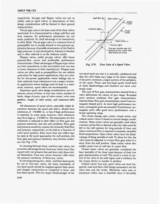
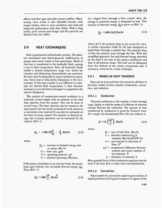
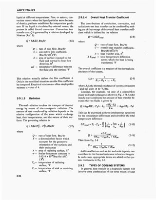
![AMCP 706-123
Fig. 2-71. Counterflow Plane Wall Heat Exchanger
transfer. If it is found that the heat dissipated from the
surfaces ofthe system is insufficient to maintain a satis-
factory fluid temperature, then a heat exchanger is re-
quired. Most heat exchangers for hydraulic fluids are
either air-cooled or water-cooled.
2-9.2.1 Air-cooled Heat Exchangers
Air is often used as the coolant in heat exchangers
for mobile hydraulic systems, or in stationary systems
which generate moderate amounts of heat. A blower or
fan is usually used to circulate the air across finned
tubes through which the hydraulic fluid flows (Fig.
2-72). Air-cooled units are limited to applications
where the desired hydraulic fluid outlet temperature is
at least 10°F above the dry bulb air temperature.
2-9.2.2 Water-cooled Heat Exchangers
The use of water as a coolant is common practice in
stationary systems. The film coefficient on the water
side is generally the same order of magnitude as on the
hydraulic-fluid side. Therefore, water-cooled heat ex-
changers are usually shell-and-tube type where the
heat-transfer area on the cold side is approximately the
same as on the hot side. Such an exchanger is shown
in Fig. 2-73. It consists of a tube bundle within a shell.
The tubes are baffled (not shown) so that the coolant
flow in the shell is perpendicular to the tube axis. Most
shell-and-tube heat exchangers used in hydraulic sys-
tems are either single- or double-pass units. In a single-
pass unit, the two liquids generally flow in opposite
directions. In a double-pass exchanger, the hydraulic
fluid generally enters the same end at which the water
enters and leaves.
RELIEF FOR HIGH VOLUME PUMP
RELIEF FOR LOW VOLUME PUMP
REDUCING VALVE
SUCTION
STRAINER "SUCTION
STRAINER
TO 4 WAY
, VALVE a
.WIPECYL.
FINNED CONDUCTORS
Fig. 2-72. Hydraulic Circuit With Air-cooled Heat Exchangers
[From: Pippenger and Hicks, Industrial Hydraulics. Used by permission of McGraw-Hill, Inc.]
2-37](https://image.slidesharecdn.com/884519-170327080602/85/Fluid-mechanics-material-67-320.jpg)
![AMCP 706-123
Oil in
Water in Oil out
■%A Y> w >>"">•>>>>>>>>">>>>>>>>>>>•>">>">"•>"">> "
•j j j > J jWrrri /^&2 ' " ' " " " " ' >>>> " ' " "'' " " "" "" " '" " **'»>»
Water out
Fig. 2-73. Shell and Tube Single-pass Heat Exchanger
[From: E. C. Fitch, Fluid Power and Control Systems.
Used by permission of McGraw-Hill, Inc.]
Water-cooled, shell-and-tube heat exchangers are
compact and low in initial cost. They can be used to
obtain lower hydraulic-fluid temperatures than the air-
cooled exchangers. Limitations include the possibility
of corrosion and the cost of a continuous water supply.
Copper alloys are used in standard heat exchangers,
and special corrosion-resistant alloys are available.
Removable tube bundles facilitate cleaning.
2-10 HYDRAULIC PIPING
The design of the liquid conductors is just as impor-
tant as the design of other components of a hydraulic
system. The hydraulic piping serves to contain and
conduct the hydraulic fluid from one part of the system
to another. Inadequate attention to piping design can
lead to poor system operating characteristics and
low efficiency.
Hydraulic piping systems are usually constructed
from three types of fluid conductors-pipe, tubing, and
flexible hose. Hose is used to accommodate relative
movement between components. Most ofthe stationary
piping, however, is either tubing or pipe. The advan-
tages of tubing include better appearance, greater flexi-
bility, better reusability, fewer fittings, and less leak-
age. The principal advantage of pipe is its relatively
low cost.
2-10.1 HYDRAULIC LINE SIZE
The sizing of liquid conductors for hydraulic piping
depends on considerations of mechanical strength,
volume flow rates, pressure drop, pressure surges, and
compression time.
2-10.1.1 Pressure Drop
The efficiency of a hydraulic line is determined by
the pressure loss which should be as small as possible.
The pressure required at the inlet is equal to the sum
of the required outlet pressure and the pressure drop in
the line. Hence, minimum pressure drop means mini-
mum pumping requirements.
One convenient method for determining pressure
drop in the distribution system-including piping,
valves, headers, etc.-is to convert all flow passages to
equivalent lengths of the same size liquid conductor.
The length of a line of one diameter can be converted
to the equivalent length of a given diameter line by the
relation (Ref. 1)
{%'■ ft (2-13)
where
Le= equivalent length of line, ft
L = length of line, ft
De = inside diameter of equivalent
line, in.
D = inside diameter of line, in.
Flow passages such as valves, tees, elbows, etc., can be
converted to equivalent lengths with (Ref. 1)
KDe
12/ ,ft (2-14)
where
K = loss coefficient
/= coefficient of friction of liquid
in the fitting
Values of the loss coefficient for several flow elements
are given in Table 2-1. For some components, such as
sequence valves, the loss coefficients change as the flow
conditions vary.
When the components of the liquid distribution sys-
tem have been converted to equivalent lengths of a
common size, the pressure drop can be estimated from
either of the two following expressions (Ref. 1)
AP = 0.01345
Mil)'psi (2-15)
where
AP = 0.0808fslf2
Q), psi (2-16)
AP = pressure drop, psi
L = line length, ft
D = inside line diameter, in.
U = liquid velocity, fps
2-38](https://image.slidesharecdn.com/884519-170327080602/85/Fluid-mechanics-material-68-320.jpg)
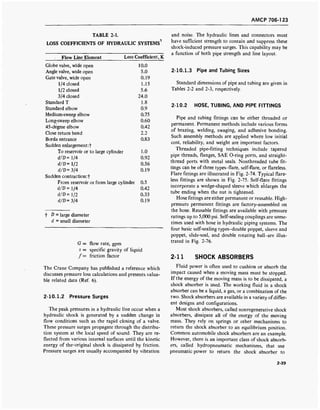
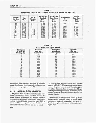
![AMCP 706-123
Two-Piece Type
Three-Piece Type
Inverted-Flare Type
Fig. 2-74. Typical Flare Fittings for Hydraulic Tubing
[From: Fluid Power Issue; Machine Design. Used by
permission of Penton Publishing Co.]
2-11.2 HYDROPNEUMATIC SHOCK
ABSORBERS
A hydropneumatic shock absorber works on essen-
tially the same principle as the hydraulic shock ab-
sorber except that both a liquid and a gas are used as
the working fluids. A simplified sketch of a hydro-
pneumatic mechanism is shown in Fig. 2-78. As the mass
to be stopped drives the piston inward, liquid metering
through the orifices and compression of the gas brings
the mass to a stop. The compressed gas then expands
and returns the piston to the starting position. There
are numerous variations of the hydropneumatic shock
absorber. Many designs have a separate cylinder or
container for the gas. Hydropneumatic configurations
similar to that shown in Fig. 2-78 are frequently used
in aircraft landing gear struts and are referred to as oleo
shock absorbers or oleo struts. Artillery recoil mech-
anisms, an important application of hydropneumatic
shock absorbers, frequently use separate cylinders for
the gas and the liquid. Several methods of driving the
piston into the gas cylinder are used. Fig. 2-79 shows
a simplified sketch of a recoil mechanism with separate
pistons for each cylinder being driven by the same mov-
ing mass.
Regulor Ferrule
Inverted Ferrule
££SS£§§
«SSSS^s^ >.'.'.'/':i'*"""
Threaded Sleeve
iiyiji in> in 11
vi 111111-rrr*
Double Compression
Fig. 2-75. Typical Flareless Fittings for Hydraulic
Tubing
[From: Fluid Power Issue; Machine Design. Used by
permission of Penton Publishing Co.]
2-41](https://image.slidesharecdn.com/884519-170327080602/85/Fluid-mechanics-material-71-320.jpg)
![AMCP 706-123
CZr^u S$E?
Connected Disconnected
(A) Double Poppet
U
4
Connected
n Disconnected
(B) Sleeve and Poppet
Connected
(C) Slide-seal
Disconnected
j ^y
Connected
(D) Double Rotating Ball
Fig. 2-76. Typical Self-sealing Couplings for Hydraulic Hose
[From: Fluid Power Issue; Machine Design. Used by permission of Penton Publishing Co.]
2-42](https://image.slidesharecdn.com/884519-170327080602/85/Fluid-mechanics-material-72-320.jpg)
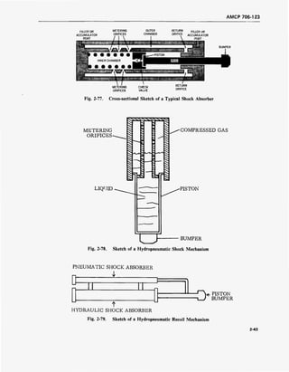
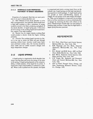
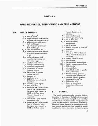
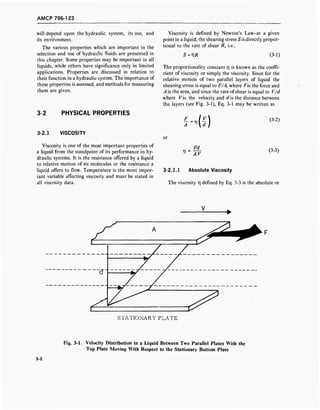
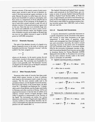
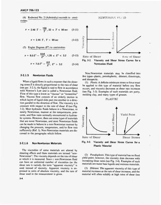
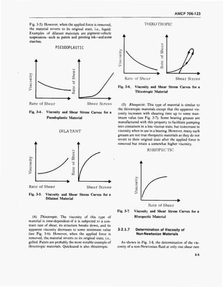
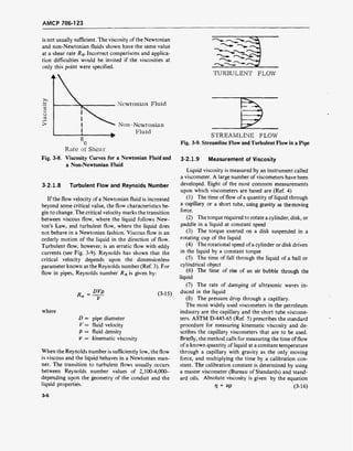
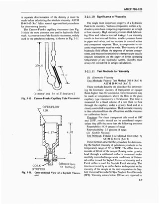
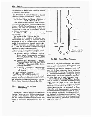
![AMCP 706-123
TABLE 3-1.
VISCOSITY REQUIREMENTS OF FIVE SPECIFICATION HYDRAULIC FLUIDS*
Temperature,
°F
MIL-H-5606B MIL-H-8446B MIL-H-13866B (MR) W-B-680a MIL-H-27601A
-65 3000 (max) 2500 (max) To be reported
-40 500 (max) 1800(max) 4000 (max)
-30 4200(max)
100 To be reported 55 (min) 3.5 (min)
at 122°F
385 (max)
at0°F
130 10.0 (min)
210 To be reported 15 (min) 1.3 (min)
at 212°F
3.2 (min)
400 2.5 (min) Report at
500°F
n centistokes.*AU viscosities l
References: MIL-H-5606B; Hydraulic Fluid, Petroleum Base, Aircraft, Missile, and Ordnance.
MIL-H-8446B; Hydraulic Fluids, Nonpetroleum Base, Aircraft.
MIL-H-13866B; Hydraulic Fluid, Petroleum Base, Artillery Recoil, Special
W-V-680a;Brake Fluid, Automotive.
MlL-H-2760A; Hydraulic Fluid, Petroleum, High Temperature, Flight Vehicle.
3-2.2.1 ASTM Viscosity-temperature Charts
Many systems have been developed for expressing
the viscosity-temperature characteristics of liquids.
The most widely used procedure utilizes the viscosity-
temperature charts published by ASTM (see Fig. 3-13).
These charts, available from ASTM, are described in an
ASTM Method (Ref. 13) and in a Federal Test Method
(Ref. 14). Five different viscosity-temperature charts
similar to that shown in Fig. 3-13 are available with
various temperature ranges and either kinematic or
Saybolt Universal viscosity scales. These charts are
constructed so that the plot of viscosity vs temperature
is a straight line for most petroleum liquids. Thus, only
two viscosity measurements, usually at 100° and
210°F, need to be made to determine a line from which
the approximate viscosity at any other temperature can
be read.
The viscosity-temperature charts are useful for pre-
dicting viscosity only when the graph for a liquid is
linear. In most instances this will occur over the tem-
perature range that a given liquid is Newtonian. How-
ever, many Newtonian petroleum liquids will deviate
from linearity at low viscosities, i.e., high temperature.
Many liquids deviate from linearity near their cloud
points (par. 3-2.6.2) because of the formation of wax
particles. For non-Newtonian liquids, and for New-
tonian liquids that are in nonlinear conditions ofbehav-
ior, the plot of viscosity vs temperature cannot be used
to predict viscosity. The actual viscosity-temperature
properties of the liquid must be determined and plotted.
The ASTM charts are based on a modified
Walther equation:
log [log(i> + c)] = A log°R + B (3-17)
where
c = a constant
° R = temperature, °Rankine
V = viscosity, cSt
A,B = constants for each fluid
The ASTM chart expresses c as a constant varying
from 0.75 at 0.4 cSt to 0.6 at 1.5 cSt and above (Ref.
15). The use of this equation in chart form obviates the
necessity of determining the constants A and B when
two or more viscosities are determined experimentally
and plotted.
3-2.2.2 ASTM Slope
A simple method of expressing a change in viscosity
with temperature is by using the slope of the curve on
the ASTM charts. Since the curve accurately portrays
the viscosity-temperature characteristics of a particular
liquid, its slope is a measure of the liquid's sensitivity
to a change in temperature. The slope may be deter-
mined graphically from the chart as the tangent of the
angle formed by the viscosity-temperature line and the
3-9](https://image.slidesharecdn.com/884519-170327080602/85/Fluid-mechanics-material-83-320.jpg)
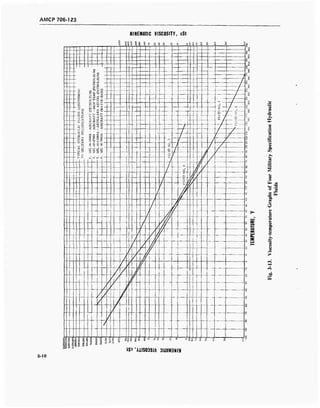
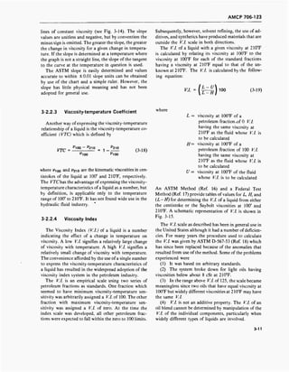
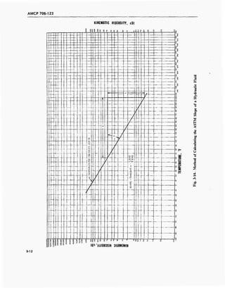
![AMCP 706-123
c) L
— Lt_
_ o i_ o
_1 ™~ I—1 z<c «<_> — • •7
oo
Z^.pD U
• — I • i
1—1
~
>
1111 H
100 1 '
U
H £CO
O
U
CO
i—i
1 ^ „ >
700 V. i.
100°F 210°F
Fig. 3-15. Schematic Representation of Viscosity Index (V.l.)
[From: Lubrication, Vol. 47 (1961). Used by permission of Texaco, Inc.]
In spite of its shortcomings, the V.l. remains the
most popular system for expressing viscosity-tempera-
ture characteristics of fluids. Numerous suggestions
have been proposed to eliminate the shortcomings of
the system or to find a more fundamental means of
expressing viscosity-temperature characteristics. Most
of the suggested systems were too complex for general
use or had faults of their own, so a method (Refs. 16,
17) was developed to correct the deficiencies in the
ASTM K/.'s above 100 without shifting the values
between 0 and 100. Values above 100 are designated
Viscosity Index Extended ( V.I.E) (Ref. 19) to dis-
tinguish them from values obtained by the previ-
ous method.
3-2.2.5 Test Methods for Viscosity-temperature
Properties
(1) Viscosity-temperature Charts
Test Methods: ASTM D-341-43 (Ref. 13)
FederalTestMethod9121.1(Ref. 14)
t> These methods provide specifications for standard
viscosity-temperature charts (e.g., Fig. 3-13) for pe-
troleum fluids for both kinematic and Saybolt viscosi-
ties and for a range of temperatures. Charts available
from ASTM Headquarters are:
(a) Chart A. Saybolt Universal Viscosity:-30° to
+ 450°F, 33 to 100,000,000 Saybolt Universal
Seconds
(b) Chart B. Saybolt Universal Viscosity,
Abridged:-30° to + 350°F, 33 to 100,000 Say-
bolt Universal Seconds
(c) Chart C. Kinematic Viscosity, High Range:
-30° to +450°F, 2 to 20,000,000 centistokes
(d) Chart D. Kinematic Viscosity, Low Range:
-30° to +450°F, 0.40 to 100 centistokes
(e) Chart E. Kinematic Viscosity, Low Tempera-
ture Range:-100° to +450°F, 2.0 to 20,000,000
centistokes
(f) Chart F. Kinematic Viscosity, Extended
Range:-100° to +700°F, 0.40 to 20,000,000
centistokes
(2) Calculation of Viscosity Index
Test Methods: Federal Test Method 9111.2 (Ref. 17)
ASTM D-2270-64 (Ref. 16)
These methods provide tables and equations for cal-
culating the V.l. of petroleum products from their vis-
cosities at 100° and 210°F. Tables are provided for liq-
uids with viscosities at 210°F between the values of 210
and 75.0 cSt.
Tedious calculation of V.l. can be eliminated by the
use of data in ASTM Data Series 39a, ASTM Viscosity
Index Tables Calculatedfrom Kinematic Viscosity, Sep-
tember 1965. This reference gives V.l. in the following
3-13](https://image.slidesharecdn.com/884519-170327080602/85/Fluid-mechanics-material-87-320.jpg)
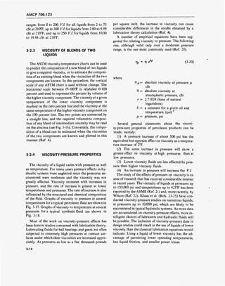
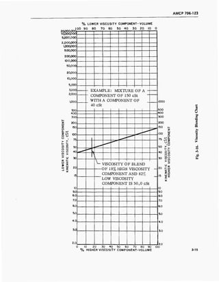
![AMCP 706-123
W
wi—i
O
CM
I—i
h
2
Kl
U
i—i
O
U
l—i
>
IOO°F/ 210OF„^
32°F /
425°F
• i i i i i i i i ! i i i i .
1,000,000
100,000
10,000
1,000
100
10
1
0.1
0 50 100 150
PRESSURE, PSIG x 10'3
Fig. 3-17. Viscosity vs Pressure at Several Temperatures
for a Typical Petroleum Fluid
21
[From: ASME Pressure-Viscosity Report, Vol. 2 . Used
by permission of ASME]
3-2.5 VISCOSITY-SHEAR CHARACTERISTICS
Some aircraft and many industrial hydraulic fluids
currently in use contain polymeric thickeners called
Viscosity Index improvers, or " V.l. improvers", to
reduce viscosity change due to temperature. When liq-
uids containing these V.l. improvers are subjected to
high rates of shear, they often suffer a loss in viscosity
and VI. because of degradation of the polymers. The
unit of shear rate is the reciprocal second (sec" ). A
shear rate of one reciprocal second occurs when paral-
lel planes 1 cm apart move in opposite directions at a
relative speed of 1 cm/sec. High shear rates will occur
where speeds are high and clearances small. Some typi-
cal shear rates are shown in Table 3-2 (Ref. 26). Circu-
lation ofa hydraulic fluid through a system subjects the
fluid to rapid shear rates and sudden pressure changes
as it passes through orifices and close tolerance areas
(Ref. 27). The resultant loss in viscosity may be either
a permanent loss, or a temporary loss, or a combination
of the two.
3-2.5.1 Temporary Viscosity Loss Due to
Shear
Temporary viscosity loss is due to orientation or
"lining-up" of the long chain polymer molecules in the
direction of flow. The polymer molecules thicken a
liquid more when they are oriented in a random man-
ner, than when they are oriented in the direction of
flow. The orientation of the molecules can actually be
seen when the flow in transparent tubes is observed
under polarized light (Ref. 28). When the shear-
ing stress is removed, the liquids regain their origi-
nal viscosity.
Temporary loss of viscosity has two important ef-
fects on the performance of hydraulic fluids-an in-
crease in leakage and a reduction offluid friction. Leak-
age around close fitting parts increases as the viscosity
decreases and can result in reduced system efficiency if
the rate becomes too great. However, the reduction in
fluid friction that accompanies reduced viscosity in-
creases system efficiency and performance. Several
methods for measuring the temporary viscosity de-
crease have been developed. One method uses a bank
of capillary tubes; another uses a rotating tapered plug
viscometer. The concentric cylinder is another com-
mon apparatus. Any one of these methods is sufficient
for determining the relationship between viscosity and
shear rate (Ref. 28).
TABLE 3-2.
ESTIMATED SHEAR RATES OF LUBRICANTS
Application
Radial Clearance
Between Moving
and Stationary
Parts, in.
Relative
Velocity
of Parts
Shear Rate,
sec"1
Piston-cylinder clearance in automotive engine
Plain journal bearing (2-in. diameter)
Ball-type hydraulic pump
Bosch piston-type Diesel fuel pump
0.001
0.001 to
0.0001
0.0003
0.00004
200-400
in./sec
1800 rpm
3500 rpm
36 in./sec
200,000 to
400,000
188,000 to
1,820,000
3,000,000
900,000
[From: Klaus and Fenske, "Some Viscosity shear Characteristics of Lubricants", Lubrication Engineering26
.
Used by permission of ASLE.]
3-16](https://image.slidesharecdn.com/884519-170327080602/85/Fluid-mechanics-material-90-320.jpg)
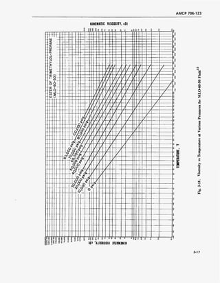
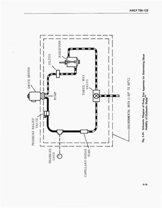
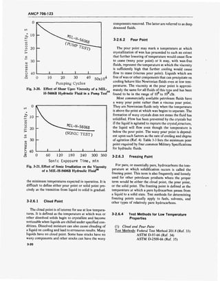
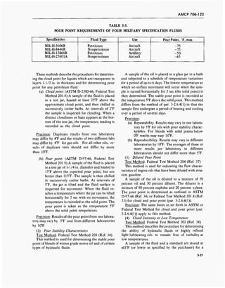
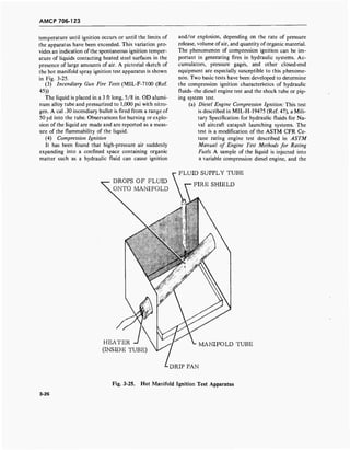
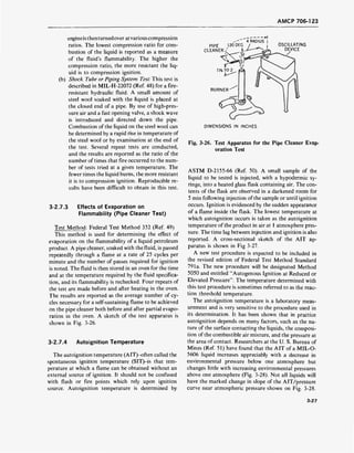
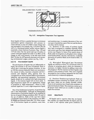
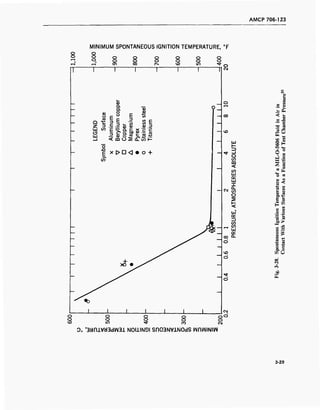
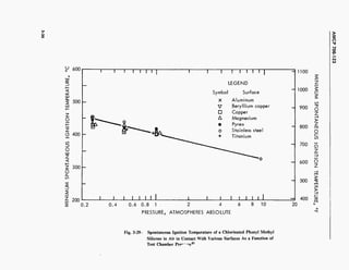
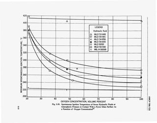
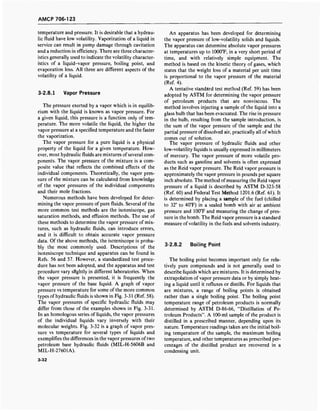
![AMCP 706-123
1000
bo
X
£
£
w
D
to
W
Pi
O
$
0.01
0.001
120 150 20u 280
TEMPERATURE, °F
Fig. 3-31. Vapor Pressure vs Temperature of Typical Fluids (Approximate)
[From: F. D. Yeaple, Hydraulic and Pneumatic Power and Control58
.Used by permission of McGraw-Hill, Inc.]
Boiling of a hydraulic fluid in a system can result in
failure or component damage. Formation of vapor in
control lines, actuators, servomotors, and other compo-
nents will adversely affect the operation of those com-
ponents. Boiling on the suction side of the pump will
reduce the pump delivery and cause cavitation in
the pump.
3-2.8.3 Evaporation
Evaporation loss is widely used in the United States
to describe the volatility of liquid products such as
hydraulic fluids, lubricants, and greases. The actual
evaporation rate is not an overly important factor in
closed-loop hydraulic systems which are not exposed to
the atmosphere, but can be important in systems with
reservoirs vented to the atmosphere. Several tests for
determining evaporation loss have been developed and
adopted as ASTM or Federal Test Methods. Most of
these tests are essentially the same in that they consist
of heating a sample of the liquid in the presence of air
and observing the results. They differ in their proce-
dure, apparatus, and method of reporting results.
3-33](https://image.slidesharecdn.com/884519-170327080602/85/Fluid-mechanics-material-107-320.jpg)
![AMCP 706-12?
X
w
cd
D
w
cd
OH
cd
O
CL,
iuuu
100
10
o.i
o.oi
...
-4- -r-i-M-
-T- T '•■+T- 1-4 1' j
-r-r- -1 ff!
"I" TT" ' /'
" !'-■"
--}•■ -
i—
w'-'-- —1--
i vr
ft 1 1
-^ -
i !
i! p-1
' VT
—1—1 -——/——
^1
^ 1 :
i
T'lTT
1 i 1
, i 1
j
! i1 1
-tfrt~4yjn~ *&■*-*¥■
4- 1—_
• ■ ■ T
rV'^ - ... -r__
oQ
>-1- ifft- i i 1 ii
i I 1
1
! I w
i ; ! !
!
■ 1--
1 ' 1 !
!
" 1j
iTI */f i ! i j ; 1 i
i i» i
; r : r T^ :
j;| | !
wrrt-P^i^y: f4-1 i -—1 //!r
^ 1 ITT" ! ' j !
! T it"::;.].:!'.] a 1
1 j n ! M
-—
! ; LL Ml -ff-W -! 14-y!
i M I
ii :its)Jr
M/r
ny v y/ T T ' 1 .
4< > vv
jf-i/n.:.-.!-',<*> y I"-L„.
ztttb1- rv
<C u
- O^ 0>v
+> ff/ H-j-j-h
....j or ^- in^
SvyTT /
._..JJ^LLL._V1_ IJY L i
I i
! 1 •$/ / i !
—t—
J
<> /44-L; jL 4_L.. .' *_ i_ .1
' 1/ *T
" 1 i
^/ ■-+-, y1 ! J ;
' y J*
',<?
' * t
^ 1
■V I
1/ i
/ 1
r 1
1
200 300 400
TEMPERATURE, °F
500
Fig. 3-32. Vapor Pressure vs Temperature of Several Types of Hydraulic Fluids
(1) Evaporation (Tackiness Test):
Test Method: Federal Test Method 353 (Ref. 62)
This test method is intended for hydraulic fluids
which contain viscosity improvers (such as acryloid
polymers). It serves as a means of determining the
tackiness of the viscosity improver after the base liquid
has been evaporated.
A glass slide is dipped in a sample of the fluid at
room temperature and then suspended in an oven. The
oven is heated to the temperature for the period of time
called for in the fluid specification. The condition ofthe
fluid on the slide is reported. A fluid is considered to
have passed the test if it is still oily and not hardior
tacky.
(2) Evaporation Loss:
Test Methods: Federal Test Method 351.2 (Ref. 63)
ASTM D-972-56 (Ref. 64)
3-34](https://image.slidesharecdn.com/884519-170327080602/85/Fluid-mechanics-material-108-320.jpg)
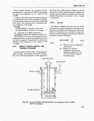
![AMCP 706-123
Density is of great importance when calculating flow
of hydraulic fluids through components such as valves,
pumps, and motors. The density enters into the flow-
energy equations and changes in density will affect the
results obtained from the equations. High-density liq-
uids may generally be eliminated from consideration
because of weight limitations imposed on the hydraulic
system, especially in airborne systems.
Density is a function of both temperature and pres-
sure. An increase in temperature produces a decrease
in density. Changes in density due to expansion of
fluids between the minimum and maximum system
temperature can cause serious malfunctions unless con-
sidered in the design of a system. For a high-tempera-
ture aircraft or missile hydraulic system operating be-
tween the extreme temperatures of-65° and 500°F, the
fluid volume can be expected to change up to 35 per-
cent (Ref. 66). Graphs of density vs temperature for
several types of fluids are shown in Figs. 3-34 and 3-35.
Density also varies with pressure. An increase in
pressure produces an increase in density. However, the
normal pressures encountered in most hydraulic sys-
tems are not high enough to produce significant
changes in density. A graph of relative density vs pres-
sure for a typical MIL-H-5606B hydraulic fluid is
shown in Fig. 3-36 (Ref. 67). Pressures as high as 5000
psi (which is higher than the pressures normally en-
countered in hydraulic systems) produce changes of
less than 2.5 percent in the density of the MIL-H-
5606B fluid. As the pressures are increased to very high
levels, large and significant changes in density are pro-
duced. The ASME Pressure-Viscosity Report (Ref. 21)
gives density data on several liquids at pressures up to
150,000 psi. Wilson (Ref. 22) reports density-pressure
data (see Fig. 3-37) on MLO-60-50 fluid (an ester of
trimethylolpropane, the base fluid of MIL-L-9236 oil).
Both of these reports indicate that changes in density
up to 35 percent are produced at these higher pressures.
u
b0
1.5
1.4
1.3
1.2
> 1.1
i->i—i
Z
a i.o
0.9
0.7
T
^VRINATED
J££22^*BON
j^^TE ESTFER
WATER-GLYCOL
JXLICONE
" 8MULSIO?
180 200100 120 140 loO
TEMPERATURE, °F
Fig. 3-34. Density vs Temperature of Typical Fluids (Approximate)
[From: F. D. Yeaple, Hydraulic and Pneumatic Power and Contro^.Used by permission of McGraw-Hill, Inc.]
3-36](https://image.slidesharecdn.com/884519-170327080602/85/Fluid-mechanics-material-110-320.jpg)
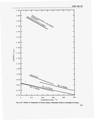
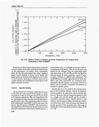
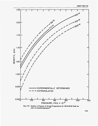
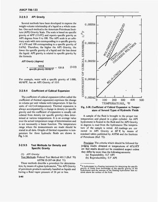
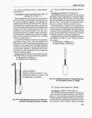
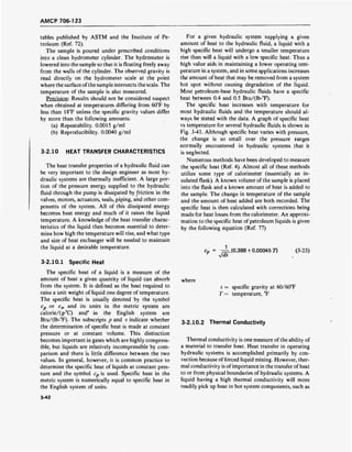
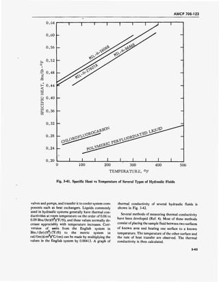
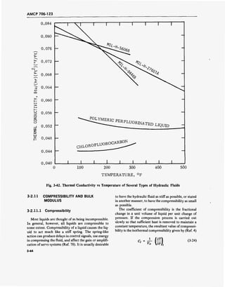
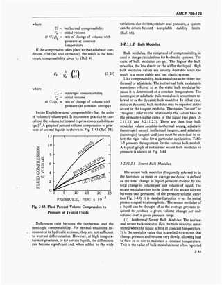
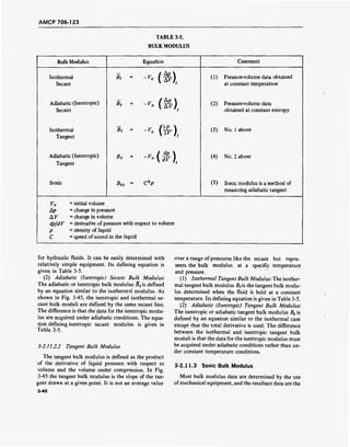
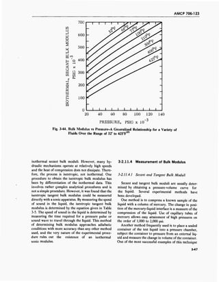
![AMCP 706-123
side of the container. From the knowledge of path
lengths and signal frequencies, the speed can
be calculated.
The ultrasonic bulk modulus methods have some
advantages over the pressure-volume methods. They
allow rapid measurement ofbulk modulus and they are
frequently more accurate because the measured quanti-
ties themselves, rather than their derivatives, are used
in calculation of bulk modulus. The sonic methods
have a disadvantage in that rather complex equipment
is required to measure density and sonic speed in a
liquid under pressure. A schematic drawing of a typical
apparatus for measurement of bulk moduli by sonic
speed is shown in Fig. 3-46 (Ref. 66).
3-2.11.4.3 Estimation of Bulk Modulus (Penn State
Method)
Researchers at the Petroleum Refining Laboratory
of Pennsylvania State University have developed a
procedure for the measurement and prediction of bulk
modulus for fluids (Ref. 23). By studying the pressure-
volume-temperature properties of a large number of
liquids they developed a series of empirical equations
for determining liquid bulk modulus at any tempera-
ture or pressure once the bulk modulus is known (with
high accuracy) at any one condition oftemperature and
pressure. They have determined that the effect of pres-
sure on the bulk modulus is essentially independent of
the liquid molecular structure and the temperature.
Use of their procedure for pressures in the range of 1
to 10,000 psi and temperatures of 0° to 218°C (32° to
425°F) will yield bulk modulus data with an accuracy
of ± 5 percent. A brief outline of their method is given.
(1) Bulk Modulus-pressure Equation:
Bt = B0 + 5.30p (3-26)
where
Bt = isothermal secant bulk modulus
at gage pressure p and
temperature t, °F
Bo = isothermal secant bulk modulus
at 0 psig and temperature t, °F
p = pressure, psig
(2) Bulk Modulus-temperature Equation:
[log(fifl /Bt2)=ß(t2-t
4 (3-27)
where
V
V
isothermal secant bulk modulus
at gage pressure p and
temperature tv °F
isothermal secant bulk modulus
at gage pressure p and
temperature t2, °F
Oscilloscope
Signal
trigger
delay ,500 K£_
Sine wave
pulser
Amplifier
Pressure-temperoture
cell
3^?-Heaters
500 KC quartz
transducer
(generator)
Fluid
sample
500 Hi quartz
transducer
(receiver)
Fig. 3-46. Apparatus for Measurement of Adiabatic Bulk Modulus by Sonic Speed
[From: E. Lewis and H. Stern, Design of Hydraulic Control Systems66
. Used by permission of McGraw-Hill, Inc.]
3-49](https://image.slidesharecdn.com/884519-170327080602/85/Fluid-mechanics-material-123-320.jpg)
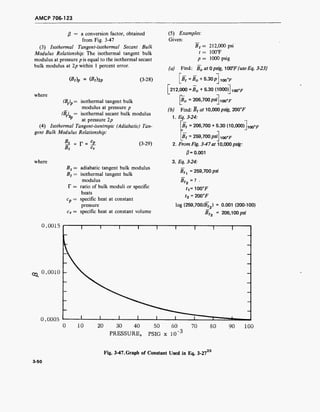
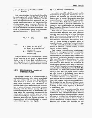
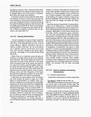
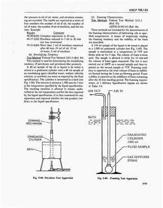
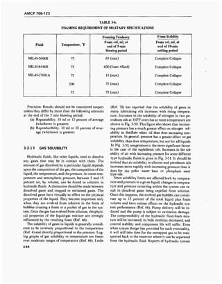
![AMCP 706-123
z
o1—1
Hi—<
Q
Z
>* o -J
1—1
u o
J • i—i
i—i
D
Q
H
rn
a
-1
O
1/3
<<
z i—1
w sÜ
o
BJ
H1—1
Z
0.50 -
0.40 -
0.30 -
0.20 -
0.10 -
DISTILLATE WHITE OIL
NAPHTHENIC OIL
10 20 30
PRESSURE, PSIA
Fig. 3-50. Nitrogen Solubility vs Pressure of Two Petroleum Products
[From: R. L. Leslie, The Relation of Fluid Properties and High Temperature
Hydraulic Performance1
*. Used by permission of ASLE]
S
D
O
>
E-►—i
m
ID
O
w
0 0.4 0.8 1.2
PRESSURE, ATMOSPHERES
Fig. 3-51. Air Solubility vs Pressure of Typical Fluids
[From: F. D. Yeaple, Hydraulic and Pneumatic Power
and Control5
*. Used by permission of McGraw-
Hill, Inc.]
malfunctions have frequently been traced to air separa-
tion problems. Dead-ended or single line systems simi-
lar to simple hydraulic brake systems are particularly
prone to air evolution and entrapment (Ref. 66). A
small amount of liquid circulation built into such sys-
tems can help to relieve the problem.
3-2.14 LOW-TEMPERATURE STABILITY
3-2.14.1 General
Hydraulic fluids are often stored for prolonged peri-
ods oftime at low temperature. During this storage, the
liquid should not undergo any permanent changes in its
properties or show evidence of gelling, crystallization,
or separation of any of its components. Gelling is the
formation of jelly-like materials due to coagulation of
a component or components of the liquid. Crystalliza-
tion is the formation of crystals or crystalline material
by a component or components of the liquid. Separa-
tion is the removal from suspension or solution of com-
ponents or additives in the liquid. Many specification
liquids, however, will be deemed to have satisfactory
low-temperature stability if any separated components
will readily return into solution at the lowest an-
ticipated operating temperature.
Low-temperature properties of hydraulic fluids
become important in storing fluids in cold environ-
ments or when hydraulic systems are subject to periods
3-55](https://image.slidesharecdn.com/884519-170327080602/85/Fluid-mechanics-material-129-320.jpg)
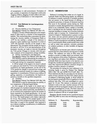
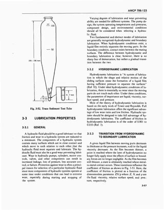
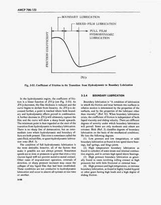
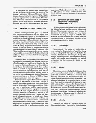
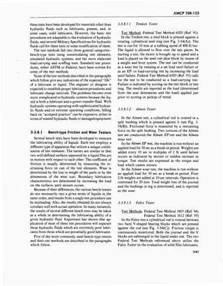
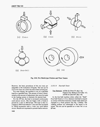
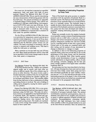
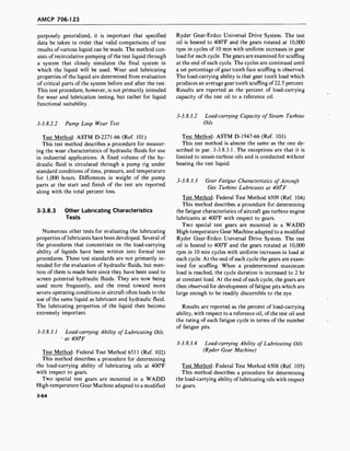
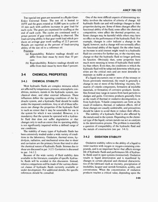
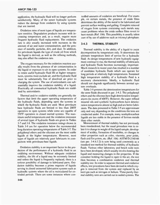
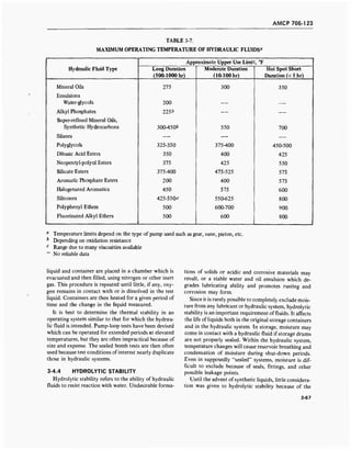
![AMCP 706-123
TABLE 3-8.
OXIDATION AND VARNISHING RESISTANCE OF HYDRAULIC FLUIDS
Hydraulic Fluid Type
Resistance to
Oxidation
Tendency to Form
Solids or Varnish
Mineral Oils Good
Water-in-mineral Oil Emulsions Good —
Water-glycols Good —
Alkyl Phosphates Good —
Super Refined Mineral Oils, Synthetic
Hydrocarbons, and Silanes Fair to good Large
Polyglycols Fair Small to medium
Dibasic Acid Esters Good Large
Neopentyl-polyol Esters Good Large
Silicate Esters Fair to good Small to medium
Aromatic Phosphate Esters Good Medium
Halogenated Aromatics Excellent to 500°F Small
Silicones Excellent to 400°F
Good above 400°F
Small
Small
Polyphenyl Ethers Excellent to 500°F Small
No reliable data
[From: F. D.Yeaple, Hydraulic and Pneumatic Power and Control58
. Used by permission of McGraw-Hill, Inc.]
outstanding hydrolytic stability of petroleum oils.
However, stability of synthetic fluids and of some addi-
tives in hydraulic fluid formulations must be consid-
ered. Table 3-10 presents data on the relative hy-
drolytic stability of several classes of hydraulic fluids.
The most moisture-sensitive of these hydraulic fluids
are the silicate esters. Hydrolysis of these fluids pro-
duces a silicate sludge which readily clogs filters, servo
valves, and capillary passages. Great care is needed to
insure that no water is present in the system prior to
charging with this type of fluid.
3-4.5 RADIATION RESISTANCE
It has only been since the early 1950's that the radia-
tion resistance of hydraulic fluids has become impor-
tant. In the design of modern weapon systems, aircraft,
and mechanical devices, hydraulic systems are fre-
quently expected to be exposed to nuclear radiation. Of
all system components, the hydraulic fluid is the most
susceptible to damage by radiation. Since convention-
ally used hydraulic fluids and lubricants are especially
susceptible, the effects of radiation on their perform-
ance should be considered in the design of almost all
systems. However, there is no general requirement for
radiation resistance in most hydraulic fluid specifica-
tions.
Considerable basic work has been done on the radia-
tion of simple organic structures. With the more com-
plicated molecular structures characteristic of lubri-
cants, both petroleum and synthetic, it has not been
feasible to make studies of the precise reactions that
occur. The empirical observations are: (Ref. 107) (a)
viscosity may at first be decreased, but eventually in-
creases, (b) acidity increases, (c) volatility increases, (d)
foaming tendencies increase, (e) coking tendencies gen-
erally increase but occasionally decrease, (f) flash
points decrease, (g) autogeneous ignition temperatures
decrease, and (h) oxidation stability decreases.
In addition to the listed changes in physical and
chemical properties, gas is always liberated (Ref. 107).
3-68](https://image.slidesharecdn.com/884519-170327080602/85/Fluid-mechanics-material-142-320.jpg)
![AMCP 706-123
TABLE 3-9.
DETERIORATION TEMPERATURE OF
HYDRAULIC FLUIDS
TABLE 3-10.
HYDROLYTIC STABILITY OF
HYDRAULIC FLUIDS
Hydraulic Fluid Type
Incipient Thermal
Degradation
Temperature °F
Super-refined Mineral Oils,
Synthetic Hydrocarbons,
and Silanes 600-700
Polyglycols 500-550
Dibasic Acid Esters 525
Neopentyl-polyol Esters 575
Silicate Esters 550-600
Aromatic Phosphate Esters 500-600
Halogenated Aromatics 600-650
Silicones 625-800
Polyphenyl Ethers 750-850
[From: F. D. Yeaple, Hydraulic and Pneumatic Power
and Control . Used by permission of McGraw-Hill,
Inc.]
For petroleum liquids the gases are frequently hydro-
gen and methane. The remaining products ofdecompo-
sition are frequently gels that tend to clog hydraulic
systems. The formation of the gases and gels presents
a difficult design problem, and provisions must be
made in the system for their presence.
Although some changes in lubricants have been
found after radiation doses of 107
roentgens,2
the major
effects are observed between 108
and 109
roentgens
(Refs. 107, 108). Beyond 10 roentgens most liquid lu-
bricants have been damaged to the extent that they are
completely unserviceable.
In general, petroleum lubricants are more resistant
to radiation damage than other lubricants. An excep-
tion is the polyphenyl ether family which is very resist-
ant to damage. Currently, the silicone liquids exhibit
the poorest radiation resistance of all the high tempera-
ture liquids (Ref. 4). Inclusion of atoms other than
carbon, hydrogen, and oxygen in the molecule gener-
ally reduces radiation resistance. Table 3-11 presents
data on the relative radiation resistance of various hy-
draulic fluids.
2
1 roentgen = absorption of 93 ergs/g water or 83 ergs/g air.
1rad = 100 ergs/g.
Hydraulic Fluid Type
Comparative
Rating
Super-refined Mineral Oils,
Synthetic Hydrocarbons, and
Silanes Excellent
Polyglycols Good
Dibasic Acid Esters Fair
Neopentyl-polyol Esters Fair
Silicate Esters Poor to Fair
Aromatic Phosphate Esters Fair to Good
Halogenated Aromatics Excellent
Silicones Excellent
Polyphenyl Ethers Excellent
[From: F. D. Yeaple, Hydraulic and Pneumatic Power
and Control55
. Used by permission of McGraw-Hill,
Inc.]
Considerable work has been done on the repression
of radiation damage to organic liquids by additives.
The presence of additives such as antioxidants and
foam inhibitors may offer a slight repression of the
effects of radiation.
3-4.6 CHEMICAL STABILITY TESTS
A large number of tests to determine the chemical
stability of hydraulic fluids have been proposed and
developed. Their number and variety are almost over-
whelming. Some tests are comprehensive in that they
evaluate the overall stability of the liquid over a wide
range of conditions. Others are very narrow in their
scope in that they evaluate the stability of one property
of the liquid over a more limited range of conditions.
All of the tests, however, are of two basic modes of
operation: (1) tests which measure changes in selected
properties of the liquid before and after exposure to
controlled conditions, and (2) tests which measure the
effects of the liquid on a controlled system component
or test specimen. Examples of the latter type are pump-
loop tests which measure the effect of liquids on the
pump, and oxidation-corrosion tests which measure the
changes in metals exposed to the liquids.
3-69](https://image.slidesharecdn.com/884519-170327080602/85/Fluid-mechanics-material-143-320.jpg)
![AMCP 706-123
TABLE 3-11.
RADIATION RESISTANCE
OF HYDRAULIC FLUIDS
Fluid Type
Relative
Radiation
Resistance
Mineral Oüs: MIL-H-5606 Poor
MIL-L-25598 Low
Super-refined Mineral Oils:
Naphthenic and Paraffmic Poor
Synthetic Hydrocarbons (Average) Poor
Diesters: MIL-L-7808C Poor
Triesters: MIL-L-9236B Poor
Silicate Esters Poor
Disiloxane-diesters: MLO-8515 Poor
Disiloxane: MLO-8200 Poor
Polysiloxanes Poor
Chlorinated Silicones Poor
Silicone Ester Blends: MLO-5998 Poor
Phosphate Esters Poor
Polyphenyl Ethers Excellent
[From: C. Spar, Hydraulic Fluids and Their Applica-
tions^60
. Used by permission of ASME.]
Since there is a wide variety of tests, only a few of the
more widely accepted procedures will be discussed
here. These tests can be divided into five areas of ap-
plication: general indicators of liquid stability, oxida-
tion stability tests, thermal stability tests, hydrolytic
stability tests, and radiation resistance tests. The inclu-
sion of a test in one particular category does not mean
it is limited entirely to that category-only that its
predominant use is in that general area.
3-4.6.1 Indicators of Liquid Stability
A large number ofthe tests for liquid stability consist
of determining the values of various properties of the
liquid, subjecting the liquid to controlled test condi-
tions, and then measuring the changes in the selected
properties. Those properties most often used as indica-
tors of changes in liquid stability are: color, viscosity,
flash and fire points, neutralization number, carbon
residue, precipitation number, and ash content. The
viscosity and the neutralization number are the most
commonly used indicators. Viscosity test methods have
been described in par. 3-2.1.11. Flash and fire points
have been discussed in par. 3-2.7.1.1. Details of the test
methods for precipitation number and ash content can
be found in the ASTM Test Methods (Refs. 109, 110).
3-4.6.1.1 Color
Test Methods: Federal Test Method 102.6 (Ref. 111)
ASTM D-1500-64 (Ref. 112)
This method describes a procedure for the visual
determination of the color of a wide variety of pe-
troleum products such as lubricating oils, heating oils,
diesel fuel oils, and petroleum waxes. While the color
of a hydraulic fluid may have no correlation with its
functional ability, a change in color generally does indi-
cate a change in the fluid and can be used as an indica-
tor of possible stability changes.
A measured sample of the test fluid (diluted with
kerosene when samples are darker than ASTM Color
No. 8) is placed in a standard glass sample jar in a
colorimeter, and its color is compared to the color of
standard glass panels. The color of the sample is re-
ported as the numberof the next darkest glass standard.
Precision: The data which follow should be used for
judging the acceptability of results. Results should not
be considered suspect unless they differ by more than
the following amounts:
(a) Repeatability. 0.5 color unit
(b) Reproducibility. 0.5 color unit
3-4.6.1.2 Neutralization Number
Test Methods: ASTM D-664-58 (Ref. 113)
ASTM D-974-64 (Ref. 114)
Changes in acidity or alkalinity are often used as
measures of the deterioration of liquids, particularly in
stability tests for oxidation and corrosion. Oxidation of
most organic materials can result in the formation of
acidic compounds.
The term "neutralization number" is often used in
expressing an acidity or alkalinity of lubricating liquids
and hydraulic fluids. It is defined as the number of
milligrams of potassium hydroxide required to neutral-
ize all the acids present in one gram of the sample, or
the equivalent (in milligrams of potassium hydroxide)
number of milligrams of hydrochloric acid required to
neutralize all of the bases present in one gram of the
sample. The neutralization number is a general term
that can refer to the results of different tests so the
test method and the pH of the final solution must
be specified.
3-70](https://image.slidesharecdn.com/884519-170327080602/85/Fluid-mechanics-material-144-320.jpg)
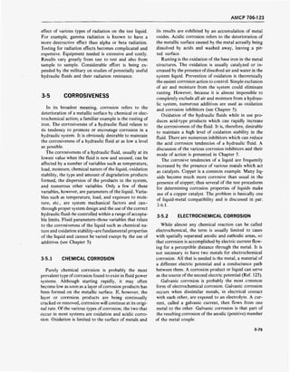
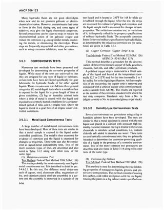
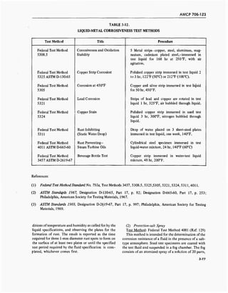
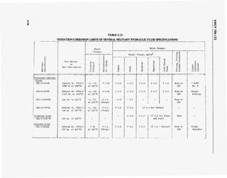
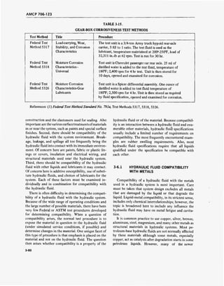
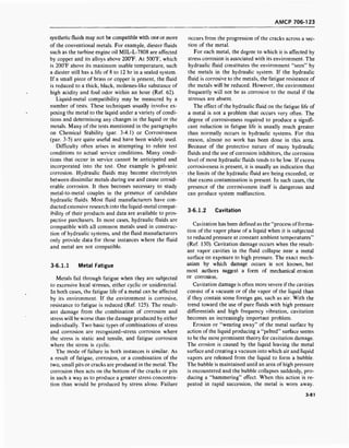
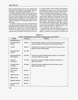
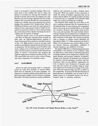
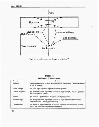
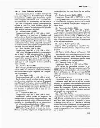
![AMCP 706-123
TABLE 3-19.
COMPARATIVE PROPERTIES OF COMMONLY USED ELASTOMERS
«
C
3
03
^—'
«a
2
CO
cd
O
o
öS
CO
CO
a
3
03
03^^
a>
C
<L>
+-»
3
S3
P?
>—t
3
03
o?
Su
p<
•o
o
2
o
Chlorosulfonated
Polyethylene(CSM)
1W
u
C
u
">.
O
£
e
>»
•5
w
1
ao
■g
o
O
O
3
E
c?
o
C
<u
*-t
o<
oen
at
öl
-a
2
u
<
o
>.uota
>>
"3
PH
<L>
•3
1
o
OH
•3
M
1o
OH
oo
CO
c
o
esu
H
Ozone resistance
Weather resistance
Heat resistance
p
F
G
P
F
FG
P
F
F
GE
GE
GE
GE
E
G
E
E
G
E
E
E
E
E
E
P
F
F
P
F
F
E
E
E
E
E
P
E
E
FG
E
E
E
E
E
E
Chemical resistance
Oil resistance
Impermeability
FG
E
G
FG
P
F
FG
P
F
E
P
E
FG
FG
G
E
F
G
E
P
G
E
E
G
FG
P
F
FG
P
F
P
E
E
G
E
E
P
G
F
EG
FG
P
E
E
G
Cold resistance
Tear resistance
Abrasion resistance
G
FG
G
G
FG
G
G
GE
E
G
G
FG
FG
FG
G
FG
FG
G
GE
GE
GE
F
F
G
G
GE
E
G
GE
E
P
FG
G
G
P
P
G
GE
E
E
P
P
E
E
Set resistance
Dynamic properties
Acid resistance
GE
GE
F
G
G
F
G
F
FG
FG
F
G
F
F
FG
F
F
G
GE
GE
G
G
GE
E
G
F
FG
G
E
FG
F
F
P
P
F
P
F
F
P
GE
P
FG
P
P
E
Reinforced tensile
Electrical properties
Water/steam resistance
Flame resistance
GE
F
FG
P
GE
G
FG
P
E
G
FG
P
G
G
G
P
G
F
F
G
F
F
F
G
GE
G
E
P
GE
F
FG
E
E
E
FG
P
E
G
FG
P
F
G
P
P
F
F
F
P
E
F
P
P
P
G
FG
F
E
E
G
E-Excellent G-Good F-Fair P-Poor -No reliable data
[From: Seal Compound Manual . Used by permission of Parker Seal Company.]
(14) Silicone Rubber (Si)
Temperature Range:-135° to 700°F (-93° to 371°C)
Silicone elastomers are made from silicone, oxygen,
hydrogen, and carbon. They have poor tensile strength,
tear resistance, and abrasion resistance. However, they
have excellent resistance to temperature extremes,
especially dry heat. Silicones are not resistant to pe-
troleum liquids, but are resistant to many of the syn-
thetic liquids.
(15) Fluorosilicone (FSi)
Temperature Range:-80° to 350°F(-62° to + 176°C)
Fluorosilicone rubbers are a recent development and
combine the good extreme temperature properties of
silicone rubber with fuel and oil resistance.
3-6.2.2 Effect of Radiation on Elastomers,
Plastics, and Resins
Seals, packings, and other similar components of hy-
draulic systems that use elastomers, plastics, or resins
are subject to damage from radiation. As these compo-
nents are usually the "weakest link" in the structure of
a system, it is important to select materials that will
provide the radiation resistance needed for a particular
application. Data on the relative radiation resistance of
elastomers, thermosetting resins, and thermoplastic re-
sins are given in Figs. 3-57, 3-58, and 3-59 (Ref. 133).
3-87](https://image.slidesharecdn.com/884519-170327080602/85/Fluid-mechanics-material-161-320.jpg)
![AMCP 706-123
TABLE 3-20.
COMPATIBILITY OF COMMERCIAL HYDRAULIC FLUIDS WITH ELASTOMERS
Dynamic and
Hydraulic Fluid
Static Static Only
CD
a
CD
■a
&u
01
Ö
01
■a
-p
w
CO
CO
c3
m
0)
H
•H
fn
-P
•H
S5
a
o
■B
CO
o
o
SH
O
ü
•H
H
O
i-i
-P
CD
a
CD
p<
O
&
CD
C
CD
•H
T3
CO
-P
cO
H
CO
a
CD
cCD
u
p.
O
Ifl
H
CD
C
o
CJ
•H
H
•H
en
o
u
o
CD
a
o
.C
p
CD
fi
H
O
FM
CD
£>
■§
PC
-p
CD
C
O
CJ
•H
H
<H
CO
CD
■O
■H
cp
CO
H
0
P-,
Phosphate Ester Liquids:
1 4 4 4 4 2 4 4 4 4 3 4 4 3Skydrol 500 4
7000 1 4 4 2 4 1 4 4 4 4 3 4 4 3 4
Pydraul F-9 2 4 4 1 4 2 4 4 4 4 2 4 4 2 X
150 1 4 4 1 4 2 4 4 4 4 2 4 4 2 X
625 2 4 4 1 4 2 4 4 4 4 2 4 4 2 X
AC 2 4 4 1 4 2 4 4 4 4 2 4 4 2 X
FRYQUEL (Cellulube) 90,
100, 150, 220, 300, 500 1 4 4 1 ; 4 1 4 4 4 4 2 4 4 1 *
Houghto-Safe, 1010, 1055,
1120 1 4 4 1 4 1 4 4 4 4 2 X 4 3 3
MIL-H-19457B 1 4 4 2 : 4 1 4 4 4 4 4 4 4 3 4
Halogen-Containing Liquids:
Aroclor 1246 (a chlorinated
biphenyl) 2 4 3 1 1 4 2 4 4 4 4 2 X 4 2 4
Pydraul A-200 (chlorine-
containing aromatic) 4 4 4 1 ; 4 4 4 4 4 4 2 4 4 2 X
FC-43, FC-75 (perfluoro- 1
butyl amines) 1 4 1 2 X 1 1 X 1 X 2 X X 1 1
Silicate Ester Liquids:
OS-45 4 4 2 1 X 4 1 4 2 4 2 4 4 4 X
Oronite 8200, 8515 4 4 2 .1 ' X 4 1 4 G 4 1 1 4 4 X
MLL-H-8446B 4 4 2 1 X 4 1 4 X 4 1 1 4 4 X
Silicone Liquids:
Dow Corning 200, 510, F-60,
F-61 1 1 1 1 1 1 1 1 1 1 1 1 1 3 1
G.E. Versilube F-50 1 1 1 1 1 1 1 1 1 1 1 1 1 3 2
Water Base:
(Water-Glycol solutions)
UCON Hydrolube 1 1 1 1 4 1 2 2 X X 2 4 X 1 X
Houghto-Safe 271, 620 1 1 1 1 4 2 2 X X X 2 4 X 2 X
(Water-oil emulsions)
Sunsafe 4 4 1 1 4 4 2 4 2 4 1 4 4 X X
Shell Iris 902 4 4 1 1 1 4 2 4 4 4 1 1 4 4 1
Mineral Oils:
KIL-H-5606B 4 4 1 1 1 4 2 4 2 4 1 1 4 4 1
MIL-H-6083C 4 4 1 1 1 4 1 4 2 4 4 1 2 4 1
MIL-H-276014 4 4 1 1 1 4 2 4 X 4 2 X 4 3
i
X
Compatibility Rating:
1 Satisfactory
2 Fair
3 Doubtful
4 Unsatisfactory
|132
X Insufficient Data
G Good
[From: Seal Compound Manual . Used by permission of Parker Seal Company.]
3-88](https://image.slidesharecdn.com/884519-170327080602/85/Fluid-mechanics-material-162-320.jpg)
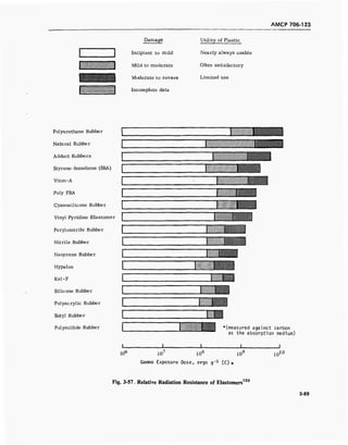
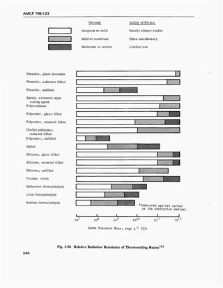
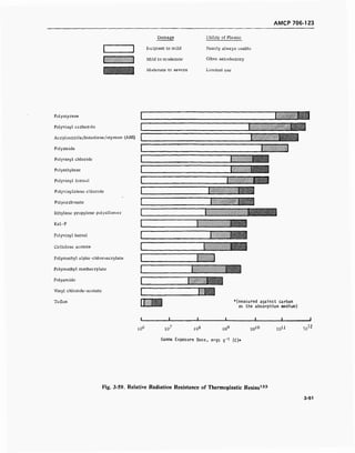
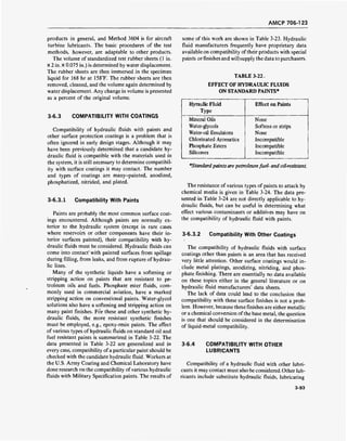
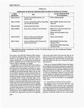
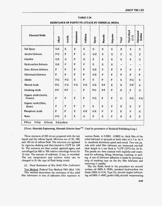
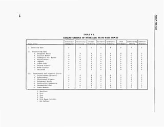
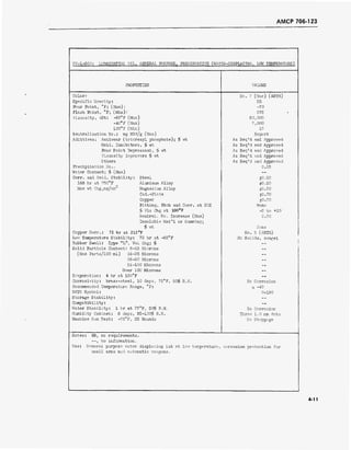
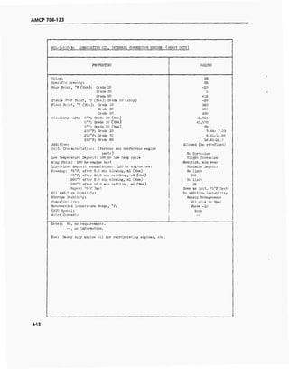
![AMCP 706-123
MI1-H-5606B: HYDRAUIIC FIUID, PETROLEUM BASE, AIRCRAFT, MISSIIE AND ORDNANCE
PROPERTIES VALUES
Color: Red
Pour Point, °F (Max): -75
Flash Point, °F (Min): 200
Vircosity, cSt: -65°F (Max) 3,000
-40°F (Max) 500
130°F (Min) 10
Additives: Antiwear; fa wt 0.50
Oxidation Inhibitors, fa wt S 2.00
Corrosion Inhibitors, fa wt NR
Viscosity Improvers, fa wt s 20.00
Others No Pour Point Dep.
neutralization Ho.: mg KOH/g (Max) 0.20
Precipitation Ho.: (Max) NR
Evaporation: 4 hr at 150°F Oily, nontacky
Corr. and Oxid. Stability: Steel ±0.20
]68 hr at 250°F, Aluminum Alloy +0.20
Max wt Chg , Magnesium ±0.20
mg/cm2
Cad.-Plate +0.20
Copper ±0.60
Pitting, Etch, or Corr. at 20X Hone
Vise Chg at 130°P, fa -5 to +20
Neutral. No. Chg (Max) +0.20
Solid Particle Content: 5-15 Microns 2,500
(Max Part/]00 ml) 16-25 Microns 1,000
26-50 Microns 250
51-100 Microns 25
Over 100 Microns None
Copper Strip Corr.: 72 hr at 250°F (Max) No. 2 (ASTM)
Low Temp Stability: 72 hr at -65°F No Solids, nongel
Rubber Swell: Type "b" Vol Chg, fa 19-28
Foaming:.' After 5.0 min blowing, ml (Max) 65
(at 75°F) After 10.0 min settling, ml (Max) None
Storage Stability: 75°F, months (Min) 12.0
Water Content: (Max) 100 ppm
Recommended Temp. Range, °F : Air (closed) -65/160 (275)
Specific Gravity; NR
Shear Stability: Vise Chg; cSt/l30°F (Max) s -15$
(30 min Sonic Oscil.) Vise Chg; cSt/-40°F (Max) s
Ref. Fluid
Neutral. No. Chg (Max) 2
0.20
NATO Symbol/interchangeable Ifyd. Fluid: H-515/none
Corr. Prot. (bare steel): 100 hr at 120°F, 100$ R.H. NR
Notes: MR, no requirements.
RT, room temperature.
Use: Auto, pilots, shock absorbers, brakes, flap controls, missile servo, and other
systems using synthetic seals.
4-14](https://image.slidesharecdn.com/884519-170327080602/85/Fluid-mechanics-material-187-320.jpg)
![AMCP 706-123
MIL-H-6083C: HYDRAULIC FLUID, PETROLEUM BASE, FOR PRESERVATION AND TESTING
PROPERTIES VALUES
Color: Red (Clear)
Pour Point, °F (Max): -75
Flash point, °F (Min): 200
Viscosity, cSt: -65°F (Max) 3500
-40°F (Max) 800
130°F (Min) 10
Additives: Antiwear; $ wt 0.50
Oxidation Inhibitors, $ wt S 2.00
Corrosion Inhibitors, $ wt Allowed
Viscosity Improvers, % wt 10.0
Others No Pour Point Dep.
Neutralization No.: mg KOH/g (Max) 0.20
Precipitation No.: (Max) 0
Evaporation: 4 hr at 150° F NR
Corr. and Oxid. Stability: Steel +0.20
168 hr at 250°F, Aluminum Alloy +0.20
Max wt Chg, Magnesium ±0.20
mg/cm^ Cad.-Plate ±0.20
Copper +O.60
Pitting, Etch, or Corr. at 20X None
Vise. Chg at 130°F, /» -50 to +20
Neutral. No. Chg (Max) 0.30
Solid Particle Content: 5-15 Microns 2,500
(Max Part/100 ml) 16-25 Microns 1,000
26-50 Microns 250
51-100 Microns 25
Over 100 Microns 5
Copper Strip Corr.: 72 hr at 250°F (Max) No. 3 (ASTM)
Low Temp Stability: 72 hr at -65°F No Solids, nongel
Rubber Swell: Type "L" Vol Chg, j, 19-26.5
Foaming: (75°F) After 5.0 min blowing, ml (Max) 65
After 10.0 min settling, ml (Max) Complete collapse
Storage Stability: 75°F, months (Min) ±u
Water Content:% (Max) 0.05
Recommended Temp Range °F: Air -65/160
Specific Gravity:
r NE
1Shear Stability: Vise Chg; cSt/l30°F (Max) 15,000 pump cycle; Test 1
(30 min Sonic Oscil.) Vise Chg; cSt/-40°F (Max) <L Ref. fluid, MIL-F-5602]
Neutral. No. Chg (Max) ^- +0,30 J
NATO Symbol/interchangeable Hyd. Fluid: C-635/See Note
Corr. Prot. (bare steel): 100 hr at 120°F, 100$ R.H. Trace
Notes: NR, no requirements.
Not interchangeable with castor oil or nonpetroleum b ase oils.
Use: Preservative oil for ord. and aircraft systems, test or flush.
4-15](https://image.slidesharecdn.com/884519-170327080602/85/Fluid-mechanics-material-188-320.jpg)
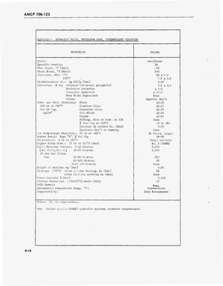
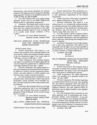
![AMCP 706-123
MIS-10150: HYDRAULIC FLUID, PETROLEUM BASF, LOW TEMPERATUBE, CORROSION PREVENTING
PROPERTIES VALUES
Color:
Specific Gravity:
Pour Point, °F (Max):
Flash Point, °F (Min):
Viscosity, cSt: -90° (Max)
(Max).
(Max)
(Max)
(Min)
(Min)
Neutralization No.
Additives: $ wt;
'F
-80°F
-65°F
-40 °F
130 °F
210 °F
ag KOH/g (Max)
Anti-wear (tricresyl phosphate)
Oxidation Inhibitor
Corrosion Inhibitor
Viscosity Improver
Corr. and Oxid. Stability: Steel
168 hr at 250°F Aluminum Alloy
Max wt Chg, Magnesium Alloy
mg/cm2 Cad.-Plate
Copper
<?o Vise Chg at 130"F
Pitting, Etch or Corr. at 20X
Increase in Neutral. No. (Max)
Insoluble Mat'l or Gumming
Low Temperature Stability: 72 hr at -65°F
Shear Stability: Viscosity Chg at 130°F (Max)
(30 min sonic oscil.) Viscosity Chg at -40°F (Max)
Neutral. No. Chg (Max)
Evaporation: 4 hr at 150°F
Copper Strip. Corr.: 72 hr at 250°F (Max)
Solid Particle Content: 5-15 Micron
(Max Parts/l00 ml) 16-25 Micron
26-50 Micron
51-100 Micron
Over 100 Micron
Foaming: (75°F) after 5.0 min blowing; ml (Max)
after 10,0 min settling; ml (Max)
Rubber Swell: Type "L", Vol Chg, $
Water Content: $ (Max)
Storage Stability: (-80°to 120°F) Months (Min)
Recommended Temperature Range ( °F :
Compatibility Hyd Fluids:(Emergency Only)
NATO Symbol:
Corr. Inhib. (humidity): 20 hr at 72°F (bare steel)
Corrosivity (brass and steel): 10 days at 80°F
Wear (Steel): Shell 4-ball; (2 hr, 167°F,
40 kg 1,200 rpm) Scar Dia
Notes: HR, no requirements.
--, no information.
Use: Auto-pilots, shock absorbers, brakes, flap-control mech.
and other systems using synthetic seals.
0.]
Clear and Transparent
NR
-90
200
800
200
5
2.5
0.20
0.5 +
£ 2.0
As Req'd and Approved
£ 10.0
+0.20
±0.20
+0.20
+0.20
+0.60
-5 to +20
None
0.20
None
No Solids, nongel
< Ref. Fluid
< Ref. Fluid
s
0.20
Oily, nontacky
Ho. 2 (ASTM)
2,500
1,000
250
25
None
65
None
19-28
0.08
12
Low Temperature
None
None
No Corrosion
No Corrosion
< 1.0
missile hyd. servo-control
4-18](https://image.slidesharecdn.com/884519-170327080602/85/Fluid-mechanics-material-191-320.jpg)
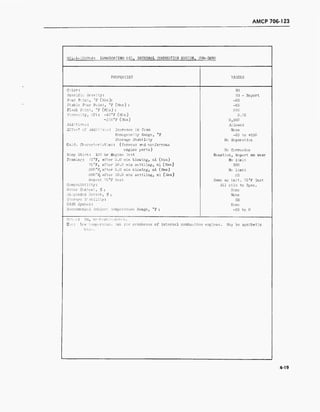
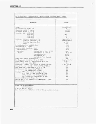
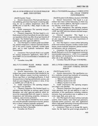
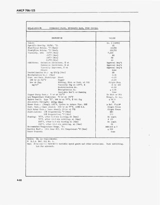
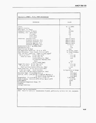
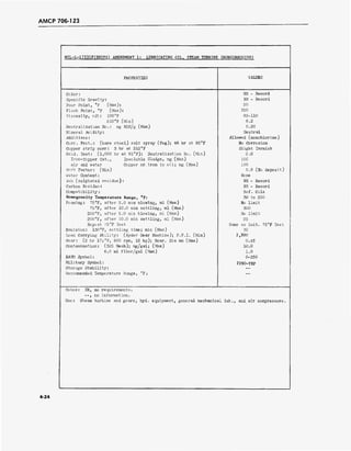
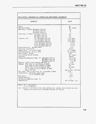
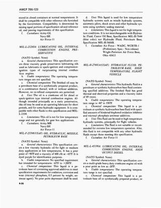
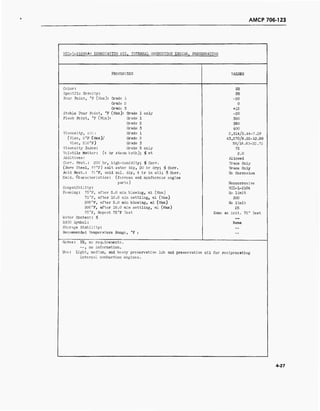
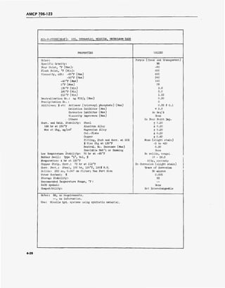
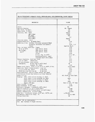
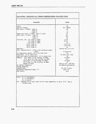
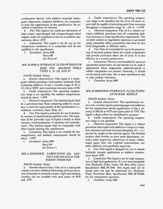
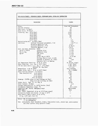
![AMCP 706-123
MIL-H-19457B(SHIPS): HYDRAULIC FLUID, FIRE RESISTANT
Type I Type II
PROPERTIES Low Viscosity High Viscosity
Color: Green Green
Pour Point, °F (Max) : 0 25
Viscosity, cSt: 100°F 43-50 125-135
210° F (Min) 4.8 6.3
Neutrality (Qualitative): Methyl Orange Neutral (Yellow) Neutral (Yellow)
Neutralization No. (Acid): mg KOH/g (Max) 0.10 0.10
Evaporation: 22 hr at 210°F, $ wt Loss (Max) 0.30 0.30
Foaming Tendency: at 75°F No Limit No Limit
Foam Stability: 10 min after collapse, ml foam (Max) 300 300
Emulsion Test: 130°F, Settling time, min (Max) 30 30
Precipitation No.: (90-95°F), ml (Max) 0.01 0.01
Specific Gravity: No Limit (Record] No Limit (Record)
Refractive Index, % at 20°C do Limit (Record] No Limit (Record)
Corrosion: Brass ±0.2 +0.2
7 days at 13 0°F Zinc ±0.2 +0.2
Max wt chg, Steel +0.2 +0.2
mg/cm Aluminum ±0.2 +0.2
Visual Pitting or Etch. None None
Compatibility with Packings: !tny suitable Any suitable
for TCP for TCP
Butyl Rubber Swell: % vol chg ±5.0 of TCP +5.0 of TCP
Fire Resistance: CFR Compression Ratio (Min) 42:1 42;1
Viscosity Shear Stability: Vise chg at 100°F (Max) -10$ -10$
5,000 cycles, 1,000 psi Visual Separation None None
at 100°F Visual Decomposition None None
Sludging None None
Neutralization (Acid) No.:
mg KDH/g (Max) 0.5 0.5
Bearing Lub., 208 Ball Bearing: 4,600 lb & 1,750 rpm (life) £50$ Symbol
2110H
£50$ Symbol 2110H
Hydrolytic Stability: Copper; wt Loss; mg/cm2
(Max) 0.3 0.3
48 hr at 200°F Copper, Visual Corr None None
and 5 rpm Water layer acidity: mg/K0H (Max) 5.0 5.0
Acid No. Chg of Fluid; mg KDH/g
fluid to.2 Max ±0.2 Ma:
Insolubles, $ (Max) 0.5 0.5
Handling Properties: Toxic * Toxic *
NATO Symbol: H-580 None
Recommended Operating Temp Range, °F ; Low- >25 > 40
High 160-210 160-210
Storage Stability: -- —
Compatibility: Other Fluids -- --
■ßase Fluid: Phosphorus Ester Phosphorus Ester
Notes: —, no information.
»Material qualified under MIL-H-19457B(SHIPS) has a low ortho isomer content in order
to pass the specification toxicity requirement. T le Bureau of Medicine and Surgery
has approved the shipboard use of these qualified ]Products as a res ult of careful
consideration by a committee of competent toxlcolo ?ists. Container3 must be properly
marked with warning labels as required by the spec .fication.
Use: Hydraulic systems and air compressors where fire ressistant fluid Is leeded.
4-37](https://image.slidesharecdn.com/884519-170327080602/85/Fluid-mechanics-material-210-320.jpg)
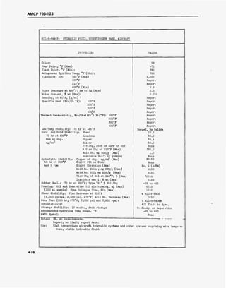
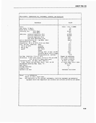
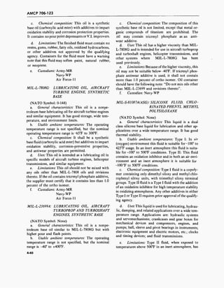
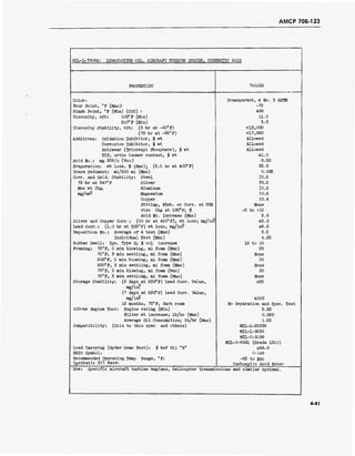
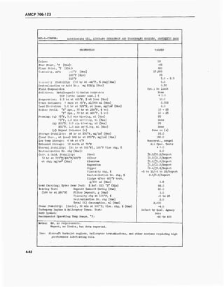
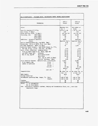
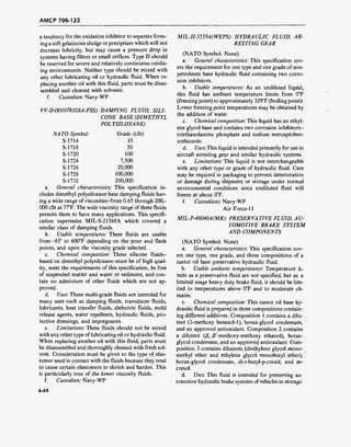
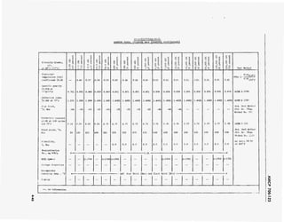
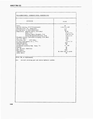
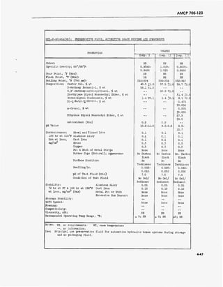
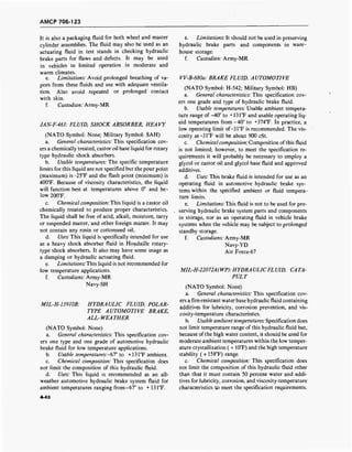
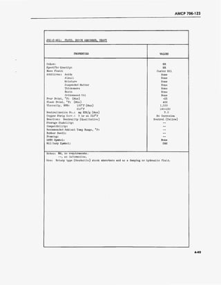
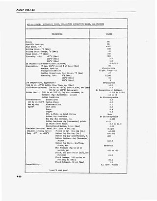
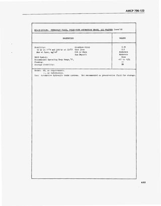
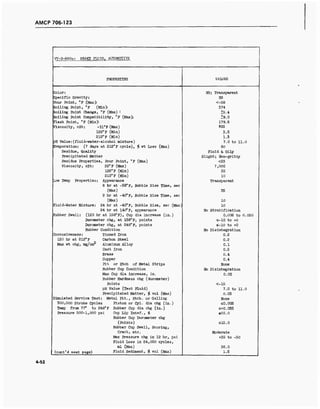
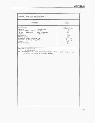
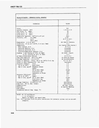
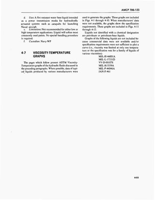
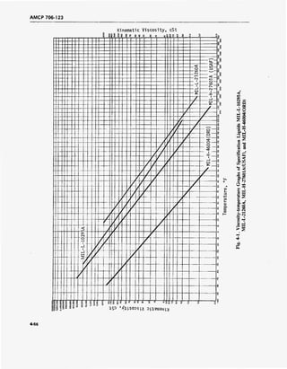
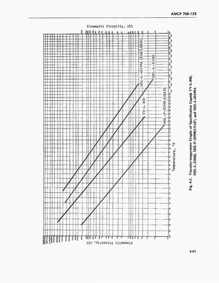
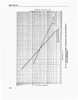
![AMCP 706-123
,
Ki
SI
iema
8
ti
8
c
fi
Viscosity,
8 ? 8 8 £
cSt
eg ss S i
c
. o
8
•
9
s
8
P
Q o
ft
r<
o 3
Z
<s
-H
-H Sr^
i P
ÜH
_] 8
t—<
te-l
<3
S
O
8
8
g
8
p
2
«
o
o
o
8
U>
?
8
—
cQ
3
3
3
O
1
C
i
-1
-1
'
i»
c
M
L
?C
C
C
VI
0
0
1 , >-
f
C
1
ä
8
-4
1 0*
S
II
o c.
11|i i c
S
8C
s c c s(V
o
1 8§ S 8 8
;.L
S
SO
* 8 O
!4
2 o
eiuau j
q o o o
*
c q
a>
s-
+->
ra
i-
a>
Q.
E
QJ
QQ
vo
o
■
■
V)
B
_©
u Q
3 o
O.Z
O iH
■s ^
9» 2
CS g
I- A
Si -
* s
4-59](https://image.slidesharecdn.com/884519-170327080602/85/Fluid-mechanics-material-232-320.jpg)
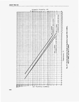
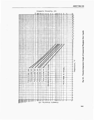

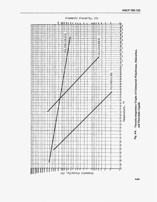
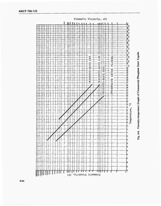
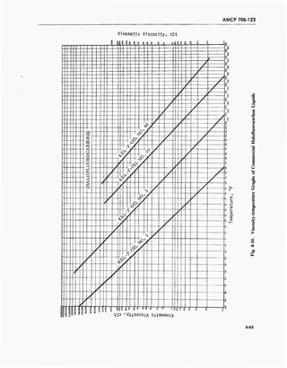
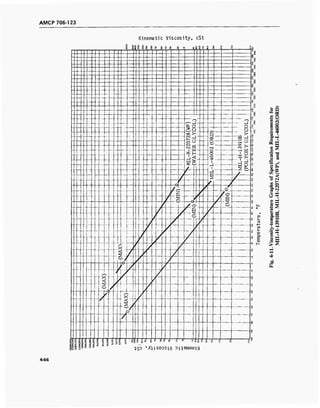
![AMCP 706-123
Kinematic Viscosity, cSt
s? 1 1 O
if § £ s 5 Si 8 £ sS Q C c c O Q O
~9
'
g
o
*
S
B
u
- e
- =i
O
3B]:
z o
^
«
o
oc
- 1
00
1
>o
J C
&
»5
1 9
w 4 <y
^ ] P
J
■1
~K o
-a. —*•
Z / i 1 s
^ ( ) o
•* R
/ / ^ 1 8
r / ^ H
S
J ^
/
1
fj o
1
(6 o
*•■s.
<c
-"■*
i-
A 6
4-1
8
S
<n
J—»-
cd O
o O -
CO £.
^-^ K
X
•D
- Ä
1 "
< /
k
> V.J
- (• >
/ o
■H
/
r
/
/
f
X
— $
sj.
.—. _ g
c f
/
— —,
i?>
IIS °- h
§
§
8o
a
ao
8 c
8c
c
- 1 ft i 8S
IS
S 8
0 '
o
S(3DS"I
8
A
o in 2 °
J3UL>|
q o o
Iß
o. o
3
^s
01
S_
S-
aj
Q-
ai
c
<u
w
S
(/>
« o
B -<
O -<*J r~83 00
C
o1-H
U 90
a. W3
t/3 I-)
<M HH
o
Stf)JS "O
a. S
03 03
b
o r-
fo
9 o
ca t/5
a» h-1
a.
so 03
■ O
>> on
o
© P3o I
V)
>
> >
oc
4-67](https://image.slidesharecdn.com/884519-170327080602/85/Fluid-mechanics-material-240-320.jpg)
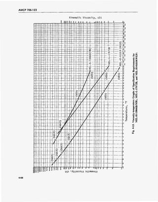
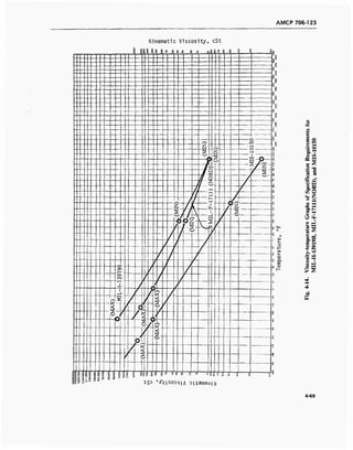
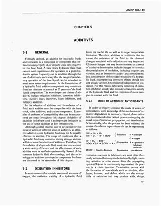
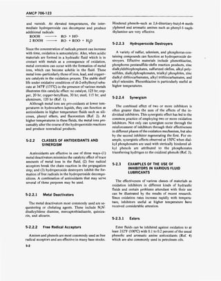
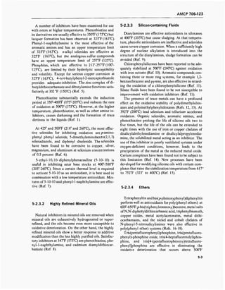
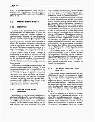
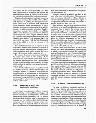
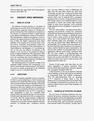
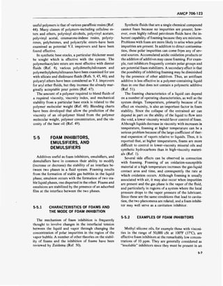
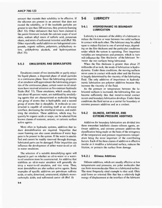
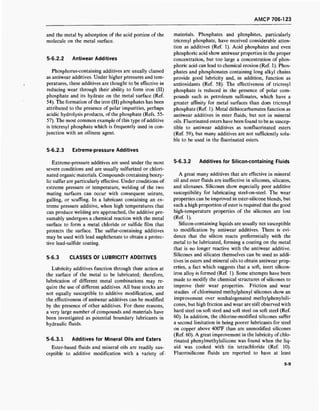
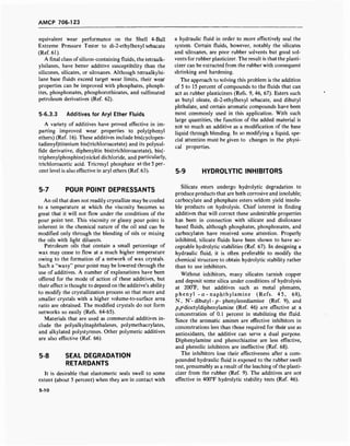
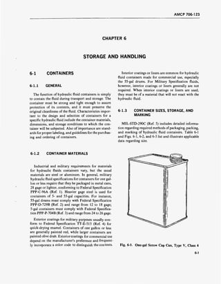
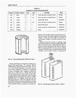
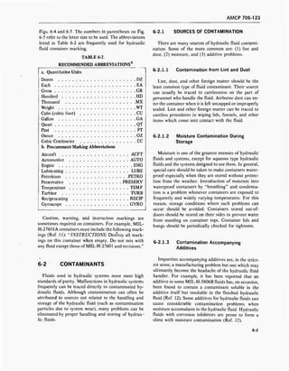
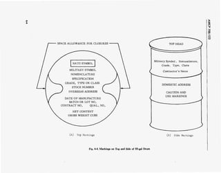

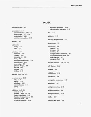


This document provides an overview of hydraulic fluids and hydraulic system components. It discusses the principles of hydraulics and the requirements for hydraulic fluids, including temperature, viscosity, compatibility with system materials, stability, lubricity, and other considerations. It then describes various power transmission equipment used in hydraulic systems, such as pumps, actuators, intensifiers, reservoirs, filters, accumulators, valves, heat exchangers, piping, shock absorbers, and liquid springs. It also covers fluid properties, significance, and test methods for properties like viscosity, low-temperature properties, flammability, volatility, density, lubrication, and more. The document provides a comprehensive reference on hydraulic fluids and system design.