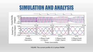
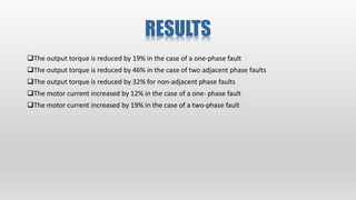
FAULT TOLERANT ANALYSIS OF
FIVE-PHASE PERMANENT
MAGNET SYNCHRONOUS
MOTOR
SUBMITTED TO,
Dr. CHINMAYA K. A.
ASSISTANT PROFFESOR
SUBMITTED BY,
SHILKY KESHARI
(23082035)
TABLE OF
CONTENTS
INTRODUCTION
DESIGN CONSIDERATION
FAULT-TOLERANT CONTROL
TORQUE ESTIMATION
SIMULATION
RESULTS
CONCLUSIONS
REFERENCES
Basics of 5-Phase
PMSM
 It operates on the principle of synchronism, where the rotor and stator magnetic fields
align to create rotation.
 5-Phase PMSMs offer:
 Reduced Torque Ripple
 Improved Torque Characteristics
 Enhanced Efficiency and reliability.
 Better fault tolerance
 They are used in:
 Automotive
 Robotics
 Aerospace
 Renewable Energy
DESIGN CONSIDERATIONS
Five stator winding axes
FAULT TOLERANT CONTROL
 Fault may happen in random number of phases
 We will consider 1 phase and 2 phase fault
Healthy operation phase A open phase A and C open phase A and B open
FAULT TOLERANT CONTROL
The solution of the above condition system is to align the remaining phases symmetrically
by considering some reasonable constraints:
Currents must be sinusoidal.
Each healthy phase must maintain the same current amplitude.
Post fault currents must be symmetrical to avoid zero sequence currents
Σi* = 0 must be satisfied.
FAULT TOLERANT CONTROL
The current vectors are forced to align themselves symmetrically.
In the case of a one‐phase fault, a new set of four current vectors is introduced.
Vector B is set at 45° and each current vector is 90° apart from each other, as shown in Figure
FAULT TOLERANT CONTROL
Two open‐phase faults, the post‐fault motor currents must be reconfigured symmetrically so that the
sum of the currents will be zero.
In doing so, the new current vectors are introduced. These vectors are 120° apart from each other,
similar to the conventional three‐phase system shown
TORQUE ESTIMATION OF A
ONE‐PHASE FAULT
FIGURE : (a) Torque with respect to the offset angle for a one‐phase fault; (b) proposed
solution for a one‐phase fault.
Equation of torque
FIGURE: (a) Torque with respect to the offset angle for two non‐adjacent phase faults; (b)
pro‐ posed solution for two non‐adjacent phase faults.
TORQUE ESTIMATION OF A
TWO‐PHASE FAULT
FIGURE: (a) Torque with respect to the offset angle for two adjacent phase faults; (b)
proposed solution for two adjacent phase faults
SIMULATION AND ANALYSIS
FIGURE: The current profile of a 5‐phase PMSM
SIMULATION AND ANALYSIS
FIGURE: Torque and speed profiles in case of healthy, one‐ and two‐phase fault operation.
RESULTS
The output torque is reduced by 19% in the case of a one‐phase fault
The output torque is reduced by 46% in the case of two adjacent phase faults
The output torque is reduced by 32% for non‐adjacent phase faults
The motor current increased by 12% in the case of a one‐ phase fault
The motor current increased by 19% in the case of a two‐phase fault
CONCLUSION
 A case study was per‐ formed to select an optimum point between the achievable
maximum average torque and minimum ripples in accordance with the application
 This paper has presented effective post‐fault current control strategies to operate a
five‐phase permanent magnet synchronous motor indefinitely.
 The simulation results prove the effectiveness of the proposed fault‐tolerant
solution presented.
REFERENCES
1. Kirtley, J.L.; Banerjee, A.; Englebretson, S. Motors for Ship Propulsion. Proc. IEEE 2015, 103, 2320–2332,
doi:10.1109/JPROC.2015.2487044.
2. Cho, Y.; Lee, S.; Kang, G.; Kim, B. Design and Verification of 200 kW Interior Permanent Magnet Synchronous
Motor for Ship Propulsion. In Proceedings of the 2016 IEEE Conference on Electromagnetic Field Computation
(CEFC), Miami, FL, USA, 13–16 No‐ vember 2016.
3. Yanamoto, T.; Izumi, M.; Yokoyama, M.; Umemoto, K. Electric Propulsion Motor Development for Commercial
Ships in Japan. Proc. IEEE 2015, 103, 2333–2343, doi:10.1109/JPROC.2015.2495134.
4. Dwari, S.; Parsa, L. An optimal control technique for multiphase PM machines under open‐circuit faults. IEEE
Trans. Ind. Electron. 2008, 55, 1988–1995, doi:10.1109/TIE.2008.920643.
5. Mohammadpour, A.; Member, S.; Gandhi, A.; Member, S.; Parsa, L. Design and Control of Fault‐Tolerant
Permanent Magnet Machines. In Proceedings of the 2013 IEEE Workshop on Electrical Machines Design, Control
and Diagnosis (WEMDCD), Paris, France, 11–12 March 2013; pp. 108–116.
6. Kang, M.; Huang, J.; Yang, J.; Liu, D.; Jiang, H. Strategies for the fault‐tolerant current control of a multiphase
machine under open phase conditions. In Proceedings of the 2009 International Conference on Electrical
Machines and Systems, Tokyo, Japan, 15–18 No‐ vember 2009; pp. 4–9, doi:10.1109/ICEMS.2009.5382959.
7. Bianchi, N.; Bolognani, S.; Pré, M.D. Strategies for the fault‐tolerant current control of a five‐phase
permanent‐magnet motor. IEEE Trans. Ind. Appl. 2007, 43, 960–970, doi:10.1109/TIA.2007.900445.
Any questions?

five phase PMSM electrical motor synchronous

  • 1.
    FAULT TOLERANT ANALYSISOF FIVE-PHASE PERMANENT MAGNET SYNCHRONOUS MOTOR SUBMITTED TO, Dr. CHINMAYA K. A. ASSISTANT PROFFESOR SUBMITTED BY, SHILKY KESHARI (23082035)
  • 2.
    TABLE OF CONTENTS INTRODUCTION DESIGN CONSIDERATION FAULT-TOLERANTCONTROL TORQUE ESTIMATION SIMULATION RESULTS CONCLUSIONS REFERENCES
  • 3.
    Basics of 5-Phase PMSM It operates on the principle of synchronism, where the rotor and stator magnetic fields align to create rotation.  5-Phase PMSMs offer:  Reduced Torque Ripple  Improved Torque Characteristics  Enhanced Efficiency and reliability.  Better fault tolerance  They are used in:  Automotive  Robotics  Aerospace  Renewable Energy
  • 4.
  • 5.
    FAULT TOLERANT CONTROL Fault may happen in random number of phases  We will consider 1 phase and 2 phase fault Healthy operation phase A open phase A and C open phase A and B open
  • 6.
    FAULT TOLERANT CONTROL Thesolution of the above condition system is to align the remaining phases symmetrically by considering some reasonable constraints: Currents must be sinusoidal. Each healthy phase must maintain the same current amplitude. Post fault currents must be symmetrical to avoid zero sequence currents Σi* = 0 must be satisfied.
  • 7.
    FAULT TOLERANT CONTROL Thecurrent vectors are forced to align themselves symmetrically. In the case of a one‐phase fault, a new set of four current vectors is introduced. Vector B is set at 45° and each current vector is 90° apart from each other, as shown in Figure
  • 8.
    FAULT TOLERANT CONTROL Twoopen‐phase faults, the post‐fault motor currents must be reconfigured symmetrically so that the sum of the currents will be zero. In doing so, the new current vectors are introduced. These vectors are 120° apart from each other, similar to the conventional three‐phase system shown
  • 9.
    TORQUE ESTIMATION OFA ONE‐PHASE FAULT FIGURE : (a) Torque with respect to the offset angle for a one‐phase fault; (b) proposed solution for a one‐phase fault. Equation of torque
  • 10.
    FIGURE: (a) Torquewith respect to the offset angle for two non‐adjacent phase faults; (b) pro‐ posed solution for two non‐adjacent phase faults. TORQUE ESTIMATION OF A TWO‐PHASE FAULT
  • 11.
    FIGURE: (a) Torquewith respect to the offset angle for two adjacent phase faults; (b) proposed solution for two adjacent phase faults
  • 12.
    SIMULATION AND ANALYSIS FIGURE:The current profile of a 5‐phase PMSM
  • 13.
    SIMULATION AND ANALYSIS FIGURE:Torque and speed profiles in case of healthy, one‐ and two‐phase fault operation.
  • 14.
    RESULTS The output torqueis reduced by 19% in the case of a one‐phase fault The output torque is reduced by 46% in the case of two adjacent phase faults The output torque is reduced by 32% for non‐adjacent phase faults The motor current increased by 12% in the case of a one‐ phase fault The motor current increased by 19% in the case of a two‐phase fault
  • 15.
    CONCLUSION  A casestudy was per‐ formed to select an optimum point between the achievable maximum average torque and minimum ripples in accordance with the application  This paper has presented effective post‐fault current control strategies to operate a five‐phase permanent magnet synchronous motor indefinitely.  The simulation results prove the effectiveness of the proposed fault‐tolerant solution presented.
  • 16.
    REFERENCES 1. Kirtley, J.L.;Banerjee, A.; Englebretson, S. Motors for Ship Propulsion. Proc. IEEE 2015, 103, 2320–2332, doi:10.1109/JPROC.2015.2487044. 2. Cho, Y.; Lee, S.; Kang, G.; Kim, B. Design and Verification of 200 kW Interior Permanent Magnet Synchronous Motor for Ship Propulsion. In Proceedings of the 2016 IEEE Conference on Electromagnetic Field Computation (CEFC), Miami, FL, USA, 13–16 No‐ vember 2016. 3. Yanamoto, T.; Izumi, M.; Yokoyama, M.; Umemoto, K. Electric Propulsion Motor Development for Commercial Ships in Japan. Proc. IEEE 2015, 103, 2333–2343, doi:10.1109/JPROC.2015.2495134. 4. Dwari, S.; Parsa, L. An optimal control technique for multiphase PM machines under open‐circuit faults. IEEE Trans. Ind. Electron. 2008, 55, 1988–1995, doi:10.1109/TIE.2008.920643. 5. Mohammadpour, A.; Member, S.; Gandhi, A.; Member, S.; Parsa, L. Design and Control of Fault‐Tolerant Permanent Magnet Machines. In Proceedings of the 2013 IEEE Workshop on Electrical Machines Design, Control and Diagnosis (WEMDCD), Paris, France, 11–12 March 2013; pp. 108–116. 6. Kang, M.; Huang, J.; Yang, J.; Liu, D.; Jiang, H. Strategies for the fault‐tolerant current control of a multiphase machine under open phase conditions. In Proceedings of the 2009 International Conference on Electrical Machines and Systems, Tokyo, Japan, 15–18 No‐ vember 2009; pp. 4–9, doi:10.1109/ICEMS.2009.5382959. 7. Bianchi, N.; Bolognani, S.; Pré, M.D. Strategies for the fault‐tolerant current control of a five‐phase permanent‐magnet motor. IEEE Trans. Ind. Appl. 2007, 43, 960–970, doi:10.1109/TIA.2007.900445.
  • 17.