This paper presents a microfluidic device designed for high throughput trapping of single cells through hydrodynamic manipulation, eliminating the need for microwells or external forces. A finite element model was developed to optimize the design, demonstrating effective cell trapping based on geometrical parameters and fluid velocity. The simulation results align closely with previous experimental findings, highlighting the device's efficiency and the significance of finite element simulations in cell manipulation research.
![TELKOMNIKA, Vol.16, No.2, April 2018, pp. 883~888
ISSN: 1693-6930, accredited A by DIKTI, Decree No: 58/DIKTI/Kep/2013
DOI: 10.12928/TELKOMNIKA.v16i2.9023 883
Received November 9, 2017; Revised February 26, 2018; Accepted March 20, 2018
Finite Element Simulation of Microfluidic Biochip for
High Throughput Hydrodynamic Single Cell Trapping
Amelia Ahmad Khalili, Mohd Ariffanan Mohd Basri*, Mohd Azhar Abdul Razak
Faculty of Electrical Engineering, Universiti Teknologi Malaysia, 81310 UTM Johor Bahru,
Johor, Malaysia
*Corresponding author, e-mail: ariffanan@fke.utm.my
Abstract
In this paper, a microfluidic device capable of trapping a single cell in a high throughput manner
and at high trapping efficiency is designed simply through a concept of hydrodynamic manipulation. The
microfluidic device is designed with a series of trap and bypass microchannel structures for trapping
individual cells without the need for microwell, robotic equipment, external electric force or surface
modification. In order to investigate the single cell trapping efficiency, a finite element model of the
proposed design has been developed using ABAQUS-FEA software. Based on the simulation, the
geometrical parameters and fluid velocity which affect the single cell trapping are extensively optimized.
After optimization of the trap and bypass microchannel structures via simulations, a single cell can be
trapped at a desired location efficiently.
Keywords: single cell trapping, high throughput, finite element simulation, hydrodynamic, microfluidic
Copyright © 2018 Universitas Ahmad Dahlan. All rights reserved.
1. Introduction
Microfluidics is a rapidly developing area of research, and scientists in the
biotechnology, pharmaceutical and life science industries are continually discovering the wide
range of possibilities the technology can provide. Microfluidics plays important roles in various
emerging biological research and application development, including cellular biology [1,2], lab-
on-a-chip [3-6], organ-on-a-chip [7,8] and synthetic biology [9,10] just to name a few. Recently,
single cell analysis has become increasingly important in the field of cellular biology and medical
research. Conventional cellular analysis usually measures the average response from a whole
cell group. However, bulk measurements may cause misleading interpretations due to cell
heterogeneity [11]. Therefore, the analysis of single cell is required to obtain accurate
information regarding the properties, conditions or functional responses of individual cells.
For analyzing a single cell, the scale of the system must be miniaturized to the single
cell level i.e. the physical dimensions of the systems are in the microscale range. In this light,
microfluidics emerges as a powerful technology in providing an accurate individual cell
manipulation. For achieving single cell analysis in microfluidic devices, trapping of a single cell
is necessary. Currently, various techniques have been employed to trap an individual cell in
microfluidic devices. These techniques include dielectrophoresis (DEP) [12-14], optical tweezers
(OT) [15-16], microwell [17-19], and hydrodynamic trapping [20-23]. Dielectrophoresis uses a
nonuniform electric field to exert a force on a dielectric particle [24] and can be used to
manipulate different types of particles [25]. Although it is a very versatile technique, it requires
polarization of the manipulated object. Moreover, to design the system correctly, the frequency
at which the object will experience positive or negative dielectrophoresis must also be known.
There is also a risk of cell damage from the stress induced by the electrical field or joule heating
if care is not taken when designing the system [26]. Optical tweezers are capable of mobilizing
and trapping cells using a gradient force produced by a focused laser beam [27]. The trapped
cell can be moved freely by the manipulator. Although optical tweezers are a high-precision
technique, it can only be used on a limited number of cells, and the position of the cell needs to
be known in advance. Care must also be taken to avoid absorption of laser light by trapped
cells, since cell may be heated during manipulation due to photothermal effects from the laser
irradiation and this may result in cell damage [28]. Microwell arrays allow random capture of
thousands of cells by gravity forces. Although the throughput of such devices is high and many](https://image.slidesharecdn.com/509023-200824005149/85/Finite-Element-Simulation-of-Microfluidic-Biochip-for-High-Throughput-Hydrodynamic-Single-Cell-Trapping-1-320.jpg)
![TELKOMNIKA, Vol.16, No.2, April 2018, pp. 883~888
ISSN: 1693-6930, accredited A by DIKTI, Decree No: 58/DIKTI/Kep/2013
DOI: 10.12928/TELKOMNIKA.v16i2.9023 883
Received November 9, 2017; Revised February 26, 2018; Accepted March 20, 2018
Finite Element Simulation of Microfluidic Biochip for
High Throughput Hydrodynamic Single Cell Trapping
Amelia Ahmad Khalili, Mohd Ariffanan Mohd Basri*, Mohd Azhar Abdul Razak
Faculty of Electrical Engineering, Universiti Teknologi Malaysia, 81310 UTM Johor Bahru,
Johor, Malaysia
*Corresponding author, e-mail: ariffanan@fke.utm.my
Abstract
In this paper, a microfluidic device capable of trapping a single cell in a high throughput manner
and at high trapping efficiency is designed simply through a concept of hydrodynamic manipulation. The
microfluidic device is designed with a series of trap and bypass microchannel structures for trapping
individual cells without the need for microwell, robotic equipment, external electric force or surface
modification. In order to investigate the single cell trapping efficiency, a finite element model of the
proposed design has been developed using ABAQUS-FEA software. Based on the simulation, the
geometrical parameters and fluid velocity which affect the single cell trapping are extensively optimized.
After optimization of the trap and bypass microchannel structures via simulations, a single cell can be
trapped at a desired location efficiently.
Keywords: single cell trapping, high throughput, finite element simulation, hydrodynamic, microfluidic
Copyright © 2018 Universitas Ahmad Dahlan. All rights reserved.
1. Introduction
Microfluidics is a rapidly developing area of research, and scientists in the
biotechnology, pharmaceutical and life science industries are continually discovering the wide
range of possibilities the technology can provide. Microfluidics plays important roles in various
emerging biological research and application development, including cellular biology [1,2], lab-
on-a-chip [3-6], organ-on-a-chip [7,8] and synthetic biology [9,10] just to name a few. Recently,
single cell analysis has become increasingly important in the field of cellular biology and medical
research. Conventional cellular analysis usually measures the average response from a whole
cell group. However, bulk measurements may cause misleading interpretations due to cell
heterogeneity [11]. Therefore, the analysis of single cell is required to obtain accurate
information regarding the properties, conditions or functional responses of individual cells.
For analyzing a single cell, the scale of the system must be miniaturized to the single
cell level i.e. the physical dimensions of the systems are in the microscale range. In this light,
microfluidics emerges as a powerful technology in providing an accurate individual cell
manipulation. For achieving single cell analysis in microfluidic devices, trapping of a single cell
is necessary. Currently, various techniques have been employed to trap an individual cell in
microfluidic devices. These techniques include dielectrophoresis (DEP) [12-14], optical tweezers
(OT) [15-16], microwell [17-19], and hydrodynamic trapping [20-23]. Dielectrophoresis uses a
nonuniform electric field to exert a force on a dielectric particle [24] and can be used to
manipulate different types of particles [25]. Although it is a very versatile technique, it requires
polarization of the manipulated object. Moreover, to design the system correctly, the frequency
at which the object will experience positive or negative dielectrophoresis must also be known.
There is also a risk of cell damage from the stress induced by the electrical field or joule heating
if care is not taken when designing the system [26]. Optical tweezers are capable of mobilizing
and trapping cells using a gradient force produced by a focused laser beam [27]. The trapped
cell can be moved freely by the manipulator. Although optical tweezers are a high-precision
technique, it can only be used on a limited number of cells, and the position of the cell needs to
be known in advance. Care must also be taken to avoid absorption of laser light by trapped
cells, since cell may be heated during manipulation due to photothermal effects from the laser
irradiation and this may result in cell damage [28]. Microwell arrays allow random capture of
thousands of cells by gravity forces. Although the throughput of such devices is high and many](https://image.slidesharecdn.com/509023-200824005149/75/Finite-Element-Simulation-of-Microfluidic-Biochip-for-High-Throughput-Hydrodynamic-Single-Cell-Trapping-1-2048.jpg)
![ ISSN: 1693-6930
TELKOMNIKA Vol. 16, No. 2, April 2018 : 883 – 888
884
cells can be trapped in an array-based format, precise geometrical optimizations are required in
designing the microwells to achieve a high trapping efficiency [17]. In this method cells are not
actively held inside the traps and the following chemical rinsing step may remove the cells from
the bottom of the microwells. Hydrodynamic trapping systems are based on the use of
differential fluidic resistances, where fluidic streamlines transport single cells into each trap.
Once a cell is captured by a trap, the cell body diverts the streamlines to exclude subsequent
cells. In comparison to other methods, hydrodynamic trapping has shown advantages of ease of
operation, high biocompatibility, and high trapping efficiency without the need for surface
modifications or external forces. Although hydrodynamic technique has recorded success in
trapping cells, further parameter investigation and optimization on cellular trapping efficiencies
are still requested [29].
In this study, a proof of concept demonstration for a cell positioning platform using
hydrodynamic manipulation to trap a single cell is presented. The proposed microfluidic device
consists of a series of trap and bypass microchannel structures for efficient and reliable cell
trapping. Selecting appropriate geometrical parameters and obtaining the fluid velocity are
helpful to ensure efficient trapping of cells. By using the optimal design parameter selection of
the device, individual cells could be trapped efficiently without the need for surface modification,
external electric force, or robotic equipment. To fulfill this requirement, a finite element
simulation model to study the hydrodynamic trapping of cells in the microfluidic device is
created. Then, the simulations are conducted to evaluate the cells trapping efficiencies for
various geometrical parameters. The results obtained from the finite element simulation model
show a very good agreement with the previously published experimental results by Tan and
Takeuchi [21], which highlighted the value of finite element simulations in predicting and
investigating the movement of cells in the microfluidic device. The simulation set-up discussed
in this paper can provide some significant guidelines for new biochip design and optimization.
2. Research Method
2.1. Hydrodynamic Trapping Mechanism
The proposed device employs fluidic resistance engineering to perform hydrodynamic
trapping of single cell. To explain this mechanism, the possible flow paths of a single cell are
schematically presented in Figure 1. In Figure 1A the arrow is going to the trapping path and in
Figure 1B the arrow is going to the bypassing path. Here trapping is defined as a single cell
flowing into the trap, and bypassing is defined as the flow of subsequent cell through the
channels next to the trap.
In order to trap the cell as shown in Figure 1, the trap array geometry should be
designed so that the trapping path for an empty trap has a lower flow resistance than the
bypassing path. Then during the loading process, a cell in the fluid is most likely to move into an
empty trap (Figure 1A). However, once the trap is loaded by a cell, the flow resistance in
trapping path dramatically increases and is much larger than that in bypassing path, and thus
subsequent cell bypass the filled trap as shown in Figure 1B.
Figure 1. Schematic illustration of the flow hydrodynamic resistance in the microchannel for two
different conditions (A) empty trap channel (before cell trapping occurs); (B) after cell has been
trapped.](https://image.slidesharecdn.com/509023-200824005149/85/Finite-Element-Simulation-of-Microfluidic-Biochip-for-High-Throughput-Hydrodynamic-Single-Cell-Trapping-2-320.jpg)
![TELKOMNIKA ISSN: 1693-6930
Finite Element Simulation of Microfluidic Biochip for High Throughput… (Amelia Ahmad Khalili)
885
The flow within a microfluidic device is determined by the pressure drop across the two ends of
the microchannel, as defined by the following Equation:
( ) (1)
where ∆P is the pressure drop, Rh is the hydrodynamic flow resistance of the rectangular
microchannels, μ is the fluid viscosity, L, H and W are length, height and width of the channel
respectively. By using a relationship of A = W × H and P = 2(W + H), the hydrodynamic flow
resistance can be formulated in the following equation:
(2)
where C denotes a constant that depends on the aspect ratio (H/W), A is the cross-sectional
area and P is the perimeter of the channel. The flow rate ratio between trap path and main path
can be modelled as given in the following equation:
( ) ( ) ( ) (3)
For the trap to work, the flow rate along trap path must be greater than that of main path
(QTrap>QMain).
In this section, it is explained the results of research and at the same time is given the
comprehensive discussion. Results can be presented in figures, graphs, tables and others that
make the reader understand easily [2],[5]. The discussion can be made in several sub-chapters.
2.2. Simulation Setup
The analysis is carried out using finite element ABAQUS-FEA analysis software which
can perform multiphysics analysis. The single cell trapping model consists of two different parts;
Eulerian part as the fluid channel and a three dimension (3D) deformable part as the sphere-
shaped elastic cell model as shown in Figure 2A-2B. The fluid consists of two microchannels,
the main channel and trap channel with a rectangular trap hole is placed in the center, at the
edge of the trap channel. The microchannel is modelled as 3D Eulerian explicit EC3DR and an
8-node linear Eulerian brick element part assigned with water properties (density, equation of
state, and viscosity). A sphere-shaped cell (5 µm in diameter) is modelled as an elastic 3D
standard solid deformable C3D8R and an 8-node linear brick 3D part.
Figure 2C shows the assembly setup with a cell positioned in the main channel, near
the channel’s inlet (left). The parts are assembled to develop the finite element model for the
proposed system as shown in Figure 2C. The initial position of cell is fixed to the same position
(distance between cell and trap channel) for all the models used. Interaction between objects
and water are set as general contact with rough tangential behaviour and the interaction
between cell surface and channel’s wall is set as frictionless. The fluid channel and cell is
meshed using hexahedron and tetrahedron mesh types, respectively. Total mesh elements for
the cell trapping model ranged from 10627 to 22485 elements. No-inflow and non-reflecting
outflow Eulerian boundary conditions are applied to the channel’s wall. Constant inflow velocity
of 0.5 µms-1 is applied to the inlet and atmosphere pressure is applied to the outlet of the
channel for all the models analyzed.](https://image.slidesharecdn.com/509023-200824005149/85/Finite-Element-Simulation-of-Microfluidic-Biochip-for-High-Throughput-Hydrodynamic-Single-Cell-Trapping-3-320.jpg)
![TELKOMNIKA ISSN: 1693-6930
Finite Element Simulation of Microfluidic Biochip for High Throughput… (Amelia Ahmad Khalili)
887
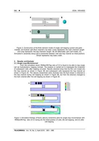
3.2. High Throughput Microchannel
The simulation results show that high throughput microchannel with RhMain/RhTrap
ratio of 3.5 is able to trap single cells using the hydrodynamic trapping concept. Results
obtained show that the first cell moved into the first trap channel and subsequent cells bypassed
the first trap channel to be trapped into the following trap channel as shown in Figure 4B.
A B
Figure 4. Simulation findings of fluid’s velocity streamline plots for high throughput microchannel
with RhMain/RhTrap ratio of 3.5 during (A) the initial position of cells; (B) cell trapping.
4. Conclusion
In this study, a proof of concept demonstration for a cell positioning platform using
hydrodynamic manipulation to trap single cells in high throughput manner is presented.
Selecting appropriate geometrical parameters and obtaining the fluid velocity are helpful to
ensure efficient trapping of cells. By using the optimal design parameter selection of the device,
individual cells could be trapped efficiently. A finite element simulation model to study the
hydrodynamic trapping of cells in the microfluidic device is created. The results obtained from
the finite element simulation model show a very good agreement with the previously published
experimental results which highlighted the value of finite element simulations in predicting and
investigating the movement of cells in the microfluidic device.
Acknowledgement
This work is supported by Ministry of Higher Education (MOHE) Malaysia under the
Fundamental Research Grant Scheme (FRGS) (R.J130000.7823.4F761).
References
[1] Kim, D, Wu, X, Young, AT, Haynes, CL. Microfluidics-based in Vivo mimetic systems for the study of
cellular biology. Accounts of chemical research. 2014; 47(4): 1165-1173.
[2] Velve-Casquillas, G, Le Berre, M, Piel, M, Tran, PT. Microfluidic tools for cell biological research.
Nano Today. 2010; 5(1): 28-47.
[3] Haeberle, S, Zengerle, R. Microfluidic platforms for lab-on-a-chip applications. Lab on a Chip. 2007;
7(9): 1094-1110.
[4] Dutse, SW, Yusof, NA. Microfluidics-based lab-on-chip systems in DNA-based biosensing: An
overview. Sensors. 2011; 11(6): 5754-5768.
[5] Pawinanto, RE, Yunas, J, Majlis, B, Hamzah, A. (2016). Design and Fabrication of Compact MEMS
Electromagnetic Micro-Actuator with Planar Micro-Coil Based on PCB. TELKOMNIKA
(Telecommunication Computing Electronics and Control). 14(3): 856-866.
[6] Rusli, MQA, Chee, PS, Leow, PL. Characterization of electromagnetic valvelessmicropump.
TELKOMNIKA (Telecommunication Computing Electronics and Control). 2017; 15(2): 771-777.
[7] Jiang, B, Zheng, W, Zhang, W, Jiang, X. Organs on microfluidic chips: A mini review. Science China
Chemistry. 2014; 57(3): 356-364.](https://image.slidesharecdn.com/509023-200824005149/85/Finite-Element-Simulation-of-Microfluidic-Biochip-for-High-Throughput-Hydrodynamic-Single-Cell-Trapping-5-320.jpg)
![ ISSN: 1693-6930
TELKOMNIKA Vol. 16, No. 2, April 2018 : 883 – 888
888
[8] Bhise, N S, Ribas, J, Manoharan, V, Zhang, YS, Polini, A, Massa, S, Dokmeci, MR, Khademhosseini,
A. Organ-on-a-chip platforms for studying drug delivery systems. Journal ofControlled Release.2014;
190; 82-93.
[9] Vinuselvi, P, Park, S, Kim, M, Park, JM, Kim, T, Lee, SK. Microfluidic technologies for synthetic
biology. International journal of molecular sciences. 2011; 12(6): 3576-3593.
[10] Gulati, S, Rouilly, V, Niu, X, Chappell, J, Kitney, RI, Edel, JB, Freemont, PS. Opportunities for
microfluidic technologies in synthetic biology. Journal ofthe Royal Society Interface. 2009; 6(Suppl 4):
S493-S506.
[11] Altschuler, SJ, Wu, LF. Cellular heterogeneity: do differences make a difference? Cell. 2010; 141(4):
559-563.
[12] Voldman, J, Gray, ML, Toner, M, Schmidt, MA. (2002). A microfabrication-based dynamic array
cytometer. Analytical Chemistry. 74(16): 3984-3990.
[13] Thomas RS,Morgan H, Green NG. Negative DEP traps for single cell immobilisation. Lab on a Chip.
2009; 9(11): 1534-1540.
[14] Gray DS, Tan JL, Voldman J, Chen, CS. Dielectrophoretic registration of living cells to a
microelectrode array. Biosensors and Bioelectronics. 2004; 19(7): 771-780.
[15] Huang KW, Su TW, Ozcan A, Chiou,PY. Optoelectronic tweezers integrated with lensfree holographic
microscopy for wide-field interactive cell and particle manipulation on a chip. Lab on a Chip. 2013;
13(12): 2278-2284.
[16] Xie Y, Zhao C, Zhao Y, Li S, Rufo J, Yang S, Guo F, Huang TJ. Optoacoustic tweezers: a
programmable,localized cell concentrator based on opto-thermally generated, acoustically activated,
surface bubbles. Lab on a Chip. 2013; 13(9): 1772-1779.
[17] Rettig JR, Folch A. Large-scale single-cell trapping and imaging using microwell arrays. Analytical
Chemistry. 2005; 77(17): 5628-5634.
[18] Tang J, Peng R, Ding J. The regulation of stem cell differentiation by cell-cell contact on
micropatterned material surfaces. Biomaterials. 2010; 31(9): 2470-2476.
[19] Doh, J, Kim, M, Krummel,MF. Cell-laden microwells for the study of multicellularity in lymphocytefate
decisions. Biomaterials. 2010; 31(12): 3422-3428.
[20] Lee PJ, Hung PJ, Shaw R, Jan L, Lee LP. Microfluidic application-specific integrated device for
monitoring direct cell-cell communication via gap junctions between individual cell pairs. Applied
Physics Letters. 2005; 86(22): 223902.
[21] Tan WH, Takeuchi S. A trap-and-release integrated microfluidic system for dynamic
microarrayapplications. Proceedings of the National Academy of Sciences. 2007; 104(4): 1146-1151.
[22] Frimat JP, Becker M, Chiang YY, Marggraf U, Janasek D, Hengstler JG, Franzke J, West J. A
microfluidic array with cellular valving for single cell co-culture. Lab on a Chip. 2011; 11(2): 231-237.
[23] Chung K, Rivet CA, Kemp ML, Lu H. Imaging single-cell signaling dynamics with a deterministic high-
density single-cell trap array. Analytical Chemistry. 2011; 83(18): 7044-7052.
[24] Washizu M. Biological applications ofelectrostatic surface field effects. Journal of electrostatics. 2005;
63(6): 795-802.
[25] Shafiee H, Sano MB, Henslee EA, Caldwell JL, Davalos RV. Selective isolation of live/dead cells
using contactless dielectrophoresis (cDEP). Lab on a Chip. 2010; 10(4): 438-445.
[26] Menachery A, Pethig R. Controlling cell destruction using dielectrophoretic forces. In IEEE
Proceedings-Proceedings of Nanobiotechnology. 2005: 145-149.
[27] Grier DG. A revolution in optical manipulation. Nature. 2003; 424(6950), 810-816.
[28] Foo JJ, Liu KK, Chan V. Thermal effect on a viscously deformed liposome in a laser trap. Annalsof
Biomedical Engineering. 2003; 31(3): 354-362.
[29] Kobel S, Valero A, Latt J, Renaud P, Lutolf M. Optimization of microfluidic single cell trapping for long-
term on-chip culture. Lab on a Chip. 2010; 10(7): 857-863.](https://image.slidesharecdn.com/509023-200824005149/85/Finite-Element-Simulation-of-Microfluidic-Biochip-for-High-Throughput-Hydrodynamic-Single-Cell-Trapping-6-320.jpg)