This document provides an operator's manual for an INMARSAT-C terminal. It describes the system configuration, operational overview of the terminal and its components, procedures for system initialization and setup, file operations, INMARSAT communications functions, data reporting and polling, distress operations, and other functions. It also covers maintenance, troubleshooting, and contains appendices with a menu tree and list of messages.


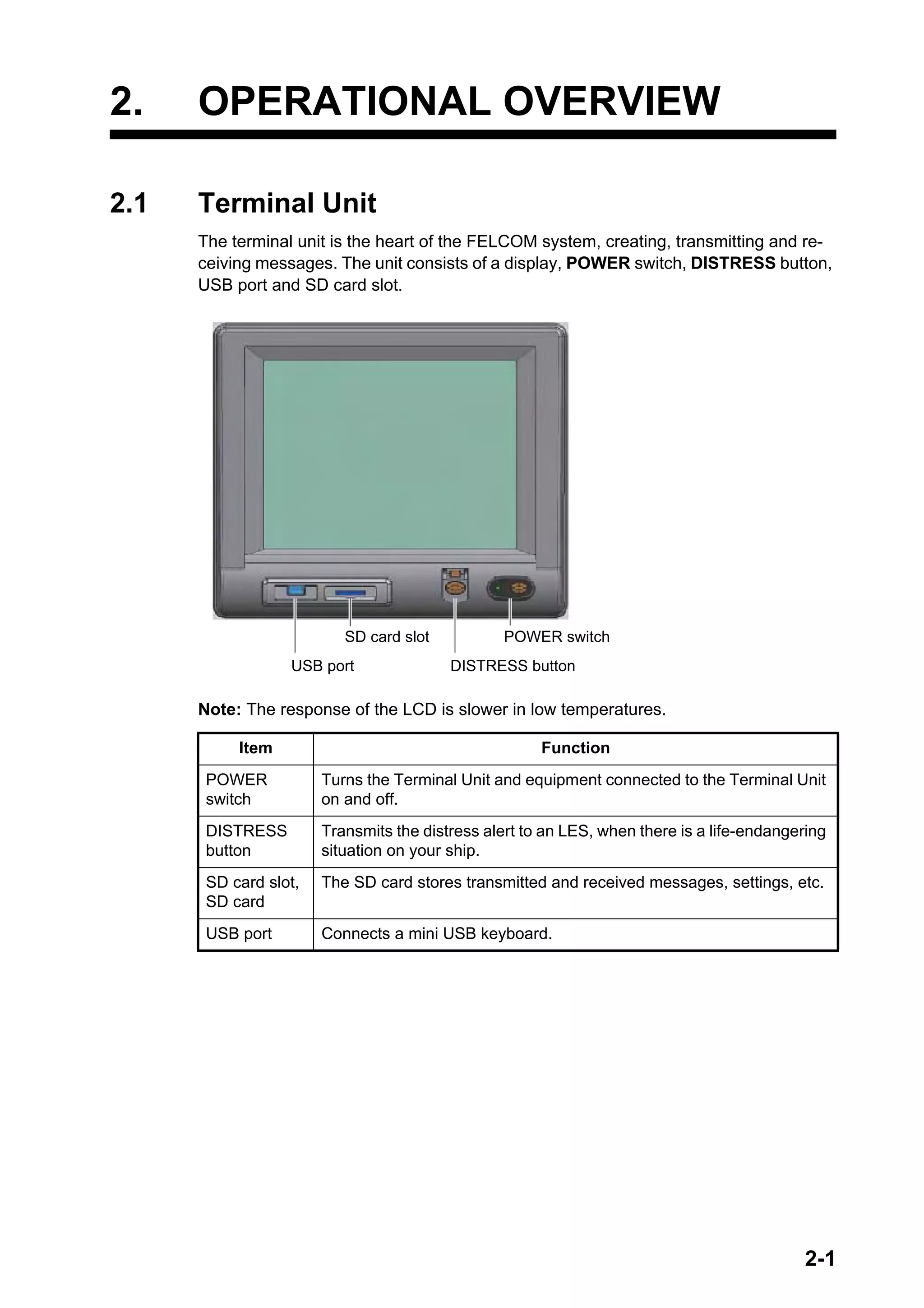
![2. OPERATIONAL OVERVIEW
2-3
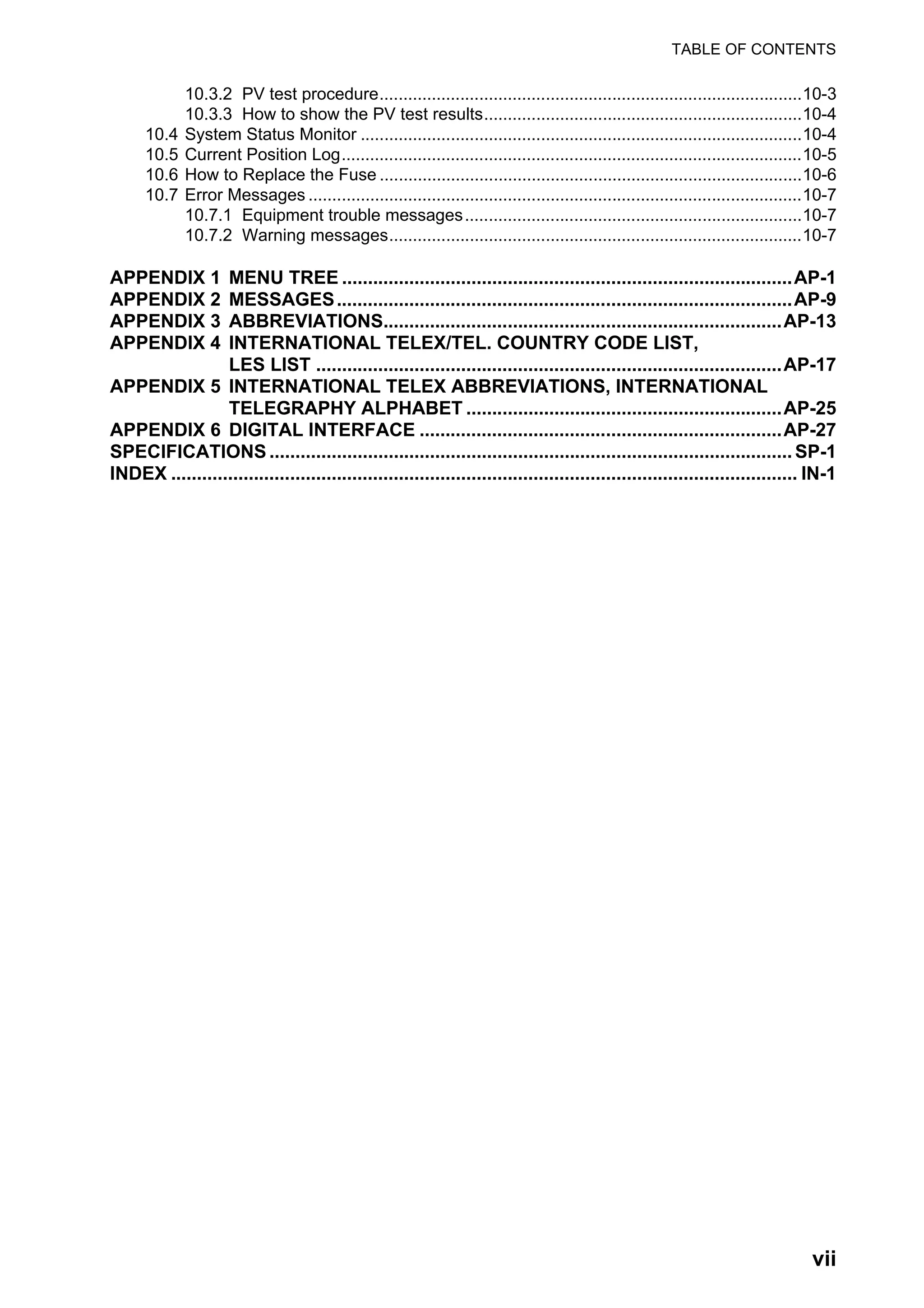
2.2.1 Key description
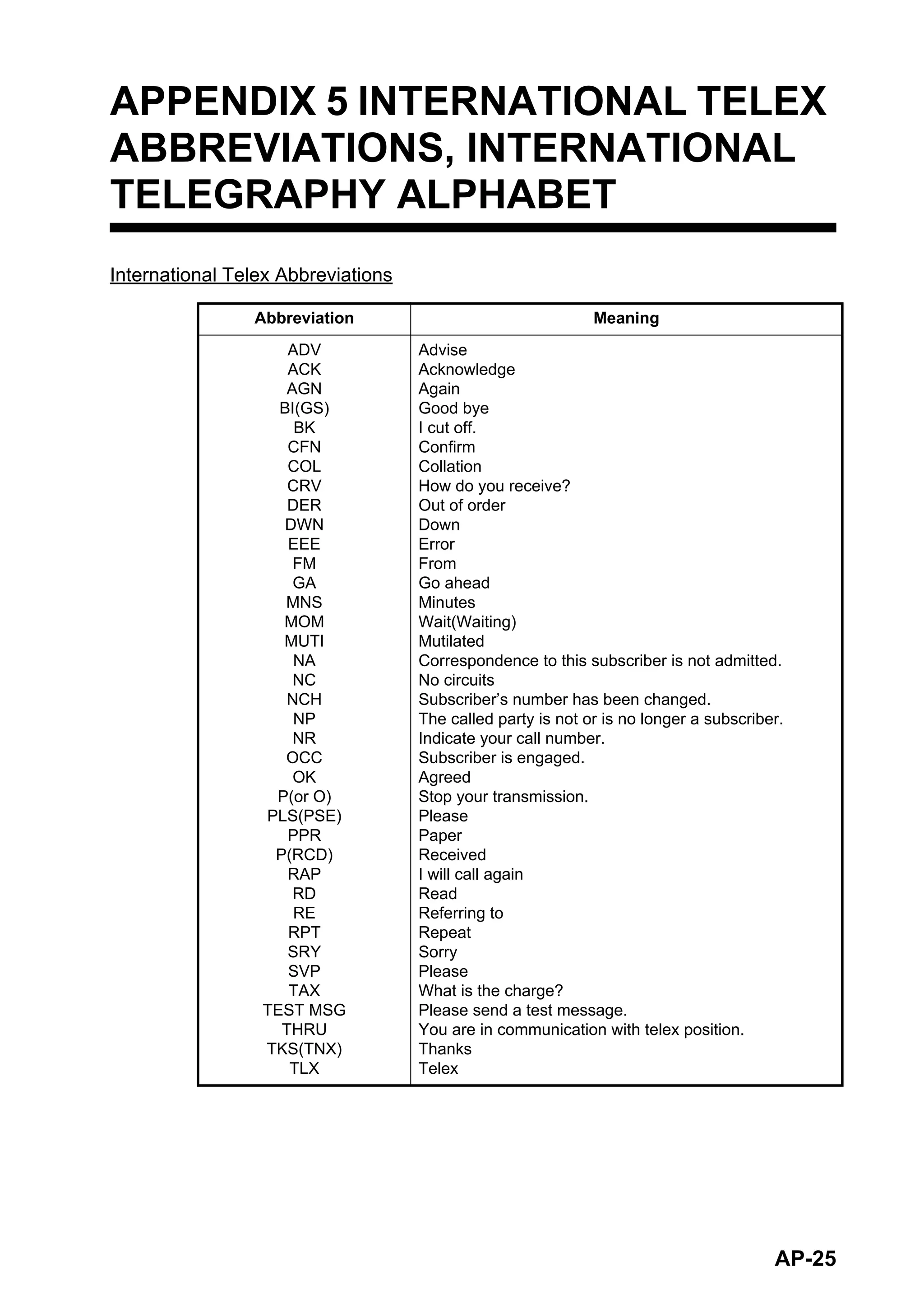
Note: In telex, lower case, #, &, *, $, @, %, etc. are not permitted. A full list of charac-
ters usable in telex appears in the Appendix. For e-mail all characters and symbols
may be used.
Key Function
Esc • Cancels key input and returns to previous display screen.
• Long push to return to the standby display.
F1 - F10 Select menus. See section 2.2.3.
BackSpace Deletes the character to the left of the cursor.
Insert Works the same as “paste.” See “How to cut and paste text” in
section 4.2.4.
Delete Deletes the character selected with the cursor.
Home Moves the cursor to the top of the message being edited.
End Moves the cursor to the bottom of the message being edited.
Page Up Goes to the previous page of the edit screen.
Page Down Goes to the next page of the edit screen.
↑, ↓, ←, → Control the cursor.
Enter Registers key input; inserts carriage return in TX message.
Shift Selects upper or lower case alphabet. Press and hold down the key
and then press the [Caps Lock] key to get upper or lower case alpha-
bet. Note that only upper case alphabet are used in telex.
Alt Provides the shortcut key operation when combined with an alphabet
key. See section 2.2.2.
Spacebar Inserts a space. In addition, it displays the file list, a partial view of a
file, etc., depending on menu.
Caps Lock Turns upper case alphabet input on or off. The Caps Lock LED lights
when upper case alphabet input is on.
Tab Inserts horizontal tab characters. The number of tab characters the
key can insert per line of text can be programmed for two, four or eight
tabs.
Ctrl Works in combination with alphabet keys as follows:
• Ctrl + [M]: Same as Enter.
• Ctrl + [H]: Same as Back Space.
• Ctrl + [I]: Same as Insert.
• Ctrl + [V]: Same as Overwrite+Insert on Edit Mode in the Editor Set-
up menu.
NumLk Turns numeric input on or off. Note that you cannot enter alphabet
when the NumLk LED is lit.](https://image.slidesharecdn.com/felcom-18ome56740a2-220309163554/75/Felcom-18-ome56740-a_2-19-2048.jpg)
![2. OPERATIONAL OVERVIEW
2-4
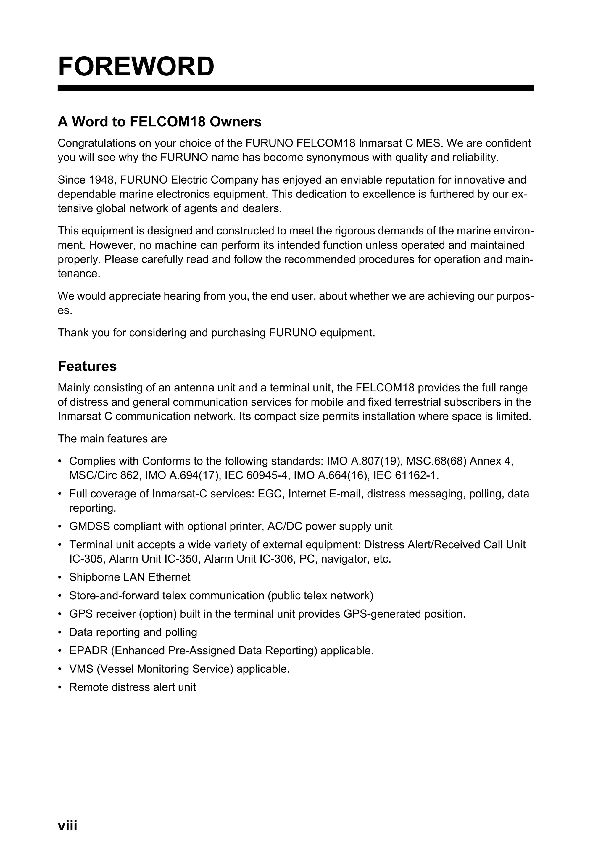
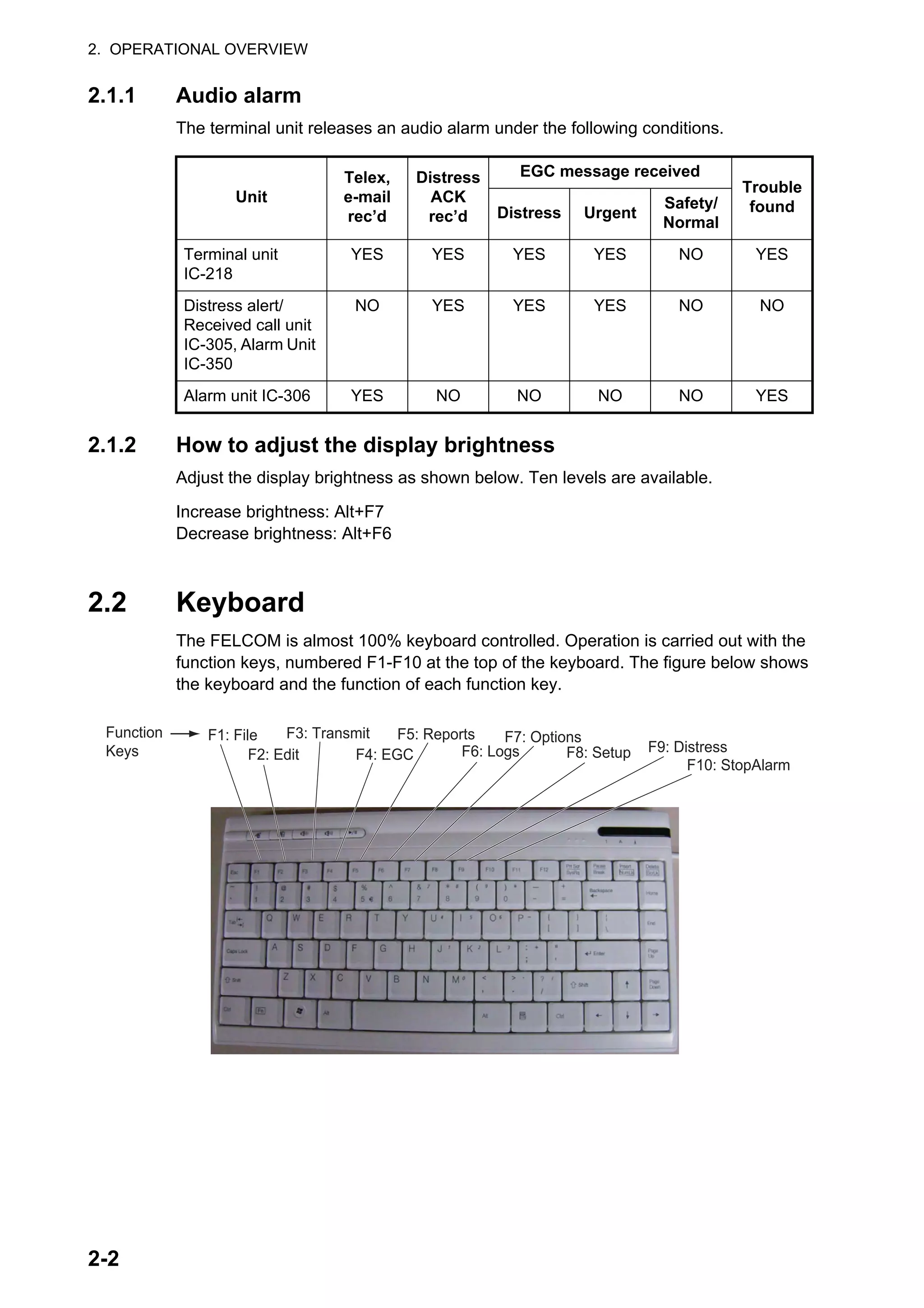
2.2.2 Shortcut keys
The FELCOM provides the keyboard shortcuts shown below for commonly used func-
tions.
2.2.3 Function keys
The function keys are labeled F1-F10 on the keyboard and they provide the functions
shown in the table below. If you get lost in operation, you can return to the standby
display by long pressing the Esc key.
Shortcut key Function
Alt+N Same as [New] in [File] menu.
Alt+O Same as [Open] in [File] menu.
Alt+Q Same as [Close] in [File] menu.
Alt+D Same as [Delete] in [File] menu.
Alt+S Save as [Save] in [File] menu.
Alt+P Save as [Print] in [File] menu.
Alt+X Same as [Undo] in [Edit] menu; undo last [Cut], [Paste].
Delete Same as [Cut] in [Edit] menu.
Alt+C Same as [Copy] in [Edit] menu.
Insert Same as [Paste] in [Edit] menu.
Alt+V Same as [Change Window] in [Edit] menu.
Menu (key) Function
File (F1) Opens and closes file; print files; MIME decoding.
Edit (F2) Text editing facilities (copy, paste, search and replace, etc.).
Transmit (F3) Transmit messages; request delivery status.
EGC (F4) Display EGC messages; show EGC network ID.
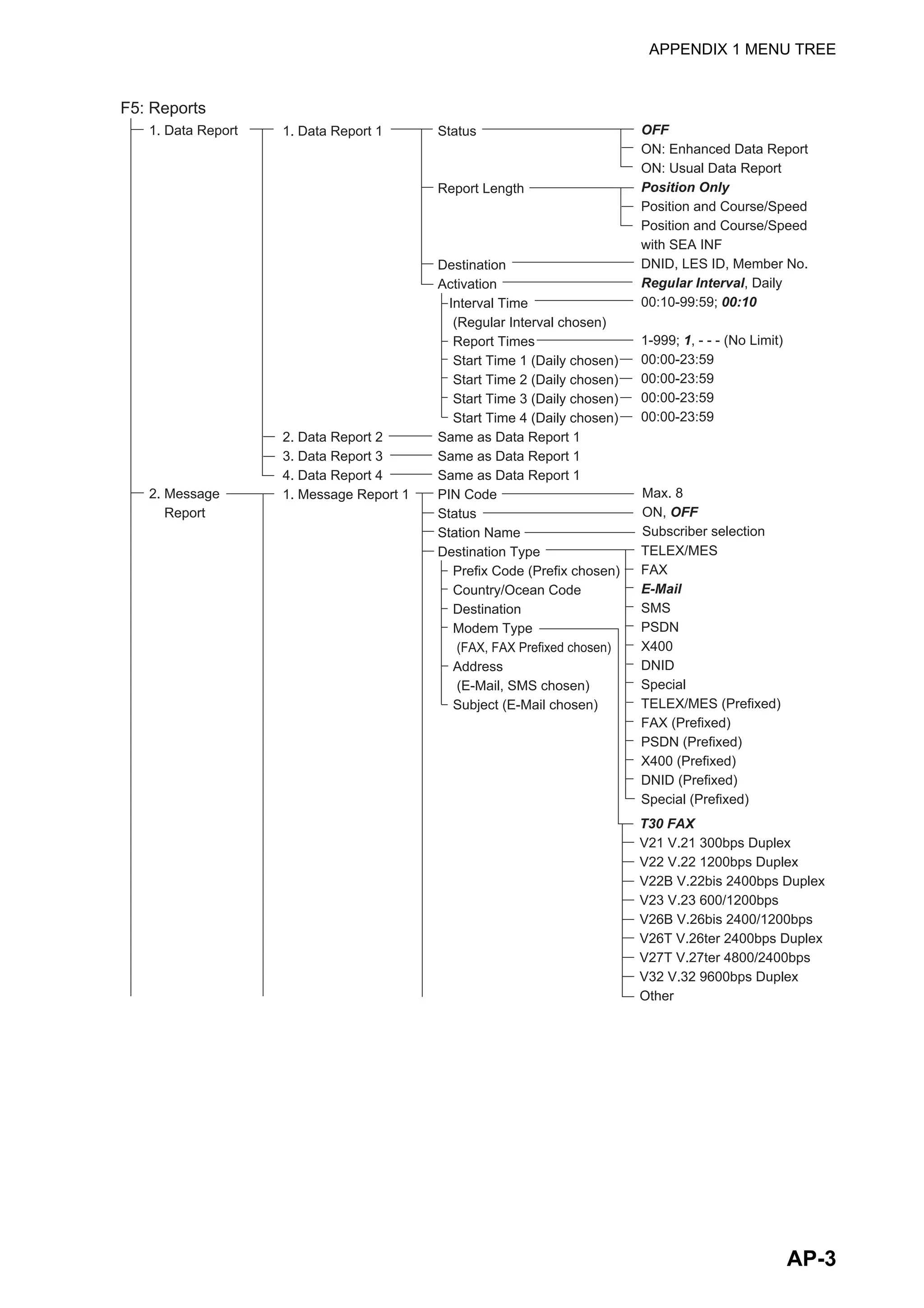
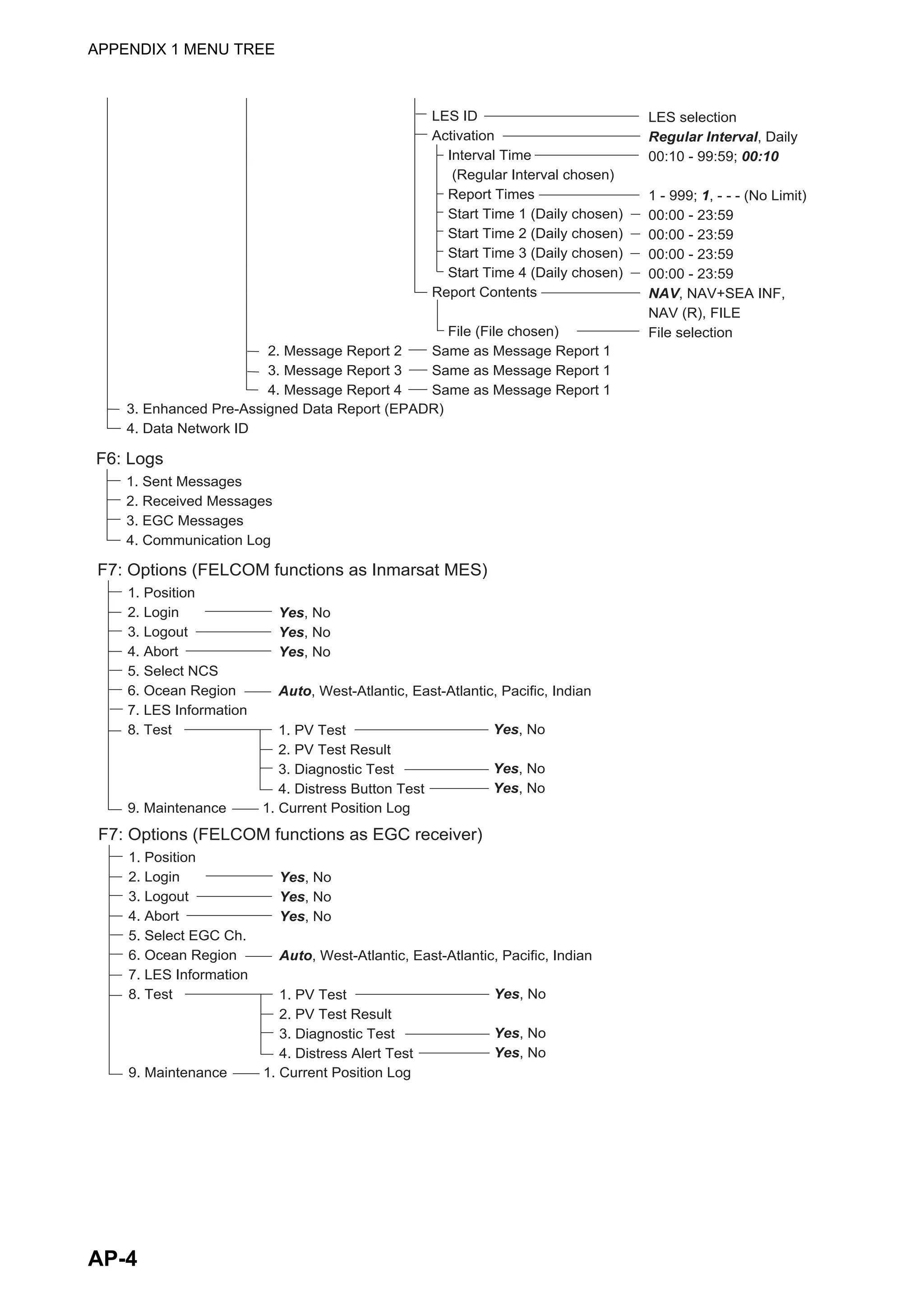
Reports (F5) Facilities for data reporting, message reporting, and EPADR.
Logs (F6) Display logs for sent and received messages, EGC messages;
show the communications log.
Options (F7) Facilities for login and logout, manual position input, testing,
maintenance, NCS and ocean region selection.
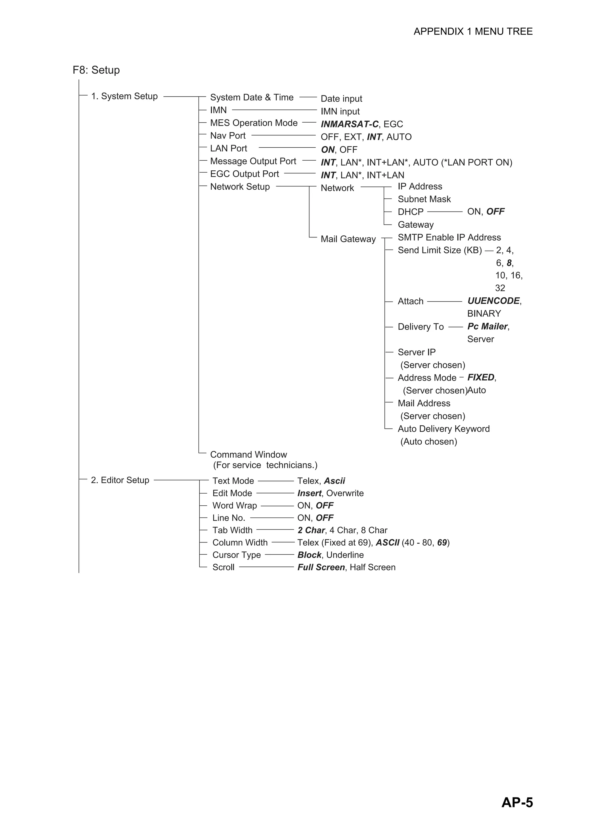
Setup (F8) Menus for system setup, editor setup, EGC setup, auto mode set-
up, e-mail setup, and configuration.
Distress (F9) Prepare the distress alert message.
StopAlarm (F10) Silence audio alarm.](https://image.slidesharecdn.com/felcom-18ome56740a2-220309163554/75/Felcom-18-ome56740-a_2-20-2048.jpg)
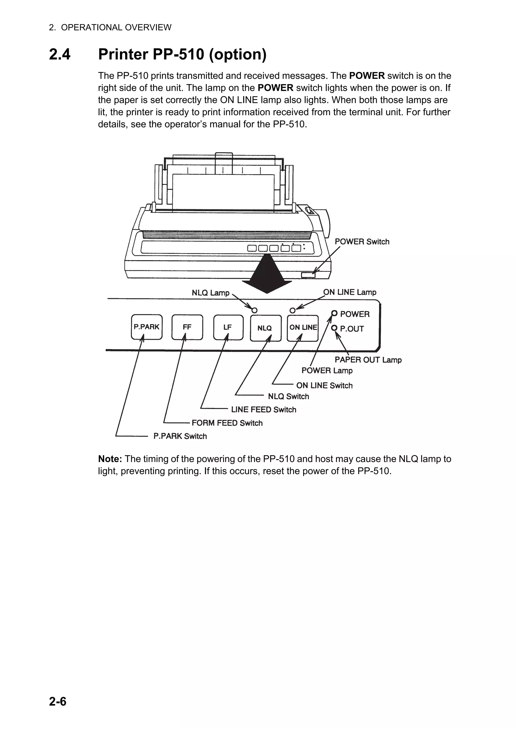
![2. OPERATIONAL OVERVIEW
2-7
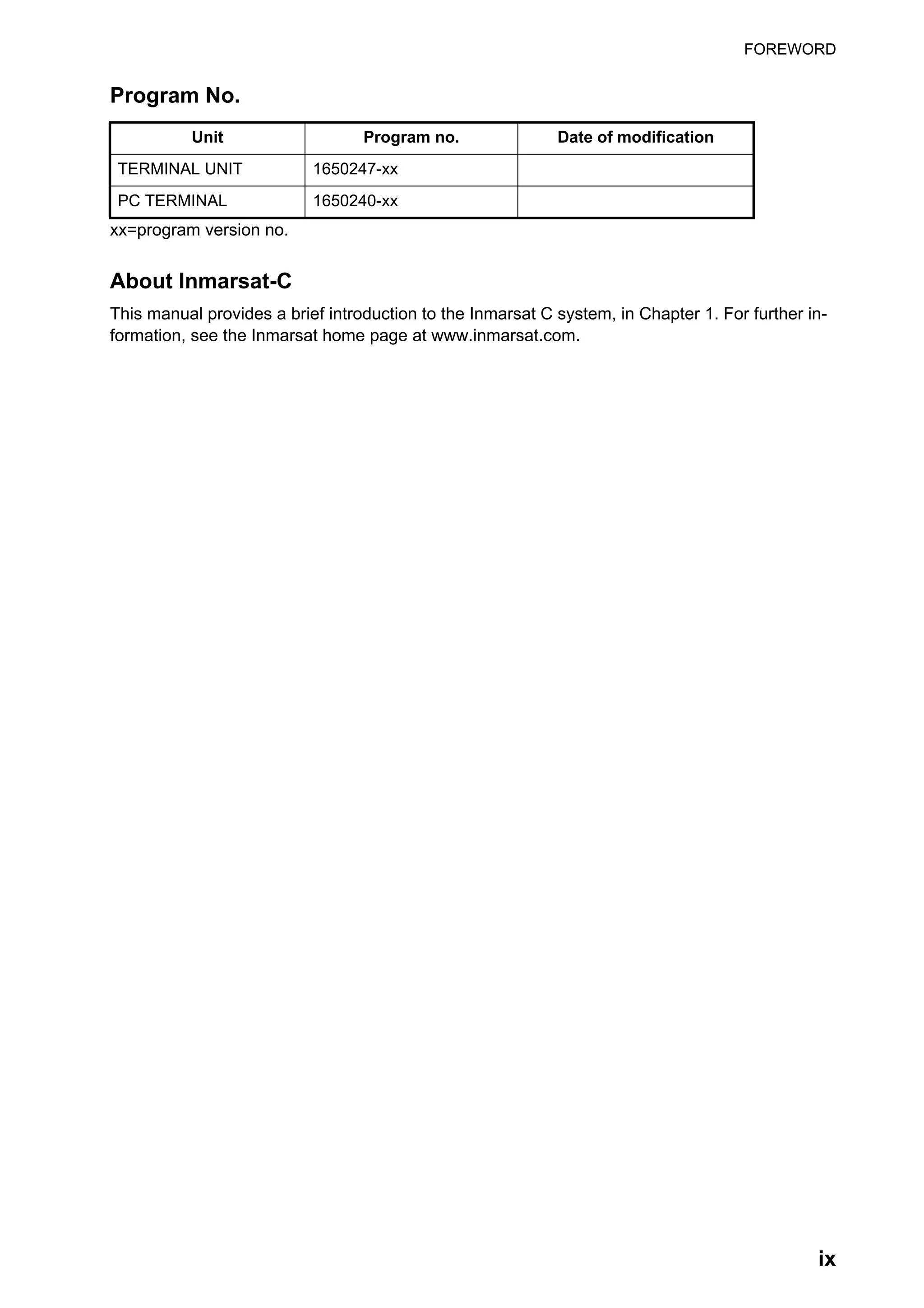
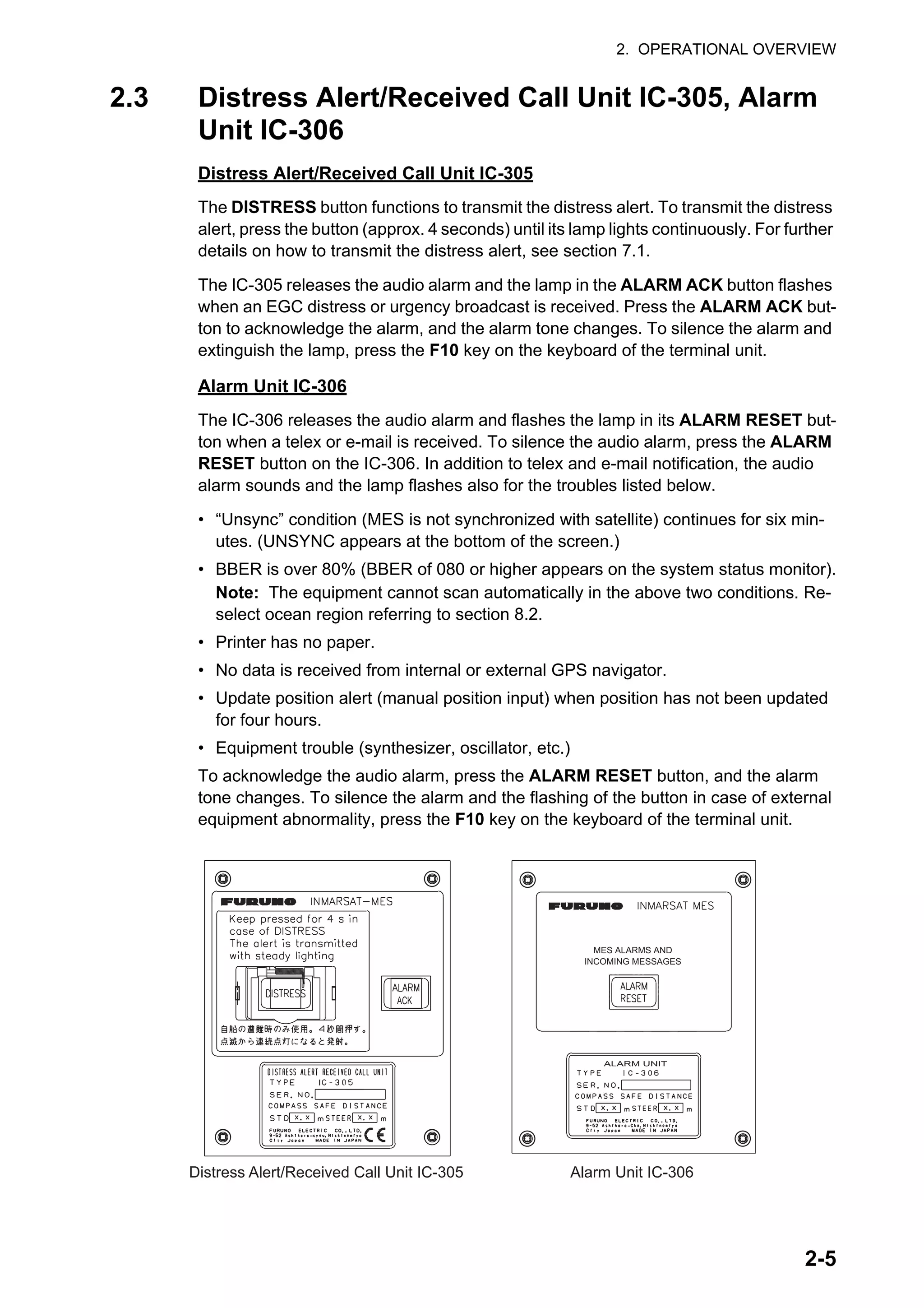
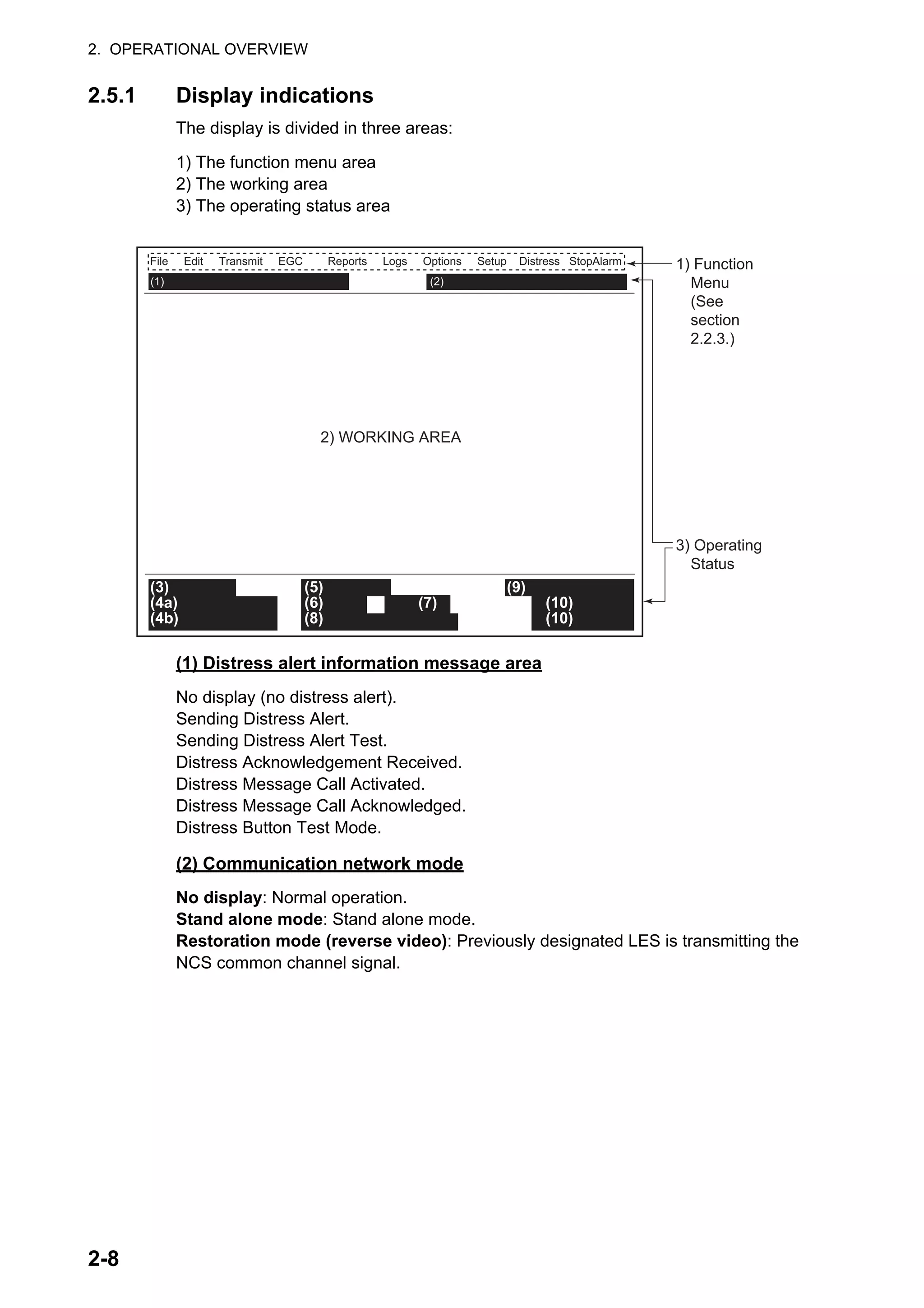
2.5 Standby Display
After the equipment is turned on and the diagnostic test is completed, the standby dis-
play appears, showing the results of the test. The system status monitor provides var-
ious operating information. For further information, see section 10.4.
After the diagnostic test is completed, the equipment automatically starts synchroniz-
ing itself with a satellite. When the indication "Retuning" is replaced with
"SYNC(NCS)", the synchronization process is completed. Then, you are ready to re-
ceive EGC messages. See section 3.4.
Note: When the caution "Pre-set LES ID for DISTRESS ALERT is invalid in the
present ocean region. Please input preferred LES ID in the [Distress Alert Setup]
menu." appears. Change the LES ID in the distress alert setup to match current ocean
region. See section 7.2.
File Edit Transmit EGC Reports Logs Options Setup Distress StopAlarm
Date
Time
Position
Waypoint
Course 345.5 DEG
Speed 10.2 kn
Current NCS
Current Channel
Current TDM
MES Status
GPS Status
DCE Memory
Jan-12-12
01:32 (UTC)
LAT 34:30.00N
LON 135:00.00E
LAT
LON
344 (IOR) LOGOUT
NCS CC
NCS CC
Idle
****
32818 Bytes free
IMN:
BBER
C/N
Send Level
Rx AGC Level
REF Offset Freq
Synthe Local
TCXO Control 131
Antenna Power Supply
Water Temperature
Water Current
Direction
Speed
Depth
443156710
000
OK ( 0 dB)
OK ( 0)
OK (254)
OK ( 0 Hz)
OK
OK(7.vX)
Current State: IDLE
DCE F18 Ver. xx
Retuning
NCS: IOR LOGOUT LAT: 34:30.00N
REC. MESSAGE EXISTS LON: 135:00.00E
Jan-12-12 01:32 (UTC)
68.2 DEG
232 DEG
1.9 kn
xx: Program Version No. of TERMCPU Board](https://image.slidesharecdn.com/felcom-18ome56740a2-220309163554/75/Felcom-18-ome56740-a_2-23-2048.jpg)
![2. OPERATIONAL OVERVIEW
2-11
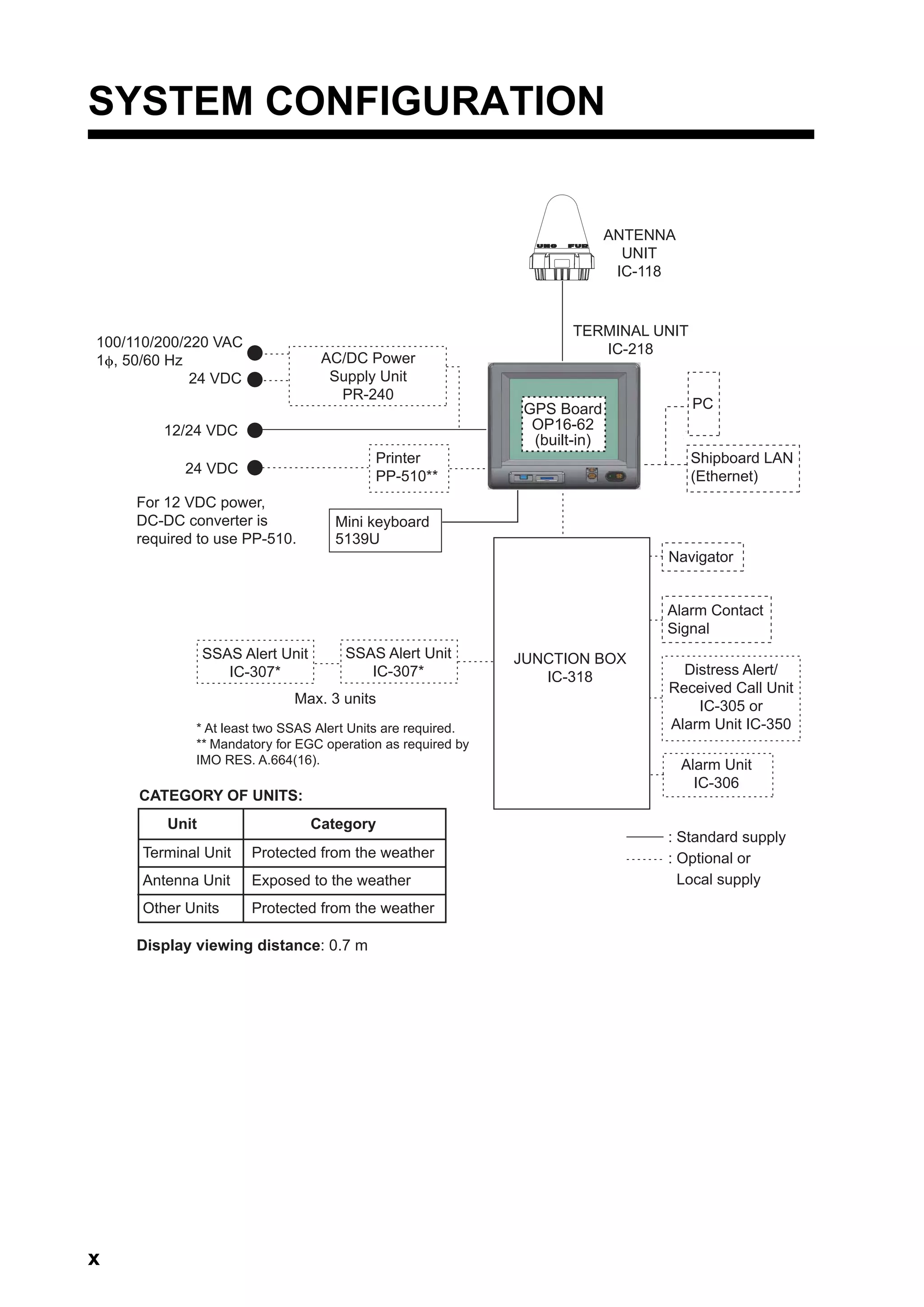
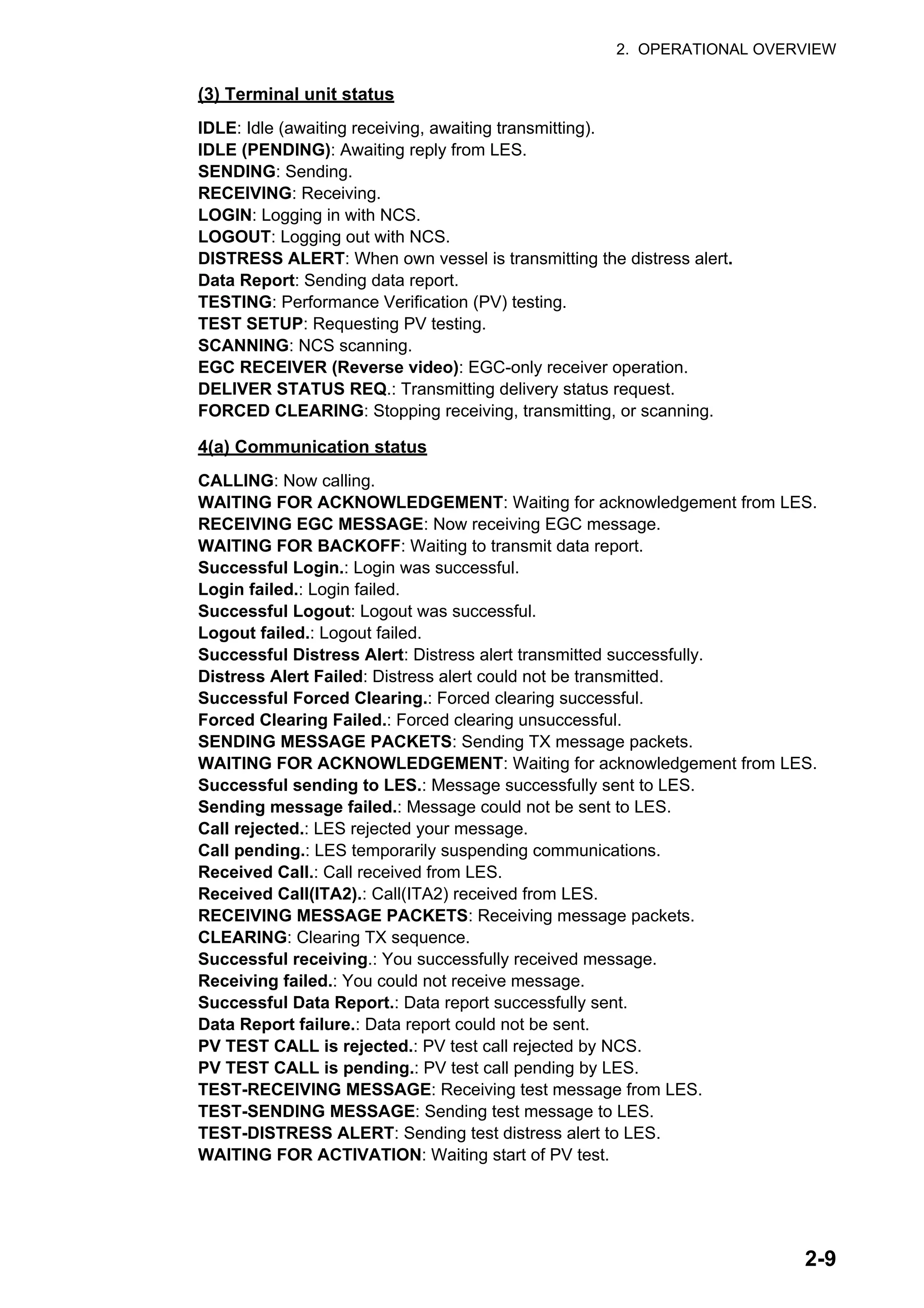
2.6 Menu Overview
Operation of the FELCOM is done through a menu system which you access with the
function keys (see section 2.2.3) at the top of the screen. The example below shows
how to select menu options from the [Editor Setup] menu.
1. Press the F8 key to display the [Setup] menu.
2. Select desired menu by pressing appropriate numeric key. For example, press the
2 key to show the [Editor Setup] menu. (You can also select a menu with the ↑
and ↓ keys. Press the Enter key after making a selection.)
3. Choose a desired menu item by pressing the ↑ or ↓ key followed by the
Enter key. A window displaying the options for the item selected or an
alphanumeric data entry window appears depending on your selection.
For example, the window at right shows the options for [Word Wrap].
4. Press the ↑ or ↓ key to select option desired and press the Enter key.
5. Long-press the Esc key to return to the standby display.
Note 1: On some menus the [Update] window appears after you press
the Esc key. This is done to ask you to confirm settings. [Yes] is select-
ed; press the Enter key to register settings, or press [→] to select [No]
and press the Enter key to escape. If invalid data is entered, an appli-
cable error message appears and the previous setting is restored.
Note 2: On the [System Setup] menu, the message "Wait..." appears (white charac-
ters on purple background) while a process is being done. The message disappears
once the process is completed.
Note 3: To return to the standby display at any time (except the message preparation
screen), long press the Esc key.
Setup
1. System Setup
2. Editor Setup
3. Terminal Setup
4. EGC Setup
5. Auto Mode Setup
6. E-Mail Setup
7. Directories
8. Configuration
2. System Setup
3. Editor Setup
4. Terminal Setup
5. EGC Setup
6. Auto Mode Setup
7. E-Mail Setup
8. Directories
9. Configuration
Editor Setup
Ascii
Insert
ON
ON
4 Char
69
Block
Full Screen
Text Mode
Edit Mode
Word Wrap
Line No.
Tab Width
Column Width
Cursor Type
Scroll
ON
OFF
Update
Yes No
Wait...](https://image.slidesharecdn.com/felcom-18ome56740a2-220309163554/75/Felcom-18-ome56740-a_2-27-2048.jpg)
![2. OPERATIONAL OVERVIEW
2-13
4. Click the [Next] button. Enter user name and organization. Click the applicable ra-
dio button at the bottom of the screen.
5. Click the [Next] button.
6. Click the [Next] button.
7. Click the [Install] button to start the installation. When the installation is completed,
the FELCOM dialog box appears.
8. Click the [Close] button at the top right corner of the dialog box. The [Setup Com-
plete] dialog box appears.
Note: If you want to launch the program now, click the box next to "Yes, launch
the program file." The application launches after the completion of step 9.](https://image.slidesharecdn.com/felcom-18ome56740a2-220309163554/75/Felcom-18-ome56740-a_2-29-2048.jpg)
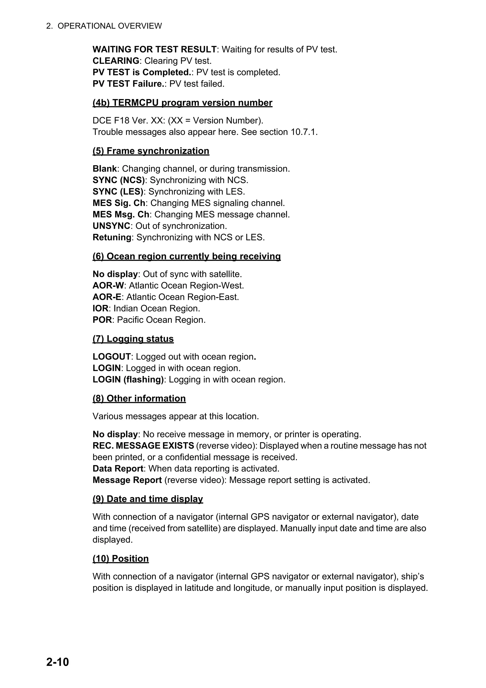
![2. OPERATIONAL OVERVIEW
2-14
9. Click the [Finish] button. The FELCOM application shortcut is created on the desk-
top of the PC.
2.8.2 How to start, quit the application
1. Turn on the terminal unit.
2. Turn on the PC.
3. Double-click the FELCOM icon to start the application.
4. To quit the application, press the F12 key while pressing the
Alt key. (You may also quit the application by clicking the
Close button.) Then, the window shown right appears.
5. Press the ← key to select [Yes] and then press the Enter key.
6. Turn off the PC according to the Windows operating procedure.
7. Turn off the terminal unit.
Note 1: If the application is quit using a method different from that described above
newly changed settings will not be memorized.
Note 2: The procedures described in this manual are intended for use with the termi-
nal unit. Operation from a PC is similar, however key names, etc. may be different and
some functions are not available. The functions not available with a PC are as follows:
Keying sequence Function not available with PC
F3-1 Distress priority selection on Transmit Message
F7-1
F7-2
F7-3
F7-4
F7-5
F7-6
F7-8
Position
Login
Logout
Abort (forced clearing)
Select NCS (selection of NCS common channel)
Ocean Region (selection of ocean region)
Functions other than [PV Test Result] and [Diagnostic Test] on [Test]
Menu
F8-1
F8-3
F8-4
Functions other than [IMN] on [System Setup] menu
[EGC Channel List] on [Configuration] menu
[NCS Channel List] on [Configuration] menu
OK to quit system?
Yes No](https://image.slidesharecdn.com/felcom-18ome56740a2-220309163554/75/Felcom-18-ome56740-a_2-30-2048.jpg)
![2. OPERATIONAL OVERVIEW
2-15
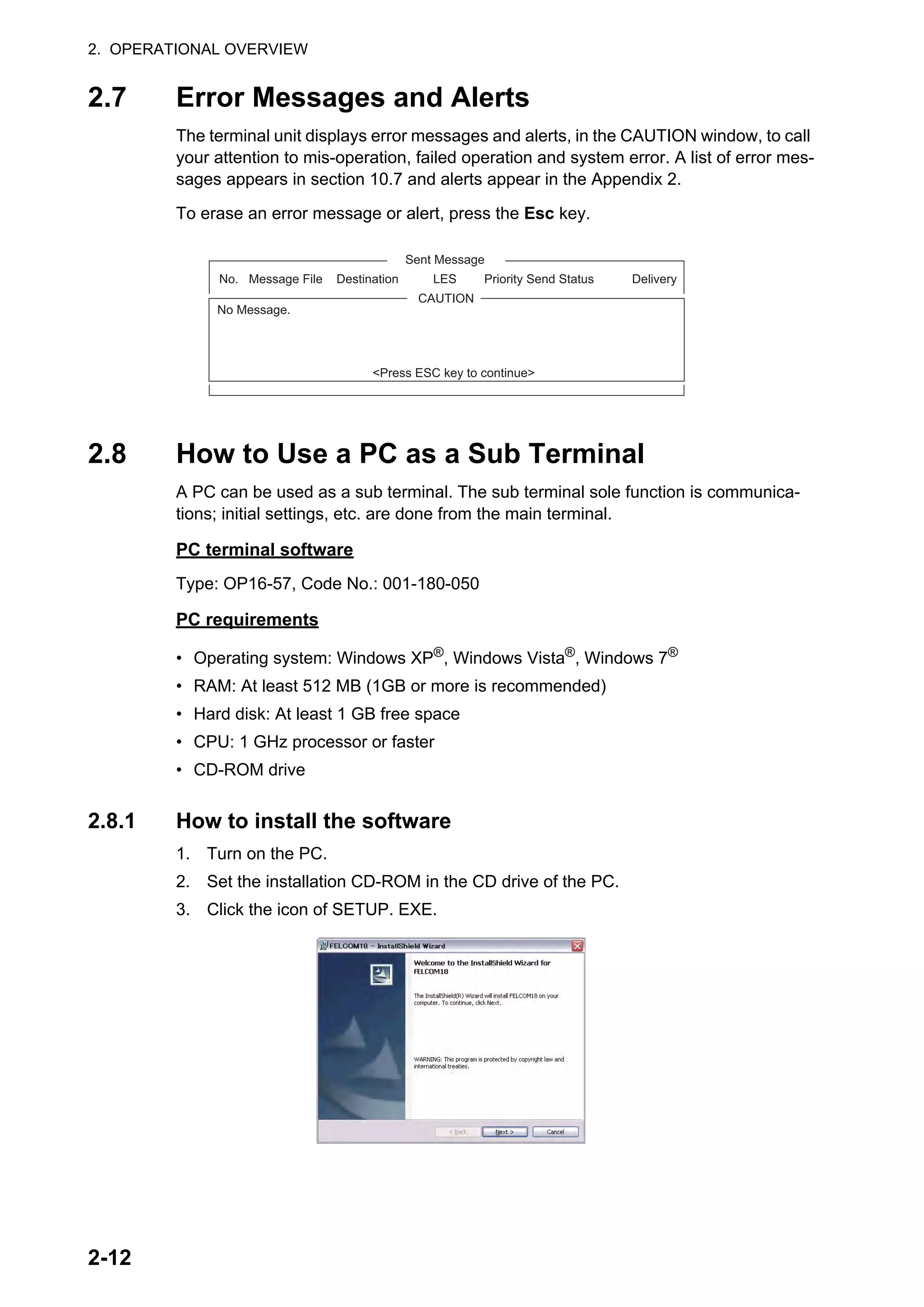
2.8.3 How to select the printer to use
1. Press the F1 key to open the [File] menu.
2. Press the 8 key to open the [Print Setting] window.
3. Select appropriate printer.
No Printer: Select if no printer is connected to the PC.
Windows Printer: Select if PC printer is connected to the
PC.
PP-510: Select if the PP-510 is connected to the PC.>
4. Press the Enter key to finish.
2.8.4 How to back up the system to PC or storage media
System data can be backed up to the selected folder on the PC’s hard drive or a stor-
age media (SD card).
1. If you are exporting settings to a storage media, insert the media in its drive.
2. Press the F8, 8 and 6 keys to show the [Export/Import] menu.
3. Select [Export] then press the Enter key.
4. Select the item to export then press the Enter key.
Sent Message: Export a maximum of 50 sent messages. The messages are
saved to the SD card under the original file name.
Received Message: Export a maximum of 50 received messages. The messages
are saved to the SD card under the original file name.
EGC Message: Export a maximum of 50 EGC messages. The messages are
saved to the SD card under the original file name.
Station List: Export the Station List.
LES List: Export the LES List.
E-Mail/SMS Service List: Export the [E-mail/SMS Service List].
Test: Export a maximum of five each of PV test and diagnostic test.
Maintenance: Export a maximum of 5000 entries of the [Current Position Log].
Settings: Export settings of SSAS, EGC, Network and Terminal Unit.
File
ALT-N
ALT-O
ALT-Q
ALT-S
ALT-D
ALT-P
1. New
2. Open
3. Close
4. Save
5. Delete
6. Rename
7. Print
8. Print Setting
9. MIME (Decode)
No Printer
Windows Printer
PP-510
Please select Printer
and press Enter key.
Print Setting
Export
1. Sent Message
2. Received Message
3. EGC Message
4. Station List
5. LES List
6. E-Mail/SMS Service List
7. Test
8. Maintenance
9. Settings](https://image.slidesharecdn.com/felcom-18ome56740a2-220309163554/75/Felcom-18-ome56740-a_2-31-2048.jpg)
![2. OPERATIONAL OVERVIEW
2-16
5. The [Browse for folder] dialog box appears. Select the destination where to export
the settings then click the [OK] button. The message "OK to Export?" appears.
6. Select [Yes] then press the Enter key.
7. Press the Esc key several times to return to the main menu.](https://image.slidesharecdn.com/felcom-18ome56740a2-220309163554/75/Felcom-18-ome56740-a_2-32-2048.jpg)
![3-1
3. SYSTEM INITIALIZATION
This chapter shows you how to initialize the FELCOM system. Once the equipment is
initialized, you need do no more than press a few keys to get fully automatic transmis-
sion and reception.
Inmarsat assigns an MES (your ship) an Inmarsat Mobile Number (IMN) when it ap-
plies for Inmarsat registration. The IMN is necessary to communicate in the Inmarsat
system and It is entered into the FELCOM system during the installation.
3.1 System Settings
3.1.1 Confirm the main terminal
The main terminal is where you set up the system. (You cannot set up the system from
an external terminal.) Confirm that the main terminal is selected as below.
1. Press the F8 key to show the [Setup] menu.
If your screen looks something like the one shown in the illustration above, you are
using the main terminal. (If you are using an external terminal, some menu items ap-
pear in gray.)
3.1.2 System setup
The [System Setup] menu is where you enter the date, time, operating mode, and port
function.
1. Press the F8 and 1 keys to show the [System Setup] menu.
2. [System Date & Time] is selected; press the Enter key to open the date entry win-
dow.
3. Enter the date with the numeric keys. (Entry of date is not necessary if a GPS nav-
igator is connected to the FELCOM.)
Setup
1. System Setup
2. Editor Setup
3. Terminal Setup
4. EGC Setup
5. Auto Mode Setup
6. E-Mail Setup
7. Directories
8. Configuration
System Setup
03:11 11-12-25 (YY-MM-DD)
123456789
INMARSAT-C
EXT
ON
INT
INT
System Date & Time
IMN
MES Operation Mode
Nav Port
LAN Port
Message Output Port
EGC Output Port
Network Setup
Command Window
Entered at installation
(Cannot be changed.)
For the serviceman](https://image.slidesharecdn.com/felcom-18ome56740a2-220309163554/75/Felcom-18-ome56740-a_2-33-2048.jpg)
![3. SYSTEM INITIALIZATION
3-2
4. Press the Enter key to close the window. (Note that the IMN is entered during in-
stallation. The IMN window cannot be opened.)
5. Select [MES Operation Mode] then press the Enter key to show the MES Opera-
tion window.
6. Select an operating mode, [INMARSAT-C] or [EGC]. The INMARSAT-C setting
provides telex communications and operates as an EGC receiver when the equip-
ment is not transmitting or receiving. The EGC setting enables EGC-only opera-
tion. In this case, "Current State: EGC RECEIVER" appears (reverse video) at the
bottom of the screen.
7. Press the Enter key to close the window.
8. Select [NAV Port] then press the Enter key.
9. Select the navigator connected to the FELCOM then press the Enter key.
OFF: No navigator connected.
Auto: If two or more navigators are connected, the FELCOM automatically selects
the position sensor in the order of GPS and Loran C.
INT: Use the navigator that is built into the terminal unit.
EXT: Use an external navigator.
Note: If the system is not fitted with the internal GPS receiver and there is no ex-
ternal GPS receiver, turn off the [NAV PORT] setting and enter position manually,
on the [Position] menu. See section 3.8
10. Select [LAN Port] then press the Enter key.
11. Select [ON] to enable LAN interface or [OFF] to disable it then press the Enter
key.
12. Select [Message Output Port] then press the Enter key.
13. Select the destination for sent messages then press the Enter key.
INT: Output messages to the main terminal.
LAN: Output messages to the LAN. ([LAN Port] set to [ON])
INT+LAN: Output messages to both the main terminal and the LAN. ([LAN Port]
set to [ON])
AUTO: All received messages are output according to the message sub address.
14. Select [EGC Output Port] then press then Enter key.
15. Select where to route received EGC messages then press the Enter key.
INT: Output EGC messages to the main terminal.
LAN: Output EGC messages to the LAN. ([LAN Port] set to [ON])
INT+LAN: Output EGC messages to both the main terminal and the LAN. ([LAN
Port] set to [ON])
16. Press the Esc key to open the [Update] window.
Note: [Network Setup] provides network initial settings. [Command Window] is no
use.
17. [Yes] is selected; press the Enter key to update the system settings.
18. Long-press the Esc key to return to the standby display.](https://image.slidesharecdn.com/felcom-18ome56740a2-220309163554/75/Felcom-18-ome56740-a_2-34-2048.jpg)
![3. SYSTEM INITIALIZATION
3-3
3.2 Terminal Setup
The [Terminal Setup] menu provides for selection of connection point, date display for-
mat, screen saver on/off and window colors.
1. Press the F8 and 3 keys to show the [Terminal Setup] menu.
2. For a 2nd DTE, do steps 1) - 2) below. Otherwise, skip to step 3.
1) Select [Connection] then press the Enter key to show the [Connect List]. The
[Connect List] shows the names of the FELCOM 18 terminals available for
communication.
Note: The No. Name, IMN, IP address/subnet mask and software version of
each terminal are shown. The asterisk marks the FELCOM 18 terminal cur-
rently selected for communication.
2) Select the FELCOM 18 terminal to connect then press the Enter key.
3. Select [Date Disp. Form] then press the Enter key to open its options window.
4. Select [YY-MM-DD], [MMM-DD-YY] or [DD-MMM-YY] as appropriate then press
the Enter key.
5. Select [Screen Saver] then press the Enter key.
6. Turn the screensaver ON or OFF as appropriate then press the Enter key. When
enabled, the screensaver automatically starts 10 minutes after there is no key op-
eration. To release the screensaver, press any key.
7. Select [Window Color] then press the Enter key. (The 2nd DTE does not have the
menu item [Brightness].)
Connection
Date Disp. Form YY-MM-DD
Screen Saver OFF
Window Color
Terminal Setup
Date Disp. Form YY-MM-DD
Screen Saver OFF
Window Color
Terminal Setup
IC-218 2nd DTE
No. Name IMN IP Address Software Version
*01 F18_123456 123432588 172.31.16.100/24 1650248-01
02 F18_133234 456789210 192.168.16.11/24 1650248-01
03
04
05
06
07
08
09
10
Connection List
Window Color Setup
Select Preset 1 2 3
Load Default
- - - - - - - - - - - - - - - - - - - - - - -
Edit Color
Window [ Base Window ]
Fore Color [ BLACK ]
Back Color [ WHITE ]
Brightness 0 1 2 3 4 5 6 7 8 9 10
- - - - - - - - - - - - - - - - - - - - - - -
To Change: ENTER To Change Value:L<=>R](https://image.slidesharecdn.com/felcom-18ome56740a2-220309163554/75/Felcom-18-ome56740-a_2-35-2048.jpg)
![3. SYSTEM INITIALIZATION
3-4
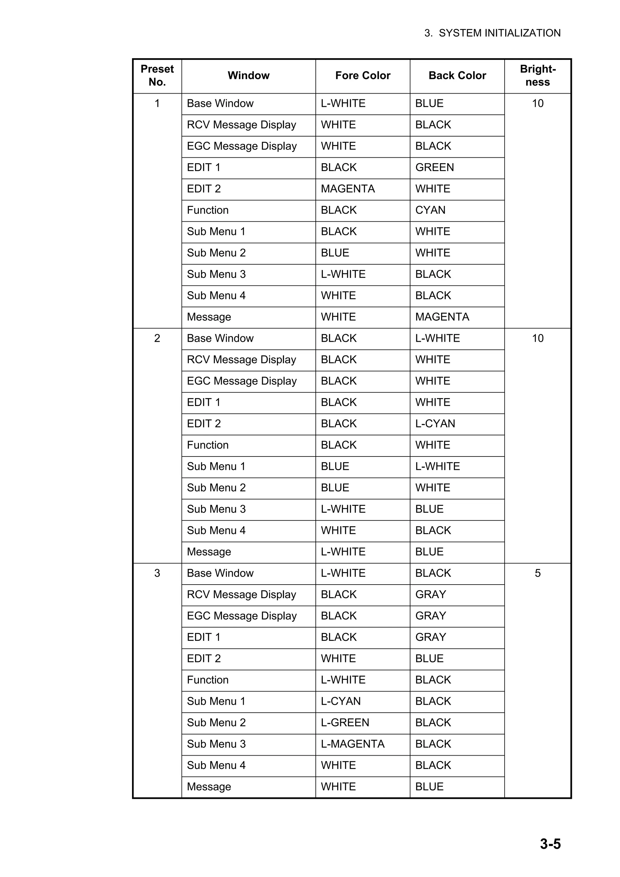
8. Set the window colors as follows:
1) [Select Preset] provides three preconfigured window color sets. Use one of
these sets, or continue this procedure to customize window colors. Preset 1
and 2 are daytime modes (bright environment), and Preset No.3 is for night-
time use (dark environment).
The brightness setting for each preset is as follows:
Preset 1: Brightness 10
Preset 2: Brightness 10
Preset 3: Brightness 5
2) Select [Window]. Use ← or → key to select the window for which to select col-
or.
Base Window: Standby display
RCV Message Display: Receive message display
EGC Message Display: EGC message display
EDIT1 - EDIT2: Editor screens 1 and 2
Function: Menu
Sub Menu 1 - Sub Menu 4: Sub menus 1-4
Message: Status message
3) Select [Fore Color].
4) Use ← or → key to select a color.
5) Select [Back Color].
6) Use ← or → key to select a color.
7) To select colors for other windows repeat steps 2)-6).
8) [Brightness] shows current brightness setting. For how to adjust brightness,
see section 2.1.2. See the table on the next page for the default settings for
each preset.
1:
2:
|
|
|
|
|
|
|
MENU
< [1] UNTITLED1 >
EDIT BASE WINDOW
CAUTION
MESSAGE
File Edit Transmit EGC Reports Logs Options Setup Distress StopAlarm](https://image.slidesharecdn.com/felcom-18ome56740a2-220309163554/75/Felcom-18-ome56740-a_2-36-2048.jpg)
![3. SYSTEM INITIALIZATION
3-6
9. Press the Enter key to show the [Update] window.
10. [Yes] is selected; press the Enter key.
11. Long-press the Esc key to return to the standby display.
To restore all default color settings, select [Window Color] from the [Terminal Setup]
menu, select [Load Default], press the Enter key then press the Enter key again.](https://image.slidesharecdn.com/felcom-18ome56740a2-220309163554/75/Felcom-18-ome56740-a_2-38-2048.jpg)
![3. SYSTEM INITIALIZATION
3-7
3.3 Login and Logout
Each time the terminal unit is turned on, login your vessel with the Inmarsat C system
to enable communications between your vessel and an LES. This is called login. Note
that you can transmit the distress alert or receive EGC messages even if you are not
logged in.If you will not be using the FELCOM for a prolonged period, you should lo-
gout from the Inmarsat C system, before turning off the terminal unit. The Inmarsat C
system will then register you as inactive, notifying anyone trying to call you that you
are currently unavailable. If you do not log out before turning off the power, some LESs
may attempt to send a message to you. They may charge your correspondent, even
if you don’t receive the message.
3.3.1 Login
1. Confirm that [SYNC (NCS)] appears at the bottom of the screen.
2. Press the F7 key to display the [Options] menu.
3. Press the 2 key to display the [Login] screen.
Note: The terminal unit must be “idle” to login. ("Current State: IDLE" appears at
the bottom of the screen.) When it is not idle, "Ignored: MES is not idle." appears.
Long-press the Esc key to return to the standby display. Wait until the terminal unit
becomes idle.
4. [Yes] is selected in the [Start] window; press the Enter key.
Options
1. Position
2. Login
3. Logout
4. Abort
5. Select NCS
6. Ocean Region
7. LES Information
8. Test
9. Maintenance
Login
Start
No
Yes
Yes](https://image.slidesharecdn.com/felcom-18ome56740a2-220309163554/75/Felcom-18-ome56740-a_2-39-2048.jpg)
![3. SYSTEM INITIALIZATION
3-8
5. Login begins, and the screen should look something like the one shown below.
When login is completed, the message "Successful Login." appears. Then, the
system goes into “Idle” status and [LOGIN] stops flashing.
6. Long-press the Esc key to return to the standby display.
3.3.2 Logout
1. Press the F7 and 3 keys to display the [Logout] screen.
2. [Yes] is selected in the [Start] window; press the Enter key. The message "Start-
ing Logout Process. Press any key to escape." appears.
3. When logout is completed, the message "Successful Logout." appears and the
[Current State] indication changes from [LOGOUT] to [IDLE]. Then, turn off the
FELCOM.
Current State: LOGIN
CALLING
DCE F18 Ver. **
02-02-25 02:02 (UTC)
LAT: 34:30.00N
LON: 135:30.00E
SYNC ( NCS )
NCS: IOR LOGIN
Options
Login
Starting Login Process.
Press any key to escape.
File Edit Transmit EGC Reports Logs Options Setup Distress StopAlarm
LOGIN replaces IDLE.
Flashing during login
Logout
Start
No
Yes
Yes](https://image.slidesharecdn.com/felcom-18ome56740a2-220309163554/75/Felcom-18-ome56740-a_2-40-2048.jpg)
![3. SYSTEM INITIALIZATION
3-10
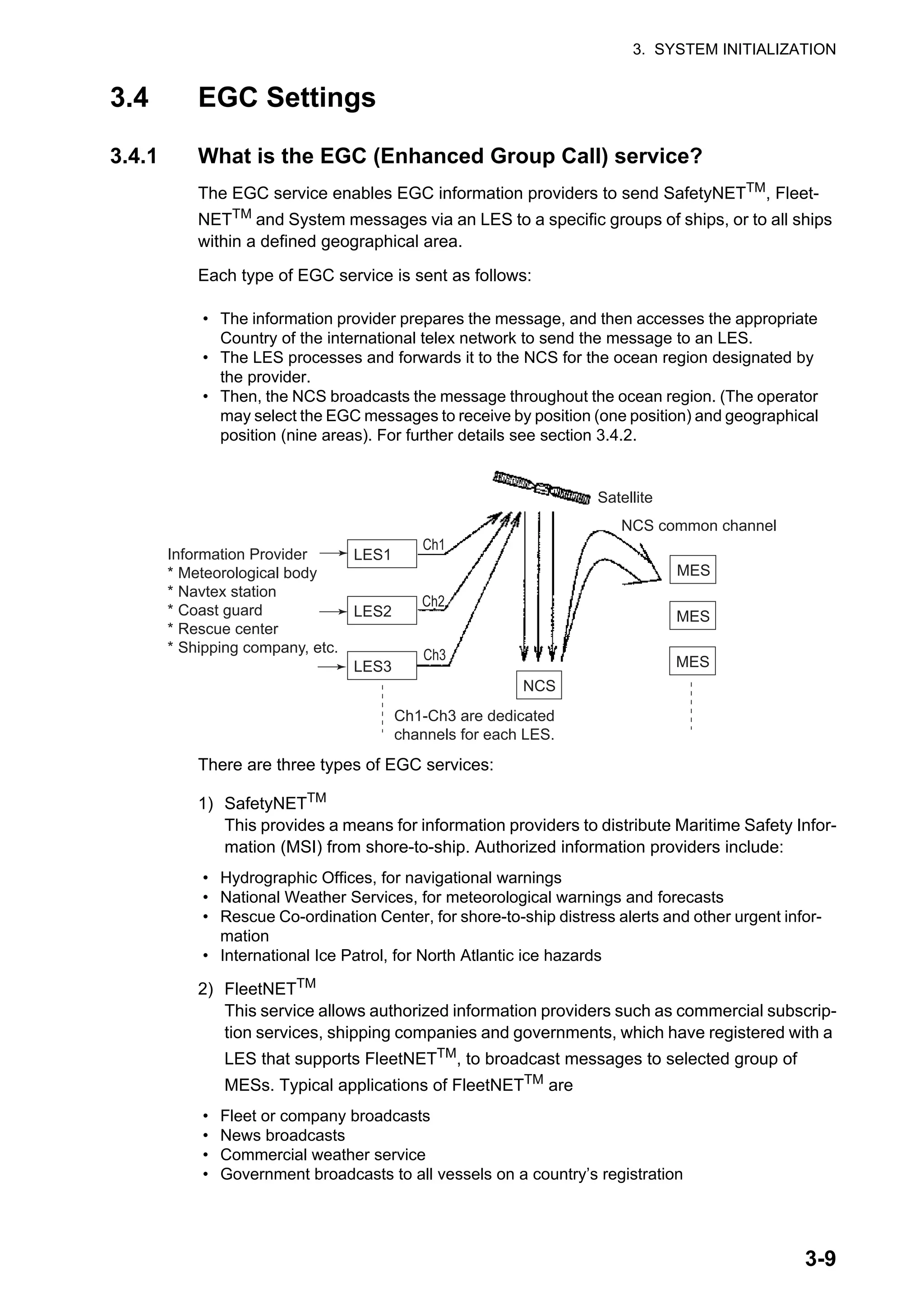
3) System: EGC system-related is sent by Inmarsat to certain ship groups and geo-
graphical areas.
3.4.2 EGC settings
The FELCOM receives EGC messages directed to its present position and Navarea
without further programming. The [EGC Setup] screen lets you select additional areas
for which to receive messages and also the Navtex station and type of message for
Coastal Warning (NAVTEX Re-broadcast).
1. Press the F8 and 4 keys to display the [EGC Setup] menu.
2. The cursor is selecting [Additional Position], where you can enter the L/L position
of an ocean region you want to receive broadcasts about. Press the Enter key to
open the additional position entry window.
3. Enter position as follows:
1) Enter latitude (xx°xxx).
2) Press the N or S key as appropriate to enter coordinate.
3) Enter longitude (xxx°xxx).
4) Press the E or W key as appropriate to enter coordinate.
4. Press the Enter key to close the window.
5. Select [Navarea(s)/Metarea(s)] and press the Enter key to open the nav area en-
try window.
EGC Setup
Ice reports
Meteo. forecasts
Pilot service
LORAN messages
OFF
OFF
OFF
OFF
SATNAV messages
Other navaid msg
QRU (no message)
OFF
OFF
OFF
: :
ON
Receive EGC Area
Additional Position - -:- - - - - -:- - -
Navarea(s)/Metarea(s)
Fixed Area - - - - - - - - - - - - - - - - - - - - - - - -
Waypoint (from NAV Equipment)
Coastal Warnings
Station Code
Type of Message (Can't reject other report)](https://image.slidesharecdn.com/felcom-18ome56740a2-220309163554/75/Felcom-18-ome56740-a_2-42-2048.jpg)
![3. SYSTEM INITIALIZATION
3-11
6. Enter additional Navarea(s) (I-XXI, max. of nine) in two digits, referring to the illus-
tration below for code number.
7. Press the Enter key to close the window.
Note: [Fixed Area] is where you enter fixed areas (max. 3) for chart correction ser-
vice. However, this service is not yet available; enter no data.
8. Select [Waypoint] then press the Enter key.
9. Choose [ON] to receive broadcasts for the area which contains the destination
waypoint set on the navigator. Press the Enter key to close the window.
10. Select [Station Code] then press the Enter key.
11. Enter the Navtex station code (A-Z) of the navarea, in upper case alphabet. For
details about Navtex stations, consult the operator’s manual of the Navtex receiv-
er. Press the Enter key to close the window.
12. Select the message type to receive: Use the arrow keys to select message type,
press the Enter key, select [ON] or [OFF] as appropriate then press the Enter key.
Note: The Navtex messages “Coastal navigational information,” “Meteorological
warning” and “Search and rescue alert” (they do not appear on the [EGC Setup]
menu) must always be received.
13. Press the Esc key to show the [Update] window.
14. [Yes] is selected; press the Enter key.
15. Long-press the Esc key to return to the standby display.](https://image.slidesharecdn.com/felcom-18ome56740a2-220309163554/75/Felcom-18-ome56740-a_2-43-2048.jpg)
![3. SYSTEM INITIALIZATION
3-12
3.4.3 How to add EGC channels
The EGC Channel List stores EGC channels. There are currently four EGC channels,
one for each satellite. These four channels are pre-programmed into the unit and
marked in the [EGC Channel List] with asterisks. When more EGC channels become
available you can add them to the list as below.
1. Press the F8, 8 and 3 keys to show the [EGC Channel List].
2. Use the arrow keys to put the cursor where there is no data entered. Current EGC
channels are marked with an asterisk. These channels cannot be changed.
3. Press the Enter key to open the EGC channel list entry screen.
4. Enter EGC channel frequency code then press the Enter key. The EGC channel
frequency code range is 6000-14000.
5. Press the Esc key to open the [Update] window.
6. [Yes] is selected; press the Enter key.
Note: If the EGC channel frequency code entered is invalid, the message "Input
Error: Channel No." appears. Clear the error message by pressing the Esc key.
Put the cursor at the invalid frequency, press the Enter key then enter correct fre-
quency code.
7. Long-press the Esc key to return to the standby display.
EGC Channel List
12580* 10840* 11088*
ENTER: Set ESC: Quit
11080*](https://image.slidesharecdn.com/felcom-18ome56740a2-220309163554/75/Felcom-18-ome56740-a_2-44-2048.jpg)
![3. SYSTEM INITIALIZATION
3-13
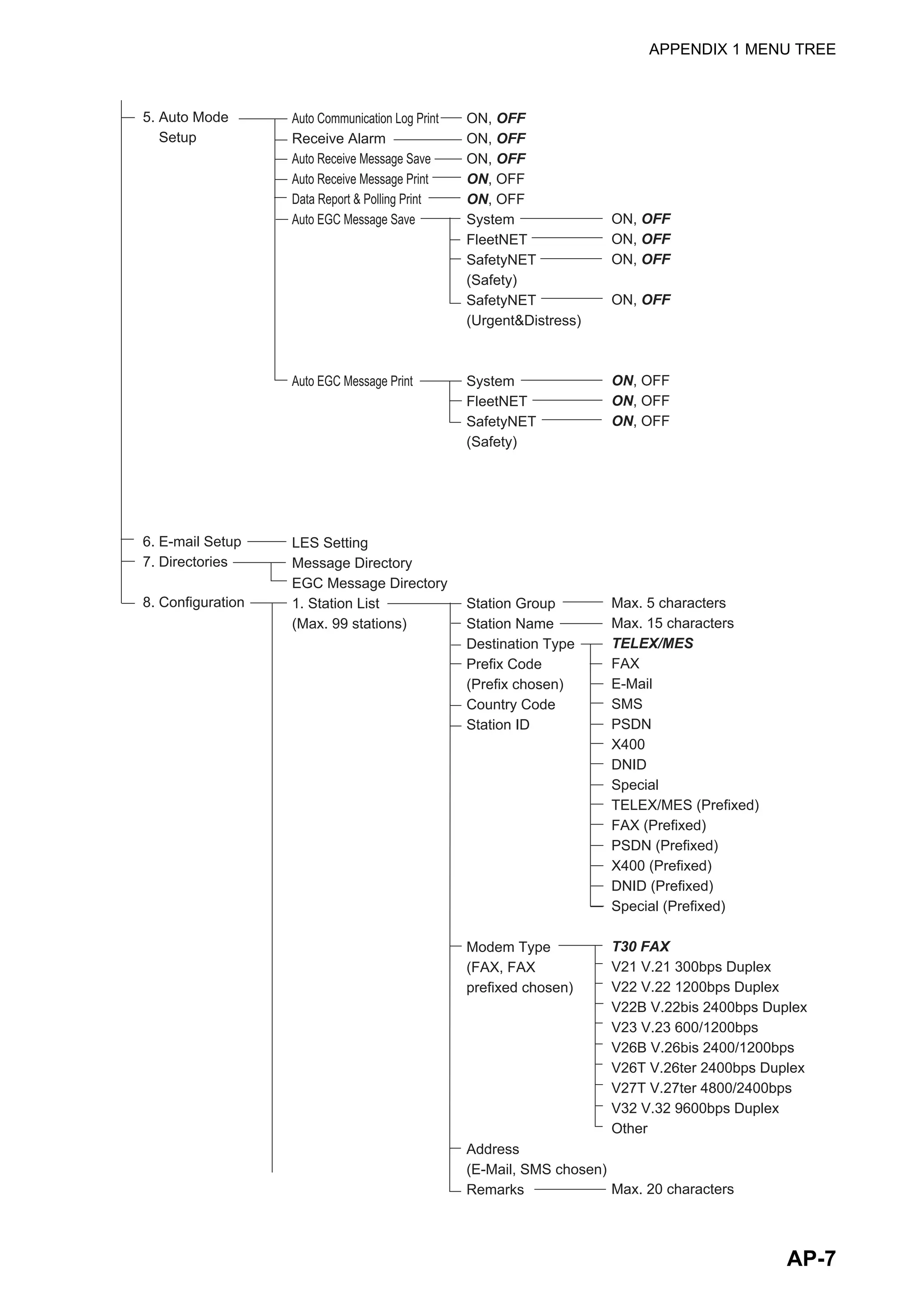
3.4.4 How to automatically save and print EGC messages
How to automatically save EGC messages
1. Press the F8 and 5 keys to display the [Auto Mode Setup] menu.
2. Select [Auto EGC Message Save] then press the Enter key.
3. Select the message to process then press the Enter key.
4. Select [ON] or [OFF] as appropriate then press the Enter key.
5. Long-press the Esc key to return to the standby display.
How to automatically print EGC messages
FleetNETTM
and SafetyNETTM
messages can be automatically printed.
1. Press the F8 and 5 keys to display the [Auto Mode Setup] menu.
2. Select [Auto EGC Message Print] then press the Enter key.
3. Select the message to process then press the Enter key.
4. Select [ON] or [OFF] as appropriate then press the Enter key.
5. Long-press the Esc key to return to the standby display.
Auto Communication Log Print OFF
Receive Alarm OFF
Auto Receive Message Save OFF
Auto Receive Message Print OFF
Data Report & Polling Print OFF
Auto EGC Message Save
Auto EGC Message Print
Auto Mode Setup
Auto EGC Message Save
System OFF
FleetNET OFF
SafetyNET (Safety) OFF
SafetyNET (Urgent & Distress) ON
Auto EGC Message Print
System OFF
FleetNET OFF
SafetyNET (Safety) OFF](https://image.slidesharecdn.com/felcom-18ome56740a2-220309163554/75/Felcom-18-ome56740-a_2-45-2048.jpg)
![3. SYSTEM INITIALIZATION
3-14
3.5 How to Add NCS Channels
This section shows you how to add NCS channels to the [NCS Channel List]. 19 chan-
nels can be listed per each ocean region. Currently, there are four NCS channels, and
they are marked with asterisks in the list. Add NCS channels to the list as below when
they become operational.
1. Press the F8, 8 and 4 keys to display the [NCS Channel List].
2. Use the arrow keys to put the cursor in a blank [ID] column.
3. Press the Enter key to open the data entry window.
4. Enter NCS channel ID number, in two digits (leading zero is not necessary). The
ID number range is 45-63.
5. Press the Enter key to close the window.
6. Press the → key to select the [FREQ] column then press the Enter key to open
the frequency input window.
7. Enter NCS channel frequency code. The frequency code range is 6000-14000.
8. Press the Enter key to close the window.
9. Press the Esc key to open the [Update] window.
10. [Yes] is selected; press the Enter key to register input.
Note: If the ID or frequency code entered is invalid the message "Input Error: NCS
ID" (for invalid ID) or "Input Error: Channel No." (for invalid frequency code) ap-
pears. Clear the error message by pressing the Esc key. Put the cursor at the in-
valid ID or frequency code. Then, press the Enter key and enter correct ID or
frequency code.
11. Long-press the Esc key to return to the standby display.
NCS Channel List
No AOR (WEST)
FREQ
11080*
01
02
03
04
05
06
07
08
ENTER: Set ESC: Quit
AOR (EAST)
FREQ
12580*
ID
144
1
1
1
1
1
1
1
POR
FREQ
12580*
ID
244
2
2
2
2
2
2
2
IOR
FREQ
10840*
ID
344
3
3
3
3
3
3
3
ID
044
0
0
0
0
0
0
0](https://image.slidesharecdn.com/felcom-18ome56740a2-220309163554/75/Felcom-18-ome56740-a_2-46-2048.jpg)
![3. SYSTEM INITIALIZATION
3-15
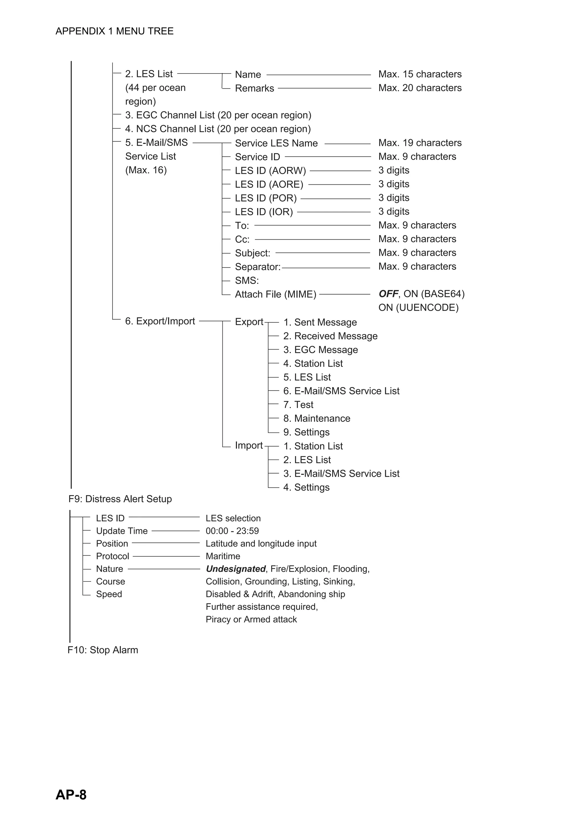
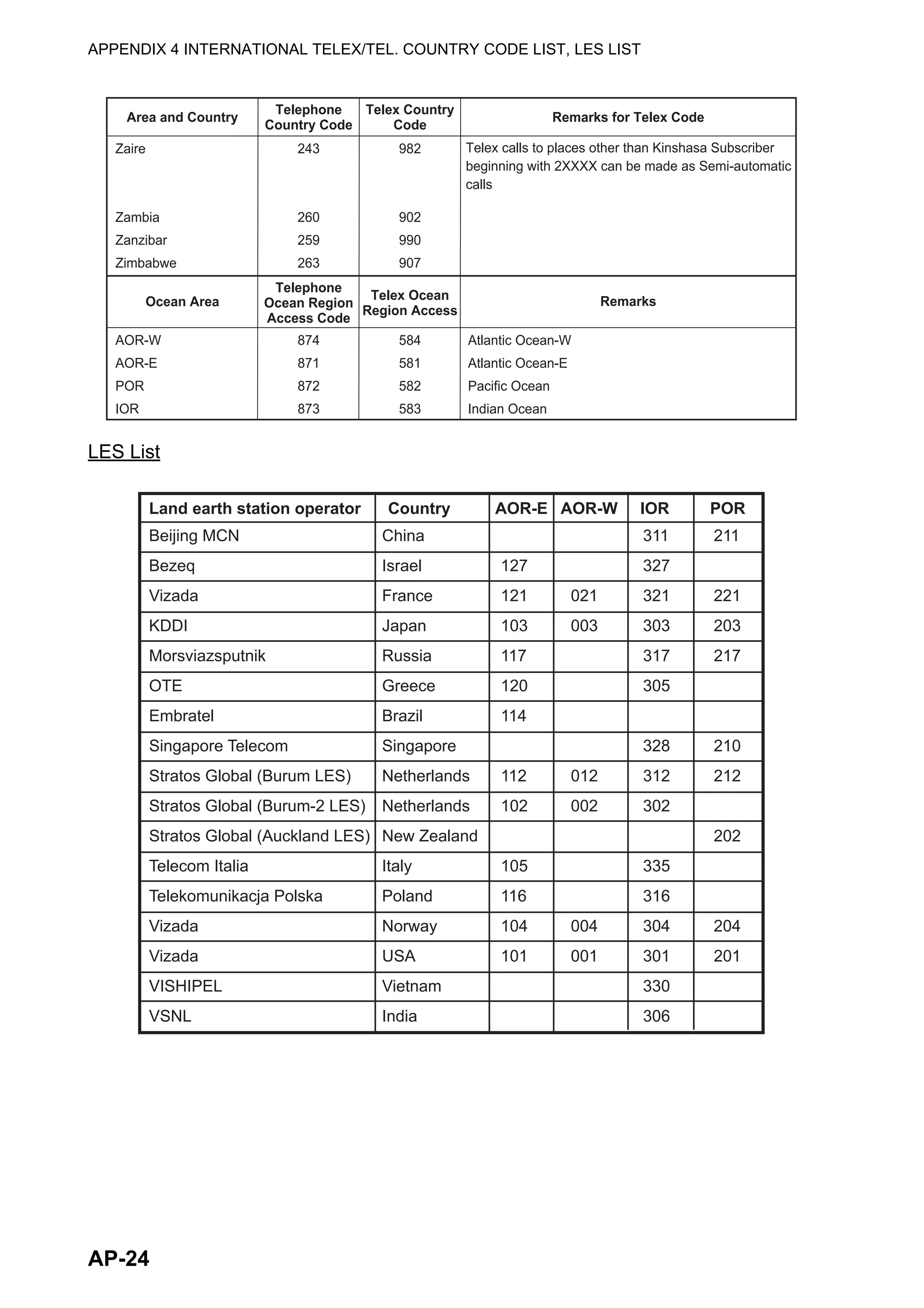
3.6 LES List
The LES List provides for storage of 44 LES names per ocean region.
3.6.1 How to register an LES to the LES list
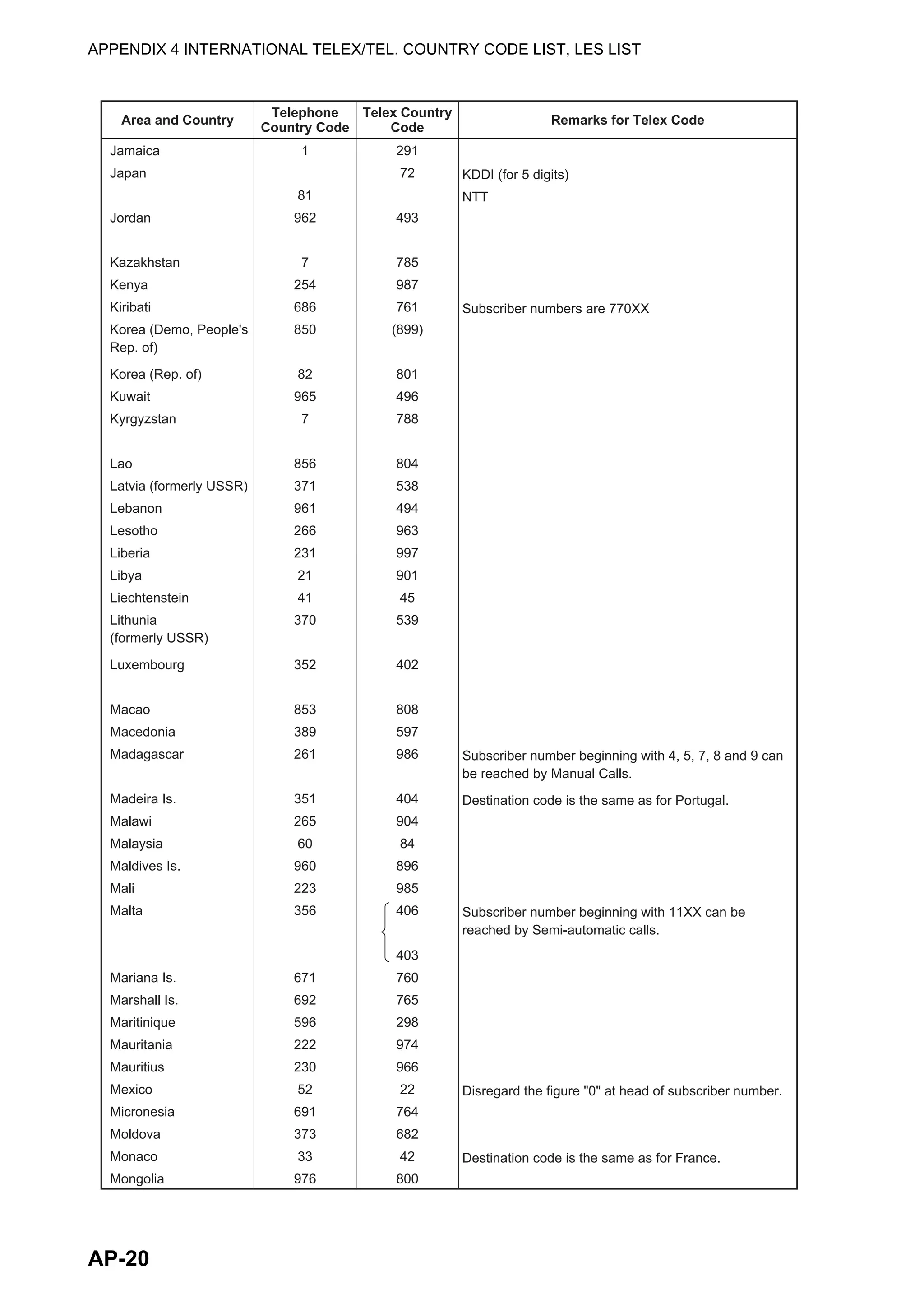
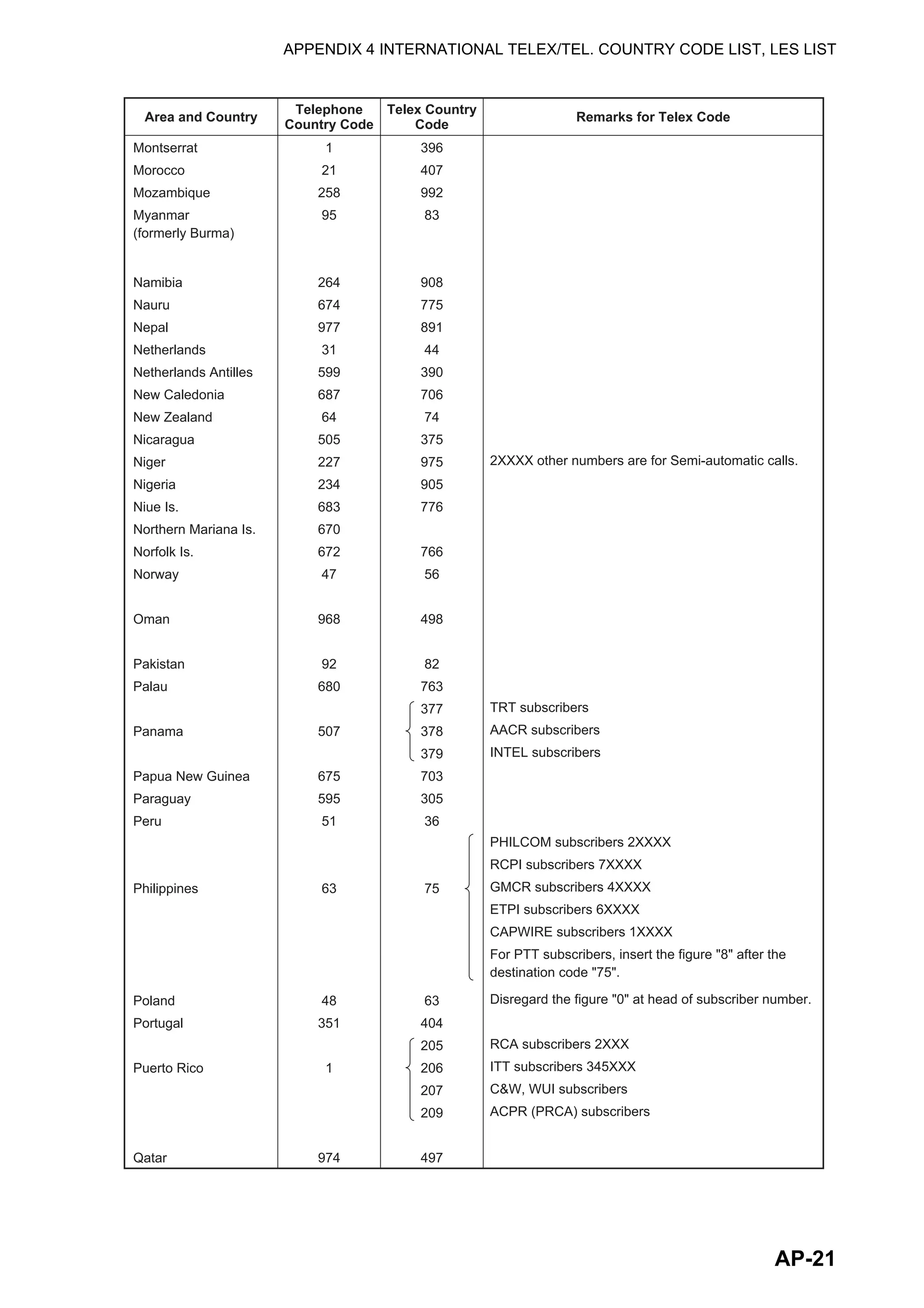
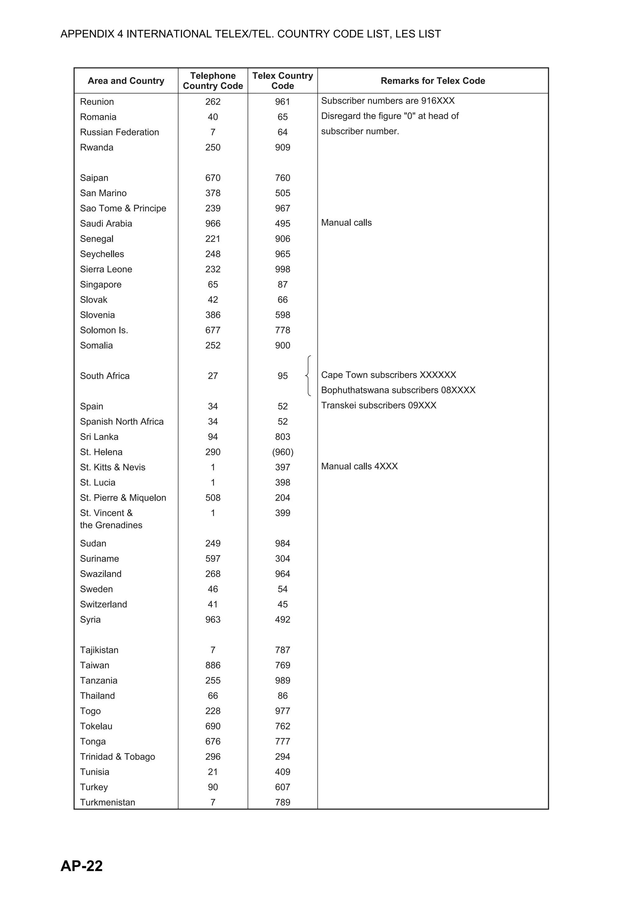
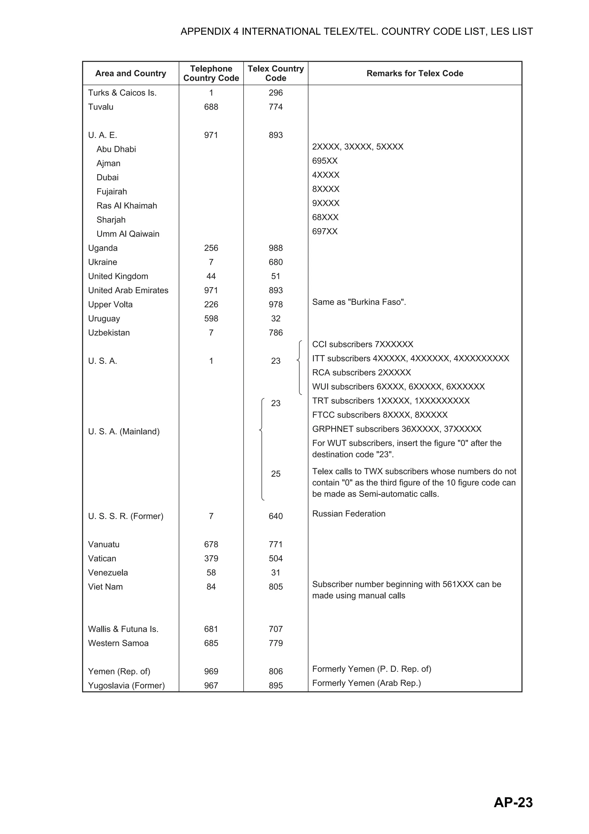
When a new LES is added, add it to the [LES List] as shown below. See the Appendix
4 for a list of LES.
1. Press the F8, 8 and 2 keys to display the [LES List].
2. Use the arrow keys to put the cursor where desired. For example, select 005 in
the AOR(WEST) column.
3. Press the Enter key.
4. [Name] is selected; press the Enter key to open the text entry window.
5. Enter LES name (maximum 15 characters) then press the Enter key.
6. Select [Remarks] then press the Enter key.
7. Enter remarks (max. 20 characters) then press the Enter key.
8. Press the Esc key to return to the [LES List].
9. Repeat steps 2-8 to enter another LES.
10. Long-press the Esc key to return to the standby display.
LES List
Ctrl+P: Print ENTER: List Entry ESC: Quit
AOR (WEST)
Name
Vizada 101
Stratos Global
KDDI
Vizada (NOR)
Telecom Italia
AOR (EAST)
Name
Vizada 201
Stratos Global
KDDI
Vizada (NOR)
POR
Name
Telenor S.S.Inc
Stratos Global
KDDI
Vizada (NOR)
OTE (Greece)
VSNL (India)
IOR
Name
No
00
01
02
03
04
05
06
07
Vizada 001
Stratos Global
KDDI
Vizada (NOR)
LES ID: XXX
0: AOR(WEST)
1: AOR(EAST)
2: POR
3: IOR
No. (00-43)
Put cursor here.
: KDDI
:
: JAPAN
Name
Remarks
Erase the Name to delete this LES.](https://image.slidesharecdn.com/felcom-18ome56740a2-220309163554/75/Felcom-18-ome56740-a_2-47-2048.jpg)
![3. SYSTEM INITIALIZATION
3-16
3.6.2 How to edit the LES list
1. Press the F8, 8 and 2 keys to display the [LES List].
2. Select the LES to edit then press the Enter key.
3. Do one of the following:
Change station name: Select [Name] then press the Enter key. Press the Back-
Space key to erase name, enter new name then press the Enter key.
Delete station name: Select [Name] then press the Enter key. Press the Back-
Space key to erase name then press the Enter key.
4. Press the Esc key to quit.
5. Long-press the Esc key to return to the standby display.
3.6.3 How to print the LES list
1. Press the F8, 8 and 2 keys to display the [LES List].
2. Press the P key while pressing the Ctrl key.
3. Long-press the Esc key to return to the standby display.
3.7 Station List
3.7.1 How to add stations to the station list
The FELCOM provides an address book for storing 99 station IDs. Enter station IDs
as shown below.
1. Press the F8, 8 and 1 keys to display the [Station List].
Note: You may sort the list by group name, station name or communication type
as follows:
Group name: Each press of Ctrl+G sorts the list by group name, in ascending or
descending order.
Station name: Each press of Ctrl+N sorts the list by station name, in ascending
or descending order.
Comm. type: Each press of Ctrl+T sorts the list by communication type, in as-
cending or descending order.
Station List
Ctrl+P: Print
Page Up, Page Down: Move
Sort (Ctrl+G: Group, Ctrl+N: Station Name, Ctrl+T: Type)
Group Station Name Type Code ID / Address
01
02
03
04
05
06
07
08
abc
xyz
Seagull
E-Mail
E-Mail
TELEX/
abc@ furuno.co.jp
xyz@ furuno.co.jp
584 463609999](https://image.slidesharecdn.com/felcom-18ome56740a2-220309163554/75/Felcom-18-ome56740-a_2-48-2048.jpg)
![3. SYSTEM INITIALIZATION
3-17
2. Press the ↓ key to put the cursor on a blank line then press the Enter key.
3. Press the Enter key to open the station group entry window.
4. Enter station group name (max. five characters) then press the Enter key.
5. Select [Station Name] then press the Enter key.
6. Enter station name then press the Enter key.
7. Select [Destination Type] then press the Enter key.
8. Select destination type desired then press the Enter key.
TELEX/MES: Telex communication/Mobile Earth Station (ship-to-ship Telex)
FAX: Facsimile service
E-Mail: E-mail (electronic mail) Service
SMS: Circuit Switched Data Network-not used.
PSDN: Packet Switched Data Network to an office computer via a data network
using X.25 standard.
X400: For future use
DNID: Data Network ID. Not used.
Special: Ship-to shore requests for safety service, accessed by using special 2-
digit codes
9. Follow appropriate procedure on the next several pages.
Procedure for telex
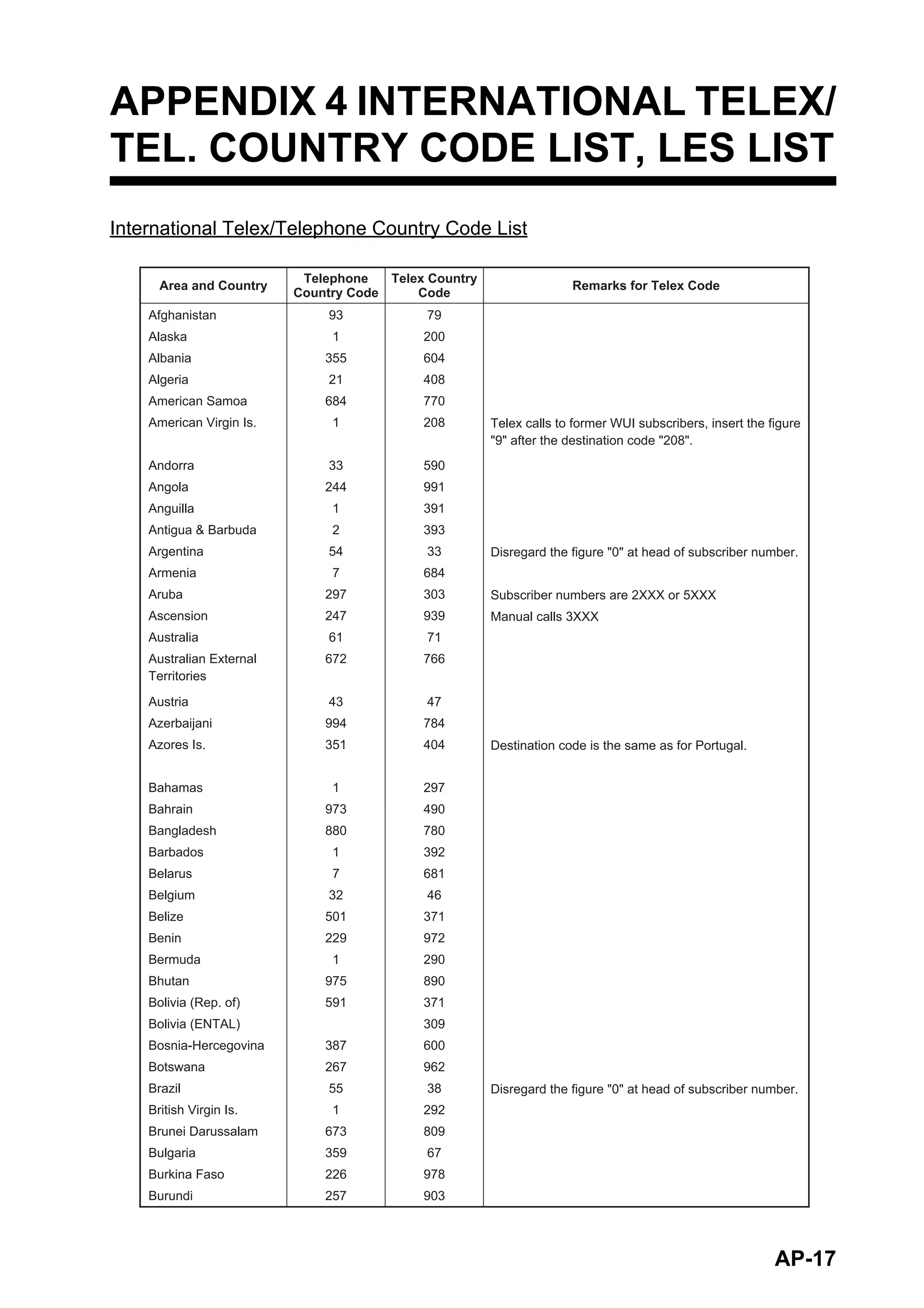
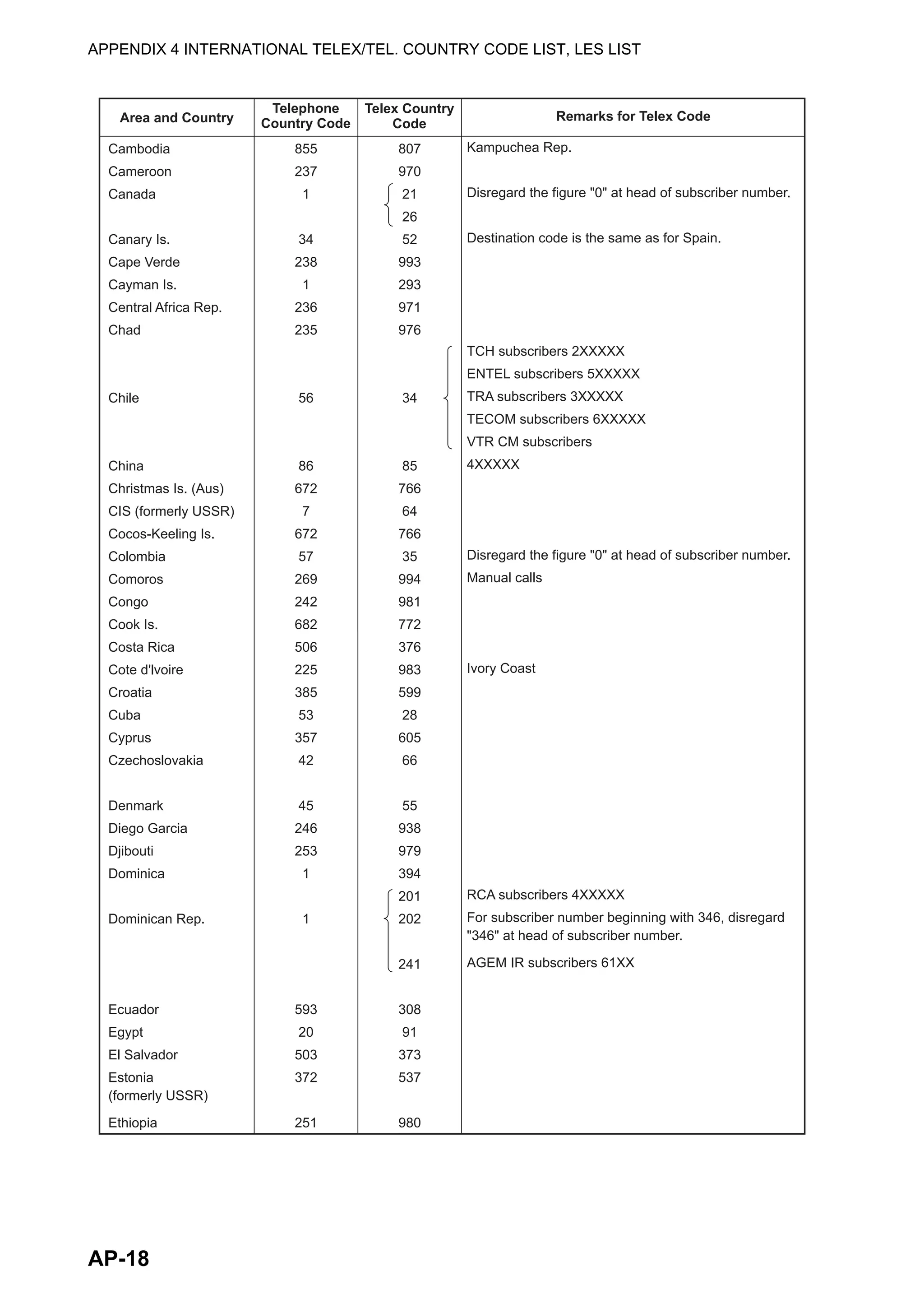
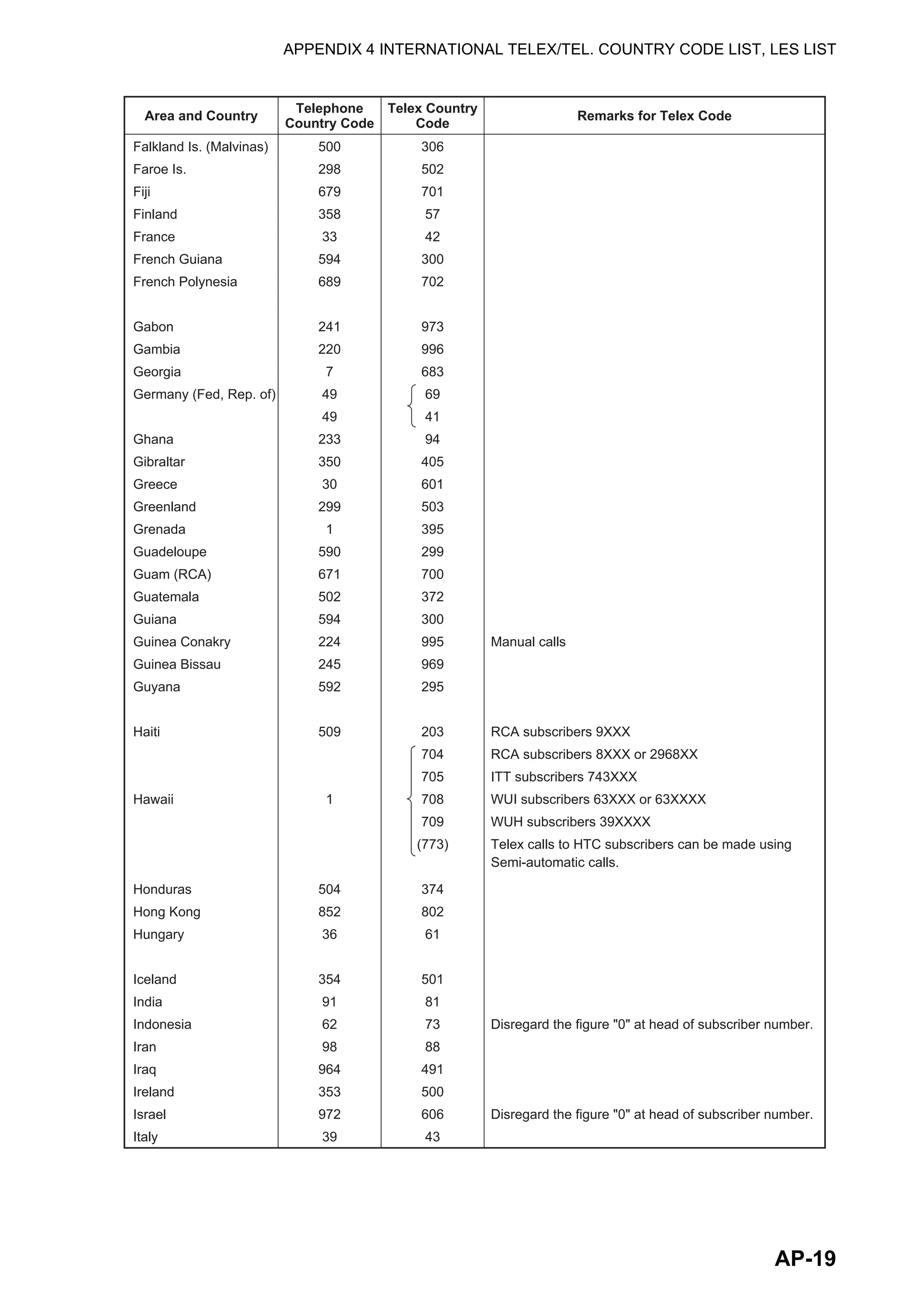
1. Select [Country Code] then press the Enter key.
2. For ship-to-shore telex, enter international telex country code; for ship-to-ship tel-
ex, enter ocean region. Press the Enter key. A list of international telex country
codes appears in the Appendix 4.
AOR-East: 581, POR: 582, IOR: 583, AOR-West: 584
3. Select [Station ID] then press the Enter key.
4. Enter telex subscriber number (for ship-to-shore) or MES Inmarsat Mobile Num-
ber (for ship-to-ship) then press the Enter key. A maximum of 15 characters can
be used, including space.
Station Group
Station Name
Destination Type TELEX/MES
Prefix Code
Country Code
Station ID
Modem Type
E-Mail Address
Remarks
Erase the Name to delete this station.
TELEX/MES
FAX
E-Mail
SMS
PSDN
X400
DNID
Special
TELEX/MES (Prefixed)
FAX (Prefixed)
PSDN (Prefixed)
X400 (Prefixed)
DNID (Prefixed)
Special (Prefixed)](https://image.slidesharecdn.com/felcom-18ome56740a2-220309163554/75/Felcom-18-ome56740-a_2-49-2048.jpg)
![3. SYSTEM INITIALIZATION
3-18
4. Enter telex subscriber number (for ship-to-shore) or MES Inmarsat Mobile Num-
ber (for ship-to-ship) then press the Enter key. A maximum of 15 characters can
be used, including space.
5. Select [Remarks] then press the Enter key.
6. Enter remarks then press the Enter key. A maximum of 20 characters can be
used.
7. Press the Enter key to close the window.
8. Long-press the Esc key to return to the standby display.
Procedure for Fax
1. Select [Country Code] then press the Enter key.
2. For ship-to-shore fax, enter international country code; for ship-to-ship fax, enter
ocean region. Press the Enter key. A list of international telex country codes ap-
pears in the Appendix 4.
3. Select [Station ID] then press the Enter key.
4. Enter the fax number then press the Enter key.
5. Select [Modem Type] then press the Enter key.
6. Select the modem type used by the subscriber then press the Enter key. For a
landline fax or a fax-equipped Inmarsat B MES, select [T30 FAX].
7. Select [Remarks] then press the Enter key.
8. Enter remarks then press the Enter key. A maximum of 20 characters can be
used.
9. Press the Esc key to return to the Station List.
10. Long-press the Esc key to return to the standby display.
Procedure for e-mail
1. Select [Address] then press the Enter key.
2. Enter the e-mail address of the recipient then press the Enter key.
3. Select [Remarks] then press the Enter key.
4. Enter remarks then press the Enter key. A maximum of 20 characters can be
used.
5. To enter another e-mail address, repeat the procedure from step 2 on page 3-17.
6. Long-press the Esc key to return to the standby display.
Modem Type
300bps Duplex
1200bps Duplex
2400bps Duplex
600/1200bps
2400/1200bps
2400bps Duplex
4800/2400bps
9600bps Duplex
T30
V21
V22
V22B
V23
V26B
V26T
V27T
V32
Other
FAX
V.21
V.22
V.22bis
V.23
V.26bis
V.26ter
V.27ter
V.32](https://image.slidesharecdn.com/felcom-18ome56740a2-220309163554/75/Felcom-18-ome56740-a_2-50-2048.jpg)
![3. SYSTEM INITIALIZATION
3-19
Procedure for SMS
1. Select [Address] then press the Enter key.
2. Enter the recipient’s mobile phone number, beginning with the country code then
press the Enter key.
3. Select [Remarks] then press the Enter key.
4. Enter remarks then press the Enter key. A max. of 20 characters can be used.
5. Press the Esc key to return to the station list.
6. To enter another SMS recipient, repeat the procedure from step 2 on page 3-17.
7. Long-press the Esc key to return to the standby display.
3.7.2 How to edit the station list
1. Press the F8, 8 and 1 keys to display the [Station List].
2. Select a station then press the Enter key.
3. Do one of the following:
Change station name: Select [Station Name] then press the Enter key. Press the
BackSpace key to erase name, enter new name then press the Enter key.
Delete station name: Select [Station Name] then press the Enter key. Press the
BackSpace key to erase name then press the Enter key.
4. Press the Esc key to save the changes.
5. Long-press the Esc key to return to the standby display.
3.7.3 How to print the station list
1. Press the F8, 8 and 1 keys to display the [Station List].
2. Press the P key while pressing the Ctrl key.
3. Long-press the Esc key to return to the standby display.
3.8 How to Enter Position
When there is no navigation data or the Nav Port
is disabled, enter ship’s position manually:
1. Press the F7 and 1 keys to display the [Ship
Position] menu.
2. Press the Enter key to open the latitude entry window.
3. Enter latitude (XX°XX.XX), press the N or S key as appropriate then press the En-
ter key.
4. Select [LON], press the Enter key, enter longitude (XXX°XX.XX), press the W or
E key as appropriate then press the Enter key.
5. Select [Update Time] then press the Enter key. Enter the current time then press
the Enter key.
6. Press the Esc key to open the [Update] window [Yes] is selected; press the Enter
key to update position and close the menu.
The position entered appears at the bottom right corner of the system status monitor
screen. It is also entered on [Update Distress Alert] screen (see Chapter 7).
34:30.00N
135:00.00E
LAT
LON
Update Time 09:40 11-11-12 (YY-MM-DD)
Ship Position](https://image.slidesharecdn.com/felcom-18ome56740a2-220309163554/75/Felcom-18-ome56740-a_2-51-2048.jpg)
![3. SYSTEM INITIALIZATION
3-20
3.9 How to Create a Directory
You can create and specify the directory where to save incoming and outgoing mes-
sages, to an SD card or the internal memory. The directory lets you save and organize
your messages conveniently.
3.9.1 How to create a directory for message storage
1. To make a directory in an SD card, insert an SD card in the SD card slot.
2. Press the F8 and 7 keys to open the [Directories] menu.
3. Select [Message Directory] then press the Enter key.
Note: The drive for an SD card is “C” and the drive for the internal memory is “A”.
To switch between the drives, select the <DRIVE> line then press the Enter key.
4. Press the Insert key to show the [Make Directory] window.
5. Enter directory name then press the Enter key.
Note 1: To create a directory within a directory (at step 5), repeat steps 4 and 5.
Note 2: To return to the root directory, place the cursor on [. .] then press the En-
ter key.
6. Press the ↑ key.
7. Press the Esc key to show the [Update] window.
8. [Yes] is selected; press the Enter key.
9. Long-press the Esc key to return to the standby display.
Received messages are saved to the directory created here.
To remove a directory, do steps 1-3 in the above procedure. Select the directory to
remove then press the Del key.
A directory for EGC message storage can also be made. Select [EGC Message Di-
rectory] at step 3.
Directories
Message Directory
EGC Message Directory
5. EGC Setup
6. Auto Mode Setup
7. E-Mail Setup
8. Directories
9. Configuration
Directories
Message Directory
EGC M<DIR><essag>456ABC <DIR>
e <DIDirectory
Message Directory
To View: SPACE Make Dir: INS Remove Dir: DEL
[C: ]
Filename Size Date & Time
<No Files>
0 Files exist 1456640 bytes free
Internal Memory <DRIVE>
123 <DIR> 2012-03-15 10:54
5. EGC Setup
6. Auto Mode Setup
7. E-Mail Setup
8. Directories
9. Configuration
Directories
Message Directory
EGC M<DIR><essa>456ABC <DIR>
e <DIDirectory
Message Directory
[C: ABC ]
Filename Size Date & Time
Root directory (Top of SD card hierarchy)
Internal Memory <DRIVE>
. <DIR> 2012-03-15 10:54
.. <DIR> 2012-03-14 11:44
Directory name](https://image.slidesharecdn.com/felcom-18ome56740a2-220309163554/75/Felcom-18-ome56740-a_2-52-2048.jpg)
![3. SYSTEM INITIALIZATION
3-21
3.9.2 How to specify the directory for message storage
1. Press the F8 and 7 keys to open the [Directories] menu.
2. Select [Message Directory] then press the Enter key. (If necessary, switch the
drive, C for SD card, A for the internal memory.)
3. Press the ↓ key to put the cursor on “..” then press the Enter key.
4. Select a directory then press the Enter key.
5. Press the ↑ key to put the cursor on the top line ([A: ]).
6. Press the Esc key to show the [Update] window.
7. [Yes] is selected; press the Enter key.
8. Long-press the Esc key to return to the standby display.
Note: The name of each message is automatically saved in the directory assigned,
and the file name is with the year, month and day (YYYY:MM:DD) the message was
received.
5. EGC Setup
6. Auto Mode Setup
7. E-Mail Setup
8. Directories
9. Configuration
Directories
Message Directory
EGC M<DIR><essa>456ABC <DIR>
e <DIDirectory
Message Directory
[C: ABC ]
Filename Size Date & Time
Root directory (Top of SD card hierarchy)
Internal Memory <DRIVE>
. <DIR> 2012-03-15 10:54
.. <DIR> 2012-03-14 11:44](https://image.slidesharecdn.com/felcom-18ome56740a2-220309163554/75/Felcom-18-ome56740-a_2-53-2048.jpg)
![3. SYSTEM INITIALIZATION
3-22
3.10 E-mail Service/SMS Station List
E-mail service providers and SMS stations are already registered in the FELCOM. To
add new e-mail service provider or SMS stations, follow the procedure below.
1. Press the F8, 8 and 5 keys to show the [E-Mail/SMS Service List].
2. Select a blank line in the [LES Name] column then press the Enter key.
3. Press the Enter key to open the [Service LES Name] entry window.
4. Enter the name of the LES that provides the e-mail service then press the Enter
key.
5. Select [Service ID (E-Mail)] then press the Enter key.
6. Enter the service ID then press the Enter key.
7. Select [Service ID (SMS)] then press the Enter key.
8. Enter the service ID then press the Enter key.
9. Select [LES ID (AORW)] then press the Enter key.
10. Enter the LES ID for AORW then press the Enter key.
11. Enter the LES IDs for AORE, POR and IOR.
12. Select [To:] then press the Enter key.
13. Type appropriate “To” header then press the Enter key.
14. Select [Cc:] then press the Enter key.
15. Type appropriate “Cc” then press the Enter key.
16. Select [Subject:] then press the Enter key.
17. Type appropriate “Subject” then press the Enter key.
E-Mail/SMS Service List
LES Name AOR.W AOR.E POR IOR
01
02
03
04
05
06
07
08
Telenor S.S.Inc
Stratos (NED)
Stratos Global
Vizada (NOR)
KDDI
Singapore T.
Vizada (France)
Stratos (AUS)
001 101 201 301
012 112 212 312
002 102 202 302
004 104 204 304
003 103 203 303
210 328
021 121 221 321
022 122 222 322
OFF
Service LES Name
Service ID (E-Mail)
(SMS)
LES ID (AORW)
(AORE)
(POR)
(IOR)
To:
Cc:
Subject:
Separator:
SMS:
Attach File (MIME)
Enter data for LES which offers e-mail services.
For details, contact LES directly.
Example: Enter data of the Vizada to do SMS mail
or e-mail service:
Service LES Name Vizada (NOR)
Service ID (e-mail) 28
Service ID (SMS) 66
LES ID (AORW) 004
AORE 104
POR 204
IOR 304
To: TO:
Cc: CC:
Subject: SUBJECT:
Separator: Blank
SMS: Blank
Attach FIle (MIME) ON(UUENCODE)](https://image.slidesharecdn.com/felcom-18ome56740a2-220309163554/75/Felcom-18-ome56740-a_2-54-2048.jpg)
![3. SYSTEM INITIALIZATION
3-23
18. Select [Separator:] then press the Enter key.
19. Type appropriate “Separator” (for example, blank space, STX, etc.) then press the
Enter key.
20. Select [SMS:] then press the Enter key.
21. If it is necessary to enter the special Prefix “sms+” before telephone number, type
it here. For example, for Singapore Telecom, enter sms+8190123456789.
22. Select [Attach File (MIME] then press the Enter key.
23. Select [ON(BASE64)], [ON(UUENCODE)] or [OFF] as appropriate then press the
Enter key. BASE64: General text converter, UUENCODE: UNIX text converter.
24. Long-press the Esc key to return to the standby display.
3.11 E-mail Settings
Choose the LES where to forward e-mail. Also, you may need to register with an LES
which provides e-mail services.
1. Press the F8, 6 and Enter keys to open the [E-Mail/SMS Service List].
2. Choose the LES where to send e-mail then press the Enter key.
3. Long-press the Esc key to return to the standby display.
E-Mail/SMS Service List
LES Name AOR.W AOR.E POR IOR
01
02
03
04
05
06
07
08
Telenor S.S.Inc
Stratos (NED)
Stratos Global
Vizada (NOR)
KDDI
Singapore T.
Vizada (France)
Stratos (AUS)
001 101 201 301
012 112 212 312
002 102 202 302
004 104 204 304
003 103 203 303
210 328
021 121 221 321
022 122 222 322](https://image.slidesharecdn.com/felcom-18ome56740a2-220309163554/75/Felcom-18-ome56740-a_2-55-2048.jpg)
![3. SYSTEM INITIALIZATION
3-24
3.12 How to Export, Import System Settings
You can export and import system settings to and from an SD card. This allows you
backup system settings and import them into the FELCOM in the event of a problem.
3.12.1 How to export system settings
1. Set a formatted SD card to the SD card slot.
2. Press the F8, 8 and 6 keys to show the [Export/Import] menu.
3. Select [Export] then press the Enter key.
4. Select the item to export then press the Enter key.
Sent Message: Export a maximum of 50 sent messages.
The messages are saved to the SD card under the origi-
nal file name.
Received Message: Export a maximum of 50 received
messages. The messages are saved to the SD card un-
der the original file name.
EGC Message: Export a maximum of 50 EGC messag-
es. The messages are saved to the SD card under the
original file name.
Station List: Export the [Station List].
LES List: Export the [LES List].
E-Mail/SMS Service List: Export the [E-mail/SMS Service List].
Test: Export a maximum of five each of PV test and diagnostic test.
Maintenance: Export a maximum of 5000 entries of the [Current Position Log].
Settings: Export the settings of SSAS, EGC, Network and Terminal Unit.
5. The message "OK to Export?" appears. [Yes] is selected; press the Enter key to
export selected data.
3.12.2 How to import system settings
1. Insert a SD card that contains system settings in the card slot.
2. Press the F8, 8 and 6 keys to show the [Export/Import] menu.
3. Select [Import] then press the Enter key.
4. Select the item to import then press the Enter key.
Station List: Import the [Station List].
LES List: Import the [LES List].
E-Mail/SMS Service List: Import the [E-mail/SMS Service List].
Settings: Import settings (SSAS, EGC, Network and Terminal Unit).
5. The message "OK to Import?" appears. [Yes] is selected; press the Enter key to
import selected data.
Export
1. Sent Message
2. Received Message
3. EGC Message
4. Station List
5. LES List
6. E-Mail/SMS Service List
7. Test
8. Maintenance
9. Settings
Import
1. Station List
2. LES List
3. E-Mail/SMS Service List
4. Settings](https://image.slidesharecdn.com/felcom-18ome56740a2-220309163554/75/Felcom-18-ome56740-a_2-56-2048.jpg)
![4-1
4. FILE OPERATIONS
This chapter describes how prepare, edit, save and print files (messages).
4.1 Files and Working Areas
To create a new message it is necessary to open a new file. After a new file is opened,
one of two working areas in the internal memory is secured to create the message.
The term “open a file” also refers to the loading of a prepared file into a working area.
When you remove a file from a working area this is called “closing a file.”
4.2 Preparing Files
There are two types of files: routine and confidential. Files can be assigned a file name
and saved to an SD card or the internal memory, for later use. The maximum message
size is 32 kilobytes.
4.2.1 How to prepare a routine file
1. Press the F1 key to open the [File] menu.
SD CARD MEMORY
INTERNAL MEMORY
FILE 1
FILE 2
FILE 3
FILE 4
INTERNAL MEMORY
1
2
Save Area
Save Area
TWO WORKING AREAS
Display
LCD
Can select one for display.
(Change Window on Edit menu)
[C: ] (Max. 2 GB)
[A: ] (Max. 2.4 GB)
File
1. New
2. Open
3. Close
4. Save
5. Delete
6. Rename
7. Print
8. Remove SD Card
9. MIME (Decode)
ALT-N
ALT-O
ALT-Q
ALT-S
ALT-D
ALT-P
0. Format SD](https://image.slidesharecdn.com/felcom-18ome56740a2-220309163554/75/Felcom-18-ome56740-a_2-57-2048.jpg)
![4. FILE OPERATIONS
4-2
2. Press the 1 key to select [New]. The display should now look something like the
illustration below.
Note: When two working areas are opened and you try to open a third file, the
message "Save this message" appears. When this occurs close an open file to
free a working area.
3. The cursor is on the first line. Type your message.
4. To transmit the message you have just prepared, go to section 5.1.2. To save it
to an SD card or the internal memory, for future transmission, go to section 4.3.2.
4.2.2 How to prepare a confidential file
If communicating with another FELCOM18, you can prepare a confidential message
by entering “S???-addressee code(-password):” in the first line of message text. You
can also receive confidential messages containing this header from a land subscriber
or any MES which uses the FELCOM18.
There are two types of confidential messages: message with addressee code and
message with both addressee code and password.
When the FELCOM receives a confidential message, the message is neither dis-
played nor printed immediately. To display or print the contents of a confidential mes-
sage, the recipient executes the procedure shown in section 5.2.3.
Addressee code and password
Caller and recipient agree beforehand on both the addressee code and the password.
The addressee code might be the title of the recipient; for example, CAPTAIN. The
password could be the classification of the message; for example, SECRET.
How to prepare a message with addressee code
Type the addressee code as shown in the illustration below and then type the text of
message.
<[1] UNTITLED1>
0001|
TELEX
----*---------+---------+---------+---------+---------+---------+---------<
1 Char. [ Line 1/ 1 Col. 1 ] [Insert ]
Cursor can be a square or an underline.
S???-addressee code: (text of message)
Be sure to enter colon.
maximum 8 characters](https://image.slidesharecdn.com/felcom-18ome56740a2-220309163554/75/Felcom-18-ome56740-a_2-58-2048.jpg)
![4. FILE OPERATIONS
4-3
How to prepare a message with both addressee code and password
Type the addressee code as shown in the illustration below and then type the text of
message.
The recipient enters the password to view the contents of the message.
4.2.3 Editor menu settings
The Editor menu sets the parameters of the text editor.
1. Press the F8 key to display the [Setup] menu then press the 2 key to show the
[Editor Setup] menu.
2. Set each item as required, referring to the descriptions below.
Text Mode: Select [Telex] to create a telex message. Only upper case alphabet
is permitted in telex. Use [Ascii] to create an e-mail message. Upper and lower
case alphabet may be used in an e-mail.
Edit Mode: Select [Insert] (insert character at cursor location) or [Overwrite] (write
over character at cursor location).
Word Wrap: Turn automatic hyphenation at the end of a line on or off
Line No.: Turn the line number display on or off. See the illustration below.
Tab Width: Set the horizontal tab width, two, four or eight tabs per line.
Column Width: Set 69 for telex, 40 to 80 for ASCII.
Cursor Type: Select the cursor configuration, block or underline.
Scroll: Sets how much the screen moves up over the page ([Full Screen] or [Half
Screen]) when the Page Up or Page Down key is operated.
S???-addressee code-password: (text of message)
Be sure to enter colon.
maximum 8 characters each
Editor Setup
Ascii
Insert
ON
ON
4 Char
69
Block
Full Screen
Text Mode
Edit Mode
Word Wrap
Line No.
Tab Width
Column Width
Cursor Type
Scroll
<[1] UNTITLED1>
0001|
Cursor can be a square or an underline.
Line Number
Displayed if Line No. is turned on in
Editor Setup menu.](https://image.slidesharecdn.com/felcom-18ome56740a2-220309163554/75/Felcom-18-ome56740-a_2-59-2048.jpg)
![4. FILE OPERATIONS
4-4
4.2.4 Text operations
How to cut and paste text
1. Use the arrow keys to place the cursor on the first character of the text to cut.
2. Highlight the text to be cut by pressing the → key while pressing and holding the
Shift key. You can use the ← or → key to adjust the highlight. The figure below
shows the appearance of highlighted text.
3. Press the F2 key to open the [Edit] menu.
4. Press the 1 key to select [Cut]. The highlighted text is cut
and the remaining text is reformatted. If you make a mis-
take, you can immediately restore the text by pressing
the Insert key.
5. To move the text to a new location after it has been cut,
place the cursor at the exact spot in the message where
the cut text is to start. When the text cursor is placed cor-
rectly, press the F2 key and then the 3 (Paste) key.
How to copy and paste text
1. Select the text to copy.
2. Press the F2 key to open the [Edit] menu.
3. Press the 2 key to select [Copy]. The selected text is copied to the clipboard.
4. Place the cursor at the exact spot on the message where the copied text is to start.
5. Press the F2 key followed by the 3 key. The text is inserted at the cursor location.
Insert (with Citation)
When you reply to a received message, you can insert “>” in a received message at
the head of the received message to distinguish it from your message.
1. Press the F2 key to open the [Edit] menu.
2. Press the 4 key.
3. Select the file to use. (Use the Spacebar to view content of file. Press the Esc to
close the file.)
4. Press the Enter key.
Select All
Select the entire current file for cut and copy:
1. Press the F2 key to open the [Edit] menu.
2. Press the 5 key.
<[1] UNTITLED1>
Highlight
0001 WE ARE CONFIDENT THAT YOU WILL ENJOY MANY YEARS OF OPERATION WITH
0002 THIS INMARSAT STATION CONGRATULATIONS ON YOUR CHOICE
0003 CONGRATULATIONS ON YOUR CHOICE OF FURUNO FELCOM
Edit
1. Cut
2. Copy
3. Paste
4. Insert (With Citation)
5. Select All
6. Search or Replace
7. Goto Line
8. Time or Pos. Ins
9. Change Window
DEL
ALT-C
INS
ALT-A
ALT-V](https://image.slidesharecdn.com/felcom-18ome56740a2-220309163554/75/Felcom-18-ome56740-a_2-60-2048.jpg)
![4. FILE OPERATIONS
4-5
Search and replace
How to search text
1. At the [Edit] menu, press the 6 key to select [Search or
Replace].
2. Press the 1 key to select [1. Search].
3. [Search Word] is selected; press the Enter key to show
the search word entry window.
4. Type the word to search then press the Enter key.
5. Select [Direction] then press the Enter key.
6. Select [Forward] or [Back] to select the direction to search from the cursor location
then press the Enter key.
7. Press the Esc key to show the [Search Start] confirmation window.
8. [Yes] is selected; press the Enter key to start the search.
When the unit finds the word, the cursor stops at the first character of the word. If
the string could not be found, the message "Not Found (To Quit: ESC)" appears.
Press the Esc key to quit.
9. To continue the search, press the Enter key.
How to replace text
1. At the [Edit] menu, press the 6 key to select [Search or Replace].
2. Press the 2 key to select [2. Replace].
3. [Search Word] is selected; press the Enter key to show
the search word entry window.
4. Type the word to search then press the Enter key.
5. Select [Replace Word] then press the Enter key.
6. Enter the replace word then press the Enter key.
7. Select [Direction] then press the Enter key.
8. Select the direction (forward or back) to search from the cursor location press the
Enter key.
9. Select [Query or ALL] then press the Enter key.
10. Select [Query] or [ALL].
Query: Stop at each occurrence of word to answer yes or no to replacement.
ALL: Replace every occurrence of word without stopping to confirm.
11. Press the Esc key to show the [Replace Start] confirmation window.
12. [Yes] is selected; press the Enter key to start the replacement.
If you selected [ALL] at step 10, all occurrences of the search word are replaced
with the replace word. If the string could not be found, the message "Not Found
(To quit: ESC)" appears. Press the Esc key to quit.
If you selected [Query] at step 10, the message "Replace OK? (OK: ENTER Pass:
SPACE To quit: ESC)" appears when the search word is found. Press the Enter
key to replace the word, or hit the Spacebar to go to the next occurrence of the
search word.
1. Search Alt-F
2. Replace Alt-R
Search or Replace
Search Word
Direction Forward
Search
Search Word
Replace Word
Direction Forward
Query or ALL Query
Replace](https://image.slidesharecdn.com/felcom-18ome56740a2-220309163554/75/Felcom-18-ome56740-a_2-61-2048.jpg)
![4. FILE OPERATIONS
4-6
Go to line
Move the cursor to the desired line in the current file.
• Top of text: Go to top of text
• End of text: Go to end of text
• Go to line: Specify line number to go to.
Press the F2 and 7 keys. Place the cursor where desired then press the Enter key.
Time or Pos. Ins
Insert time or position in a sentence
1. At the [Edit] menu, press the 8 key to select [Time or Pos.
Ins.]
2. Put the cursor where to insert the information then press the 1 key to insert time
or the 2 key to insert position.
4.3 How to Save Files
4.3.1 How to handle SD cards (including SDHC cards)
After you have created a message you may wish to save it to an SD/
SDHC card or the internal memory), for future use. (The internal mem-
ory stores up 2.4GB of TX files.)
Cards 2GB or less do not require formatting. Cards above that capacity must be for-
matted (on the Terminal Unit), and their capacity after formatting is 2GB. (A PC will
also read them as being 2GB.) The following cards have been tested with the Terminal
Unit:
How to insert an SD card: Gently insert an SD card into its slot on the front panel of
the terminal unit, connector side down and front. Handle the cards carefully to prevent
damage, which could cause loss of data.
How to format an SD card: Insert the SD card into its slot. Press the F1 and 0 keys.
[Yes] is selected; press the Enter key to format the card.
How to eject an SD card: Press the F1 and 8 keys. [Yes] is selected; press the Enter
key then push the card to release it from the slot.
How to handle SD cards
• Do not remove a card from the slot until a card-related operation is completed, to
prevent loss of data and damage to the card.
• You can prevent writing to the card. On the side that does
not have the cutoff corner, there should be a white switch.
Move the switch down to engage write protect.
• Panasonic RP-SDP 4, 8, 16, 32GB
• TOSHIBA SD-E 4, 8, 16, 32GB
• HAGIWARA HPC-SD/SDH 2,4GB
• BUFFALO RSDC-S 2, 8GB
• I-O DATA SD/SDH-V 2,16GB
• SanDisk SDSDB 4, 8, 16, 32GB
1. Top of Text HOME
2. End of Text END
3. Goto Line
Goto Line
1. Time
2. Position
Time or Pos. Ins
Protect
switch](https://image.slidesharecdn.com/felcom-18ome56740a2-220309163554/75/Felcom-18-ome56740-a_2-62-2048.jpg)
![4. FILE OPERATIONS
4-7
4.3.2 How to save files
You can save a message two ways: Save it without losing your place on the screen
(called “save”), or save it before clearing the screen (called “close”).
Save file, retain place on screen
1. Press the F1 and 4 keys.
Note: The drive for an SD card is “C” and the drive for the internal memory is “A”.
2. Enter a file name. You can use a maximum of
eight characters with extension name (three
characters). You can not use brackets ([ ]),
asterisk (*), comma (,), plus (+), (;) or equal
sign (=).
3. Press the Enter key to save the file and keep it on the screen.
Save file, clear screen
1. Press the F1 and 3 keys. The message "Save this message?" appears.
2. [Yes] is selected; press the Enter key.
3. Enter a file name at the cursor location.
4. Press the Enter key to save the file and clear the screen.
4.4 How to Open Files
4.4.1 How to open a file
1. If the file is on an SD card, insert it in its slot. Press the F1 and 2 keys to show the
list of files.
Note: The drive for an SD card is "C" and the drive for the internal memory is "A".
To switch between drives, select the drive line and type "A:" (or "C:") (without the
quotation marks) then press the Enter key.
2. Select a file. To get a partial view of a file, tap the Spacebar. Press the Esc key
to escape.
3. Press the Enter key.
A few moments later the contents of the file appear on the screen and the title bar
shows the file name. You may repeat this procedure to load a second file into a work-
ing area.
Save
[C: ]
To View: SPACE Make Dir: INS Remove Dir: DEL
372
6794
987
11-12-25 02:52
11-12-25 02:59
11-12-25 03:10
Filename Size Date & Time
E0970715.001
E0970715.002
E0970715.003
3 Files exist 579584 bytes free
Internal Memory <DRIVE>
period
3 characters
(file name) . (extension name)
8 characters](https://image.slidesharecdn.com/felcom-18ome56740a2-220309163554/75/Felcom-18-ome56740-a_2-63-2048.jpg)
![4. FILE OPERATIONS
4-8
4.4.2 How to switch between files
You can switch between files by pressing the 9 key (Change Window) on the [Edit]
menu ([F2]), or pressing Alt+V on the editor screen.
4.4.3 How to open a file when both working areas are occupied
If both working areas in the memory are occupied when you attempt to open a file, you
are asked "Save this message?" for the active file.
1. To save the file, press the Enter key to show the [Save] window. If you don’t need
to save the file, select [No], press the Enter key then go to step 4.
2. To enter the same file name as the edited file, press the Enter key.
3. [Yes] is selected; press the Enter key.
4. Select the file to open then press the Enter key.
4.5 How to Save a File Under a New Name
1. Open a file referring to section 4.4.1.
2. Edit the file.
3. Press the F1 key then the 3 (Close) or 4 (Save) key as applicable.
4. For [Close], press the Enter key.
5. Press the BackSpace key to delete the original file name. Enter a file name.
6. Press the Enter key.
Note: Should you decide to save the file under the original name, skip step 5. The
message "File already exists. Overwrite?" appears. Overwrite the file by pressing
the Enter key, or select [No] then press the Enter key to escape.
4.6 How to Print Files
You can print out a hard copy of files stored.
1. Press the F1 and 7 keys to show the list of files. (If necessary, switch drives; C for
SD card, A for the internal memory.)
2. Select a file. To get a partial view of a file, tap the Spacebar. Press the Esc key
to escape.
3. Press the Enter key to print the file.
[F2]
9: Change Window
or [ALT] + [V]
How to alternate display of files in working area 1 and 2.
FURUNO
ABC
1
2](https://image.slidesharecdn.com/felcom-18ome56740a2-220309163554/75/Felcom-18-ome56740-a_2-64-2048.jpg)
![4. FILE OPERATIONS
4-9
4.7 How to Combine Files
In the example procedure below, files A and B are combined.
1. Open file A.
2. Open file B.
3. Put the cursor at the beginning of the file B. While pressing and holding down the
Shift key, press the ↓ key to highlight the entire file. (You can also select a portion
of the file.)
4. Press the C key while holding down the Alt key to place file B on the clipboard.
5. Press the V key while holding down the Alt key to switch to file A.
6. Press the Insert key. File B is inserted at the top of the file A.
4.8 How to Delete Files
1. Press the F1 and 5 keys to show a list of files. (If necessary you can switch drives.
C drive (SD card) or A drive (internal memory).)
2. Select the file to delete. You can get a preview of a file by press the Spacebar.
Press the Esc key to close the preview.
3. Press the Enter key. You are asked if it is OK to delete the file.
4. Press the Enter key to delete the file, or select [No] and press the Enter key to
escape.
4.9 How to Change File Name
1. Press the F1 and 6 keys to show a list of files. (If necessary you can switch drives.
C drive (SD card) or A drive (internal memory).)
2. Select the file for which you want to change the name.
3. Press the Enter key.
4. Erase the file name then enter the new name.
5. Press the Enter key.](https://image.slidesharecdn.com/felcom-18ome56740a2-220309163554/75/Felcom-18-ome56740-a_2-65-2048.jpg)
![4. FILE OPERATIONS
4-10
4.10 How to Decode an E-Mail Attachment
When you cannot read an e-mail attachment because it has been coded by MIME
(Multipurpose Internet Mail Extensions), you may decode it as shown below.
1. Save the MIME-coded file to an SD card or the internal memory. (See
section 5.2.5 for the procedure.) This step is not necessary if [Auto Receive Mes-
sage Save] is turned on in the [Auto Mode Setup] menu.
2. Press the F1 and 9 keys to select [MIME (Decode)]. A list of files stored on the SD
card or internal memory appears.
3. Select the file to decode then press the Enter key.
4. [Yes] is selected; press the Enter key to decode the file.
5. To change the file name, press the BackSpace key to erase the file name, enter
a new file name then press the Enter key. After decoding the file the screen looks
something like the one shown below.
6. Long-press the Esc key to return to the standby display.
7. Press the F1 and 2 keys.
8. Select the file selected at step 5 then press the Enter key.
MIME Decode
Checking 'E0970715.001'. . .
Decode 'ABC.ini'?
Decode
Yes No
File chosen
File attachment
Save
[C:ABC.ini ]
To View: SPACE Make Dir: INS Remove Dir: DEL
372
6794
987
11-12-25 02:52
11-12-25 02:59
11-12-25 03:10
Filename Size Date & Time
E0970715.001
E0970715.002
E0970715.003
3 Files exist 579584 bytes free
Internal Memory <DRIVE>
MIME Decode
Checking 'E0970715.001' . . .
Decode 'ABC.ini'?
Now decoding. . .
Complete.
Decoded 1 file (s).
Press any key to escape.](https://image.slidesharecdn.com/felcom-18ome56740a2-220309163554/75/Felcom-18-ome56740-a_2-66-2048.jpg)
![5. INMARSAT COMMUNICATIONS
5-2
5.1.2 How to send a prepared message
This section explains how to send a message you have just prepared, via fax, telex,
e-mail or SMS. For distress transmission, see Chapter 7. For 2-digit code services,
see the table in section 5.1.6.
How to send to a station registered on the station list
1. Prepare message on the screen.
For e-mail or SMS, set [Text Mode] in the [Editor Setup] menu to [Ascii]. See
section 4.2.3.
For e-mail attachment, prepare the attachment and save it to an SD card or the
internal memory. SMS messages over 160 characters in length are sent in parts.
2. Press the F3 key to display the [Transmit] menu.
Message Subscriber
Destination
type
Code Remarks
English Inmarsat C MES Telex IA5
Telex Telex ITA2
Fax PSTN IA5 Modem type “T30”.
E-mail E-mail IA5
Russian Inmarsat C MES PSDN DATA
Fax Not available
E-mail E-mail DATA
Japanese Inmarsat C MES PSDN DATA
Telex Not available
Fax Not available
E-mail E-mail DATA
Data Inmarsat C MES PSDN DATA
Land Network PSDN DATA
Transmit
1. Transmit Message
2. Cancel
3. Request Delivery Status](https://image.slidesharecdn.com/felcom-18ome56740a2-220309163554/75/Felcom-18-ome56740-a_2-68-2048.jpg)
![5. INMARSAT COMMUNICATIONS
5-3
3. Press the 1 key to display the [Transmit Message] menu.
4. Select [Station Name] then press the Enter key to open the Station List.
5. Choose a station then press the Enter key. To select multiple stations* (simulta-
neous transmission), select a station and then press the Spacebar. Selected sta-
tions are marked with an asterisk (in case of Telex or FAX). For e-mail address,
press the Spacebar to select “To,” “Cc,”, Blank, “To” consecutively. * = Max. 10
telex stations, 7 FAX and 10 e-mail, and one SMS.
Note 1: Messages having different communication format or prefix code (two-digit
code) cannot be sent simultaneously.
Note 2: To cancel selection (erase asterisk, To or Cc), select station and press
the BackSpace key.
Note 3: You may sort the list by group name, station name or communication type
as follows:
Group name: Each press of Ctrl+G sorts the list by group name, ascending or
descending order.
Station name: Each press of Ctrl+N sorts the list by station name, in ascending
or descending order.
Comm. type: Each press of Ctrl+T sorts the list by communication type, in as-
cending or descending order.
1. Transmit Message
2. Cancel
3. Request Delivery Status
Transmit Message
Normal
Size 24
TELEX/MES
82
65-2111
303 (KDDI)
ON
00:00
Immediate
IA5
Priority
Message File
Station Name
Destination Type
Prefix Code
Country/Ocean Code
Destination
Modem Type
Address
Subject
Attach File
LES ID
Option
Confirmation
Send Delay
Delivery Delay
Code
[ TRANSMIT ]
ENTER: Station List DEL:
25 Char. [ Line 2/ 2 Col. 1 ] [Insert ]
Station List
Group Station Name Type Code ID / Address
321
343199999
TELEX/
TELEX/
81
583
FURUNO
FRNINMBTSTS
01
02
03
04
05
06
07
08
↑ ↓: Select SPACE: Select Stations B.SPACE: Cancel Mark INS: Edit
Sort (Ctrl+G: Group, Ctrl+N: Station Name, Ctrl+T: Type)
E-Mail
E-Mail
Seagull@furuno.co.jp
whale@furuno.co.jp
Seagull
whale](https://image.slidesharecdn.com/felcom-18ome56740a2-220309163554/75/Felcom-18-ome56740-a_2-69-2048.jpg)
![5. INMARSAT COMMUNICATIONS
5-4
6. For E-mail, follow the procedure below. For other communication formats, go to
step 7.
1) Select [Subject] then press the Enter key.
2) Type subject then press the Enter key.
3) To attach a file, select [Attach File] then press the Enter key.
4) Press the Enter key to open the file list.
5) Select a file then press the Enter key.
6) Press the Esc key to close the window.
7. Select [LES ID] then press the Enter key to open the LES setting window. If the
communication format is e-mail, the LES set in section 3.11 appears.
8. Select the LES to use then press the Enter key.
9. Select [Confirmation] then press the Enter key.
10. To request notification of delivery from the LES, select [ON]. If not necessary se-
lect [OFF]. Press the Enter key.
11. Select [Send Delay] then press the Enter key.
12. To send a message after a certain delay, enter a time up to 23 hours 59 minutes.
(The [Send Delay] is used to time message arrival to suit recipient’s office hours.)
Press the Enter key.
13. Select [Delivery Delay] then press the Enter key.
14. [Delivery Delay] requests the LES for “Immediate” or “Deferred” transmission to
the recipient designated. Select [Immediate] or [Deferred] then press the Enter
key. For information on this service, consult with LES where message is to be
sent.
15. Select [Code] then press the Enter key.
16. Select [IA5] (for e-mail, fax, SMS), [ITA2] (for telex), [DATA] or [SMS] as appropri-
ate then press the Enter key.
17. Put the cursor on [TRANSMIT] then press the Enter key to show the [Start] win-
dow.
Select File
ENTER: Select DEL: Remove
Name
Vizada 201
Stratos Global
KDDI
Vizada (NOR)
Korea Telecom
Remarks
USA
CANADA
JAPAN
NORWAY
SOUTH KOREA
LES ID
201
202
203
204
208](https://image.slidesharecdn.com/felcom-18ome56740a2-220309163554/75/Felcom-18-ome56740-a_2-70-2048.jpg)
![5. INMARSAT COMMUNICATIONS
5-5
18. Press the Enter key to send the message to the message queue. (To escape, se-
lect [No] then press the Enter key.) The message "Message is entered in sending
Queue. Press any key." appears.
Note 1: If some data has not been entered, the message "Input Error: xx" (xx: er-
ror content) appears.
Note 2: When you send a message which contains more than 32 KB of data, the
message "Message file is too large (but enable to send)."
Note 3: Messages sent to the message queue may contain up to 32 KB of data.
If data is larger than 32 KB, the message "Can’t enter this message to sending
Queue. Press any key." appears.
19. Long-press the Esc key to return to the standby display.
The message(s) will be sent according to the [Send Delay] setting. "Current State:
SENDING" appears at the bottom of the screen while the message is being sent. If the
message was sent successfully, "Successful Sending message" appears and the TX
message is printed (if [Confirmation] is OFF). You can view details about the message
in the [Display Log] (see section 5.3).
Display log printout example (Confirmation OFF)
When [Confirmation] is ON and you receive a delivery status message, the message
"Delivery Status received for (file name)." appears and the delivery status message is
printed.
Display log printout example (Confirmation ON, message delivered)
Display log printout example (Confirmation ON, message not delivered)
Sent Message
DELIVERY CONFIRMATION OFF
Message File : 00FOX.TXT Message Size : 277 characters
LES : Stratos M.N. Date : 02-03-10
Priority : Normal Time : 06:06 (UTC)
Destination : TELEX/MES (Prefixed) 00111222222222222222 (IA5)
Sent Message
DELIVERY CONFIRMED
Message File : 00FOX.TXT Message Size : 277 characters
LES : Stratos M.N. Date : 02-03-10
Priority : Normal Time : 06:06 (UTC)
Destination : TELEX/MES(Prefixed) 00111222222222222222 (IA5)
Sent Message but not delivered
DELIVERY FAILURE: xxx
Message File : 00FOX.TXT Message Size : 277 characters
LES : Stratos M.N. Date : 02-03-10
Priority : Normal Time : 06:06 (UTC)
Destination : TELEX/MES (Prefixed) 00111222222222222222 (IA5)](https://image.slidesharecdn.com/felcom-18ome56740a2-220309163554/75/Felcom-18-ome56740-a_2-71-2048.jpg)
![5. INMARSAT COMMUNICATIONS
5-6
Display log printout example (Confirmation ON, delivery status not delivered)
Depending on traffic, it may take at least 15 minutes to receive confirmation.
Status of sent message
The terminal unit displays the status of messages you have sent as follows:
Message send failed. This appears if the message could not be sent because of
technical reasons such as satellite malfunction, signal degradation, or no reply from
the LES. Try to send the message again.
Message send rejected. This appears when the LES rejects the message because
of non-technical reasons such as unpaid subscriber’s fee.
Message send pending. This appears when the circuits at the LES are busy. Your
message will be sent once a circuit becomes clear.
How to send a message to a station not registered on the station list
1. Prepare message on the screen.
For e-mail or SMS, set [Text Mode] in the [Editor Setup] menu to [Ascii]. See
section 4.2.3.
For e-mail attachment, prepare the attachment and save it to an SD card or the
internal memory. SMS messages over 160 characters in length are sent in parts.
2. Press the F3 and 1 key to display the [Transmit Message] menu.
Sent Message but not delivered
DELIVERY STATUS NOT RECEIVED (in case of timeout)
Message File : 00FOX.TXT Message Size : 277 characters
LES : Stratos M.N. Date : 02-03-10
Priority : Normal Time : 06:06 (UTC)
Destination : TELEX/MES (Prefixed) 00111222222222222222 (IA5)
1. Transmit Message
2. Cancel
3. Request Delivery Status
Transmit Message
Normal
Size 24
TELEX/MES
82
65-2111
303 (KDDI)
ON
00:00
Immediate
IA5
Priority
Message File
Station Name
Destination Type
Prefix Code
Country/Ocean Code
Destination
Modem Type
Address
Subject
Attach File
LES ID
Option
Confirmation
Send Delay
Delivery Delay
Code
[ TRANSMIT ]](https://image.slidesharecdn.com/felcom-18ome56740a2-220309163554/75/Felcom-18-ome56740-a_2-72-2048.jpg)
![5. INMARSAT COMMUNICATIONS
5-7
3. Select [Destination Type] then press the Enter key.
4. Select destination type then press the Enter key.
5. Continue the procedure according to the destination type.
Telex/MES: page 5-7
FAX: page 5-7
E-mail: page 5-8
SMS: page 5-8
Destination type: Telex/MES (prefixed)
1. Select [Country/Ocean Code] then press the Enter key.
2. For ship-to-shore telex, enter recipient’s telex country code. For example, to use
KDDI (Japan), enter 720. For ship-to-ship telex, enter recipient’s ocean region:
AOR-East, 581; POR, 582; IOR, 583, AOR-West, 584. Press the Enter key after
entering number.
3. Select [Destination] then press the Enter key.
4. Type either recipient’s telex subscriber number (ship-to-shore) or IMN (ship-to-
ship) then press the Enter key.
5. Select [LES ID] then press the Enter key.
6. Select LES then press the Enter key.
7. Continue from step 9 on page 5-4.
Destination type: FAX
1. Select [Country/Ocean Code] then press the Enter key.
2. Enter country code of the recipient then press the Enter key.
3. Select [Destination] then press the Enter key.
4. Enter the FAX number of the recipient then press the Enter key.
TELEX/MES
FAX
E-Mail
SMS
PSDN
X400
DNID
Special
TELEX/MES (Prefixed)
FAX (Prefixed)
PSDN (Prefixed)
X400 (Prefixed)
DNID (Prefixed)
Special (Prefixed)
Name
Vizada 201
Stratos Global
KDDI
Vizada (NOR)
Korea Telecom
Remarks
USA
CANADA
JAPAN
NORWAY
SOUTH KOREA
LES ID
201
202
203
204
208](https://image.slidesharecdn.com/felcom-18ome56740a2-220309163554/75/Felcom-18-ome56740-a_2-73-2048.jpg)
![5. INMARSAT COMMUNICATIONS
5-8
5. Select [Modem Type] then press the Enter key.
6. Select the modem type used by the recipient then press the Enter key. For trans-
mission to landline fax or to fax-equipped Inmarsat B MES, select [T30]. (You can-
not send a FAX to another Inmarsat C MES.)
7. Select [LES ID] then press the Enter key.
8. Select LES then press the Enter key.
9. Continue from step 9 on page 5-4.
Destination type: E-mail
1. Select [Address] then press the Enter key.
2. Type the e-mail address of the recipient then press the Enter key.
3. Select [Subject] then press the Enter key.
4. Type the subject of the e-mail then press the Enter key.
5. To attach a file, select [Attach File] then press the Enter key.
6. Press the Enter key to open the file list window.
7. Select a file then press the Enter key.
8. Press the Esc key to close the window.
9. Continue from step 9 on page 5-4.
Destination type: SMS
1. Select [Address] then press the Enter key.
2. Type the mobile phone number of the recipient then press the Enter key.
3. Select [LES ID] then press the Enter key.
4. Press the Enter key to close the window.
5. Continue from step 9 on page 5-4.
Modem Type
300bps Duplex
1200bps Duplex
2400bps Duplex
600/1200bps
2400/1200bps
2400bps Duplex
4800/2400bps
9600bps Duplex
T30
V21
V22
V22B
V23
V26B
V26T
V27T
V32
Other
FAX
V.21
V.22
V.22bis
V.23
V.26bis
V.26ter
V.27ter
V.32](https://image.slidesharecdn.com/felcom-18ome56740a2-220309163554/75/Felcom-18-ome56740-a_2-74-2048.jpg)
![5. INMARSAT COMMUNICATIONS
5-9
5.1.3 How to send a saved file
If the file is on an SD card, insert the card in the SD card slot.
1. Close any open files.
2. Press the F3 and 1 keys to show the [Transmit Message] menu.
3. Select [Message File] then press the Enter key.
If necessary, switch the drive, type A: for internal memory or C: for SD card, on
the drive name line.
4. Select a file then press the Enter key. (You can view a part of a file by tapping the
Spacebar. After confirming the contents, press the Esc key.)
Note: When an e-mail with attachment is sent, the file volume increases by 1.5
times because of MIME coding. To lower the charges, select the file to attach from
the [Message File] and select [DATA] from [Code].
5. To send the message to a station registered on the station list, follow from step 4
on page 5-3. To send to a station not listed on the station list, follow from step 3
on page 5-7.
1. Transmit Message
2. Cancel
3. Request Delivery Status
Transmit Message
Normal
Size 24
TELEX/MES
82
65-2111
303 (KDDI)
ON
00:00
Immediate
IA5
Priority
Message File
Station Name
Destination Type
Prefix Code
Country/Ocean Code
Destination
Modem Type
Address
Subject
Attach File
LES ID
Option
Confirmation
Send Delay
Delivery Delay
Code
[ TRANSMIT ]
Send
[C:SEIZOUSE ]
To View: SPACE Make Dir: INS Remove Dir: DEL
Filename Size Date & Time
IIT .
JJJ .
R0970714.001
R0970718.001
R0970729.001
SEIZOU .
SEIZOU .TXT
70 Files exist 590848 bytes free
9078
13
4973
313
412
139
39
12-01-08 19:30
12-01-28 20:57
12-01-29 05:56
12-02-25 00:25
12-02-25 07:21
12-02-25 06:22
12-02-25 21:22
Internal Memory <DRIVE>](https://image.slidesharecdn.com/felcom-18ome56740a2-220309163554/75/Felcom-18-ome56740-a_2-75-2048.jpg)
![5. INMARSAT COMMUNICATIONS
5-10
5.1.4 How to cancel transmission on a message awaiting transmis-
sion
As noted earlier a TX message is held in the buffer, usually until it is sent satisfactorily.
To cancel transmission on a message held in the buffer, do the following:
1. Press the F3 and 2 keys to show the [Cancel] screen.
Send status
Waiting: Waiting to send message
Sending: Now sending message
Fail: Failed transmission
Rejected: Message rejected by LES.
Pending: LES circuits occupied.
2. Select the message to cancel then press the Enter key. The [Cancel] prompt ap-
pears.
3. Press the Enter key to cancel the message, or select [No] and press the Enter
key to escape.
4. Long-press the Esc key to return to the standby display.
5.1.5 How to request delivery status
Automatically receiving delivery status
You can automatically receive delivery status of messages you send to a LES, by se-
lecting “Confirming ON” in the [Transmit Message] menu. Sent messages which re-
quest delivery status appear in the [Message Status List]. The [Message Status List]
holds delivery status information for 30 messages. When the list is full, the oldest entry
is deleted to make room for the latest.
1. Press the F3 and 3 keys to show the [Request Delivery Status] list. If there are no
messages in the list, "No message" appears.
No.
01
Station LES
SANTA PAUL
Cancel
No. Message File Destination LES Priority Send Status
01 S11111.001 INET Vizada 101 Normal Sending
Request Delivery Status
Delivery
OCC(002)
Complete
EEE(001)
Message File
ABC
DEF
GHI
JKL
MNO
edit msg.002
edit msg.001
No.
01
02
03
04
05
06
07
Destination
FURUNO
FURUNO
ASDFASDF
ABCDEFGHIJ
LES
KDDI
KDDI
KDDI
KDDI
KDDI
KDDI
KDDI
Priority
Normal
Normal
Normal
Normal
Normal
Normal
Normal
Send Status
Waiting
Sending
02-02-26 9:40
02-02-25 20:16
02-01-23 16:09
02-01-22 9:48
02-01-20 12:34](https://image.slidesharecdn.com/felcom-18ome56740a2-220309163554/75/Felcom-18-ome56740-a_2-76-2048.jpg)
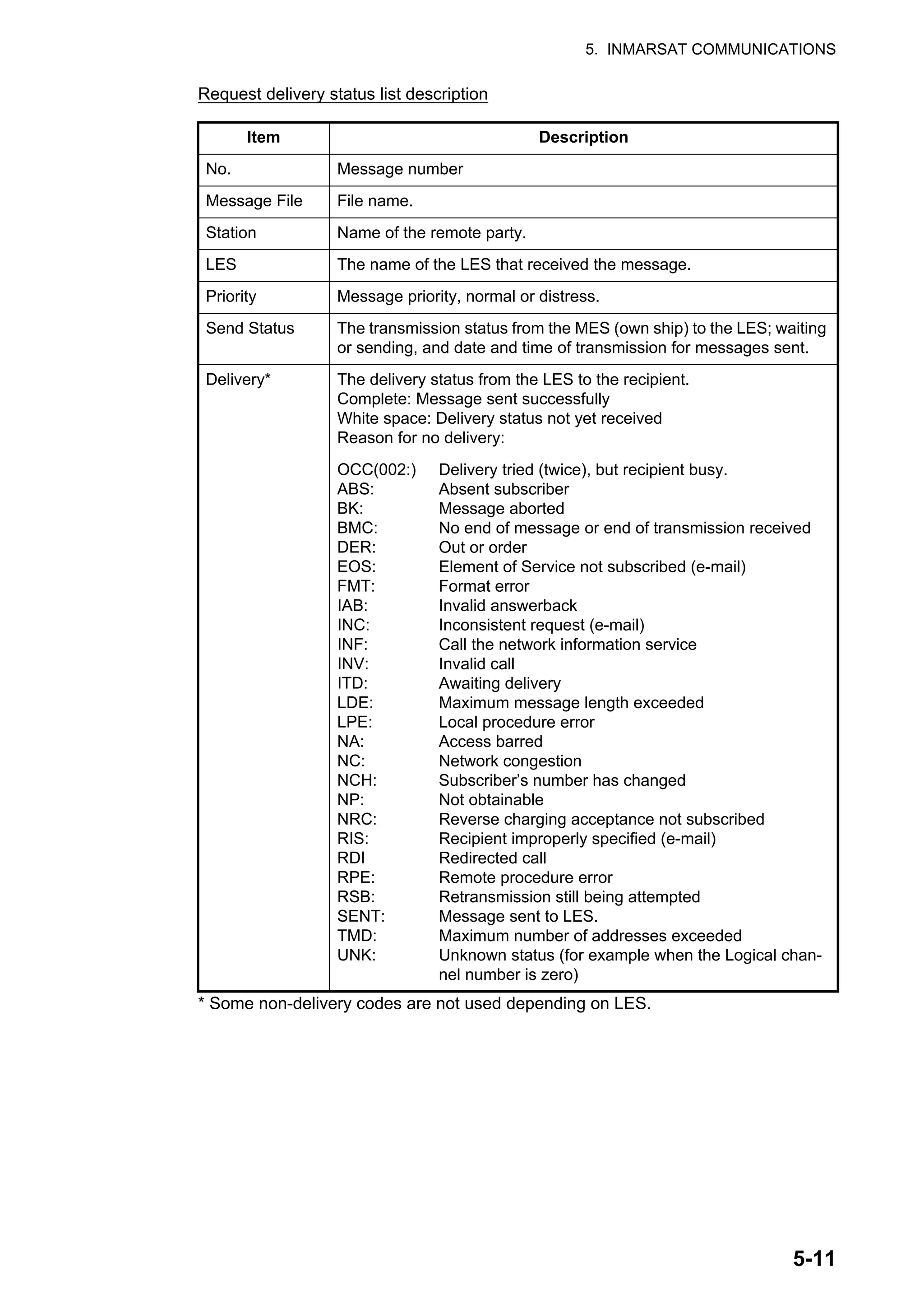
![5. INMARSAT COMMUNICATIONS
5-12
How to manually request delivery status
You can manually request an LES for delivery status of a message you have sent with-
in the past 24 hours.
1. Press the F3 and 3 keys to show the [Request Delivery Status] list. If there are no
messages in the list, "No message" appears.
2. Select a file then press the Enter key.
3. [Yes] is selected in the [Start] window; press the Enter key to request status. If
request was successful the message "Successful Delivery Status Request." ap-
pears.
4. Long-press the Esc key to return to the standby display.
Several minutes later the message "Delivery status received for (file name)" appears
on the display. The reply from the LES appears in the [Delivery] column of the [Re-
quest Delivery Status] list.
Request Delivery Status
No.
01
02
Message File
ABC
edit msg.002
Station
FURUNO
FURUNO
LES
KDDI
KDDI
Priority
Normal
Normal
Send Status
11-11-25 16:10
Delivery
Request Delivery Status
No.
01
02
Message File
ABC
edit msg.002
Station
FURUNO
FURUNO
LES
KDDI
KDDI
Priority
Normal
Normal
Send Status
11-11-25 16:10
Delivery
Start
No
Yes](https://image.slidesharecdn.com/felcom-18ome56740a2-220309163554/75/Felcom-18-ome56740-a_2-78-2048.jpg)
![5. INMARSAT COMMUNICATIONS
5-13
5.1.6 How to access the 2-digit code service
A range of special safety and general maritime services, known as the 2-digit code
services, may be sent. The list below shows the 2-digit code services available.
1. Use the text editor to prepare a message requesting a 2-digit code service.
2. Press the F3 and 1 keys to display the [Transmit Message] menu.
3. Select [Destination Type] then press the Enter key.
4. Select [Special] then press the Enter key.
5. Select [Destination] then press the Enter key.
6. Enter 2-digit code referring to the table below then press the Enter key.
7. Select [LES ID] then press the Enter key.
8. Select [LES ID] then press the Enter key.
Code Content Remarks
31 Maritime enquiries Request information including ser-
vice offerings.
32 Medical advice Request medical advice.
33 Technical assistance Address technical enquiries to ap-
propriate personnel.
37 Time and charges requested at end
of call
Desirable for mobile operator when
sending traffic for a third party.
38 Medical assistance Request medical assistance.
39 Maritime assistance Request maritime search and res-
cue assistance
41 Meteorological report Necessary for ease of addressing
weather reports from ship to meteo-
rological centers.
42 Navigational hazards and warnings Make urgent navigational meteoro-
logical danger reports.
43 Ship position reports Route messages to ship safety re-
porting systems.
1. Transmit Message
2. Cancel
3. Request Delivery Status
Transmit Message
Normal
Size 24
TELEX/MES
82
65-2111
303 (KDDI)
ON
00:00
Immediate
IA5
Priority
Message File
Station Name
Destination Type
Prefix Code
Country/Ocean Code
Destination
Modem Type
Address
Subject
Attach File
LES ID
Option
Confirmation
Send Delay
Delivery Delay
Code
[ TRANSMIT ]](https://image.slidesharecdn.com/felcom-18ome56740a2-220309163554/75/Felcom-18-ome56740-a_2-79-2048.jpg)
![5. INMARSAT COMMUNICATIONS
5-14
9. Select [TRANSMIT] then press the Enter key.
10. Press the Enter key to send the message.
Note: If some data is missing the message "Input error.xx" (xx: error) is displayed.
11. Long-press the Esc key to return to the standby display.
The message "Current State: SENDING" appears at the bottom of the screen during
transmission. If the message was sent successfully "Successful Sending message"
appears and the message is printed ([Confirmation] is turned ON). You can see the
contents on the [Display Log].
At present, not all LESs are offering the 2-digit code services. Contact the LES Oper-
ations Coordinator directly for information.
Some 2-digit code services may be provided free of charge by LESs, while other ser-
vices are available for a fee, in some cases at reduced rates. For information, contact
the LES directly.
5.1.7 Sent message log
The [Sent Message] log stores all messages sent. You can view the contents of the
log as shown below.
1. Press the F6 and 1 keys to show the [Sent Message] log.
2. Select a file then press the Enter key to show file contents.
3. Long-press the Esc key to return to the standby display.
Sent Message
Delivery
OCC(002)
Complete
Message File
ABC
DEF
GHI
JKL
MNO
No.
01
02
03
04
05
Destination
FURUNO
FURUNO
ASDFASDF
ABCDEFGH
LES
KDDI
KDDI
KDDI
KDDI
KDDI
Priority
Normal
Normal
Normal
Normal
Normal
Send Status
Waiting
Sending
11-11-26 9:40
11-11-25 20:16 Sent
11-11-23 16:09
[ENTER]: Show Detail
[Ctrl]+[E]: Export [Ctrl]+[P]: Print [Delete]: Delete
Number assigned by LES
Text
Destination : 870773999113](https://image.slidesharecdn.com/felcom-18ome56740a2-220309163554/75/Felcom-18-ome56740-a_2-80-2048.jpg)
![5. INMARSAT COMMUNICATIONS
5-15
5.2 Receiving
5.2.1 When a message is received
When the FELCOM receives a telex or e-mail successfully it displays the message
"Successful Receiving message." If [Auto Receive Message Save] and [Auto Receive
Message Print] (in the [Auto Mode Setup] menu) are set for ON, the message is auto-
matically saved and printed (except confidential and password-affixed messages).
Received message alarm
If [Receive Alarm] in the [Auto Mode Setup] menu is set for ON, the audio alarm
sounds when a telex or e-mail is received. You may silence the alarm with the F10 key.
Receive message format
Each message received is assigned a message number. This number is also used
when saving the file to an SD card.
Log
The [Communication Log] (see section 5.3) shows message number, priority, date
and time of reception, LES ID and file size (in bytes) of the latest 50 received and sent
messages.
Printing
When [Auto Receive Message Print] in the [Auto Mode Setup] menu is set for ON, re-
ceived messages (except confidential and password-affixed messages) are automat-
ically printed. Manual printing is also available.
Saving and filing
Received messages are filed in the [Display Message List], at the terminal unit spec-
ified with [Message Output Port] on the [System Setup] menu. The [Display Message
List] shows the following:
• Received message no.
• LES ID
• Priority
• File size (in bytes)
• Message classification
• Password for confidential messages
• Date and time of reception
• Status
R
Receive
0
0: main DTE
1: ext. DTE
1 1
year
1 2
month
2 5.
day
0 0 1
received
message no.](https://image.slidesharecdn.com/felcom-18ome56740a2-220309163554/75/Felcom-18-ome56740-a_2-81-2048.jpg)
![5. INMARSAT COMMUNICATIONS
5-16
5.2.2 How to set the receive alarm
You can get an audio alarm when a telex message
or e-mail is received. The default setting is OFF.
1. Press the F8 and 5 keys to show the [Auto
Mode Setup] menu.
2. Select [Receive Alarm] then press the Enter
key.
3. Select [ON] to get the audio alarm when a telex
message or e-mail is received then press the Enter key.
4. Long-press the Esc key to return to the standby display.
5.2.3 How to display and print received messages
Received messages (except confidential or password affixed) are automatically print-
ed when [Auto Receive Message Print] in the [Auto Mode Setup] menu is turned on.
To print confidential or password-affixed messages follow the procedure below.
If you cannot read an e-mail attachment, because it is MIME-coded, go to
section 4.10.
1. Press the F6 and 2 keys to display the [Received Message] log.
Contents of Received Message Log
Item Description Item Description
Message
No.
Received message no. Addressee Addressee code appears
for confidential messages.
Nothing appears for routine
message.
LES LES name Recdate &
Time
Date and time message
was received.
Priority Normal or Distress Status Printed, message printed;
Saved, message saved to
SD card or internal memo-
ry, No display, not yet print-
ed confidential message or
printer error
Size Size of file in bytes Memory
available
Memory available in termi-
nal unit
Auto Communication Log Print OFF
Receive Alarm OFF
Auto Receive Message Save OFF
Auto Receive Message Print OFF
Data Report & Polling Print OFF
Auto EGC Message Save
Auto EGC Message Print
Auto Mode Setup
Message No.
R0971106.001
R0971105.002
R0971105.001
R0971101.001
R0971024.001
LES
KDDI
KDDI
KDDI
KDDI
KDDI
Priority
Normal
Normal
Distress
Normal
Normal
Addressee
CAPTAIN
OFFICER
Rec date & time
02-02-04 16:10
02-02-05 17:30
02-02-05 14:15
02-02-01 3:45
02-01-24 13:20
Status
Saved
Printed
Printed
Printed
Saved
Memory Available: 3317 Bytes
Size
32767
200
1234
3256
8251
Received Message
[ENTER]: Show Detail
[Ctrl]+[E]: Export [Ctrl]+[P]: Print [Delete]: Delete](https://image.slidesharecdn.com/felcom-18ome56740a2-220309163554/75/Felcom-18-ome56740-a_2-82-2048.jpg)
![5. INMARSAT COMMUNICATIONS
5-17
2. Press the Enter key for routine messages and messages with addressee code
(no password).
For messages with both addressee code and password, the password entry win-
dow appears. Enter the password and then press the Enter key. If the password
is entered incorrectly, the buzzer sounds. Reenter the password.
3. To print a message, press the P key while pressing the Ctrl key.
4. Long-press the Esc key to return to the standby display.
Received Message Detail
FROM FURUNO
TO FRONTIER
THE QUICK BROWN FOX JUMPS OVER LAZY DOG.
ABCDEFGHIJKLMNOPQRSTUVWXYZ. 1234567890
[Ctrl]+[E]: Export [Ctrl]+[P]: Print [Ctrl]+[R]: Reply
Received Message
Message No.
R0021106.001
R0021105.002
R0021105.001
R0021101.001
R0021024.001
LES
KDDI
KDDI
KDDI
KDDI
KDDI
Priority
Normal
Normal
Distress
Normal
Normal
Addressee
CAPTAIN
OFFICER
Rec date & Time
02-11-06 16:10
02-11-05 17:30
02-11-05 14:15
02-11-01 3:45
02-10-24 13:20
Status
Saved
Printed
Printed
Printed
Saved
Memory Available: 3317 Bytes
Size
32767
200
1234
3256
8251
PASS WORD:
[ENTER]: Show Detail
[Ctrl]+[E]: Export [Ctrl]+[P]: Print [Delete]: Delete
Receive Message (SECRET)
Message No.
Message Ref. No.
LES
Priority
Message Size
Receive Date & Time
abcdefghijklmnopqrstuvwxyz........
: R0970323.001
: 00000000
: LES or LES ID
: Normal (or Distress)
: 205 characters
: 02-02-25
Appears only for confidential
messages
Text](https://image.slidesharecdn.com/felcom-18ome56740a2-220309163554/75/Felcom-18-ome56740-a_2-83-2048.jpg)
![5. INMARSAT COMMUNICATIONS
5-18
About attachments
The FELCOM receives a file with an attachment over a landline two ways. (The meth-
od depends on LES.)
• Mail main text and text mail which includes information about the attachment.
• Attachment data
Some files stored on the [Received Message] log may not be readable. Choose the
file then press the Enter key. If the file is unreadable, because it is in a language other
than English, press the Esc key to return to the [Received Message] log. Save the file
to an SD card by pressing the E key while pressing and holding down the Ctrl key. Try
to open the file from a PC.
5.2.4 How to automatically print received messages
You can automatically print received messages (except confidential and password-af-
fixed messages).
1. Press the F8 and 5 keys to show the [Auto Mode
Setup] menu.
2. Select [Auto Receive Message Print] then press
the Enter key.
3. Select [ON] to automatically print received mes-
sages then press the Enter key.
4. Long-press the Esc key to return to the standby
display.
Received Message
Message No.
R0021105.002
R0021105.001
R0021104.001
R0021101.001
R0021024.001
LES
KDDI
KDDIDDI
KDDI
KDDI
KDDI
Priority
Normal
Normal
Distress
Normal
Normal
Addressee
OFFICER
Rec date & Time
02-11-05 17:40
02-11-05 17:30
02-11-04 14:15
02-11-01 3:45
02-10-24 13:20
Status
Printed
Printed
Printed
Printed
Saved
Memory Available: 3317 Bytes
Size
18
210
1234
3256
8251
Mail and attachment file data
Attachment data
[ENTER]: Show Detail
[Ctrl]+[E]: Export [Ctrl]+[P]: Print [Delete]: Delete
One attachment
Received Message Detail
FROM : FURUNO
TO: FRONTIER
1 attachment
18 bytes, test
Text
[Ctrl]+[E]: Export [CTRL]+[P]: Print [Ctrl]+[R]: Reply
Attachment name
Auto Communication Log Print OFF
Receive Alarm OFF
Auto Receive Message Save OFF
Auto Receive Message Print OFF
Data Report & Polling Print OFF
Auto EGC Message Save
Auto EGC Message Print
Auto Mode Setup](https://image.slidesharecdn.com/felcom-18ome56740a2-220309163554/75/Felcom-18-ome56740-a_2-84-2048.jpg)
![5. INMARSAT COMMUNICATIONS
5-19
5.2.5 How to save received messages
1. Press the F6 and 2 keys to display the [Received Message] log.
2. Select the file to save. To confirm contents of a file, press the Enter key. For con-
fidential messages the password entry window appears after pressing the Enter
key. Enter the password then press the Enter key.
3. Press the E key while pressing and holding down the Ctrl key to save the file to
the SD card or the internal memory. For confidential messages the password en-
try window appears. Enter password then press the Enter key.
If the same file name is found on the SD card (internal memory), "File already exists.
Overwrite?" appears.
5.2.6 How to automatically save received messages
1. Press the F8 and 5 keys to show the [Auto Mode Setup] menu.
2. Select [Auto Receive Message Save] then press the Enter key.
3. Select [ON] to automatically save received messages then press the Enter key.
4. Long-press the Esc key to return to the standby display.
5.2.7 How to delete received messages
1. Press the F6 and 2 keys to display the [Received Message] log.
2. Select the file to delete. To confirm contents of a file, press the Enter key. For
password-affixed messages the password entry window appears. Enter the pass-
word then press the Enter key.
3. Press the Del key to delete the file. You are asked if you are sure to delete the
message file. For password-affixed messages, the password entry screen ap-
pears. Enter password then press the Enter key.
4. Press the Enter key to delete the message, or select [No] then press the Enter
key to escape.
5. Long-press the Esc key to return to the standby display.](https://image.slidesharecdn.com/felcom-18ome56740a2-220309163554/75/Felcom-18-ome56740-a_2-85-2048.jpg)
![5. INMARSAT COMMUNICATIONS
5-20
5.3 Communication Log
The Communication Log stores the particulars of the latest 50 received and sent mes-
sages. When the log becomes full, the oldest message is automatically deleted.
5.3.1 How to display and print the communication log
1. Press the F6 and 4 keys to display the [Communication Log].
2. To scroll the log, use the ↓ key.
3. To print the log, press the P key while pressing and holding down the Ctrl key. To
stop printing, press the Esc key.
Communication Log description
5.3.2 How to automatically print the communication log
1. Press the F8 and 5 keys to show the [Auto Mode Setup] menu.
2. Select [Auto Communication Log Print] then press the Enter key.
3. Select [ON] to automatically print the log then press the Enter key.
4. Long-press the Esc key to return to the standby display.
001 -:
S/R:
Cate:
Type:
Ch:
Ch-Num:
Pri:
LES
Size:
St:
Op. TIme:
Date & Time:
Log no.
S: Sent message, R: Received message
Category (MSG, EGC, DR, EDR, PADR, EPADR, POLL)
Message type (Telex, e-mail, etc.)
Channel type (TDM, SIG, etc.)
5-digit channel number
Priority, Normal or Distress
ID of LES that handled the message
Size of message (in Byte)
Communication results. S, Success; F, Failed
Total operating time (in sec) since commissioning
Date and time the message was sent.
Communication Log
No. S/R Cate Type Ch Ch-Num Pri LES Size St Op. Time Date & Time
001 S MSG TLX MSG 11100 Dis 322 10 S 0031104000 Dec-25-2011 17:46
002 R POLL DND TDM 11200 322 10 0031104061 Dec-25-2011 17:44
003 S DR DND SIG 11300 322 10 S 0031104122 Dec-25-2011 17:43
004
005
006
007
008
009
010
[Ctrl]+[P]: Print
- - - - - - - - - - - - - - - - - - - - - - - - - - - - - - - - - - - - - - - - - - - - - - - - - - - - - - - - - - - - - -
- - - - - - - - - - - - - - - - - - - - - - - - - - - - - - - - - - - - - - - - - - - - - - - - - - - - - - - - - - - - - -
- - - - - - - - - - - - - - - - - - - - - - - - - - - - - - - - - - - - - - - - - - - - - - - - - - - - - - - - - - - - - -](https://image.slidesharecdn.com/felcom-18ome56740a2-220309163554/75/Felcom-18-ome56740-a_2-86-2048.jpg)
![5. INMARSAT COMMUNICATIONS
5-21
5.4 EGC Messages
When an EGC message is received, "RECEIVING EGC MESSAGE" appears at the
bottom left corner of the display. If "Auto EGC Message Print" in the [Auto Mode Set-
up] menu is ON, EGC messages are automatically printed. EGC messages are auto-
matically received, printed and saved to the terminal unit selected with [EGC Output
Port] on the [System Setup] menu. The memory capacity for EGC messages is 32
Kbytes. When the EGC message memory becomes full, the oldest EGC message is
automatically deleted.
EGC messages can be automatically saved to an SD card or the internal memory. See
section 3.4.4 for details.
5.4.1 How to display and reprint EGC messages
1. Press the F4 and 1 keys to show the [Display EGC Message] screen.
2. Use the ↑ and ↓ keys to scroll the screen.
3. To print a message, press the P key while pressing and holding down the Ctrl key.
4. Long-press the Esc key to return to the standby display.
EGC messages can be automatically saved to an SD card. See section 3.4.4 for de-
tails.
5.4.2 How to display EGC closed network ID (ENID)
To join a FleetNET service, an MES must be registered with an information provider.
The information provider adds the MES to the group which is to receive the service,
by downloading a Group Call ID (via an LES which supports FleetNET broadcasts),
uniquely addressed to the MES. The MES stores the ID and can accept broadcasts
from the information provider. The MES operator cannot change this stored EGC
closed network IDs (ENIDs). Up to 64 ENIDs are stored on a non-volatile memory.
The ENID stored can be accessed for downloading and deleting via the satellite path.
An MES operator can inhibit (or activate as required), via the terminal unit, selected
ENIDs previously downloaded.
Along with the ENID the name of the information provider is stored. In the event that
a download command is received and the ENID storage area is full, an ENID which
: 00472
: KDDI
: Urgent
: 285 characters
: 02-11-02 06:08 (UTC)
Display EGC Message
EGC Message --- MET Navarea Warning or MET Forecast ---
Message Sequence No
LES
Priority
Size
Receive Date & Time
ZCZC
NAVAREA XI WARNING
NAVAREA XI 0752.
ARAFURA SEA.
DERELICT F/V PARTIALLY SUBMERGED ADRIFT
IN 10-12.6S 133-19.6E, GEODETIC DATUM
UNKNOWN, AT 180200Z NOV.
CANCEL 0749/02.
Ctrl+P: Print Ctrl+S: Save](https://image.slidesharecdn.com/felcom-18ome56740a2-220309163554/75/Felcom-18-ome56740-a_2-87-2048.jpg)
![5. INMARSAT COMMUNICATIONS
5-22
has been disabled by the MES operator will be written over. If none has been disabled,
then the new download is not accepted.
Follow the procedure below to inhibit or activate an ENID.
1. Press the F4 and 2 keys to show the [EGC Network ID] screen.
2. Select the ENID to enable or disable.
3. Press the Enter key to enable or disable the ENID as appropriate. The asterisk
disappears when an ENID is disabled.
4. Long-press the Esc key to return to the standby display.
5.4.3 How to receive EGC distress or urgent message
When the FELCOM receives an EGC distress or an urgent message, the audio alarm
sounds from its terminal unit, the Distress Alert/Received Call Unit IC-305 and Alarm
Unit IC-350. To silence the alarm, do the following:
FELCOM18: F10 (StopAlarm) key on the terminal unit
IC-350: MUTE ALARM button
5.4.4 How to display the EGC message log
1. Press the F6 and 3 keys to show the [EGC Message] log.
Scroll: ↑, ↓
Display message: Press the Enter key.
Save message: Press the E key while pressing and holding down the Ctrl key.
Delete message: Press the Delete key to show the Delete window. [Yes] is se-
lected; press the Enter key.
2. Long-press the Esc key to return to the standby display.
Ctrl+P: Print
Mark '*' means activation.
01
02
03
04
05
*
*
*
*
*
11111
22222
33333
44444
55555
EGC Network ID List
EGC Message
Message No. LES Priority Size Seq. No. Rec date&time Type
E0021118.028 KDDI Urgent 428 01641 11-11-25 10:27 MET/NAV
E0021118.028 KDDI Safety 428 02035 11-11-11 05:21 U.M Rct
Memory available: 32767 Bytes
_ _ _ _ _ _ _ _ _ _ _ _ _ _ _ _ _ _ _ _ _ _ _ _ _ _ _ _ _ _ _ _ _ _ _ _ _ _ _ _ _ _ _ _ _ _ _ _
[ENTER]: Show Detail
[Ctrl]+[E]: Export [Ctrl]+[P]: Print [Delete]: Delete](https://image.slidesharecdn.com/felcom-18ome56740a2-220309163554/75/Felcom-18-ome56740-a_2-88-2048.jpg)
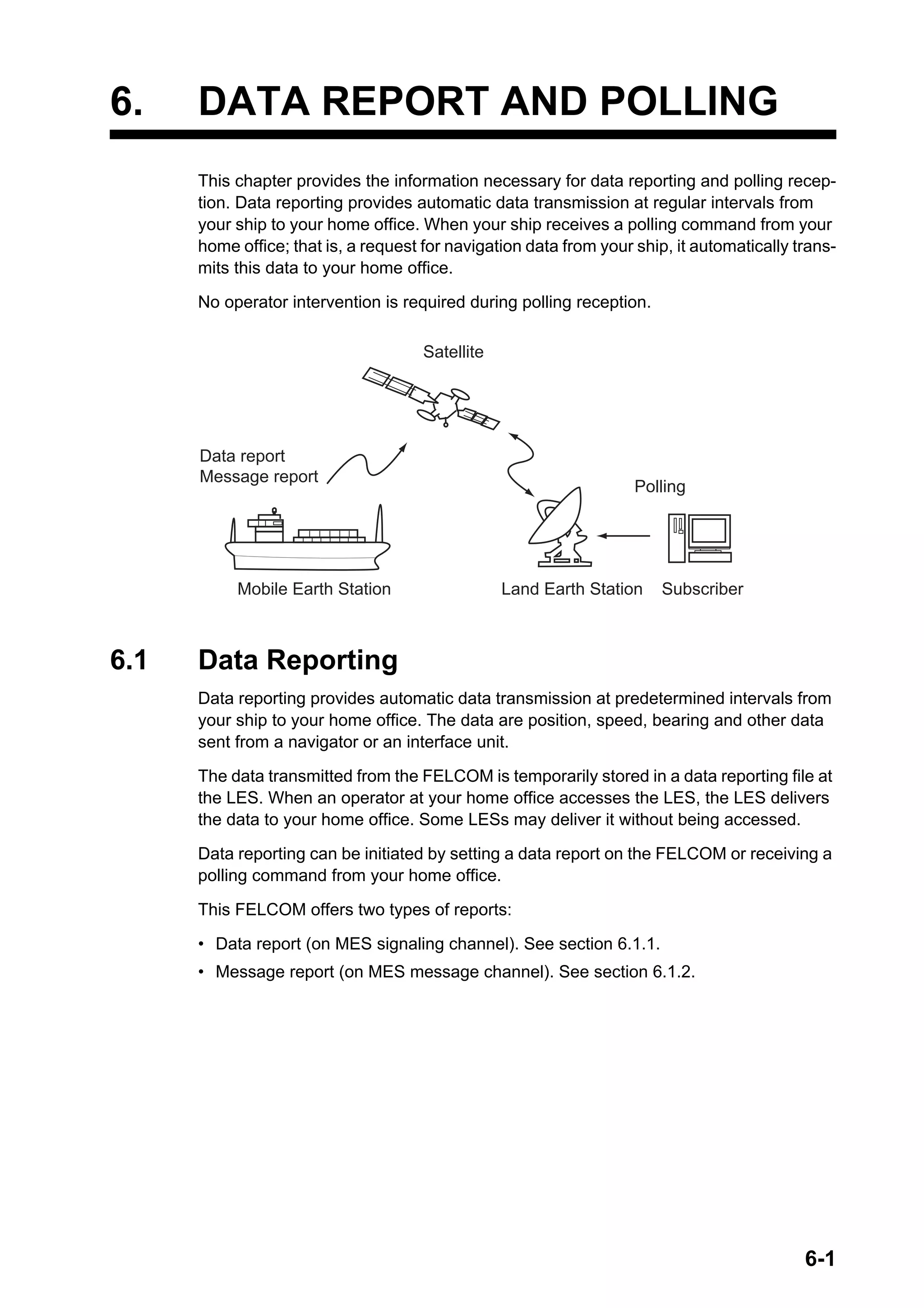
![6. DATA REPORT AND POLLING
6-2
6.1.1 How to prepare a data report
1. Press the F5 and 1 keys to show the [Data Report] menu.
2. Press the appropriate numeric key to select a data report.
3. [Status] is selected; press the Enter key to open the status options window.
4. Select appropriate option then press the Enter key.
OFF: Data report off
ON: Enhanced Data Report (Data report w/confirmation)
ON: Usual Data Report (Standard data report)
For assured transmission, select [ON: Enhanced Data Report].
5. Select [Report Length] then press the Enter key.
6. Select appropriate option then press the Enter key.
Position only: Own position
Position and Course/Speed: Position, course and speed
Position and Course/Speed with SEA INF: Position, course, speed, water tem-
perature, tide, and depth
7. Select [DNID] then press the Enter key.
8. Select DNID desired then press the Enter key. (LES ID and Member No. are au-
tomatically selected according to DNID.)
9. Select [Activation] then press the Enter key.
10. Select [Regular Interval] or [Daily] as appropriate then press the Enter key.
11. Do one of the following depending on selection made at step 10.
[Regular Interval] selected at step 10
1) Select [Interval Time] then press the Enter key.
2) Key in interval time then press the Enter key.
3) Select [Report Times] then press the Enter key.
4) Key in the report times, or press the BackSpace key to display “---” to select
[No Limit] to transmit data until the Status setting is turned OFF. Press the En-
ter key.
5) Press the Enter key to close the window.
[Daily] selected at step 10
1) Select [Start Time 1] then press the Enter key.
2) Key in the start time, in 24-hour notation, then press the Enter key.
3) If necessary, key in the start times 2-4.
12. Press the Esc key to show the [Update] window.
Data Report
1. Data Report 1
2. Data Report 2
3. Data Report 3
4. Data Report 4
Data Report
OFF
Position and Course/Speed
Regular Interval
00:10
1 (- - - : No Limit)
Data Report Programming
Status
Report Length
Destination
DNID
LES ID
Member No.
Activation
Interval Time
Report Times
Start Time1 - - : - -
Start Time2 - - : - -
Start Time3 - - : - -
Start Time4 - - : - -](https://image.slidesharecdn.com/felcom-18ome56740a2-220309163554/75/Felcom-18-ome56740-a_2-90-2048.jpg)
![6. DATA REPORT AND POLLING
6-3
13. [Yes] is selected; press the Enter key to register the settings.
14. Long-press the Esc key to return to the standby display.
6.1.2 How to prepare a message report
1. Press the F5 and 2 keys to show the [Message Report]
menu.
2. Press the appropriate numeric key to select a message re-
port.
PIN code is unrelated to message reporting, however it is necessary for polling
(see section 6.2). Enter PIN code as shown below.
3. [PIN Code] is selected; press the Enter key to open the PIN code entry window.
4. Key in PIN code, using up to eight digits, then press the Enter key. The PIN code
is a password used in message reports. When a ship receives a polling command
w/PIN code from a shore subscriber and the code matches that of the ship, the
ship sends a message report.
5. Select [Status] then press the Enter key.
6. Turn the message report ON or OFF as appropriate then press the Enter key.
7. Select [Station Name] then press the Enter key.
8. Select the station name then press the Enter key.
You may sort the list by group name, station name or communication type as fol-
lows:
Group name: Each press of Ctrl+G sorts the list by group name, ascending or
descending order.
Station name: Each press of Ctrl+N sorts the list by station name, in ascending
or descending order.
Comm. type: Each press of Ctrl+T sorts the list by communication type, in as-
cending or descending order.
9. For e-mail do step 1) and 2) below. For other communication formats, go to step
10.
1) Select [Subject] then press the Enter key.
Mesasge Report
1. Message Report 1
2. Message Report 2
3. Message Report 3
4. Message Report 4
Message Report
OFF
TELEX/MES
Regular Interval
00:10
1 (- - - : No Limit)
- - : - -
- - : - -
- - : - -
- - : - -
NAV
PIN Code
Message Report Programming
Status
Station Name
Destination Type
Prefix Code
Country/Ocean Code
Destination
Modem Type
Address
Subject
LES ID
Activation
Interval Time
Report Times
Start Time1
Start Time2
Start Time3
Start Time4
Report Contents
File](https://image.slidesharecdn.com/felcom-18ome56740a2-220309163554/75/Felcom-18-ome56740-a_2-91-2048.jpg)
![6. DATA REPORT AND POLLING
6-4
2) Key in the subject then press the Enter key.
10. Select [LES ID] then press the Enter key.
11. Select LES then press the Enter key.
12. Select [Activation] then press the Enter key.
13. Select [Regular Interval] or [Daily] as appropriate then press the Enter key.
14. Do one of the following depending on selection made at step 13.
[Regular Interval] selected at step 13
1) Select [Interval Time] then press the Enter key.
2) Key in interval time then press the Enter key.
3) Select [Report Times] then press the Enter key.
4) Key in the report times, or press the BackSpace key to display “---” to select
[No Limit] to transmit data until the Status setting is turned OFF. Press the En-
ter key.
[Daily] selected at step 13
1) Select [Start Time 1] then press the Enter key.
2) Key in the start time, in 24-hour notation, then press the Enter key.
3) If necessary, key in the start times 2-4.
15. Select [Report Contents] then press the Enter key.
16. Select required report contents then press the Enter key.
NAV: Position, speed, course
NAV+SEA INF: Position, speed, course, water temperature, current, depth
NAV(R): Position, speed, course. The difference between this and [NAV] above
is that blank areas in data are shortened to lessen toll charge.
FILE: Select a file. When selected [FILE] is activated, select the file then press the
Enter key.)
17. Press the Esc key to show the [Update] window.
18. [Yes] is selected; press the Enter key.
19. Long-press the Esc key to return to the standby display.
6.1.3 How to automatically print data report, polling command
1. Press the F8 and 5 keys to show the [Auto Mode
Setup] menu.
2. Select [Data Report & Polling Print] then press
the Enter key.
3. Select [ON] to automatically print data reports
and polling commands then press the Enter key.
4. Long-press the Esc key to return to the standby
display.
Auto Communication Log Print OFF
Receive Alarm OFF
Auto Receive Message Save OFF
Auto Receive Message Print OFF
Data Report & Polling Print OFF
Auto EGC Message Save
Auto EGC Message Print
Auto Mode Setup](https://image.slidesharecdn.com/felcom-18ome56740a2-220309163554/75/Felcom-18-ome56740-a_2-92-2048.jpg)
![6. DATA REPORT AND POLLING
6-5
6.2 Polling
When the FELCOM receives a polling command from your home office it automatically
transmits data to your home office. The data are position, speed, bearing and other
data sent from a navigator or an interface unit.
A polling command from your home office can also activate a data report or message
report if the corresponding setting is completed on the FELCOM. If a polling command
with a file name is received, the FELCOM transmits the file to your home office.
6.2.1 Polling commands
This section shows you how to make the polling command at your home office.
There are two kinds of polling commands: one is sent on the MES signalling channel
and the other is sent on the MES message channel.
Polling command on the MES signalling channel
Request a land station to make the polling command because the format varies with
land station.
Polling command on the MES message channel
To make the polling command, enter D???, hy-
phen, PIN code (max. 8 digits), hyphen, file name,
colon.
To send file data, type a hyphen and file name.
Then, only the file specified in the directory of the
Message Directory is transmitted. If neither hy-
phen nor file name is entered, nav data (own ship
position, course, speed, etc.) is transmitted.
How to register your PIN code
The PIN (Personal ID Number) code is a password used in message reporting, and is
an eight-digit number agreed upon by communicating parties. There is no rule for de-
termining PIN code. When a ship receives a polling command w/PIN code from a
shore subscriber and the code matches that of the ship, the ship sends a message
report.
1. Press the F5 and 2 keys to show the [Message Report] menu.
2. Press the 1, 2, 3 or 4 key to select a message report and show the following menu.
3. [PIN Code] is selected; press the Enter key to open the PIN code entry window.
4. Enter PIN code number (max. 8 digits) then press the Enter key.
5. Follow the procedure from step 5 on page 6-3.
D???-XXXXXXXX-TEST:
PIN Code
File Name
Message Report
OFF
PIN Code
Message Report Programming
Status
Station Name](https://image.slidesharecdn.com/felcom-18ome56740a2-220309163554/75/Felcom-18-ome56740-a_2-93-2048.jpg)
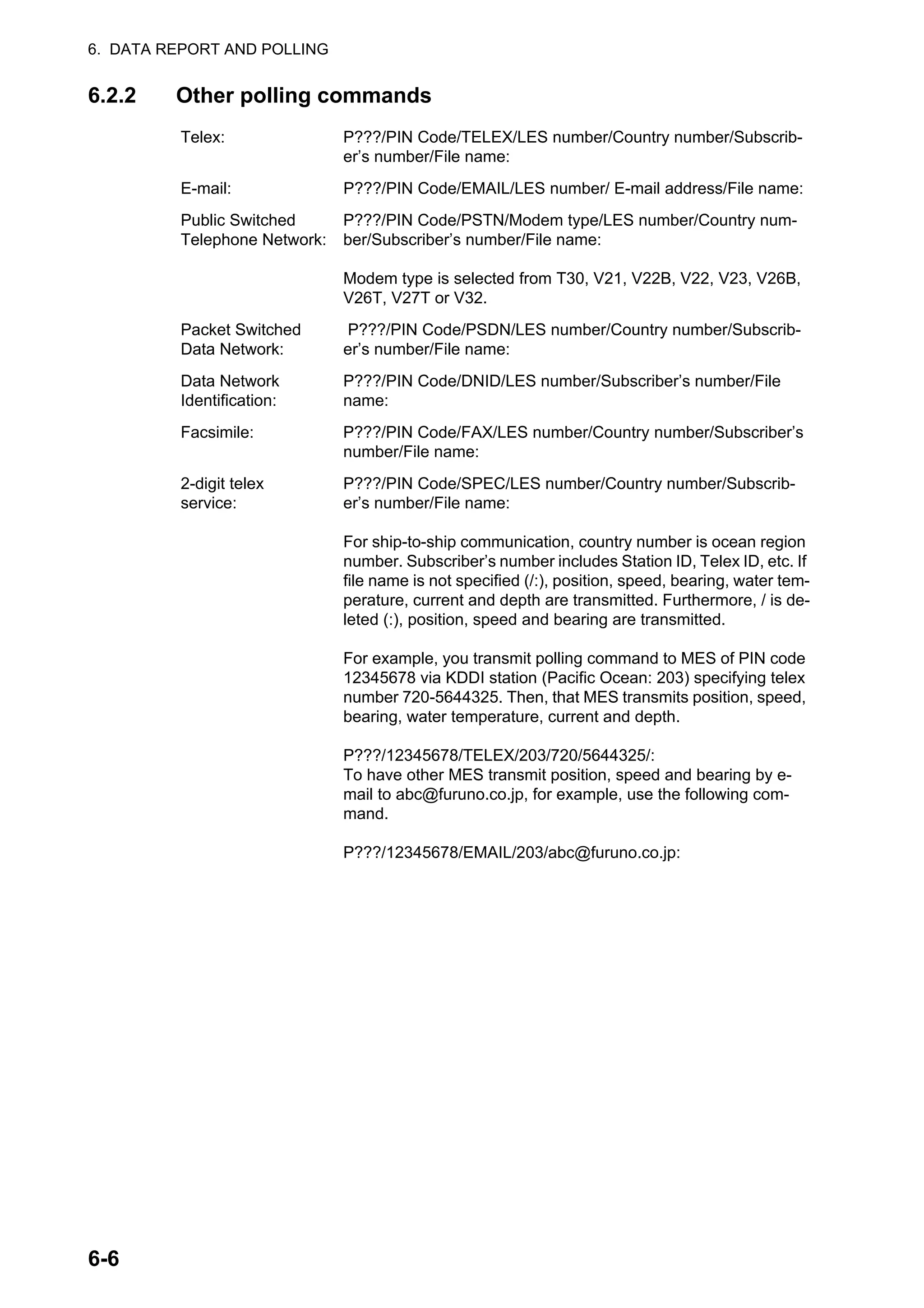
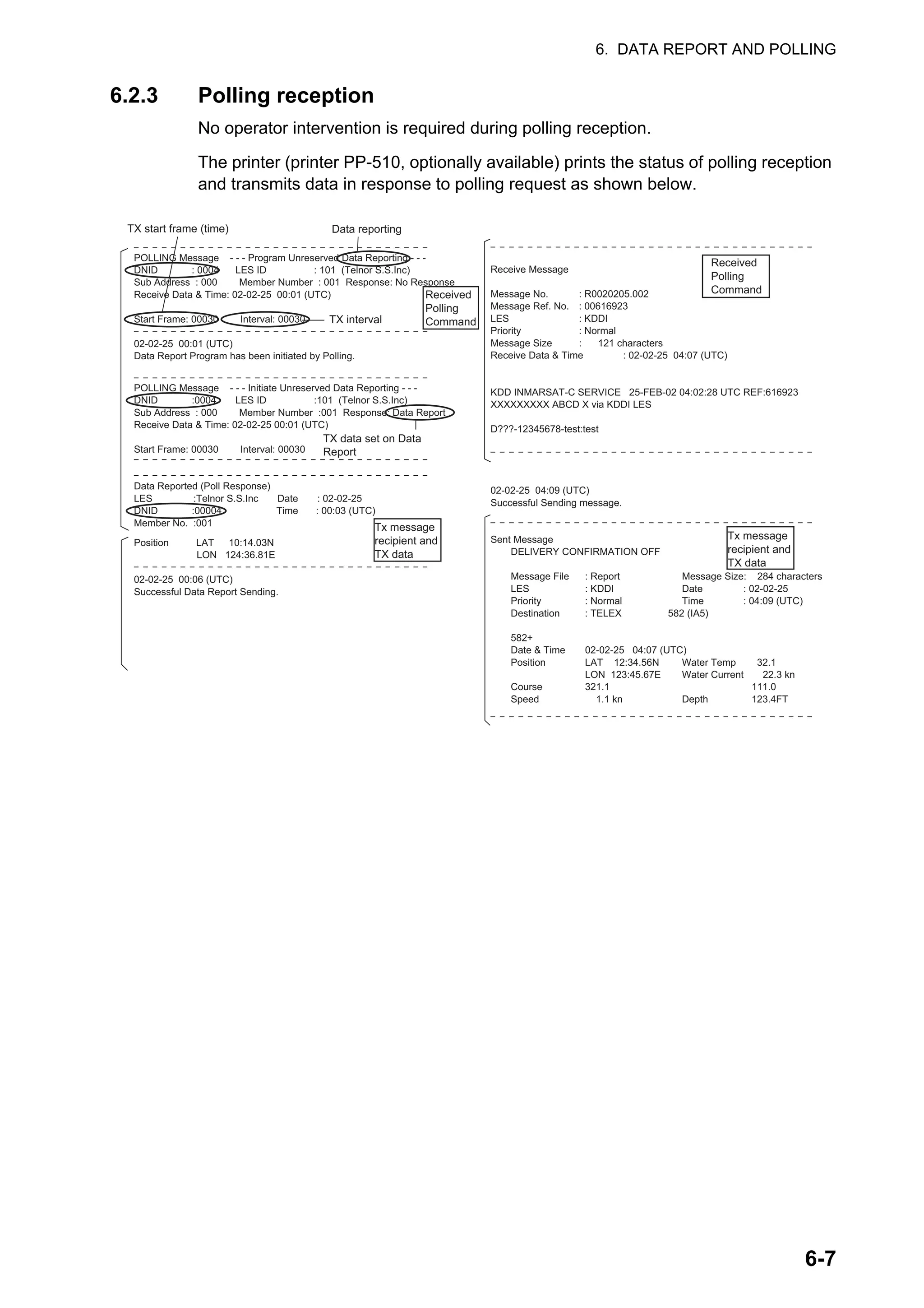
![6. DATA REPORT AND POLLING
6-8
6.3 DNID (Data Network Identification)
When you make a contract with an information provider, DNIDs are downloaded from
the information provider to the FELCOM, via the appropriate LES.
Up to 64 DNIDs can be downloaded to the FELCOM. You can see which DNIDs are
stored by following the procedure shown below.
6.3.1 How to display DNIDs
You need to make a contract with an LES to exchange data within a group. The LES
sends a DNID (Data Network Identification) number to each member of the group. The
FELCOM can store a maximum of 64 DNIDs.
Press the F5 and 4 keys to show the [Data Network ID] list.
“Act” indications and their meanings
Asterisk: Enabled DNID
No indication means disabled DNID.
24h: Enabled DNID. TX cycle changes every 24 hours.
STP: Enabled DNID. TX temporarily disabled.
6.3.2 How to enable, disable DNIDs
A DNID can be enabled or disabled as follows:
1. Press the F5 and 4 keys to show the [Data Network ID] list.
2. Select the DNID to process then press the Enter key. A password input screen
appears. Enter the password provided by the LES. The screen shown below ap-
pears. (If the password is wrong, the password input screen closes.)
3. Select applicable item then press the Enter key.
Disable: DNID disabled, Enable: DNID enabled
Enable (24-hour): DNID enabled (TX cycle changes every 24 hours.)
Enable (Temporary Stop): DNID enabled (TX temporarily stopped)
4. The [Update] window appears. [Yes] is selected; press the Enter key.
Data Network ID
Mark '*' means activation. Ctrl+P: Print
No.
01
02
03
04
05
06
07
08
Act
*
24h
STP
*
24h
STP
DNID
01000
01001
01002
01003
01004
01005
01006
01007
LES
002
001
102
131
202
210
302
304
Subaddr
000
001
002
003
004
000
001
002
Member
235
085
215
033
227
013
079
089
Text
Sub address Member number using DNID
Disable
Enable
Enable (24-hour)
Enable (Temporary Stop)](https://image.slidesharecdn.com/felcom-18ome56740a2-220309163554/75/Felcom-18-ome56740-a_2-96-2048.jpg)
![6. DATA REPORT AND POLLING
6-9
6.4 EPADR (Enhanced Pre-Assigned Data
Reporting)
EPADR increases the efficiency of maritime data reporting, allowing vessels using
satellite services to reliably send position reports and comply with the International
Maritime Organization's (IMO) new Long Range Identification and Tracking (LRIT)
regulations.
6.4.1 How to prepare a data report
1. Press the F5 and 3 keys to show the [EPADR] menu.
2. Press the appropriate numeric key to select a data report. For example, press the
1 key to select [EPADR 1].
3. [Status] is selected; press the Enter key to open the status options window.
4. Select appropriate option then press the Enter key.
OFF: Data report off
ON: Data report on
5. Select [Report Length] then press the Enter key.
6. Select appropriate option then press the Enter key.
Position only: Own position
Position and Course/Speed: Position, course and speed
Position and Course/Speed and SEA INF: Position, course, speed, water tem-
perature, tide, and depth
7. Select [DNID] then press the Enter key.
8. Select DNID desired then press the Enter key. (LES ID and Member No. are au-
tomatically selected according to DNID.)
9. Select [Interval Time] then press the Enter key.
10. Select an interval (15 min, 30 min, 1 hr, 3 hrs, 4 hrs, 6 hrs, 8 hrs) then press the
Enter key.
11. Select [Report Times] then press the Enter key.
12. Enter the number of times to transmit then press the Enter key. (Data is transmit-
ted only the number of times specified.)
EPADR1
Status ON
Report Length Position and Course/Speed
Destination
DNID 21100
LES ID 203
Member No. 020
Activation Regular Interval
Interval Time 1 hour
Report Times 600
Requested by LES
Enhanced Pre-Assigned Data Report (EPADR) Programming](https://image.slidesharecdn.com/felcom-18ome56740a2-220309163554/75/Felcom-18-ome56740-a_2-97-2048.jpg)
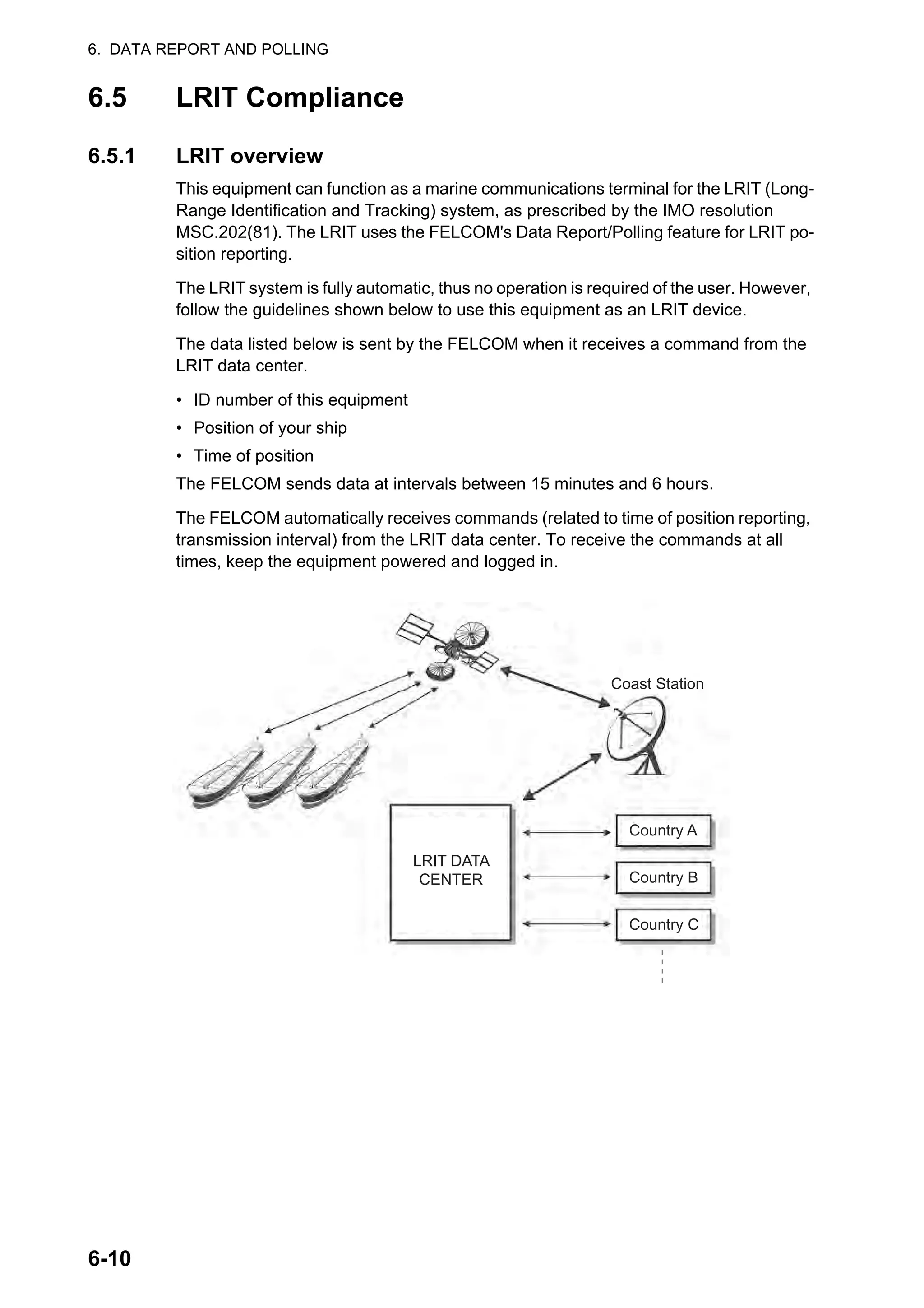
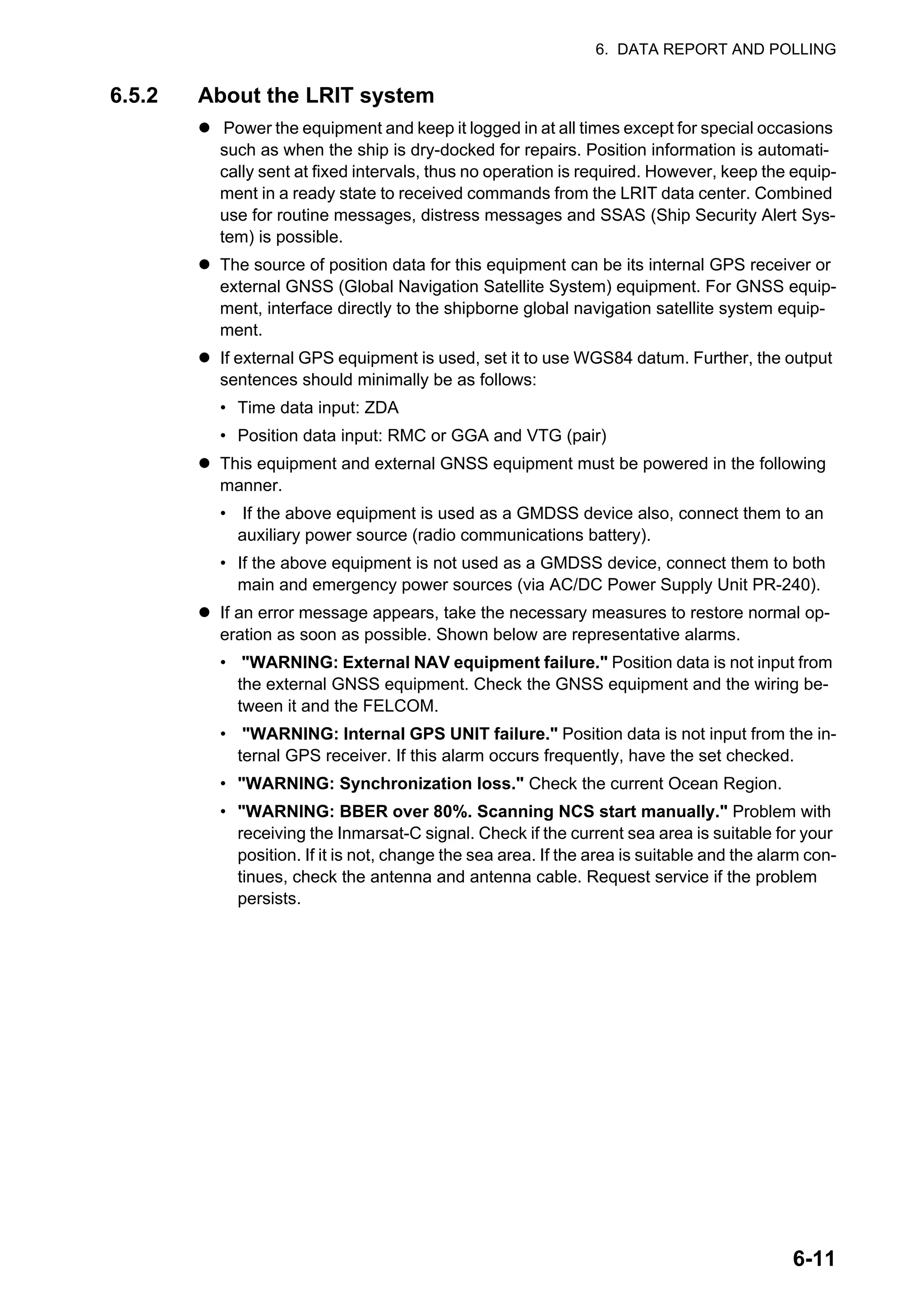

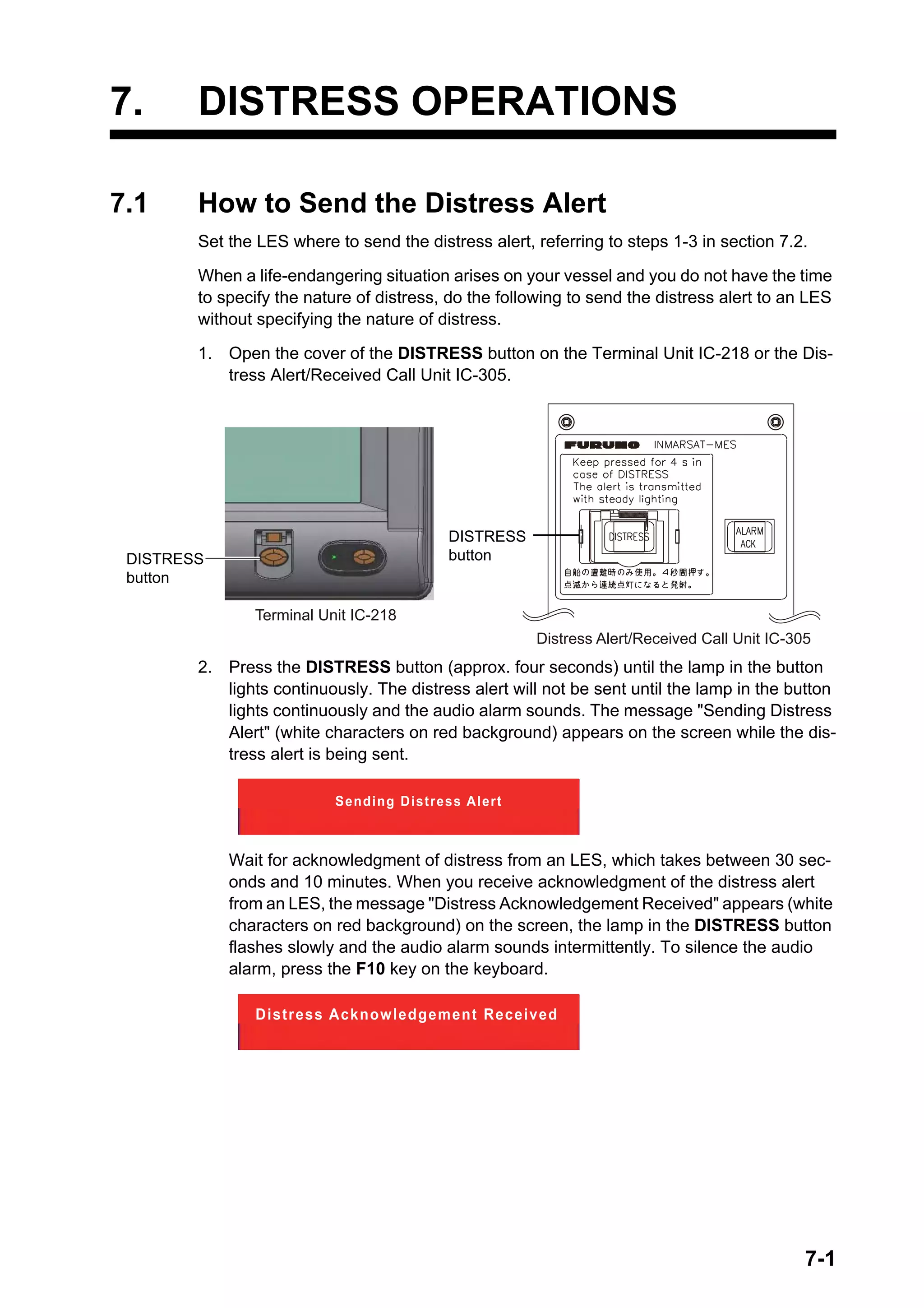
![7. DISTRESS OPERATIONS
7-2
The state of the LED in the DISTRESS button and the buzzer change according to the
events in the distress transmission sequence.
The DISTRESS button on the terminal unit of the FELCOM or the Distress Alert/Re-
ceive Call Unit IC-305 cannot be used to silence the audio alarm for incoming distress
or EGC urgency broadcast. The DISTRESS button is for sending a distress alert
for own ship. It cannot be used to silence the audio alarm. Use the F10 key on
the keyboard to silence the audio alarm.
7.2 How to Send the Distress Alert with Nature of
Distress Specified
When a life-endangering situation arises on your vessel and there is time to specify
the nature of distress and the recipient (LES) of the distress alert, send own ship data
(position, time, speed and course) as follows:
1. Press the F9 key to display the [Distress Alert Setup] screen.
2. [LES ID] is selected; press the Enter key.
3. Select a suitable LES then press the Enter key.
4. Select [Update Time] then press the Enter key.
5. Enter the current time then press the Enter key.
6. Select [Position] then press the Enter key.
7. Enter your current position in latitude and longitude then press the Enter key. Use
the S, N, E and W keys to enter appropriate coordinate.
Note: [Protocol] is fixed at [Maritime].
8. Select [Nature] then press the Enter key.
9. Enter applicable nature of distress then press the Enter key. If the nature of dis-
tress is not specified, [Undesignated] is automatically selected.
10. Select [Course] then press the Enter key.
11. Enter your course then press the Enter key.
12. Select [Speed] then press the Enter key.
13. Enter your speed then press the Enter key.
Event in
distress TX sequence
LED state Buzzer state
Idle OFF OFF
Distress TX Lighting Continuous
Distress ACK 1.2 s ON, 0.3 s OFF 1.2 s on, 0.3 s OFF
Distress Alert Setup
LES ID
Update Time
Position
Protocol
Nature
Course
Speed
303 (KDDI)
06:23 02-02-25 (YY-MM-DD)
LAT 35:00N
LON 135:00E
Maritime
Undesignated
187
10 kn](https://image.slidesharecdn.com/felcom-18ome56740a2-220309163554/75/Felcom-18-ome56740-a_2-102-2048.jpg)
![7. DISTRESS OPERATIONS
7-3
14. Press the Esc key to show the [Update] window.
15. [Yes] is selected; press the Enter key to register settings.
Note: If incorrect data is entered, Update is cancelled and previous data is re-
stored.
16. Open the cover of the DISTRESS button on the Terminal Unit IC-218 or the Dis-
tress Alert/Received Call Unit IC-305.
17. Press the DISTRESS button (approx. four seconds) until the lamp in the button
lights continuously. The distress alert will not be sent until the lamp in the button
lights continuously and the audio alarm sounds. The message "Sending Distress
Alert" appears on the screen while the distress alert is being sent. When you re-
ceive acknowledgment of the distress alert from an LES, the message "Distress
Acknowledgement Received" appears on the screen, the lamp in the DISTRESS
button flashes slowly and the audio alarm sounds intermittently. To silence the au-
dio alarm, press the F10 key on the keyboard.
The DISTRESS button on the terminal unit of the FELCOM or the Distress Alert/Re-
ceive Call Unit IC-305 cannot be used to silence the audio alarm for incoming distress
or EGC urgency broadcast. The DISTRESS button is for sending a distress alert
for own ship. It cannot be used to silence the audio alarm. Use the F10 key to
silence the audio alarm.](https://image.slidesharecdn.com/felcom-18ome56740a2-220309163554/75/Felcom-18-ome56740-a_2-103-2048.jpg)
![7. DISTRESS OPERATIONS
7-4
7.3 How to Prepare the Distress Message
The distress alert provides the minimum distress information: own vessel’s ID, speed,
course, L/L position and nature of distress. After receiving the distress alert acknowl-
edgment from an LES and you are not pressed for time, you may send a distress mes-
sage as below to provide more detailed information.
1. Press the F1 and 1 keys to open a message screen.
2. Type the distress message. Below is an example.
3. Press the F3 and 1 keys to select [Transmit Message].
4. [Priority] is selected; press the Enter key.
5. Select [Distress] then press the Enter key.
6. Select [LES ID] then press the Enter key.
7. Select the LES where to send the distress message, preferably to the one where
the distress alert was sent, then press the Enter key.
8. Select [TRANSMIT] (at the bottom of the screen) then press the Enter key.
9. The [Start] window appears and [Yes] is selected; press the Enter key to send the
distress message.
The message "Distress Message Call Activated." appears (in red) while the distress
message is being sent. When you receive acknowledgment from an LES, the mes-
sage" Distress Message Call Acknowledged." appears and flashes.
Country/Ocean Code and Station ID are not required in a distress message.
MAYDAY MAYDAY MAYDAY
THIS IS
I NEED HELP
Ship's name
: Type of assistance required
1. Transmit Message
2. Cancel
3. Request Delivery Status
Transmit Message
Normal
Size 24
TELEX/MES
82
65-2111
303 (KDDI)
ON
00:00
Immediate
IA5
Priority
Message File
Station Name
Destination Type
Prefix Code
Country/Ocean Code
Destination
Modem Type
Address
Subject
Attach File
LES ID
Option
Confirmation
Send Delay
Delivery Delay
Code
[ TRANSMIT ]](https://image.slidesharecdn.com/felcom-18ome56740a2-220309163554/75/Felcom-18-ome56740-a_2-104-2048.jpg)
![7. DISTRESS OPERATIONS
7-5
7.4 How to Test the DISTRESS Button
The DISTRESS button on the terminal unit and the Distress Alert/Received Call Unit
IC-305 may be tested as shown below without sending the distress signal. Note that
the distress alert cannot be sent while testing the DISTRESS button.
1. Press the F7 key to show the [Options] menu.
2. Press the 8 key to select [Test].
3. Press the 4 key to select [Distress Button Test]. [Yes] is selected in the [Start] win-
dow; press the Enter key to start the distress button test. The buzzer sounds re-
peatedly, signifying the start of the test mode. Further, the message "Distress
buttons are under test. Cancel the test mode if a real distress alert needs to sent."
appears (in red).
4. Open the DISTRESS button cover.
5. Press the DISTRESS button four seconds. The buzzer sounds rapidly for three
seconds and then sounds repeatedly, as in step 3. The message "Distress Button
works correctly." appears if the button is working properly.
6. Close the DISTRESS button cover.
7. To escape from the test, press the Esc key on the keyboard of the terminal unit
twice. The test mode alarm stops and the message shown below appears to notify
you that normal operation has been restored.
8. Long-press the Esc key to return to the standby display.
Options
1. Position
2. Login
3. Logout
4. Abort
5. Select NCS
6. Ocean Region
7. LES Information
8. Test
9. Maintenance
FELCOM functions as
Inmarsat MES
Options
1. Position
2. Login
3. Logout
4. Abort
5. Select EGC Ch.
6. Ocean Region
7. LES Information
8. Test
9. Maintenance
FELCOM functions as
EGC receiver
Test
1. PV Test
2. PV Test Result
3. Diagnostic Test
4. Distress Button Test
CAUTION
INF: Distress Buttons entered into TEST MODE.
<Press ESC key to continue>
CAUTION
INF: Distress Buttons returned to NORMAL OPERATION.
<Press ESC key to continue>](https://image.slidesharecdn.com/felcom-18ome56740a2-220309163554/75/Felcom-18-ome56740-a_2-105-2048.jpg)

![8-1
8. OTHER FUNCTIONS
This chapter describes how to
8.1 How to Abort an Operation
You can abort transmission, receiving or scanning (on the NCS common channel) as
follows:
1. Press the F7 and 4 keys to show the [Options] menu and select [Abort].
2. The [Start] window appears and [Yes] is selected; press the Enter key to abort
current operation.
The message "FORCED CLEARING" replaces "SENDING" or "RECEIVING" at the
bottom of the screen. When the process has been aborted, the message "Process
Aborted. Press any key to escape." appears.
If aborting is attempted in modes other than those mentioned above, the message
"Ignored: Can not abort current process." appears.
8.2 How to Scan NCS Common Channels
Scanning is possible when the FELCOM is in idle state and functions as an Inmarsat
C receiver. If the FELCOM is not in idle state, the message "Ignored: MES is not idle."
appears. Wait until the equipment becomes idle.
1. Press the F7 and 6 keys to display the [Ocean Region] menu.
2. Select a NCS other than the one currently in use then press the Enter key. [Auto]
scans all regions in turn.
3. [Yes] is selected; press the Enter key to start the scanning.
4. Long-press the Esc key to return to the standby display.
• Abort operation
• Scan NCS
• Select EGC and NCS channels
• Display LES information
1. Login
2. Logout
3. Abort
4. Select NCS
5. Ocean Region
6. Test
Ocean Region
Auto
West-Atlantic
East-Atlantic
Pacific
Indian
NCS you are currently tuned to
appears in reverse video.](https://image.slidesharecdn.com/felcom-18ome56740a2-220309163554/75/Felcom-18-ome56740-a_2-107-2048.jpg)
![8. OTHER FUNCTIONS
8-2
8.3 How to Select EGC Receiving Channel
EGC channel can be selected when the terminal unit is set to operate as an EGC-only
receiver. However, this procedure is shown for reference only; currently there is only
one EGC channel per NCS.
1. Press the F7, 5 and 3 keys to display the [EGC Channel List].
2. Select a desired channel then press the Enter key.
3. Long-press the Esc key to return to the standby display.
8.4 How to Select NCS Channel
You may select NCS common channel as shown below. Currently, each satellite
sends one global beam. In the future, the satellites will transmit multiple spot beams,
namely, the NCS will have multiple channels.
1. Press the F8, 8 and 4 keys to display the [NCS Channel List].
2. Select a desired channel then press the Enter key.
3. Long-press the Esc key to return to the standby display.
35:00.00N
135:00.00E
EGC Channel List
12580* 10840* 11088*
ENTER: Set ESC: Quit
11080*
NCS Channel List
No AOR (WEST)
FREQ
11080*
ID
044
0
0
0
0
0
0
0
01
02
03
04
05
06
07
08
ENTER: Set ESC: Quit
AOR (EAST)
FREQ
12580*
ID
144
1
1
1
1
1
1
1
POR
FREQ
12580*
ID
244
2
2
2
2
2
2
2
IOR
FREQ
10840*
ID
344
3
3
3
3
3
3
3](https://image.slidesharecdn.com/felcom-18ome56740a2-220309163554/75/Felcom-18-ome56740-a_2-108-2048.jpg)
![8. OTHER FUNCTIONS
8-3
8.5 How to Find LES Information
Each time you log in LES data is automatically downloaded through the NCS common
channel to the FELCOM, and saved to the LES Information display. You may view this
display as follows:
1. Press the F7 and 7 keys to display the [LES Information] screen.
2. Use the ↑ and ↓ keys to scroll the list.
3. Long-press the Esc key to return to the standby display.
Description of status
Bit No. Status Flag Meaning
B8 Return link speed 1 600 bps
0 300 bps
B7 Operational or spare
satellite operation
1 Operational
0 Spare
B6 LES status 1 In service
0 Out of service
B5 LES status 1 Clear
0 Congested
B4 For LES use 1 Terrestrial links open
0 Terrestrial links closed
B3-1 Spare 1
0
LES ID Name Status Services TDM Ch.
201 Telnor S.S.Inc 11111000 AS-----EL 11982
202 Stratos M.N. 11111000 AS-----EL 11826
203 KDDI 11111000 AS-----EL 11806
204 Telnor S.S.AS 11111000 AS-----EL 11762
208 Korea Telecom 11111000 AS-----EL 11778
210 Singapore T. 11111000 AS-----EL 11842
211 Beijing Marine 11111000 AS-----EL 11754
212 Xantic 11111000 AS-----EL 11802
LES Information
B8-B1](https://image.slidesharecdn.com/felcom-18ome56740a2-220309163554/75/Felcom-18-ome56740-a_2-109-2048.jpg)
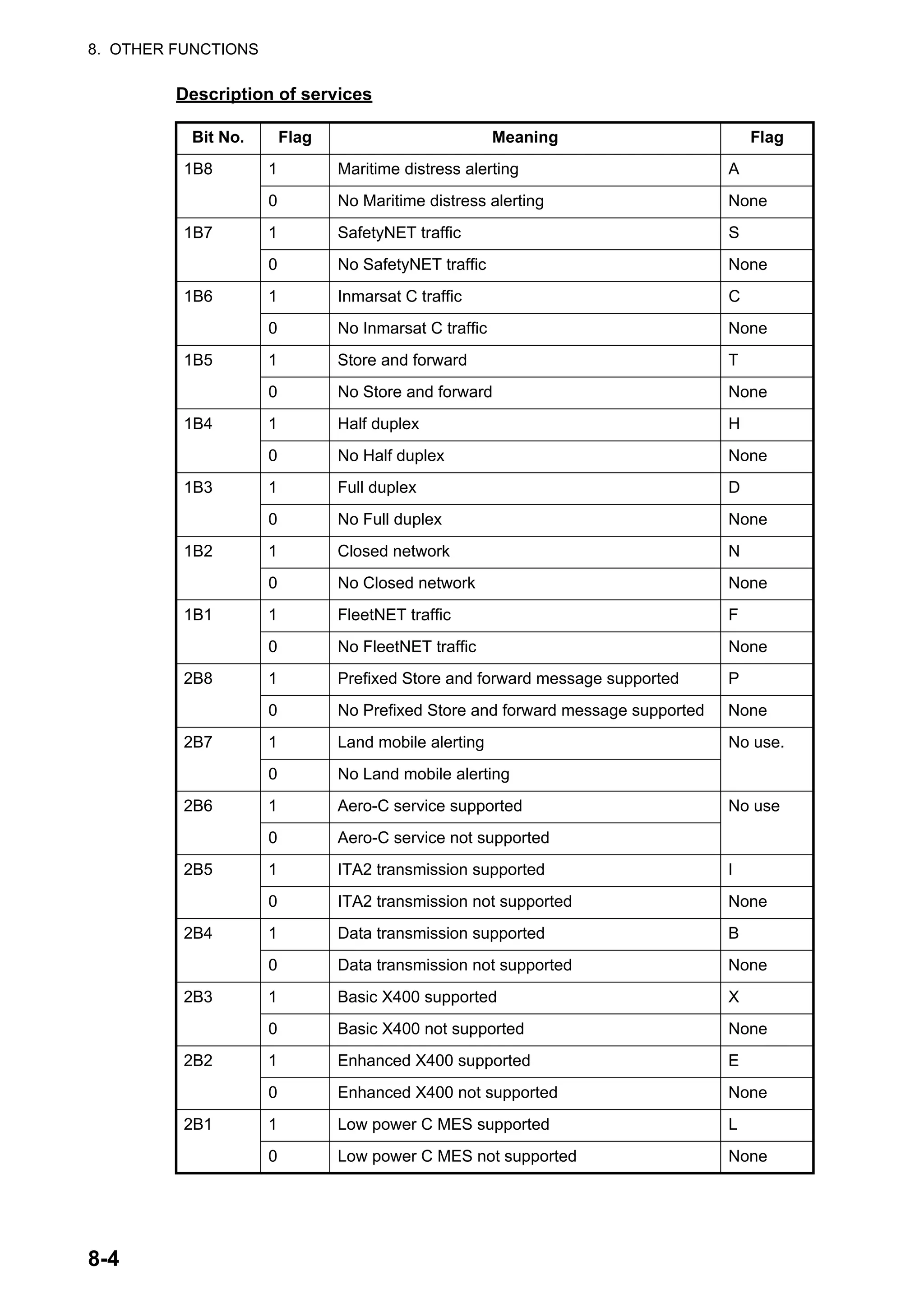
![9-1
9. E-MAIL BY PC
9.1 Introduction
This FELCOM incorporates various e-mail protocols including POP3 and SMTP. Con-
nected to a LAN via the Ethernet(10Base-T) port on a PC, the FELCOM can send and
receive e-mail using the PC’s e-mail application, for example, Outlook®
Express.
9.1.1 Overview of mail functions
• Mail gateway
Received mail may be forwarded to a specific mail server.
• Selective forwarding
Received mail which contains a keyword can be forwarded to the mail address
which appears after the keyword in a message.
• Access restriction
A specific PC on a network can be designated to send mail.
• Automatic attachment decoding
MIME-encoded mail sent from a network can be automatically decoded by UUEN-
CODE or BINARY decoding format.
• Outgoing message size restricting
The administrator of this FELCOM can specify maximum outgoing message size
(Max. size 32KB) allowable for the PC e-mail client. This allows control over the size
of mail messages which can be sent by the PC e-mail client.
9.1.2 E-mail restrictions
The Inmarsat C e-mail system has restrictions not found on the land-based e-mail sys-
tem. Further there are some restrictions which apply to this FELCOM.
• Use 7-bit characters in the Subject field, text and attachment. Some LES may not
use 8-bit characters (Japanese, etc.). Since most LES use 7-bit characters in the
header, 8-bit characters may not be properly received.
Space ( 0 8 @ H P X ` h p x
! ) 1 9 A I Q Y a i q y
” * 2 : B J R Z b j r z
# + 3 ; C K S [ c k s {
$ , 4 < D L T d l t |
% - 5 = E M U ] e m u }
& . 6 > F N V ¯ f n v ~
’ / 7 ? G O W _ g o w](https://image.slidesharecdn.com/felcom-18ome56740a2-220309163554/75/Felcom-18-ome56740-a_2-111-2048.jpg)
![9. E-MAIL BY PC
9-2
• The maximum number of simultaneous transmissions is 32. Any simultaneous
transmission in excess of that amount will not be sent. When transmitting, wait until
the message "Successful Sending message." appears before transmitting another
message.
• The maximum number of characters available for the Subject field is 60.
• The maximum number of characters per line is 1000. Characters in excess of 1000
will not be sent. Use maximum 1000 character per line.
• The maximum number of multiple addressees is 10. Any number in excess of that
amount will not be sent.
• Destination cannot be specified as “Bcc:”. “Bcc:” is automatically changed to “Cc:”
because Bcc is not used in Inmarsat C.
• Set the encoding format on the PC’s e-mail client to BASE64.
9.1.3 E-mail characteristics
• Confirm the port chosen to output received messages from the FELCOM. Set the
[Message Output Port] on the [System Setup] menu to [INT] or [Auto].
• Set the mail format at the e-mail client for “Text.” HTML increases communication
charges because of its large size.
• The FELCOM does not have account management functions, for example, multiple
accounts.
• All received and sent messages (incl. those on a LAN) are saved to the communi-
cations log. The log may be printed in real time or when desired.
• Sending and receiving stations should use the same font to read each others’ mes-
sages. Use of different fonts may result in unreadable characters.
• When a file with an attachment is sent from land, the LES (e-mail service provider)
separately forwards the file and attachment to the intended MES. The file name for
the attachment as received at the FELCOM “ATTACH.DAT.” For that reason re-
quest that land-based e-mail with attachment contain the attachment file name in
the text of the message.
• File and accompanying attachment are sent separately regardless of the delivery
address specified with the auto delivery keyword. The message file is delivered ac-
cording to the auto delivery keyword setting and the attachment goes to the Mail Ad-
dress set on Mail Gateway.](https://image.slidesharecdn.com/felcom-18ome56740a2-220309163554/75/Felcom-18-ome56740-a_2-112-2048.jpg)
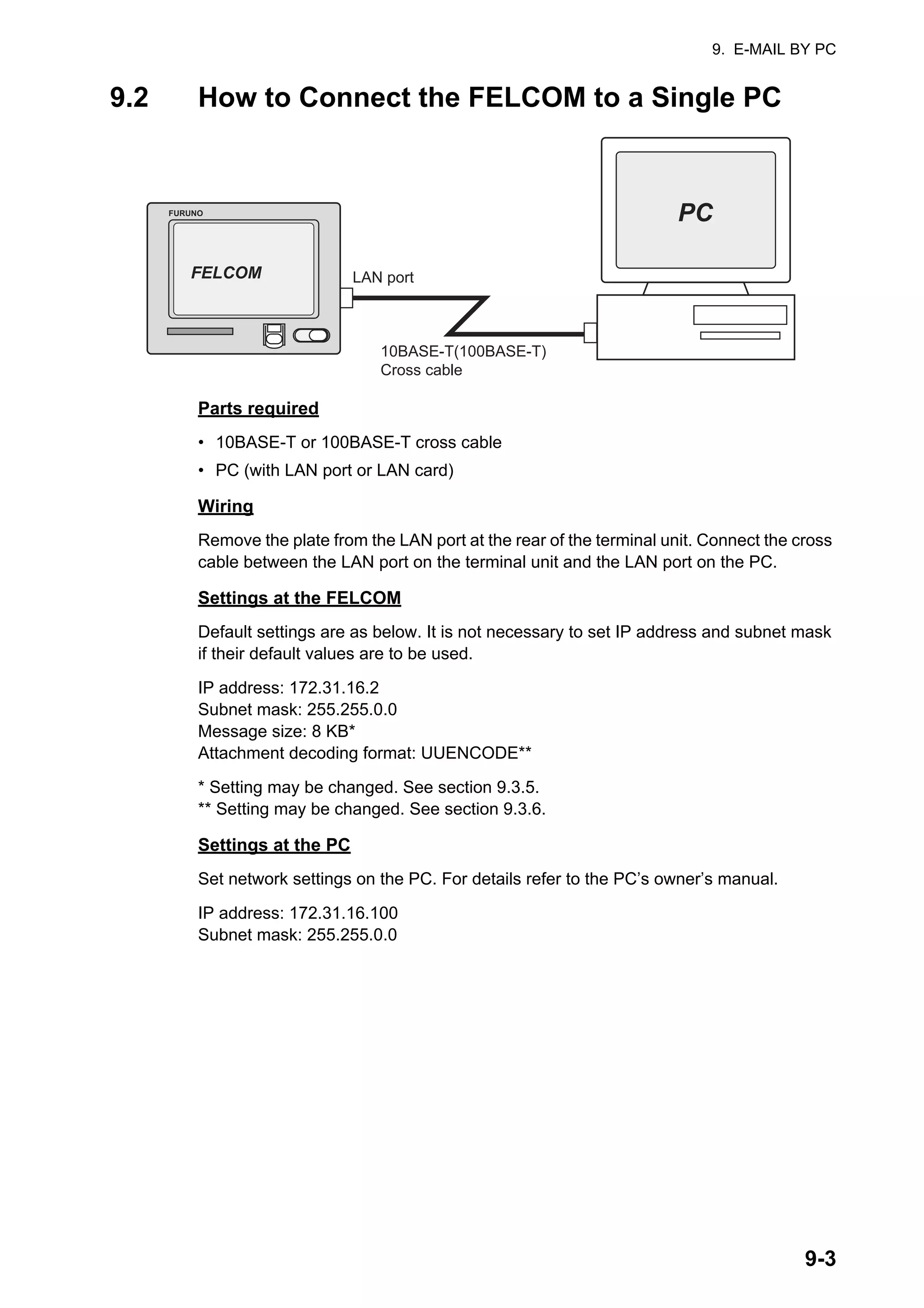
![9. E-MAIL BY PC
9-4
9.3 Function Settings
For network setting, consult your shipboard LAN administrator.
9.3.1 How to set IP address and subnet mask
Set IP address and subnet mask as below if they are different from their default set-
tings, in case that DHCP is off.
1. Press the F8 and 1 keys to show the [System Setup] menu.
2. Select [Network Setup] then press the Enter key.
3. Select [Network] then press the Enter key.
4. [IP Address] is selected; press the Enter key.
5. Enter IP address then press the Enter key.
6. Select [Subnet Mask] then press the Enter key.
7. Enter subnet mask then press the Enter key.
8. Press the Esc key to show the [Update] window.
9. [Yes] is selected; press the Enter key. If you changed the IP address a message
asks you to restart the FELCOM. Press the Esc key to restart the FELCOM. If only
the subnet mask setting was changed go to the next step.
10. Long-press the Esc key to return to the standby display.
Network
IP Address 172. 31. 16. 1
Subnet Mask 255. 255. 0. 0
DHCP OFF
Gateway . . .](https://image.slidesharecdn.com/felcom-18ome56740a2-220309163554/75/Felcom-18-ome56740-a_2-114-2048.jpg)
![9. E-MAIL BY PC
9-5
9.3.2 DHCP setting
1. Press the F8 and 1 keys to show the [System Setup] menu.
2. Select [Network Setup] then press the Enter key.
3. Select [Network] then press the Enter key.
4. Select [DHCP] then press the Enter key.
5. Select [ON] then press the Enter key.
6. Press the Esc key to show the [Update] window.
7. [Yes] is selected; press the Enter key. A message asks you to restart the FEL-
COM.
8. Long-press the Esc key to return to the standby display.
9. The terminal unit is restarted. After restarting is completed, confirm that IP ad-
dress and subnet mask have been assigned.
LAN port
FURUNO
FELCOM
PC
PC
HUB
10BASE-T(100BASE-T)
Straight cable
10BASE-T(100BASE-T)
Straight cable
DHCP Server](https://image.slidesharecdn.com/felcom-18ome56740a2-220309163554/75/Felcom-18-ome56740-a_2-115-2048.jpg)
![9. E-MAIL BY PC
9-6
9.3.3 Gateway setting
1. Press the F8 and 1 keys to show the [System Setup] menu.
2. Select [Network Setup] then press the Enter key.
3. Select [Network] then press the Enter key.
4. Select [Gateway] then press the Enter key.
5. Enter the gateway address then press the Enter key.
6. Press the Esc key to show the [Update] window.
7. [Yes] is selected; press the Enter key. A message asks you to restart the FEL-
COM.
8. Press the Esc key to restart the FELCOM.
FURUNO
FELCOM
HUB
PC
PC
PC
HUB
Router
Network 1
Network 2
LAN Port
PC
PC PC](https://image.slidesharecdn.com/felcom-18ome56740a2-220309163554/75/Felcom-18-ome56740-a_2-116-2048.jpg)
![9. E-MAIL BY PC
9-7
9.3.4 How to restrict access
Specify the IP address of the PC which is to be used to send and receive e-mail. A PC
not specified cannot send e-mail but it can receive e-mail. If no IP address is specified,
all PCs connected to the LAN can send and receive e-mail.
For example, the IP address of the PC allowed to perform e-mail functions is
172.31.16.5. Then, only that PC on the LAN can send mail.
1. Press the F8 and 1 keys to show the [System Setup] menu.
2. Select [Network Setup] then press the Enter key.
3. Select [Mail Gateway] then press the Enter key.
4. Select [SMTP Enable IP address] then press the Enter key.
5. Enter IP address of PC which is to send e-mail then press the Enter key.
6. Press the Esc key to show the [Update] window.
7. [Yes] is selected; press the Enter key.
8. Long-press the Esc key to return to the standby display.
FURUNO
FELCOM
PC
PC PC PC
172.31.16.2
172.31.16.5
172.31.16.4
172.31.16.3
172.31.16.2
Can send mail
OK
Sent mail is rejected
Cannot
send
mail
Cannot
send
mail
Cannot
send
mail
Mail Gateway
SMTP Enable IP Address . . .
Send Limit Size (KB) 8
Attach UUENCODE
Delivery To Server
Server IP . . .
Address Mode FIXED
Mail Address
Auto Delivery Keyword](https://image.slidesharecdn.com/felcom-18ome56740a2-220309163554/75/Felcom-18-ome56740-a_2-117-2048.jpg)
![9. E-MAIL BY PC
9-8
9.3.5 How to restrict the size of outgoing messages
The FELCOM administrator may limit the size of outgoing messages. When a PC cli-
ent attempts to send an e-mail message which is larger than permitted, the message
"Data size too large" appears and the message is not sent.
Attachments are encoded, which increases messages by 1.5 times.
1. Press the F8 and 1 keys to show the [System Setup] menu.
2. Select [Network Setup] then press the Enter key.
3. Select [Mail Gateway] then press the Enter key.
4. Select [Send Limit Size (KB)] then press the Enter key.
5. Select the maximum message size to send within shipboard LAN, among 2, 4, 6,
8, 10, 16 and 32 (KB), then press the Enter key.
6. Press the Esc key to show the [Update] window.
7. [Yes] is selected; press the Enter key.
8. Long-press the Esc key to return to the standby display.
9.3.6 How to automatically convert attachments
Using the default setting, mail (MIME encoded) sent from a PC in a network is encod-
ed with UUENCODE. For Inmarsat C use UUENCODE.
If the intended receiver does not use UUENCODE, an attachment may be unreadable.
In this case, change the encode format to BINARY and re-send the message. In the
BINARY setting the attachment file name is not sent to the receiver. To switch to BI-
NARY follow the procedure below.
Some LES do not use the BINARY format. Contact your LES for details.
1. Press the F8 and 1 keys to show the [System Setup] menu.
2. Select [Network Setup] then press the Enter key.
3. Select [Mail Gateway] then press the Enter key.
4. Select [Attach] then press the Enter key.
5. Select the encoding format (UUENCODE or BINARY) then press the Enter key.
6. Press the Esc key to show the [Update] window.
7. [Yes] is selected; press the Enter key.
8. Long-press the Esc key to return to the standby display.](https://image.slidesharecdn.com/felcom-18ome56740a2-220309163554/75/Felcom-18-ome56740-a_2-118-2048.jpg)
![9. E-MAIL BY PC
9-9
9.3.7 How to connect the FELCOM to the shipboard LAN mail server
When a mail server is installed on a LAN, received mail is forwarded to the mail server
via the LAN. The illustration on the next page shows how mail is forwarded to the mail
server.
Mail server: 172.32.16.10
LAN domain name: ship.furuno.co.jp
Forwarding mail address: felcom@ship.furuno.co.jp (IP Address: 172.31.16.2)
If there is no mail server, disregard the procedure below.
1. Press the F8 and 1 keys to show the [System Setup] menu.
2. Select [Network Setup] then press the Enter key.
3. Select [Mail Gateway] then press the Enter key.
4. Select [Delivery To] then press the Enter key.
5. Select the location where to deliver e-mail then press the Enter key.
PC Mailer: A mail-dedicated PC is connected to the FELCOM. The mail received
by the FELCOM can be read by the PCs.
Server: The FELCOM is connected to mail server connected to a LAN. Mail re-
ceived by the FELCOM is forwarded to the mail server.
6. Select [Server IP] then press the Enter key.
7. Enter server IP address then press the Enter key.
8. Select [Address Mode] then press the Enter key.
9. Select [Fixed] or [Auto] as appropriate and then press the Enter key.
Auto: When the keyword (entered in Auto Delivery Keyword) is found in the text
of a message, the message is sent to the address which appears after the key-
word. If the keyword is not found the mail is delivered to “Mail Address.”
Fixed: Message is sent mail address specified in Mail Address.
10. Select [Mail Address] then press the Enter key.
11. Enter the IP address of the PC where the e-mail server is to forward e-mail then
press the Enter key.
12. Press the Esc key to show the [Update] window.
13. [Yes] is selected; press the Enter key. The message "Press ESC key to Restart
FELCOM18." appears.
14. Press the Esc key to restart.](https://image.slidesharecdn.com/felcom-18ome56740a2-220309163554/75/Felcom-18-ome56740-a_2-119-2048.jpg)
![9. E-MAIL BY PC
9-10
9.3.8 Selective forwarding
When a keyword is found in a message the message is forwarded to the address
which appears after the keyword. For example, the keyword is “g/+forward+/fel-
com@ship.furuno.co.jp”. The keyword “+forward” is found and the message is then
forwarded to felcom@ship.furuno.co.jp.
To use selective forwarding with a land-based subscriber, you should request the
land-based subscriber to do the following:
• Insert the keyword and mail address on the first line of the message.
• Do not insert a space in the keyword or mail address.
• Maximum number of mail addresses is 10.
1. Press the F8 and 1 keys to show the [System Setup] menu.
2. Select [Network Setup] then press the Enter key.
3. Select [Mail Gateway] then press the Enter key.
4. Select [Delivery To] then press the Enter key.
5. Select the location where to deliver e-mail then press the Enter key.
PC Mailer: A mail-dedicated PC is connected to the FELCOM. The mail received
by the FELCOM can be read by the PCs.
Server: The FELCOM is connected to mail server connected to a LAN. Mail re-
ceived by the FELCOM is forwarded to the mail server.
6. Select [Server IP] then press the Enter key.
FURUNO
FELCOM
PC
PC PC
Domain name;
ship.furuno.co.jp
POP3
- USER : felcom
- Password : xxxxx
POP3
- USER : smith
- Password : xxxxx
POP3
- USER : 4431099010
- Password : xxxxxxxxx
Incoming
E-Mail message
Forwarding all
e-mail messages
172.31.16.1
172.31.16.10
172.31.16.2
172.31.16.3
172.31.16.4
Mail Server
MSG. 1
MSG. 3
MSG. 1
MSG. 2
MSG 1 MSG2 MSG3
To: ****@***.***
Subject: ……..
Test mail
/+forward+/443 109910@ship.furuno.co.jp
This is test message……
To: ****@***.***
Subject: ……..
Test mail
This is test message……
To: ****@***.***
Subject: ……..
Test mail
/+forward+/felcom@ship.furuno.co.jp
/+forward+/smith@ship.furuno.co.jp
This is test message……](https://image.slidesharecdn.com/felcom-18ome56740a2-220309163554/75/Felcom-18-ome56740-a_2-120-2048.jpg)
![9. E-MAIL BY PC
9-11
7. Enter server IP address then press the Enter key.
8. Select [Address Mode] then press the Enter key.
9. Select [Auto] then press the Enter key. ([Fixed] delivers messages to the PC
specified in [Mail Address].)
10. Select [Mail Address] then press the Enter key.
11. Enter the mail address corresponding to the mail server which is to receive mail
then press the Enter key. Mail that does not have the keyword will be sent to this
address.
12. Select [Auto Delivery Keyword] then press the Enter key.
13. Enter auto delivery keyword. Enter characters (incl. symbol) not normally found in
your e-mail documents. Maximum 15 characters may be entered. Upper and low-
er case letters are not distinguished in the search for keyword.
14. Press the Esc key to show the [Update] window.
15. [Yes] is selected; press the Enter key. A message asks you to restart the FEL-
COM.
16. Press the Esc key to restart the FELCOM.
9.3.9 Example of how to set e-mail client
For network settings contact your LAN administrator. See the owner’s manual of the
PC for how to set up for communications via a LAN. The settings in the table are ap-
plicable when [Delivery To] in the [Mail Gateway] menu is set to [PC Mailer].
Item Setting Remarks
POP3 server FELCOM’s IP
address
POP3 port no. 110 Cannot be changed.
SMTP server FELCOM’s IP
address
SMTP port no. 25 Cannot be changed.
User account IMN no. Cannot be changed.
POP3 password IMN no. Cannot be changed.
Mail Address Mail address of LES
used for communi-
cations
The receiver is not informed of the
mail address. The e-mail station thru
which the e-mail was forwarded is
sent to the receiver.
Signature Any Signature is not passed to the
receiver.
Check-for-incoming-mail
interval
Two minutes The FELCOM’s capacity for
message storage is 32 KB. When the
capacity is reached the oldest mes-
sage is deleted to make room for the
latest.](https://image.slidesharecdn.com/felcom-18ome56740a2-220309163554/75/Felcom-18-ome56740-a_2-121-2048.jpg)
![9. E-MAIL BY PC
9-12
9.4 SMTP Error Messages
The table below shows the SMTP error messages which may appear when commu-
nication error between the FELCOM and the e-mail client is found. Check the e-mail
client whenever an SMTP error message appears.
Message Meaning
Current LES out of service area. Selected service provider is not within current
ocean area.
Data size too large. Size of message is larger than set with [Send
Size Limit] on the [Mail Gateway] menu.
Illegal address. Invalid character(s) used in delivery address,
or invalid domain name (no period entered).
Mail data abnormal. Abnormal mail header
No target address. Delivery address has not been set.
Send message parameter mismatch. Address parameter error
Send message type mismatch. Address parameter error
Sorry, system busy now. The Tx message queue is full.
Too many addresses The number of delivery addresses is more
than the system can handle.
Your address access denied. The SMTP Enable IP Address is on.](https://image.slidesharecdn.com/felcom-18ome56740a2-220309163554/75/Felcom-18-ome56740-a_2-122-2048.jpg)
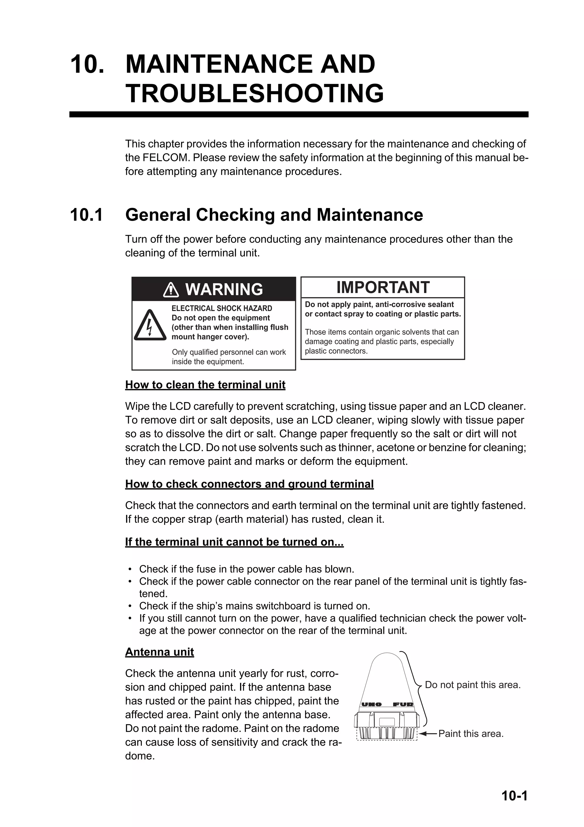
![10. MAINTENANCE AND TROUBLESHOOTING
10-2
10.2 Diagnostics
10.2.1 Self test at power on
The terminal unit performs the ROM sum test and RAM read and write test at power
up. If the test results are normal the equipment goes into standby. If error is found you
cannot transmit.
10.2.2 Diagnostic
This test can only be initiated from the main terminal, and it must be idle state to do
the test.
1. Press the F7 and 8 keys to show the [Test] menu.
2. Press the 3 key to select [Diagnostic Test].
3. The [Start] window appears and [Yes] is selected;
press the Enter key to start the test.
When the test is completed, the screen shows the test
results.
4. Press the Esc key to stop the test and return to the [Test] menu.
(1) Date and time of test
(2) Date and time of most recent TX and RX and the power output and current level
at that time.
(3) Various levels and indications. See page 10-5 for description.
(4) Status of equipment connected to the system.
(5) Status of GPS navigator
(6) Results for ROM, RAM and EEPROM check (OK: Normal, NG: No Good)
(7) Program version of CPU in Terminal Unit
Test
1. PV Test
2. PV Test Result
3. Diagnostic Test
4. Distress Button Test
TERMCPU 1650247-xx*
ROM OK
RAM OK
EEPROM OK
GPS State INT 2D OK
FELCOM18 12-02-02 20:30 (UTC)
Diagnostic Test
REMOTE BOX
1. SSAS ON 2. IC-305 ON 3. IC-306 OFF 4. IC-306 ON
5. IC-306 OFF
MAIN STATE
BBER 000[%] RxTx Data: 12/02/02 20:30 (UTC)
C/N 40[dB] Tx Power Supply
Rx AGC Level 107 current Level
REF offset Freq 0[Hz] Rx Power Supply 7.7[V]
Synthe Local OK / OK current Level 102
TCXO Control 2535 / 1771
(7)
(6)
(5)
(4)
(3)
(1)
(2)
*xx=Version no.](https://image.slidesharecdn.com/felcom-18ome56740a2-220309163554/75/Felcom-18-ome56740-a_2-124-2048.jpg)
![10. MAINTENANCE AND TROUBLESHOOTING
10-3
10.3 Performance Verification (PV) Test
After the FELCOM is installed, the installer usually confirms that it is functioning prop-
erly, by logging in and conducting the PV test. This test consists of receiving a test
message from an LES, transmitting a message to the LES and a distress alert test.
The results of the test appear on the PV test result display.
The PV test cannot be conducted from an auxiliary terminal unit. Note that the test can
also be initiated by an NCS.
10.3.1 PV test sequence
1. Select [PV Test] from the [Test] menu.
2. The MES requests an NCS to conduct the PV test.
3. The NCS acknowledges request for testing.
4. The MES, upon receiving acknowledgment from NCS, goes into pending state.
5. The NCS selects an LES to perform the test.
6. The LES transmits a test message to the MES.
7. The LES receives the test message.
8. The MES automatically transmits the distress alert test within two minutes after
completion of step 7.
9. When the distress alert test is finished, the LES sends the results of the PV test
to the MES.
10.3.2 PV test procedure
1. Confirm that the terminal unit is in idle condition and is logged in.
2. Press the F7, 8, and 1 keys to enable the PV test.
3. The [Start] window appears and [Yes] is selected; press the Enter key to start the
test. The [PV Test] screen appears and shows the message "Starting PV Test
Process. Press any key to escape."
Note: If the terminal unit is not idle when the test is initiated, the screen displays
"Ignored: MES is not idle now." If you are not logged in, "Ignored: MES is not Lo-
gin. Please operate Login." appears.
4. Long-press the Esc key to return to the standby display.
5. The (automatic) testing sequence is as follows:
1) The screen displays "Current State: Idle (pending!)" when you receive the ac-
knowledge signal from the NCS.
2) When preparations for testing have been completed, "Current State: TEST-
ING" appears at the bottom of the screen. Further, the message "Automatic
test mode: Normal communication disabled. Do not press any distress button
unless you are in distress." appears.
3) Receive a message from the LES. Send a test message to the LES.
4) Then, the distress alert test is automatically conducted after you have sent a
test message. Do not operate the equipment at this time.
5) When testing has been completed, "Current State: IDLE" appears at the bot-
tom of the screen.](https://image.slidesharecdn.com/felcom-18ome56740a2-220309163554/75/Felcom-18-ome56740-a_2-125-2048.jpg)
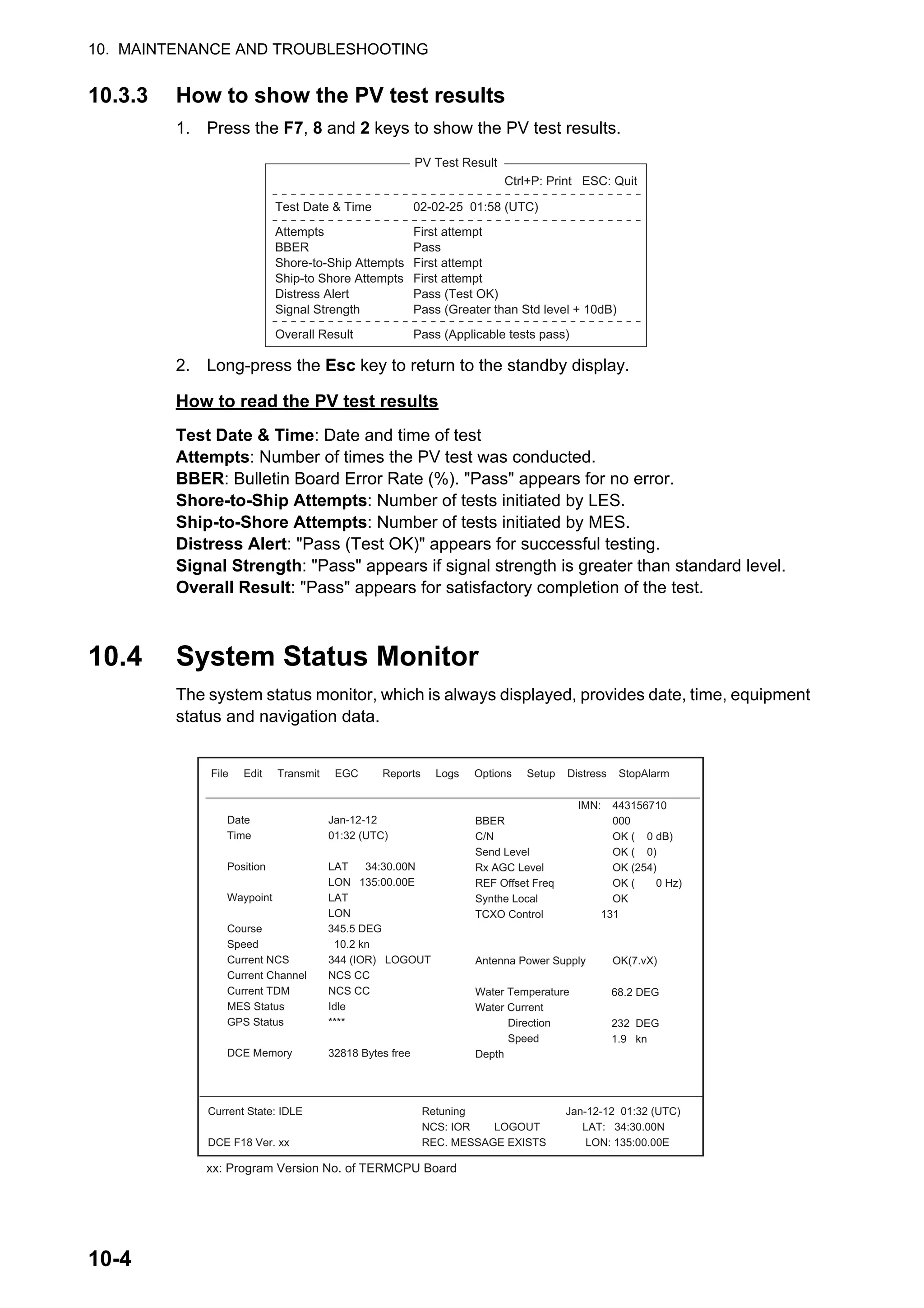
![10. MAINTENANCE AND TROUBLESHOOTING
10-5
How to read the system status monitor
Date: Current date.
Time: Current time.
Position: Own ship L/L position (either manual entry or automatic input by navigator).
Waypoint: L/L position of destination waypoint set on navigator.
Course: Course.
Speed: Ship’s speed.
Current NCS: NCS your vessel is logged in with.
Current Channel: Channel in use.
Current TDM: Channel TDM.
MES Status: Operational status of MES.
GPS Status: Receiving signal status from GPS receiver.
CST: Cold Start.
ACK: Acquired; Almanac data acquired.
IMP: Impossible; cannot receive GPS signal.
INT: Interrupted; object interfering with reception of GPS signal.
ALM: Receiving the almanac.
2D, 3D: Position-fixing method by 2D or 3D.
DCE Memory: Memory remaining in communication unit.
BBER: Bulletin Board Error Rate (%).
C/N: Check of circuit status with LES, receiving circuit in antenna unit and TERMCPU
Board in terminal unit. OK appears for figure greater than 31.
Send Level: TX level check. At transmission, OK appears for figure greater than 100.
At reception, OK appears for figure lower than 32.
RX AGC Level: Check of the receiving circuit of the antenna unit and the TERMCPU
Board in the terminal unit. OK appears for figure greater than 60.
REF Offset Freq: OK appears for figure lower than 150.
Synthe Local: Check of TERMCPU Board.
TCXO Control: Oscillator frequency control value.
Antenna Power Supply: NG appears for discontinuity or short in antenna cable. OK
is shown if the antenna is receiving electrical power.
Water Temperature*: Water temperature.
Water Current*
Direction: Tidal current direction.
Speed: Tidal current speed.
Depth*: Depth of water.
* Requires data from appropriate sensor.
10.5 Current Position Log
Position is saved to the [Current Position Log] every hour, and the log stores the latest
100 positions. When the log becomes full, the eldest entry is automatically deleted and
positions are renumbered.
To display the log, press the F7, 9 and 1 keys.](https://image.slidesharecdn.com/felcom-18ome56740a2-220309163554/75/Felcom-18-ome56740-a_2-127-2048.jpg)
![10. MAINTENANCE AND TROUBLESHOOTING
10-6
Current Position Log description
List: Put the highlight cursor here to put the cursor in the list then press the Enter key.
No.: The number of the position, in three digits.
Latitude, Longitude: Latitude and longitude of the position.
Op. Time(sec): The number of seconds the power has been on since the commission-
ing.
Date & Time(UTC): Date and time of the position.
Range: Specify the range of positions to show, with [From No.] and [To No.]. Put the
cursor on [From No.] (or [To No.]) then press the Enter key. Enter no. then press the
Enter key.
Total: Total no. of positions saved to the log.
[Ctrl]+[F]: Search: Search for specific position no.
[Ctrl]+[E]: Export: Export the position nos designated with [From No.] and [To No.],
to an SD card.
[Ctrl]+[P]: Print: Print the position nos designated with [From No.] and [To No.].
10.6 How to Replace the Fuse
The 15A fuse (for 12 VDC) or 7A fuse (for 24 VDC) in the power cable for the terminal
unit protects the system from overcurrent and reverse polarity. If the fuse blows, find
the cause before replacing it. If the fuse blows again after replacement, contact your
dealer for advice.
WARNING
Use the proper fuse.
Use of a wrong fuse can result in fire or damage
the equipment.
12 VDC
Code No.: 000-155-827-10
Type: FGBO 125V 15A PBF
24 VDC
Code No.: 000-155-831-10
Type: FGBO 125V 7A PBF
No. Latitude Longitude Op. Time(sec) Date & Time(UTC)
001 34:44.47N 135:21.29E 0000916673 JAN-21-12 17:46
002 35:21.29N 135:22.02E 0000913073 JAN-21-12 18:46
003
004
005
006
007
008
009
010
Current Position Log
Range: Total: 2
From No. To No.
[Ctrl]+[F]: Search
[Ctrl]+[E]: Export [Ctrl+[P]: Print
List](https://image.slidesharecdn.com/felcom-18ome56740a2-220309163554/75/Felcom-18-ome56740-a_2-128-2048.jpg)