Download to read offline

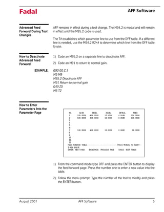
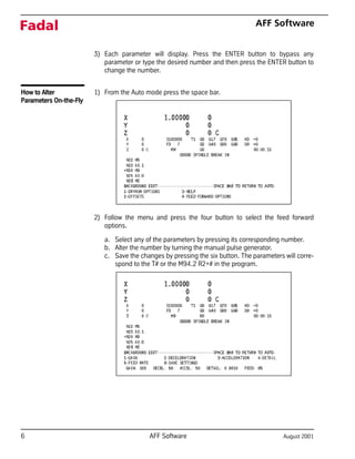


The document outlines the advanced feed forward (AFF) software for Fadal machines, designed to optimize high-speed machining by allowing users to adjust parameters such as gain, acceleration, deceleration, detail, and feed rate for enhanced performance. These parameters can be modified on-the-fly, coded into programs, or stored for use, improving cycle times and surface integrity. Recommendations for parameter settings during various machining stages (rough, semi-finish, and finish) are also provided to ensure efficient operation.


