Download to read offline

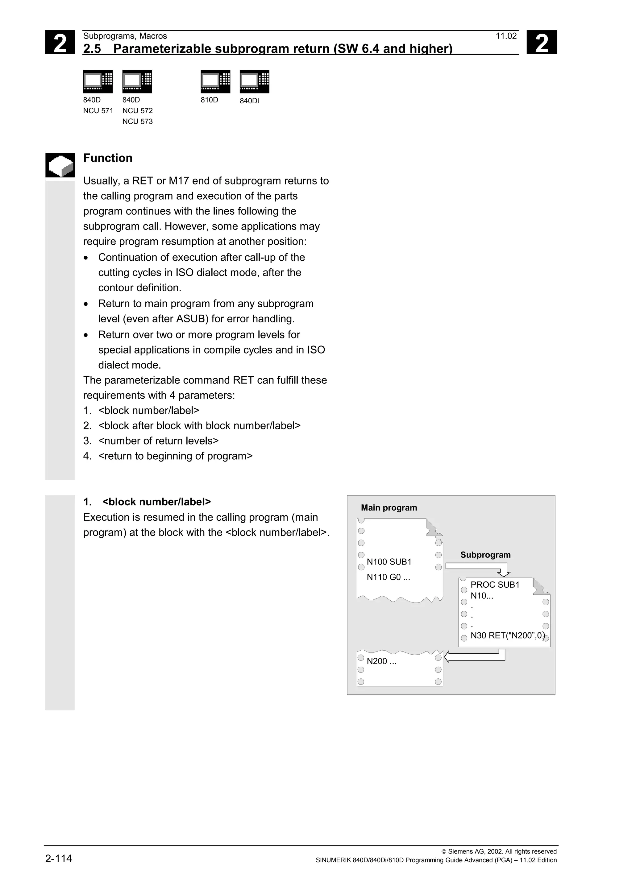
![© Siemens AG, 2002. All rights reserved
SINUMERIK 840D/840Di/810D Programming Guide Advanced (PGA) – 11.02 Edition 0-9
0
11.02 Contents
0
Motion-Synchronous Action 10-393
10.1 Structure, basic information ....................................................................................... 10-395
10.1.1 Programming and command elements................................................................ 10-397
10.1.2 Validity range: Identification number ID ............................................................... 10-398
10.1.3 Vocabulary word .................................................................................................. 10-399
10.1.4 Actions ................................................................................................................. 10-402
10.1.5 Overview of synchronized actions........................................................................ 10-404
10.2 Basic modules for conditions and actions.................................................................. 10-406
10.3 Special real-time variables for synchronized actions ................................................. 10-409
10.3.1 Flags/counters $AC_MARKER[n]........................................................................ 10-409
10.3.2 Timer variable $AC_TIMER[n], SW 4 and higher................................................ 10-409
10.3.3 Synchronized action parameters $AC_PARAM[n]............................................... 10-410
10.3.4 Access to R parameters $Rxx ............................................................................. 10-411
10.3.5 Machine and setting data read/write (SW 4 and higher)...................................... 10-412
10.3.6 FIFO variable $AC_FIFO1[n] … $AC_FIFO10[n] (SW 4 and higher).................. 10-413
10.4 Actions within synchronized actions........................................................................... 10-415
10.4.1 Auxiliary functions output ..................................................................................... 10-415
10.4.2 Set read-in disable RDISABLE ............................................................................ 10-416
10.4.3 Cancel preprocessing stop STOPREOF ............................................................. 10-417
10.4.4 Deletion of distance-to-go.................................................................................... 10-418
10.4.5 Delete distance-to-go with preparation, DELDTG, DELDTG ("Axis 1 to x") ........ 10-418
10.4.6 Polynomial definition, FCTDEF, block-synchronized ........................................... 10-420
10.4.7 Laser power control ............................................................................................. 10-422
10.4.8 Evaluation function SYNFCT ............................................................................... 10-423
10.4.9 Adaptive control (additive).................................................................................... 10-424
10.4.10 Adaptive control (multiplicative) ........................................................................... 10-425
10.4.11 Clearance control with limited compensation....................................................... 10-426
10.4.12 Online tool offset FTOC ....................................................................................... 10-428
10.4.13 Positioning movements........................................................................................ 10-430
10.4.14 Position axis POS ................................................................................................ 10-432
10.4.15 Start/stop axis MOV............................................................................................. 10-432
10.4.16 Axial feed FA........................................................................................................ 10-433
10.4.17 SW limit switch..................................................................................................... 10-434
10.4.18 Axis coordination.................................................................................................. 10-434
10.4.19 Set actual value.................................................................................................... 10-436
10.4.20 Spindle motions ................................................................................................... 10-437
10.4.21 Coupled-axis motion TRAILON, TRAILOF .......................................................... 10-438
10.4.22 Leading value coupling LEADON, LEADOF ........................................................ 10-439
10.4.23 Measurement....................................................................................................... 10-441
10.4.24 Set/clear wait marks: SETM, CLEARM (SW 5.2 and higher).............................. 10-441
10.4.25 Error responses ................................................................................................... 10-442
10.4.26 Travel to fixed stop FXS and FOCON/FOCOF.................................................... 10-442](https://image.slidesharecdn.com/fadaladvancedprogrammingmanual-220505063253/75/Fadal-Advanced-Programming-Manual-pdf-9-2048.jpg)
![1
11.02 Flexible NC Programming
1.1 Variable and arithmetic parameters 1
840D
NCU 571
840D
NCU 572
NCU 573
810D 840Di
Siemens AG, 2002. All rights reserved
SINUMERIK 840D/840Di/810D Programming Guide Advanced (PGA) – 11.02 Edition 1-27
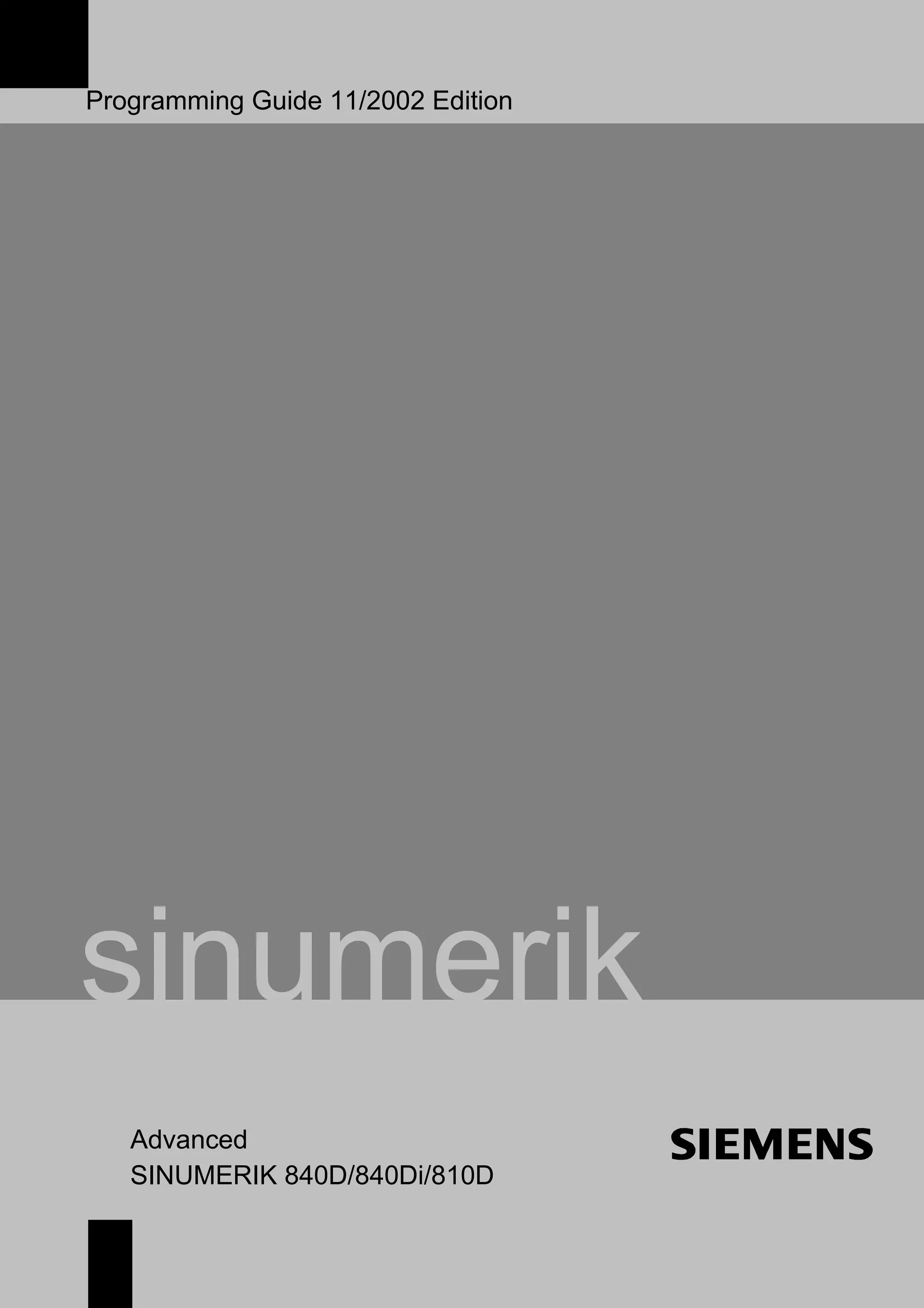
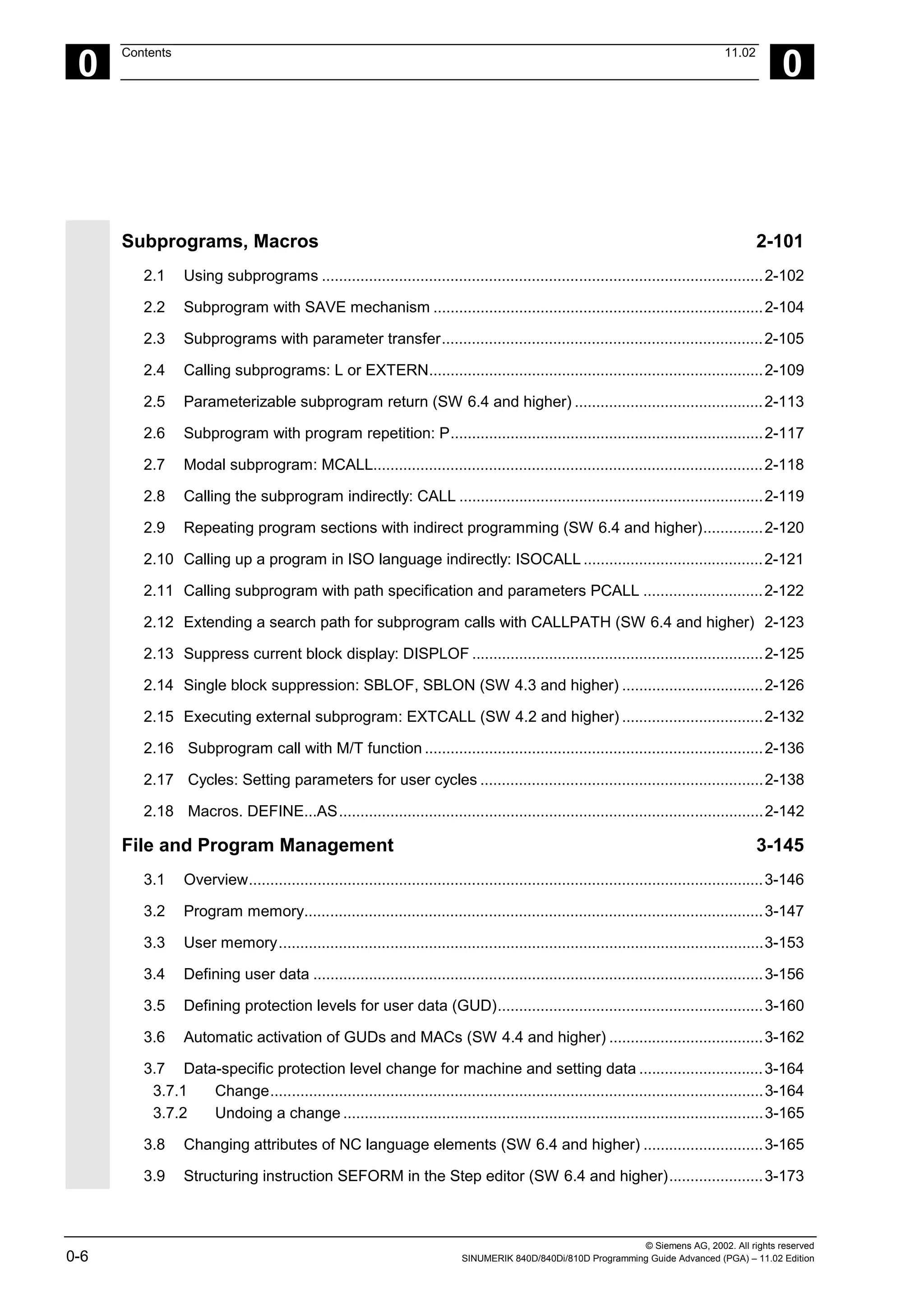
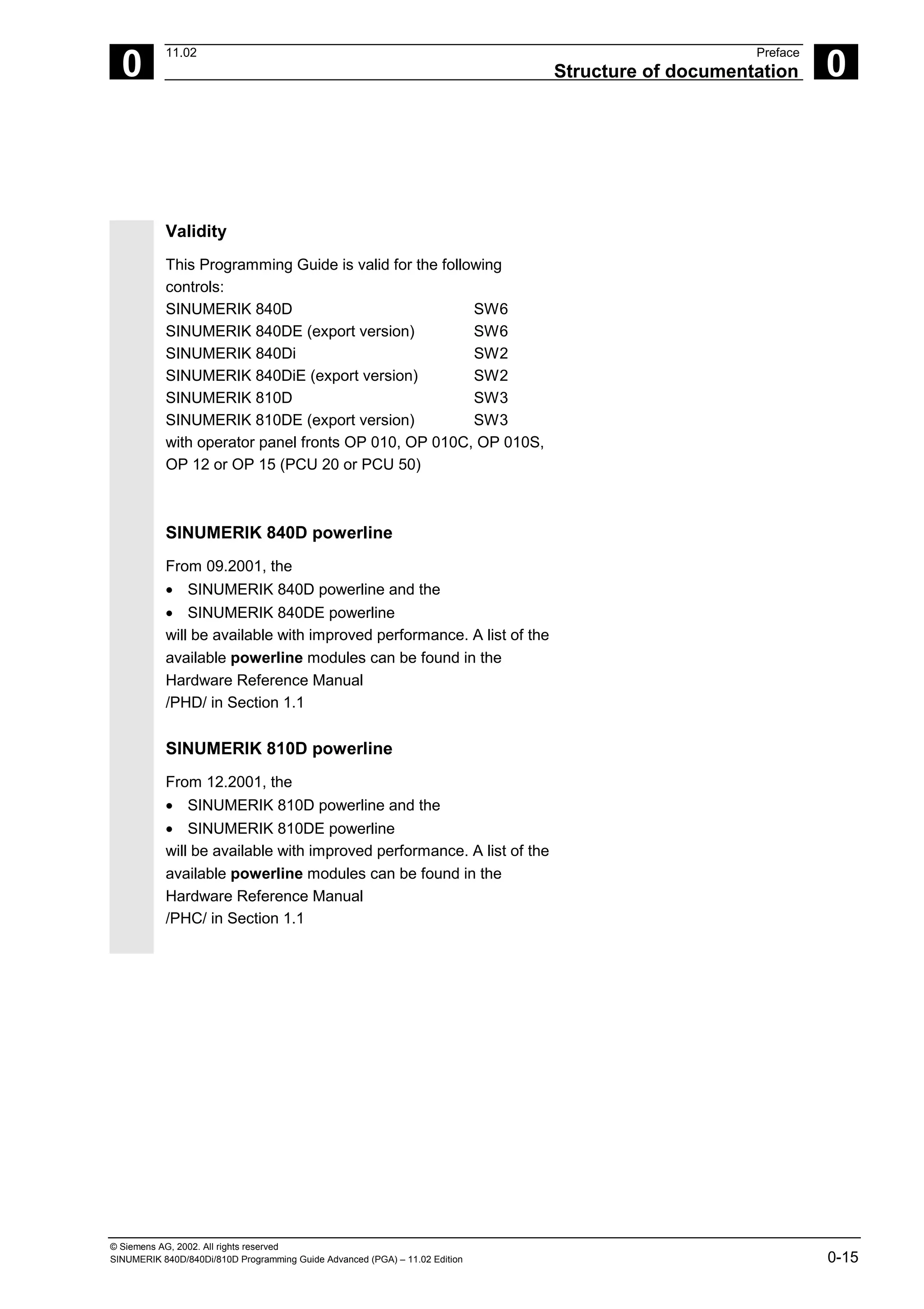
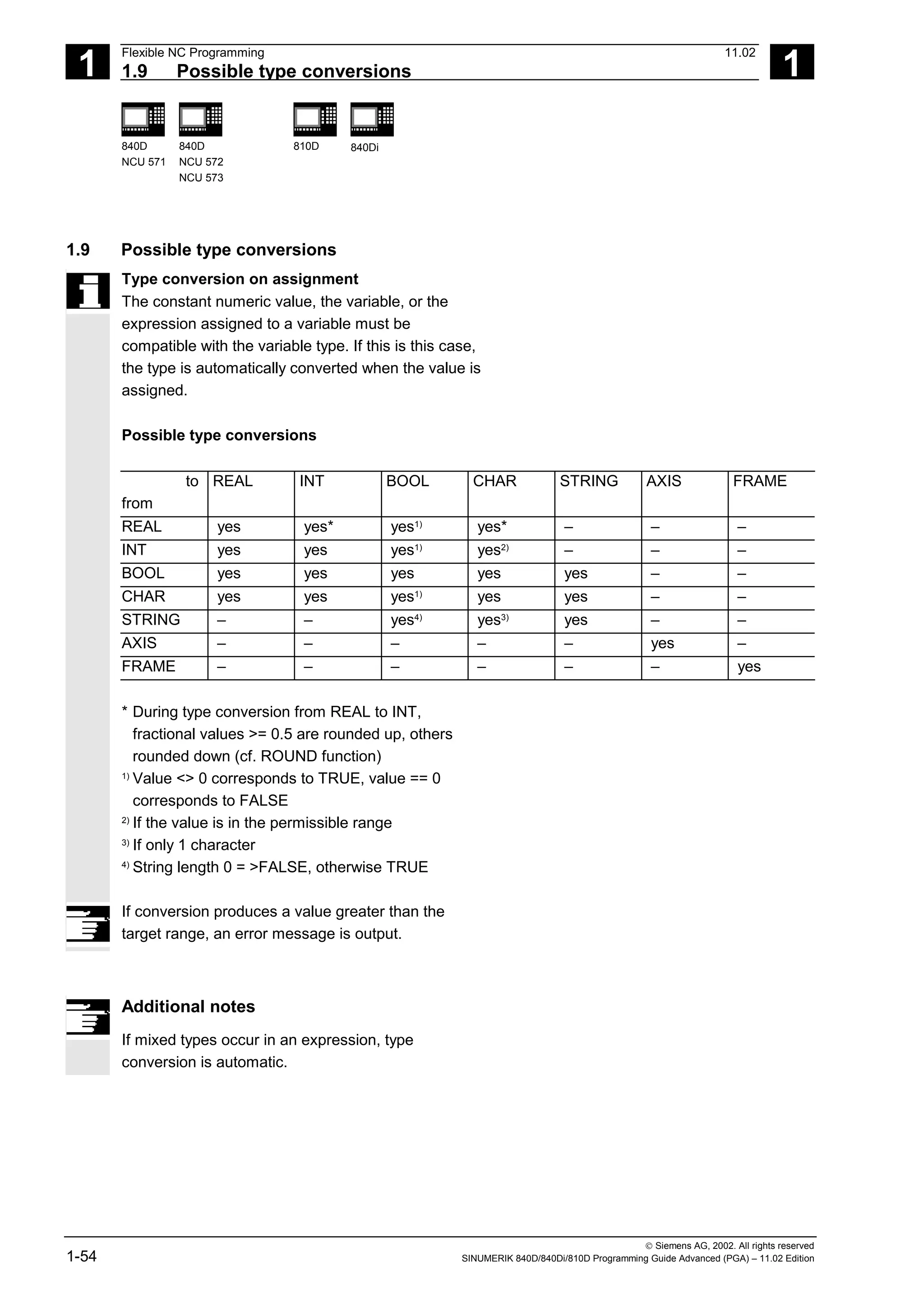
Variable types
Type Meaning Value range
INT Integers with sign ±(231
- 1)
REAL Real numbers (fractions with decimal point, LONG
REAL according to IEEE)
±(10-300
… 10+300
)
BOOL Boolean values: TRUE (1) and FALSE (0) 1, 0
CHAR 1 ASCII character specified by the code 0 … 255
STRING Character string, number of characters in […],
Max. 200 characters
Sequence of values
with 0 ... 255
AXIS Axis names (axis addresses) only All axis identifiers and
spindles in the channel
FRAME Geometric data for translation, rotation, scaling,
mirroring, see Chapter 4.
Arithmetic variable
Address R provides 100 arithmetic variables of type
REAL by default.
The exact number of arithmetic variables (up to
1000) is defined in machine data.
Example: R10=5
System variable
The controller provides system variables that can be
contained and processed in all running programs.
System variable provide machine and controller
states. Some of the system variables cannot be
assigned values.](https://image.slidesharecdn.com/fadaladvancedprogrammingmanual-220505063253/75/Fadal-Advanced-Programming-Manual-pdf-27-2048.jpg)
![1
Flexible NC Programming 11.02
1.2 Variable definition 1
840D
NCU 571
840D
NCU 572
NCU 573
810D 840Di
Siemens AG, 2002. All rights reserved
1-30 SINUMERIK 840D/840Di/810D Programming Guide Advanced (PGA) – 11.02 Edition
...
IF (VAR1==1) ;Read PUD
VAR1=VAR1+1 ;Read & write PUD
VAR2=1 ;Error: LUD from SUB2
;not known
ENDIF
...
M17
If machine data $MN_LUD_EXTENDED_SCOPE is set,
it is not possible to define a variable with the same
name in the main and subprograms.
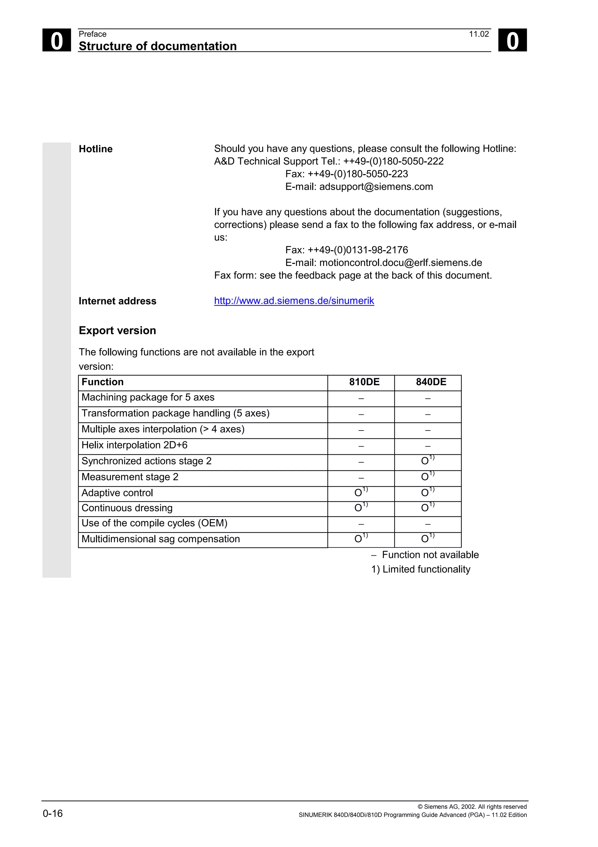
Variable names
A variable name consists of up to 31 characters. The
first two characters must be a letter or an underscore.
The "$" sign can not be used for user-defined
variables because it is used for system variables.
Programming
DEF INT name
or DEF INT name=value
DEF REAL name
or DEF REAL name1,name2=3,name4
or DEF REAL name[array_index1,array_index2]
DEF BOOL name
DEF CHAR name
or DEF CHAR name[array_index]=("A","B",…)
DEF STRING[string_length] name
DEF AXIS name
or DEF AXIS name[array_index]
DEF FRAME name](https://image.slidesharecdn.com/fadaladvancedprogrammingmanual-220505063253/75/Fadal-Advanced-Programming-Manual-pdf-30-2048.jpg)
![1
Flexible NC Programming 11.02
1.2 Variable definition 1
840D
NCU 571
840D
NCU 572
NCU 573
810D 840Di
Siemens AG, 2002. All rights reserved
1-32 SINUMERIK 840D/840Di/810D Programming Guide Advanced (PGA) – 11.02 Edition
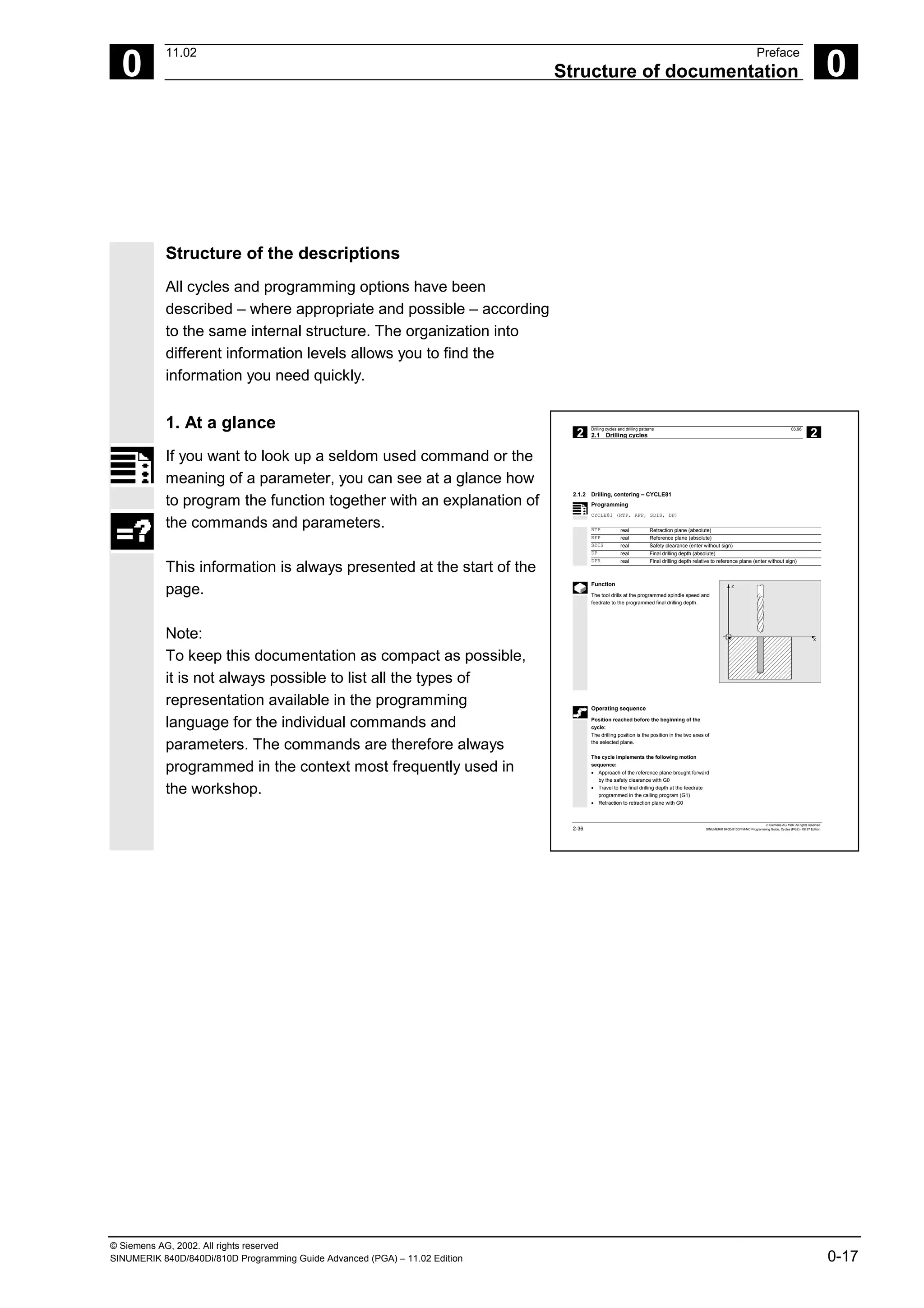
Variable type BOOL
DEF BOOL IF_TOO_MUCH This creates a variable of type BOOL with
the name IF_TOO_MUCH.
System initializes with zero (FALSE).
DEF BOOL IF_TOO_MUCH=1 or
DEF BOOL IF_TOO_MUCH=TRUE or
DEF BOOL WENN_ZUVIEL=FALSE
This creates a variable of type BOOL with
the name IF_TOO_MUCH.
Variable type CHAR
DEF CHAR GUSTAV_1=65 A code value for the corresponding ASCII
character or the ASCII character itself
DEF CHAR GUSTAV_1="A" can be assigned to a variable of type CHAR
(code value 65 corresponds to letter "A").
Variable type STRING
DEF STRING[6] MUSTER_1="BEGIN" Variables of type string can contain a string
(sequence of characters). The maximum
number of characters is enclosed in square
brackets after the variable type.
Variable type AXIS
DEF AXIS AXIS_NAME=(X1) Variable of type AXIS are called
AXIS_NAME and contain the axis identifier
of a channel – here X1. (Axis names with an
extended address are in parentheses.)
Variable type FRAME
DEF FRAME BEVEL_1 Variables of type FRAME have names like
BEVEL_1.](https://image.slidesharecdn.com/fadaladvancedprogrammingmanual-220505063253/75/Fadal-Advanced-Programming-Manual-pdf-32-2048.jpg)
![1
11.02 Flexible NC Programming
1.2 Variable definition 1
840D
NCU 571
840D
NCU 572
NCU 573
810D 840Di
Siemens AG, 2002. All rights reserved
SINUMERIK 840D/840Di/810D Programming Guide Advanced (PGA) – 11.02 Edition 1-33
Additional notes
A variable of type AXIS can contain an axis identifier
and a spindle identifier of a channel.
Note:
Axis names with an extended address must be in
parentheses.
Example of programming with program-
local variables
DEF INT COUNT
LOOP: G0 X… ;Loop
COUNT=COUNT+1
IF COUNT<50 GOTOB LOOP
M30
Programming example
Query of existing geometry axes
DEF AXIS ABSCISSA; ;1. geometry axis
IF ISAXIS(1) == FALSE GOTOF CONTINUE
ABSCISSA = $P_AXN1
…
CONTINUE:
Indirect spindle programming
DEF AXIS SPINDLE
SPINDLE=(S1)
OVRA[SPINDLE]=80 ;Spindle override = 80%
SPINDLE=(S3)
…](https://image.slidesharecdn.com/fadaladvancedprogrammingmanual-220505063253/75/Fadal-Advanced-Programming-Manual-pdf-33-2048.jpg)
![1
Flexible NC Programming 11.02
1.3 Array definition 1
840D
NCU 571
840D
NCU 572
NCU 573
810D 840Di
Siemens AG, 2002. All rights reserved
1-34 SINUMERIK 840D/840Di/810D Programming Guide Advanced (PGA) – 11.02 Edition
1.3 Array definition
Programming
DEF CHAR NAME[n,m]
DEF INT NAME[n,m]
DEF REAL NAME[n,m]
DEF AXIS NAME[n,m]
DEF FRAME NAME[n,m]
DEF STRING[string_length] NAME[m]
DEF BOOL[n,m]
Explanation
INT NAME[n,m]
REAL NAME[n,m]
Variable type (CHAR, INTEGER, REAL,
AXIS, FRAME, BOOL)
n = array size for 1st dimension
m = array size for 2nd dimension
DEF STRING[string_length] NAME[m] Data type STRING can only be defined for
1-dimensional arrays
NAME Variable name
The same memory size applies to type BOOL as to
type CHAR.
Up to SW3:
The maximum size of an array is set via machine data.
Machine manufacturer
See machine manufacturer's specifications
Type Memory requirement per array element
BOOL 1 byte
CHAR 1 byte
INT 4 bytes
REAL 8 bytes
STRING String length + 1
FRAME ∼ 400 bytes, depending on number of axes
AXIS 4 bytes
The maximum array size determines the size of the
memory blocks in which the variable memory is
managed. It should not be set higher than actually
required.
Standard: 812 bytes
If not large arrays are defined, select: 256 bytes.](https://image.slidesharecdn.com/fadaladvancedprogrammingmanual-220505063253/75/Fadal-Advanced-Programming-Manual-pdf-34-2048.jpg)
![1
11.02 Flexible NC Programming
1.3 Array definition 1
840D
NCU 571
840D
NCU 572
NCU 573
810D 840Di
Siemens AG, 2002. All rights reserved
SINUMERIK 840D/840Di/810D Programming Guide Advanced (PGA) – 11.02 Edition 1-35
SW 4 and higher:
An array can be larger than a memory block. The
MD value for block size should be set such that
arrays are fragmented only in exceptional cases.
Default: 256 bytes
Memory requirement per element: see above
Example:
Global user data must contain PLC machine data for
switching the controller on/off (definition of BOOL arrays).
Additional notes
Arrays with up to 2 dimensions can be defined.
Arrays with variables of type STRING can only be
1-dimensional. The string length is specified after the
data type String.
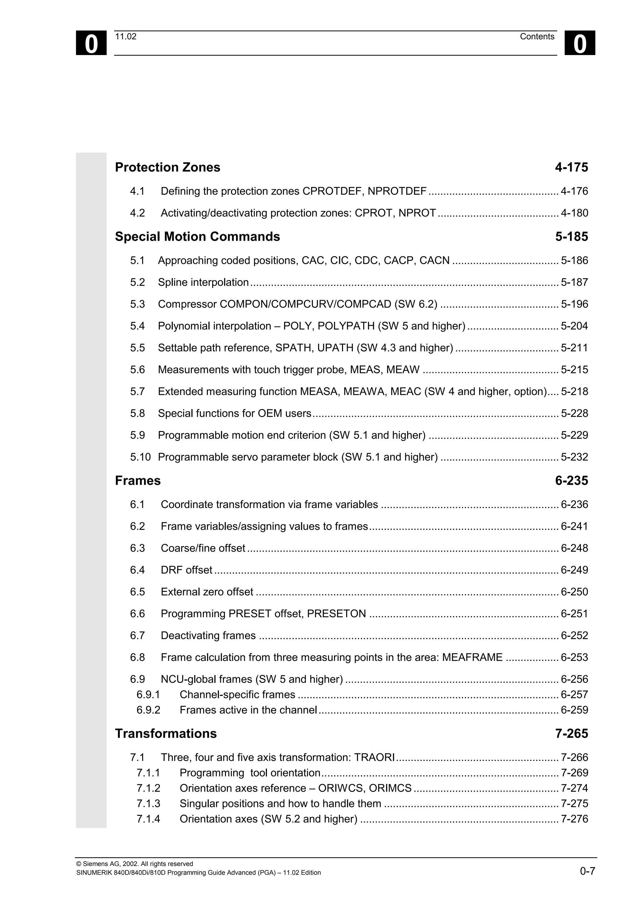
Array index
Elements of an array are accessed via the array
index. The array elements can either be read or
assigned values using this array index.
The first array element starts with index [0,0]; for
example, for array size [3,4] the maximum possible
array index is [2,3].
. . . . .
. . . . .
. . . . .
0,m-1
0.2
0.1
0.0
. . . . .
1,m-1
1.2
1.1
1.0
. . . . .
n- ,m-1
1,
n-1.2
n-1.1
n-1.0
[n,m]
n
m
Array index
. . . . .](https://image.slidesharecdn.com/fadaladvancedprogrammingmanual-220505063253/75/Fadal-Advanced-Programming-Manual-pdf-35-2048.jpg)
![1
Flexible NC Programming 11.02
1.3 Array definition 1
840D
NCU 571
840D
NCU 572
NCU 573
810D 840Di
Siemens AG, 2002. All rights reserved
1-36 SINUMERIK 840D/840Di/810D Programming Guide Advanced (PGA) – 11.02 Edition
In the above example, the values have been
initialized to double as the index of the array
element. in order to illustrate the sequence of the
individual array elements.
Initialization of arrays
The array elements can be initialized during program
run or in the array definition.
In 2-dimensional arrays, the right array index is
increment first.
Initialization with value lists, SET
1. Initializing in the array definition
DEF Type VARIABLE = SET(VALUE)
DEF Type ARRAY[n,m] = SET(VALUE, value, …)
Or:
DEF Type VARIABLE = Value
DEF Type ARRAY[n,m] = (value, value, …)
• As many array elements are assigned as
initialization values are programmed.
• Array elements without values (gaps in the value
list) are automatically initialized to 0.
• For variables of type AXIS, gaps in the value list
are not permitted.
• Programming more values than exist in the
remaining array elements triggers an alarm.
Example:
DEF REAL ARRAY[2,3]=(10, 20, 30, 40)
SET is optional in the array definition.](https://image.slidesharecdn.com/fadaladvancedprogrammingmanual-220505063253/75/Fadal-Advanced-Programming-Manual-pdf-36-2048.jpg)
![1
11.02 Flexible NC Programming
1.3 Array definition 1
840D
NCU 571
840D
NCU 572
NCU 573
810D 840Di
Siemens AG, 2002. All rights reserved
SINUMERIK 840D/840Di/810D Programming Guide Advanced (PGA) – 11.02 Edition 1-37
2. Initializing during the program run
ARRAY[n,m]= SET(value, value, value,…)
ARRAY[n,m]= SET(expression,
expression, expression,…)
• Initialization is the same as in array definition.
• Expressions are possible values in this case too.
• Initialization starts at the programmed array
indexes. Values can also be assigned selectively
to subarrays.
Example:
Assignment of expressions
DEF INT ARRAY[5, 5]
ARRAY[0,0] = SET(1, 2, 3, 4, 5)
ARRAY[2,3] = SET(VARIABLE, 4*5.6)
The axis index of axis variables is not traversed:
Example:
Initialization in one line
$MA_AX_VELO_LIMIT[1, AX1] = SET(1.1, 2.2, 3.3)
Is equivalent to:
$MA_AX_VELO_LIMIT[1,AX1] = 1.1
$MA_AX_VELO_LIMIT[2,AX1] = 2.2
$MA_AX_VELO_LIMIT[3,AX1] = 3.3](https://image.slidesharecdn.com/fadaladvancedprogrammingmanual-220505063253/75/Fadal-Advanced-Programming-Manual-pdf-37-2048.jpg)
![1
Flexible NC Programming 11.02
1.3 Array definition 1
840D
NCU 571
840D
NCU 572
NCU 573
810D 840Di
Siemens AG, 2002. All rights reserved
1-38 SINUMERIK 840D/840Di/810D Programming Guide Advanced (PGA) – 11.02 Edition
Initialization with the same values, REP
1. Initializing in the array definition
DEF Type ARRAY[n,m] = REP(value)
All array elements are assigned the same value
(constant).
Variables of type FRAME cannot be initialized.
Example:
DEF REAL ARRAY5[10,3] = REP(9.9)
2. Initializing during the program run
ARRAY[n,m] = REP(value)
ARRAY[n,m] = REP(expression)
• Expressions are possible values in this case too.
• All array elements are initialized to the same
value.
• Initialization starts at the programmed array
indexes. Values can also be assigned selectively
to subarrays.
Variables of type FRAME are permissible and can
initialized very simply in this way.
Example:
Initialization of all elements with one value
DEF FRAME FRM[10]
FRM[5] = REP(CTRANS (X,5))](https://image.slidesharecdn.com/fadaladvancedprogrammingmanual-220505063253/75/Fadal-Advanced-Programming-Manual-pdf-38-2048.jpg)
![1
11.02 Flexible NC Programming
1.3 Array definition 1
840D
NCU 571
840D
NCU 572
NCU 573
810D 840Di
Siemens AG, 2002. All rights reserved
SINUMERIK 840D/840Di/810D Programming Guide Advanced (PGA) – 11.02 Edition 1-39
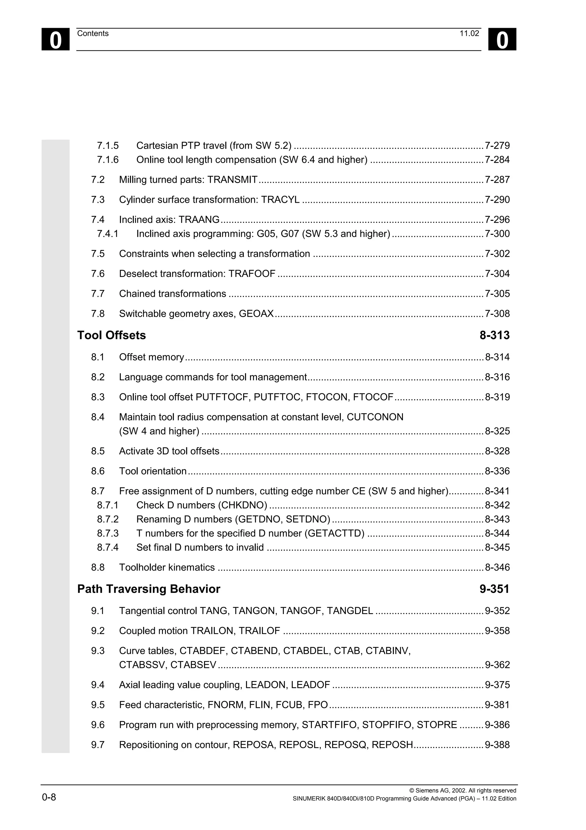
Programming example
Initialization of complete variable arrays.
The current assignment is shown in the drawing.
N10 DEF REAL FELD1[10,3] = SET(0, 0, 0, 10, 11, 12, 20, 20, 20, 30, 30,
30, 40, 40, 40,)
N20 FELD1[0,0] = REP(100)
N30 FELD1[5,0] = REP(-100)
N40 FELD1[0,0] = SET(0, 1, 2, -10, -11, -12, -20, -20, -20, -30, , , ,
-40, -40, -50, -60, -70)
N50 FELD1[8,1] = SET(8.1, 8.2, 9.0, 9.1, 9.2)
0
1
2
3
4
5
6
7
8
9
0
0
10
20
30
40
0
0
0
0
0
1
0
11
20
30
40
0
0
0
0
0
2
0
12
20
30
40
0
0
0
0
0
0
100
100
100
100
100
–100
–100
–100
–100
–100
1
100
100
100
100
100
–100
–100
–100
–100
–100
2
100
100
100
100
100
–100
–100
–100
–100
–100
0
0
–10
–20
–30
0
–50
–100
–100
–100
9.0
1
1
–11
–20
0
–40
–60
–100
–100
8.1
9.1
2
2
–12
–20
0
–40
–70
–100
–100
8.2
9.2
1.2
N10: Initialization
with definition
N20/N30: Initialization
with identical value
N40/N50: Initialization
with different values
The array elements [5.0]
to [9.2] have been initialized
with the default value (0.0).
The array elements [3.1]
to [4.0] have been initialized
with the default value (0.0).
The array elements [6.0] to
[8.0] have not been changed.
1
2
Array index](https://image.slidesharecdn.com/fadaladvancedprogrammingmanual-220505063253/75/Fadal-Advanced-Programming-Manual-pdf-39-2048.jpg)
![1
Flexible NC Programming 11.02
1.4 Indirect programming 1
840D
NCU 571
840D
NCU 572
NCU 573
810D 840Di
Siemens AG, 2002. All rights reserved
1-40 SINUMERIK 840D/840Di/810D Programming Guide Advanced (PGA) – 11.02 Edition
1.4 Indirect programming
Indirect programming permits general-purpose use
of programs. The extended address (index) is
substituted by a variable of suitable type.
All addresses are parameterizable except:
• N – Block number
• G – G command
• L – Subprogram
Indirect programming is not possible for settable
addresses.
Example: X[1] in place of X1 is not permissible.
Programming
ADDRESS[INDEX]
Programming examples
Spindle
S1=300 Direct programming
DEF INT SPINU=1
S[SPINU]=300
Indirect programming:
Speed 300rpm for the spindle whose
number is stored in the SPINU variable (in
this example 1).
Feed
FA[U]=300 Direct programming
DEF AXIS AXVAR2=U
FA[AXVAR2]=300
Indirect programming:
Feedrate for positioning axis whose address
name is stored in the variable of type AXIS
with the variable name AXVAR2.
Measured value
$AA_MM[X] Direct programming
DEF AXIS AXVAR3=X
$AA_MM[AXVAR3]
Indirect programming:
Measured value in machine coordinates for
the axis whose name is stored in variable
AXVAR3.](https://image.slidesharecdn.com/fadaladvancedprogrammingmanual-220505063253/75/Fadal-Advanced-Programming-Manual-pdf-40-2048.jpg)
![1
11.02 Flexible NC Programming
1.4 Indirect programming 1
840D
NCU 571
840D
NCU 572
NCU 573
810D 840Di
Siemens AG, 2002. All rights reserved
SINUMERIK 840D/840Di/810D Programming Guide Advanced (PGA) – 11.02 Edition 1-41
Array element
DEF INT FELD1[4,5] Direct programming
DEFINE DIM1 AS 4
DEFINE DIM2 AS 5
DEF INT ARRAY[DIM1,DIM2]
ARRAY[DIM1-1,DIM2-1]=5 Indirect programming:
Array dimensions must be stated as
constant values.
Axis assignment with axis variables
X1=100 X2=200 Direct programming
DEF AXIS AXVAR1 AXVAR2
AXVAR1=(X1) AXVAR2=(X2)
AX[AXVAR1]=100 AX[AXVAR2]=200
Indirect programming:
Definition of the variables
Assignment of the axis names, traversal of
axes that are stored in the variables to 100
or 200.
Interpolation parameters with axis variables
G2 X100 I20 Direct programming
DEF AXIS AXVAR1=X
G2 X100 IP[AXVAR1]=20
Indirect programming:
Definition and assignment of the axis name
Indirect programming of the center
Indirect subprogram call
CALL "L" << R10 Call of the program whose number is in R10
Additional notes
R parameters can also be considered 1-dimensional
arrays with abbreviated notation (R10 is equivalent
to R[10]).](https://image.slidesharecdn.com/fadaladvancedprogrammingmanual-220505063253/75/Fadal-Advanced-Programming-Manual-pdf-41-2048.jpg)
![1
Flexible NC Programming 11.02
1.4 Indirect programming 1
840D
NCU 571
840D
NCU 572
NCU 573
810D 840Di
Siemens AG, 2002. All rights reserved
1-42 SINUMERIK 840D/840Di/810D Programming Guide Advanced (PGA) – 11.02 Edition
Indirect G code programming from SW 5
G[<Group index>] = <integer/real variable>
Indirect programming of G codes using variables for effective cycle programming
Meaning of the parameters
<Goup index> Integer constants with which the G code group is selected.
<integer/real variable> Variable of the integer or real type with which the G code number is
selected.
Function
Indirect G code programming (SW 5 and higher)
The indirect programming of G codes using
variables facilitates effective cycle programming.
Two parameters
• G code groups integer constant
• G code numbers variable of the integer/real type
are available for this.
Valid G code groups
Only modal G code groups can be programmed
indirectly.
Non-modal G code groups are rejected by alarm
12470.
Valid G code numbers
Arithmetic functions are not legal in indirect G code
programming.
The G code number must be stored in a variable of
the integer or real type. Invalid G code numbers are
rejected by alarm 12475.
If it is necessary to calculate the G code number,
this must be done in a separate parts program line
before the indirect G code programming.
Additional notes
All the valid G codes are shown in the PG, in the
"List of G functions/preparatory functions" section in
various groups.
See /PG/ Fundamentals Programming Guide, "Tables"](https://image.slidesharecdn.com/fadaladvancedprogrammingmanual-220505063253/75/Fadal-Advanced-Programming-Manual-pdf-42-2048.jpg)
![1
11.02 Flexible NC Programming
1.4 Indirect programming 1
840D
NCU 571
840D
NCU 572
NCU 573
810D 840Di
Siemens AG, 2002. All rights reserved
SINUMERIK 840D/840Di/810D Programming Guide Advanced (PGA) – 11.02 Edition 1-43
Programming example
Indirect G code programming
; Settable zero offset G code group 8
N1010 DEF INT INT_VAR
N1020 INT_VAR = 2
...
N1090 G[8] = INT_VAR G1 X0 Y0 ; G54
N1100 INT_VAR = INT_VAR + 1 ; G code calculation
N1110 G[8] = INT_VAR G1 X0 Y0 ; G55
; Plane selection G code group 6
N2010 R10 = $P_GG[6] ; Read G code for current plane
...
N2090 G[6] = R10 ; G17 – G19](https://image.slidesharecdn.com/fadaladvancedprogrammingmanual-220505063253/75/Fadal-Advanced-Programming-Manual-pdf-43-2048.jpg)
![1
Flexible NC Programming 11.02
1.4 Indirect programming 1
840D
NCU 571
840D
NCU 572
NCU 573
810D 840Di
Siemens AG, 2002. All rights reserved
1-44 SINUMERIK 840D/840Di/810D Programming Guide Advanced (PGA) – 11.02 Edition
Run string as parts program line
EXECSTRING (<string variable>)
Command EXECSTRING runs a parts program line indirectly
Meaning of the parameters
<string variable> Parameter of type string is transferred with EXECSTRING
Function
EXECSTRING (from SW 6.4)
Parts program command EXECSTRING transfers a
string as a parameter that already contains the parts
program line to run.
Additional notes
All parts program constructions that can be
programmed in a parts program can be output. That
excludes PROC and DEF instructions and all use of INI
and DEF files.
Programming example
Indirect parts program line
N100 DEF STRING[100] BLOCK String variable to be included in parts
program line
N110 DEF STRING[10] MFCT1 = "M7"
N200 EXECSTRING(MFCT1 << " M4711") Run parts program line "M7 M4711"
N300 R10 = 1
N310 BLOCK = "M3"
N320 IF(R10)
N330 BLOCK = BLOCK << MFCT1
N340 ENDIF
N350 EXECSTRING(BLOCK) Run parts program line "M3 M4711"](https://image.slidesharecdn.com/fadaladvancedprogrammingmanual-220505063253/75/Fadal-Advanced-Programming-Manual-pdf-44-2048.jpg)
![1
11.02 Flexible NC Programming
1.7 Comparison and logic operators 1
840D
NCU 571
840D
NCU 572
NCU 573
810D 840Di
Siemens AG, 2002. All rights reserved
SINUMERIK 840D/840Di/810D Programming Guide Advanced (PGA) – 11.02 Edition 1-51
Logic operators
Logic operators are used to link truth values.
AND, OR, NOT, and XOR can only be applied to
variables of type BOOL. However, they can also be
applied to data types CHAR, INT, and REAL by
implicit type conversion.
Spaces must be left between BOOLEAN operands
and operators.
For the logic (Boolean) operations, the following
applies to data types BOOL, CHAR, INT, and REAL:
0 means FALSE
not equal to 0 means TRUE
Meaning of logic operators
AND AND
OR OR
NOT Negation
XOR Exclusive OR
In arithmetic expressions, the execution order of all
the operators can be specified by parentheses, in
order to override the normal priority rules.
Programming example
IF (R10<50) AND ($AA_IM[X]>=17.5) GOTOF ZIEL
IF NOT R10 GOTOB START
NOT is only applied to one operand.](https://image.slidesharecdn.com/fadaladvancedprogrammingmanual-220505063253/75/Fadal-Advanced-Programming-Manual-pdf-51-2048.jpg)
![1
11.02 Flexible NC Programming
1.10 String operations 1
840D
NCU 571
840D
NCU 572
NCU 573
810D 840Di
Siemens AG, 2002. All rights reserved
SINUMERIK 840D/840Di/810D Programming Guide Advanced (PGA) – 11.02 Edition 1-55
1.10 String operations
Overview
Further string manipulations are provided in addition to the
conventional operations "Assignment" and "Comparison"
described in this section:
Explanation
Type conversion to STRING:
STRING_ERG = <<bel._Typ1)
Result type: STRING
STRING_ERG = AXSTRING (AXIS) Result type: STRING
Type conversion from STRING:
BOOL_ERG = ISNUMBER (STRING) Result type: BOOL
REAL_ERG = NUMBER (STRING) Result type: REAL
AXIS_ERG = AXNAME (STRING) Result type: AXIS
Concatenation of strings:
bel._Typ1)
<< bel. Typ1)
Result type: STRING
Conversion to lower/upper case:
STRING_ERG = TOUPPER (STRING) Result type: STRING
STRING_ERG = TOLOWER (STRING) Result type: STRING
Length of the string:
INT_ERG = STRLEN (STRING) Result type: INT
Look for character/string in the string:
INT_ERG = INDEX (STRING, CHAR) Result type: INT
INT_ERG = RINDEX (STRING, CHAR) Result type: INT
INT_ERG = MINDEX (STRING, STRING) Result type: INT
INT_ERG = MATCH (STRING, STRING) Result type: INT
Selection of a substring:
STRING_ERG = SUBSTR (STRING, INT) Result type: INT
STRING_ERG = SUBSTR (STRING, INT, INT) Result type: INT
Selection of a single character:
CHAR_ERG = STRINGVAR [IDX] Result type: CHAR
CHAR_ERG = STRINGFELD [IDX_FELD, IDX_CHAR] Result type: CHAR
1)
"bel._Typ" stands for variable types INT, REAL, CHAR, STRING, and BOOL.](https://image.slidesharecdn.com/fadaladvancedprogrammingmanual-220505063253/75/Fadal-Advanced-Programming-Manual-pdf-55-2048.jpg)
![1
Flexible NC Programming 11.02
1.10 String operations 1
840D
NCU 571
840D
NCU 572
NCU 573
810D 840Di
Siemens AG, 2002. All rights reserved
1-56 SINUMERIK 840D/840Di/810D Programming Guide Advanced (PGA) – 11.02 Edition
Special meaning of the 0 char
The 0 char is interpreted internally end-of-string.
Replacing a character by the 0 character truncates
the string.
Example:
DEF STRING[20] STRG = "Axis . stopped"
STRG[6] = "X" ;Returns the message "Axis X
stopped"
MSG(STRG)
STRG[6] = 0
MSG(STRG) ;Returns the message "Axis"
1.10.1 Type conversion
This enables use of variables of different types in a
message (MSG).
Conversion to STRING
Performed implicitly with use of the operator << for
data types INT, REAL, CHAR, and BOOL (see
"Concatenation of strings").
An INT value is converted to normal readable
format. REAL values convert with up to 10 decimal
places.
Variables of type AXIS can be converted to STRING
by the AXSTRING function.
FRAME variables cannot be converted.
Example:
MSG("Position:"<<$AA_IM[X])](https://image.slidesharecdn.com/fadaladvancedprogrammingmanual-220505063253/75/Fadal-Advanced-Programming-Manual-pdf-56-2048.jpg)
![1
11.02 Flexible NC Programming
1.10 String operations 1
840D
NCU 571
840D
NCU 572
NCU 573
810D 840Di
Siemens AG, 2002. All rights reserved
SINUMERIK 840D/840Di/810D Programming Guide Advanced (PGA) – 11.02 Edition 1-57
Conversion from STRING
The NUMBER function converts from STRING to
REAL.
If ISNUMBER returns the value FALSE, CALLING
NUMBER with the same parameter will trigger an
alarm.
The AXNAME function converts a string to data type
AXIS. An alarm is output if the string cannot be
assigned to any configured axis identifier.
Syntax
BOOL_ERG = ISNUMBER (STRING) Result type: BOOL
REAL_ERG = NUMBER (STRING) Result type: REAL
STRING_ERG = AXSTRING (AXIS) Result type: STRING
AXIS_ERG = AXNAME (STRING) Result type: AXIS
Semantics:
ISNUMBER (STRING) returns TRUE, if the string is a
valid REAL by the rules of the language. It is thus
possible to check whether the string can be converted
to a valid number.
NUMBER (STRING) returns the number represented
by the string as a REAL.
AXSTRING (AXIS) returns the specified axis identifier
as a string.
AXNAME (STRING) converts the string specified to
an axis identifier.
Examples
DEF BOOL BOOL_ERG
DEF REAL REAL_ERG
DEF AXIS AXIS_ERG
DEF STRING[32] STRING_ERG
BOOL_ERG = ISNUMBER ("1234.9876Ex-7") ;Now: BOOL_ERG == TRUE
BOOL_ERG = ISNUMBER ("1234XYZ") ;Now: BOOL_ERG == FALSE
REAL_ERG = NUMBER ("1234.9876Ex-7") ;Now: REAL_ERG == 1234.9876Ex-7
STRING_ERG = AXSTRING(X) ;Now: STRING_ERG == "X"
AXIS_ERG = AXNAME("X") ;Now: AXIS_ERG == X](https://image.slidesharecdn.com/fadaladvancedprogrammingmanual-220505063253/75/Fadal-Advanced-Programming-Manual-pdf-57-2048.jpg)
![1
Flexible NC Programming 11.02
1.10 String operations 1
840D
NCU 571
840D
NCU 572
NCU 573
810D 840Di
Siemens AG, 2002. All rights reserved
1-58 SINUMERIK 840D/840Di/810D Programming Guide Advanced (PGA) – 11.02 Edition
1.10.2 Concatenation of strings
This functionality puts a string together out of
separate components. The chaining function is
implemented via operator: <<. This operator has
STRING as the target type for all combinations of
basic types CHAR, BOOL, INT, REAL and STRING.
Any conversion that may be required is carried out
according to existing rules. Types FRAME and AXIS
cannot be used with this operator.
Syntax:
bel._Typ << bel._Typ Result type: STRING
Semantics:
The strings specified (possibly implicitly converted
non-string types) are concatenated.
This operator can also be used as a "unary" operator
with a single operand. This can be used for explicit
type conversion to STRING (not for FRAME and
AXIS).
Syntax:
<< bel._Typ Result type: STRING
Semantics:
The specified type is implicitly converted to STRING
type.
This can be used to put together a message or a
command out of text lists and insert parameters into
it (e.g. a module name):
MSG(STRG_TAB[LOAD_IDX]<<MODULE_NAME)](https://image.slidesharecdn.com/fadaladvancedprogrammingmanual-220505063253/75/Fadal-Advanced-Programming-Manual-pdf-58-2048.jpg)
![1
11.02 Flexible NC Programming
1.10 String operations 1
840D
NCU 571
840D
NCU 572
NCU 573
810D 840Di
Siemens AG, 2002. All rights reserved
SINUMERIK 840D/840Di/810D Programming Guide Advanced (PGA) – 11.02 Edition 1-59
The intermediate results of string concatenation
must not exceed the maximum string length.
Programming examples
DEF INT IDX = 2
DEF REAL VALUE = 9.654
DEF STRING[20]STRG = "INDEX:2"
IF STRG == "Index:" <<IDX GOTOF NO_MSG
MSG ("Index:" <<IDX <<"/Value:"
<<VALUE)
;Display: "Index: 2/value: 9.654"
NO_MSG:
1.10.3 Conversion to lower/upper case
This functionality permits conversion of all letters of
a string to standard capitalization.
Syntax:
STRING_ERG = TOUPPER (STRING) Result type: STRING
STRING_ERG = TOLOWER (STRING) Result type: STRING
Semantics:
All lower case letters are converted to either upper or
lower case letters.
Example:
Because user inputs can be initiated on the MMC, they
can be given standard capitalization (upper or lower
case):
DEF STRING [29] STRG
…
IF "LEARN.CNC" == TOUPPER (STRG) GOTOF LOAD_LEARN](https://image.slidesharecdn.com/fadaladvancedprogrammingmanual-220505063253/75/Fadal-Advanced-Programming-Manual-pdf-59-2048.jpg)
![1
11.02 Flexible NC Programming
1.10 String operations 1
840D
NCU 571
840D
NCU 572
NCU 573
810D 840Di
Siemens AG, 2002. All rights reserved
SINUMERIK 840D/840Di/810D Programming Guide Advanced (PGA) – 11.02 Edition 1-61
INDEX searches for the character specified as the second parameter in the string specified
as the second parameter (from the beginning).
RINDEX searches for the character specified as the second parameter in the string specified
as the second parameter (from the end).
MINDEX same as the INDEX function except that a list of characters is specified (as a string)
and the index of the first character found is returned.
MATCH searches for a string in a string.
This can be used to break up a string by certain
criteria, for example, at blanks or path separators
("/").
Programming example
Example of breaking up an input string into path and
module names:
DEF INT PATHIDX, PROGIDX
DEF STRING[26] INPUT
DEF INT LISTIDX
INPUT = "/_N_MPF_DIR/_N_EXECUTE_MPF"
LISTIDX = MINDEX (INPUT, "M,N,O,P")
+ 1
The value returned in LISTIDX is 3
because "N" is the first char from the
selection list in parameter INPUT,
searching from the beginning.
PATHIDX = INDEX (INPUT, "/") +1 ;Therefore: PATHIDX = 1
PROGIDX = RINDEX (INPUT, "/") +1 ;Therefore: PATHIDX = 1
;The SUBSTR function introduced in the
next section can be used to break up
variable INPUT into the components
"Path" and "Module":
VARIABLE = SUBSTR (INPUT, PATHIDX,
PROGIDX-PATHIDX-1)
returning "_N_MPF_DIR"
VARIABLE = SUBSTR (INPUT, PROGIDX) returning "_N_EXECUTE_MPF"](https://image.slidesharecdn.com/fadaladvancedprogrammingmanual-220505063253/75/Fadal-Advanced-Programming-Manual-pdf-61-2048.jpg)
![1
Flexible NC Programming 11.02
1.10 String operations 1
840D
NCU 571
840D
NCU 572
NCU 573
810D 840Di
Siemens AG, 2002. All rights reserved
1-62 SINUMERIK 840D/840Di/810D Programming Guide Advanced (PGA) – 11.02 Edition
1.10.6 Selection of a substring
This functionality extracts a substring from a string.
For this purpose, the index of the first character and
the desired string length (if applicable) are specified. If
no length information is specified, then the string data
refers to the remaining string.
STRING_ERG = SUBSTR (STRING,INT) Result type: INT
STRING_ERG = SUBSTR (STRING,INT, INT) Result type: INT
Semantics:
In the first case, the substring from the position
specified in the first parameter to the end of the
string is returned.
In the second case, the result string goes up to the
maximum length specified in the third parameter.
If the initial position is after the end of the string, the
empty string (" ") will be returned.
A negative initial position or length triggers an alarm.
Example:
DEF STRING [29] ERG
ERG = SUBSTR ("ACK: 10 to 99",
10, 2)
;Therefore: ERG == "10"](https://image.slidesharecdn.com/fadaladvancedprogrammingmanual-220505063253/75/Fadal-Advanced-Programming-Manual-pdf-62-2048.jpg)
![1
11.02 Flexible NC Programming
1.10 String operations 1
840D
NCU 571
840D
NCU 572
NCU 573
810D 840Di
Siemens AG, 2002. All rights reserved
SINUMERIK 840D/840Di/810D Programming Guide Advanced (PGA) – 11.02 Edition 1-63
1.10.7 Selection of a single character
This functionality selects a single character from a
string. This applies both to read access and write
access operations.
Syntax:
CHAR_ERG = STRINGVAR [IDX] Result type: CHAR
CHAR_ERG = STRINGARRAY [IDX_FELD,
IDX_CHAR]
Result type: CHAR
Semantics:
The character at the specified position is read/written
within the string. If the position parameter is negative
or greater than the string, then an alarm is output.
Example messages:
Insertion of an axis identifier into a prepared string.
DEF STRING [50] MESSAGE = "Axis n has
reached position"
MESSAGE [6] = "X"
MSG (MESSAGE) ;returns message "Axis X has reached
position"](https://image.slidesharecdn.com/fadaladvancedprogrammingmanual-220505063253/75/Fadal-Advanced-Programming-Manual-pdf-63-2048.jpg)
![1
Flexible NC Programming 11.02
1.10 String operations 1
840D
NCU 571
840D
NCU 572
NCU 573
810D 840Di
Siemens AG, 2002. All rights reserved
1-64 SINUMERIK 840D/840Di/810D Programming Guide Advanced (PGA) – 11.02 Edition
Single character access is possible only to user-
defined variables (LUD, GUD, and PUD data).
This type of access is also possible only for "call-by-
value" type parameters in subprogram calls.
Examples:
Single character access to a system, machine
data, …:
DEF STRING [50] STRG
DEF CHAR ACK
…
STRG = $P_MMCA
ACK = STRG [0] ;Evaluation of acknowledgment component
Single character access in call-by-reference
parameter:
DEF STRING [50] STRG
DEF CHAR CHR1
EXTERN UP_CALL (VAR CHAR1) ;Call-by-reference parameter!
…
CHR = STRG [5]
UP_CALL (CHR1) ;Call-by-reference
STRG [5] = CHR1](https://image.slidesharecdn.com/fadaladvancedprogrammingmanual-220505063253/75/Fadal-Advanced-Programming-Manual-pdf-64-2048.jpg)
![1
Flexible NC Programming 11.02
1.12 Control structures 1
840D
NCU 571
840D
NCU 572
NCU 573
810D 840Di
Siemens AG, 2002. All rights reserved
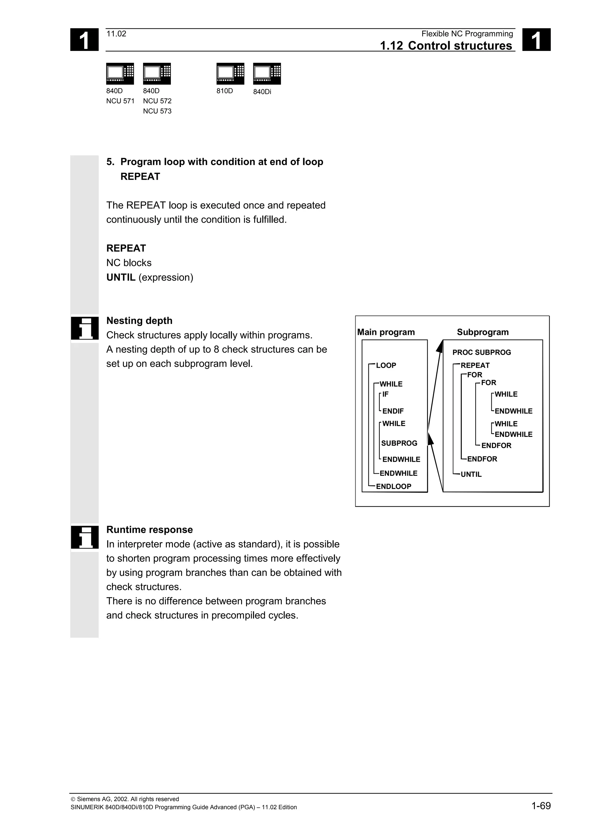
1-70 SINUMERIK 840D/840Di/810D Programming Guide Advanced (PGA) – 11.02 Edition
Supplementary conditions
Blocks with check structure elements cannot be
suppressed. Labels may not be used in blocks of
this type.
Check structures are processed interpretively. When
a loop end is detected, a search is made for the loop
beginning, allowing for the check structures found in
the process.
For this reason, the block structure of a program is
not checked completely in interpreter mode.
It is not generally advisable to use a mixture of
check structures and program branches.
A check can be made to ensure that check
structures are nested correctly when cycles are
preprocessed.
Check structures may only be inserted in the
statement section of a program. Definitions in the
program header may not be executed conditionally
or repeatedly.
It is not permissible to superimpose macros on
vocabulary words for check structures or on branch
destinations. No such check is made when the
macro is defined.
Programming example
1. Endless program
%_N_LOOP_MPF
LOOP
IF NOT $P_SEARCH ;No block search
G01 G90 X0 Z10 F1000
WHILE $AA_IM[X] <= 100
G1 G91 X10 F500 ;Drilling pattern
Z–5 F100
Z5](https://image.slidesharecdn.com/fadaladvancedprogrammingmanual-220505063253/75/Fadal-Advanced-Programming-Manual-pdf-70-2048.jpg)
![1
11.02 Flexible NC Programming
1.12 Control structures 1
840D
NCU 571
840D
NCU 572
NCU 573
810D 840Di
Siemens AG, 2002. All rights reserved
SINUMERIK 840D/840Di/810D Programming Guide Advanced (PGA) – 11.02 Edition 1-71
ENDWHILE
Z10
ELSE ;Block search
MSG("No drilling during block search")
ENDIF
$A_OUT[1]=1 ;Next drilling plate
G4 F2
ENDLOOP
M30
2. Production of a fixed quantity of parts
%_N_WKPCCOUNT_MPF
DEF INT WKPCCOUNT
FOR WKPCCOUNT = 0 TO 100
G01 …
ENDFOR
M30](https://image.slidesharecdn.com/fadaladvancedprogrammingmanual-220505063253/75/Fadal-Advanced-Programming-Manual-pdf-71-2048.jpg)
![1
11.02 Flexible NC Programming
1.15 Axis transfer, spindle transfer 1
840D
NCU 571
840D
NCU 572
NCU 573
810D 840Di
Siemens AG, 2002. All rights reserved
SINUMERIK 840D/840Di/810D Programming Guide Advanced (PGA) – 11.02 Edition 1-89
Set up variable axis transfer response
The release time of the axes can be set up using
MD 10722: AXCHANGE_MASK as follows:
• Automatic axis transfer between two channels
then also takes place when the axis has been
brought to a neutral state by WAITP (response
as before)
• From SW 5.3, it will only be possible to transfer
all the axes fetched to the axis container by GET
or GETD after an axis container rotation.
• From SW 6.4, when an intermediate block is
inserted in the main run, a check will be made to
determine whether or not reorganisation is
required. Reorganisation is only necessary if the
axis states of this block do not match the
current axis states.
Programming example
Activating an axis transfer without a preprocessing
stop
N010 M4 S100
N011 G4 F2
N020 M5
N021 SPOS=0
N022 POS[B]=1
N023 WAITP[B] Axis B becomes the neutral axis
N030 X1 F10
N031 X100 F500
N032 X200
N040 M3 S500
N041 G4 F2
N050 M5
N099 M30
Traverses the spindle (axis B) immediately after
block N023 as the PLC axis e.g. 180 degrees and
back 1 degree and back to the neutral axis. So block
N040 triggers neither a preprocessing stop nor a
reorganization.](https://image.slidesharecdn.com/fadaladvancedprogrammingmanual-220505063253/75/Fadal-Advanced-Programming-Manual-pdf-89-2048.jpg)
![1
Flexible NC Programming 11.02
1.16 NEWCONF: Setting machine data active (SW 4.3 and higher) 1
840D
NCU 571
840D
NCU 572
NCU 573
810D 840Di
Siemens AG, 2002. All rights reserved
1-90 SINUMERIK 840D/840Di/810D Programming Guide Advanced (PGA) – 11.02 Edition
1.16 NEWCONF: Setting machine data active (SW 4.3 and higher)
Function
All machine data of the effectiveness level
"NEW_CONFIG" are set active by means of the
NEWCONF language command. The function
corresponds to activating the soft key "Set MD active".
When the NEWCONF function is executed there is
an implicit preprocessing stop, that is, the path
movement is interrupted.
Explanation
NEWCONF All machine data of the "NEW_CONFIG" effectiveness level are set active
Programming example
Milling operation: Machining drilling position with
different technologies
N10 $MA_CONTOUR_TOL[AX]=1.0 ; Change machine data
N20 NEWCONF ; Set machine data active](https://image.slidesharecdn.com/fadaladvancedprogrammingmanual-220505063253/75/Fadal-Advanced-Programming-Manual-pdf-90-2048.jpg)
![1
11.02 Flexible NC Programming
1.17 WRITE: Write file (SW 4.3 and higher) 1
840D
NCU 571
840D
NCU 572
NCU 573
810D 840Di
Siemens AG, 2002. All rights reserved
SINUMERIK 840D/840Di/810D Programming Guide Advanced (PGA) – 11.02 Edition 1-91
1.17 WRITE: Write file (SW 4.3 and higher)
Programming
WRITE(var int error, char[160] filename, char[200] string)
The WRITE command appends a block to the end of the specified file.
Explanation of the parameters
error Error variable for return
0 No error
1 Path not allowed
2 Path not found
3 File not found
4 Incorrect file type
10 File is full
11 File is being used
12 No free resources
13 No access rights
20 Other error
filename Name of file in which the string is to be written.
The file name can be specified with path and file identifier. Path names
must be absolute, that is, starting with "/". If the file name does not
contain a domain identifier (_N_), it is added accordingly. If there is not
identifier (_MPF or _SPF), the file name is automatically completed with
_MPF. If there is no path specified, the file is saved in the current
directory (= directory of selected program). The file name length can be
up to 32 bytes, the path length up to 128 bytes.
Example: PROTFILE
_N_PROTFILE
_N_PROTFILE_MPF
/_N_MPF_DIR_/_N_PROTFILE_MPF/
string Text to be written. Internally LF is then added; this means that the text is
lengthened by one character.](https://image.slidesharecdn.com/fadaladvancedprogrammingmanual-220505063253/75/Fadal-Advanced-Programming-Manual-pdf-91-2048.jpg)
![1
11.02 Flexible NC Programming
1.18 DELETE: Delete file (SW 4.3 and higher) 1
840D
NCU 571
840D
NCU 572
NCU 573
810D 840Di
Siemens AG, 2002. All rights reserved
SINUMERIK 840D/840Di/810D Programming Guide Advanced (PGA) – 11.02 Edition 1-93
• If a file with the same name exists on the hard
disk, it is overwritten after the file is closed (in the
NC).
Remedy: Change the name in the NC under the
Services operating area using the "Properties"
soft key.
Machine manufacturer
Blocks from the parts program can be stored in a file
by means of the WRITE command. The file size for
log files (KB) is specified in the machine data.
1.18 DELETE: Delete file (SW 4.3 and higher)
Programming
DELETE(var int error, char[160] filename)
The DELETE command deletes the specified file.
Explanation of the parameters
error Error variable for return
0 No error
1 Path not allowed
2 Path not found
3 File not found
4 Incorrect file type
11 File is being used
12 No free resources
20 Other error
filename Name of the file to be deleted
The file name can be specified with path and file identifier. Path names
must be absolute, that is, starting with "/". If the file name does not
contain a domain identifier (_N_), it is added accordingly. The file
identifier ("-" plus 3 characters), e.g. _SPF) is optional. If there is no
identifier, the file name is automatically added _MPF. If there is no path
specified, the file is saved in the current directory (= directory of
selected program). The file name length can be up to 32 bytes, the path
length up to 128 bytes.](https://image.slidesharecdn.com/fadaladvancedprogrammingmanual-220505063253/75/Fadal-Advanced-Programming-Manual-pdf-93-2048.jpg)
![1
Flexible NC Programming 11.02
1.19 READ: Read lines in file (SW 5.2 and higher) 1
840D
NCU 571
840D
NCU 572
NCU 573
810D 840Di
Siemens AG, 2002. All rights reserved
1-94 SINUMERIK 840D/840Di/810D Programming Guide Advanced (PGA) – 11.02 Edition
Example: PROTFILE
_N_PROTFILE
_N_PROTFILE_MPF
/_N_MPF_DIR/_N_PROTFILE_MPF/
Function
All files can be deleted by means of the DELETE
command, irrespective of whether they were created
using the WRITE command or not. Files that were
created using a higher access authorization can also
be deleted with DELETE.
Programming example
N10 DEF INT ERROR ;
N15 STOPRE ; preprocessing stop
N20 DELETE (ERROR,
"/_N_SPF_DIR/_N_TEST1_SPF")
; deletes file TEST1 in the
; subroutine branch
N30 IF ERROR ;
N40 MSG ("Error with DELETE command:"
<<ERROR)
;
N50 M0 ;
N60 ENDIF ;
...
1.19 READ: Read lines in file (SW 5.2 and higher)
Programming
READ(var int error, string[160] file, int line, int number, var
string[255] result[])
The READ command reads one or several lines in the file specified and stores the information
read in an array of type STRING. In this array, each read line occupies an array element.](https://image.slidesharecdn.com/fadaladvancedprogrammingmanual-220505063253/75/Fadal-Advanced-Programming-Manual-pdf-94-2048.jpg)
![1
Flexible NC Programming 11.02
1.19 READ: Read lines in file (SW 5.2 and higher) 1
840D
NCU 571
840D
NCU 572
NCU 573
810D 840Di
Siemens AG, 2002. All rights reserved
1-96 SINUMERIK 840D/840Di/810D Programming Guide Advanced (PGA) – 11.02 Edition
Function
One or several lines can be read from a file with the
READ command. The lines read are stored in one
array element of an array. The information is
available as STRING.
Additional notes
• Binary files cannot be read in. The error message
error=4:Wrong type of file is output. The following
types of file are not readable: _BIN, _EXE, _OBJ,
_LIB, _BOT, _TRC, _ACC, _CYC, _NCK.
• The currently set protection level must be equal
to or greater than the READ right of the file. If this
is not the case, access is denied with error=13.
• If the number of lines specified in the parameter
"number" is smaller than the array length of
"result", the other array elements are not altered.
• Termination of a line by means of the control
characters "LF" (Line Feed) or "CR LF" (Carriage
Return Line Feed) is not stored in the target
variable "result". Read line are cut off, if the line is
longer than the string length of the target variable
"result". An error message is not output.
Programming example
N10 DEF INT ERROR ; error variable
N20 STRING[255] RESULT[5] ; result variable
...
N30 READ(ERROR, "TESTFILE", 1, 5,
RESULT)
; file name without domain and file identifier
...
N30 READ (ERROR, "TESTFILE_MPF", 1, 5,
RESULT)
; file name without domain and with file identifier
...
N30 READ(ERROR,"_N_TESTFILE_MPF",1,5,
RESULT)
; file name with domain and file identifier](https://image.slidesharecdn.com/fadaladvancedprogrammingmanual-220505063253/75/Fadal-Advanced-Programming-Manual-pdf-96-2048.jpg)
![1
11.02 Flexible NC Programming
1.20 ISFILE: File available in user memory NCK (SW 5.2 and higher) 1
840D
NCU 571
840D
NCU 572
NCU 573
810D 840Di
Siemens AG, 2002. All rights reserved
SINUMERIK 840D/840Di/810D Programming Guide Advanced (PGA) – 11.02 Edition 1-97
...
N30 READ(ERROR,"/_N_CST_DIR/N_TESTFILE
_MPF", 1, 5 RESULT)
; file name with domain and file identifier and
path specification
^...
N40 IF ERROR <>0 ; error evaluation
N50 MSG("ERROR"<<ERROR<<" WITH READ COMMAND")
N60 M0
N70 ENDIF
...
1.20 ISFILE: File available in user memory NCK (SW 5.2 and higher)
Programming
result=isfile(string[160]file)
With the ISFILE command you check whether a file exists in the user memory of the NCK
(passive file system). As a result either TRUE (file exists) or False (file does not exist) is returned.
Explanation of the parameters
file Name/path of the file to be read (call-by-value parameter of type
STRING with a max. length of 160 bytes).
The file must be stored in the user memory of the NCK (passive file
system). The file name can be preceded by the domain identifier _N_. If
the domain identifier is missing, it is added correspondingly.
The file identifier ("_" plus three characters, e.g. _SPF) is optional. If
there is no identifier, the file name is automatically added _MPF.
If there is no path specified in "file", the file is searched for in the current
directory (=directory of selected program). If a path is specified in "file",
it must start with a slash "/" (absolute path indication).
result Variable for storage of the result of type BOOL (TRUE or FALSE)](https://image.slidesharecdn.com/fadaladvancedprogrammingmanual-220505063253/75/Fadal-Advanced-Programming-Manual-pdf-97-2048.jpg)
![1
Flexible NC Programming 11.02
1.21 CHECKSUM: Creation of a checksum over an array 1
840D
NCU 571
840D
NCU 572
NCU 573
810D 840Di
Siemens AG, 2002. All rights reserved
1-98 SINUMERIK 840D/840Di/810D Programming Guide Advanced (PGA) – 11.02 Edition
Programming example
N10 DEF BOOL RESULT
N20 RESULT=ISFILE("TESTFILE")
N30 IF(RESULT==FALSE)
N40 MSG("FILE DOES NOT EXIST")
N50 M0
N60 ENDIF
...
or:
N30 IF(NOT ISFILE("TESTFILE"))
N40 MSG("FILE DOES NOT EXIST")
N50 M0
N60 ENDIF
...
1.21 CHECKSUM: Creation of a checksum over an array
(SW 5.2 and higher)
Programming
error=CHECKSUM(var string[16] chksum,string[32]array, int first, int
last)
The CHECKSUM function forms the checksum over an array.
Explanation of the parameters
error Error variable for return Representation
0 No error
1 Symbol not found
2 No array
3 Index 1 too large
4 Index 2 too large
5 Invalid type of file
10 Checksum overflow
chksum Checksum over the array as a string (call-by-reference parameter of
type String, with a defined length of 16).
The checksum is indicated as a character string of 16 hexadecimal
numbers. However, no format characters are indicated.
Example: in MY_CHECKSUM](https://image.slidesharecdn.com/fadaladvancedprogrammingmanual-220505063253/75/Fadal-Advanced-Programming-Manual-pdf-98-2048.jpg)
![1
11.02 Flexible NC Programming
1.21 CHECKSUM: Creation of a checksum over an array 1
840D
NCU 571
840D
NCU 572
NCU 573
810D 840Di
Siemens AG, 2002. All rights reserved
SINUMERIK 840D/840Di/810D Programming Guide Advanced (PGA) – 11.02 Edition 1-99
array Number of the array over which the checksum is to be formed. (Call-by-
value parameter of type String with a max. length of 32).
Permissible arrays: 1 or 2-dimensional arrays of types
BOOL, CHAR, INT, REAL, STRING
Arrays of machine data are not permissible.
first Column number of start column (optional)
last Column number of end column (optional)
Function
With CHECKSUM you form a checksum over an
array.
Stock removal application:
Check to see whether the initial contour has changed.
Additional notes
The parameters first and last are optional. If no
column indices are indicated, the checksum is
formed over the whole array.
The result of the checksum is always definite. If an
array element is changed, the result string will also
be changed.
Programming example
N10 DEF INT ERROR
N20 DEF STRING[16] MY_CHECKSUM
N30 DEF INT MY_VAR[4,4]
N40 MY_VAR=...
N50 ERROR=CHECKSUM
(CHECKSUM;"MY_VAR", 0, 2)
...
returns in MY_CHECKSUM the value
"A6FC3404E534047C"
n](https://image.slidesharecdn.com/fadaladvancedprogrammingmanual-220505063253/75/Fadal-Advanced-Programming-Manual-pdf-99-2048.jpg)
![2
11.02 Subprograms, Macros
2.3 Subprograms with parameter transfer 2
840D
NCU 571
840D
NCU 572
NCU 573
810D 840Di
Siemens AG, 2002. All rights reserved
SINUMERIK 840D/840Di/810D Programming Guide Advanced (PGA) – 11.02 Edition 2-107
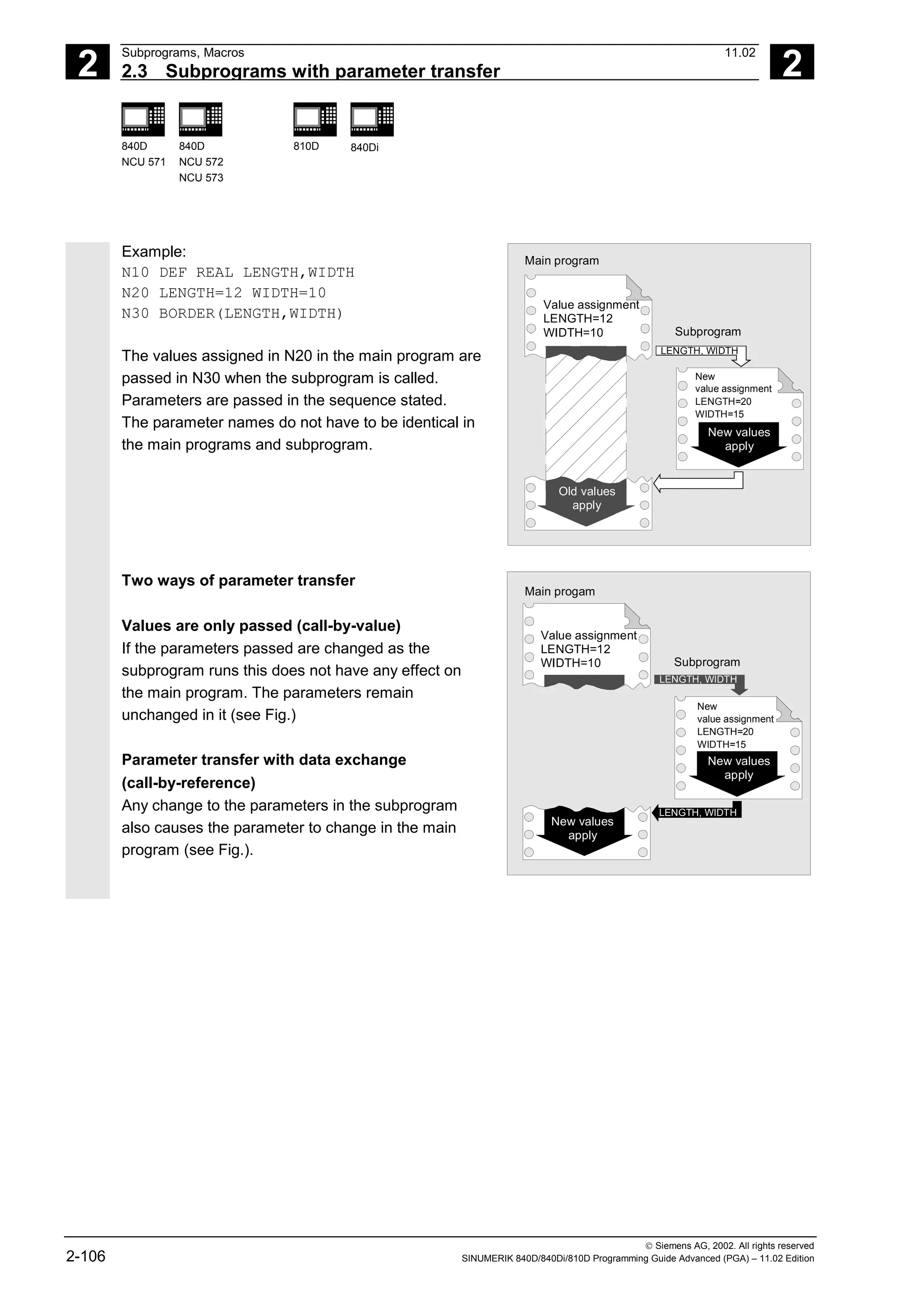
Programming
The parameters relevant for parameter transfer must be
listed at the beginning of the subprogram with their type
and name.
Parameter transfer call-by-value
PROC PROGRAM_NAME(VARIABLE_TYPE1 VARIABLE1,VARIABLE_TYPE2 VARIABLE2,...)
Example:
PROC CONTOUR(REAL LENGTH, REAL WIDTH)
Parameter transfer call-by-reference,
identification with vocabulary word VAR
PROC PROGRAM_NAME(VARIABLE_TYPE1 VARIABLE1,VARIABLE_TYPE2 VARIABLE2, ...)
Example:
PROC CONTOUR(VAR REAL LENGTH, VAR REAL WIDTH)
Array transfer with call-by-reference,
identification with vocabulary word VAR
PROC PROGRAM_NAME(VAR VARIABLE_TYPE1 ARRAY_NAME1[array size],
VAR VARIABLE_TYPE2 ARRAY_NAME2[array size], VAR VARIABLE_TYPE3
ARRAY_NAME3[array size1, array size2], VAR VARIABLE_TYPE4 ARRAY_NAME4[ ],
VAR VARIABLE_TYPE5 ARRAY_NAME5 [,array size])
Example:
PROC PALLET (VAR INT ARRAY[,10])
Additional notes
The definition statement with PROC must be
programmed in a separate NC block. A maximum of
127 parameters can be declared for parameter transfer.](https://image.slidesharecdn.com/fadaladvancedprogrammingmanual-220505063253/75/Fadal-Advanced-Programming-Manual-pdf-107-2048.jpg)
![2
Subprograms, Macros 11.02
2.3 Subprograms with parameter transfer 2
840D
NCU 571
840D
NCU 572
NCU 573
810D 840Di
Siemens AG, 2002. All rights reserved
2-108 SINUMERIK 840D/840Di/810D Programming Guide Advanced (PGA) – 11.02 Edition
Array definition
The following applies to the definition of the formal
parameters:
With two-dimensional arrays the number of fields in
the first dimension does not need to be specified, but
the comma must be written.
Example:
VAR REAL ARRAY[,5]
With certain array dimensions it is possible to process
subprograms with arrays of variable length. However,
when defining the variables you must define how many
elements it is to contain.
See the Programming Guide "Advanced" for an
explanation of array definition.
Programming example
Programming with variable array dimensions
%_N_DRILLING_PLATE_MPF Main program
DEF REAL TABLE[100,2] Define position table
EXTERN DRILLING_PATTERN
(VAR REAL[,2],INT)
TABLE[0.0]=-17.5 Define positions
…
TABLE[99.1]=45
DRILLING_PATTERN(TABLE,100) Subprogram call
M30
Creating a drilling pattern using the position table of variable dimension passed
%_N_DRILLING_PATTERN_SPF Subprogram
PROC DRILLING_PATTERN(VAR REAL ARRAY[,2],->
-> INT NUMBER)
Parameters passed
DEF INT COUNT
STEP: G1 X=ARRAY[COUNT,0]->
-> Y=ARRAY[COUNT,1] F100
Machining sequence
Z=IC(-5)
Z=IC(5)
COUNT=COUNT+1
IF COUNT<NUMBER GOTOB STEP
RET End of subprogram](https://image.slidesharecdn.com/fadaladvancedprogrammingmanual-220505063253/75/Fadal-Advanced-Programming-Manual-pdf-108-2048.jpg)
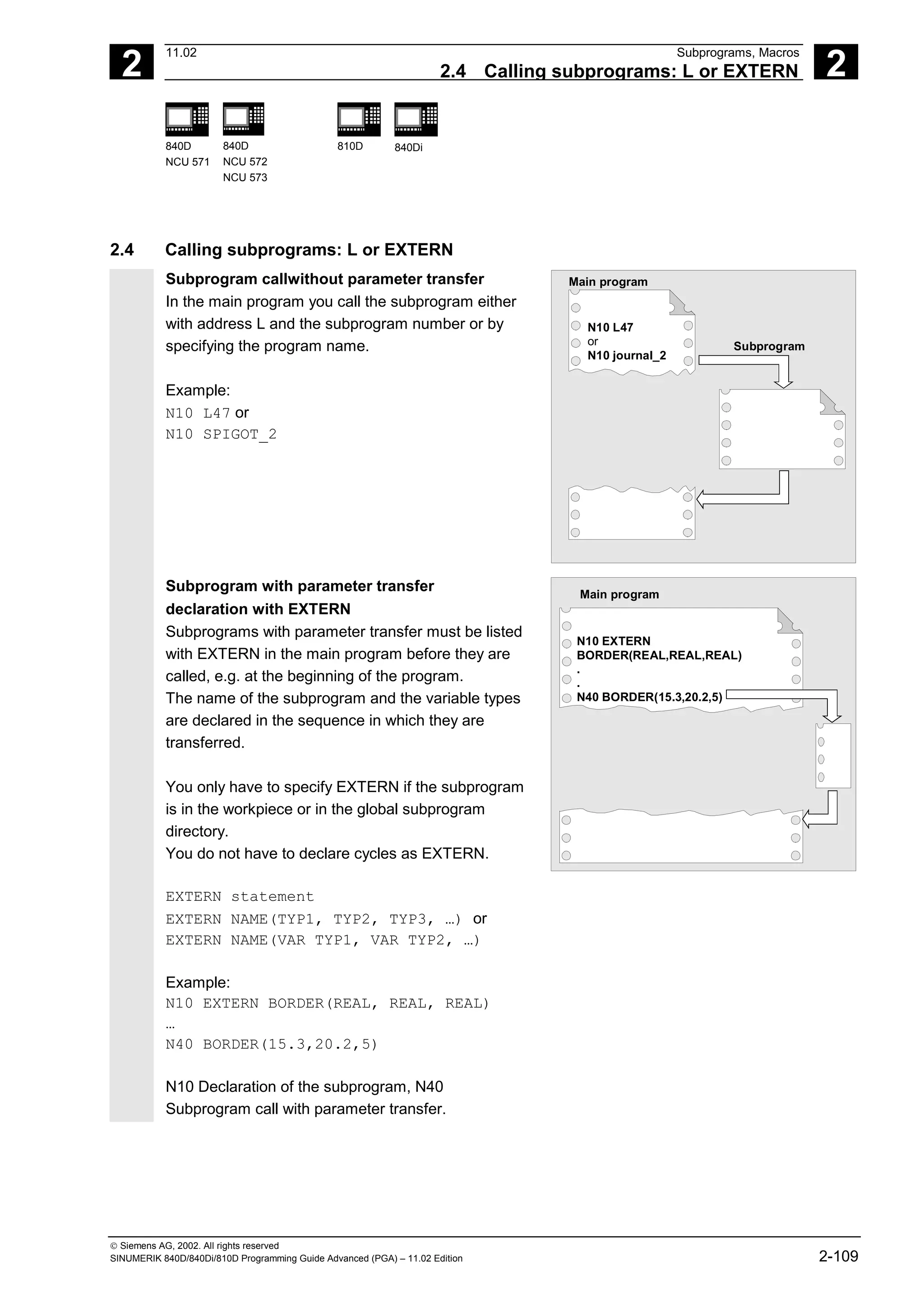
![2
11.02 Subprograms, Macros
2.4 Calling subprograms: L or EXTERN 2
840D
NCU 571
840D
NCU 572
NCU 573
810D 840Di
Siemens AG, 2002. All rights reserved
SINUMERIK 840D/840Di/810D Programming Guide Advanced (PGA) – 11.02 Edition 2-111
Incomplete parameter transfer
In a subprogram call only mandatory values and
parameters can be omitted. In this case, the
parameter in question is assigned the value zero in
the subprogram.
The comma must always be written to indicate the
sequence. If the parameters are at the end of the
sequence you can omit the comma as well.
Back to the last example:
N40 BORDER(15.3, ,5)
The mean value 20.2 was omitted here.
Note
Main program
N30 LENGTH=15.3 WIDTH=20.2 WIDTH=5
N40 BORDER(15.3,20.2,5)
The current parameter of type AXIS must not be
omitted.
VAR parameters must be passed on completely.
SW 4.4 and higher:
With incomplete parameter transfer, it is possible to
tell by the system variable $P_SUBPAR[i] whether
the transfer parameter was programmed for
subprograms or not.
The system variable contains as argument (i) the
number of the transfer parameter.
The system variable $P_SUBPAR returns
• TRUE, if the transfer parameter was
programmed
• FALSE, if no value was set as transfer
parameter.
If an impermissible parameter number was
specified, parts program processing is aborted with
alarm output.](https://image.slidesharecdn.com/fadaladvancedprogrammingmanual-220505063253/75/Fadal-Advanced-Programming-Manual-pdf-111-2048.jpg)
![2
Subprograms, Macros 11.02
2.4 Calling subprograms: L or EXTERN 2
840D
NCU 571
840D
NCU 572
NCU 573
810D 840Di
Siemens AG, 2002. All rights reserved
2-112 SINUMERIK 840D/840Di/810D Programming Guide Advanced (PGA) – 11.02 Edition
Example:
Subprogram
PROC SUB1 (INT VAR1, DOUBLE VAR2)
IF $P_SUBPAR[1]==TRUE
;Parameter VAR1 was not
;in the subprogram call
ELSE
;Parameter VAR1 was not
;programmed in the subprogram call
;and was preset by the system
;with default value 0
ENDIF
IF $P_SUBPAR[2]==TRUE
;Parameter VAR2 was not
;in the subprogram call
ELSE
;Parameter VAR2 was not
;programmed in the subprogram call
;and was preset by the system
;with default value 0.0
ENDIF
;Parameter 3 is not defined
IF $P_SUBPAR[3]==TRUE -> Alarm 17020
M17
Calling the main program as a subprogram
A main program can also be called as subprogram.
The end of program M2 or M30 set in the main
program is evaluated as M17 in this case (end of
program with return to the calling program).
Program the call by specifying the program name.
Example:
N10 MPF739 or
N10 SHAFT3
Main program
N10 MPF739
or
N10 SHAFT3
Further
main program
N10...
.
.
.
N50 M30
A subprogram can also be started as a main
program.](https://image.slidesharecdn.com/fadaladvancedprogrammingmanual-220505063253/75/Fadal-Advanced-Programming-Manual-pdf-112-2048.jpg)
![2
11.02 Subprograms, Macros
2.8 Calling the subprogram indirectly: CALL 2
840D
NCU 571
840D
NCU 572
NCU 573
810D 840Di
Siemens AG, 2002. All rights reserved
SINUMERIK 840D/840Di/810D Programming Guide Advanced (PGA) – 11.02 Edition 2-119
2.8 Calling the subprogram indirectly: CALL
Programming
CALL <progname>
Explanation
CALL Vocabulary word for indirect subprogram
call
<progname> Variable or constant of type string
Name of the program containing the
program section to run
Indirect subprogram call, CALL
Depending on the prevailing conditions at a
particular point in the program, different
subprograms can be called.
The name of the subprogram is stored in a variable
of type STRING. The subprogram call is issued with
CALL and the variable name.
The indirect subprogram call is only possible for
subprograms without parameter transfer.
For direct calling of the subprogram, store the name
in a string constant.
Example:
Direct call with string constant:
CALL "/_N_WCS_DIR/_N_SUBPROG_WPD/_N_PART1_SPF"
Indirect call via variable:
DEF STRING[100] PROGNAME
PROGNAME="/_N_WCS_DIR/_N_SUBPROG_WPD/_N_PART1_SPF"
CALL PROGNAME
The subprogram PART1 is assigned the variable
PROGNAME. With CALL and the path name you
can call the subprogram indirectly.](https://image.slidesharecdn.com/fadaladvancedprogrammingmanual-220505063253/75/Fadal-Advanced-Programming-Manual-pdf-119-2048.jpg)
![2
Subprograms, Macros 11.02
2.9 Repeating program sections with indirect programming 2
840D
NCU 571
840D
NCU 572
NCU 573
810D 840Di
Siemens AG, 2002. All rights reserved
2-120 SINUMERIK 840D/840Di/810D Programming Guide Advanced (PGA) – 11.02 Edition
2.9 Repeating program sections with indirect programming
(SW 6.4 and higher)
Programming
CALL <progname> BLOCK <startlabel> TO <endlabel>
CALL BLOCK <startlabel> TO <endlabel>
Explanation
CALL Vocabulary word for indirect subprogram
call
<progname> (optional) Variable or constant of type string, name
of the program containing the program
section to run.
If no <progname> is programmed, the
program section with <startlabel>
<endlabel> in the current program is
searched for and run.
BLOCK ... TO ... Vocabulary word for indirect program
section repetition
<startlabel> <endlabel> Variable or constant of type string
Refers to the beginning or end of the
program section to run
Function
CALL is used to call up subprogram indirectly in which
the program section repetitions defined with BLOCK are
run according to the start label and end label.
Programming example
DEF STRING[20] STARTLABEL, ENDLABEL
STARTLABEL = "LABEL_1"
ENDLABEL = "LABEL_2"
...
CALL "CONTUR_1" BLOCK STARTLABEL TO ENDLABEL ...
M17
PROC CONTUR_1 ...
LABEL_1 ; Beginning of program section repetition
N1000 G1 ...
LABEL_2 ; End of program section repetition](https://image.slidesharecdn.com/fadaladvancedprogrammingmanual-220505063253/75/Fadal-Advanced-Programming-Manual-pdf-120-2048.jpg)
![2
11.02 Subprograms, Macros
2.10 Calling up a program in ISO language indirectly: ISOCALL 2
840D
NCU 571
840D
NCU 572
NCU 573
810D 840Di
Siemens AG, 2002. All rights reserved
SINUMERIK 840D/840Di/810D Programming Guide Advanced (PGA) – 11.02 Edition 2-121
2.10 Calling up a program in ISO language indirectly: ISOCALL
Programming
ISOCALL <progname>
Explanation
ISOCALL Subprogram call with which the ISO
mode set in the machine data is activated
<progname> Variable or constant of type string
Name of the program in ISO language.
Function
The indirect program call ISOCALL is used to call up
a program in ISO language. The ISO mode set in the
machine data is activated
At the end of the program, the original mode is
reactivated. If no ISO mode is set in the machine
data, the subprogram is called in Siemens mode.
For more information about ISO mode, see
/FBFA/, "Description of Functions ISO Dialects"
Example:
Calling up a contour from ISO mode with cycle
programming:
%_N_0122_SPF
N1010 G1 X10 Z20
N1020 X30 R5
N1030 Z50 C10
N1040 X50
N1050 M99
N0010 DEF STRING[5] PROGNAME = "0122"
...
N2000 R11 = $AA_IW[X]
N2010 ISOCALL PROGNAME
N2020 R10 = R10+1
N2300 ...
N2400 M30
Contour description in ISO mode
Siemens parts program (cycle)
Run program 0122.spf in ISO mode](https://image.slidesharecdn.com/fadaladvancedprogrammingmanual-220505063253/75/Fadal-Advanced-Programming-Manual-pdf-121-2048.jpg)
![2
11.02 Subprograms, Macros
2.17 Cycles: Setting parameters for user cycles 2
840D
NCU 571
840D
NCU 572
NCU 573
810D 840Di
Siemens AG, 2002. All rights reserved
SINUMERIK 840D/840Di/810D Programming Guide Advanced (PGA) – 11.02 Edition 2-139
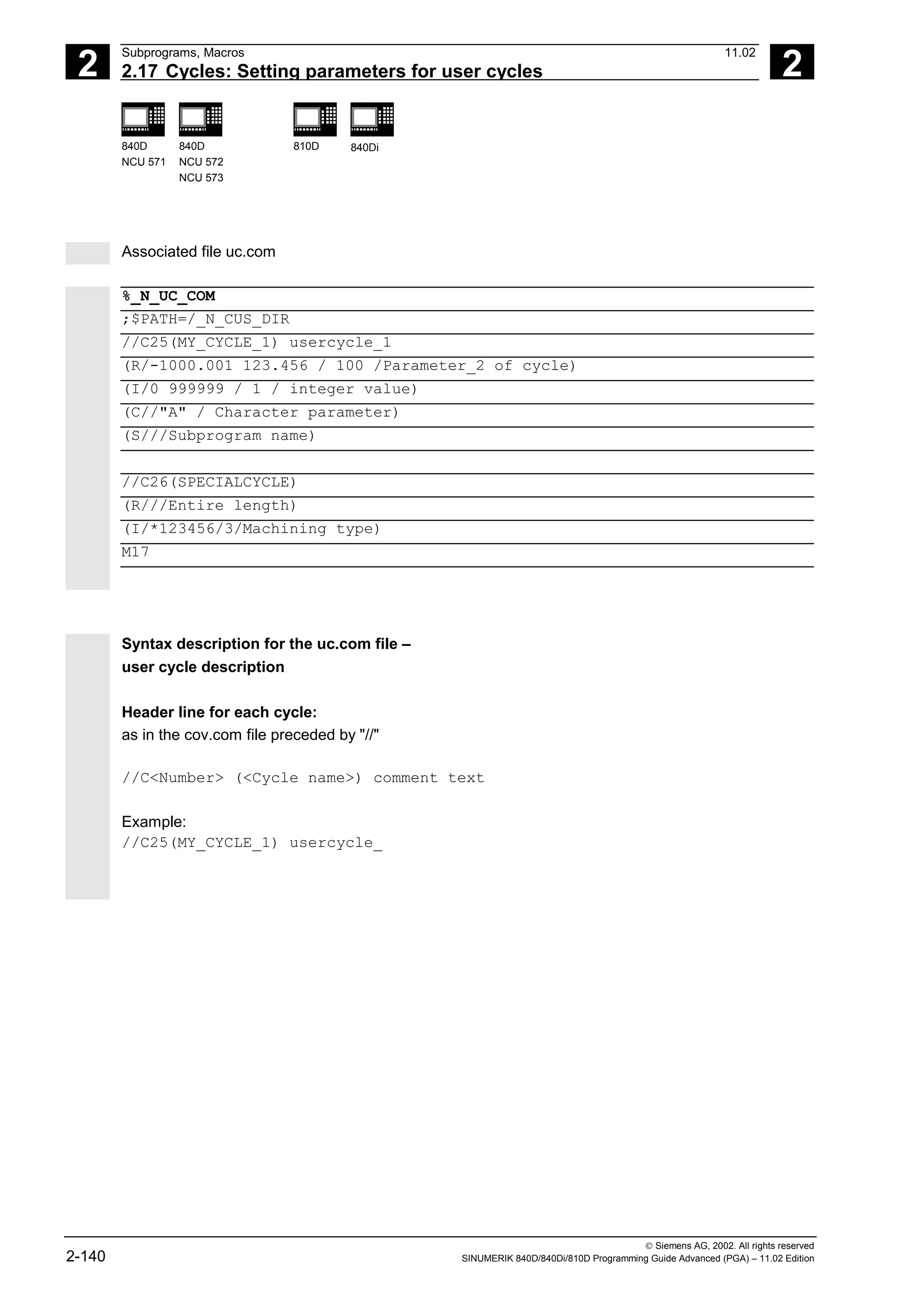
For each newly added cycle a line must be added
with the following syntax:
C<Number> (<Cycle name>) comment text
Number: Any integer, must not have been used in
the file before;
Cycle name: The program name of the cycle to be
included
Comment text: Optionally a comment text for the
cycle
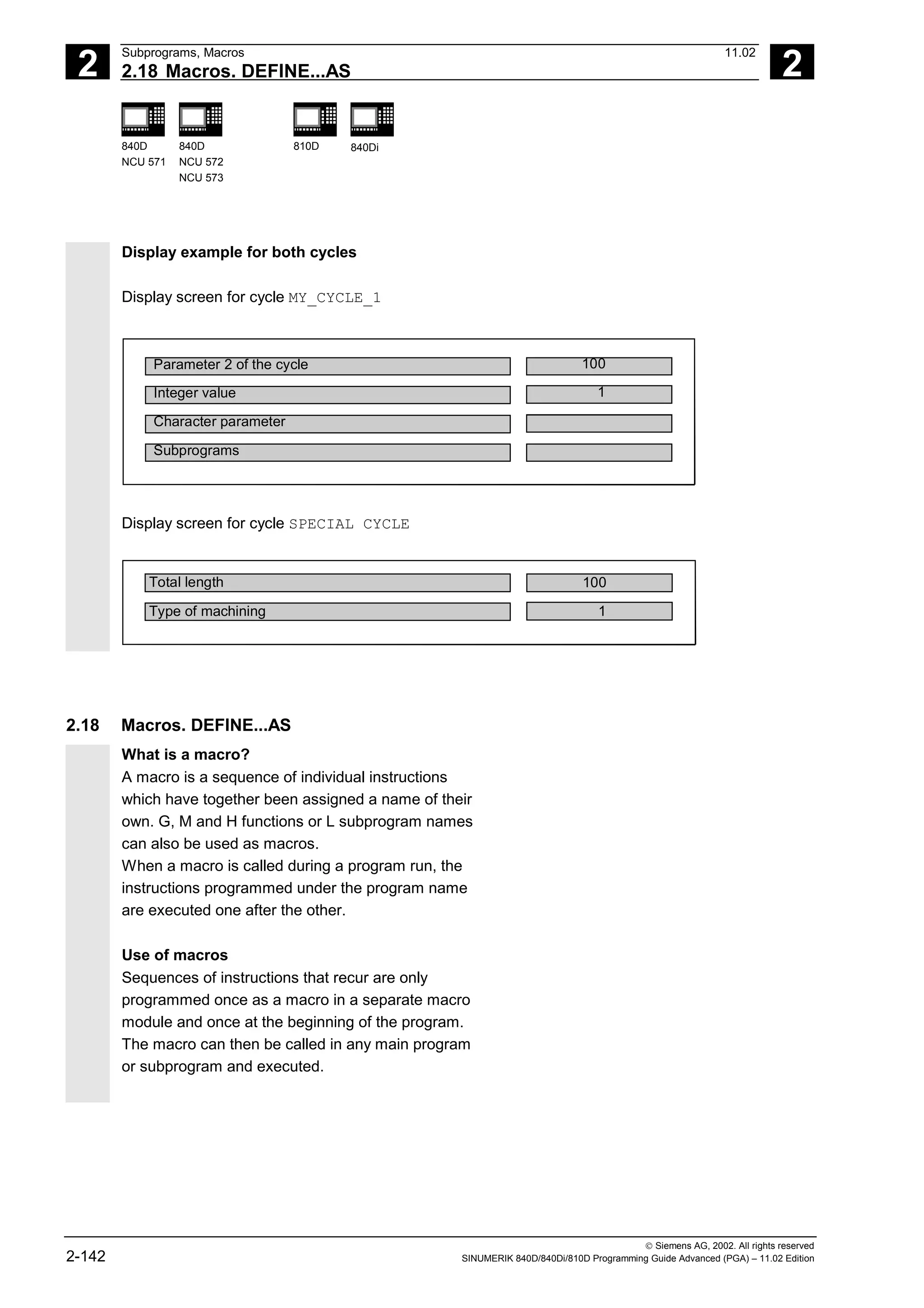
Example:
C25 (MY_CYCLE_1) usercycle_1
C26 (SPECIAL CYCLE)
Example of uc.com file
User cycle description
The explanation is based on the continuation of the
example:
For the following two cycles a cycle parameterization
is to be newly created:
PROC MY_CYCLE_1 (REAL PAR1, INT PAR2, CHAR PAR3, STRING[10] PAR4)
;The cycle has the following transfer parameters:
;
;PAR1: Real value in range -1000.001 <= PAR2 <= 123.456, default with 100
;PAR2: Positive integer value between 0 <= PAR3 <= 999999, Default with 0
;PAR3: 1 ASCII character
;PAR4: String of length 10 for a subprogram name
;
...
M17
PROC SPECIALCYCLE (REAL VALUE1, INT VALUE2)
;The cycle has the following transfer parameters:
;
;VALUE1: Real value without value range limitation and default
;VALUE2: Integer value without value range limitation and default
...
M17](https://image.slidesharecdn.com/fadaladvancedprogrammingmanual-220505063253/75/Fadal-Advanced-Programming-Manual-pdf-139-2048.jpg)
![3
11.02 File and Program Management
3.3 User memory 3
840D
NCU 571
840D
NCU 572
NCU 573
810D 840Di
© Siemens AG, 2002. All rights reserved
SINUMERIK 840D/840Di/810D Programming Guide Advanced (PGA) – 11.02 Edition 3-155
Procedure for multi-channel controls
CHANDATA (channel number) for several channels
is only permitted in the file N_INITIAL_INI.
N_INITIAL_INI is the installation file with which all
data of the control is initialized.
Example:
%_N_INITIAL_INI
CHANDATA(1)
;Machine axis assignment channel 1
$MC_AXCONF_MACHAX_USED[0]=1
$MC_AXCONF_MACHAX_USED[1]=2
$MC_AXCONF_MACHAX_USED[2]=3
CHANDATA(2)
;Machine axis assignment channel 2
$MC_AXCONF_MACHAX_USED[0]=4
$MC_AXCONF_MACHAX_USED[1]=5
CHANDATA(1)
;axial machine data
;Exact stop window coarse:
$MA_STOP_LIMIT_COARSE[AX1]=0.2 ;Axis 1
$MA_STOP_LIMIT_COARSE[AX2]=0.2 ;Axis 2
;Exact stop window fine:
$MA_STOP_LIMIT_COARSE[AX1]=0.01 ;Axis 1
$MA_STOP_LIMIT_COARSE[AX1]=0.01 ;Axis 2
In the parts program, the CHANDATA instruction
may only be used for the channel on which the NC
program is running, i.e. the instruction can be used
to protect NC programs from being executed
accidentally on a different channel.
Program processing is aborted if an error occurs.
Note
INI files in job lists do not contain any CHANDATA
instructions.](https://image.slidesharecdn.com/fadaladvancedprogrammingmanual-220505063253/75/Fadal-Advanced-Programming-Manual-pdf-155-2048.jpg)
![3
11.02 File and Program Management
3.4 Defining user data 3
840D
NCU 571
840D
NCU 572
NCU 573
810D 840Di
© Siemens AG, 2002. All rights reserved
SINUMERIK 840D/840Di/810D Programming Guide Advanced (PGA) – 11.02 Edition 3-157
Defining user data (GUD)
1. Save module _N_INITIAL_INI.
2. Creating a definition file for user data
• on an external PC (SW 4 and lower)
• in the Services operating area (SW 5 and
higher)
Predefined file names are provided (see previous
page):
_N_SGUD_DEF
_N_MGUD_DEF
_N_UGUD_DEF
_N_GUD4_DEF … _N_GUD9_DEF
Files with these names can contain definitions
for GUD variables.
Programming
The GUD variables are programmed with the DEF
command:
DEF scope preproc. stop type name[.., ...]=value
Explanation
Scope Range identifies the variable as a GUD
variable and defines its validity scope:
NCK Throughout NCK
CHAN Throughout channel
Preproc. stop Optional attribute preprocessing stop:
SYNR Preprocessing stop while
reading
SYNW Preprocessing stop while
writing
SYNRW Preprocessing stop while
reading/writing
Type Data type
BOOL
REAL
INT
AXIS
FRAME
STRING
CHAR](https://image.slidesharecdn.com/fadaladvancedprogrammingmanual-220505063253/75/Fadal-Advanced-Programming-Manual-pdf-157-2048.jpg)
![3
File and Program Management 11.02
3.4 Defining user data 3
840D
NCU 571
840D
NCU 572
NCU 573
810D 840Di
© Siemens AG, 2002. All rights reserved
3-158 SINUMERIK 840D/840Di/810D Programming Guide Advanced (PGA) – 11.02 Edition
Name Variable name
[.., ...] Optional run limits for array variables
Value Optional preset value,
two or more values for arrays, separated
by commas
REP (w1) , SET(w1, W2, ...), (w1, w2, ...)
Initialization values are not possible for
type Frame
3. Load the definition file in the program memory of
the control.
The control always creates a default directory
_N_DEF_DIR.
This name is entered as the path in the header of
the GUD definition file and evaluated when read
in via the RS-232 interface.
Programming example
Example of a definition file, global data (Siemens):
%_N_SGUD_DEF
;$PATH=/_N_DEF_DIR
DEF NCK REAL RTP ;Retraction plane
DEF CHAN INT SDIS ;Safety clearance
M30](https://image.slidesharecdn.com/fadaladvancedprogrammingmanual-220505063253/75/Fadal-Advanced-Programming-Manual-pdf-158-2048.jpg)
![3
11.02 File and Program Management
3.4 Defining user data 3
840D
NCU 571
840D
NCU 572
NCU 573
810D 840Di
© Siemens AG, 2002. All rights reserved
SINUMERIK 840D/840Di/810D Programming Guide Advanced (PGA) – 11.02 Edition 3-159
4. Activating definition files
• SW 4 and lower
Before read-in of the _N_INITIAL_INI, save
all programs, frames, and machine data
because the static memory will be formatted
The definition file is only reactivated on read-in
of the _N_INITIAL_INI file.
• SW 5 and higher
When the GUD definition file is loaded into the
NC ("Load" soft key), it becomes active. See
"Automatic activation ..."
5. Data storage
When the file _N_COMPLETE_GUD is archived
from the working memory, only the data
contained in the file are saved. The definition files
created for the global user variables must be
archived separately.
The variable assignments to global user data are
also stored in _N_INITIAL_INI, the names
must be identical with the names in the definition
files.
Example of a definition file for global data
(machine manufacturer):
%_N_MGUD_DEF
;$PATH=/_N_DEF_DIR
;Global data definitions of the machine manufacturer
DEF NCK SYNRW INT QUANTITY ;Implicit preprocessing stop during read/write
;Spec. data available in the control
;Access from all channels
DEF CHAN INT TOOLTABLE[100] ;Tool table for channel-spec. image
;of the tool number at magazine locations
M30 ;Separate table created for each channel](https://image.slidesharecdn.com/fadaladvancedprogrammingmanual-220505063253/75/Fadal-Advanced-Programming-Manual-pdf-159-2048.jpg)
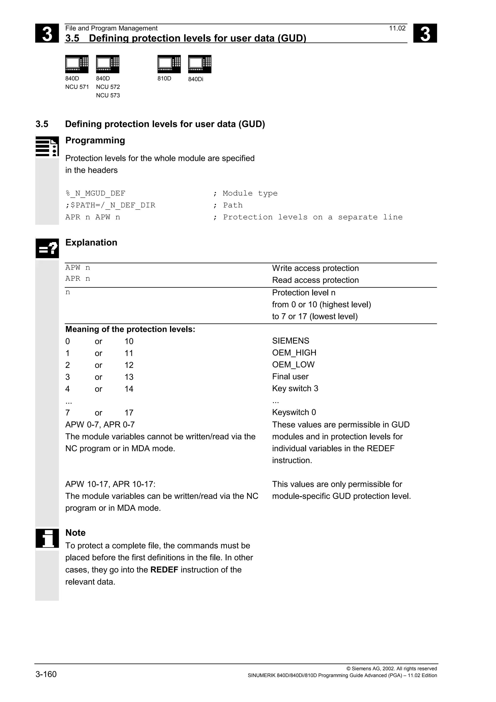
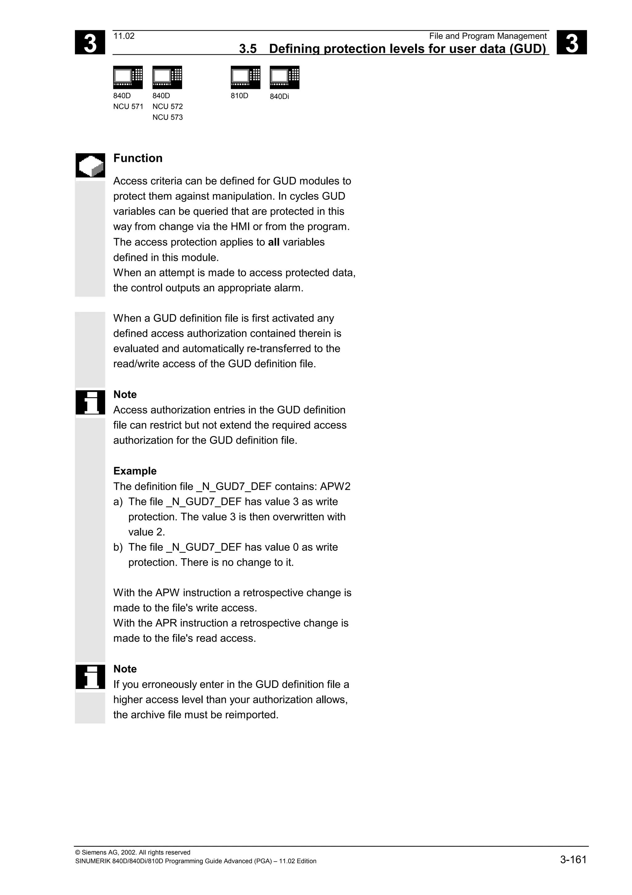
![3
File and Program Management 11.02
3.8 Changing attributes of NC language elements (SW 6.4 and higher) 3
840D
NCU 571
840D
NCU 572
NCU 573
810D 840Di
© Siemens AG, 2002. All rights reserved
3-170 SINUMERIK 840D/840Di/810D Programming Guide Advanced (PGA) – 11.02 Edition
DEF NCK INT _MYGUS[10,10]
REDEF _MYGUD INIRE // ok
REDEF _MYGUD[1,1] INIRE // not possible, alarm output
// (array value)
Initialization of GUD arrays themselves is not
affected.
DEF NCK INT _MYGUD[10] =(0, 1, 2, 3, 4, 5, 6, 7, 8, 9)
DEF NCK INT _MYGUD[100,100] = REP (12)
DEF NCK INT _MYGUD[100,100] ;
Make sure that a sufficiently large memory for init
values (MD 18150: MM_GUD_VAL_MEM) is
available when setting INI attributes for these
variables. In MD 11270:
DEFAULT_VALUES_MEM_MASK, Bit1 = 1 must be
set (memory for initialization values active).
For R and system parameters it is not possible to
specify a default that deviates from the compiled value.
However, resetting to the compiled value is possible
with INIPO, INIRE, or INICF.
For data type FRAME of GUD it is not possible to
specify a default deviating from the compiled value
either (like for definition of the data item).](https://image.slidesharecdn.com/fadaladvancedprogrammingmanual-220505063253/75/Fadal-Advanced-Programming-Manual-pdf-170-2048.jpg)
![3
11.02 File and Program Management
3.9 Structuring instruction SEFORM in the Step editor 3
840D
NCU 571
840D
NCU 572
NCU 573
810D 840Di
© Siemens AG, 2002. All rights reserved
SINUMERIK 840D/840Di/810D Programming Guide Advanced (PGA) – 11.02 Edition 3-173
3.9 Structuring instruction SEFORM in the Step editor
(SW 6.4 and higher)
Programming
SEFORM(STRING[128] section_name, INT level, STRING[128] icon)
Explanation of the parameters
SEFORM Function call of structuring instruction
with parameters:
section_name, level, and icon
section_name Identifier of the operation
level Index for the main or sublevel.
=0 means main level
=1, ... means sublevel 1 to n
icon Name of the icon displayed for this
section.
Function
The SEFORM instruction is evaluated in the Step
editor to generate the step view for HMI Advanced
The step view is available as from SW 6.3 on HMI
Advanced and makes for better readability of the NC
subprogram. The SEFORM structuring instruction
supports Step editor (editor-based program support)
over the three specified parameters.](https://image.slidesharecdn.com/fadaladvancedprogrammingmanual-220505063253/75/Fadal-Advanced-Programming-Manual-pdf-173-2048.jpg)
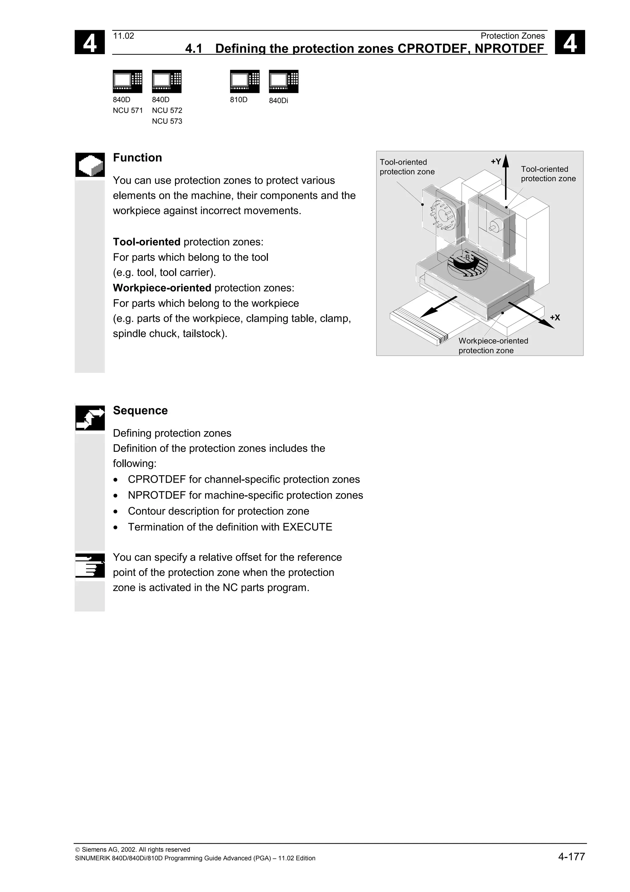
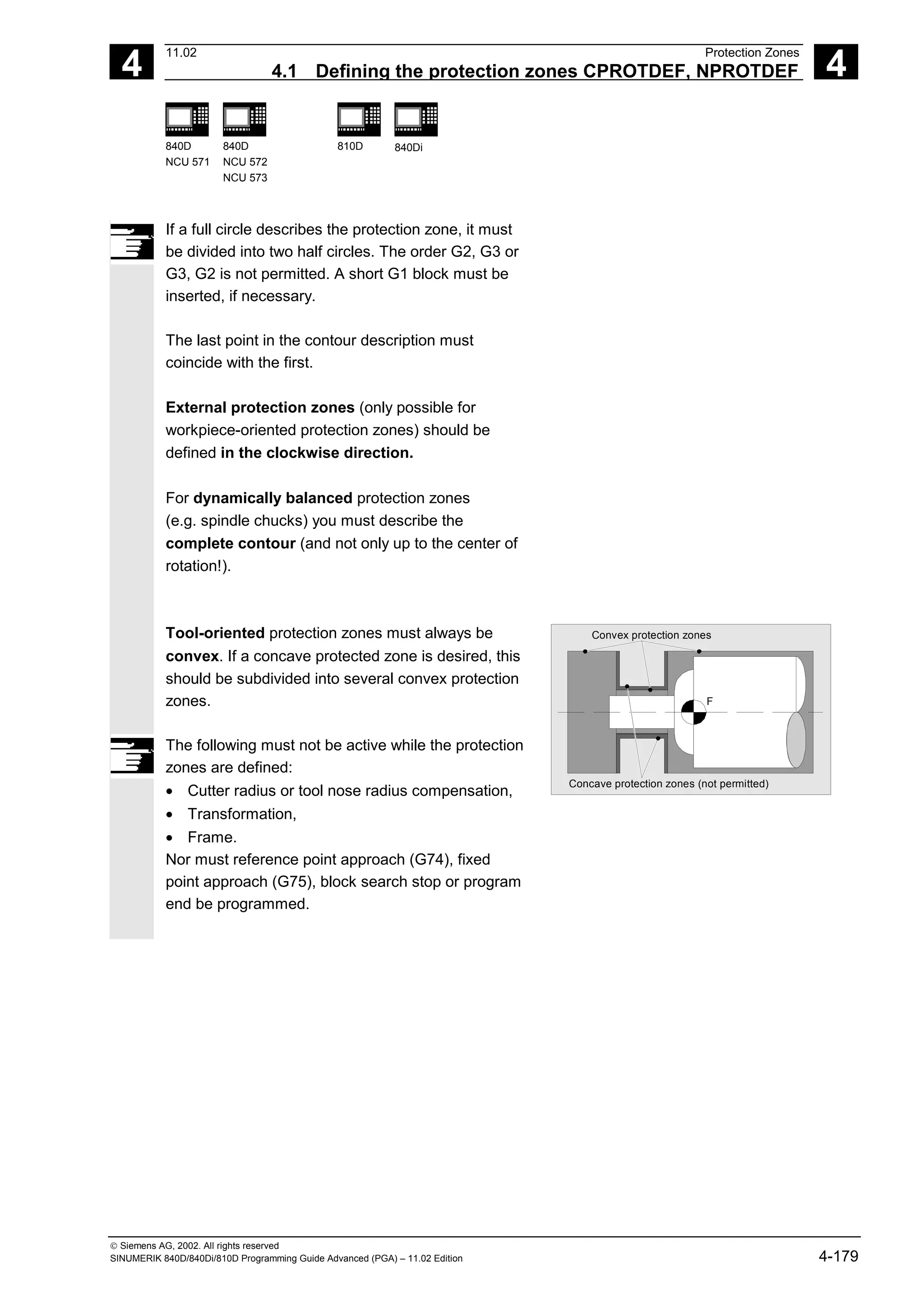
![4
11.02 Protection Zones
4.2 Activating/deactivating protection zones: CPROT, NPROT 4
840D
NCU 571
840D
NCU 572
NCU 573
810D 840Di
Siemens AG, 2002. All rights reserved
SINUMERIK 840D/840Di/810D Programming Guide Advanced (PGA) – 11.02 Edition 4-181
Sequence
Activation status
A protection zone is generally activated in the parts
program with status = 2.
The status is always channel-specific even for
machine-oriented protection zones.
If a PLC user program provides for a protection zone to
be effectively set by a PLC user program, the required
preactivation is implemented with status = 1.
The protection zones are deactivated and therefore
disabled with Status = 0. No offset is necessary.
Offset of protection zones on (pre)activation
The offset can take place in 1, 2, or 3 dimensions.
The offset refers to:
• the machine zero in workpiece-specific protection
zones,
• the tool carrier reference point F in tool-specific
protection zones.
Additional notes
Protection zones can be activated straight after booting
and subsequent reference point approach. The system
variable $SN_PA_ACTIV_IMMED [n] or
$SN_PA_ACTIV_IMMED[n] = TRUE must be set for
this. They are always activated with Status = 2 and have
no offset.](https://image.slidesharecdn.com/fadaladvancedprogrammingmanual-220505063253/75/Fadal-Advanced-Programming-Manual-pdf-181-2048.jpg)
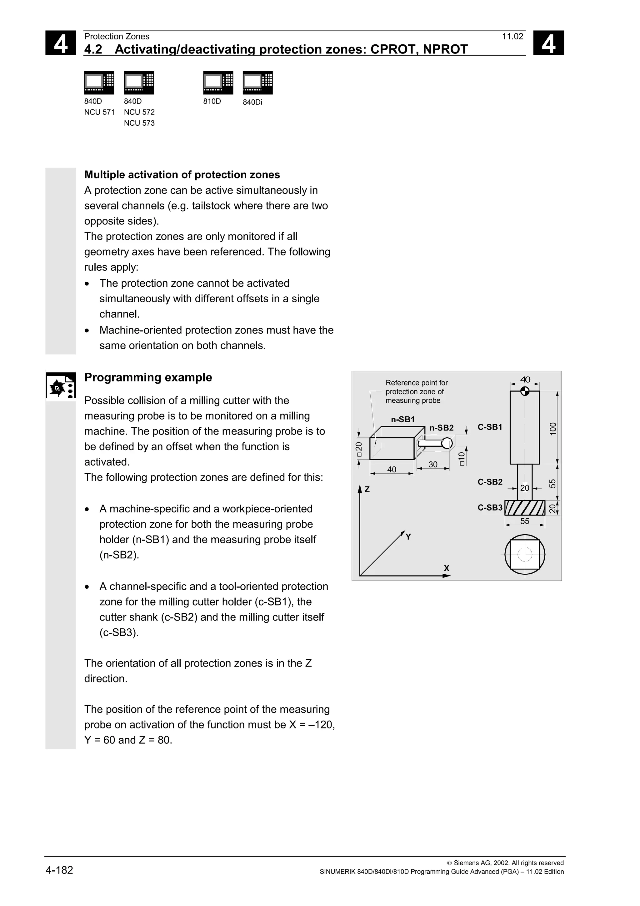
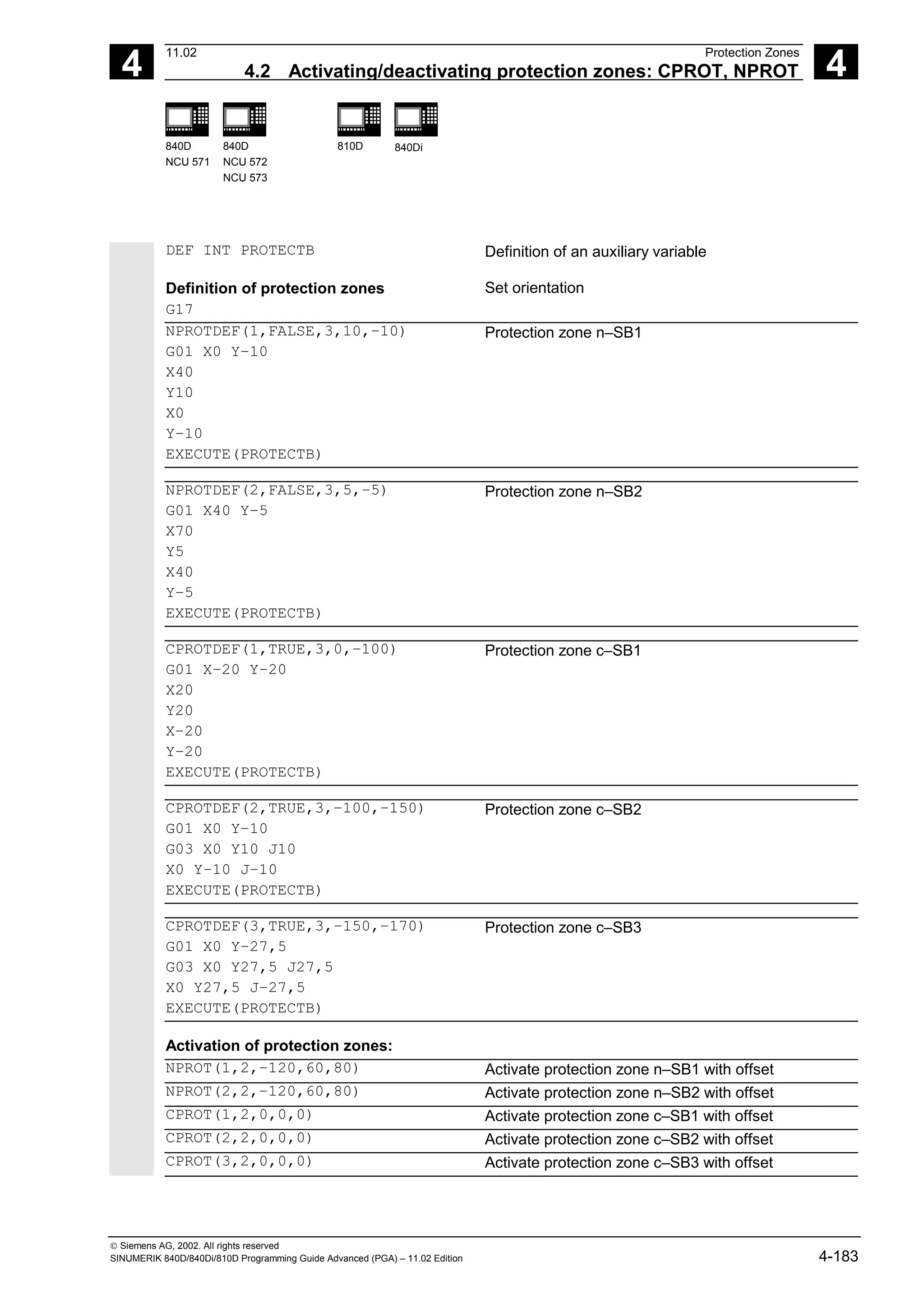

![5
Special Motion Commands 11.02
5.1 Approaching coded positions, CAC, CIC, CDC, CACP, CACN 5
840D
NCU 571
840D
NCU 572
NCU 573
810D 840Di
Siemens AG, 2002. All rights reserved
5-186 SINUMERIK 840D/840Di/810D Programming Guide Advanced (PGA) – 11.02 Edition
5.1 Approaching coded positions, CAC, CIC, CDC, CACP, CACN
Explanation of the commands
CAC(n) Approach coded positions absolutely
CIC(n) Approach coded position incrementally by n spaces in plus direction (+)
or in minus direction (–)
CDC(n) Approach coded position via shortest possible route (rotary axes only)
CACP(n) Approach coded position absolutely in positive direction (rotary axes only)
CACN(n) Approach coded position absolutely in negative direction (rotary axes only)
(n) Position numbers 1, 2, ... max. 60 positions for each axis
Sequence
You can enter a maximum of 60 (0 to 59) positions
in special position tables for two axes in machine
data.
For an example of a typical position table see
diagram.
Further details
If an axis is situated between two positions, it does
not traverse in response to an incremental position
command with CIC (...).
It is always advisable to program the first travel
command with an absolute position value.
6
1
2
3
4
3
2
1
0
0
0
27.3
1
40.7
2
112
3
112 mm
4
5
0
Table 1 (rotary axis)
0
45
1
90
...
...
7
2
315 deg.
7
0
Table 1 (linear axis)
Position number:
Position value:
Indexing axis:
Position number:
Position value:
Programming example
N10 FA[B]= 300 Feed for positioning axis B
N20 POS[B]= CAC (10) Approach coded position 10 (absolutely)
N30 POS[B]= CIC (-4) Travel 4 spaces back from the current
position](https://image.slidesharecdn.com/fadaladvancedprogrammingmanual-220505063253/75/Fadal-Advanced-Programming-Manual-pdf-186-2048.jpg)
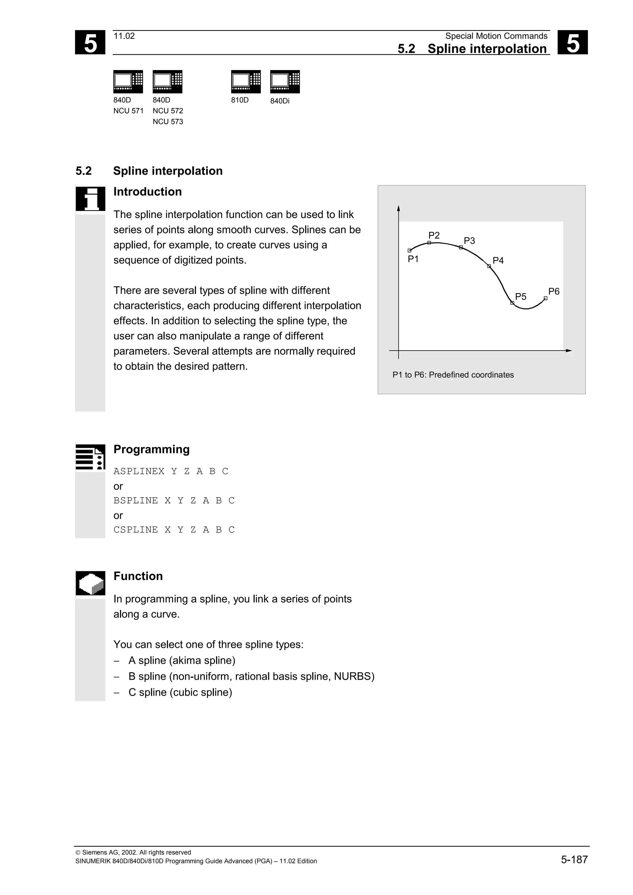
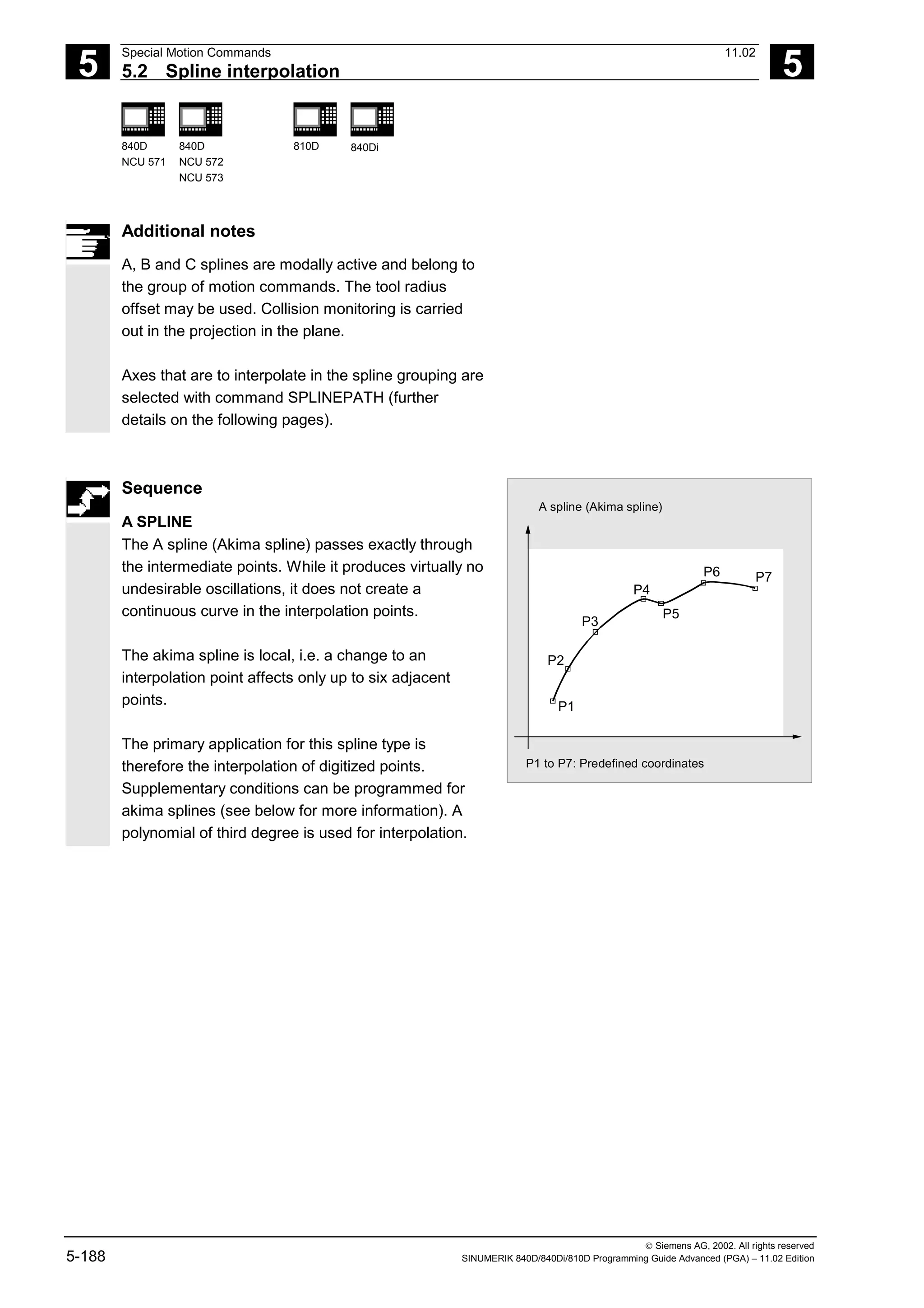
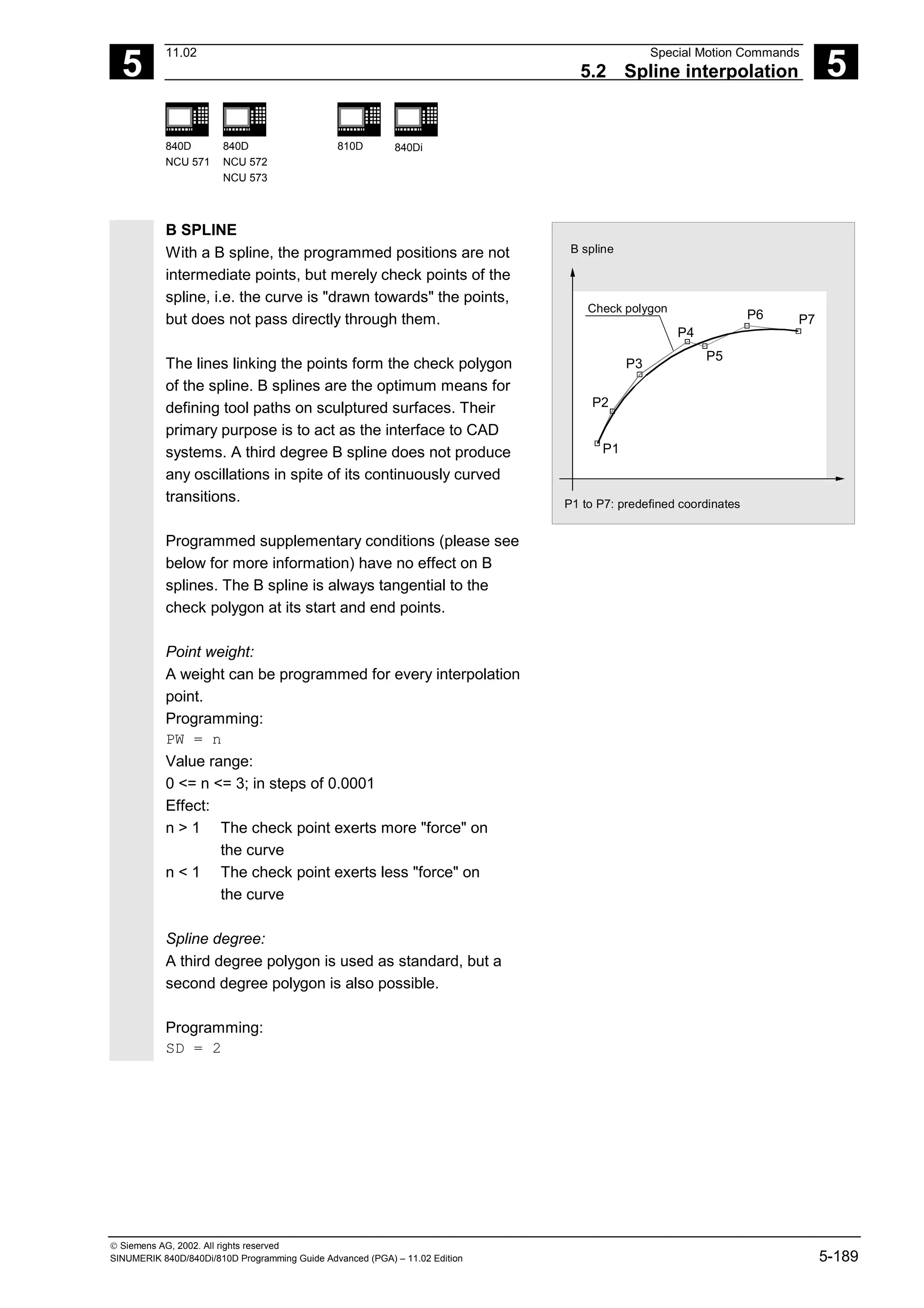
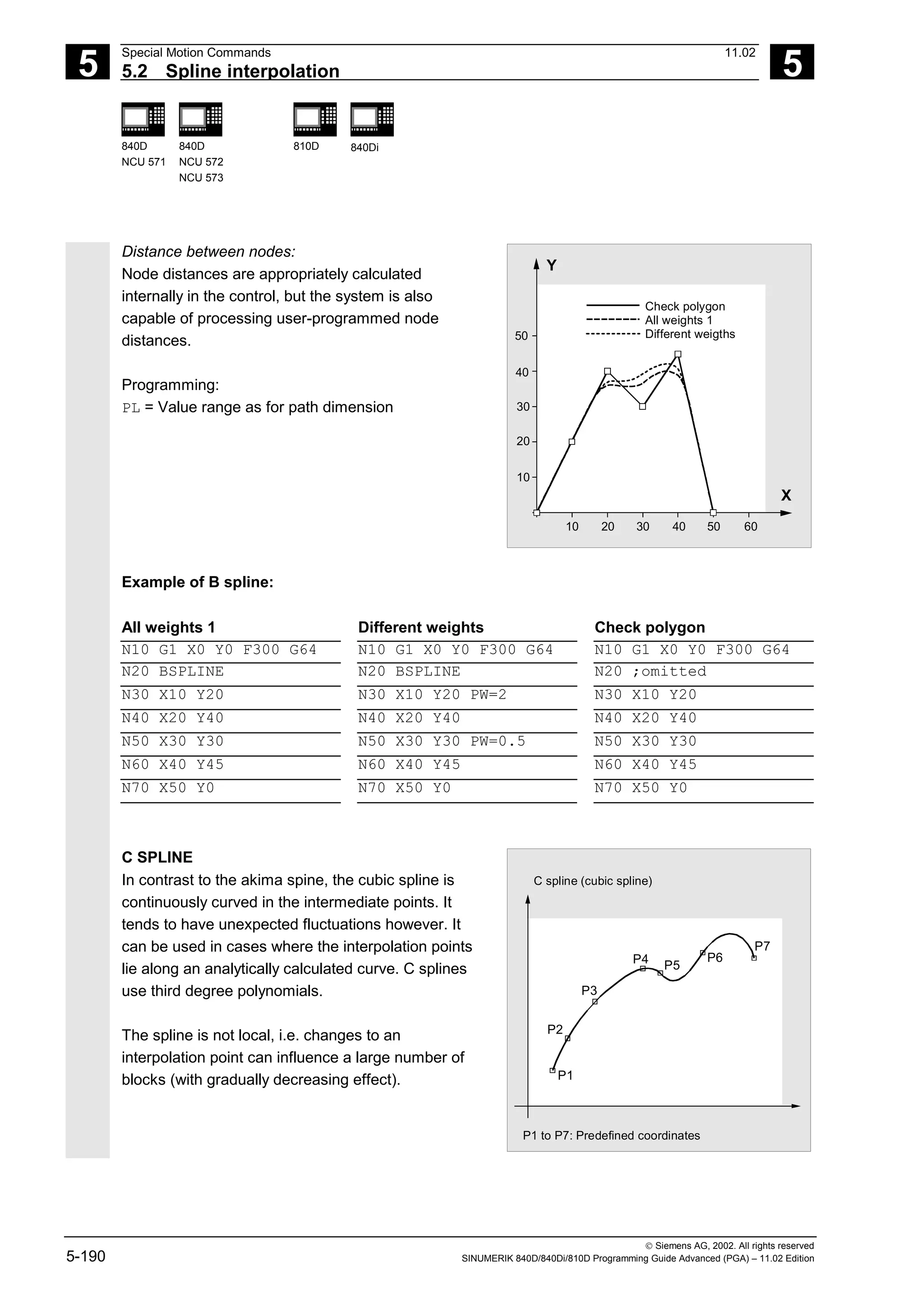
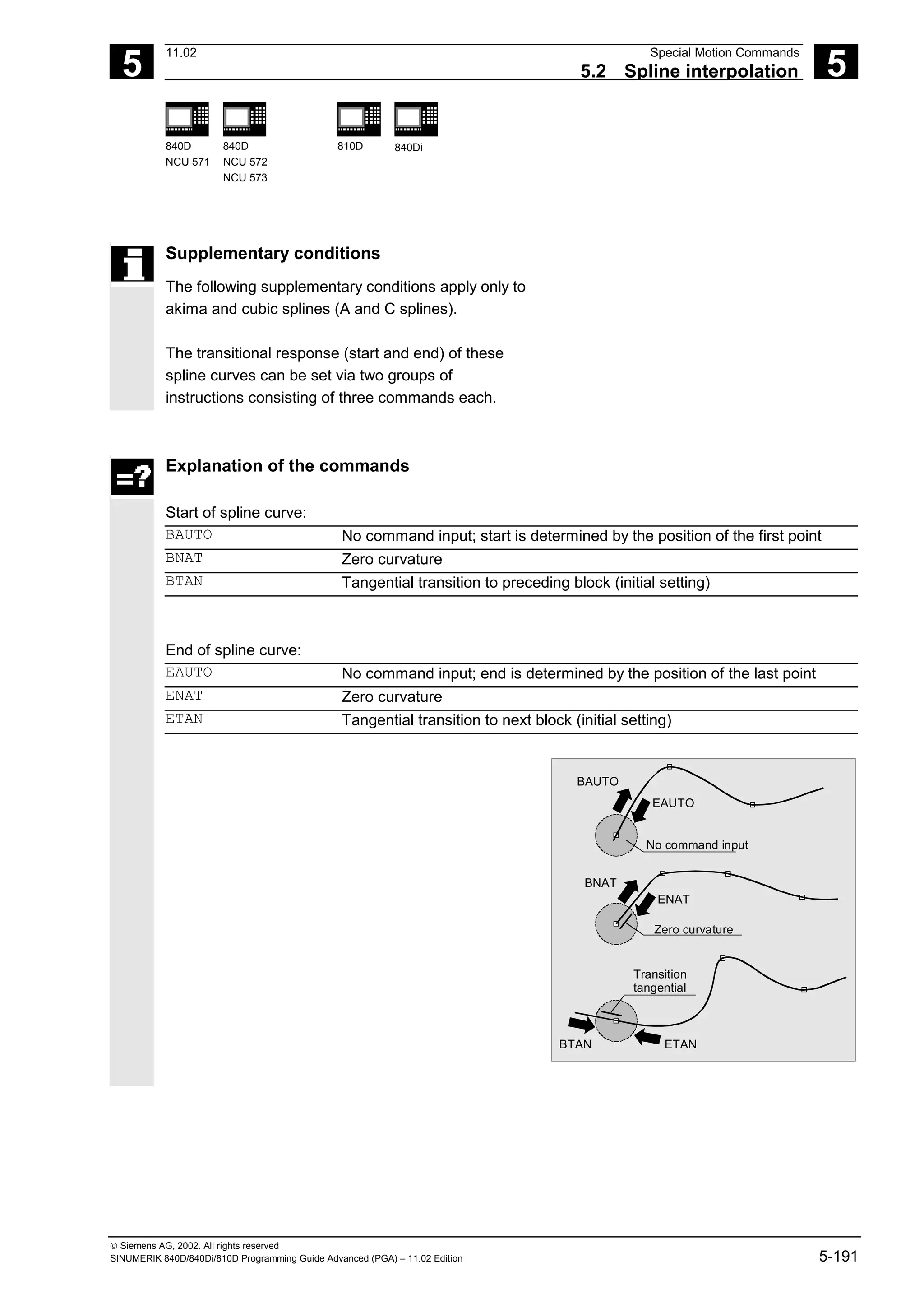
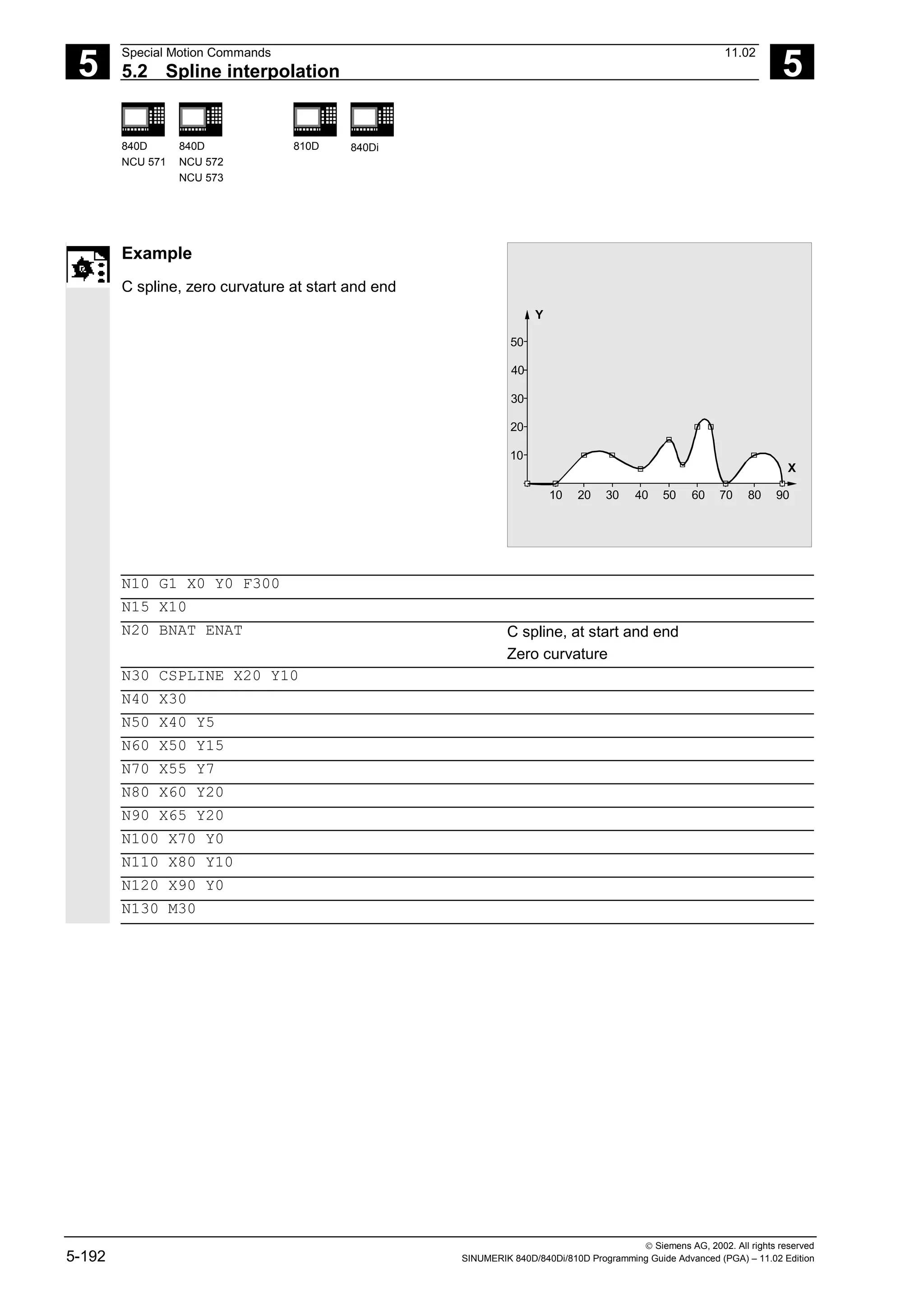
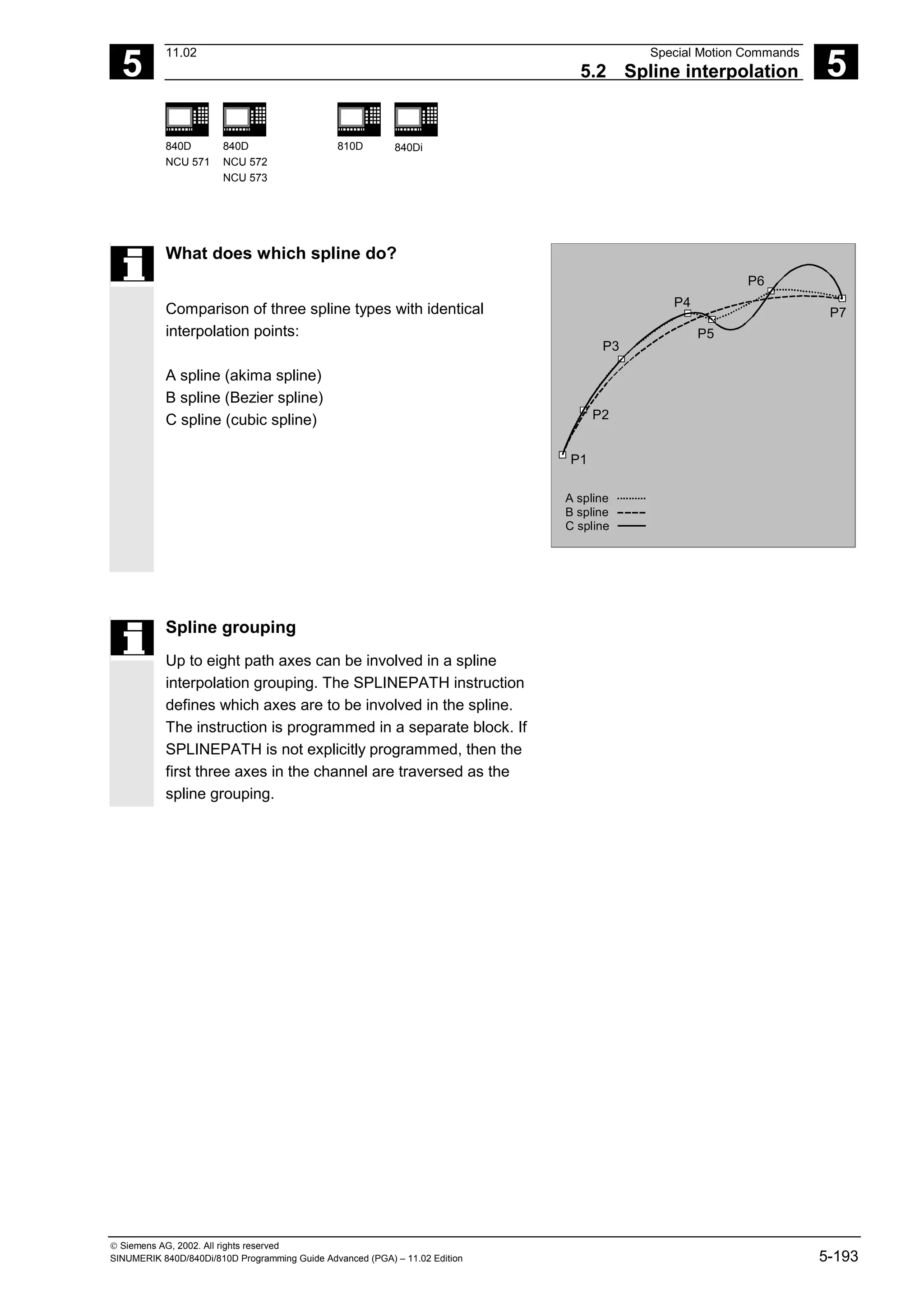
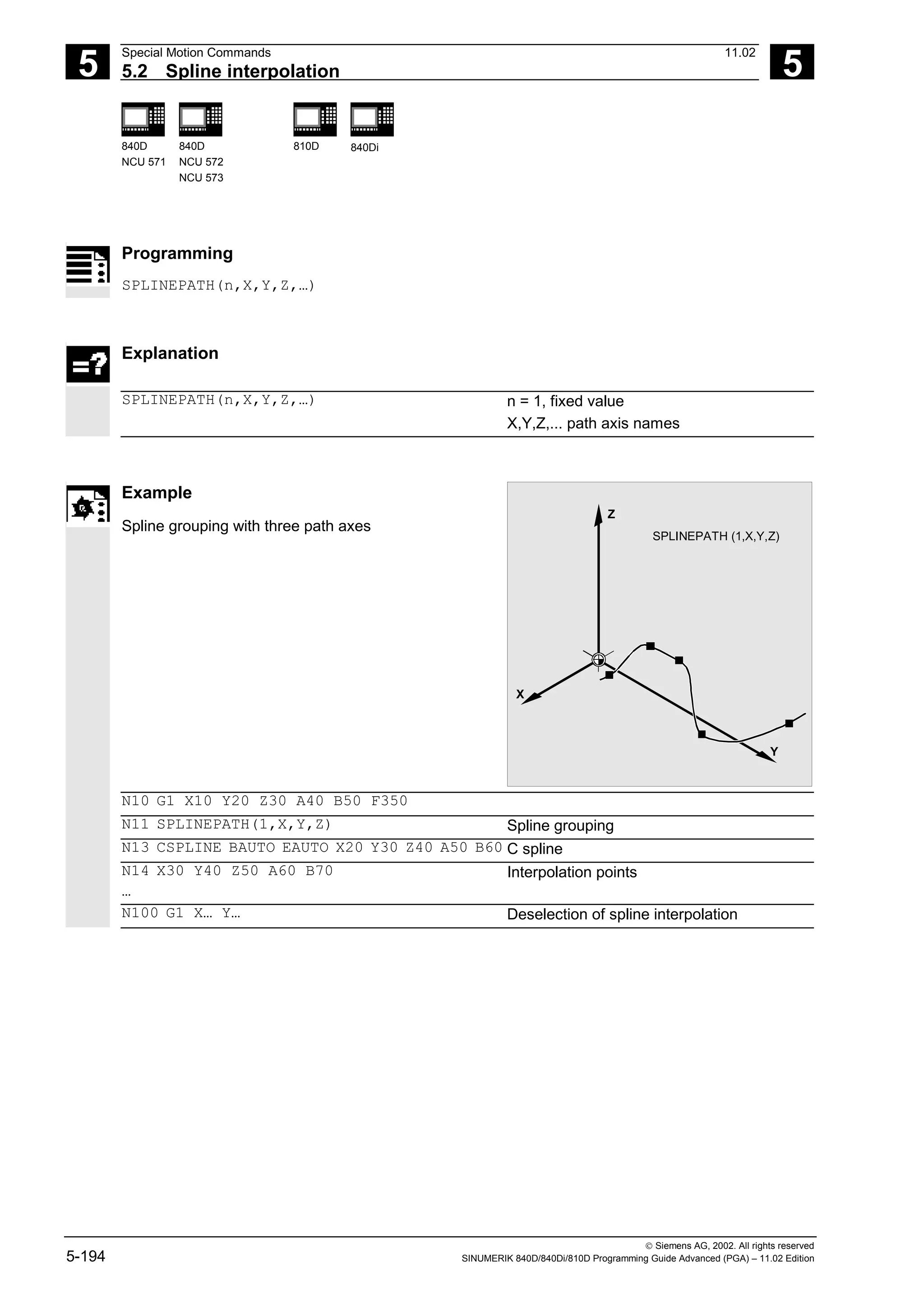
![5
Special Motion Commands 11.02
5.3 Compressor COMPON/COMPCURV/COMPCAD (SW 6.2) 5
840D
NCU 571
840D
NCU 572
NCU 573
810D 840Di
Siemens AG, 2002. All rights reserved
5-198 SINUMERIK 840D/840Di/810D Programming Guide Advanced (PGA) – 11.02 Edition
A large circle interpolation is performed under the
following conditions:
1. For MD 21104: ORI_IPO_WITH_G_CODE =
FALSE, if ORIWKS is active and orientation is
programmed as vector (with A3, B3, C3 or A2,
B2, C2).
2. For MD 21104: ORI_IPO_WITH_G_CODE =
TRUE, if ORIVECT or ORIPLANE are active.
Tool orientation can be programmed either as
direction vector or with rotary axis positions. If
one of the G–codes ORICONxx or ORICURVE
is active or if polynomials are programmed for
the orientation angle (PO[PHI] and PO[PSI]) a
large circle interpolation is not performed, i.e.,
blocks of this type are not compressed.
For 6-axis machines you can program the tool rotation
in addition to the tool orientation. You can program the
angle of rotation with the identifier THETA
(THETA=<...>).
NC blocks in which additional rotation is programmed,
can only be compressed if the angle of rotation changes
linear, meaning that you must not program a polynomial
with PO[THT]=(...) for the angle of rotation.
NC block structure in general:
N... X=<...> Y=<...> Z=<...> A3=<...>
B3=<...> C3=<...> THETA=<...> F=<...>
or
N... X=<...> Y=<...> Z=<...> A2=<...>
B2=<...> C2=<...> THETA=<...> F=<...>
If tool orientation is specified via rotary axis
positions, e.g. as:
N... X=<...> Y=<...> Z=<...> A=<...>
B=<...> THETA=<...> F=<...>
the compression will be performed in two different
ways, depending on whether a large circle
interpolation is performed or not. If large circle
interpolation is not performed, the compressed
orientation change is represented by axial
polynomials for the rotary axes.](https://image.slidesharecdn.com/fadaladvancedprogrammingmanual-220505063253/75/Fadal-Advanced-Programming-Manual-pdf-198-2048.jpg)
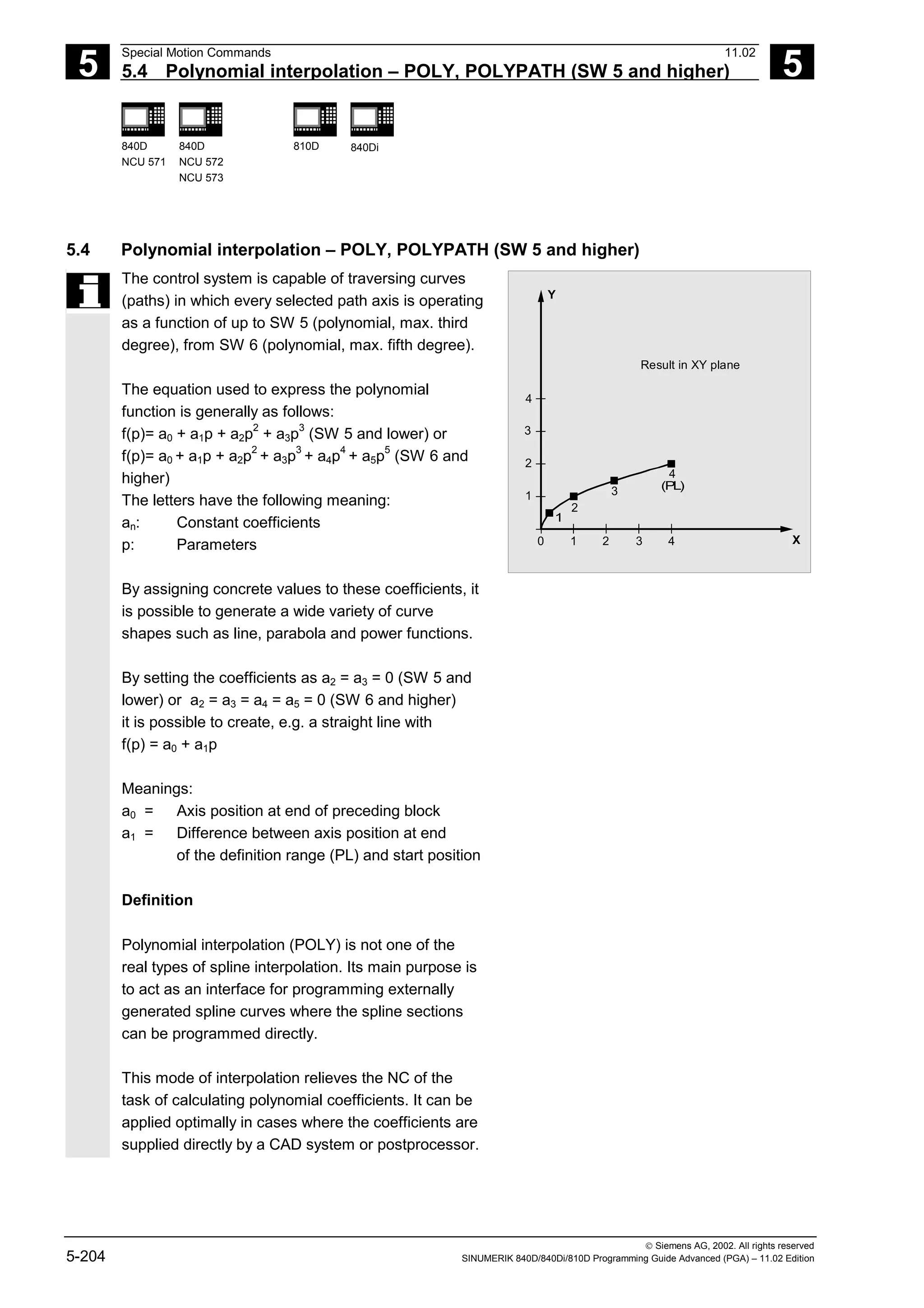
![5
11.02 Special Motion Commands
5.4 Polynomial interpolation – POLY, POLYPATH (SW 5 and higher) 5
840D
NCU 571
840D
NCU 572
NCU 573
810D 840Di
Siemens AG, 2002. All rights reserved
SINUMERIK 840D/840Di/810D Programming Guide Advanced (PGA) – 11.02 Edition 5-205
Polynomial interpolation belongs to the first G group
along with G0, G1, G2, G3, A spline, B spline and C
spline. If it is active, there is no need to program the
polynomial syntax: Axes that are programmed with
their name and end point only are traversed linearly
to their end point. If all axes are programmed in this
manner, the control system responds as if G1 were
programmed.
Polynomial interpolation is deactivated by another
command in the G group (e.g. G0, G1).
SW 5 and higher
Subprogram call POLYPATH:
With POLYPATH the polynomial interpolation can be
specified selectively for the following axis groups:
• POLYPATH ("AXES")
All path axes and special axes.
• POLYPATH ("VECT") orientation axes
(with orientation transformation).
As standard, the programmed polynomials are
interpreted as polynomial for both axis groups.
Examples:
POLYPATH ("VECT")
Only the orientation axes are selected for the
polynomial interpolation; all other axes are traversed
linearly.
POLPATH ( )
Deactivates the polynomial interpolation for all axes
Polynomial coefficient
The PO value (PO[]=) or ...=PO(...)specifies
all polynomial coefficients for an axis. Several
values, separated by commas, are specified
according to the degree of the polynomial. Different
polynomial degrees can be programmed for different
axes within one block.](https://image.slidesharecdn.com/fadaladvancedprogrammingmanual-220505063253/75/Fadal-Advanced-Programming-Manual-pdf-205-2048.jpg)
![5
Special Motion Commands 11.02
5.4 Polynomial interpolation – POLY, POLYPATH (SW 5 and higher) 5
840D
NCU 571
840D
NCU 572
NCU 573
810D 840Di
Siemens AG, 2002. All rights reserved
5-206 SINUMERIK 840D/840Di/810D Programming Guide Advanced (PGA) – 11.02 Edition
Supplementary conditions
SW 5 and lower
• Polynomials for geometry axes/special path axes
can only be programmed if either G0/G1 or POLY is
active. Therefore, with circular interpolation it is not
possible to traverse additional axes via polynomials.
As standard, polynomials can only be programmed
with PO[...] if the G code POLY is active.
SW 5 and higher
• It is possible to program polynomials without the G
code POLY being active. In this case, however, the
programmed polynomials are not interpolated;
instead the respective programmed endpoint of each
axis is approached linearly (G1).
The polynomial interpolation is then activated by
programming POLY.
• Also, if G code POLY is active, with the predefined
subprogram POLYPATH (...), you can select which
axes are to be interpolated with polynomial.
SW 6 and higher
• Coefficients a4 and a5 are only supported by SW
6 and higher.
• New polynomial syntax with PO
The syntax used hitherto also remains valid
Example of applicable polynomial syntax
with PO
Polynomial syntax used hitherto
remains valid
New polynomial syntax (SW 6
and higher)
PO[axis identifier]=(.. , ..) Axis identifier=PO(.. , ..)
PO[PHI]=(.. , ..) PHI=PO(.. , ..)
PO[PSI]=(.. , ..) PSI=PO(.. , ..)
PO[THT]=(.. , ..) THT=PO(.. , ..)
PO[]=(.. , ..) PO(.. , ..)
PO[variable]=IC(.. , ..) variable=PO IC(.. , ..)](https://image.slidesharecdn.com/fadaladvancedprogrammingmanual-220505063253/75/Fadal-Advanced-Programming-Manual-pdf-206-2048.jpg)
![5
11.02 Special Motion Commands
5.4 Polynomial interpolation – POLY, POLYPATH (SW 5 and higher) 5
840D
NCU 571
840D
NCU 572
NCU 573
810D 840Di
Siemens AG, 2002. All rights reserved
SINUMERIK 840D/840Di/810D Programming Guide Advanced (PGA) – 11.02 Edition 5-207
Programming
POLY PO[X]=(xe,a2,a3) PO[Y]=(ye,b2,b3) PO[Z]=(ze,c2,c3) PL=n (SW 5 and lower)
POLYPATH ("AXES", "VECT")(SW 5 and higher)
Expansion to polynomials of the 5th degree and new polynomial syntax
(SW 6 and higher)
POLY X=PO(xe,a2,a3,a4,a5) Y=PO(ye,b2,b3,b4,b5) Z=PO(ze,c2,c3,c4,c5) PL=n
Explanation
POLY Activation of polynomial interpolation with
a block containing POLY.
POLYPATH Polynomial interpolation can be selected
for both the AXIS or VECT axis groups
PO[axis identifier/variable]=(…,…,…) End points and polynomial coefficients
X, Y, Z Axis name
xe, ye, ze Specification of end position for relevant
axis; value range as for path dimension
a2, a3, a4, a5 Coefficients a2, a3, a4, and a5 are written with
their value; range of values as for path
dimension. The last coefficient in each case
can be omitted if it equals zero.
PL Length of parameter interval over which the
polynomials are defined (definition range of
function f(p)). The interval always starts at 0.
p can be set to values between 0 and PL.
Theoretical value range for PL: 0.0001 ... 99
999.9999. The PL values applies to the
block in which it is programmed. PL=1 is
applied if no PL value is programmed.
Example
N10 G1 X… Y… Z… F600
N11 POLY PO[X]=(1,2.5,0.7) ->
-> PO[Y]=(0.3,1,3.2) PL=1.5
Polynomial interpolation ON
N12 PO[X]=(0,2.5,1.7) PO[Y]=(2.3,1.7) PL=3
…
N20 M8 H126 …
N25 X70 PO[Y]=(9.3,1,7.67) PL=5 Mixed settings for axes
N27 PO[X]=(10.2.5) PO[Y]=(2.3) No PL value programmed; PL=1 applies
N30 G1 X… Y… Z. Polynomial interpolation OFF
…](https://image.slidesharecdn.com/fadaladvancedprogrammingmanual-220505063253/75/Fadal-Advanced-Programming-Manual-pdf-207-2048.jpg)
![5
Special Motion Commands 11.02
5.4 Polynomial interpolation – POLY, POLYPATH (SW 5 and higher) 5
840D
NCU 571
840D
NCU 572
NCU 573
810D 840Di
Siemens AG, 2002. All rights reserved
5-208 SINUMERIK 840D/840Di/810D Programming Guide Advanced (PGA) – 11.02 Edition
Example of a curve in the X/Y plane
p
Y
1
2
p
X
1
0 1 2 3 (PL)
2
3
4
4
End point 2
End point 4
Example:
N9 X0 Y0 G90
N10 POLY PO[Y]=
(2) PO[X]
(4.0.25) PL=4
N9 X0 Y0 G90 F100
N10 POLY PO[Y]=(2) PO[X]=(4,0.25) PL=4
X
Y
0
1
1
2
2
3
3
4
(P
L)
1
2
3
4
4
Result in XY plane](https://image.slidesharecdn.com/fadaladvancedprogrammingmanual-220505063253/75/Fadal-Advanced-Programming-Manual-pdf-208-2048.jpg)
![5
11.02 Special Motion Commands
5.4 Polynomial interpolation – POLY, POLYPATH (SW 5 and higher) 5
840D
NCU 571
840D
NCU 572
NCU 573
810D 840Di
Siemens AG, 2002. All rights reserved
SINUMERIK 840D/840Di/810D Programming Guide Advanced (PGA) – 11.02 Edition 5-209
Special case denominator polynomial
Command PO[]=(...) can be used to program a
common denominator polynomial for the geometry
axes (without specification of axes names), i.e. the
motion of the geometry axes is then interpolated as
the quotient of two polynomials.
With this programming option, it is possible to
represent forms such as conics (circle, ellipse,
parabola, hyperbola) exactly.
Example
POLY G90 X10 Y0 F100 Geometry axes traverse linearly to
position X10, Y0
PO[X]=(0,–10) PO[Y]=(10) PO[]=(2,1) Geometry axes traverse along quadrant to
X0, Y10
The constant coefficient (a0) of the denominator
polynomial is always assumed to be 1, the specified
end point is not dependent on G90/G91.
The result obtained from the above example is as
follows:
X(p)=10(1–p2
)/(1+p2
) and Y(p)=20p/(1+p2
)
where 0<=p<=1
As a result of the programmed start points, end
points, coefficient a2 and PL=1, the intermediate
values are as follows:
Numerator (X)=10+0*p–10p2
Numerator (Y)=0+20*p+0*p2
Denominator = 1+2*p+1*p2
X
10
Y](https://image.slidesharecdn.com/fadaladvancedprogrammingmanual-220505063253/75/Fadal-Advanced-Programming-Manual-pdf-209-2048.jpg)
![5
Special Motion Commands 11.02
5.4 Polynomial interpolation – POLY, POLYPATH (SW 5 and higher) 5
840D
NCU 571
840D
NCU 572
NCU 573
810D 840Di
Siemens AG, 2002. All rights reserved
5-210 SINUMERIK 840D/840Di/810D Programming Guide Advanced (PGA) – 11.02 Edition
An alarm is output if a denominator polynomial with
zeros is programmed within the interval [0,PL] when
polynomial interpolation is active. Denominator
polynomials have no effect on the motion of special
axes.
Additional notes
Tool radius compensation can be activated with
G41, G42 in conjunction with polynomial
interpolation and can be applied in the same way as
in linear or circular interpolation modes.](https://image.slidesharecdn.com/fadaladvancedprogrammingmanual-220505063253/75/Fadal-Advanced-Programming-Manual-pdf-210-2048.jpg)
![5
Special Motion Commands 11.02
5.5 Settable path reference, SPATH, UPATH (SW 4.3 and higher) 5
840D
NCU 571
840D
NCU 572
NCU 573
810D 840Di
Siemens AG, 2002. All rights reserved
5-212 SINUMERIK 840D/840Di/810D Programming Guide Advanced (PGA) – 11.02 Edition
Therefore, for the axes not contained in FGROUP
there are two ways to follow the path:
1. Either they travel synchronized with path S (SPATH)
2. or synchronized with curve parameter U of the
FGROUP axes (UPATH).
Both types of path interpolation are used in different
applications and can be switched via G codes SPATH
and UPATH.
UPATH and SPATH also determine the relationship of
the F word polynomial (FPOLY, FCUB, FLIN) with the
path movement.
Example
The example below shows a square with
20mm side lengths and corners rounded with G643.
The maximum deviations from the exact contour are
defined for each axis by the machine data
MD 33100: COMPRESS_POS_TOL[...].
N10 G1 X… Y… Z… F500
N20 G643 Block-internal corner rounding with G643
N30 XO Y0
N40 X20 Y0 20mm edge length for axes
N50 X20 Y20
N60 X0 Y20
N70 X0 Y0
N100 M30
Supplementary conditions
The path reference set is of no importance with
• linear and circular interpolation,
• in thread blocks and
• if all path axes are contained in FGROUP.](https://image.slidesharecdn.com/fadaladvancedprogrammingmanual-220505063253/75/Fadal-Advanced-Programming-Manual-pdf-212-2048.jpg)
![5
11.02 Special Motion Commands
5.5 Settable path reference, SPATH, UPATH (SW 4.3 and higher) 5
840D
NCU 571
840D
NCU 572
NCU 573
810D 840Di
Siemens AG, 2002. All rights reserved
SINUMERIK 840D/840Di/810D Programming Guide Advanced (PGA) – 11.02 Edition 5-213
Activation
The path reference for the axes that are not contained
in FGROUP is set via the two language commands
SPATH and UPATH contained in the 45th G code
group. The commands are modal. If SPATH is active,
the axes are traversed synchronized with the path; if
UPATH is active, traversal is synchronized with the
curve parameter.
Programming example
The following program example shows the difference
between both types of motion control. Both times the
default setting FGROUP(X,Y,Z) is active.
X
10
A
10
SPATH:
A(X)=X
X
10
A
10
UPATH:
A(X)=SQRT(X)
Different geometry relationships between
axes with SPATH and UPATH
N10 G1 X0 A0 F1000 SPATH
N20 POLY PO[X]=(10, 10) A10
or
N10 G1 X0 F1000 UPATH
N20 POLY PO[X]=(10, 10) A10
In block N20, path S of the FGROUP axes is
dependent on the square of curve parameter U.
Therefore, different positions arise for synchronized
axis A along the path of X, according to whether
SPATH or UPATH is active:](https://image.slidesharecdn.com/fadaladvancedprogrammingmanual-220505063253/75/Fadal-Advanced-Programming-Manual-pdf-213-2048.jpg)
![5
Special Motion Commands 11.02
5.5 Settable path reference, SPATH, UPATH (SW 4.3 and higher) 5
840D
NCU 571
840D
NCU 572
NCU 573
810D 840Di
Siemens AG, 2002. All rights reserved
5-214 SINUMERIK 840D/840Di/810D Programming Guide Advanced (PGA) – 11.02 Edition
Control response at power ON, mode change,
Reset, block search, REPOS
After Reset the G code defined via MD 20150:
GCODE_RESET_VALUES [44] is active (45th G code
group).
The basic setting value for the type of rounding is set
in MD 20150: GCODE_RESET_VALUES [9] (10th G
code group).
Machine/option data
The G code group value active after Reset is
determined via machine data MD 20150:
GCODE_RESET_VALUES [44].
In order to maintain compatibility with existing
installations, SPATH is set as default value.
The basic setting value for the type of rounding is set
in MD 20150: GCODE_RESET_VALUES [9] (10th G
code group).
Axial machine data MD 33100:
COMPRESS_POS_TOL has been expanded in SW
4.3 and higher: It contains the tolerances for the
compressor function and for rounding with G642.](https://image.slidesharecdn.com/fadaladvancedprogrammingmanual-220505063253/75/Fadal-Advanced-Programming-Manual-pdf-214-2048.jpg)
![5
11.02 Special Motion Commands
5.6 Measurements with touch trigger probe, MEAS, MEAW 5
840D
NCU 571
840D
NCU 572
NCU 573
810D
CCU 2
840Di
Siemens AG, 2002. All rights reserved
SINUMERIK 840D/840Di/810D Programming Guide Advanced (PGA) – 11.02 Edition 5-215
5.6 Measurements with touch trigger probe, MEAS, MEAW
Programming
MEAS=±1
MEAS=±2
G… X… Y… Z…
G… X… Y… Z…
(+1/+2 measurement with deletion of
distance-to-go and rising edge)
(–1/–2 measurement with deletion of
distance-to-go and falling edge)
MEAW=±1
MEAW=±2
G… X… Y… Z…
G… X… Y… Z…
(+1/+2 measurement without deletion of
distance-to-go and rising edge)
(–1/–2 measurement without deletion of
distance-to-go and falling edge)
Explanation of the commands
MEAS=±1 Measurement with probe 1 at measuring input 1
MEAS=±2* Measurement with probe 2 at measuring input 2
MEAW=±1 Measurement with probe 1 at measuring input 1
MEAW=±2* Measurement with probe 2 at measuring input 2
*Max. of two inputs depending on configuration level
Sequence
The positions coinciding with the switching edge of
the probe are acquired for all axes programmed in
the NC block and written for each specific axis to the
appropriate memory cell. A maximum of 2 probes
can be installed.
Measurement result
The measurement result is available under the
following variables for these axes:
• Under $AA_MM[axis] in the machine coordinate
system
• Under $AA_MW[axis] in the workpiece
coordinate system
No internal preprocessing stop is generated when
these variables are read.
A preprocessing stop must be programmed with
STOPRE at the appropriate position in the program.
The system will otherwise read false values.
Z
X](https://image.slidesharecdn.com/fadaladvancedprogrammingmanual-220505063253/75/Fadal-Advanced-Programming-Manual-pdf-215-2048.jpg)
![5
Special Motion Commands 11.02
5.6 Measurements with touch trigger probe, MEAS, MEAW 5
840D
NCU 571
840D
NCU 572
NCU 573
810D
CCU 2
840Di
Siemens AG, 2002. All rights reserved
5-216 SINUMERIK 840D/840Di/810D Programming Guide Advanced (PGA) – 11.02 Edition
Measuring job status
Status variable $AC_MEA[n] (n= number of probe)
can be scanned if the switching state of the touch
trigger probe needs to be evaluated in the program:
0 Measuring job not performed
1 Measuring job successfully completed
(probe has switched state)
If the probe is deflected during program execution,
this variable is set to 1. At the beginning of a
measurement block, the variable is automatically set
to correspond to the starting state of the probe.
Programming measuring blocks, MEAS, MEAW
When command MEAS is programmed in conjunction
with an interpolation mode, actual positions on the
workpiece are approached and measured values
recorded simultaneously. The distance-to-go between
the actual and setpoint positions is deleted.
The MEAW function is employed in the case of
special measuring tasks where a programmed
position must always be approached.
MEAS and MEAW are programmed in a block with
motion commands. The feeds and interpolation
types (G0, G1, ...) must be selected to suit the
measuring task in hand; this also applies to the
number of axes.
Example:
N10 MEAS=1 G1 F1000 X100 Y730 Z40
Measurement block with probe at first measuring
input and linear interpolation. A preprocessing stop
is automatically generated.](https://image.slidesharecdn.com/fadaladvancedprogrammingmanual-220505063253/75/Fadal-Advanced-Programming-Manual-pdf-216-2048.jpg)
![5
Special Motion Commands 11.02
5.7 Extended measuring function MEASA, MEAWA, MEAC 5
840D
NCU 571
840D
NCU 572
NCU 573
810D
CCU 2
840Di
Siemens AG, 2002. All rights reserved
5-218 SINUMERIK 840D/840Di/810D Programming Guide Advanced (PGA) – 11.02 Edition
5.7 Extended measuring function MEASA, MEAWA, MEAC
(SW 4 and higher, option)
Programming
MEASA[axis]=(mode, TE1,…, TE 4)
Measurement with delete distance-to-go
MEAWA[Achse]=(Modus, TE 1,…, TE 4)
Measurement without delete distance-to-go
MEAC[axis]=(mode, measurement memory,
TE 1,...TE4)
Continuous measurement without
deletion of distance-to-go
Explanation
Axis Name of channel axis used for measurement
Mode Two-digit setting for operating mode consisting of Measuring mode (ones
decade) and
0 Cancel measurement task
1 Mode 1: Up to 4 trigger events that can be activated
simultaneously
2 Mode 2: Up to 4 trigger events that can be activated sequentially
3 Mode 3: Up to 4 trigger events that can be activated sequentially
However, no monitoring of trigger event 1
On START (alarms 21700/21703 are suppressed)
Note: Mode 3 not possible with MEAC
Measuring system (tens' decade)
0 or no setting: Active measuring system
1 Measuring system 1
2 Measuring system 2
3 Both measuring systems
TE 1…4 Trigger event
1 Rising edge, probe 1
-1 Falling edge, probe 1
2 Rising edge, probe 2
-2 Falling edge, probe 2
Measurement
memory
Number of FIFO (circulating storage)](https://image.slidesharecdn.com/fadaladvancedprogrammingmanual-220505063253/75/Fadal-Advanced-Programming-Manual-pdf-218-2048.jpg)
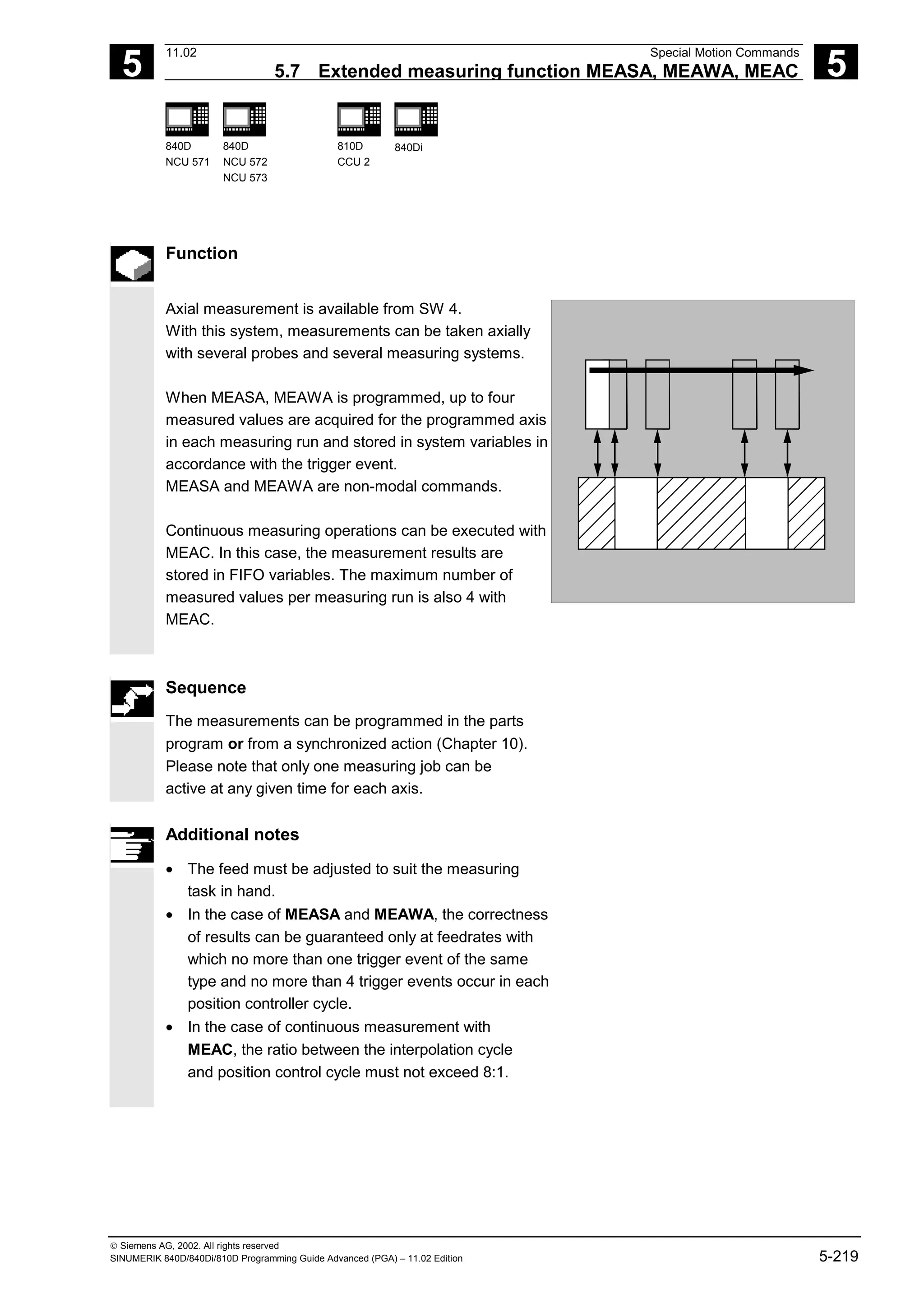
![5
11.02 Special Motion Commands
5.7 Extended measuring function MEASA, MEAWA, MEAC 5
840D
NCU 571
840D
NCU 572
NCU 573
810D
CCU 2
840Di
Siemens AG, 2002. All rights reserved
SINUMERIK 840D/840Di/810D Programming Guide Advanced (PGA) – 11.02 Edition 5-221
Measurement with and without delete
distance-to-go
When command MEASA is programmed, the
distance-to-go is not deleted until all required
measured values have been recorded.
The MEAWA function is employed in the case of
special measuring tasks where a programmed
position must always be approached.
MEASA and MEAWA can be programmed in the
same block.
If MEASA/MEAWA is programmed with MEAS/MEAW
in the same block, an error message is output.
t
V
TE1 TE2 TE3 TE4
Programmed path
Distance
to go
• MEASA cannot be programmed in synchronized
actions.
As an alternative, MEAWA plus the deletion of
distance-to-go can be programmed as a
synchronized action.
• If the measuring job with MEAWA is started from
the synchronized actions, the measured values
will only be available in machine coordinates.
Measurement results for MEASA, MEAWA
The results of measurements are available under the
following system variables:
• In machine coordinate system:
$AA_MM1[axis] Measured value of programmed measuring system on trigger event 1
… ...
$AA_MM4[axis] Measured value of programmed measuring system on trigger event 4
• In workpiece coordinate system:
$AA_WM1[axis] Measured value of programmed measuring system on trigger event 1
… ...
$AA_WM4[axis] Measured value of programmed measuring system on trigger event 4](https://image.slidesharecdn.com/fadaladvancedprogrammingmanual-220505063253/75/Fadal-Advanced-Programming-Manual-pdf-221-2048.jpg)
![5
Special Motion Commands 11.02
5.7 Extended measuring function MEASA, MEAWA, MEAC 5
840D
NCU 571
840D
NCU 572
NCU 573
810D
CCU 2
840Di
Siemens AG, 2002. All rights reserved
5-222 SINUMERIK 840D/840Di/810D Programming Guide Advanced (PGA) – 11.02 Edition
Additional notes
No internal preprocessing stop is generated when these
variables are read.
A preprocessing stop must be programmed with
STOPRE (Section 15.1) at the appropriate position.
False values will otherwise be read in.
If axial measurement is to be started for a geometry
axis, the same measuring job must be programmed
explicitly for all remaining geometry axes.
The same applies to axes involved in a transformation.
Example:
N10 MEASA[Z]=(1,1) MEASA[Y]=(1,1)
MEASA[X]=(1,1) G0 Z100;
or
N10 MEASA[Z]=(1,1) POS[Z]=100
Measuring job with two measuring systems
If a measuring job is executed by two measuring
systems, each of the two possible trigger events of both
measuring systems of the relevant axis is acquired. The
assignment of the reserved variables is therefore
preset:
$AA_MM1[axis] or $AA_MW1[axis] Measured value of measuring system 1
on trigger event 1
$AA_MM2[axis] or $AA_MW2[axis] Measured value of measuring system 2
on trigger event 1
$AA_MM3[axis] or $AA_MW3[axis] Measured value of measuring system 2
on trigger event 1
$AA_MM4[axis] or $AA_MW4[axis] Measured value of measuring system 2
on trigger event
Measuring probe status can be read via
$A_PROBE[n]
n=Probe
1==Probe deflected
0==Probe not deflected](https://image.slidesharecdn.com/fadaladvancedprogrammingmanual-220505063253/75/Fadal-Advanced-Programming-Manual-pdf-222-2048.jpg)
![5
11.02 Special Motion Commands
5.7 Extended measuring function MEASA, MEAWA, MEAC 5
840D
NCU 571
840D
NCU 572
NCU 573
810D
CCU 2
840Di
Siemens AG, 2002. All rights reserved
SINUMERIK 840D/840Di/810D Programming Guide Advanced (PGA) – 11.02 Edition 5-223
Measuring job status for MEASA, MEAWA
If the probe switching state needs to be evaluated in
the program, then the measuring job status can be
interrogated via $AC_MEA[n], with n = number of
probe.
Once all the trigger events of probe "n" that are
programmed in a block have occurred, this variable
switches to the "1" stage. Its value is otherwise 0.
If measuring is started from synchronized actions,
$AC_MEA is not updated. In this case, new PLC status
signals DB(31-48) DBB62 bit 3 or the equivalent
variable $AA_MEAACT[“Axis“] must be interrogated.
Meaning: $AA_MEAACT==1: Measuring active
$AA_MEAACT==0: Measuring not active
References: /FB/ M5, Measurement
Continuous measurement MEAC
The measured values for MEAC are available in the
machine coordinate system and stored in the
programmed FIFO[n] memory (circulating memory).
If two probes are configured for the measurement,
the measured values of the second probe are stored
separately in the FIFO[n+1] memory configured
especially for this purpose (defined in machine data).
The FIFO memory is a circulating memory in which
measured values are written to $AC_FIFO variables
according to the circulation principle.
References: /PGA/ Chapter 10, Synchronized Actions
Additional notes
• FIFO contents can be read only once from the
circulating storage. If these measured data are to be
used multiply, they must be buffered in user data.
• If the number of measured values for the FIFO
memory exceeds the maximum value defined in
machine data, the measurement is automatically
terminated.
• An endless measuring process can be implemented
by reading out measured values cyclically. In this
case, data must be read out at the same frequency
as new measured values are read in.](https://image.slidesharecdn.com/fadaladvancedprogrammingmanual-220505063253/75/Fadal-Advanced-Programming-Manual-pdf-223-2048.jpg)
![5
Special Motion Commands 11.02
5.7 Extended measuring function MEASA, MEAWA, MEAC 5
840D
NCU 571
840D
NCU 572
NCU 573
810D
CCU 2
840Di
Siemens AG, 2002. All rights reserved
5-224 SINUMERIK 840D/840Di/810D Programming Guide Advanced (PGA) – 11.02 Edition
Programming example
Measurement with delete distance-to-go in mode 1
(evaluation in chronological sequence)
a) with one measuring system
...
N100 MEASA[X] = (1,1,-1) G01 X100 F100 Measurement in mode 1 with active
measuring system. Wait for measuring
signal with rising/falling edge from probe
1 on travel path to X = 100.
N110 STOPRE Preprocessing stop
N120 IF $AC_MEA[1] == FALSE gotof END Check success of measurement.
N130 R10 = $AA_MM1[X] Store measured value acquired on first
programmed trigger event (rising edge)
N140 R11 = $AA_MM2[X] Store measured value acquired on
second programmed trigger event (falling
edge)
N150 END:
Programming example
b) with two measuring systems
...
N200 MEASA[X] = (31,1-1) G01 X100 F100 Measurement in mode 1 with both
measuring systems. Wait for measuring
signal with rising/falling edge from probe
1 on travel path to X = 100.
N210 STOPRE Preprocessing stop
N220 IF $AC_MEA[1] == FALSE gotof END Check success of measurement.
N230 R10 = $AA_MM1[X] Store measured value of measuring
system 1 on rising edge
N240 R11 = $AA_MM2[X] Store measured value of measuring
system 2 on rising edge
N250 R12 = $AA_MM3[X] Store measured value of measuring
system 1 on falling edge](https://image.slidesharecdn.com/fadaladvancedprogrammingmanual-220505063253/75/Fadal-Advanced-Programming-Manual-pdf-224-2048.jpg)
![5
11.02 Special Motion Commands
5.7 Extended measuring function MEASA, MEAWA, MEAC 5
840D
NCU 571
840D
NCU 572
NCU 573
810D
CCU 2
840Di
Siemens AG, 2002. All rights reserved
SINUMERIK 840D/840Di/810D Programming Guide Advanced (PGA) – 11.02 Edition 5-225
N260 R13 = $AA_MM4[X] Store measured value of measuring
system 2 on falling edge
N270 END:
Measurement with delete distance-to-go in mode 2
(evaluation in programmed sequence)
...
N100 MEASA[X] = (2,1,-1,2,-2) G01 X100
F100
Measurement in mode 2 with active
measuring system. Wait for measuring
signal in the following order: Rising edge
of probe 1, falling edge of probe 1, rising
edge of probe 2, falling edge of probe 2,
on travel path to X = 100.
N110 STOPRE Preprocessing stop
N120 IF $AC_MEA[1] == FALSE gotof Check success of measurement with
probe 1
PROBE2
N130 R10 = $AA_MM1[X] Store measured value acquired on first
programmed trigger event (rising edge
probe 1)
N140 R11 = $AA_MM2[X] Store measured value acquired on
second programmed trigger event (rising
edge probe 1)
N150 PROBE2:
N160 IF $AC_MEA[2] == FALSE gotof END Check success of measurement with
probe 2
N170 R12 = $AA_MM3[X] Store measured value acquired on third
programmed trigger event (rising edge
probe 2)
N180 R13 = $AA_MM4[X] Store measured value acquired on fourth
programmed trigger event (rising edge
probe 2)
N190 END:](https://image.slidesharecdn.com/fadaladvancedprogrammingmanual-220505063253/75/Fadal-Advanced-Programming-Manual-pdf-225-2048.jpg)
![5
Special Motion Commands 11.02
5.7 Extended measuring function MEASA, MEAWA, MEAC 5
840D
NCU 571
840D
NCU 572
NCU 573
810D
CCU 2
840Di
Siemens AG, 2002. All rights reserved
5-226 SINUMERIK 840D/840Di/810D Programming Guide Advanced (PGA) – 11.02 Edition
Programming example
Continuous measurement in mode 1
(evaluation in chronological sequence)
Measurement of up to 100 measured values
...
N110 DEF REAL MEASVALUE[100]
N120 DEF INT loop = 0
N130 MEAC[X] = (1,1,-1) G01 X1000 F100 Measure in mode 1 with active measuring
system, store measured values under
$AC_FIFO1, wait for measuring signal with
falling edge from probe 1 on travel path to
X = 1000.
N135 STOPRE
N140 MEAC[X] = (0) Terminate measurement when axis
position is reached.
N150 R1 = $AC_FIFO1[4] Store number of accumulated measured
values in parameter R1.
N160 FOR loop = 0 TO R1-1
N170 MEASVALUE[loop] = $AC_FIFO1[0] Read measured values from $AC_FIFO1
and store.
N180 ENDFOR
Measurement with delete distance-to-go after ten
measured values
...
(x) Delete distance-to-go
N20 MEAC[x]=(1,1,1,-1) G01 X100 F500
N30 MEAC[X]=(0)
N40 R1 = $AC_FIFO1[4] Number of measured values
...](https://image.slidesharecdn.com/fadaladvancedprogrammingmanual-220505063253/75/Fadal-Advanced-Programming-Manual-pdf-226-2048.jpg)
![5
11.02 Special Motion Commands
5.7 Extended measuring function MEASA, MEAWA, MEAC 5
840D
NCU 571
840D
NCU 572
NCU 573
810D
CCU 2
840Di
Siemens AG, 2002. All rights reserved
SINUMERIK 840D/840Di/810D Programming Guide Advanced (PGA) – 11.02 Edition 5-227
The following programming errors are detected and indicated
appropriately:
• MEASA/MEAWA is programmed with MEAS/MEAW in the same
block
Example:
N01 MEAS=1 MEASA[X]=(1,1) G01 F100 POS[X]=100
• MEASA/MEAWA with number of parameters <2 or >5
Example:
N01 MEAWA[X]=(1) G01 F100 POS[X]=100
• MEASA/MEAWA with trigger event not equal to 1/ -1/ 2/ -2
Example:
N01 MEASA[B]=(1,1,3) B100
• MEASA/MEAWA with invalid mode
Example:
N01 MEAWA[B]=(4,1) B100
• MEASA/MEAWA with trigger event programmed twice
Example:
N01 MEASA[B]=(1,1,-1,2,-1) B100
• MEASA/MEAWA and missing GEO axis
Example:
N01 MEASA[X]=(1,1) MEASA[Y]=(1,1) G01 X50 Y50 Z50 F100
• Inconsistent measuring job with GEO axes
Example:
N01 MEASA[X]=(1,1) MEASA[Y]=(1,1) MEASA[Z]=(1,1,2) G01
X50 Y50 Z50 F100
GEO axis X/Y/Z](https://image.slidesharecdn.com/fadaladvancedprogrammingmanual-220505063253/75/Fadal-Advanced-Programming-Manual-pdf-227-2048.jpg)
![5
11.02 Special Motion Commands
5.9 Programmable motion end criterion (SW 5.1 and higher) 5
840D
NCU 571
840D
NCU 572
NCU 573
810D
CCU 2
840Di
Siemens AG, 2002. All rights reserved
SINUMERIK 840D/840Di/810D Programming Guide Advanced (PGA) – 11.02 Edition 5-229
5.9 Programmable motion end criterion (SW 5.1 and higher)
Programming
FINEA[<axis>]
COARSEA[<axis>]
IPOENDA[<axis>]
IPOBRKA(<axis>[, [<value as percentage>]]) Multiple specifications are possible
ADISPOSA(<axis>, [<int>][,[<real>]]) Multiple specifications are possible
Explanation of the commands
FINEA Motion end when "Exact stop FINE" reached
COARSEA Motion end when "Exact stop COARSE" reached
IPOENDA Motion end when "Interpolator-Stop" reached
IPOBRKA Block change in braking ramp possible (SW 6.2 and higher)
ADISPOSA Size of tolerance window for end of motion criterion (SW 6.4 and higher)
Axis Channel axis name (X, Y, ....)
Value as
percentage
When relative to the braking ramp of the block change should be as %
Int Mode 0: tolerance window not active
1: tolerance window relative to setpoint position
2: tolerance window relative to actual position
Real Size of tolerance window. This value is entered in setting data 43610:
ADISPOSA_VALUE synchronized with the main run
Function
Similar to the block change criterion for continuous-
path interpolation (G601, G602 and G603), the end
of motion criterion can be programmed in a parts
program for single axis interpolation or in
synchronized action for the command/PLC axes.
Depending on the end of motion criterion set, parts
program blocks or technology cycle blocks with
single axis motion take different times to complete.
The same applies for PLC positioning statements
via FC15/ 16/ 18.](https://image.slidesharecdn.com/fadaladvancedprogrammingmanual-220505063253/75/Fadal-Advanced-Programming-Manual-pdf-229-2048.jpg)
![5
Special Motion Commands 11.02
5.9 Programmable motion end criterion (SW 5.1 and higher) 5
840D
NCU 571
840D
NCU 572
NCU 573
810D
CCU 2
840Di
Siemens AG, 2002. All rights reserved
5-230 SINUMERIK 840D/840Di/810D Programming Guide Advanced (PGA) – 11.02 Edition
System variable $AA_MOTEND
The default motion end characteristic can be requested
via system variable $AA_MOTEND[<axis>].
• $AA_MOTEND[<axis>] = 1 Motion end with "Exact stop fine"
• $AA_MOTEND[<axis>] = 2 Motion end with "Exact stop coarse"
• $AA_MOTEND[<axis>] = 3 End of motion with "IPO-Stop".
• $AA_MOTEND[<axis>] = 4 (SW 6.2 and
higher)
Block change criterion braking ramp
of axis motion
• $AA_MOTEND[<axis>] = 5 (SW 6.4 and
higher)
Block change in braking ramp with toler-
ance window relative to "setpoint position".
• $AA_MOTEND[<axis>] = 6 (SW 6.4 and
higher)
Block change in braking ramp with toler-
ance window relative to "actual position".
Additional notes
The last programmed value is retained after RESET.
References: /FB1/, V1 Feedrates
SW 6.2 and higher
Block change criterion in braking ramp
The percentage value is entered in SD 43600:
IPOBRAKE_BLOCK_EXCHANGE synchronized with
the main run. If no value is specified, the current
value of this setting data is effective.
The range is adjustable from 0% to 100%.
Additional tolerance window for IPOBRKA
SW 6.4 and higher, an additional block change
criterion tolerance window can be selected as well
as the existing block change criterion in the braking
ramp. Release only occurs when the axis
• as before, reaches the preset %-value of its
braking ramp and
• SW 6.4 and higher, its current actual or setpoint
position is no further than a tolerance from the
end of the axis in the block.
For more information on the block change criterion
of the positioning axes, please refer to:
References: /FB2/, P2 positioning axes
/PG/, Feed rate control and spindle motion](https://image.slidesharecdn.com/fadaladvancedprogrammingmanual-220505063253/75/Fadal-Advanced-Programming-Manual-pdf-230-2048.jpg)
![5
11.02 Special Motion Commands
5.9 Programmable motion end criterion (SW 5.1 and higher) 5
840D
NCU 571
840D
NCU 572
NCU 573
810D
CCU 2
840Di
Siemens AG, 2002. All rights reserved
SINUMERIK 840D/840Di/810D Programming Guide Advanced (PGA) – 11.02 Edition 5-231
Programming examples
...
N110 G01 POS[X]=100 FA[X]=1000 ACC[X]=90 IPOENDA[X]
Traversing to position X100 with a path velocity of 1000rpm, an acceleration value of
90% and end of motion on reaching the interpolator stop
...
N120 EVERY $A_IN[1] DO POS[X]=50 FA[X]=2000 ACC[X]=140 IPOENDA[X]
Traversing to position X50 when input 1 is active, with a path velocity of 2000rpm, an
acceleration value of 140% and end of motion on reaching the interpolator stop
...
Block change criterion braking ramp in the parts program
; default setting active
N40 POS[X]=100
; block change occurs when X-axis reaches position 100 and fine exact stop
N20 IPOBRKA(X,100) ; activate block change criterion braking ramp
N30 POS[X]=200 ; block change occurs as soon as X-axis starts to brake
N40 POS[X]=250
; the x-axis does not brake at position 200 but continues to position 250,
; as soon as the X-axis starts to brake, the block change occurs
N50 POS[X]=0 ; the X-axis brakes and moves back to position 0
; the block change occurs at position 0 and fine exact stop
N60 X10F100
N70 M30
...
Block change criterion braking ramp within synchronized actions
Within the technology cycle:
FINEA ; end of motion criterion fine exact stop
POS[X]=100 ; technology cycle block change occurs when X-axis
; has reached position 100 and fine exact stop
IPOBRKA(X,100) ; activate block change criterion braking ramp
POS[X]=100 ; POS[X]=100; technology cycle block change occurs,
; as soon as the X-axis starts to brake
POS[X]=250 ; the X-axis does not brake at position 200 but continues
; to position 250, as soon as the X-axis starts to brake
; the block change in the technology cycle occurs
POS[X]=250 ; the X-axis brakes and moves back to position 0
; the block change occurs at position 0 and fine exact stop
M17](https://image.slidesharecdn.com/fadaladvancedprogrammingmanual-220505063253/75/Fadal-Advanced-Programming-Manual-pdf-231-2048.jpg)
![5
Special Motion Commands 11.02
5.10 Programmable servo parameter block (SW 5.1 and higher) 5
840D
NCU 571
840D
NCU 572
NCU 573
810D
CCU 2
840Di
Siemens AG, 2002. All rights reserved
5-232 SINUMERIK 840D/840Di/810D Programming Guide Advanced (PGA) – 11.02 Edition
5.10 Programmable servo parameter block (SW 5.1 and higher)
Programming
SCPARA[<Axis>]= <Value>
Explanation of the commands
SCPARA Define parameter block
Axis Channel axis name (X, Y, ...)
Value Desired parameter block (1<= value <=6)
Function
Using SCPARA, it is possible to program the parameter
block (consisting of MDs) in the parts program and in
synchronized actions (previously only via PLC).
DB3n DBB9 Bit3
To prevent conflicts between the PLC–user request
and NC–user request, a further bit is defined on the
PLC–>NCK interface:
DB3n DBB9 Bit3 "Parameter block definition locked
through SCPARA".
In the case of a locked parameter block for SCPARA,
an error message is produced if programmed.
The current parameter block can be polled using the
system variables $AA_SCPAR[<Axis>].](https://image.slidesharecdn.com/fadaladvancedprogrammingmanual-220505063253/75/Fadal-Advanced-Programming-Manual-pdf-232-2048.jpg)
![5
11.02 Special Motion Commands
5.10 Programmable servo parameter block (SW 5.1 and higher) 5
840D
NCU 571
840D
NCU 572
NCU 573
810D
CCU 2
840Di
Siemens AG, 2002. All rights reserved
SINUMERIK 840D/840Di/810D Programming Guide Advanced (PGA) – 11.02 Edition 5-233
Additional notes
• Up to SW 5.1, the servo-parameter block can be
specified only by the PLC (DB3n DBB9 Bit0–2).
For G33, G331 and G332, the most suitable
parameter block is selected by the control.
• If the servo parameter block is to be changed
both in a parts program and in a synchronized
action and the PLC, the PLC application
program must be extended.
• References: /FB1/V1 Feedrates
Programming example
...
N110 SCPARA[X]= 3 The 3rd parameter block is selected for axis X
...
n](https://image.slidesharecdn.com/fadaladvancedprogrammingmanual-220505063253/75/Fadal-Advanced-Programming-Manual-pdf-233-2048.jpg)
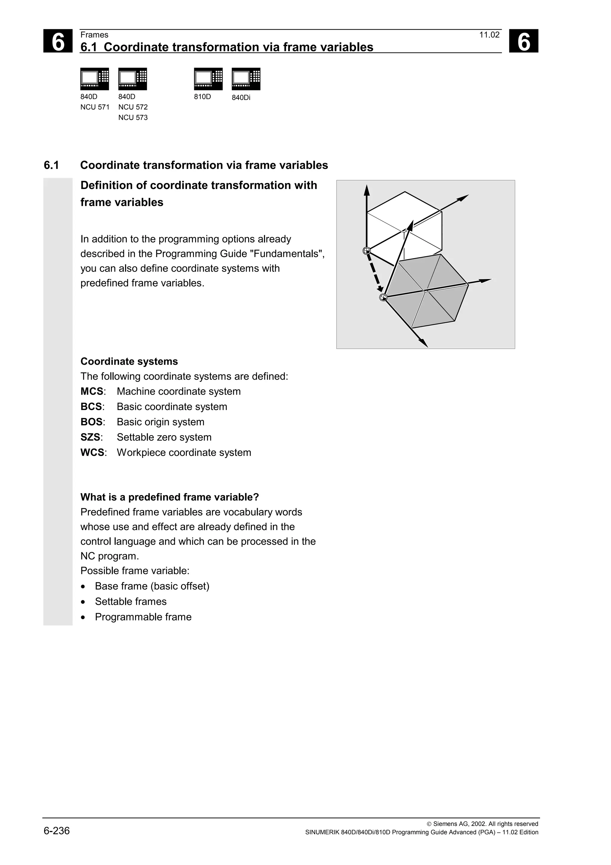
![6
11.02 Frames
6.1 Coordinate transformation via frame variables 6
840D
NCU 571
840D
NCU 572
NCU 573
810D 840Di
Siemens AG, 2002. All rights reserved
SINUMERIK 840D/840Di/810D Programming Guide Advanced (PGA) – 11.02 Edition 6-237
Frame variable/frame relationship
A coordinate transformation can be activated by
assigning the value of a frame to a frame variable.
Example: $P_PFRAME=CTRANS(X,10)
Frame variable:
$P_PFRAME means: current programmable frame.
Frame:
CTRANS(X,10)means: programmable zero offset of
X axis by 10 mm.
YBCS
X
BCS
YBOS
X
BOS
YSZS
XSZS
YWCS
X
WCS
$P_BFRAME, $P_UBFR
$P_IFRAME, $P_UIFR[..]
$P_PFRAME
Reading out actual values
The current actual values of the coordinate system
can be read out via predefined variables in the parts
program:
$AA_IM[axis] Read actual value in MCS
$AA_IB[axis] Read actual value in BCS
$AA_IBN[axis] Read actual value in BOS
$AA_IEN[axis] Read actual value in SZS
$AA_IW[axis] Read actual value in WCS
Overview of predefined variables
$P_BFRAME
Current base frame variable that establishes the
reference between the basic coordinate system
(BCS) and the basic origin system (BOS).
For the base frame described via $P_UBFR to be
immediately active in the program, either
• you have to program a G500, G54...G599, or
• you have to describe $P_BFRAME with
$P_UBFR,
ZBCS
XBCS
ZBOS
XBOS
$P_BFRAME, $P_UBFR](https://image.slidesharecdn.com/fadaladvancedprogrammingmanual-220505063253/75/Fadal-Advanced-Programming-Manual-pdf-237-2048.jpg)
![6
Frames 11.02
6.1 Coordinate transformation via frame variables 6
840D
NCU 571
840D
NCU 572
NCU 573
810D 840Di
Siemens AG, 2002. All rights reserved
6-238 SINUMERIK 840D/840Di/810D Programming Guide Advanced (PGA) – 11.02 Edition
$P_IFRAME
Current, settable frame variable that establishes the
reference between the basic origin system (BOS)
and the settable zero system (SZS).
$P_IFRAME corresponds to P_UIFR[$P_IFRNUM]
After G54 is programmed, for example, $P_IFRAME
contains the translation, rotation, scaling and
mirroring defined by G54.
ZBOS
YBOS
X BOS
SZS
SZS
SZS
Z
X
Y
$P_PFRAME
Current, programmable frame variable that
establishes the reference between the settable zero
system (SZS) and the workpiece coordinate system
(WCS).
$P_PFRAME contains the frame resulting from the
programming of TRANS/ATRANS, ROT/AROT,
SCALE/ASCALE, MIRROR/AMIRROR or the
assignment of CTRANS, CROT, CMIRROR,
CSCALE to the programmable FRAME.
ZBOS
Y
X BOS
Z
X
Z
SZS
SZS
WCS
WCS
WCS
X
SZS
BOS
Y
Y
$P_ACTFRAME
Current total frame resulting from chaining of the
current base frame variable $P_BFRAME, the current
settable frame variable $P_IFRAME and the current
programmable frame variable $P_PFRAME.
$P_ACTFRAME describes the currently valid
workpiece zero.
If $P_IFRAME, $P_BFRAME or $P_PFRAME are
changed, $P_ACTFRAME is recalculated.
$P_ACTFRAME corresponds to
$P_BFRAME:$P_IFRAME:$P_PFRAME
ZBOS
Y
X BOS
Z
Z
Y
X
Y
X
SZS
SZS
WCS
WCS
SZS
BOS
WCS
X BCS
ZBCS](https://image.slidesharecdn.com/fadaladvancedprogrammingmanual-220505063253/75/Fadal-Advanced-Programming-Manual-pdf-238-2048.jpg)
![6
11.02 Frames
6.1 Coordinate transformation via frame variables 6
840D
NCU 571
840D
NCU 572
NCU 573
810D 840Di
Siemens AG, 2002. All rights reserved
SINUMERIK 840D/840Di/810D Programming Guide Advanced (PGA) – 11.02 Edition 6-239
$P_IFRAME :
$P_BFRAME :
$P_ACTFRAME
$P_UBFR $P_UIFR[n]
$P_PFRAME
=
Activated via
G500, G54...G599
Entered
via MMC
Entered via program, e.g.
$P_UBFR=CTRANS(X,10)
Entered
via MMC
Entered via program, e.g.
$P_UIFR[n]=CTRANS(X,10)
Entered via program, e.g.
$P_BFRAME=CTRANS(X,10)
Entered via program, e.g.
$P_IFRAME=CTRANS(X,10)
Entered via program, e.g.
$P_PFRAME=CTRANS(X,10)
or TRANS X10
Base frame and settable frame are effective
after Reset if MD 20110
RESET_MODE_MASK is set as follows:
Bit0=1, bit14=1 --> $P_UBFR (base frame)
effective
Bit0=1, bit5=1 --> $P_UIFR [$P_UIFRNUM]
(settable frame) effective
Predefined settable frames $P_UBFR
The base frame is programmed with $P_UBFR, but
it is not simultaneously active in the parts program.
The base frame programmed with $P_UBFR is
included in the calculation if
• Reset was activated and bits 0 and 14 are set in
MD RESET_MODE_MASK and
• instructions G500, G54...G599 were executed.
Predefined settable frames $P_UIFR[n]
The predefined frame variable $P_UIFR[n] can be
used to read or write the settable zero offsets G54 to
G599 from the parts program.
These variables produce a one-dimensional array of
type FRAME called $P_UIFR[n].
Assignment to G commands
Five predefined settable frames are set as standard
$P_UIFR[0]...$P_UIFR[4] or 5 G commands with
the same meaning – G500 and G54 to G57 – at
whose addresses values can be stored.](https://image.slidesharecdn.com/fadaladvancedprogrammingmanual-220505063253/75/Fadal-Advanced-Programming-Manual-pdf-239-2048.jpg)
![6
Frames 11.02
6.1 Coordinate transformation via frame variables 6
840D
NCU 571
840D
NCU 572
NCU 573
810D 840Di
Siemens AG, 2002. All rights reserved
6-240 SINUMERIK 840D/840Di/810D Programming Guide Advanced (PGA) – 11.02 Edition
$P_IFRAME=$P_UIFR[0] corresponds to G500
$P_IFRAME=$P_UIFR[1] corresponds to G54
$P_IFRAME=$P_UIFR[2] corresponds to G55
$P_IFRAME=$P_UIFR[3] corresponds to G56
$P_IFRAME=$P_UIFR[4] corresponds to G57
You can change the number of frames with machine
data:
$P_IFRAME=$P_UIFR[5] corresponds to G505
… … …
$P_IFRAME=$P_UIFR[99] corresponds to G599
This allows you to generate up to 100 coordinate
systems which can be called up globally in different
programs, for example, as zero point for various
fixtures.
Frame variables must be programmed in a separate
NC block in the NC program.
Exception: programming of a settable frame with
G54, G55, ...](https://image.slidesharecdn.com/fadaladvancedprogrammingmanual-220505063253/75/Fadal-Advanced-Programming-Manual-pdf-240-2048.jpg)
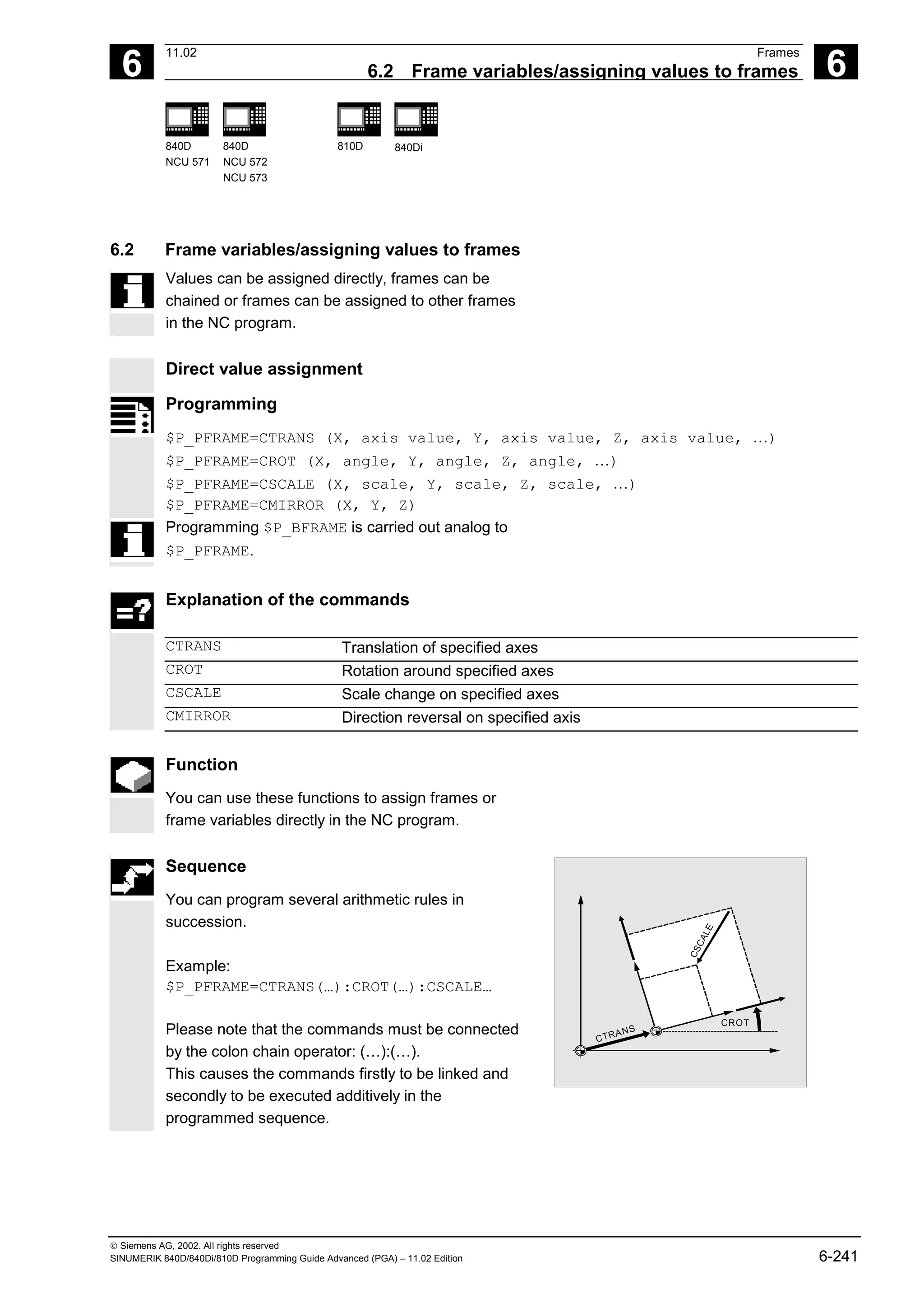
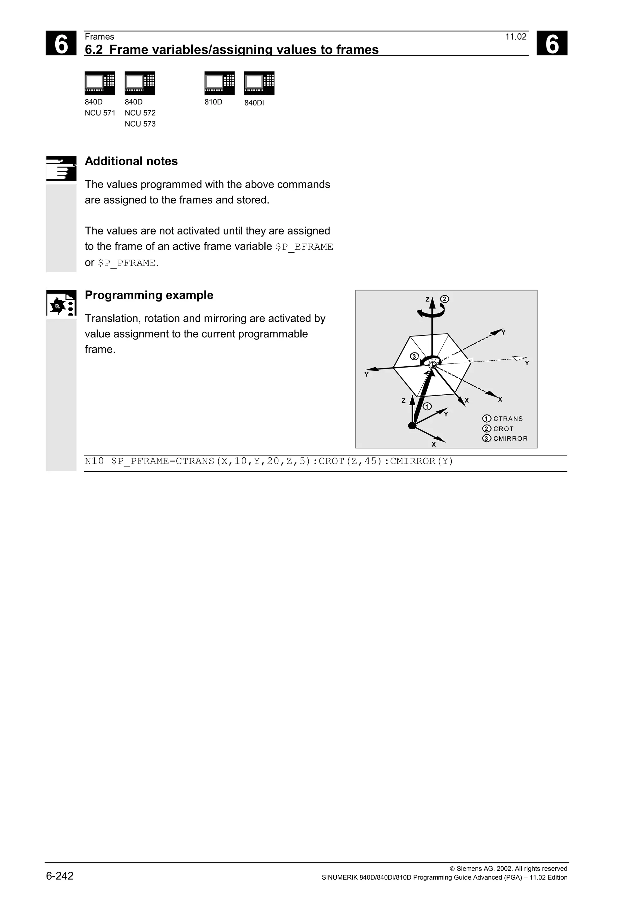
![6
11.02 Frames
6.2 Frame variables/assigning values to frames 6
840D
NCU 571
840D
NCU 572
NCU 573
810D 840Di
Siemens AG, 2002. All rights reserved
SINUMERIK 840D/840Di/810D Programming Guide Advanced (PGA) – 11.02 Edition 6-243
Reading and changing frame components
Programming (examples)
R10=$P_UIFR[$P_UIFRNUM, X, RT] Assign the angle of rotation RT around the X
axis from currently valid settable zero offset
$P_UIFRNUM to the variable R10.
R12=$P_UIFR[25, Z, TR] Assign the offset value TR in Z from the data
record of set frame no. 25 to the variable
R12.
R15=$P_PFRAME[Y, TR] Assign the offset value TR in Y of the current
programmable frame to the variable R15.
$P_PFRAME[X, TR]=25 Modify the offset value TR in X of the current
programmable frame. X25 applies
immediately.
Explanation of the commands
$P_UIFRNUM This command automatically establishes the reference to the currently
valid settable zero offset.
P_UIFR[n, …, …] Specify the frame number n to access the settable frame no. n.
TR
FI
RT
SC
MI
Specify the component to be read or modified:
TR translation, FI translation fine, RT rotation, SC scale change,
MI mirroring.
The corresponding axis is also specified (see examples).](https://image.slidesharecdn.com/fadaladvancedprogrammingmanual-220505063253/75/Fadal-Advanced-Programming-Manual-pdf-243-2048.jpg)
![6
Frames 11.02
6.2 Frame variables/assigning values to frames 6
840D
NCU 571
840D
NCU 572
NCU 573
810D 840Di
Siemens AG, 2002. All rights reserved
6-244 SINUMERIK 840D/840Di/810D Programming Guide Advanced (PGA) – 11.02 Edition
Function
This feature allows you to access individual data of
a frame, e.g. a specific offset value or angle of
rotation.
You can modify these values or assign them to
another variable.
Sequence
Calling frame
By specifying the system variable $P_UIFRNUM you
can access the current zero offset set with $P_UIFR
or G54, G55, ... ($P_UIFRNUM contains the number
of the currently set frame).
All other stored settable $P_UIFR frames are called
up by specifying the appropriate number
$P_UIFR[n].
For predefined frame variables and user-defined
frames, specify the name, e.g. $P_IFRAME.
Calling data
The axis name and the frame component of the
value you want to access or modify are written in
square brackets, e.g. [X, RT] or [Z, MI].](https://image.slidesharecdn.com/fadaladvancedprogrammingmanual-220505063253/75/Fadal-Advanced-Programming-Manual-pdf-244-2048.jpg)
![6
11.02 Frames
6.2 Frame variables/assigning values to frames 6
840D
NCU 571
840D
NCU 572
NCU 573
810D 840Di
Siemens AG, 2002. All rights reserved
SINUMERIK 840D/840Di/810D Programming Guide Advanced (PGA) – 11.02 Edition 6-245
Linking complete frames
A complete frame can be assigned to another frame.
Programming (examples)
DEF FRAME SETTING1
SETTING1=CTRANS(X,10)
$P_PFRAME=SETTING1
DEF FRAME SETTING4
SETTING4=$P_PFRAME
$P_PFRAME=SETTING4
Assign the values of the user frame
SETTING1 to the current programmable
frame.
The current programmable frame is
stored temporarily and can be recalled.
Additional notes
Value range for RT rotation
Rotation around 1st geometry axis: –180° to +180°
Rotation around 2nd geometry axis: –89.999° to +90°
Rotation around 3rd geometry axis: –180° to +180°
Frame chaining
Programming (examples)
$P_IFRAME=$P_UIFR[15]:$P_UIFR[16]
$P_UIFR[3]=$P_UIFR[4]:$P_UIFR[5]
$P_UIFR[15] contains, for example,
data for zero offsets. The data of
$P_UIFR[16], e.g. data for rotations,
are subsequently processed additively.
The settable frame 3 is created by
chaining the settable frames 4 and 5.](https://image.slidesharecdn.com/fadaladvancedprogrammingmanual-220505063253/75/Fadal-Advanced-Programming-Manual-pdf-245-2048.jpg)
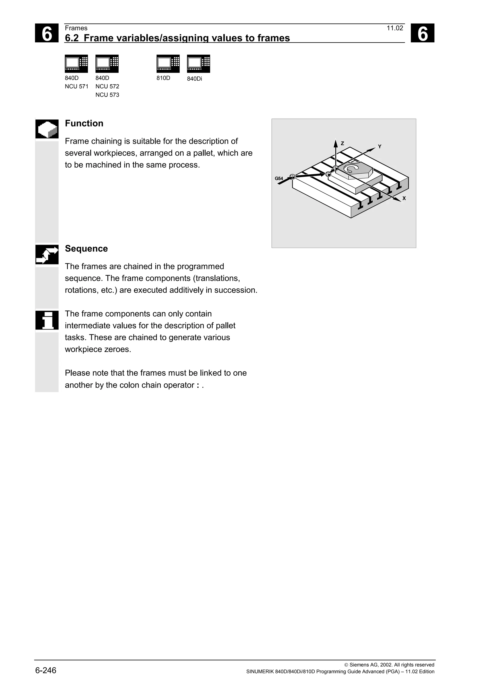
![6
Frames 11.02
6.3 Coarse/fine offset 6
840D
NCU 571
840D
NCU 572
NCU 573
810D 840Di
Siemens AG, 2002. All rights reserved
6-248 SINUMERIK 840D/840Di/810D Programming Guide Advanced (PGA) – 11.02 Edition
6.3 Coarse/fine offset
Function
Fine offset
A fine offset of the base frames and of all other
settable frames can be programmed with command
CFINE(X, ..,Y, ...).
Coarse offset
The coarse offset is defined with CTRANS(...).
Coarse and fine offset add up to the total offset.
Coarse offset
Fine offset
Rotation
Scaling
Mirroring
Frame structure with fine offset
Programming
$P_UBFR=CTRANS(x, 10) : CFINE(x, 0.1) : CROT(x, 45) ;chaining offset, fine
offset and rotation
$P_UIFR[1]=CFINE(x, 0.5, y, 1.0, z, 0.1) ;the total frame is overwritten with
CFINE, incl. coarse offset.
Access to the individual components of the fine offset is
achieved through component specification FI.
Programming
DEF REAL FINEX ;Definition of variable FINEX
FINEX=$P_UIFR[$P_UIFRNUM, x, FI] ;Readout the fine offset via variable FINEX
FINEX=$P_UIFR[3, X, FI] ;Readout the fine offset of X axis in the 3rd frame via
variable FINEX
Fine offset can only take place if MD 18600:
MM_FRAME_FINE_TRANS=1.
A fine offset changed via operator input is only active
after the corresponding frame is activated, i.e.
activation is conducted via G500, G54...G599. An
activated fine offset of a frame is active for as long
as the frame is active.](https://image.slidesharecdn.com/fadaladvancedprogrammingmanual-220505063253/75/Fadal-Advanced-Programming-Manual-pdf-248-2048.jpg)
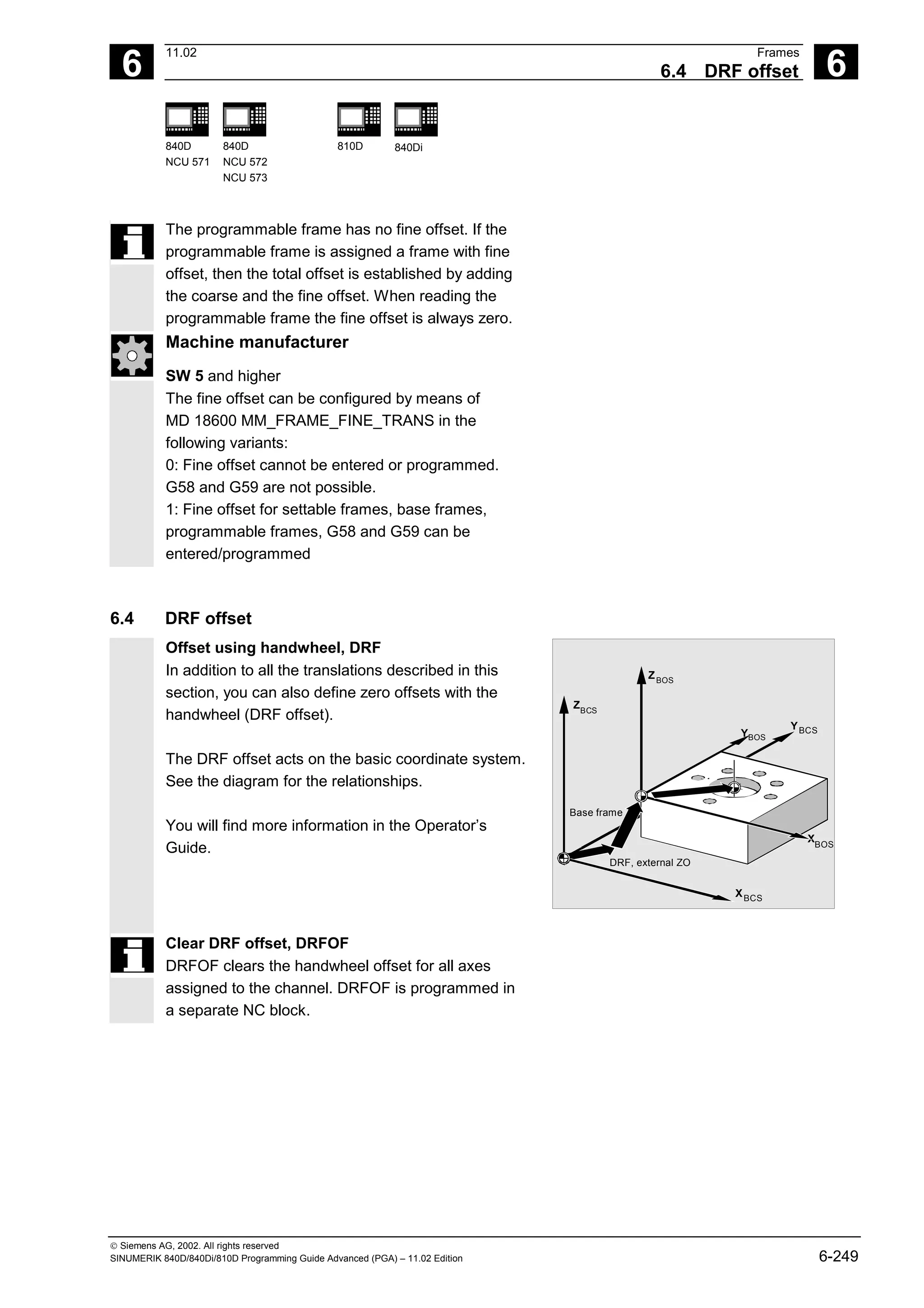
![6
Frames 11.02
6.5 External zero offset 6
840D
NCU 571
840D
NCU 572
NCU 573
810D 840Di
Siemens AG, 2002. All rights reserved
6-250 SINUMERIK 840D/840Di/810D Programming Guide Advanced (PGA) – 11.02 Edition
6.5 External zero offset
External zero offset
This is another way of moving the zero point
between the basic and workpiece coordinate
system.
Only linear translations can be programmed with the
external zero offset.
Programming offset values, $AA_ETRANS
The offset values are programmed by assigning the
axis-specific system variables.
Assigning offset value
$AA_ETRANS[axis]=RI
RI
is the arithmetic variable of type REAL which
contains the new value.
The external offset is generally set by the PLC and
not specified in the parts program.
YMCS
YMCS
XMCS
YBCS
XBCS
YBOS
XBOS
YSZS
XSZS
Preset offset
Kinematic transformation
DRF offset
External zero offset
G54...G599
Basic frame
The value entered in the parts program only
becomes active when the corresponding signal is
enabled at the VDI interface (NCU-PLC interface).](https://image.slidesharecdn.com/fadaladvancedprogrammingmanual-220505063253/75/Fadal-Advanced-Programming-Manual-pdf-250-2048.jpg)
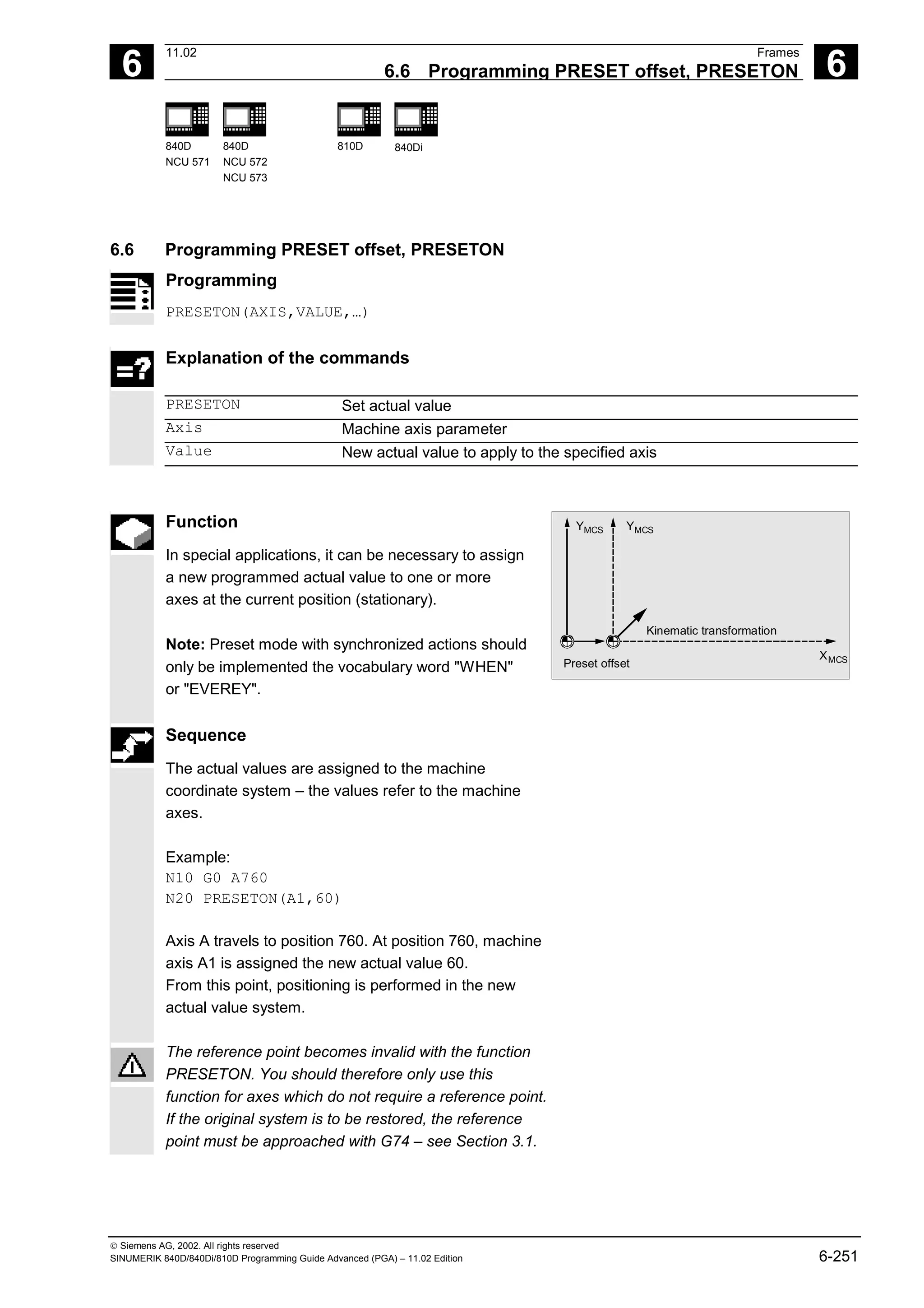
![6
Frames 11.02
6.8 Frame calculation from 3 measuring points in the area: MEAFRAME 6
840D
NCU 571
840D
NCU 572
NCU 573
810D 840Di
Siemens AG, 2002. All rights reserved
6-254 SINUMERIK 840D/840Di/810D Programming Guide Advanced (PGA) – 11.02 Edition
Programming
MEAFRAME(IDEAL_POINT,MEAS_POINT,FIT_QUALITY)
Explanation of the commands
MEAFRAME Frame calculation of three measured points in space
IDEAL_POINT 2-dim. array of real data containing the three coordinates of the ideal
points
MEAS_POINT 2-dim. array of real data containing the three coordinates of the measured
points
FIT_QUALITY Variable of type real returning the following information:
-1: The ideal points are located approximately on a straight line: The
frame could not be calculated. The frame variable returned
contains a neutral frame.
-2: The measured points are located approximately on a straight line:
The frame could not be calculated. The frame variable returned
contains a neutral frame.
-4: The calculation of the rotation matrix failed for a different reason
Positive value:
Sum of the distortions (distances between the points) needed to
reshape the measured triangle into one that is congruent to the
ideal triangle.
Application example
; Parts program 1
;
DEF FRAME CORR_FRAME
;
; Setting measured points
DEF REAL IDEAL_POINT[3,3] = SET(10.0,0.0,0.0, 0.0,10.0,0.0, 0.0,0.0,10.0)
DEF REAL MEAS_POINT[3,3] = SET(10.1,0.2,-0.2, -0.2,10.2,0.1, -0.2,0.2, 9.8); for test
DEF REAL FIT_QUALITY = 0
;
DEF REAL ROT_FRAME_LIMIT = 5; allows max. 5
o
rotation of the part position
DEF REAL FIT_QUALITY_LIMIT = 3; allows max. 3 mm distortion between the ideal;
and the measured triangle
DEF REAL SHOW_MCS_POS1[3]
DEF REAL SHOW_MCS_POS2[3]
DEF REAL SHOW_MCS_POS3[3]
; =======================================================
;](https://image.slidesharecdn.com/fadaladvancedprogrammingmanual-220505063253/75/Fadal-Advanced-Programming-Manual-pdf-254-2048.jpg)
![6
11.02 Frames
6.8 Frame calculation from 3 measuring points in the area: MEAFRAME 6
840D
NCU 571
840D
NCU 572
NCU 573
810D 840Di
Siemens AG, 2002. All rights reserved
SINUMERIK 840D/840Di/810D Programming Guide Advanced (PGA) – 11.02 Edition 6-255
N100 G01 G90 F5000
N110 X0 Y0 Z0
;
N200 CORR_FRAME=MEAFRAME(IDEAL_POINT,MEAS_POINT,FIT_QUALITY)
;
N230 IF FIT_QUALITY < 0
SETAL(65000)
GOTOF NO_FRAME
ENDIF
,
N240 IF FIT_QUALITY > FIT_QUALITY_LIMIT
SETAL(65010)
GOTOF NO_FRAME
ENDIF
;
N250 IF CORR_FRAME[X,RT] > ROT_FRAME_LIMIT; limiting the 1st RPY angle
SETAL(65020)
GOTOF NO_FRAME
ENDIF
;
N260 IF CORR_FRAME[Y,RT] > ROT_FRAME_LIMIT; limiting the 2nd RPY angle
SETAL(65021)
GOTOF NO_FRAME
ENDIF
;
N270 IF CORR_FRAME[Z,RT] > ROT_FRAME_LIMIT; limiting the 3rd RPY angle
SETAL(65022)
GOTOF NO_FRAME
ENDIF
;
N300 $P_IFRAME=CORR_FRAME; activate the probe frame via a settable frame
;
; check the frame by positioning the geometry axes at the ideal points
;
N400 X=IDEAL_POINT[0,0] Y=IDEAL_POINT[0,1] Z=IDEAL_POINT[0,2]
N410 SHOW_MCS_POS1[0]=$AA_IM[X]
N420 SHOW_MCS_POS1[1]=$AA_IM[Y]
N430 SHOW_MCS_POS1[2]=$AA_IM[Z]
;
N500 X=IDEAL_POINT[1,0] Y=IDEAL_POINT[1,1] Z=IDEAL_POINT[1,2]
N510 SHOW_MCS_POS2[0]=$AA_IM[X]
N520 SHOW_MCS_POS2[1]=$AA_IM[Y]
N530 SHOW_MCS_POS2[2]=$AA_IM[Z]
;
N600 X=IDEAL_POINT[2,0] Y=IDEAL_POINT[2,1] Z=IDEAL_POINT[2,2]
N610 SHOW_MCS_POS3[0]=$AA_IM[X]
N620 SHOW_MCS_POS3[1]=$AA_IM[Y]
N630 SHOW_MCS_POS3[2]=$AA_IM[Z]
;](https://image.slidesharecdn.com/fadaladvancedprogrammingmanual-220505063253/75/Fadal-Advanced-Programming-Manual-pdf-255-2048.jpg)
![6
Frames 11.02
6.9 NCU-global frames (SW 5 and higher) 6
840D
NCU 571
840D
NCU 572
NCU 573
810D 840Di
Siemens AG, 2002. All rights reserved
6-256 SINUMERIK 840D/840Di/810D Programming Guide Advanced (PGA) – 11.02 Edition
N700 G500; Deactivate settable frame, as preset with zero frame (no value set)
;
NO_FRAME:
M0
M30
6.9 NCU-global frames (SW 5 and higher)
Function
NCU-global frames are only available once for all
channels of each NCU. NCU-global frames can be
written and read from all channels. The NCU-global
frames are activated in the respective channel.
Channel axes and machine axes with offsets can be
scaled and mirrored by means of global frames.
With global frames there is no geometrical
relationship between the axes. Therefore, it is not
possible to perform rotations or program geometry
axis identifiers.
• It is not possible to use global frames for rotations.
Programming a rotation is refused and alarm:
"18310 channel %1 block %2 frame: rotation not
allowed" is displayed.
• Chaining of global frames and channel-specific
frames is possible. The resulting frame contains all
frame elements including rotations for all axes. If a
frame with rotation elements is assigned to a global
frame, it is rejected and alarm "Frame: rotation not
allowed" is displayed.
NCU-global base frames: $P_NCBFR[n]
You can configure up to 8 NCU-global basic frames.](https://image.slidesharecdn.com/fadaladvancedprogrammingmanual-220505063253/75/Fadal-Advanced-Programming-Manual-pdf-256-2048.jpg)
![6
11.02 Frames
6.9 NCU-global frames (SW 5 and higher) 6
840D
NCU 571
840D
NCU 572
NCU 573
810D 840Di
Siemens AG, 2002. All rights reserved
SINUMERIK 840D/840Di/810D Programming Guide Advanced (PGA) – 11.02 Edition 6-257
Machine manufacturer
The number of global base frames is configured via
machine data. (See /FB/ K2, Axes, Coordinate
Systems, Frames)
Channel-specific base frames can be present at the
same time.
Global frames can be written and read from all
channels of an NCU. When writing global frames, the
user must pay attention to channel coordination, for
example, by using Wait marks (WAITMC).
NCU-global settable frames: $P_UIFR[n]
All settable frames G500, G54...G599 can be
configured either NCU-global or channel-specific.
Machine manufacturer
All settable frames can be reconfigured as global frames
via MD 18601 MM_NUM_GLOBAL_USER_FRAMES.
See /FB/ K2, Axes, Coordinate Systems, Frames.
Channel axis identifiers and machine axis identifiers
can be used as axis identifiers for the frame program
commands. Programming of geometry identifiers is
rejected with an alarm.
6.9.1 Channel-specific frames
Function
The number of base frames can be configured in the
channel via MD 28081 MM_NUM_BASE_FRAMES.
The standard configuration provides at least one base
frame per channel. A maximum of eight base frames
are supported per channel. In addition to the eight
base frames, there can also be eight NCU-global base
frames in the channel.](https://image.slidesharecdn.com/fadaladvancedprogrammingmanual-220505063253/75/Fadal-Advanced-Programming-Manual-pdf-257-2048.jpg)
![6
Frames 11.02
6.9 NCU-global frames (SW 5 and higher) 6
840D
NCU 571
840D
NCU 572
NCU 573
810D 840Di
Siemens AG, 2002. All rights reserved
6-258 SINUMERIK 840D/840Di/810D Programming Guide Advanced (PGA) – 11.02 Edition
Settable frames/base frames can be written and read
from the control and the PLC
• via the parts program and
• via the OPI.
Fine offset is also possible for global frames.
Suppression of global frames also takes place, as is
the case with channel-specific frames, via G53, G153,
SUPA and G500.
$P_CHBFR[n]
The base frames can be read and written via system
variable $P_CHBFR[n]. When writing a base frame,
the chained total base frame is not activated; it is
only activated when the G500, G54..G599 instruction
is executed. The variable mainly serves as memory
for writing processes to the MMC and PLC base
frame. These frame variables are saved by data
backup.
First basic frame in the channel
Writing to a predefined variable $P_UBFR will not
activate the basic frame with array index 0
simultaneously, but it will be activated only after a
G500, G54..G599 command is executed. The
variable can also be written and read in the program.
$P_UBFR
$P_UBFR is identical to $P_CHBFR[0].
As standard, there is always a base frame in the
channel making the system variable compatible with
older versions. If there is no channel-specific base
frame, an alarm is issued at read/write: "Frame:
instruction not permissible".](https://image.slidesharecdn.com/fadaladvancedprogrammingmanual-220505063253/75/Fadal-Advanced-Programming-Manual-pdf-258-2048.jpg)
![6
11.02 Frames
6.9 NCU-global frames (SW 5 and higher) 6
840D
NCU 571
840D
NCU 572
NCU 573
810D 840Di
Siemens AG, 2002. All rights reserved
SINUMERIK 840D/840Di/810D Programming Guide Advanced (PGA) – 11.02 Edition 6-259
6.9.2 Frames active in the channel
Function
SW 6.1 and higher
Current system frames for
$P_PARTFRAME TCARR and PAROT
$P_SETFRAME preset actual value memory and
scratching,
$P_EXTFRAME zero offset external,
You can read and write the current system frame in
the parts program via these system variables.
$P_NCBFRAME[n]
Current NCU-global basic frames
You can read and write the current global basic
frame field elements via system variable
$P_NCBFRAME[n]. The resulting total base frame
is calculated by means of the write process in the
channel.
The modified frame is only active in the channel in
which the frame was programmed. If the frame is
to be changed for all channels of an NCU, both [n]
and $P_NCBFRAME[n] have to be programmed.
The other channels must then still activate the
frame with, for example, G54. When writing a base
frame, the total base frame is calculated again.
$P_CHBFRAME[n]
Current channel basic frames
You can read and write the current channel basic
frame field elements via system variable
$P_CHBFRAME[n]. The resulting total base frame
is calculated by means of the write process in the
channel. When writing a base frame, the total base
frame is calculated again.](https://image.slidesharecdn.com/fadaladvancedprogrammingmanual-220505063253/75/Fadal-Advanced-Programming-Manual-pdf-259-2048.jpg)
![6
Frames 11.02
6.9 NCU-global frames (SW 5 and higher) 6
840D
NCU 571
840D
NCU 572
NCU 573
810D 840Di
Siemens AG, 2002. All rights reserved
6-260 SINUMERIK 840D/840Di/810D Programming Guide Advanced (PGA) – 11.02 Edition
$P_BFRAME
Current first basic frame in the channel
You can read and write the current basic frame with
array index 0, which applies for the channel, in the
parts program via the predefined frame variable
$P_BFRAME. The written basic frame is
immediately included in the calculation.
$P_BFRAME is identical to $P_CHBFRAME[0]. The
default is for the system variable to always have a
valid value. If there is no channel-specific base
frame, an alarm is issued at read/write: "Frame:
instruction not permissible".
$P_ACTBFRAME
Total basic frame
Variable $P_ACTBFRAME determines the chained
total basic frame. The variable can only be read.
$P_ACTBFRAME corresponds to
$P_NCBFRAME[0] : ... : $P_NCBFRAME[n] :
$P_CHBFRAME[0] : ... : $P_CHBFRAME[n].
Y
BCS
Y
BCS
X
X
BCS
BCS = Basic coordinate system
BOS = Basic origin system
BOS
Y BOS
X BOS
$P_NCBFRAME[0]
$P_NCBFRAME[n], n programmable via $MN_MM_NUM_GLOBAL_BASE_FRAMES
$P_CHBFRAME[0] = $P_BFRAME
$P_CHBFRAME[n], n programmable via $MC_MM_NUM_BASE_FRAMES
$P_ACTBFRAME
$P-ACTBFRAME = $P_NCBFRAME[0] : $P_NCBFRAME[n] : $P_CHBFRAME[0] : $P_CHBFRAME[n]
$P_CHBFRMASK and $P_NCBFRMASK
Total basic frame
Via system variables $P_CHBFRMASK and
$P_NCBFRMASK, the user can select the basic frames
to be included in the calculation of the "total" basic frame.
The variables can only be programmed in the program
and read via OPI. The value of the variable is interpreted
as bit mask and determines which base frame field
element of $P_ACTBFAME is included in the calculation.](https://image.slidesharecdn.com/fadaladvancedprogrammingmanual-220505063253/75/Fadal-Advanced-Programming-Manual-pdf-260-2048.jpg)
![6
11.02 Frames
6.9 NCU-global frames (SW 5 and higher) 6
840D
NCU 571
840D
NCU 572
NCU 573
810D 840Di
Siemens AG, 2002. All rights reserved
SINUMERIK 840D/840Di/810D Programming Guide Advanced (PGA) – 11.02 Edition 6-261
You can specify with $P_CHBFRMASK which channel-
specific base frames, and with $P_NCBFRMASK which
NCU-global base frames, are to be included in the
calculation.
By programming the variables the total base frame and
the total frame are calculated again. After a Reset is
performed, the basic setting value is
$P_CHBFRMASK = $MC_CHBFRAME_RESET_MASK and
$P_NCBFRMASK = $MN_NCBFRAME_RESET_MASK.
e.g.
$P_NCBFRMASK = 'H81' ; $P_NCBFRAME[0] : $P_NCBFRAME[7]
$P_CHBFRMASK = 'H11' ; $P_CHBFRAME[0] : $P_CHBFRAME[4]
$P_IFRAME
Current settable frame
You can read and write the current settable frame,
which applies in the channel, in the parts program
via the predefined frame variable $P_IFRAME. The
written settable frame is immediately included in the
calculation.
With NCU-global settable frames, the modified frame is
only active in the channel in which the frame was
programmed. If the frame is to be changed for all
channels of an NCU, both $P_UIFR[n] and $P_IFRAME
have to be programmed. The other channels must then
still activate the respective frame with, for example,
G54.
SW 6.1 and higher
Current system frames for
$P_TOOLFRAME TOROT and TOFRAME
SW 6.3 and higher
$P_WPFRAME Workpiece reference points
You can read and write the current system frame in
the parts program via these system variables.](https://image.slidesharecdn.com/fadaladvancedprogrammingmanual-220505063253/75/Fadal-Advanced-Programming-Manual-pdf-261-2048.jpg)
![6
11.02 Frames
6.9 NCU-global frames (SW 5 and higher) 6
840D
NCU 571
840D
NCU 572
NCU 573
810D 840Di
Siemens AG, 2002. All rights reserved
SINUMERIK 840D/840Di/810D Programming Guide Advanced (PGA) – 11.02 Edition 6-263
$P_ACTFRAME
$P_UIFR[n]
=
Activated via
G500, G54...G599
Input
via MMC
Input via program, e.g.
$P_CHBFR=CTRANS(Z,10)
Input
via MMC
Input via program, e.g.
$P_UIFR[n]=CTRANS(X,10)
Input via program, e.g.
$P_NCBFRAME[1]=CTRANS(X,10)
Input via program, e.g.
$P_IFRAME=CTRANS(X,10)
Input via program, e.g.
$P_PFRAME=CTRANS(X,10)
bzw. TRANS X10
$P_CHBFR[n] $P_NCBFR[n]
:
$P_NCBFR=CTRANS(X,10)
NCU-global
Channel-specific
$P_ACTRAME :
$P_EXTFRAME :
:
$P_TOOLFRAME : :
:
Activated via
G500, G54...G599
Channel-specific
system frames
Data management frames
Active total frame
$P_PFRAME :
: $P_CYCFRAME
$P_WPFRAME :
$P_EXTFR
$P_SETFR
$P_WPFR
$P_CYCTFR
$P_PARTFR
$P_TOOLFR
NCU basic frames frames
$P_IFRAME :
$P_PARTFRAM : $P_SETFRAME :
Frame chaining
The current frame consists of the total basic frame,
the settable frame, the system frame and the
programmable frame according to the current total
frame mentioned above.
Kinematic transformation
Handwheel (DRF) offset, override motion,
[external zero offset]
MCS
WCS
SZS
BZS
BCS
Frame for cycles,
programmable frame
System frame for TOROT
(TOFRAME), workpieces
G54 ... G599 settable frame,
channel-specific or NCU-global
Chained filed of basic frames,
channel-specific of NCU-global
Chained system frames for actual value setting,
scratching, external zero offset, PAROT
MCS = Machine Coordniate System BCS = Basic Coordinate System WCS = Workpiece Coordinate System
BZS = Basic Zero System SZS = Settable Zero System
Frame chain
Reference point offset
n](https://image.slidesharecdn.com/fadaladvancedprogrammingmanual-220505063253/75/Fadal-Advanced-Programming-Manual-pdf-263-2048.jpg)
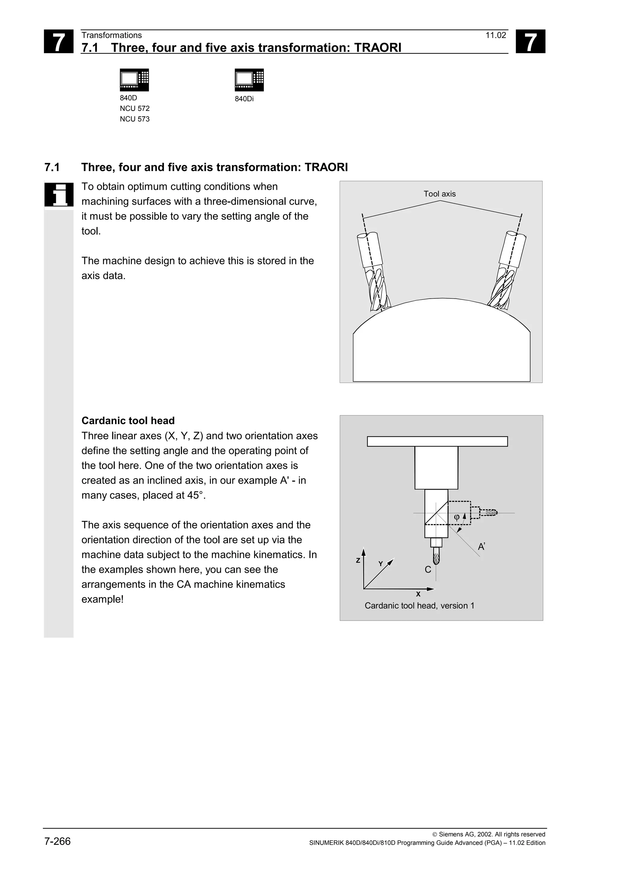
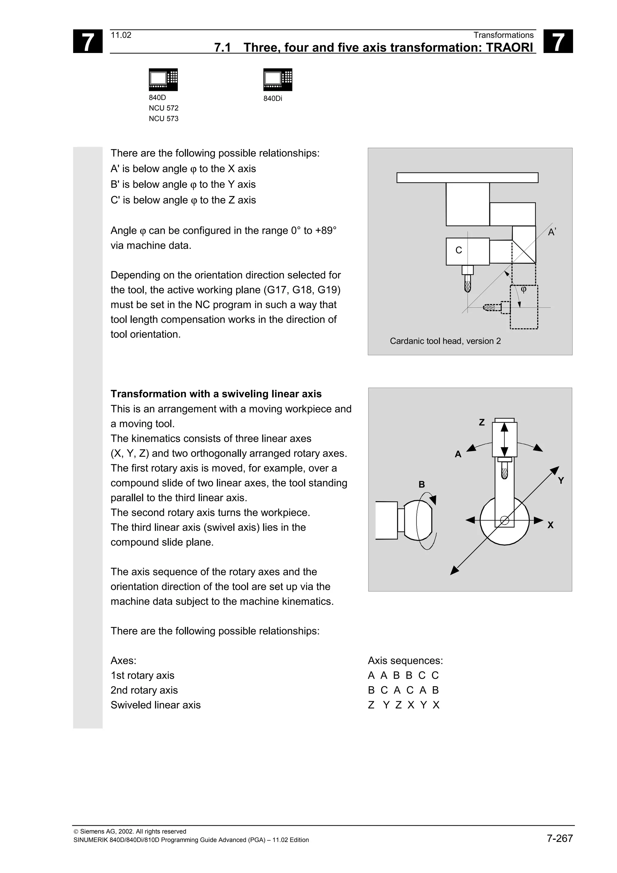
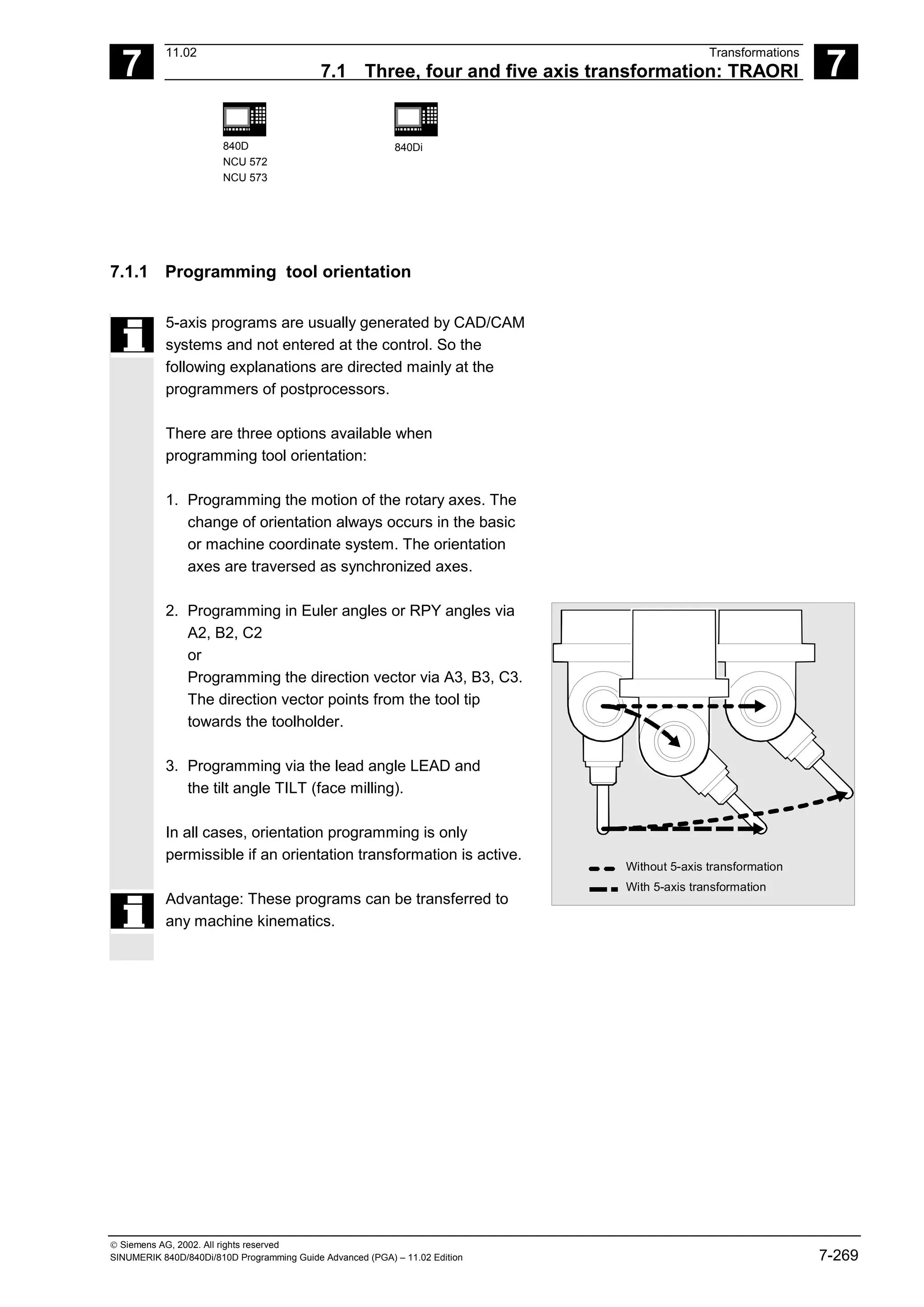
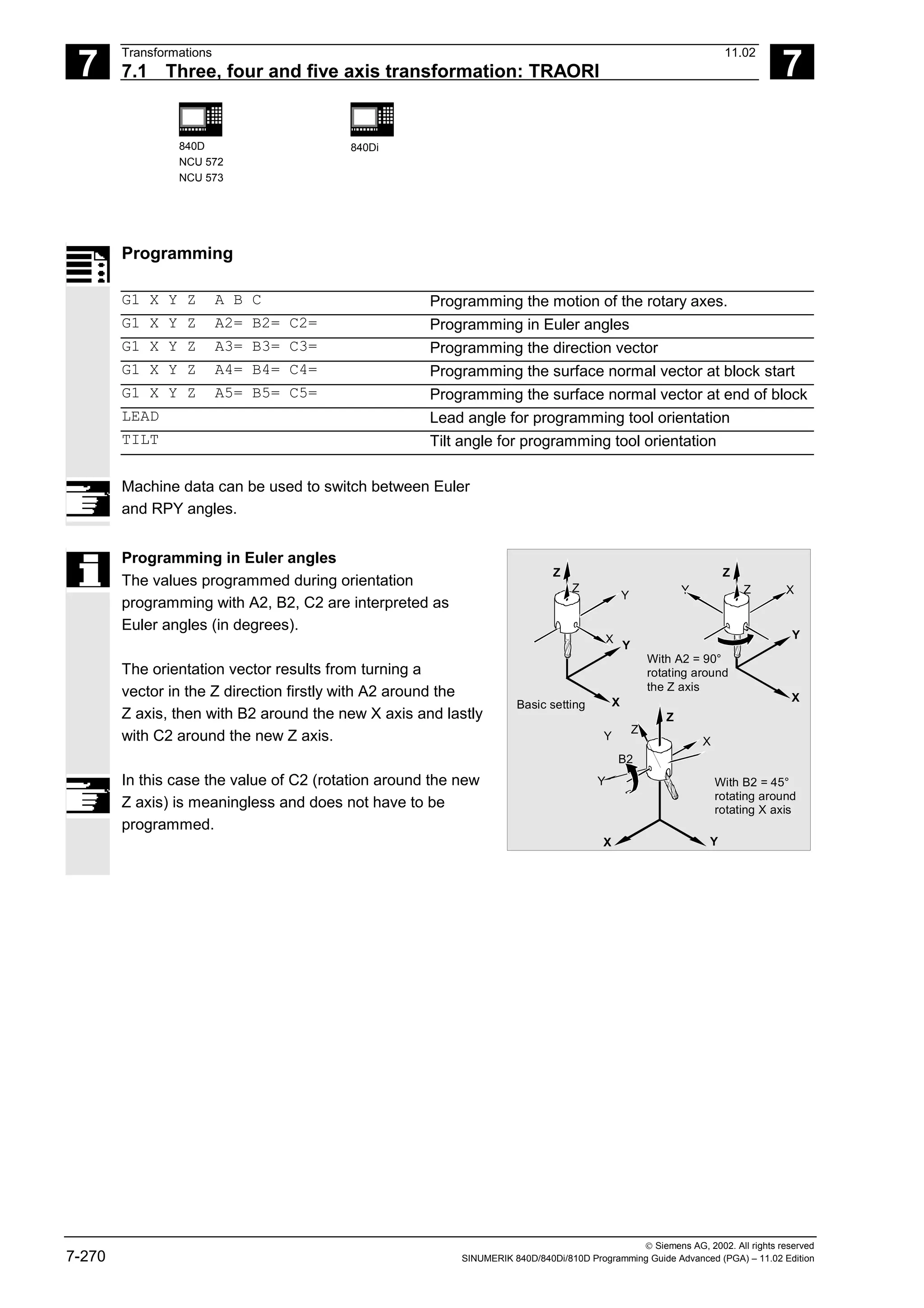
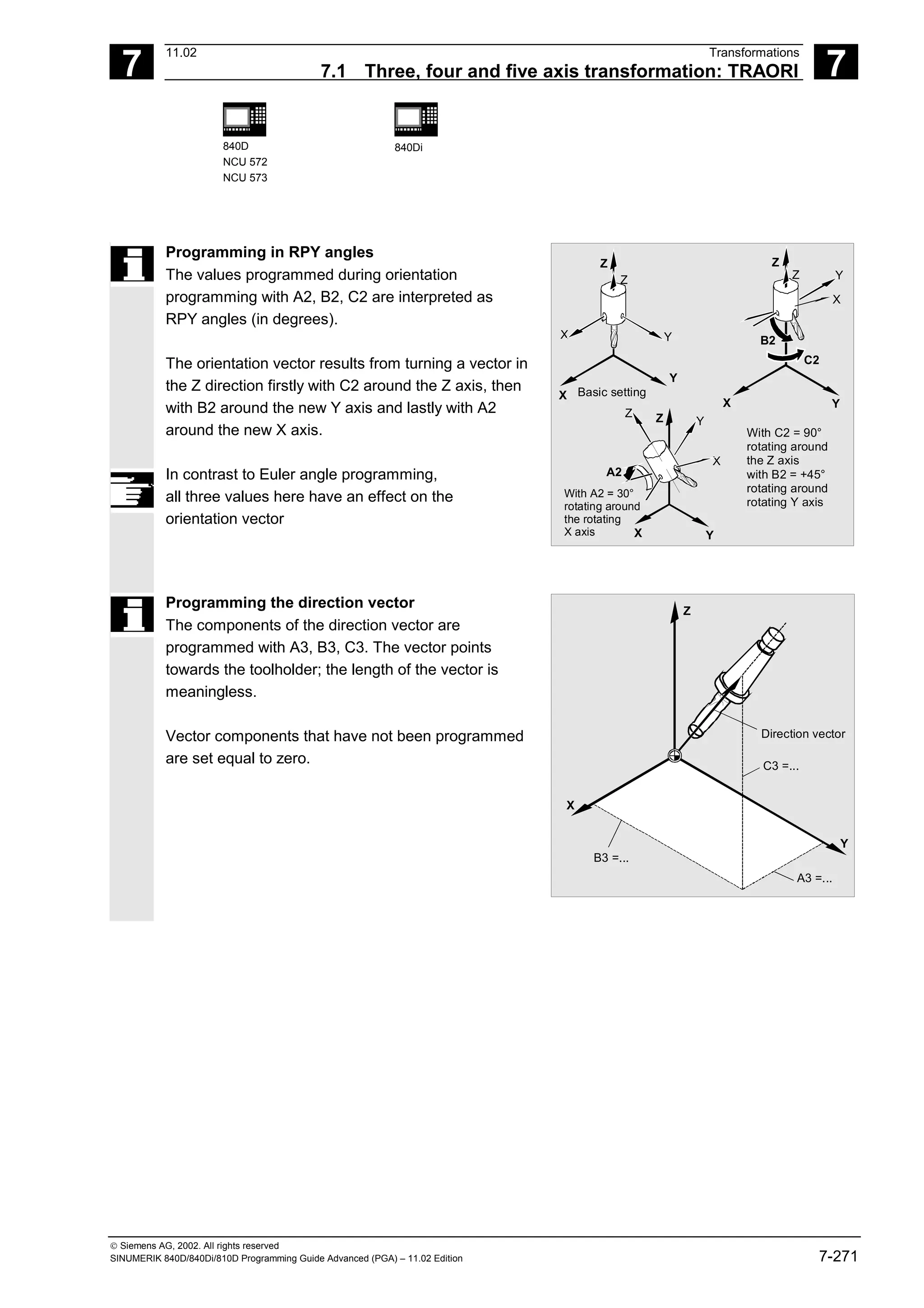
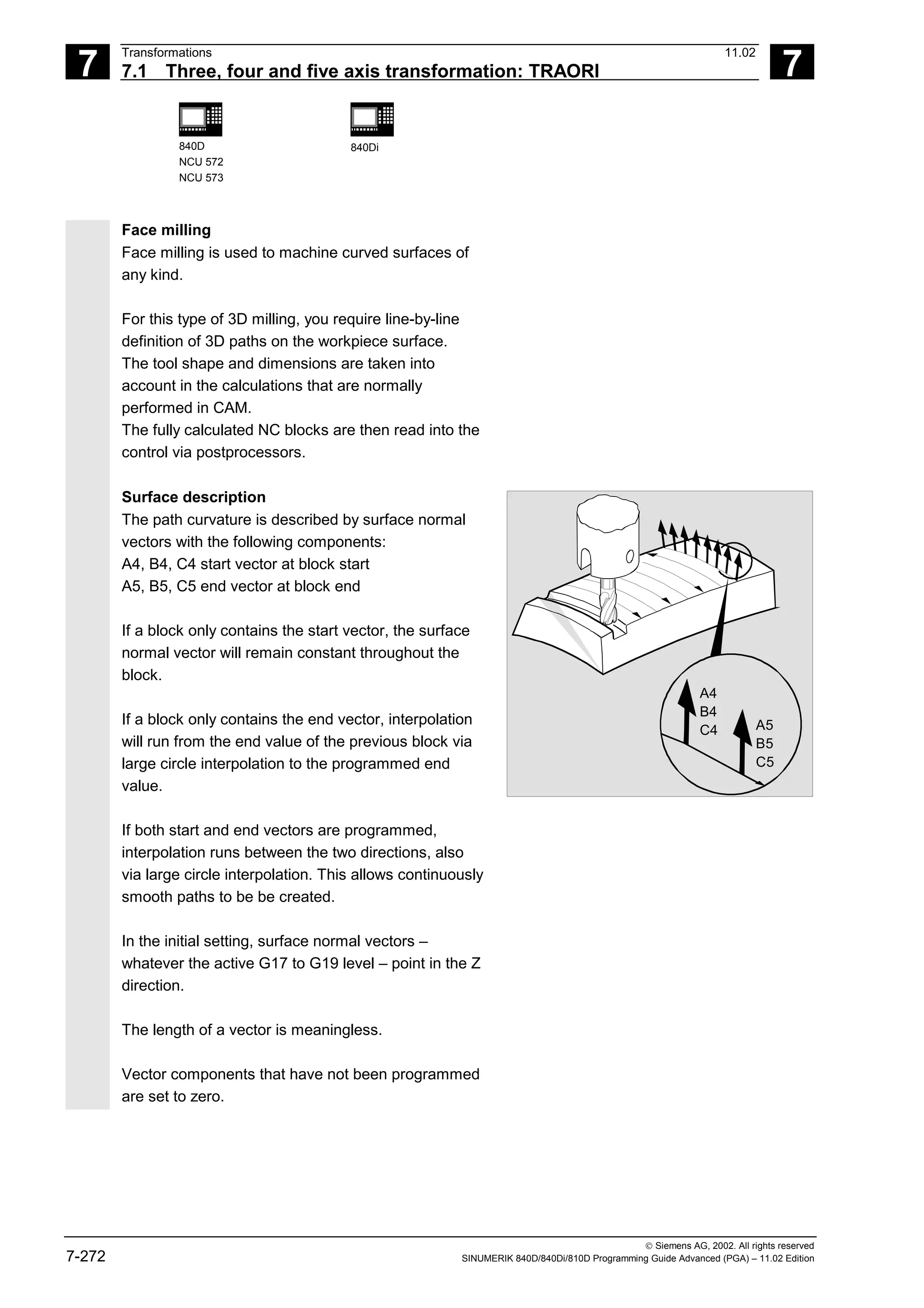
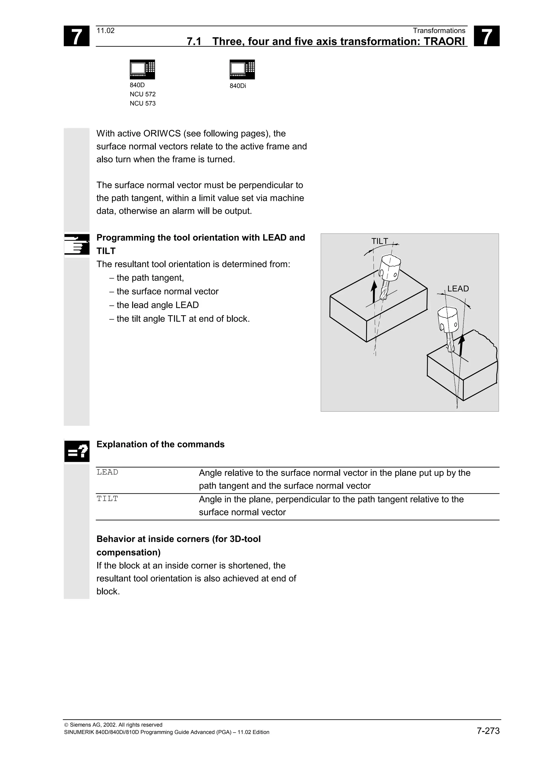
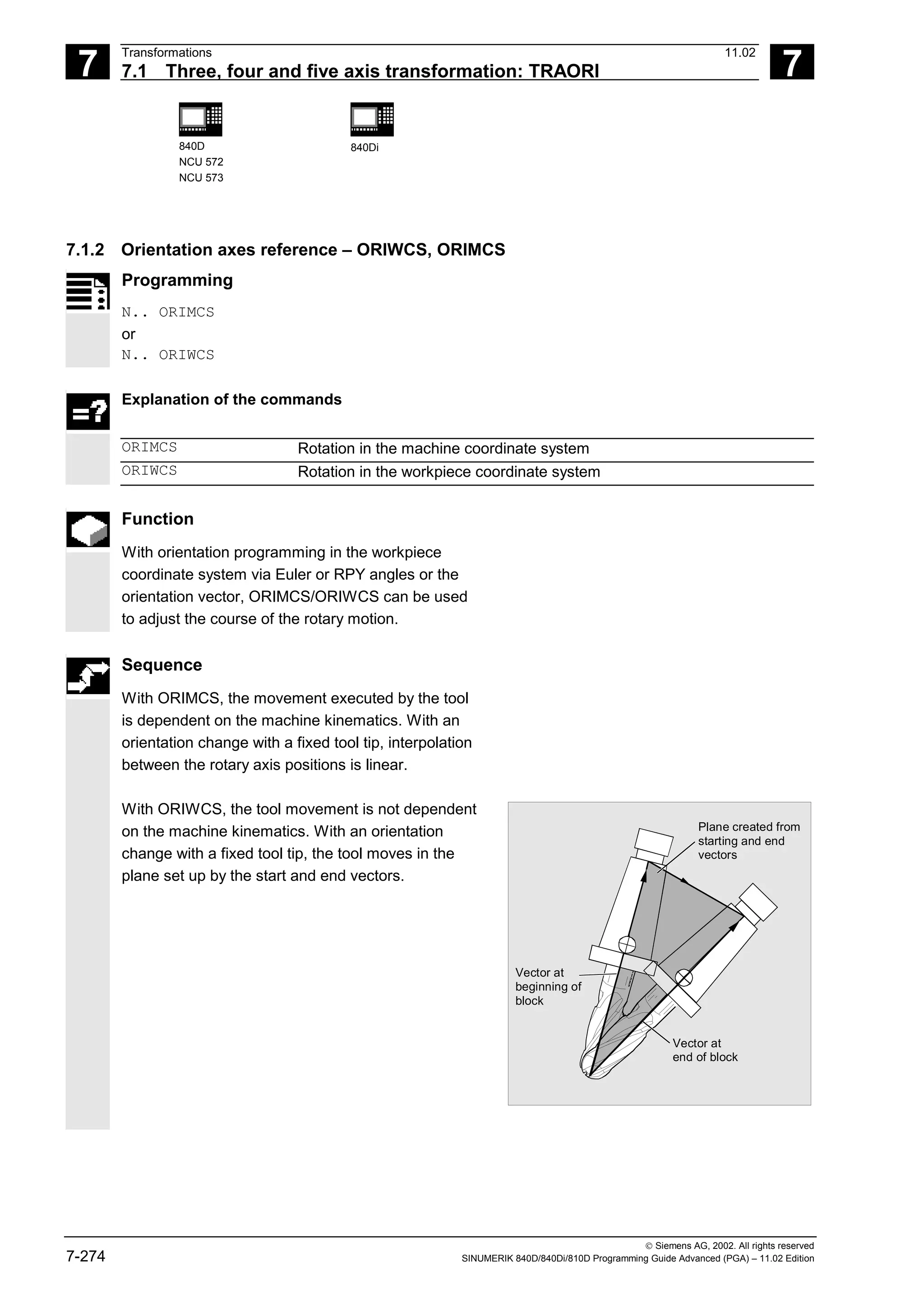
![7
Transformations 11.02
7.1 Three, four and five axis transformation: TRAORI 7
840D
NCU 572
NCU 573
840Di
Siemens AG, 2002. All rights reserved
7-278 SINUMERIK 840D/840Di/810D Programming Guide Advanced (PGA) – 11.02 Edition
Feed programming
FORI1 Feed for swiveling the orientation vector on the large circle
FORI2 Feed for the overlaid rotation around the swiveled orientation vector
With orientation movements, the programmable feed
corresponds to an angular velocity [degrees/min].
Effectiveness of the feed via G code:
When programming ORIAXES, the feed for an
orientation axis can be limited via the FL[ ]
instruction (feed limit).
When programming ORIVECT, the feed must be
programmed with FORI1 or FORI2. FORI1 and
FORI2 must only be programmed once in the NC
block. Traversal always takes the shortest path
during this programming.
The smallest feed always operates for the overlaid
motion of turning and swiveling. With orientation
movements, the feed corresponds to an angular
velocity [degrees/min].
If geometry axes and orientation axes traverse a
common path, the traversing movement is
determined from the smallest feed.](https://image.slidesharecdn.com/fadaladvancedprogrammingmanual-220505063253/75/Fadal-Advanced-Programming-Manual-pdf-278-2048.jpg)
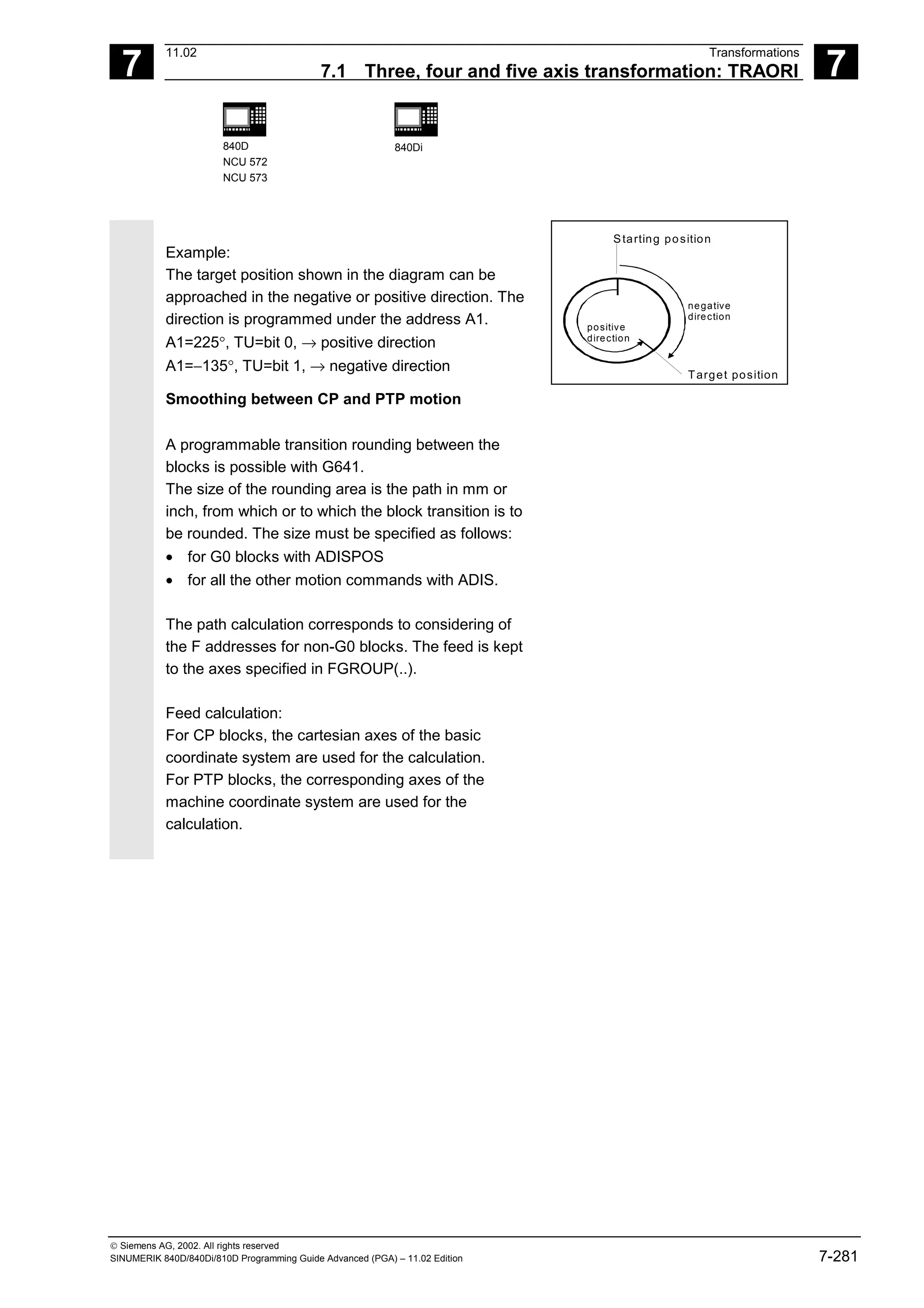
![7
Transformations 11.02
7.1 Three, four and five axis transformation: TRAORI 7
840D
NCU 572
NCU 573
840Di
Siemens AG, 2002. All rights reserved
7-282 SINUMERIK 840D/840Di/810D Programming Guide Advanced (PGA) – 11.02 Edition
Additional notes
Mode change
The "Cartesian PTP travel" function is only useful in
the AUTO and MDA modes of operation. When
changing the mode to JOG, the current setting is
retained.
When the G code PTP is set, the axes will traverse
in MCS. When the G code CP is set, the axes will
traverse in WCS.
Power On / Reset
After a power ON or after a Reset, the setting is
dependent on the machine data
$MC_GCODE_RESET_VALUES[48]. The default traversal
mode setting is "CP".
Repositioning
If the function "Cartesian PTP travel" was set during
the interruption block, PTP can also be used for
repositioning.
Overlaid movements
DRF offset or external zero offset are only possible
to a limited extent in cartesian PTP travel. When
changing from PTP to CP motion, there must be no
overrides in the BCS.](https://image.slidesharecdn.com/fadaladvancedprogrammingmanual-220505063253/75/Fadal-Advanced-Programming-Manual-pdf-282-2048.jpg)
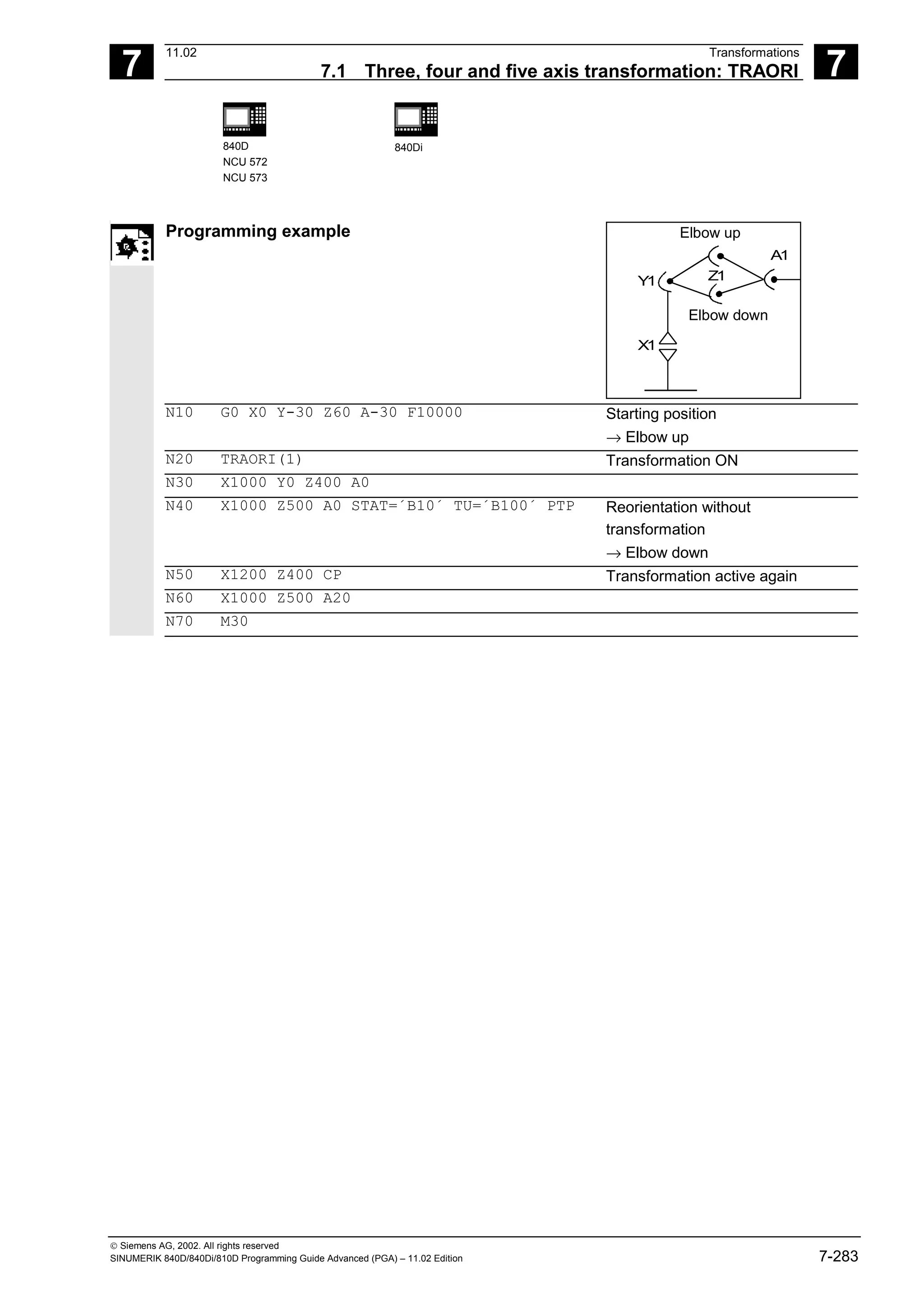
![7
Transformations 11.02
7.1 Three, four and five axis transformation: TRAORI 7
840D
NCU 572
NCU 573
840Di
Siemens AG, 2002. All rights reserved
7-284 SINUMERIK 840D/840Di/810D Programming Guide Advanced (PGA) – 11.02 Edition
7.1.6 Online tool length compensation (SW 6.4 and higher)
Programming
N.. TRAORI
N.. TOFFON(X,25)
N.. WHEN TRUE DO $AA_TOFF[X]
Explanation of the commands
TOFFON Tool Offset ON (activate online tool length compensation)
When activating, an offset value can be specified for the relevant direction of
compensation and this is immediately recovered.
TOFFOF Tool Offset OF (reset online tool length compensation)
The relevant compensation values are reset and a preprocessing stop is initiated.
X, Y, Z, Direction of compensation for the specified offset value
Function
Use the system variable $AA_TOFF[ ] to overlay the
effective tool lengths in accordance with the three
tool directions three-dimensionally in real time.
The three geometry axis identifiers are used as the
index. This defines the number of active directions of
compensation by the geometry axes active at the
same time.
All the overrides can be active simultaneously.
Application
The online tool length compensation function can be
used for:
• orientation transformation TRAORI
• orientable toolholder TCARR
Note:
Online tool length compensation is an option, that
first has to be enabled. This function is only useful in
conjunction with an active orientation transformation
or an active orientable toolholder.](https://image.slidesharecdn.com/fadaladvancedprogrammingmanual-220505063253/75/Fadal-Advanced-Programming-Manual-pdf-284-2048.jpg)
![7
11.02 Transformations
7.1 Three, four and five axis transformation: TRAORI 7
840D
NCU 572
NCU 573
840Di
Siemens AG, 2002. All rights reserved
SINUMERIK 840D/840Di/810D Programming Guide Advanced (PGA) – 11.02 Edition 7-285
Additional notes
Block preparation
During block preparation in preprocessing, the
current tool length offset active in the main run is
also taken into consideration. To allow extensive use
to be made of the maximum permissible axis
velocity, it is necessary to stop block preparation
with a STOPRE preprocessing stop while a tool
offset is set up.
The tool offset is then always known at the time of
preprocessing if tool length compensations can no
longer be changed after program startup, or if,
following a change to the tool length compensations,
more blocks were executed than the IPO buffer
between preprocessing and main run can accept.
Variable $AA_TOFF_PREP_DIFF
The size of the difference between the current
compensation active in the interpolator and the
compensation active at the time the block was
prepared, can be queried in the
$AA_TOFF_PREP_DIFF[ ] variable.
Adjusting machine data and setting data
The following machine data is available for online
tool length compensation:
• MD 20610: ADD_MOVE_ACCEL_RESERVE
Reserve for velocity planning
• MD 21190: TOFF_MODE The content of the
system variable $AA_TOFF[ ] is recovered or
integrated as an absolute value.
• MD 21194: TOFF_VELO Velocity of the online
tool length compensation
• MD 21196: TOFF_ACCEL Acceleration of the
online tool length compensation
Setting data for presetting limit values
• SD 42970: TOFF_LIMIT Upper limit of the tool
length compensation value](https://image.slidesharecdn.com/fadaladvancedprogrammingmanual-220505063253/75/Fadal-Advanced-Programming-Manual-pdf-285-2048.jpg)
![7
Transformations 11.02
7.1 Three, four and five axis transformation: TRAORI 7
840D
NCU 572
NCU 573
840Di
Siemens AG, 2002. All rights reserved
7-286 SINUMERIK 840D/840Di/810D Programming Guide Advanced (PGA) – 11.02 Edition
Programming example
Tool length compensation selection
MD 21190: TOFF_MODE =1
MD 21194: TOFF_VELO[0] =1000
MD 21196: TOFF_VELO[1] =1000
MD 21194: TOFF_VELO[2] =1000
MD 21196: TOFF_ACCEL[0] =1
MD 21196: TOFF_ACCEL[1] =1
MD 21196: TOFF_ACCEL[2] =1
; Absolute values are approached
N5 DEF REAL XOFFSET
N10 TRAORI(1) ; Transformation ON
N20 TOFFON(Z) ; Activation of online tool length offset
; for the Z tool direction
N30 WHEN TRUE DO $AA_TOFF[Z] = 10
G4 F5
; For the Z tool direction, a tool length
; offset of 10 is interpolated
...
N40 TOFFON(X) ; Activation of online tool length offset
; for the X tool direction
N50 ID=1 DO $AA_TOFF[X] = $AA_IW[X2]
G4 F5
; For the X tool direction, an offset is
; executed subject to the position of axis
; X2
...
N100 XOFFSET = $AA_TOFF_VAL[X]
N120 TOFFON(X, -XOFFSET)
G4 F5
; Assign current offset in X direction
; For the X tool direction, the tool length
; offset will be returned to 0 again
Tool length compensation deselection
N10 TRAORI(1) ; Transformation ON
N20 TOFFON(X) ; Activating the Z tool direction
N30 WHEN TRUE DO $AA_TOFF[X] = 10
G4 F5
; For the X tool direction, a tool length
; offset of 10 is interpolated
...
N80 TOFFOF(X) ; Positional offset of the X tool direction
; is deleted: ...$AA_TOFF[X] = 0
; No axis is traversed
; To the current position in WCS, the
; positional offset is added in accordance
; with the current orientation
References
/FB/ F2, 3-axis to 5-axis transformations](https://image.slidesharecdn.com/fadaladvancedprogrammingmanual-220505063253/75/Fadal-Advanced-Programming-Manual-pdf-286-2048.jpg)
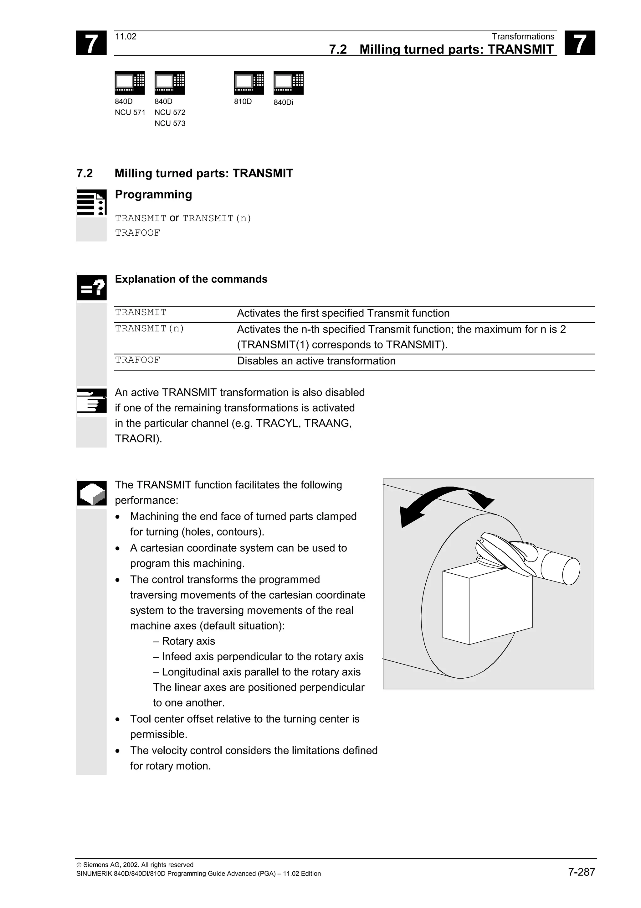
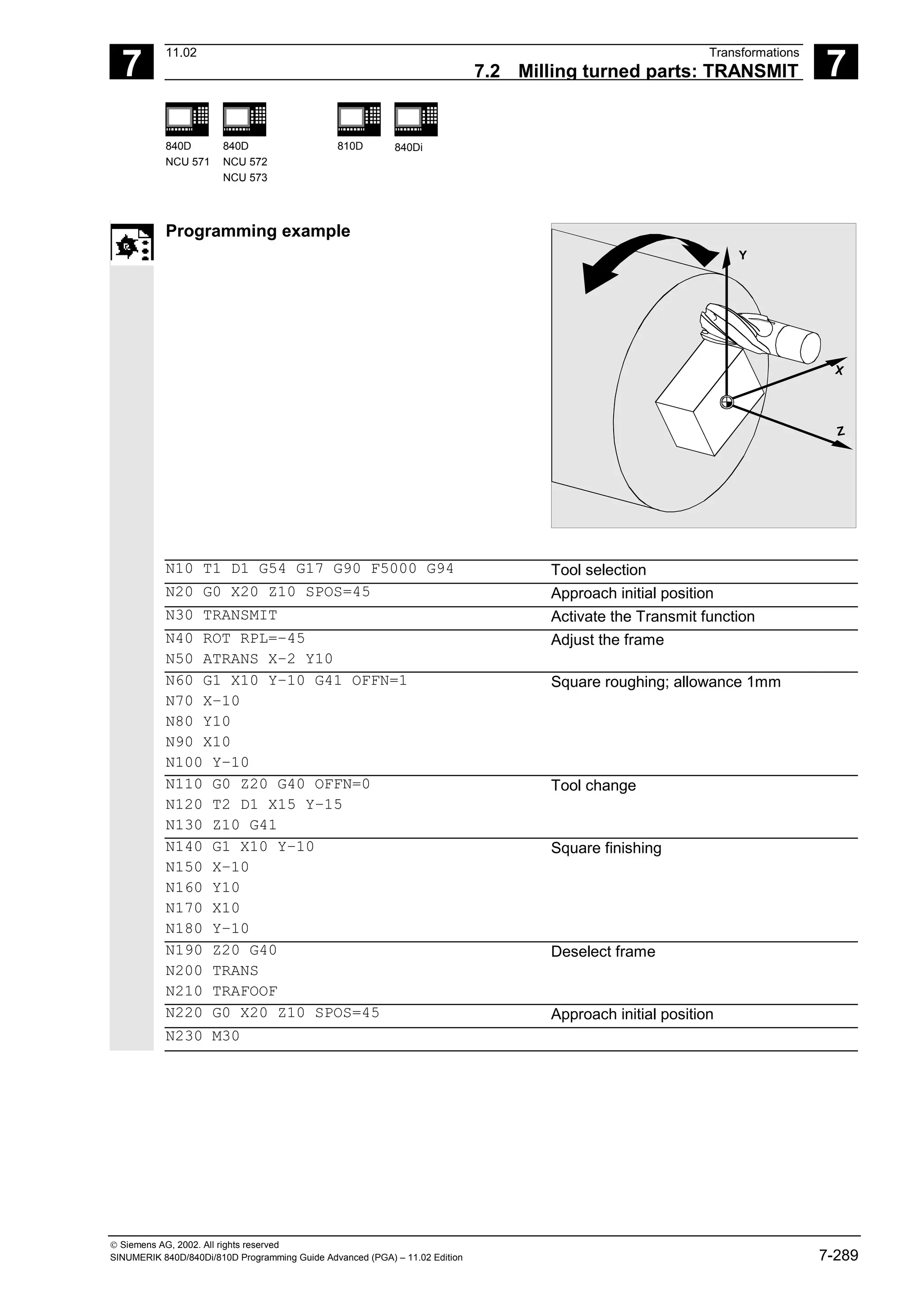
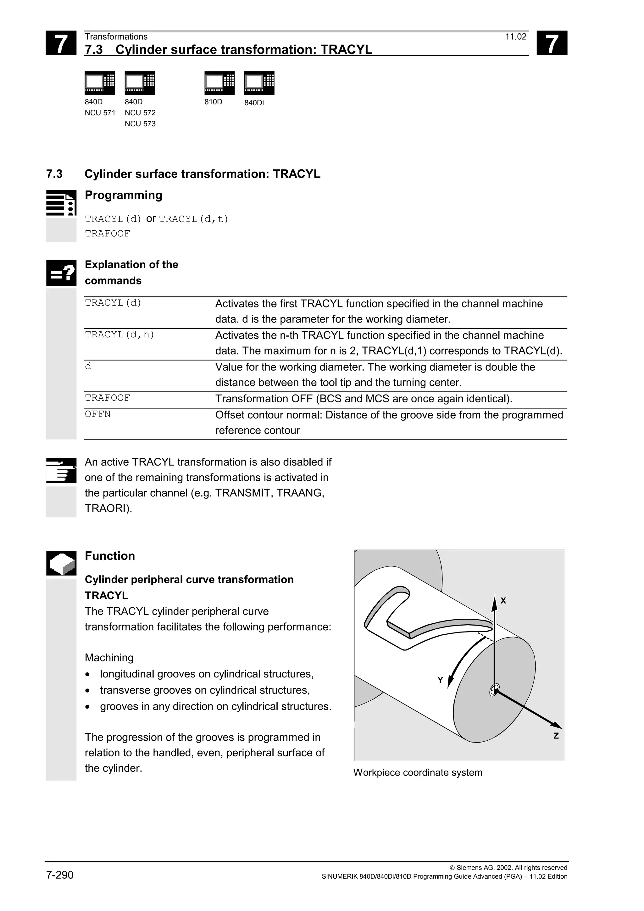
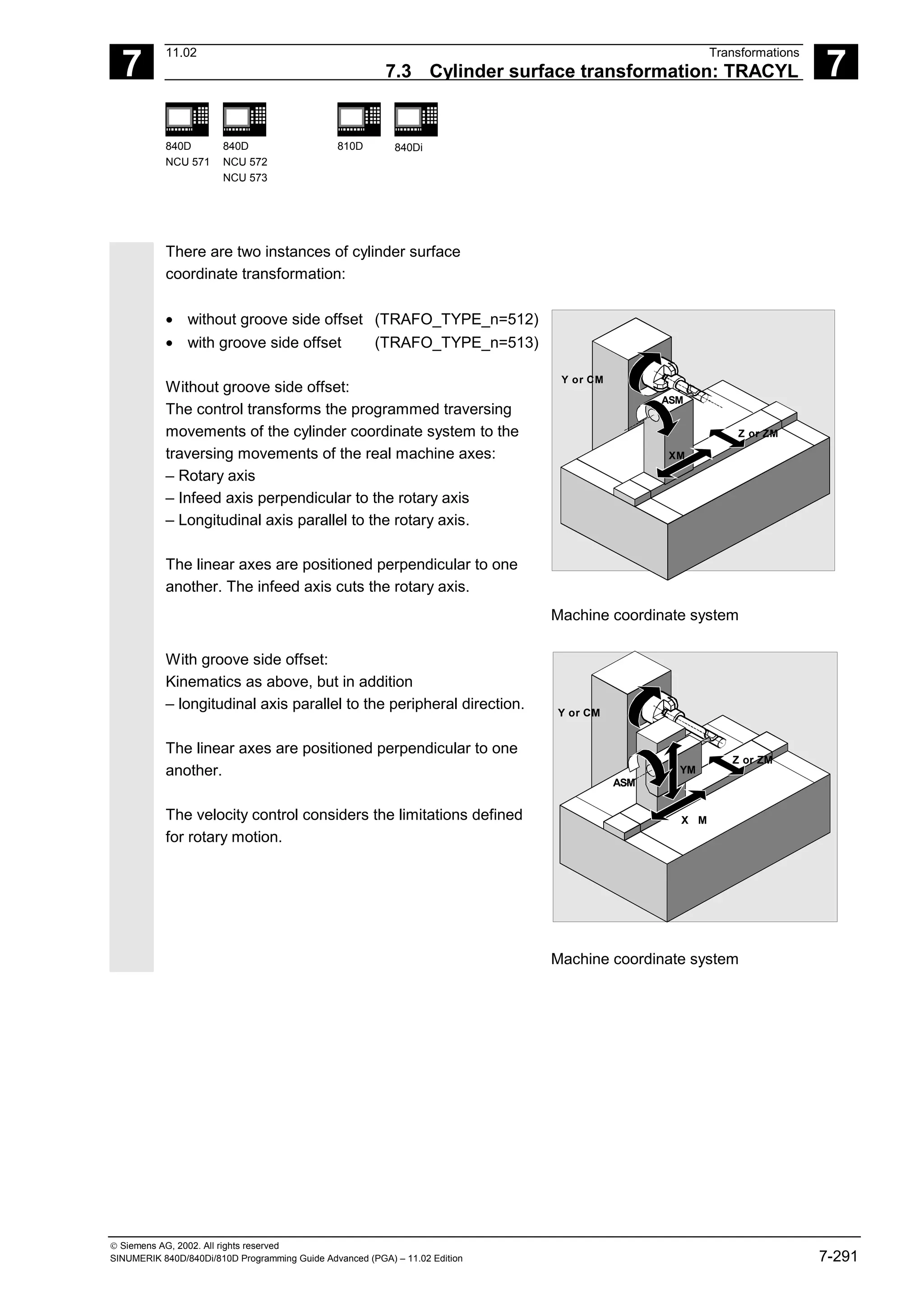
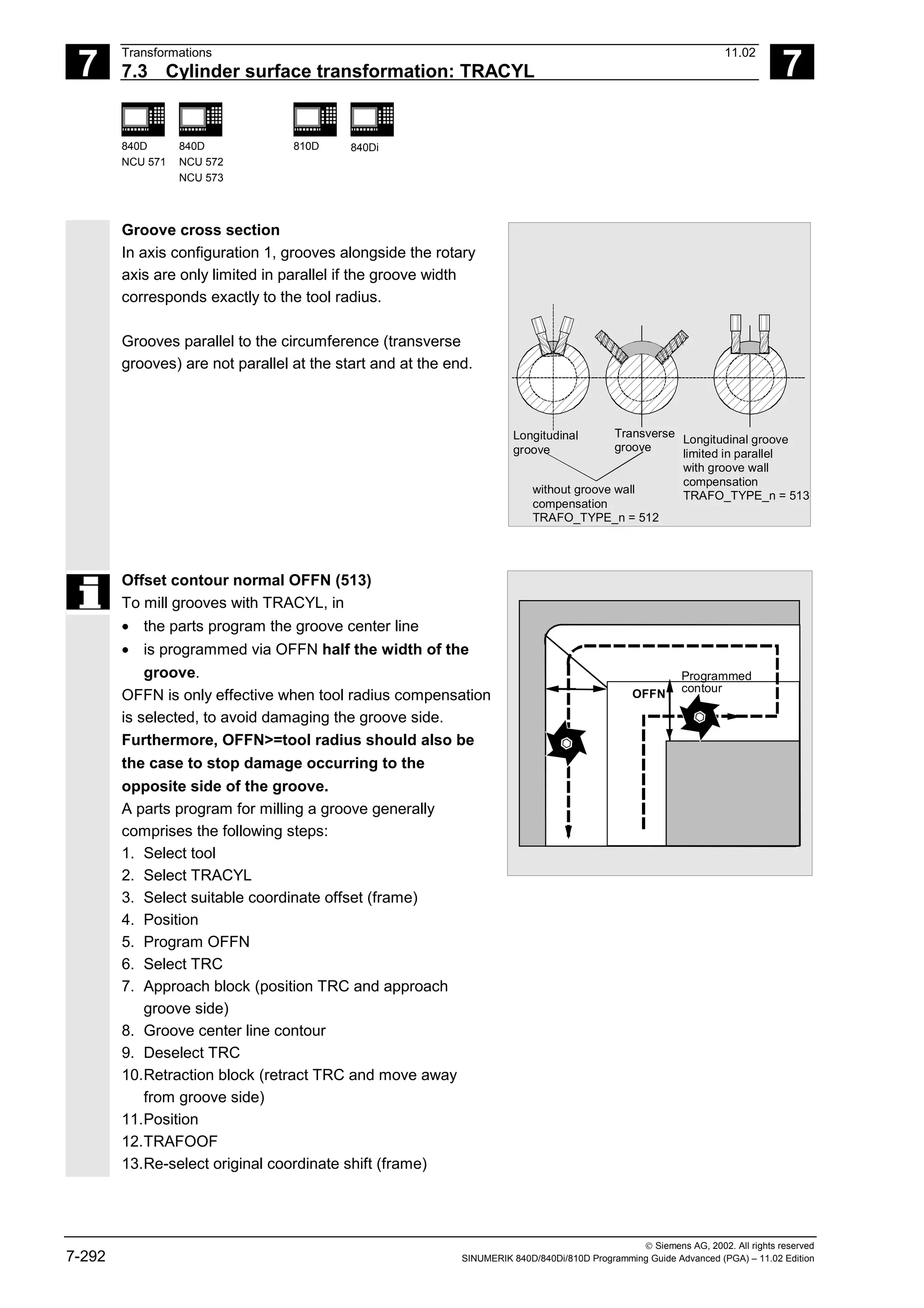
![7
Transformations 11.02
7.3 Cylinder surface transformation: TRACYL 7
840D
NCU 571
840D
NCU 572
NCU 573
810D 840Di
Siemens AG, 2002. All rights reserved
7-294 SINUMERIK 840D/840Di/810D Programming Guide Advanced (PGA) – 11.02 Edition
For cylinder peripheral curve transformation with
groove side compensation, the axis used for
compensation should be positioned at zero (y=0), so
that the groove centric to the programmed groove
center line is finished.
Rotary axis
The rotary axis cannot be programmed, as it is
assigned by a geometry axis and is thus not directly
programmable as a channel axis.
Axis utilization
The following axes cannot be used as a positioning
axis or a reciprocating axis:
• the geometry axis in the peripheral direction of
the cylinder peripheral surface (Y axis)
• the additional linear axis for groove side
compensation (Z axis).
Tool definition
The following example is suitable for testing the
parameterization of the TRACYL cylinder
transformation:
Tool parameters
number (DP)
Meaning Comment
$TC_DP1[1,1]=120 Tool type Milling cutter
$TC_DP2[1,1]=0 Tool point direction For turning tools only
Geometry Tool length compensation
$TC_DP3[1,1]=8. Length compensation vector Calculation depending
$TC_DP4[1,1]=9. on type and plane
$TC_DP5[1,1]=7.
Geometry Radius
$TC_DP6[1,1]=6. Radius Tool radius
$TC_DP7[1,1]=0 Slot width b for slotting saw, rounding radius
for milling tools
$TC_DP8[1,1]=0 Overhang k For slotting saw only
$TC_DP9[1,1]=0
$TC_DP10[1,1]=0
$TC_DP11[1,1]=0 Angle for cone milling tools
Wear Tool length and radius compensation
$TC_DP12[1,1]=0 Remaining parameters to $TC_DP24=0 Base dimensions/
adapter](https://image.slidesharecdn.com/fadaladvancedprogrammingmanual-220505063253/75/Fadal-Advanced-Programming-Manual-pdf-294-2048.jpg)
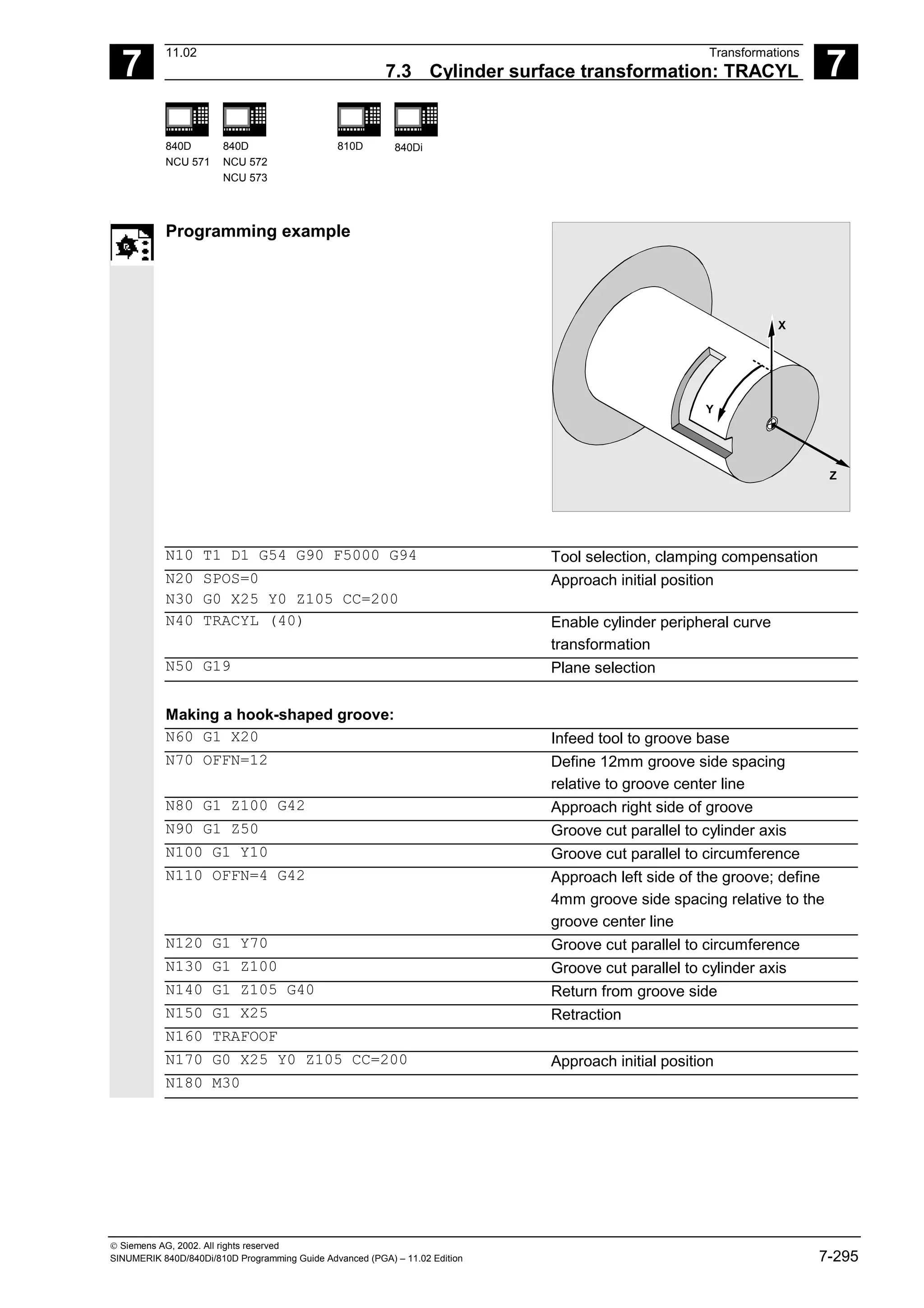
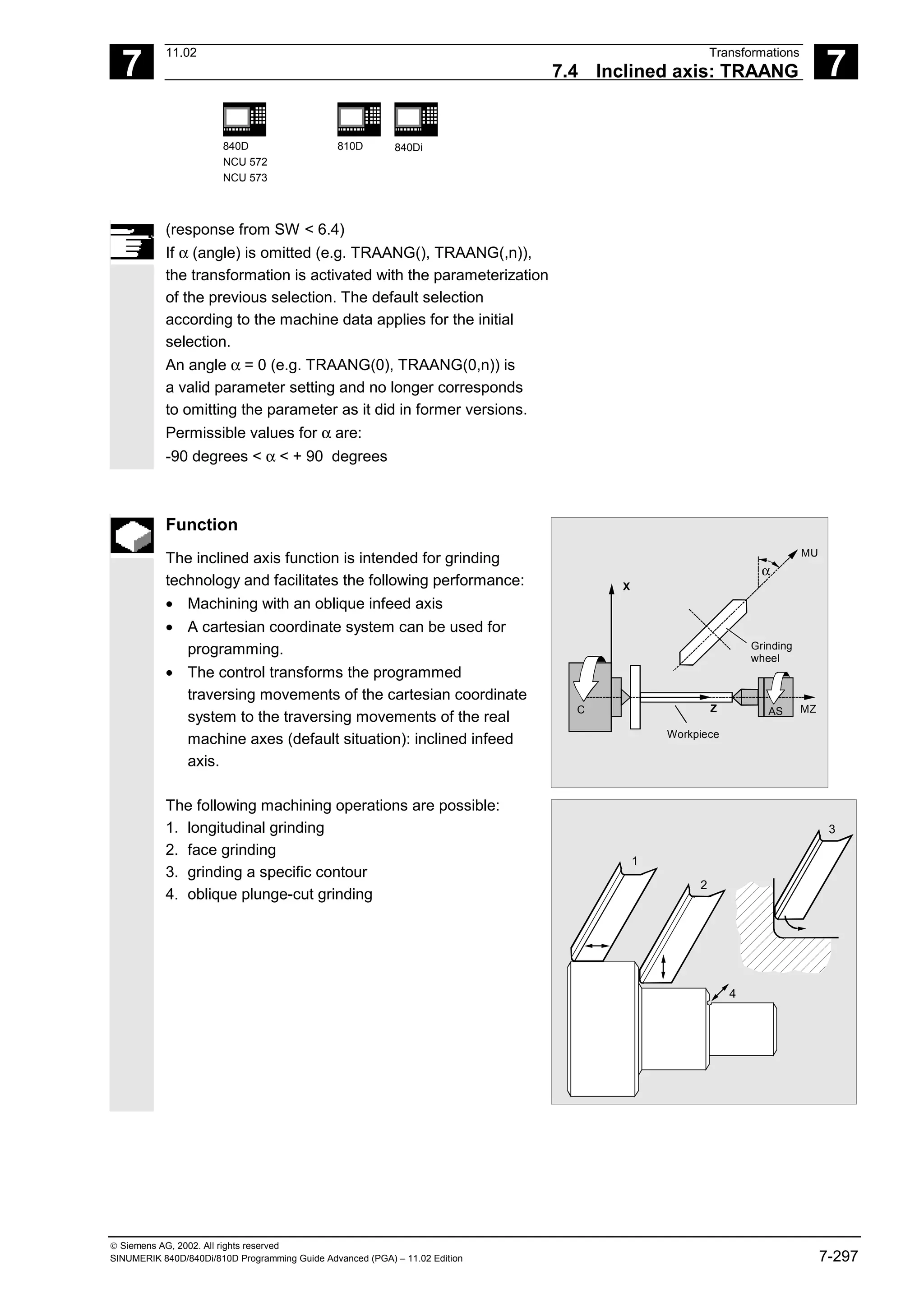
![7
11.02 Transformations
7.4 Inclined axis: TRAANG 7
840D
NCU 572
NCU 573
810D 840Di
Siemens AG, 2002. All rights reserved
SINUMERIK 840D/840Di/810D Programming Guide Advanced (PGA) – 11.02 Edition 7-299
Programming example
MU
α
AS MZ
C Z
X
Workpiece
Grinding
wheel
N10 G0 G90 Z0 MU=10 G54 F5000 ->
-> G18 G64 T1 D1
Tool selection, clamping compensation
Plane selection
N20 TRAANG(45) Enable inclined axis transformation
N30 G0 Z10 X5 Approach initial position
N40 WAITP(Z) Enable axis for reciprocation
N50 OSP[Z]=10 OSP2[Z]=5 OST1[Z]=–2 ->
-> OST2[Z]=–2 FA[Z]=5000
N60 OS[Z]=1
N70 POS[X]=4.5 FA[X]=50
N80 OS[Z]=0
Reciprocation, until dimension reached
(for reciprocation, see chapter 9)
N90 WAITP(Z) Enable reciprocating axes as positioning
axes
N100 TRAFOOF Switch off transformation
N110 G0 Z10 MU=10 Retraction
N120 M30
-> program in a single block](https://image.slidesharecdn.com/fadaladvancedprogrammingmanual-220505063253/75/Fadal-Advanced-Programming-Manual-pdf-299-2048.jpg)
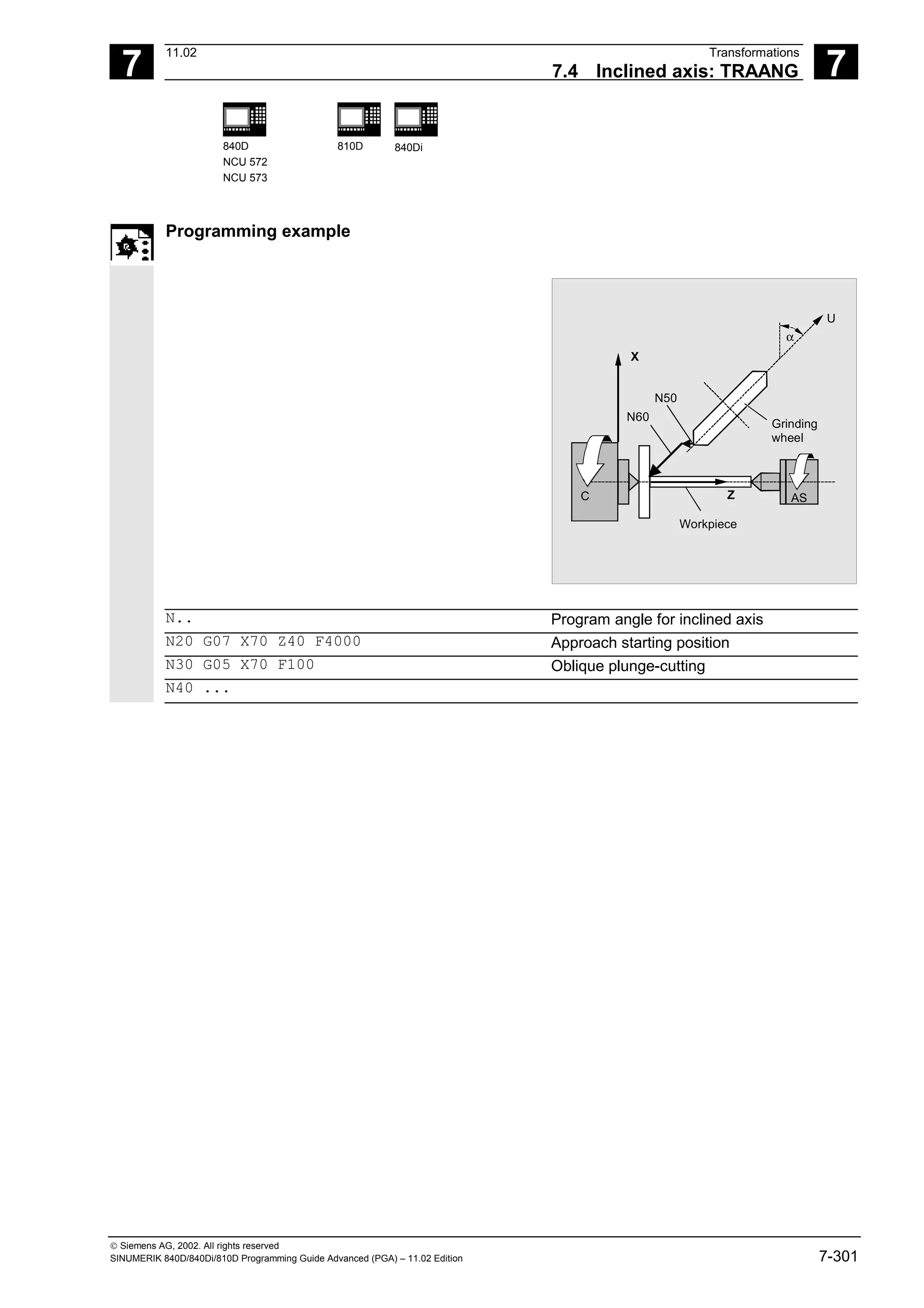
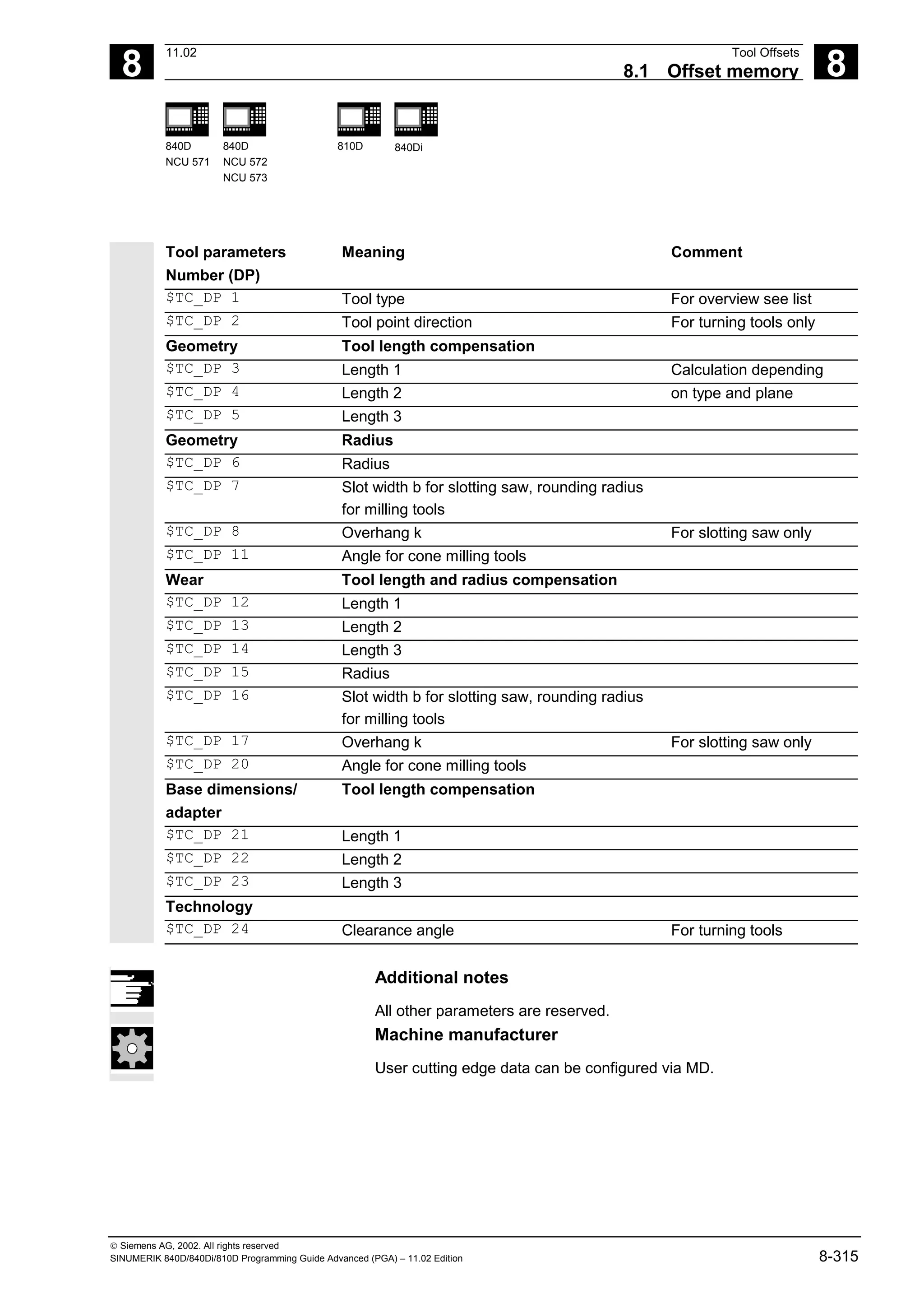
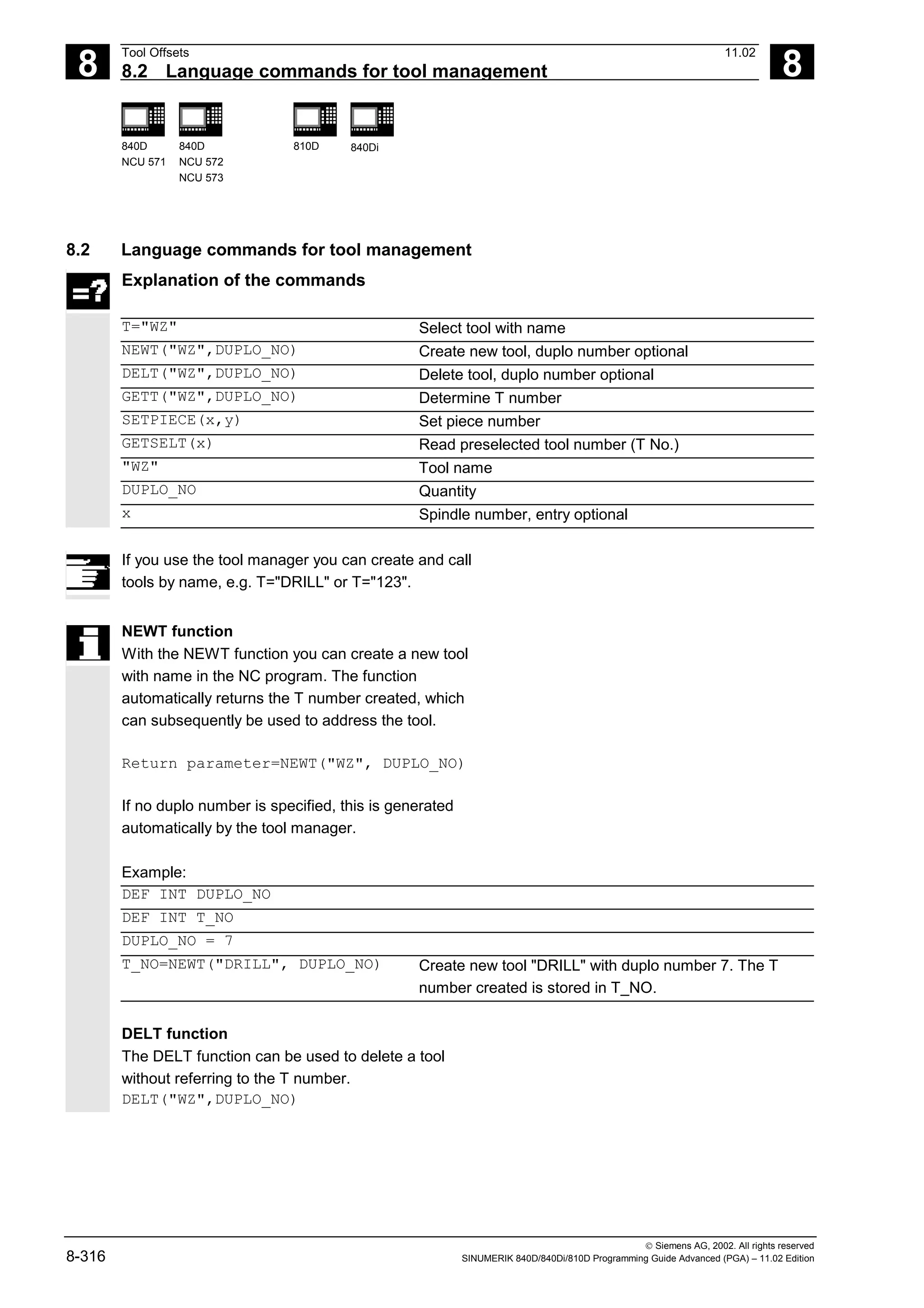
![8
11.02 Tool Offsets
8.2 Language commands for tool management 8
840D
NCU 571
840D
NCU 572
NCU 573
810D 840Di
Siemens AG, 2002. All rights reserved
SINUMERIK 840D/840Di/810D Programming Guide Advanced (PGA) – 11.02 Edition 8-317
GETT function
The GETT function returns the T number required to
set the tool data for a tool known only by its name.
Return parameter=GETT("WZ", DUPLO_NO)
If several tools with the specified name exist, the T
number of the first possible tool is returned.
Return parameter = –1: The tool name or duplo
number cannot be assigned to a tool.
Examples:
T="DRILL"
R10=GETT("DRILL", DUPLO_NO) Return T number for DRILL with duplo
number = DUPLO_NO
The "DRILL" must first be declared with NEWT or
$TC_TP1[ ].
$TC_DP1[GETT("DRILL",
DUPLO_NO),1]=100
Write a tool parameter with tool name
SETPIECE function
This function is used to update the piece number
monitoring data.
The function counts all of the tool edges which have
been changed since the last activation of SETPIECE
for the stated spindle number.
SETPIECE(x,y)
x Number of completed workpieces
y y spindle number, 0 stands for master spindle (default setting)](https://image.slidesharecdn.com/fadaladvancedprogrammingmanual-220505063253/75/Fadal-Advanced-Programming-Manual-pdf-317-2048.jpg)
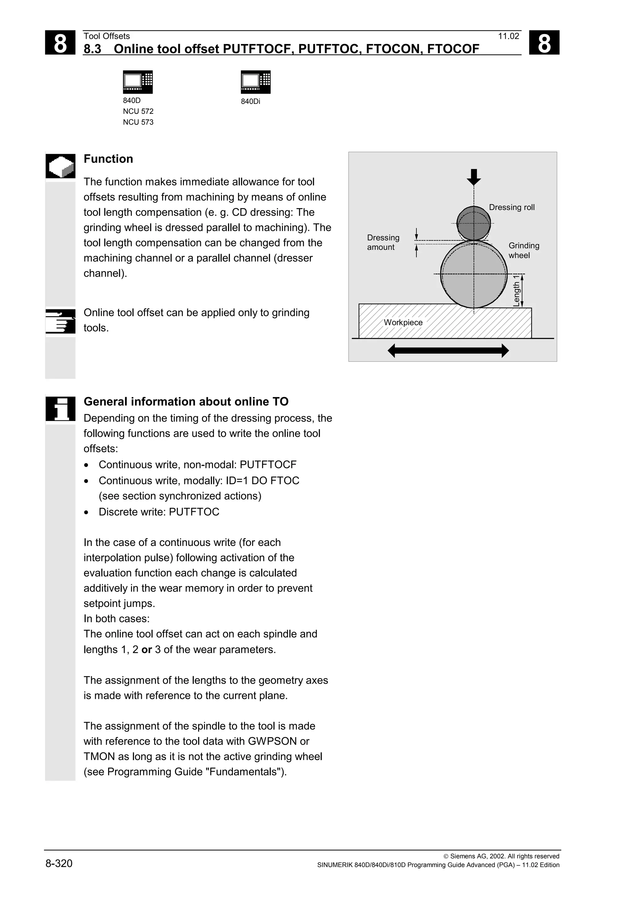
![8
Tool Offsets 11.02
8.3 Online tool offset PUTFTOCF, PUTFTOC, FTOCON, FTOCOF 8
840D
NCU 572
NCU 573
840Di
Siemens AG, 2002. All rights reserved
8-322 SINUMERIK 840D/840Di/810D Programming Guide Advanced (PGA) – 11.02 Edition
Set parameters for FCTDEF function
The parameters are defined in a separate block:
FCTDEF(Polynomial_NO., LLimit, ULimit,a0,a1,a2,a3)
The polynomial can be a 1st, 2nd or 3rd degree
polynomial.
The limit identifies the limit values (LLimit = lower
limit, ULimit = upper limit).
Example:
Straight line (y = a0 + a1x) with gradient 1
FCTDEF(1, -1000, 1000, -$AA_IW[X], 1)
Write online offset discretely: PUTFTOC
This command can be used to write an offset value
once. The offset is activated immediately on the
target channel.
Application of PUTFTOC:
The grinding wheel is dressed from a parallel
channel, but not at the same time as machining.
PUTFTOC(Value, Length1_2_3, Channel,
Spindle)
The online tool offset for the specified length 1, 2 or
3 is changed by the specified value, i.e. the value is
added to the wear parameter.
a0
a1
Y
X
1
Include online tool offset: FTOCON, FTOCOF
The target channel can only receive online tool
offsets when FTOCON is active.
• FTOCON must be written in the channel on
which the offset is to be activated.
With FTOCOF, the offset is no longer applied,
however the complete value written with
PUTFTOC is corrected in the tool edge-specific
offset data.
• FTOCOF is always the reset setting.
• PUTFTOCF always acts on the subsequent
traversing block.
• The online tool offset can also be selected modally
with FTOC. Please refer to Section "Motion-
synchronized actions" for more information.](https://image.slidesharecdn.com/fadaladvancedprogrammingmanual-220505063253/75/Fadal-Advanced-Programming-Manual-pdf-322-2048.jpg)
![8
11.02 Tool Offsets
8.3 Online tool offset PUTFTOCF, PUTFTOC, FTOCON, FTOCOF 8
840D
NCU 572
NCU 573
840Di
Siemens AG, 2002. All rights reserved
SINUMERIK 840D/840Di/810D Programming Guide Advanced (PGA) – 11.02 Edition 8-323
Programming example
Task
On a surface grinding machine with the following
parameters, the grinding wheel is to be dressed by
the amount 0.05 after the start of the grinding
movement at X100. The dressing amount is to be
active with write online offset continuously.
Y: Infeed axis for the grinding wheel
V: Infeed axis for the dresser roll
Machine: Channel 1 with axes X, Z, Y
Dress: Channel 2 with axis V
Dressing roll
Workpiece
Grinding
wheel
0.05
Y
X
100
Machining program in channel 1:
%_N_MACH_MPF
…
N110 G1 G18 F10 G90 Basic position
N120 T1 D1 Select current tool
N130 S100 M3 X100 Spindle on, travel to starting position
N140 INIT (2, "DRESS", "S") Select dressing program on channel 2
N150 START (2) Start dressing program on channel 2
N160 X200 Travel to destination position
N170 FTOCON Activate online offset
N… G1 X100 Continue machining
N…M30
Dressing program in channel 2:
%_N_DRESS_MPF
…
N40 FCTDEF (1, –1000, 1000, –$AA_IW[V], 1)Define function: Straight line
N50 PUTFTOCF (1, $AA_IW[V], 3, 1) Write online offset continuously:
Length 3 of the current grinding wheel is
derived from the movement of the V axis
and corrected in channel 1.
N60 V–0.05 G1 F0.01 G91 Infeed movement for dressing, PUTFTOCF
is only effective in this block
…
N… M30](https://image.slidesharecdn.com/fadaladvancedprogrammingmanual-220505063253/75/Fadal-Advanced-Programming-Manual-pdf-323-2048.jpg)
![8
Tool Offsets 11.02
8.3 Online tool offset PUTFTOCF, PUTFTOC, FTOCON, FTOCOF 8
840D
NCU 572
NCU 573
840Di
Siemens AG, 2002. All rights reserved
8-324 SINUMERIK 840D/840Di/810D Programming Guide Advanced (PGA) – 11.02 Edition
Dressing program, modal:
%_N_DRESS_MPF
FCTDEF(1,-1000,1000,-$AA_IW[V],1) Define function:
ID=1 DO FTOC(1,$AA_IW[V],3,1) Select online tool offset:
Actual value of the V axis is the input value
for polynomial 1; the result is added length 3
of the active grinding wheel in channel 1 as
the offset value.
WAITM(1,1,2) Synchronization with machining channel
G1 V-0.05 F0.01, G91 Infeed movement for dressing
G1 V-0.05 F0.02
...
CANCEL(1) Deselect online offset
...](https://image.slidesharecdn.com/fadaladvancedprogrammingmanual-220505063253/75/Fadal-Advanced-Programming-Manual-pdf-324-2048.jpg)
![8
Tool Offsets 11.02
8.4 Maintain tool radius compensation at constant level, CUTCONON 8
840D
NCU 572
NCU 573
840Di
Siemens AG, 2002. All rights reserved
8-326 SINUMERIK 840D/840Di/810D Programming Guide Advanced (PGA) – 11.02 Edition
They are displaced, however, by the vector from the
end point of the last compensation block to its offset
point.
The interpolation type of these blocks (linear,
circular, polynomial) is arbitrary.
The deactivation block of the compensation
suppression, i.e. the block containing CUTCONOF,
is usually corrected; it begins at the offset point of
the start point.
A linear block is inserted between this point and the
end point of the previous block, i.e. the last
programmed motion block with active CUTCONON.
Circle blocks in which the circle plane is
perpendicular to the compensation plane (vertical
circles) are treated as if CUTCONON had been
programmed in the blocks.
This implicit activation of compensation suppression
is automatically canceled in the first motion block
which is not a circle of this type but which contains a
traversing movement in the compensation plane.
Vertical circles of this type can only occur with
circumferential milling.
Example
N10 ; Definition of tool d1
N20 $TC_DP1[1,1]= 110 ; Type
N30 $TC_DP6[1,1]= 10. ; Radius
N40
N50 X0 Y0 Z0 G1 G17 T1 D1 F10000
N60
N70 X20 G42 NORM
N80 X30
N90 Y20
N100 X10 CUTCONON; Activate compensation suppression
N110 Y30 CONT ; Insert bypass circle if necessary on deactivation
of contour suppression
N120 X-10 CUTCONOF
N130 Y20 NORM ; No bypass circle on deactivation of TRC
N140 X0 Y0 G40
N150 M30](https://image.slidesharecdn.com/fadaladvancedprogrammingmanual-220505063253/75/Fadal-Advanced-Programming-Manual-pdf-326-2048.jpg)
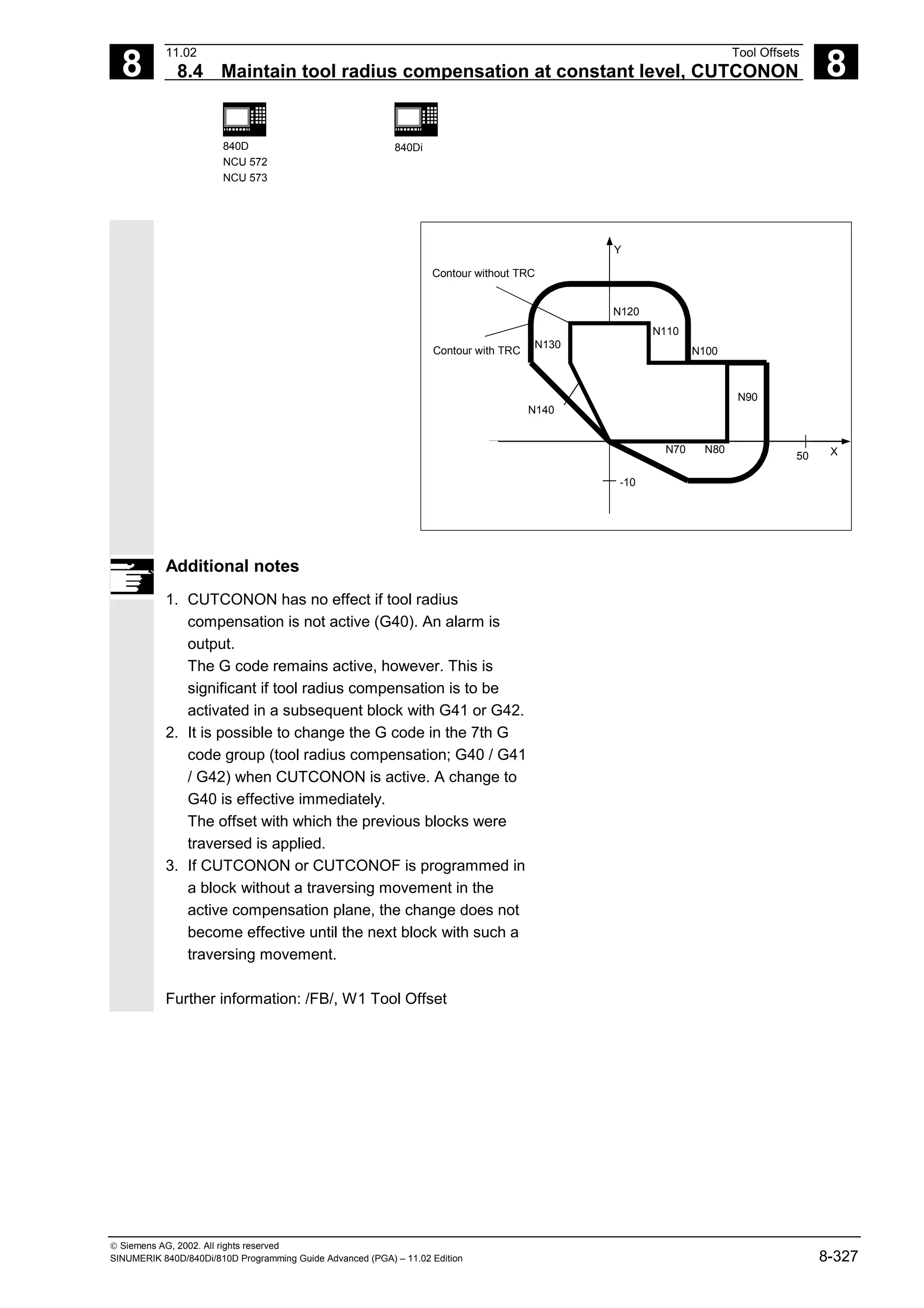
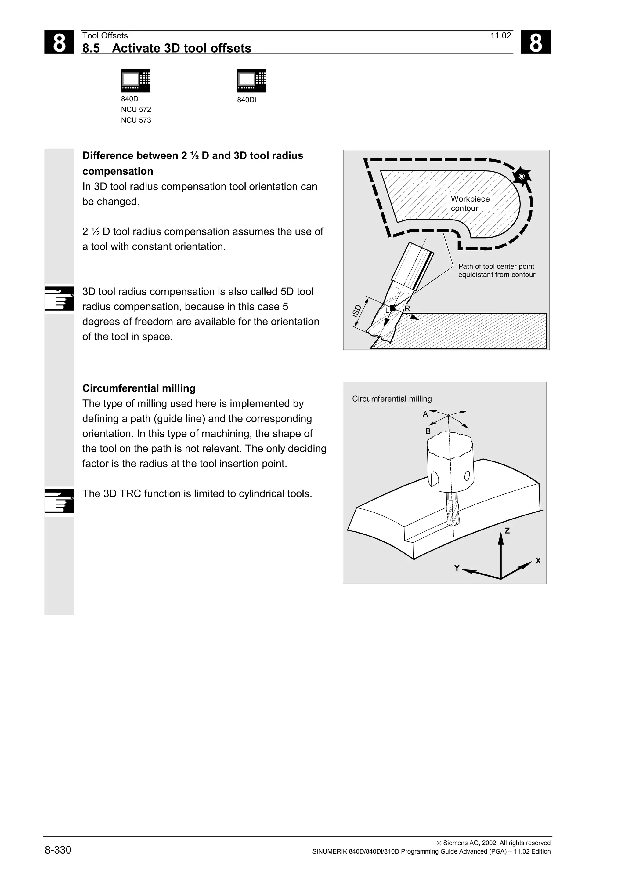
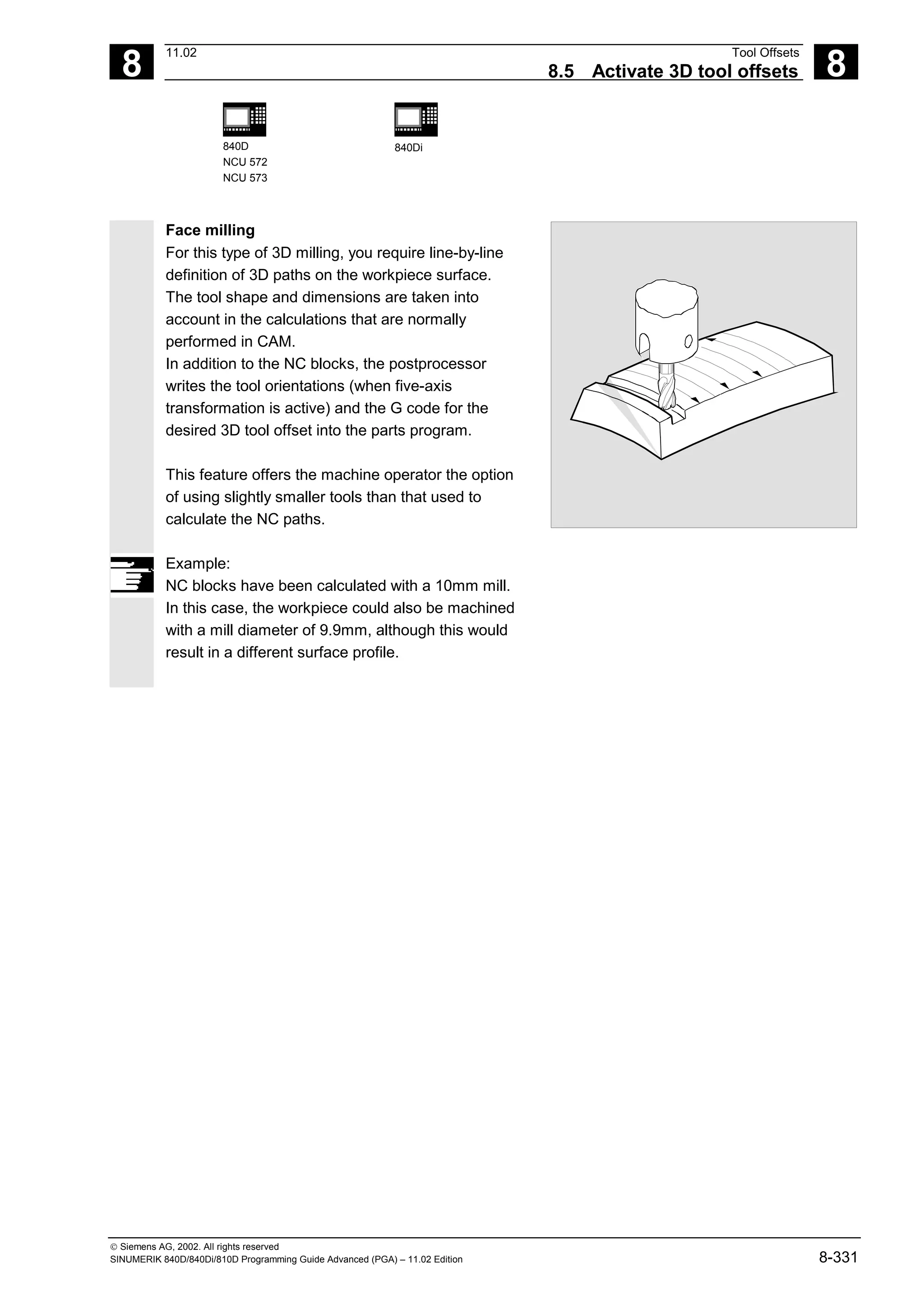
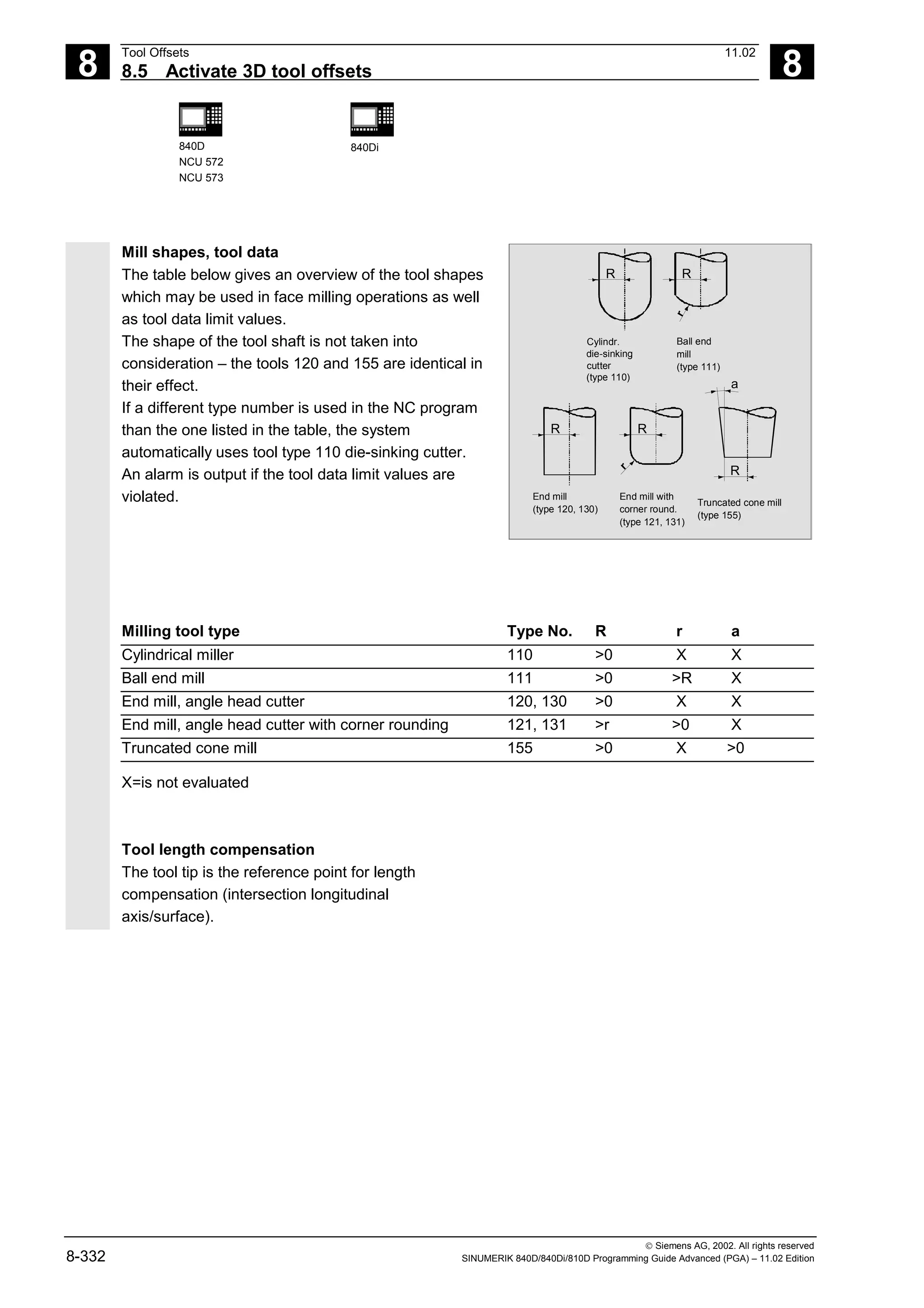
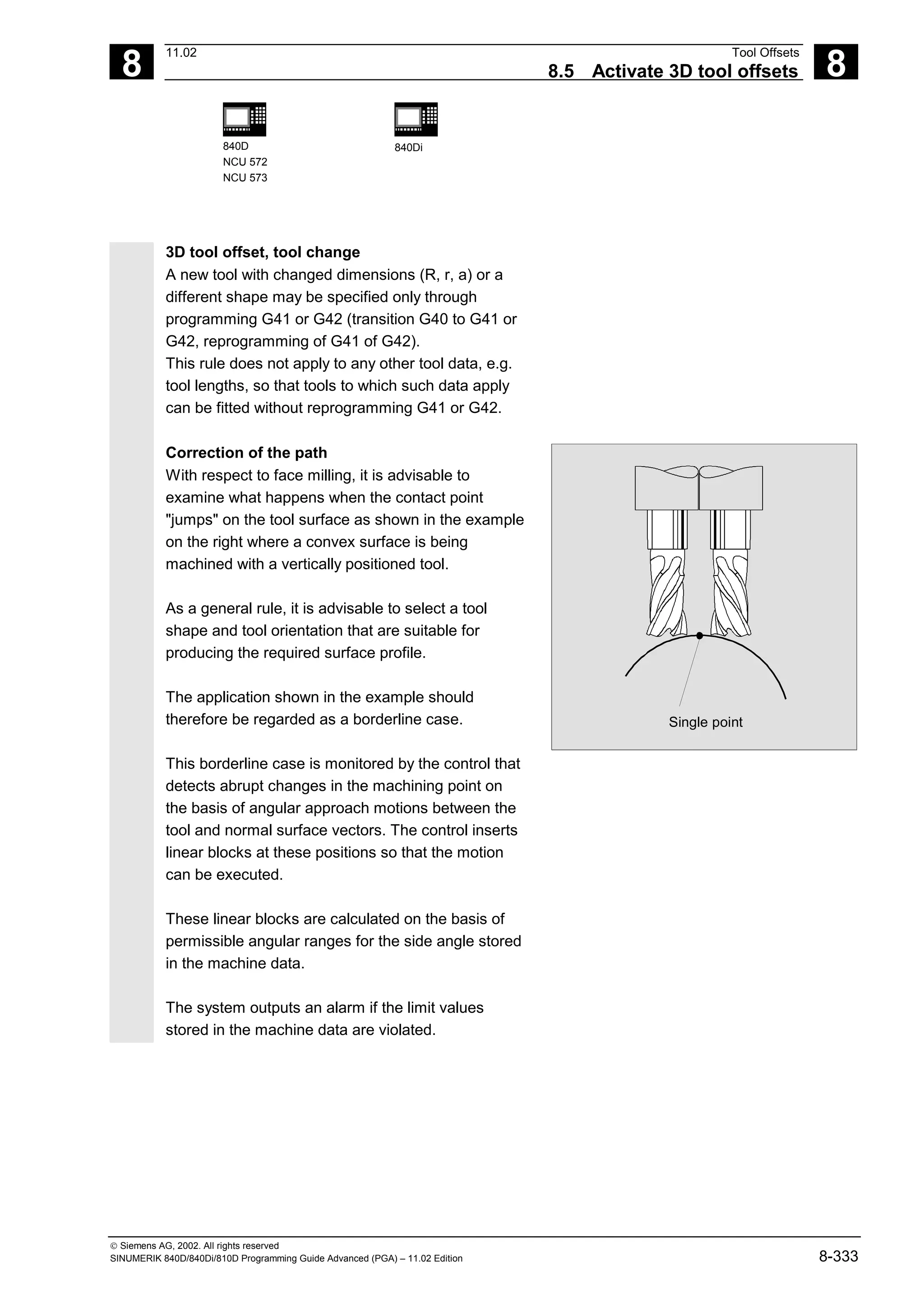
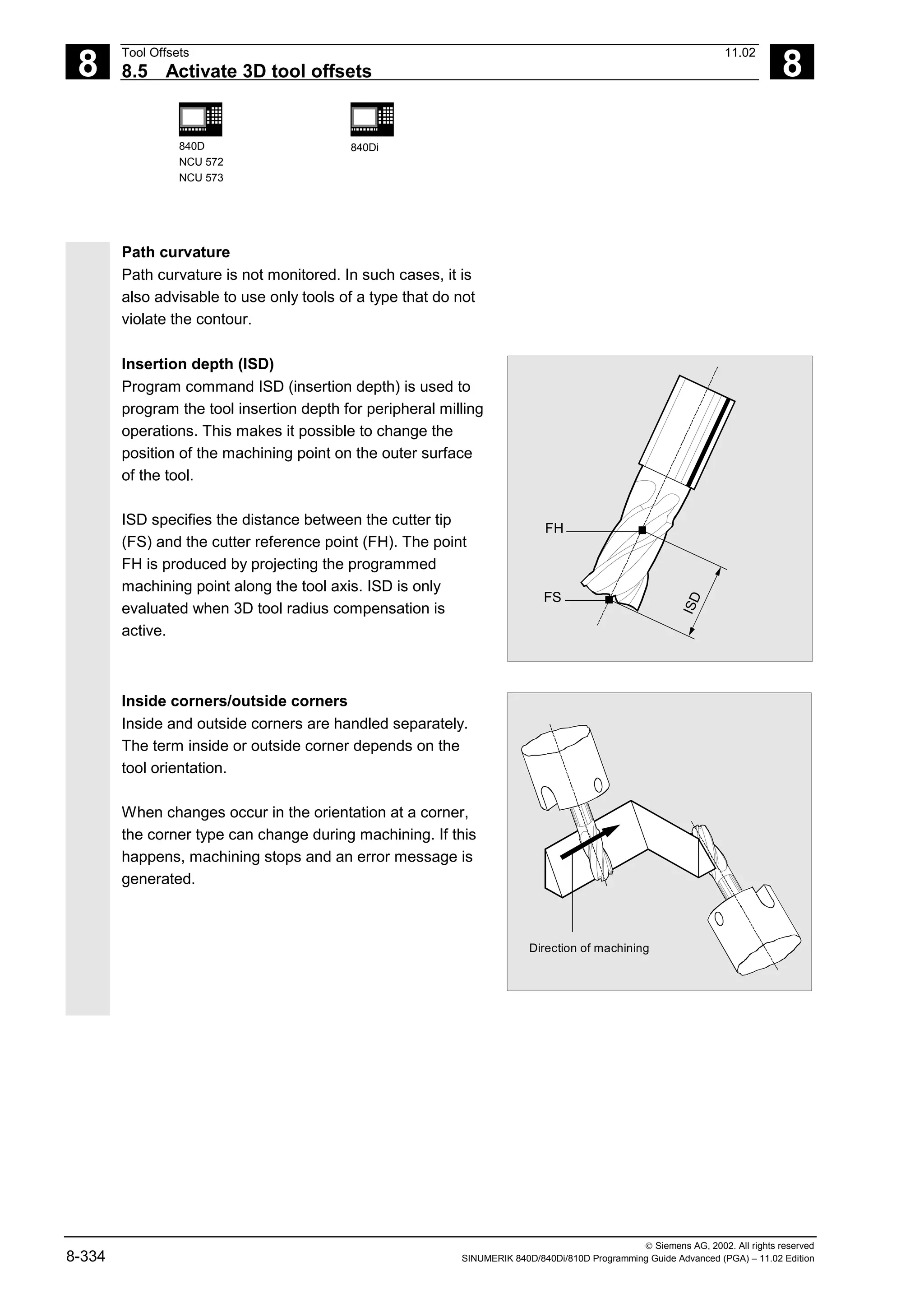
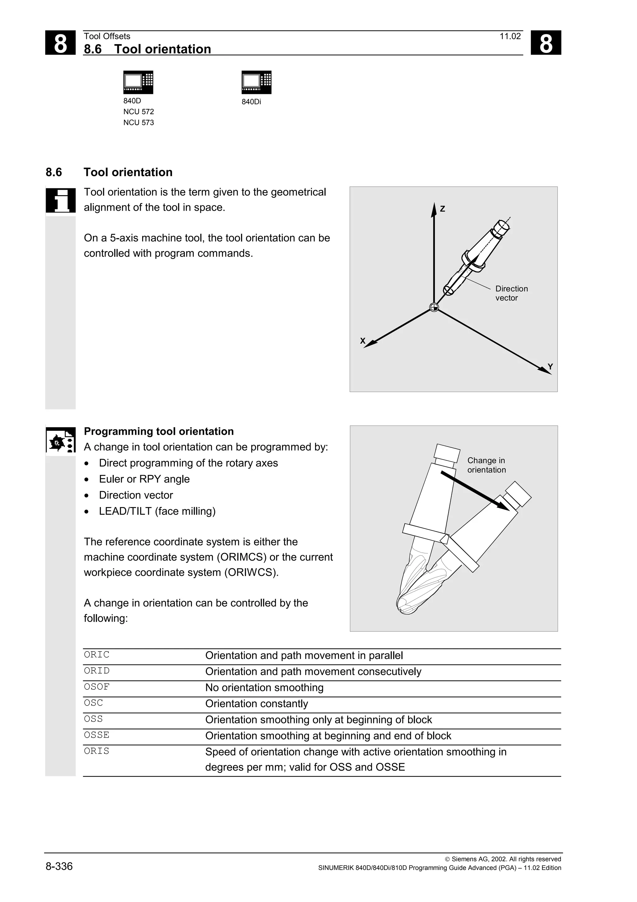
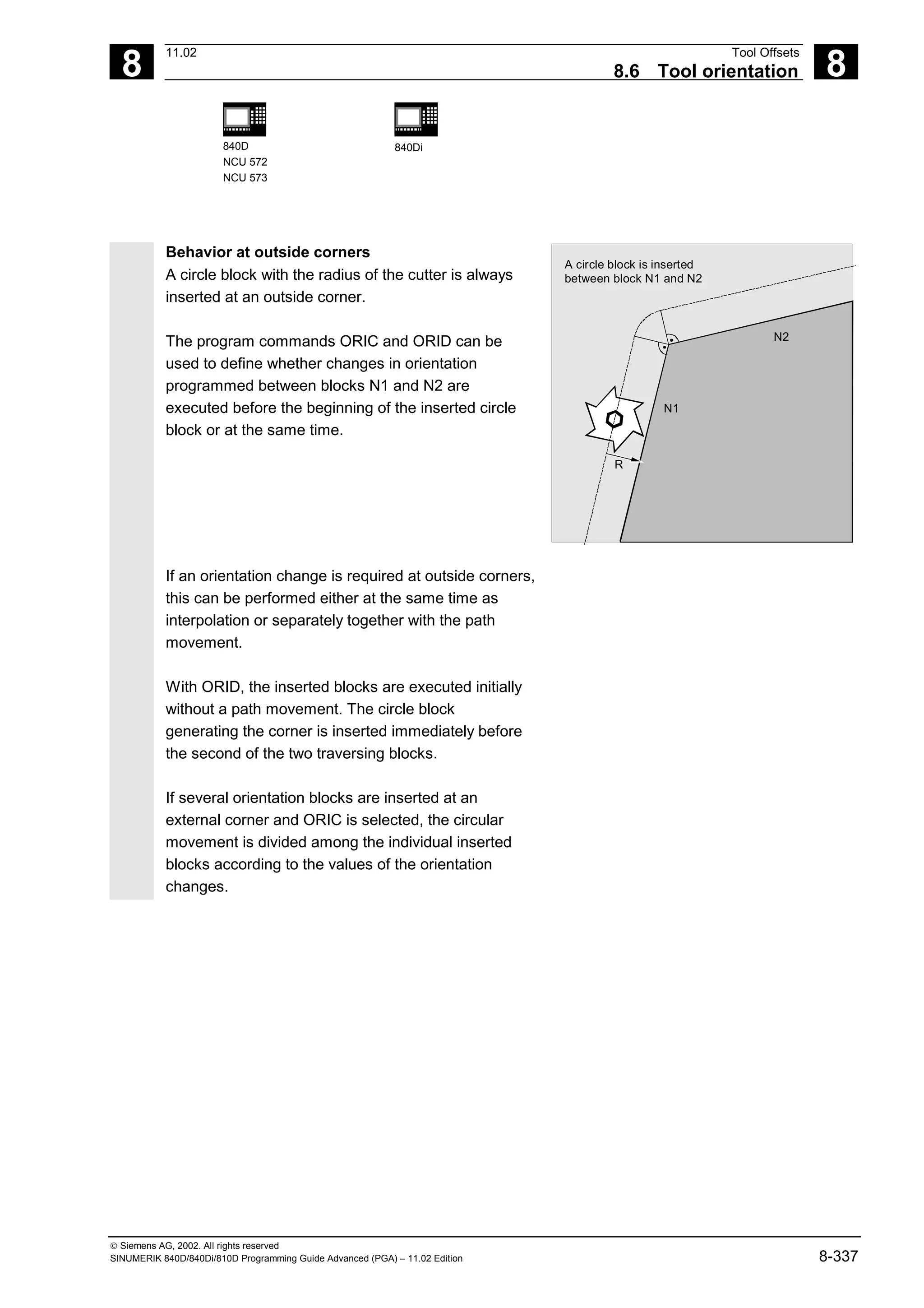
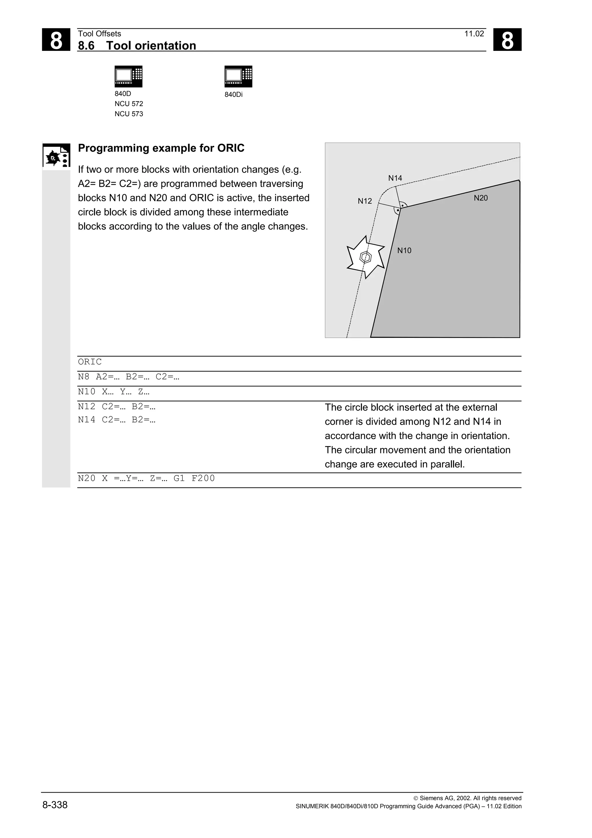
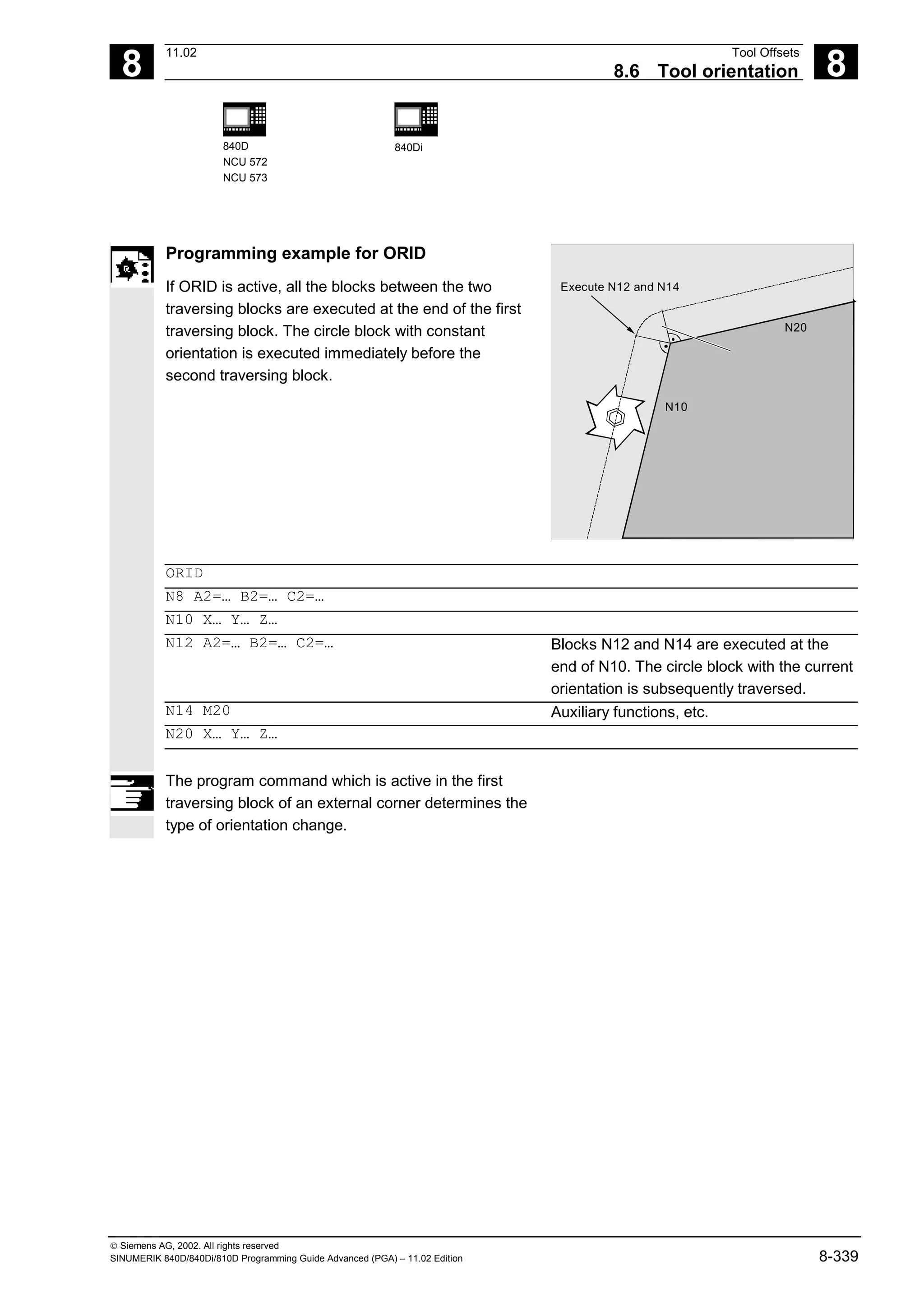
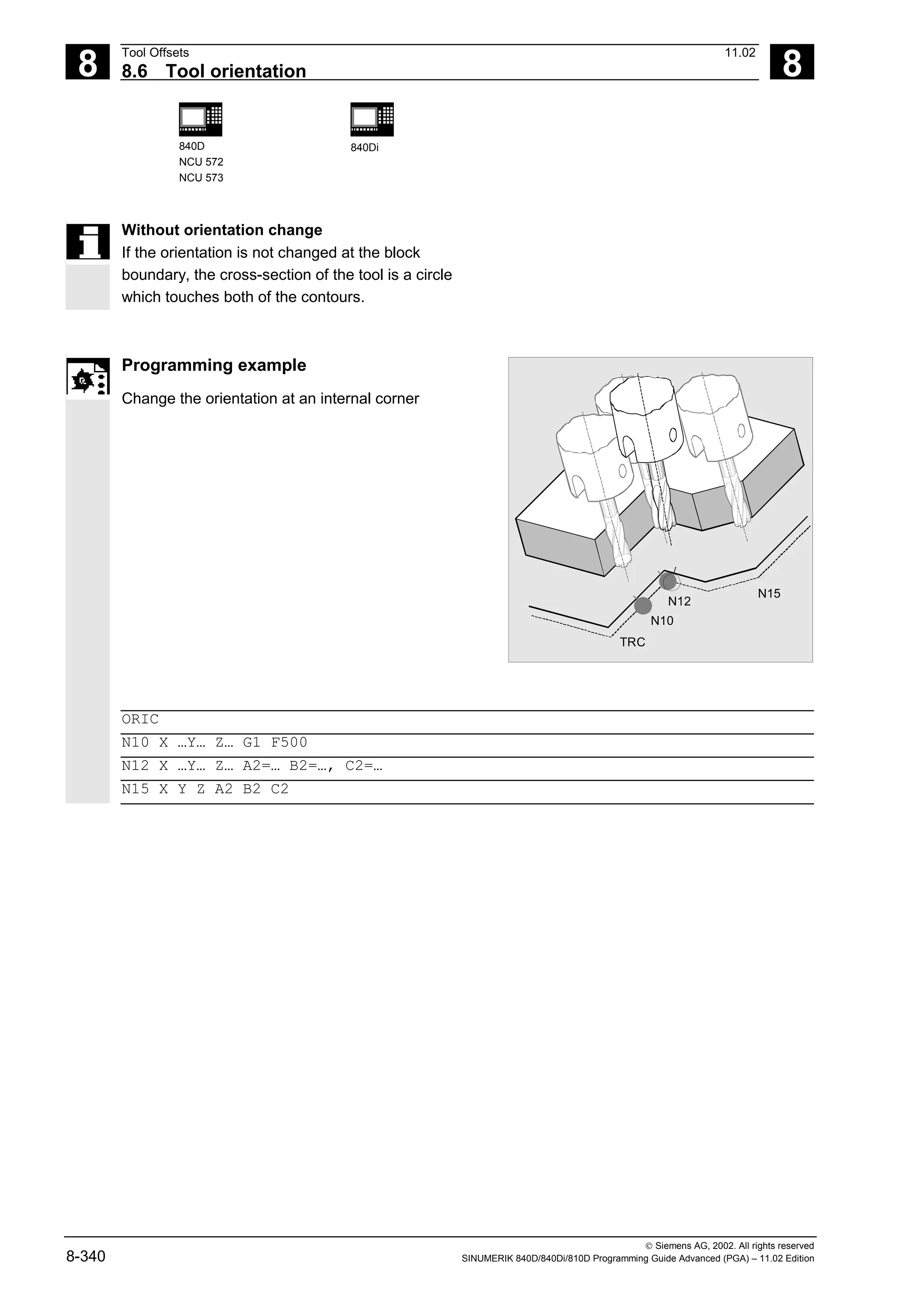

![8
11.02 Tool Offsets
8.7 Free assignment of D numbers, cutting edge number CE 8
840D
NCU 572
NCU 573
840Di
Siemens AG, 2002. All rights reserved
SINUMERIK 840D/840Di/810D Programming Guide Advanced (PGA) – 11.02 Edition 8-343
8.7.2 Renaming D numbers (GETDNO, SETDNO)
Programming:
d = GETDNO(t,ce)
state = SETDNO(t,ce,d)
Explanation of the parameters
d D number of the cutting edge of the tool
t T number of the tool
ce Cutting edge number (CE number) of the tool
state Indicates whether the command could be executed (TRUE or FALSE).
Function
GETDNO
This command returns the D number of a particular
cutting edge (ce) of a tool with tool number t.
If there is no D number for the specified parameters,
d is set to 0. If the D number is invalid, a value
greater than 32000 is returned.
SETDNO
This commands assigns the value d of the D number
to a cutting edge ce of tool t. The result of this
statement is returned via state (TRUE or FALSE)
If there is no data block for the specified parameter,
the value FALSE is returned. Syntax errors produce
an alarm. The D number cannot be set to 0 explicitly.
Example: (renaming a D number)
$TC_DP2[1,2] = 120
$TC_DP3[1,2] = 5.5
$TC_DPCE[1,2] = 3; cutting edge
number CE
...
N10 def int DNoOld, DNoNew = 17
N20 DNoOld = GETDNO(1,3)
N30 SETDNO(1,3,DNoNew)](https://image.slidesharecdn.com/fadaladvancedprogrammingmanual-220505063253/75/Fadal-Advanced-Programming-Manual-pdf-343-2048.jpg)
![8
Tool Offsets 11.02
8.8 Toolholder kinematics 8
840D
NCU 572
NCU 573
840Di
Siemens AG, 2002. All rights reserved
8-346 SINUMERIK 840D/840Di/810D Programming Guide Advanced (PGA) – 11.02 Edition
8.8 Toolholder kinematics
The toolholder kinematics with up to two rotary axes is
programmed by means of 17 system variables
$TC_CARR1[m] to $TC_CARR17[m]. The description
of the toolholder consists of:
• The vectorial distance between the first rotary axis
and the toolholder reference point l1, the vectorial
distance between the first and the second rotary
axis l2, the vectorial distance between the second
rotary axis and the tool reference point l3.
• The reference vectors of both rotary axes v1, v2.
• The rotation angles α1, α2 around both axes. The
rotation angles are counted in viewing direction of
the rotary axis vectors, positive, in clockwise
direction of rotation.
Resolved kinematics as of SW 5.3
For machines with resolved kinematics (both the tool
and the part can rotate), the system variables have
been extended to include the entries $TC_CARR18[m]
to $TC_CARR23[m] are described as follows:
The rotatable tool table consisting of:
• The vector distance between the second rotary axis
v2 and the reference point of a rotatable tool table l4
of the third rotary axis.
The rotary axes consisting of:
• The two channel identifiers for the reference to the
rotary axes v1 and v2. These positions are accessed
as required to determine the orientation of the
orientable toolholder.
The type of kinematics with one of the values T, P or M:
• Type of kinematics T: Only tool can rotate.
• Type of kinematics P: Only part can rotate.
• Type of kinematics M: Tool and part can rotate.
V1
V2
α
1
α
2
l1
l2
l3](https://image.slidesharecdn.com/fadaladvancedprogrammingmanual-220505063253/75/Fadal-Advanced-Programming-Manual-pdf-346-2048.jpg)
![8
11.02 Tool Offsets
8.8 Toolholder kinematics 8
840D
NCU 572
NCU 573
840Di
Siemens AG, 2002. All rights reserved
SINUMERIK 840D/840Di/810D Programming Guide Advanced (PGA) – 11.02 Edition 8-347
Function of the system parameter for orientable toolholders
Designation x components y components z components
l1 offset vector $TC_CARR1[m] $TC_CARR2[m] $TC_CARR3[m]
l2 offset vector $TC_CARR4[m] $TC_CARR5[m] $TC_CARR6[m]
v1 rotary axis $TC_CARR7[m] $TC_CARR8[m] $TC_CARR9[m]
v2 rotary axis $TC_CARR10[m] $TC_CARR11[m] $TC_CARR12[m]
α1 rotation angle
α2 rotation angle
$TC_CARR13[m]
$TC_CARR14[m]
l3 offset vector $TC_CARR15[m] $TC_CARR16[m] $TC_CARR17[m]
l4 offset vector $TC_CARR18[m] $TC_CARR19[m] $TC_CARR20[m]
Axis identifier
for rotary axis v1
for rotary axis v2
Axis identifier for rotary axes v1 and v2 (default is zero)
$TC_CARR21[m]
$TC_CARR22[m]
$TC_CARR23[m]
Type of kinematics T ð Type of kinematics P ð Type of Kinematics M
Type of
kinematics
Default T Only the Tool can be
rotated
Only the Part can be
rotated
Part and tool Mixed
mode can be rotated
Offset for
rotary axis v1
rotary axis v2
Angle in degrees of rotary axes v1 and v2 when assuming the initial setting
$TC_CARR24[m]
$TC_CARR25[m]
Angle offset for
rotary axis v1
rotary axis v2
Offset of Hirth tooth system in degrees for rotary axes v1 and v2
$TC_CARR26[m]
$TC_CARR27[m]
Angle increment
v1 rotary axis
v2 rotary axis
Increment of Hirth tooth system in degrees for rotary axes v1 and v2
$TC_CARR28[m]
$TC_CARR29[m]
Minimum position
rotary axis v1
rotary axis v2
Software limit for minimum position for rotary axes v1 and v2
$TC_CARR30[m]
$TC_CARR31[m]
Maximum
position
rotary axis v1
rotary axis v2
Software limits for maximum position for rotary axes v1 and v2
$TC_CARR32[m]
$TC_CARR33[m]](https://image.slidesharecdn.com/fadaladvancedprogrammingmanual-220505063253/75/Fadal-Advanced-Programming-Manual-pdf-347-2048.jpg)
![8
Tool Offsets 11.02
8.8 Toolholder kinematics 8
840D
NCU 572
NCU 573
840Di
Siemens AG, 2002. All rights reserved
8-348 SINUMERIK 840D/840Di/810D Programming Guide Advanced (PGA) – 11.02 Edition
Parameters of the rotary axes from SW 6.1
The system variables are extended by the entries
$TC_CARR24[m] to $TC_CARR33[m] and described
as follows:
The offset of the rotary axes
• Changing the position of rotary axis v1 or v2 during
initial setting of the orientable toolholder.
The angle offset/angle increment of the rotary axes
• Offset or angle increment of Hirth tooth system of
rotary axes v1 and v2. Programmed or calculated
angle is rounded up to the next value that results
from phi = s + n * d when n is an integer.
The minimum position/maximum position of the
rotary axis
• Limit angle (software limit) for rotary axis v1 and v2.
Additional notes
The number of the respective toolholder to be
programmed is specified with "m.
The start/endpoints of the distance vectors on the axes
can be freely selected. The rotation angles α1, α2
around the two axes are defined in the initial state of
the toolholder by 0°. In this way, the kinematics of a
toolholder can be programmed for any number of
possibilities.
Toolholders with only one or no rotary axis at all can
be described by setting the direction vectors of one
or both rotary axes to zero. With a toolholder without
rotary axis the distance vectors act as additional tool
offsets whose components cannot be affected by a
change of machining plane (G17 to G19).](https://image.slidesharecdn.com/fadaladvancedprogrammingmanual-220505063253/75/Fadal-Advanced-Programming-Manual-pdf-348-2048.jpg)
![8
11.02 Tool Offsets
8.8 Toolholder kinematics 8
840D
NCU 572
NCU 573
840Di
Siemens AG, 2002. All rights reserved
SINUMERIK 840D/840Di/810D Programming Guide Advanced (PGA) – 11.02 Edition 8-349
Clearing the toolholder data
The data of all toolholder data sets is cleared via
$TC_CARR1[0] = 0.
SW 5.3 and higher
The type of kinematics $TC_CARR23[T] = T must
be assigned one of the three permissible uppercase
or lowercase letter (T,P,M) and should not be
deleted.
Changing the toolholder data
Each of the described values can be modified by
assigning a new value in the parts program.
Any character other than T, P or M causes an alarm
when you attempt to activate the orientable
toolholder.
Reading the toolholder data
Each of the described values can be read by
assigning it to a variable in the parts program.
Supplementary conditions
A toolholder can only orientate a tool in every possible
direction in space if
- two rotary axes v1 and v2 are available.
- the rotary axes are positioned perpendicular to one
another.
- the tool length axis is perpendicular to the
second rotary axis v2.
SW 5.3 and higher
In addition, the following requirement is applicable to
machines for which all possible orientations have to
be settable:
- Tool orientation must be perpendicular to the first
rotary axis v1.](https://image.slidesharecdn.com/fadaladvancedprogrammingmanual-220505063253/75/Fadal-Advanced-Programming-Manual-pdf-349-2048.jpg)
![8
Tool Offsets 11.02
8.8 Toolholder kinematics 8
840D
NCU 572
NCU 573
840Di
Siemens AG, 2002. All rights reserved
8-350 SINUMERIK 840D/840Di/810D Programming Guide Advanced (PGA) – 11.02 Edition
Programming example
The toolholder used in the following example can be
fully described by a rotation around the Y axis. z
Y
Y
X
X
Z
z
Y
X
X
Z
N10 $TC_CARR8[1]=1 Definition of the Y components of the first
rotary axis of toolholder 1
N20 $TC_DP1[1,1]=120 Definition of an end mill
N30 $TC_DP3[1,1]=20 with length 20mm
N40 $TC_DP6[1,1]=5 and with radius 5mm
N50 ROT Y37 Frame definition with 37° rotation around the
Y axis
N60 X0 Y0 Z0 F10000 Approach initial position
N70 G42 CUT2DF TCOFR TCARR=1 T1 D1 X10 Set radius compensation, tool length
compensation in rotated frame, select
toolholder 1, tool 1
N80 X40 Execute machining under a 37° rotation
N90 Y40
N100 X0
N110 Y0
N120 M30
■](https://image.slidesharecdn.com/fadaladvancedprogrammingmanual-220505063253/75/Fadal-Advanced-Programming-Manual-pdf-350-2048.jpg)
![9
Path Traversing Behavior 11.02
9.1 Tangential control TANG, TANGON, TANGOF, TANGDEL 9
840D
NCU 572
NCU 573
810D 840Di
Siemens AG, 2002. All rights reserved
9-352 SINUMERIK 840D/840Di/810D Programming Guide Advanced (PGA) – 11.02 Edition
9.1 Tangential control TANG, TANGON, TANGOF, TANGDEL
Programming
TANG (FAxisF,LAxis1,LAxis2,Coupling,CS)
TANGON (FAxis,Angle)
TANGOF (FAxis)
TLIFT (FAxis)
TANGDEL (FAxis)
Explanation of the commands
TANG Preparatory instruction for the definition of a tangential follow-up
TANGON Activate tangential control specifying following axis and offset angle
TANGOF Deactivate tangential control specifying following axis
TLIFT Insert intermediate block at contour corners
TANGDEL Delete definition of a tangential follow-up
Explanation of the parameters
FAxis Following axis: additional tangential following rotary axis
LAxis1, LAxis2 Leading axes: path axes which determine the tangent for the following axis
Coupling Coupling factor: relationship between the angle change of the tangent
and the following axis.
Parameter optional; default: 1
CS Identifier for coordinate system
"B" = basic coordinate system; data optional; default
["W" = workpiece coordinate system]
Angle Offset angle of following axis](https://image.slidesharecdn.com/fadaladvancedprogrammingmanual-220505063253/75/Fadal-Advanced-Programming-Manual-pdf-352-2048.jpg)
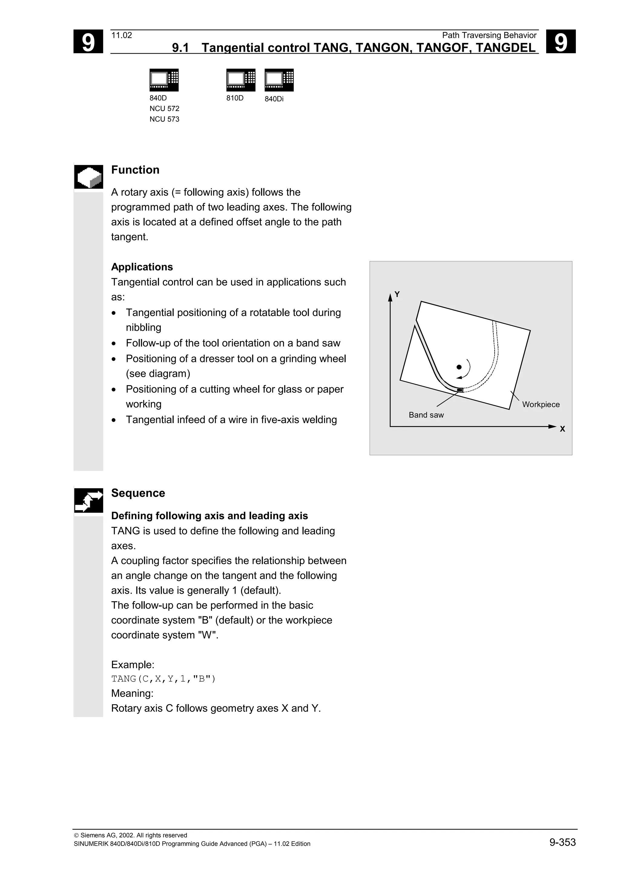
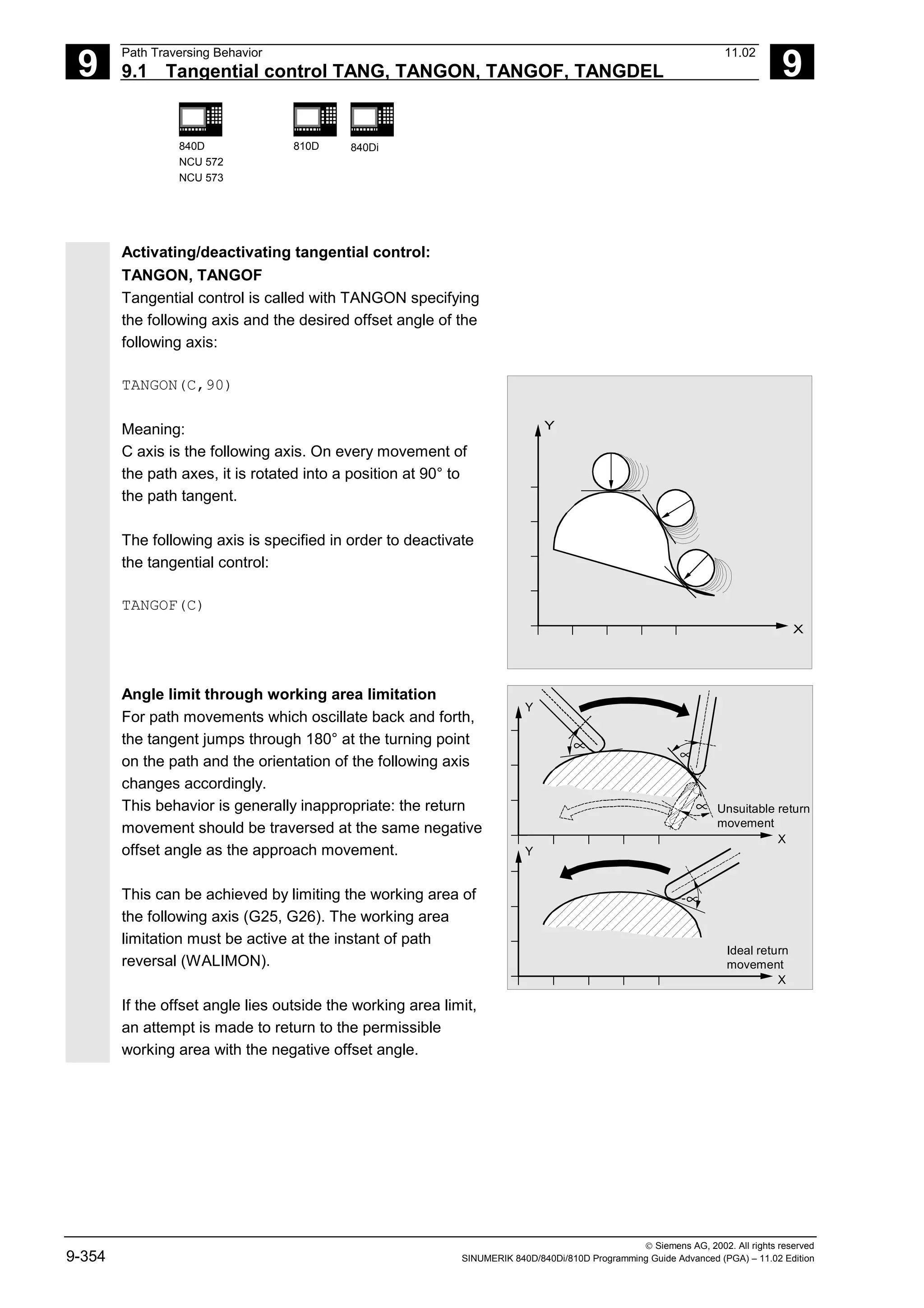
![9
11.02 Path Traversing Behavior
9.1 Tangential control TANG, TANGON, TANGOF, TANGDEL 9
840D
NCU 572
NCU 573
810D 840Di
Siemens AG, 2002. All rights reserved
SINUMERIK 840D/840Di/810D Programming Guide Advanced (PGA) – 11.02 Edition 9-357
Additional notes
Influence on transformations
The position of the following rotary axis can be an
input value for a transformation.
Explicit positioning of the following axis
If an axis which is following your lead axes is
positioned explicitly the position is added to the
programmed offset angle.
All path definitions are possible: Path and positioning
axis movements.
Coupling status
You can query the status of the coupling in the NC
program with the following system variable:
$AA_COUP_ACT[Axis]
0 No coupling active
1,2,3 Tangential follow-up active](https://image.slidesharecdn.com/fadaladvancedprogrammingmanual-220505063253/75/Fadal-Advanced-Programming-Manual-pdf-357-2048.jpg)
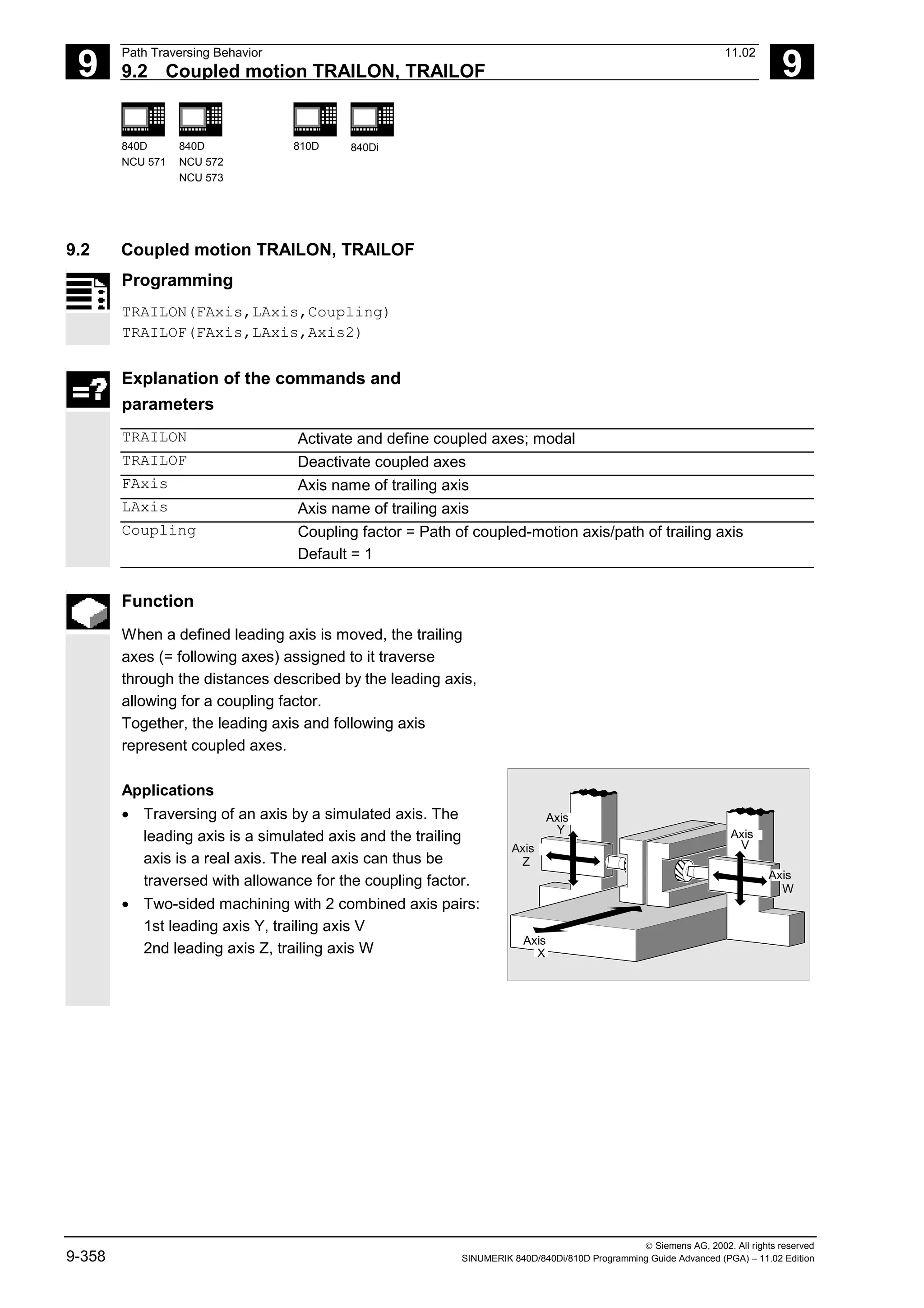
![9
11.02 Path Traversing Behavior
9.2 Coupled motion TRAILON, TRAILOF 9
840D
NCU 571
840D
NCU 572
NCU 573
810D 840Di
Siemens AG, 2002. All rights reserved
SINUMERIK 840D/840Di/810D Programming Guide Advanced (PGA) – 11.02 Edition 9-361
Additional notes
Acceleration and velocity
The acceleration and velocity limits of the combined
axes are determined by the "weakest axis" in the
combined axis pair.
Coupling status
You can query the status of the coupling in the NC
program with the following system variable:
$AA_COUP_ACT[axis]
0 No coupling active
8 Coupled motion active
Programming example
The workpiece is to be machined on two sides with
the axis configuration shown in the diagram. To do
this, you create 2 combinations of coupled axes.
Axis
Axis
Axis
Axis
Axis
X
Y
Z
V
W
…
N100 TRAILON(V,Y) Activate 1st combined axis pair
N110 TRAILON(W,Z,–1)
Activate 2nd combined axis pair, coupling
factor negative: trailing axis traverses in
opposite direction to leading axis
N120 G0 Z10 Infeed of Z and W axes in opposite axis
directions
N130 G0 Y20 Infeed of Y and V axes in same axis
directions
…
N200 G1 Y22 V25 F200 Superimpose dependent and independent
movement of trailing axis "V"
…
TRAILOF(V,Y) Deactivate 1st coupled axis
TRAILOF(W,Z) Deactivate 2nd coupled axis](https://image.slidesharecdn.com/fadaladvancedprogrammingmanual-220505063253/75/Fadal-Advanced-Programming-Manual-pdf-361-2048.jpg)
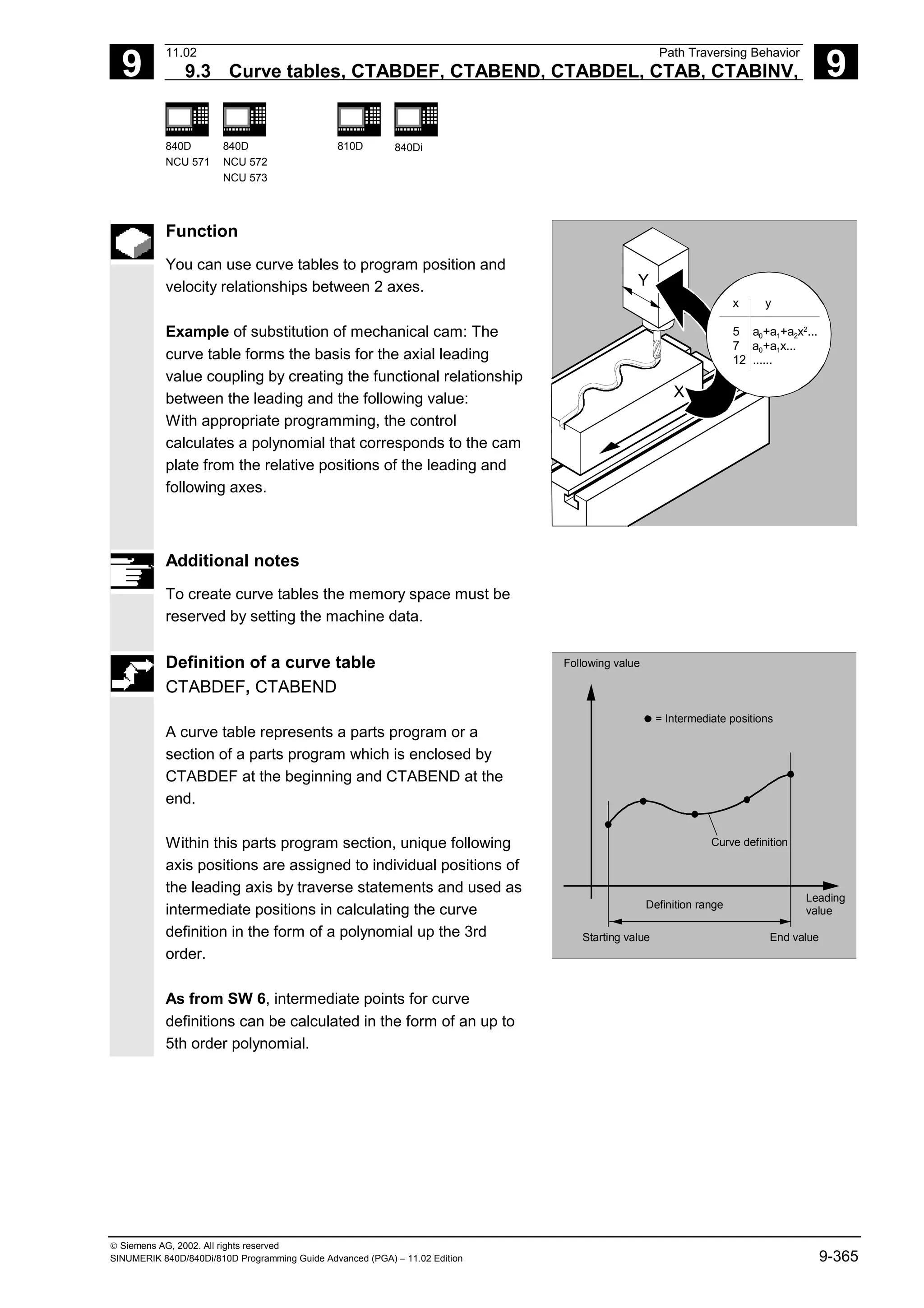
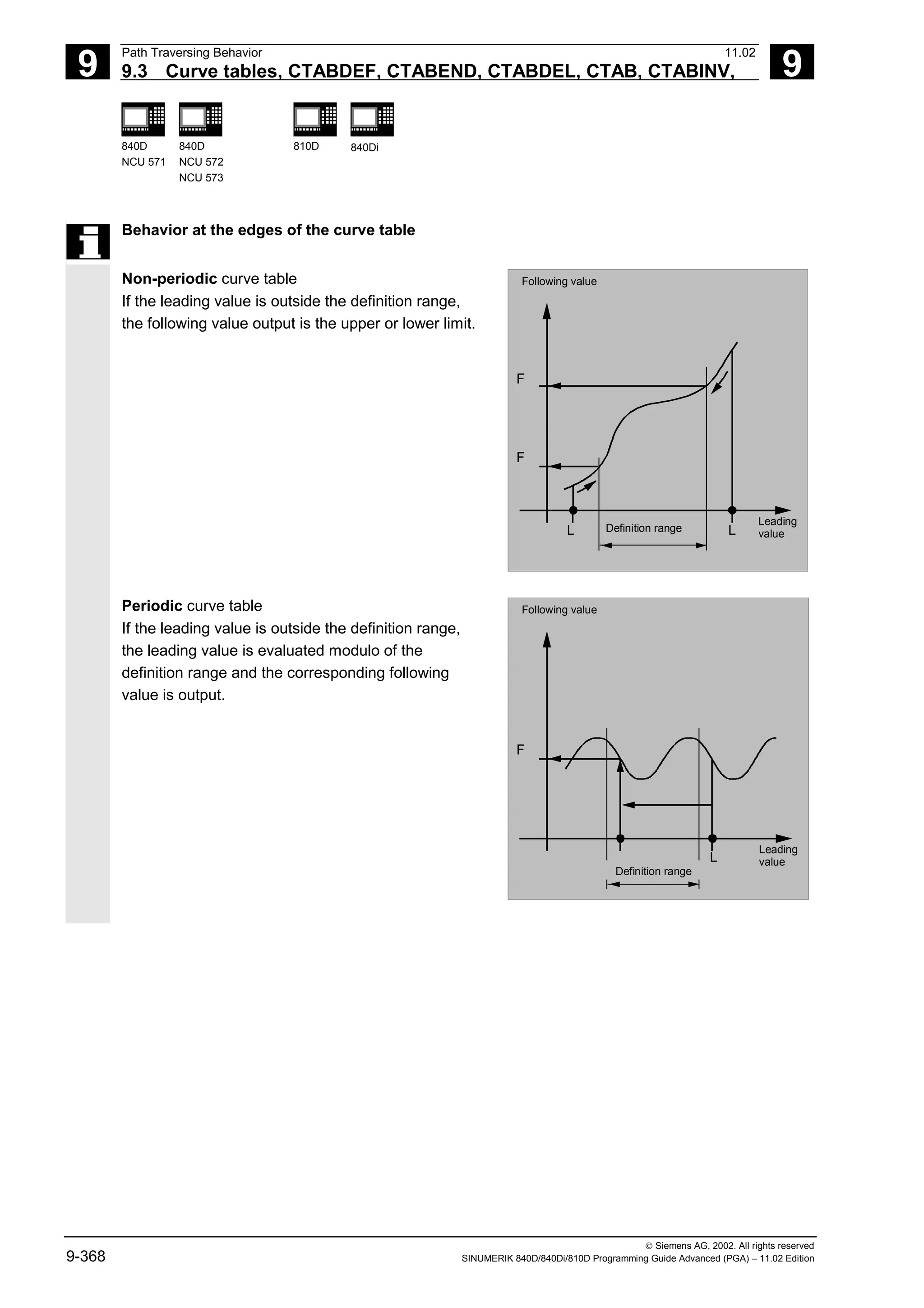
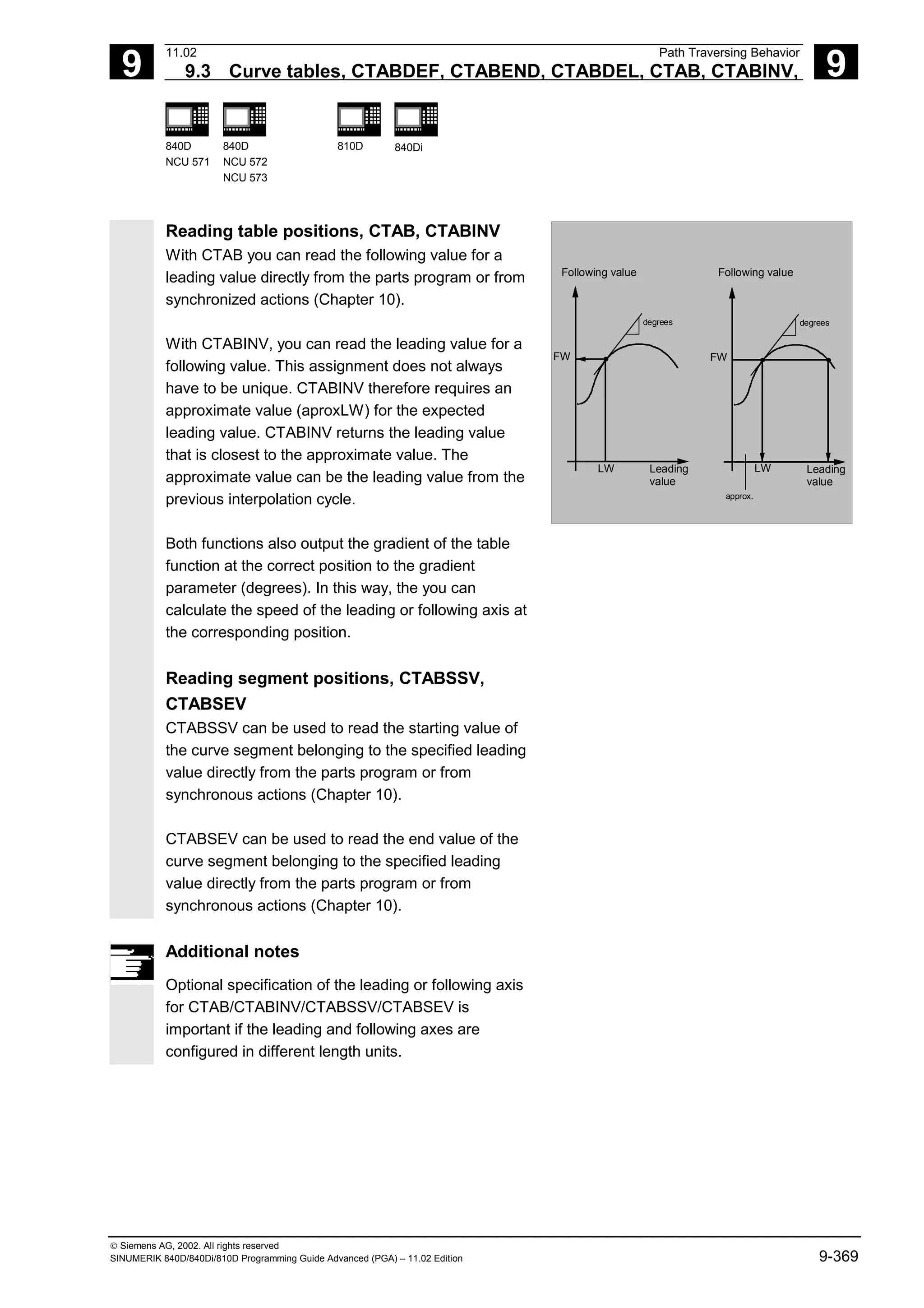
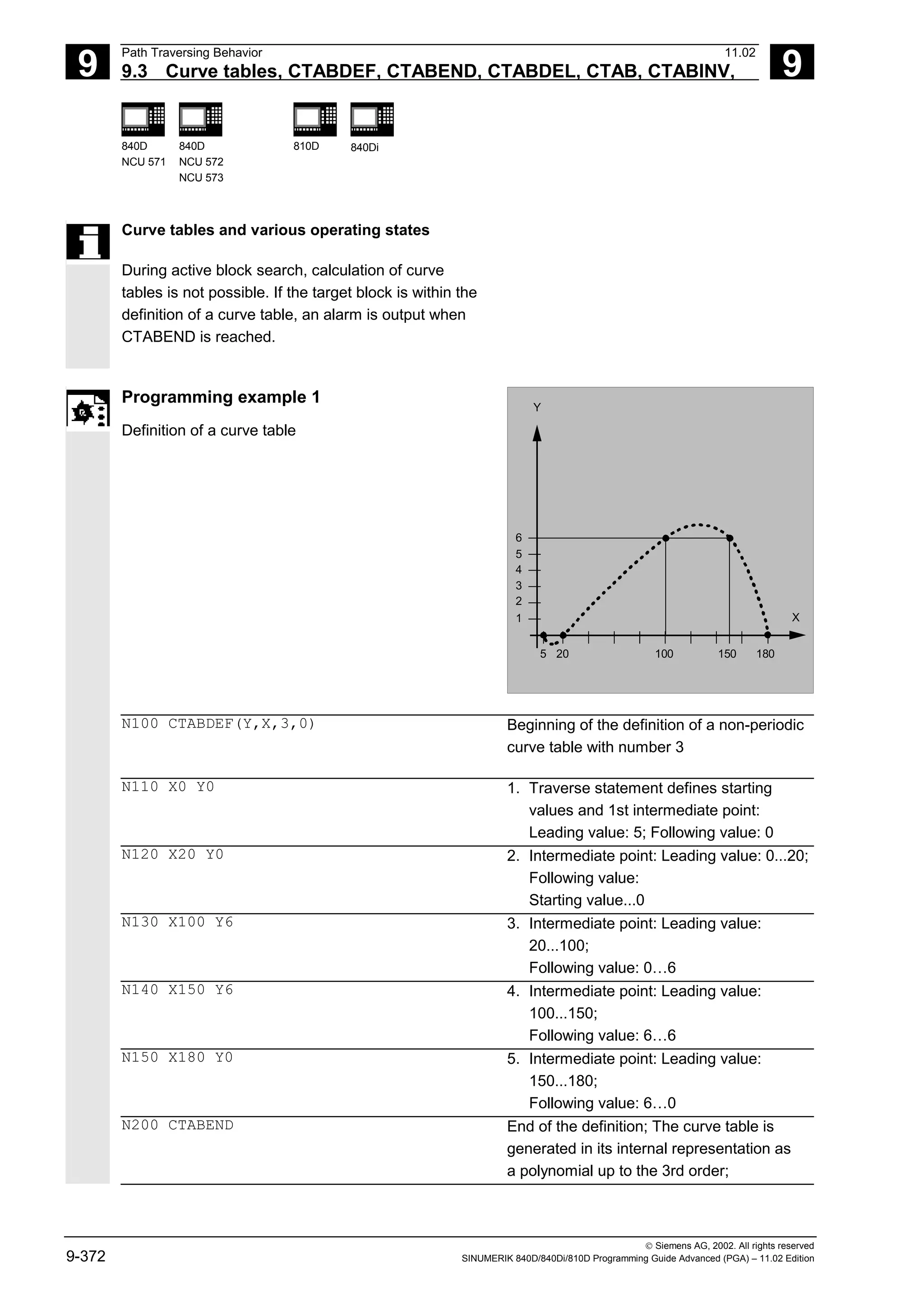
![9
11.02 Path Traversing Behavior
9.3 Curve tables, CTABDEF, CTABEND, CTABDEL, CTAB, CTABINV, 9
840D
NCU 571
840D
NCU 572
NCU 573
810D 840Di
Siemens AG, 2002. All rights reserved
SINUMERIK 840D/840Di/810D Programming Guide Advanced (PGA) – 11.02 Edition 9-373
The calculation of the curve definition
depends on the modally selected
interpolation type (circle, linear, spline
interpolation); The parts program state
before the beginning of the definition is
restored.
Programming example 2
Definition of a periodic curve table with number 2,
leading value range 0 to 360, following axis motion
from 0 to 45 and back to 0:
N10 DEF REAL DEPPOS;
N20 DEF REAL GRADIENT;
N30 CTABDEF(Y,X,2,1) Beginning of definition
N40 G1 X=0 Y=0
N50 POLY
N60 PO[X]=(45.0)
N70 PO[X]=(90.0) PO[Y]=(45.0,135.0,-
90)
N80 PO[X]=(270.0)
N90 PO[X]=(315.0) PO[Y]=(0.0,-
135.0,90)
N100 PO[X]=(360.0)
N110 CTABEND End of definition
Test of the curve by coupling Y to X:
N120 G1 F1000 X0
N130 LEADON(Y,X,2)
N140 X360
N150 X0
N160 LEADOF(Y,X)
Read the table function for leading value 75.0:
N170 DEPPOS=CTAB(75.0,2,GRADIENT)
Positioning of the leading and the following axis:
N180 G0 X75 Y=DEPPOS](https://image.slidesharecdn.com/fadaladvancedprogrammingmanual-220505063253/75/Fadal-Advanced-Programming-Manual-pdf-373-2048.jpg)
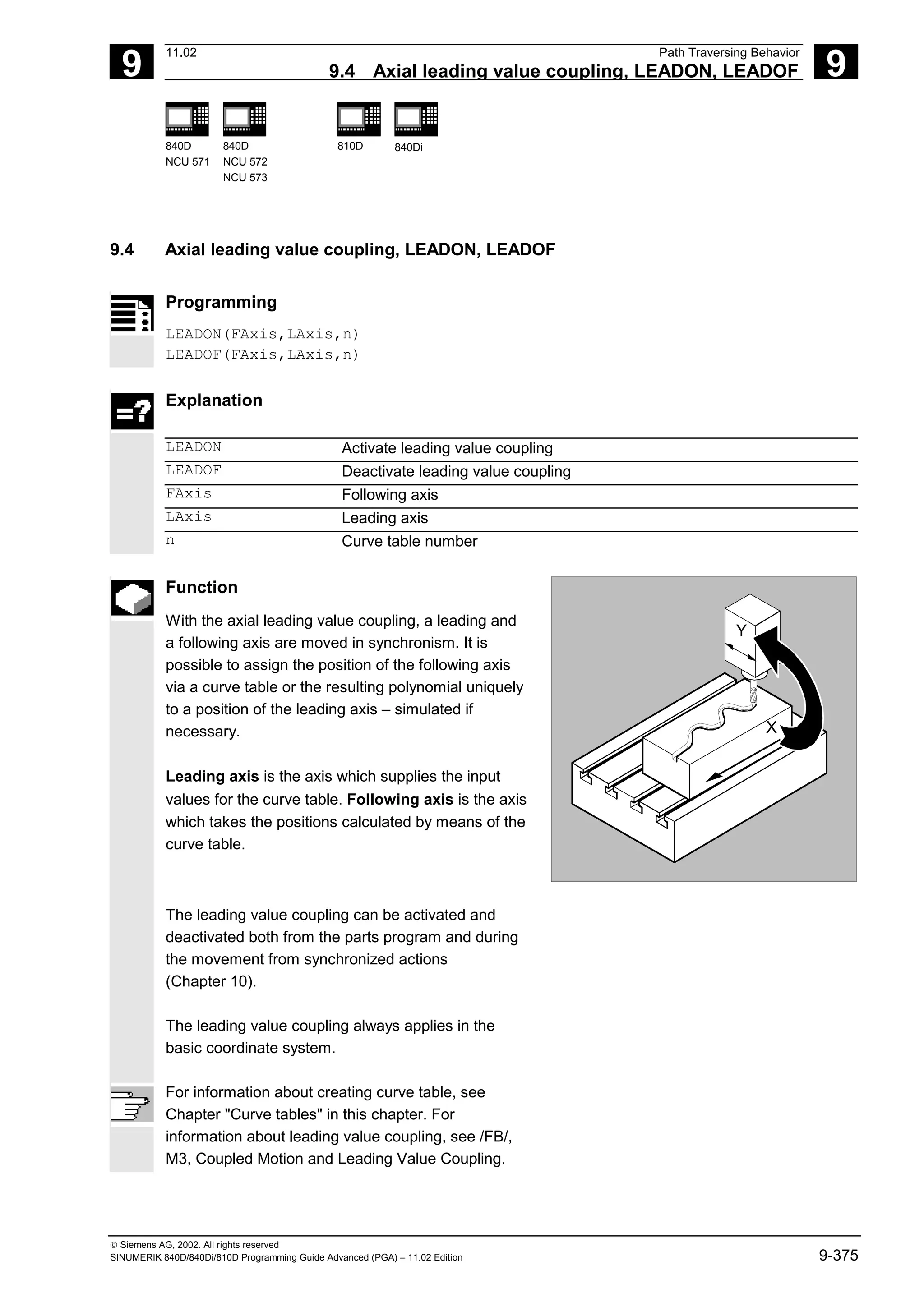
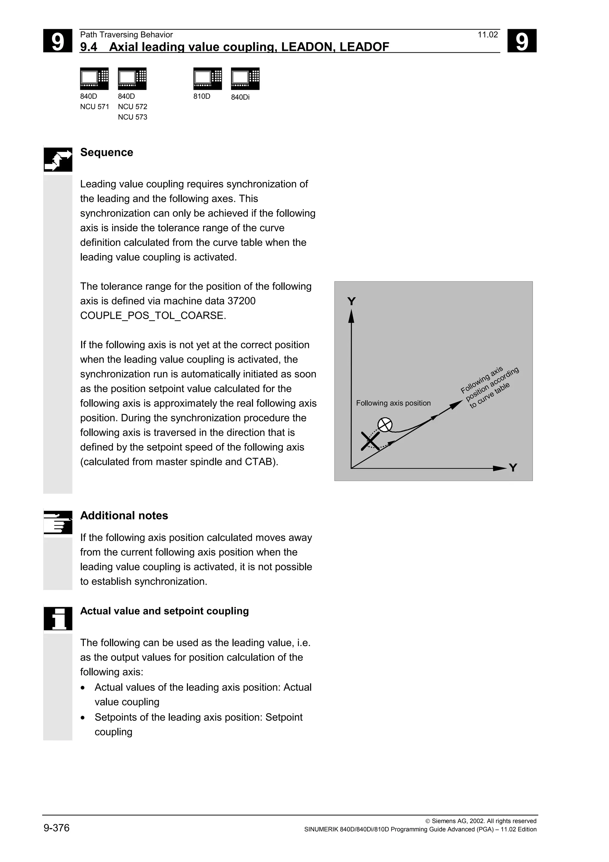
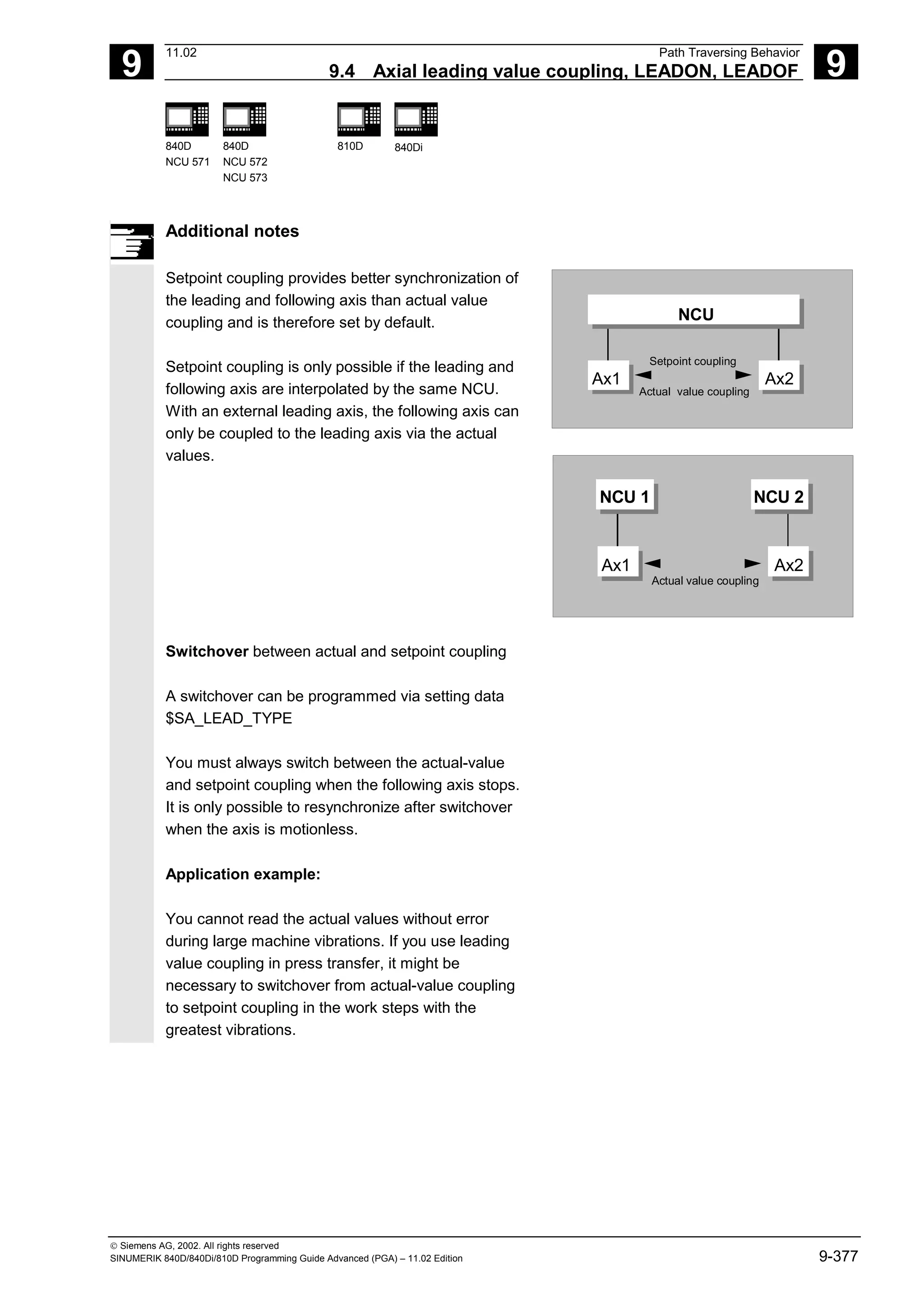
![9
Path Traversing Behavior 11.02
9.4 Axial leading value coupling, LEADON, LEADOF 9
840D
NCU 571
840D
NCU 572
NCU 573
810D 840Di
Siemens AG, 2002. All rights reserved
9-378 SINUMERIK 840D/840Di/810D Programming Guide Advanced (PGA) – 11.02 Edition
Leading value simulation with setpoint simulation
Via machine data, you can disconnect the
interpolator for the leading axis from the servo. In
this way you can generate setpoints for setpoint
coupling without actually moving the leading axis.
Leading values generated from a setpoint link can
be read from the following variables so that they can
be used, for example, in synchronized actions:
- $AA_LEAD_P Leading value position
- $AA_LEAD_V Leading value velocity
Additional notes
As an option, leading values can be generated with
other self-programmed methods. The leading values
generated in this way are written into the variables
- $AA_LEAD_SP Leading value position
- $AA_LEAD_SV Leading value velocity
and read from them. Before you use these variables,
setting data $SA_LEAD_TYPE = 2 must be set.
Status of coupling
You can query the status of the coupling in the NC
program with the following system variable:
$AA_COUP_ACT[axis]
0 No coupling active
16 Leading value coupling active
Deactivate leading value coupling, LEADOF
When you deactivate the leading value coupling, the
following axis becomes a normal command axis
again!
Axial leading value coupling and different
operating states
Depending on the setting in the machine data, the
leading value couplings are deactivated with RESET.](https://image.slidesharecdn.com/fadaladvancedprogrammingmanual-220505063253/75/Fadal-Advanced-Programming-Manual-pdf-378-2048.jpg)
![9
11.02 Path Traversing Behavior
9.4 Axial leading value coupling, LEADON, LEADOF 9
840D
NCU 571
840D
NCU 572
NCU 573
810D 840Di
Siemens AG, 2002. All rights reserved
SINUMERIK 840D/840Di/810D Programming Guide Advanced (PGA) – 11.02 Edition 9-379
Programming example
In a pressing plant, an ordinary mechanical coupling
between a leading axis (stanchion shaft) and axis of
a transfer system comprising transfer axes and
auxiliary axes is to be replaced by an electronic
coupling system.
It demonstrates how a mechanical transfer system is
replaced by an electronic transfer system. The
coupling and decoupling events are implemented as
static synchronized actions.
From the leading axis LW (stanchion shaft), transfer
axes and auxiliary axes are controlled as following
axes that are defined via curve tables.
Following axes X Feed or longitudinal axis
YL Closing or lateral axis
ZL Stroke axis
U Roller feed, auxiliary axis
V Guiding head, auxiliary axis
W Greasing, auxiliary axis
Status management
Switching and coupling events are managed via real-
time variables:
$AC_MARKER[i]=n
with:
i Marker number
n Status value
Actions
The actions that occur include, for example, the following synchronized actions:
• Activate coupling, LEADON(following axis, leading axis, curve table number)
• Deactivate coupling, LEADOF(following axis, leading axis)
• Set actual value, PRESETON(axis, value)
• Set marker, $AC_MARKER[i]=value
• Coupling type: real/virtual leading value
• Approaching axis positions, POS[axis]=value
Conditions
Fast digital inputs, real-time variables $AC_MARKER and position comparisons are linked using
the Boolean operator AND for evaluation as conditions.
Note
In the following example, line change, indentation and bold type are used for the sole purpose of
improving readability of the program. To the controller, everything that follows a line number
constitutes a single line.](https://image.slidesharecdn.com/fadaladvancedprogrammingmanual-220505063253/75/Fadal-Advanced-Programming-Manual-pdf-379-2048.jpg)
![9
Path Traversing Behavior 11.02
9.4 Axial leading value coupling, LEADON, LEADOF 9
840D
NCU 571
840D
NCU 572
NCU 573
810D 840Di
Siemens AG, 2002. All rights reserved
9-380 SINUMERIK 840D/840Di/810D Programming Guide Advanced (PGA) – 11.02 Edition
Comment
; Defines all static synchronized actions.
; **** Reset marker
N2 $AC_MARKER[0]=0 $AC_MARKER[1]=0
$AC_MARKER[2]=0 $AC_MARKER[3]=0
$AC_MARKER[4]=0 $AC_MARKER[5]=0
$AC_MARKER[6]=0 $AC_MARKER[7]=0
; **** E1 0=>1 Coupling transfer ON
N10 IDS=1 EVERY ($A_IN[1]==1) AND
($A_IN[16]==1) AND ($AC_MARKER[0]==0)
DO LEADON(X,LW,1) LEADON(YL,LW,2)
LEADON(ZL,LW,3) $AC_MARKER[0]=1
;**** E1 0=>1 Coupling roller feed ON
N20 IDS=11 EVERY ($A_IN[1]==1) AND
($A_IN[5]==0) AND ($AC_MARKER[5]==0)
DO LEADON(U,LW,4) PRESETON(U,0)
$AC_MARKER[5]=1
; **** E1 0->1 Coupling guide head ON
N21 IDS=12 EVERY ($A_IN[1]==1) AND
($A_IN[5]==0) AND ($AC_MARKER[6]==0)
DO LEADON(V,LW,4) PRESETON(V,0)
$AC_MARKER[6]=1
; **** E1 0->1 Coupling greasing ON
N22 IDS=13 EVERY ($A_IN[1]==1) AND
($A_IN[5]==0) AND ($AC_MARKER[7]==0)
DO LEADON(W,LW,4) PRESETON(W,0)
$AC_MARKER[7]=1
; **** E2 0=>1 Coupling OFF
N30 IDS=3 EVERY ($A_IN[2]==1)
DO LEADOF(X,LW) LEADOF(YL,LW)
LEADOF(ZL,LW) LEADOF(U,LW)
LEADOF(V,LW) LEADOF(W,LW) $AC_MARKER[0]=0
$AC_MARKER[1]=0 $AC_MARKER[3]=0
$AC_MARKER[4]=0 $AC_MARKER[5]=0
$AC_MARKER[6]=0 $AC_MARKER[7]=0
....
N110 G04 F01
N120 M30](https://image.slidesharecdn.com/fadaladvancedprogrammingmanual-220505063253/75/Fadal-Advanced-Programming-Manual-pdf-380-2048.jpg)
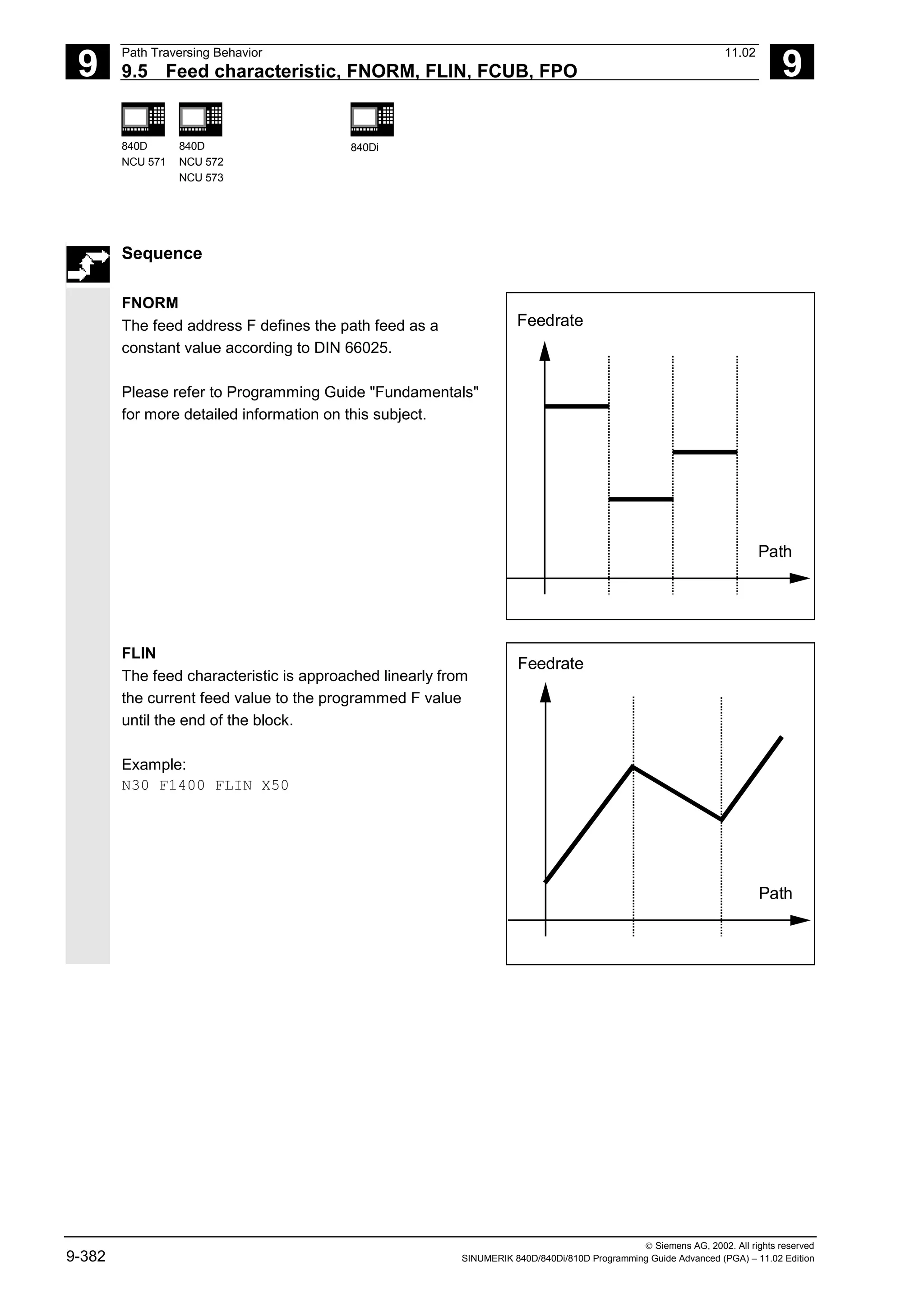
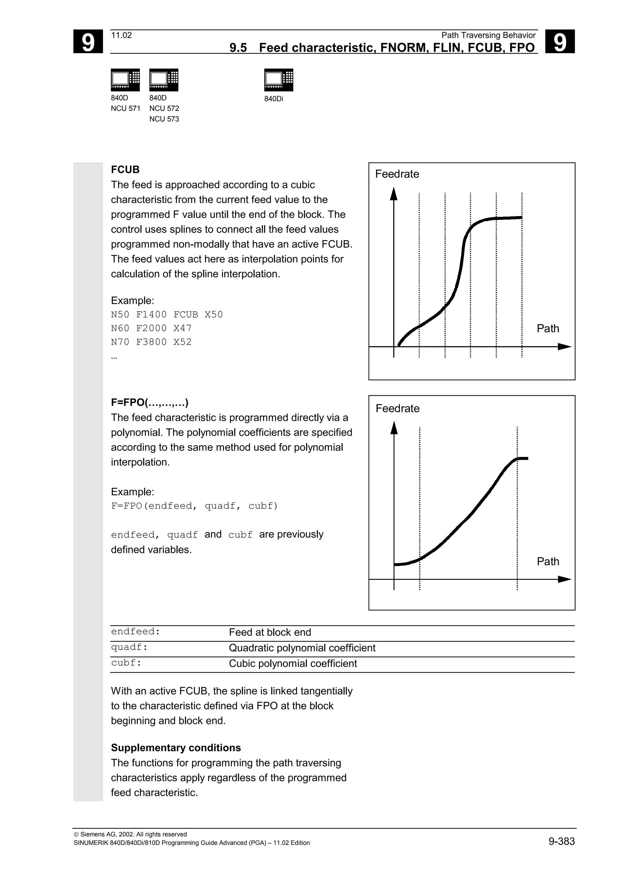
![9
11.02 Path Traversing Behavior
9.6 Program run with preprocessing memory, STARTFIFO, STOPFIFO, 9
840D
NCU 571
840D
NCU 572
NCU 573
810D 840Di
Siemens AG, 2002. All rights reserved
SINUMERIK 840D/840Di/810D Programming Guide Advanced (PGA) – 11.02 Edition 9-387
Restrictions
The preprocessing memory is not filled or the filling
process interrupted if the processing section
contains commands that require unbuffered
operation (reference point approach, measuring
functions, ...).
Stop preprocessing
When STOPRE is programmed, the following block is
not processed until all previously prepared and stored
blocks have been fully executed. The previous block is
halted with exact stop (as for G9).
Example:
N10 …
N30 MEAW=1 G1 F1000 X100 Y100 Z50
N40 STOPRE
The control system initiates an internal preprocessing
stop while status data of the machine ($A...) are
accessed.
Example:
R10 = $AA_IM[X] ;Read actual value of X axis
Note
When a tool offset or spline interpolations are active,
you should not program the STOPRE command as
this will lead to interruption in contiguous block
sequences.](https://image.slidesharecdn.com/fadaladvancedprogrammingmanual-220505063253/75/Fadal-Advanced-Programming-Manual-pdf-387-2048.jpg)
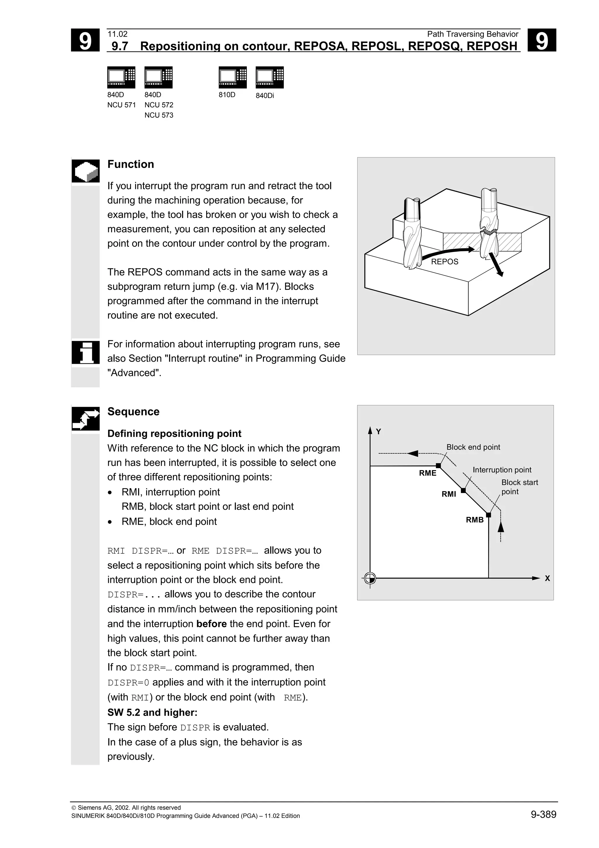
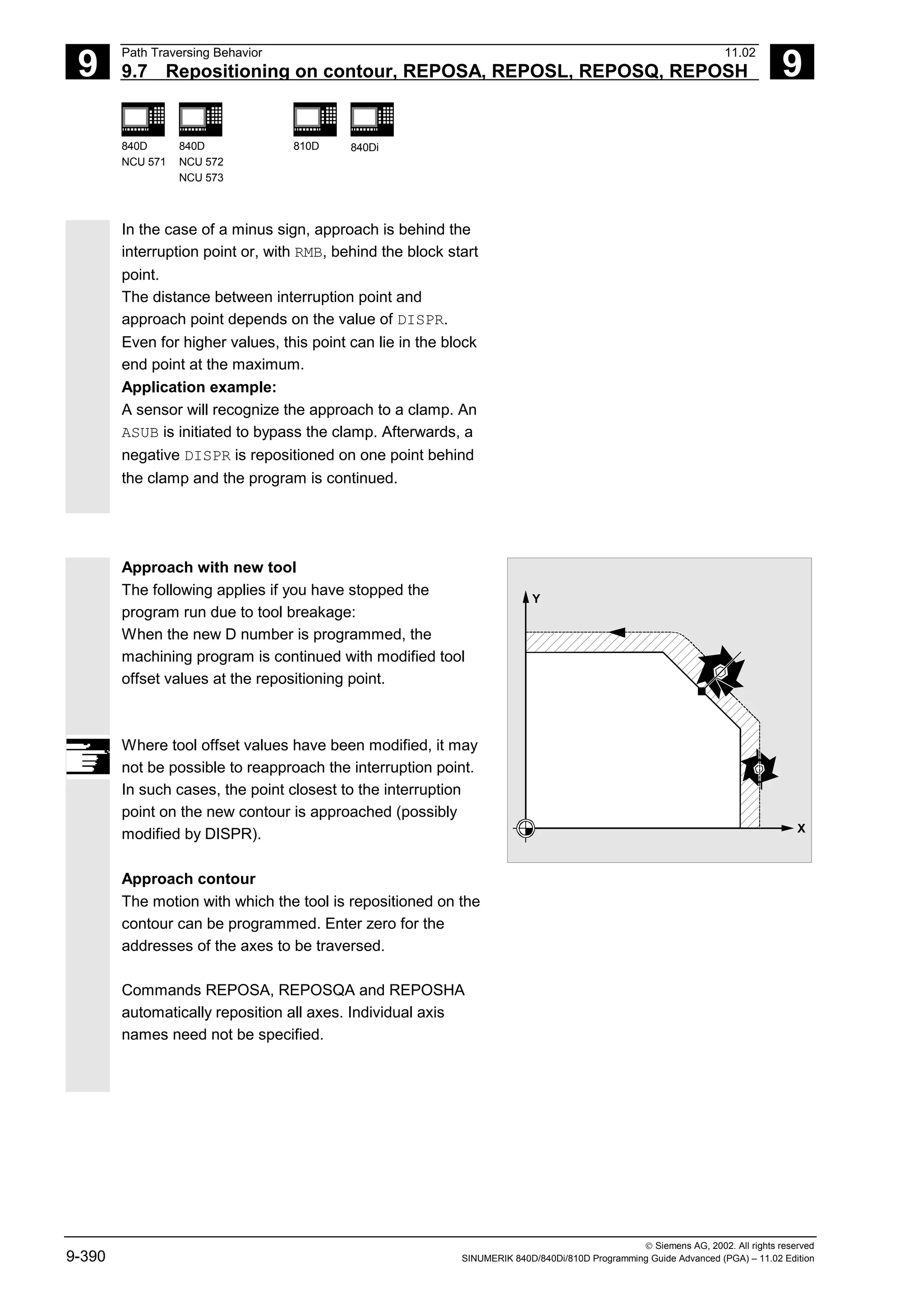
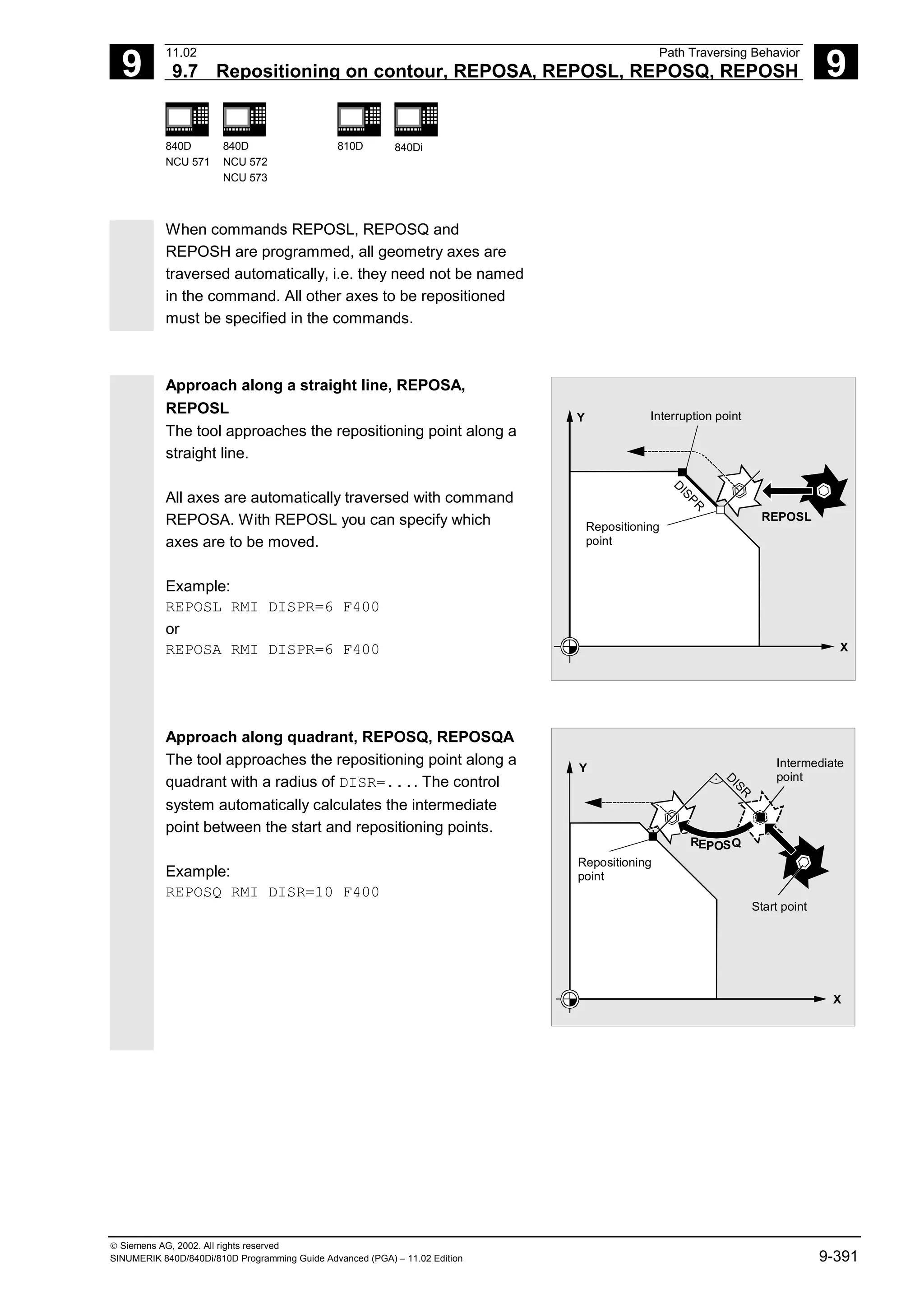
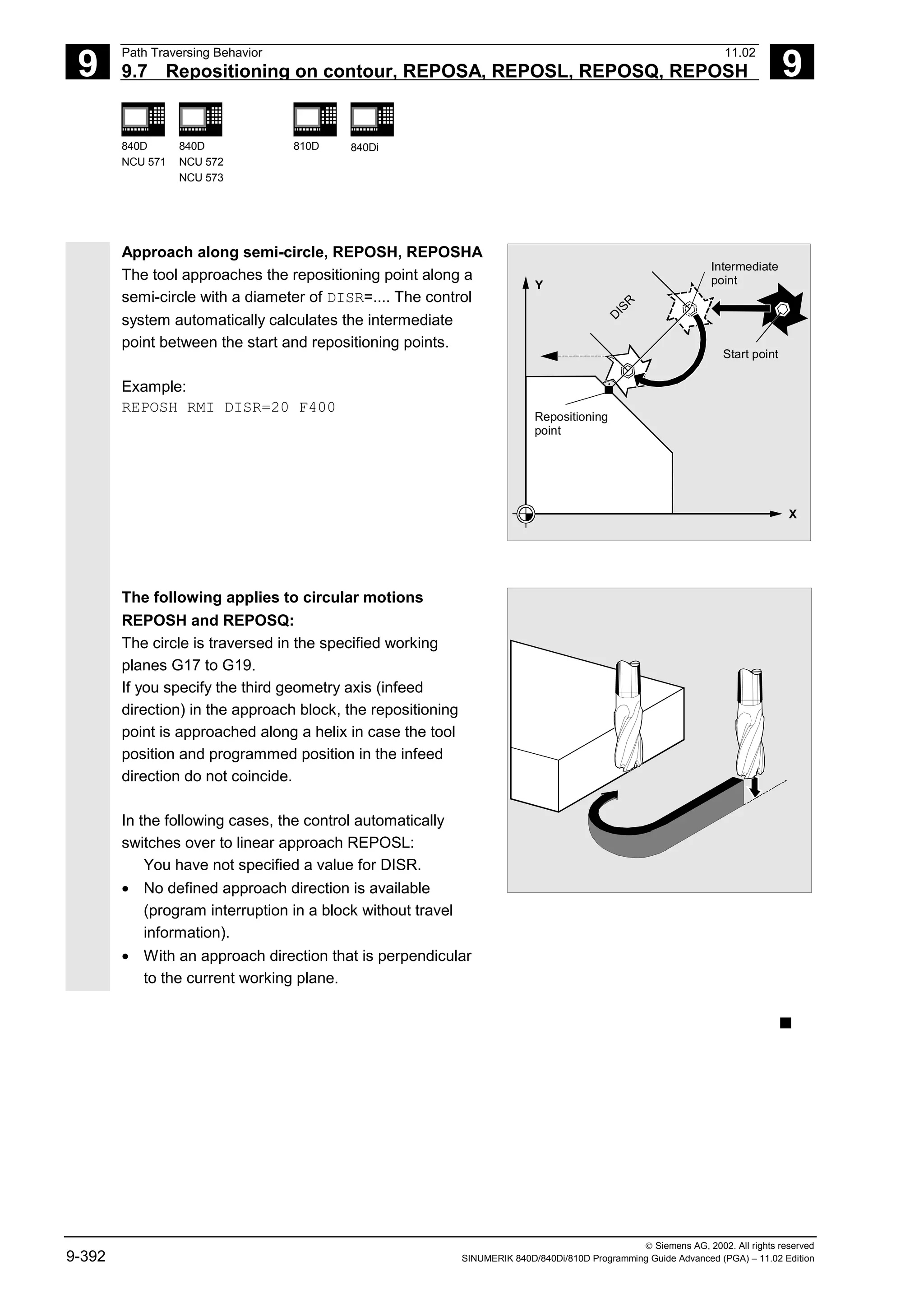
![10
11.02 Motion-Synchronous Action
10
Siemens AG, 2002. All rights reserved
SINUMERIK 840D/840Di/810D Programming Guide Advanced (PGA) – 11.02 Edition 10-393
Motion-Synchronous Action
10.1 Structure, basic information ........................................................................................ 10-395
10.1.1 Programming and command elements................................................................ 10-397
10.1.2 Validity range: Identification number ID ............................................................... 10-398
10.1.3 Vocabulary word .................................................................................................. 10-399
10.1.4 Actions ................................................................................................................. 10-402
10.1.5 Overview of synchronized actions........................................................................ 10-404
10.2 Basic modules for conditions and actions................................................................... 10-406
10.3 Special real-time variables for synchronized actions .................................................. 10-409
10.3.1 Flags/counters $AC_MARKER[n]........................................................................ 10-409
10.3.2 Timer variable $AC_TIMER[n], SW 4 and higher................................................ 10-409
10.3.3 Synchronized action parameters $AC_PARAM[n]............................................... 10-410
10.3.4 Access to R parameters $Rxx ............................................................................. 10-411
10.3.5 Machine and setting data read/write (SW 4 and higher)...................................... 10-412
10.3.6 FIFO variable $AC_FIFO1[n] … $AC_FIFO10[n] (SW 4 and higher).................. 10-413
10.4 Actions within synchronized actions............................................................................ 10-415
10.4.1 Auxiliary functions output ..................................................................................... 10-415
10.4.2 Set read-in disable RDISABLE ............................................................................ 10-416
10.4.3 Cancel preprocessing stop STOPREOF ............................................................. 10-417
10.4.4 Deletion of distance-to-go.................................................................................... 10-418
10.4.5 Delete distance-to-go with preparation, DELDTG, DELDTG ("Axis 1 to x") ........ 10-418
10.4.6 Polynomial definition, FCTDEF, block-synchronized ........................................... 10-420
10.4.7 Laser power control ............................................................................................. 10-422
10.4.8 Evaluation function SYNFCT ............................................................................... 10-423
10.4.9 Adaptive control (additive).................................................................................... 10-424
10.4.10 Adaptive control (multiplicative) ........................................................................... 10-425
10.4.11 Clearance control with limited compensation....................................................... 10-426
10.4.12 Online tool offset FTOC ....................................................................................... 10-428
10.4.13 Positioning movements........................................................................................ 10-430
10.4.14 Position axis POS ................................................................................................ 10-432
10.4.15 Start/stop axis MOV............................................................................................. 10-432
10.4.16 Axial feed FA........................................................................................................ 10-433
10.4.17 SW limit switch..................................................................................................... 10-434
10.4.18 Axis coordination.................................................................................................. 10-434
10.4.19 Set actual value.................................................................................................... 10-436
10.4.20 Spindle motions ................................................................................................... 10-437
10.4.21 Coupled-axis motion TRAILON, TRAILOF .......................................................... 10-438
10.4.22 Leading value coupling LEADON, LEADOF ........................................................ 10-439
10.4.23 Measurement....................................................................................................... 10-441
10.4.24 Set/clear wait marks: SETM, CLEARM (SW 5.2 and higher).............................. 10-441](https://image.slidesharecdn.com/fadaladvancedprogrammingmanual-220505063253/75/Fadal-Advanced-Programming-Manual-pdf-393-2048.jpg)
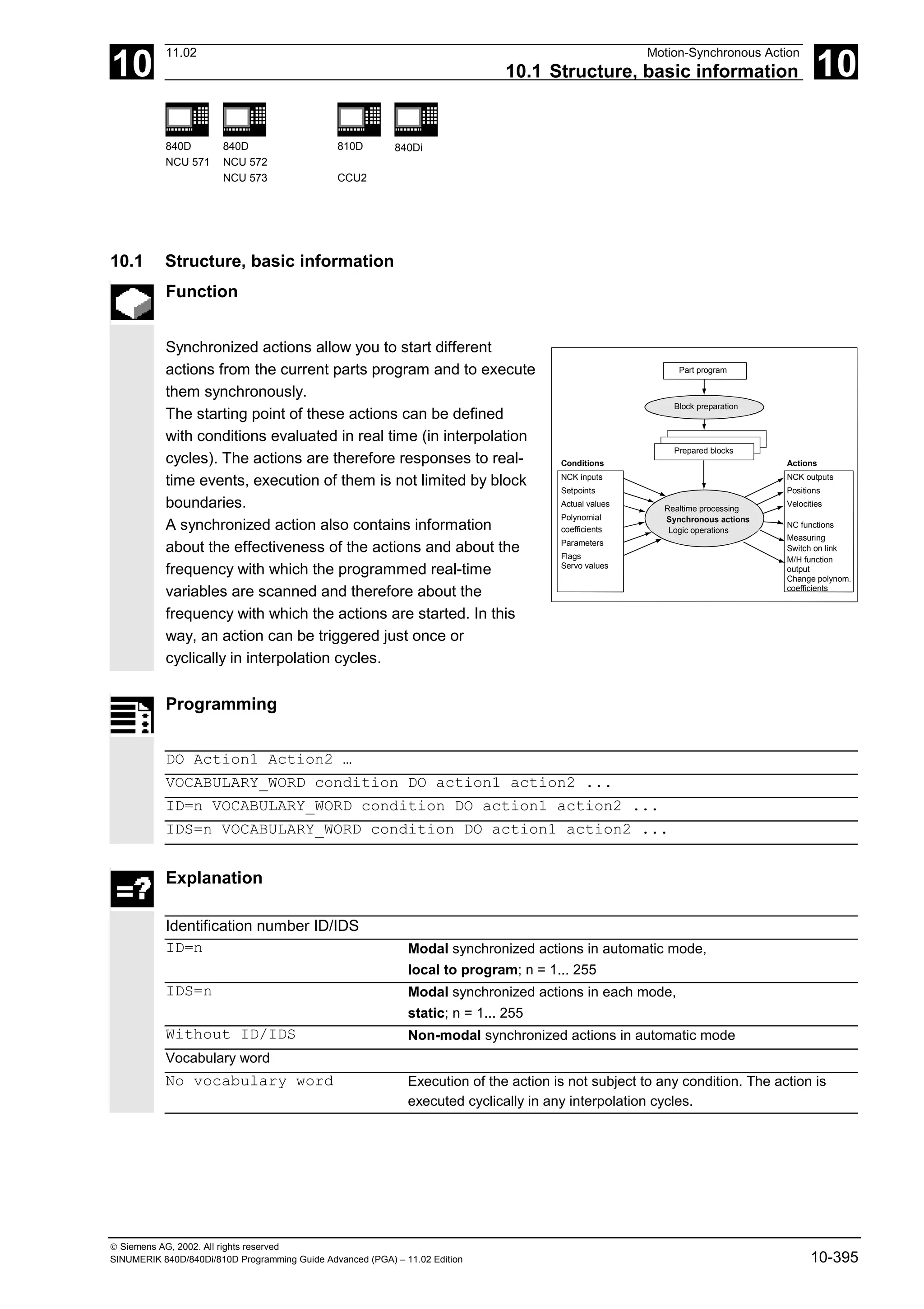
![10
Motion-Synchronous Action 11.02
10.1 Structure, basic information 10
840 D
NCU 571
840 D
NCU 572
NCU 573
810 D 840Di
Siemens AG, 2002. All rights reserved
10-396 SINUMERIK 840D/840Di/810D Programming Guide Advanced (PGA) – 11.02 Edition
WHEN The condition is tested until it is fulfilled once, the associated action
is executed once.
WHENEVER The condition is tested cyclically. The associated action is executed
cyclically while the condition is fulfilled.
FROM After the condition has been fulfilled once, the action is executed
cyclically while the synchronized action is active.
EVERY The action is initiated once when the condition is fulfilled and is
executed again when the condition changes from the FALSE state to
the TRUE state. The condition is tested cyclically. Every time the
condition is fulfilled, the associated action is executed.
Condition Gating logic for real-time variables, the conditions are checked in the
interpolation cycle.
In SW 5 and higher, the G codes can be programmed in synchronized
actions for condition evaluation.
DO Triggers the action if the condition is fulfilled.
Action Action started if the condition is fulfilled, e.g. assign variable,
activate axis coupling, set NCK outputs, output M and H functions, ...
In SW 5 and higher, the G codes can be programmed in synchronized
actions for actions/technology cycles.
Coordination of synchronized actions/technology cycles
CANCEL[n] Cancel synchronized action
LOCK[n] Inhibit technology cycle
UNLOCK[n] Enable technology cycle
RESET Reset technology cycle
Programming example
WHEN $AA_IW[Q1]>5 DO M172 H510 ;If the actual value of axis Q1 exceeds 5 mm, auxiliary
functions M172 and H510 are output to the PLC interface.
If real-time variables occur in a parts program
(e.g. actual value, position of a digital input or output
etc.), preprocessing is stopped until the previous block
has been executed and the values of the real-time
variables obtained.
The real-time variables used are evaluated in
interpolation cycles.
Advantages with synchronized actions:
Preprocessing is not stopped.](https://image.slidesharecdn.com/fadaladvancedprogrammingmanual-220505063253/75/Fadal-Advanced-Programming-Manual-pdf-396-2048.jpg)
![10
11.02 Motion-Synchronous Action
10.1 Structure, basic information 10
840D
NCU 571
840D
NCU 572
NCU 573
810D
CCU2
840Di
Siemens AG, 2002. All rights reserved
SINUMERIK 840D/840Di/810D Programming Guide Advanced (PGA) – 11.02 Edition 10-397
Possible applications:
• Optimization of runtime-critical applications
(e.g. tool changing)
• Fast response to an external event
• Programming AC controls
• Setting up safety functions
• ....
10.1.1 Programming and command elements
Function
A synchronized action is programmed on its own in a
separate block and triggers a machine function in
the next executable block (e.g. traversing movement
with G0, G1, G2, G3; block with auxiliary function
output).
Synchronized actions consist of up to five command
elements each with a different task:
ID n um b er:
S c op e of va lid ity
V o ca bu la ry w ord :
S can fre qu en cy
opt.
G
code
for
condition
C o nd ition D O
opt.
G
code
for
action/techno.
c.
A ctio n
Technology
cycle
Example:
ID=1 WHENEVER $A_IN[1]==1 DO $A_OUT[1]=1
Synchronized action no. 1: whenever input 1 is set then set output 1](https://image.slidesharecdn.com/fadaladvancedprogrammingmanual-220505063253/75/Fadal-Advanced-Programming-Manual-pdf-397-2048.jpg)
![10
Motion-Synchronous Action 11.02
10.1 Structure, basic information 10
840 D
NCU 571
840 D
NCU 572
NCU 573
810 D 840Di
Siemens AG, 2002. All rights reserved
10-398 SINUMERIK 840D/840Di/810D Programming Guide Advanced (PGA) – 11.02 Edition
10.1.2 Validity range: Identification number ID
Function
The scope of validity of a synchronized action is
defined by the identification number (modal ID):
• No modal ID
The synchronized action is active in automatic mode
only. It applies only to the next executable block
(block with motion instructions or other machine
action), is non-modal.
Example:
WHEN $A_IN[3]==TRUE DO $A_OUTA[4]=10
G1 X20 ;Executable block
• ID=n; n=1...255
The synchronized action applies modally in the
following blocks and is deactivated by CANCEL(n) or
by programming a new synchronized action with the
same ID.
The synchronized actions that apply in the M30
block are also still active (if necessary deactivate
with the CANCEL command).
ID synchronized actions only apply in automatic
mode.
Example:
ID=2 EVERY $A_IN[1]==1 DO POS[X]=0
• IDS=n; n=1...255
These static synchronized actions apply modally in
all operating modes.
They can be defined not only for starting from a
parts program but also directly after power-on from
an asynchronous subprogram (ASUB) started by the
PLC. In this way, actions can be activated that are
executed regardless of the mode selected in the NC.
Example:
IDS=1 EVERY $A_IN[1]==1 DO POS[X]=100](https://image.slidesharecdn.com/fadaladvancedprogrammingmanual-220505063253/75/Fadal-Advanced-Programming-Manual-pdf-398-2048.jpg)
![10
11.02 Motion-Synchronous Action
10.1 Structure, basic information 10
840D
NCU 571
840D
NCU 572
NCU 573
810D
CCU2
840Di
Siemens AG, 2002. All rights reserved
SINUMERIK 840D/840Di/810D Programming Guide Advanced (PGA) – 11.02 Edition 10-399
Application:
• AC loops in JOG mode
• Logic operations for Safety Integrated
• Monitoring functions, responses to machine states in
all modes
Sequence of execution
Synchronized actions that apply modally or statically
are executed in the order of their ID(S) numbers (in
the interpolation cycle).
Non-modal synchronized actions (without ID
number) are executed in the programmed sequence
after execution of the modal synchronized actions.
10.1.3 Vocabulary word
Function
The vocabulary word determines how many times the
following condition is to be scanned and the associated
action executed.
• No vocabulary word:
If no vocabulary word is programmed, the condition is
considered to be always fulfilled. The synchronous
commands are executed cyclically.
Example:
DO $A_OUTA[1]=$AA_IN[X]
;Output of actual value on analog
output
• WHEN
The condition is scanned in each interpolation cycle
until it is fulfilled once, whereupon the action is
executed once.
• WHENEVER
The condition is scanned in each interpolation cycle.
The action is executed in each interpolation cycle while
the condition is fulfilled.](https://image.slidesharecdn.com/fadaladvancedprogrammingmanual-220505063253/75/Fadal-Advanced-Programming-Manual-pdf-399-2048.jpg)
![10
Motion-Synchronous Action 11.02
10.1 Structure, basic information 10
840 D
NCU 571
840 D
NCU 572
NCU 573
810 D 840Di
Siemens AG, 2002. All rights reserved
10-400 SINUMERIK 840D/840Di/810D Programming Guide Advanced (PGA) – 11.02 Edition
• FROM
The condition is tested in each interpolation cycle
until it is fulfilled once. The action is then executed
while the synchronous action is active, i.e. even if
the condition is no longer fulfilled.
• EVERY
The condition is scanned in each interpolation cycle.
The action is executed once whenever the condition
is fulfilled.
Pulse edge control:
The action is initiated again when the condition
changes from FALSE to TRUE.
Condition
Defines whether an action is to be executed by comparing
two real-time variables or one real-time variable with an
expression calculated during preprocessing.
SW 4 and higher:
Results of comparisons can also be gated by Boolean
operators in the condition ().
The condition is tested in interpolation cycles. If it is
fulfilled, the associated action is executed.
SW 5 and higher:
Conditions can be specified with a G code. This means
that it is possible to have defined settings for condition
evaluation and the action/technology cycle irrespective
of the currently active parts program state. It is
necessary to decouple synchronized actions from the
programming environment because synchronized
actions are to execute their actions in the defined initial
state at any time when the trigger conditions are
fulfilled.
Application cases:
Defining the measurement systems for condition
assessment and action via G codes G70, G71, G700,
G710.
Example:
ID=1 EVERY $AA_IM[B]>75 DO
POS[U]=IC(10) FA[U]=900;
When the actual value of axis B
overshoots the value 75 in
machine coordinates, the U axis
should move forwards by 10 with
an axial feed.](https://image.slidesharecdn.com/fadaladvancedprogrammingmanual-220505063253/75/Fadal-Advanced-Programming-Manual-pdf-400-2048.jpg)
![10
11.02 Motion-Synchronous Action
10.1 Structure, basic information 10
840D
NCU 571
840D
NCU 572
NCU 573
810D
CCU2
840Di
Siemens AG, 2002. All rights reserved
SINUMERIK 840D/840Di/810D Programming Guide Advanced (PGA) – 11.02 Edition 10-401
In SW 5 only these G codes are allowed.
A specified G code for the condition applies for
assessment of the condition as well as for the
action if there is no separate G code specified for the
action.
Only one G code of the G code group may be
programmed for each condition part.
Programming example
WHENEVER $AA_IM[X] > 10.5*SIN(45) DO … Comparison with an expression
calculated during preprocessing
WHENEVER $AA_IM[X] > $AA_IM[X1] DO … Comparison with other real-time
variable
WHENEVER ($A_IN[1]==1) OR ($A_IN[3]==0) DO
...
Two logic-gated comparisons
Possible conditions:
• Comparison of real-time variables
(analog/digital inputs/outputs, etc.)
• Boolean gating of comparison results
• Computation of real-time expressions
• Time/distance from beginning of block
• Distance from block end
• Measured values, measured results
• Servo values
• Velocities, axis status](https://image.slidesharecdn.com/fadaladvancedprogrammingmanual-220505063253/75/Fadal-Advanced-Programming-Manual-pdf-401-2048.jpg)
![10
11.02 Motion-Synchronous Action
10.1 Structure, basic information 10
840D
NCU 571
840D
NCU 572
NCU 573
810D
CCU2
840Di
Siemens AG, 2002. All rights reserved
SINUMERIK 840D/840Di/810D Programming Guide Advanced (PGA) – 11.02 Edition 10-403
• Activate or deactivate coupled-axis
motion/leading value coupling
• Measurement
• Set up additional safety functions
• Output of digital and analog signals
• ...
Programming example
Synchronized action with two actions
WHEN $AA_IM[Y] >= 35.7 DO M135 $AC_PARAM=50
If the condition is fulfilled, M135 is output to the PLC and the override is set to 50%.
As the action, you can also specify a program
(single-axis program, technology cycle). This must
only comprise those actions that can also be
programmed individually in synchronized actions.
The individual actions of such a program are
executed sequentially in interpolation cycles.
Note
Actions can be executed whatever mode is selected.
The following actions are only active in automatic mode
when the program is active
• STOPREOF,
• DELDTG.](https://image.slidesharecdn.com/fadaladvancedprogrammingmanual-220505063253/75/Fadal-Advanced-Programming-Manual-pdf-403-2048.jpg)
![10
Motion-Synchronous Action 11.02
10.2 Basic modules for conditions and actions 10
840 D
NCU 571
840 D
NCU 572
NCU 573
810 D 840Di
Siemens AG, 2002. All rights reserved
10-406 SINUMERIK 840D/840Di/810D Programming Guide Advanced (PGA) – 11.02 Edition
10.2 Basic modules for conditions and actions
Real-time variables
Real-time variables are evaluated and written in the
interpolation cycle.
The real-time variables are
• $A… , main run variable,
• $V... , servo variable.
To identify them specially, these variables can be
programmed with $$:
$AA_IM[X] is equivalent to $$AA_IM[X].
Setting and machine data must be identified with $$
when evaluation/assignment takes place in the
interpolation cycle.
A list of variables is given in the Appendix.
Calculations in real time
Calculations in real time are restricted to the data types
INT, REAL and BOOL.
Real-time expressions are calculations that can be
executed in interpolation cycles that can be used in
the condition and the action for assignment to NC
addresses and variables.
• Comparisons
In conditions, variables or partial expressions of
the same data type can be compared. The result
is always of data type BOOL.
All the usual comparison operators are
permissible (==, <>, <, >, <=, >=).
• Boolean operators
Variables, constants and comparisons can be
gated using the usual Boolean operators (NOT,
AND, OR, XOR)](https://image.slidesharecdn.com/fadaladvancedprogrammingmanual-220505063253/75/Fadal-Advanced-Programming-Manual-pdf-406-2048.jpg)
![10
11.02 Motion-Synchronous Action
10.2 Basic modules for conditions and actions 10
840D
NCU 571
840D
NCU 572
NCU 573
810D
CCU2
840Di
Siemens AG, 2002. All rights reserved
SINUMERIK 840D/840Di/810D Programming Guide Advanced (PGA) – 11.02 Edition 10-407
• Bit operators
The bit operators B_NOT, B_AND, B_OR,
B_XOR can be used.
Operands are variables or constants of the
INTEGER type.
• Basic arithmetic operations
Real-time variables of types INTEGER and REAL
can be subjected to the basic arithmetic
operations, with each other or with a constant (+,
–, *, /, DIV, MOD).
• Mathematical functions
Mathematical functions cannot be applied to real-
time variables of data type REAL (SIN, COS,
TAN, ASIN, ACOS, ABS, TRUNC, ROUND, LN,
EXP, ATAN2, ATAN, POT, SQRT, CTAB,
CTABINV).
Example:
DO $AC_PARAM[3] = COS($AC_PARAM[1])](https://image.slidesharecdn.com/fadaladvancedprogrammingmanual-220505063253/75/Fadal-Advanced-Programming-Manual-pdf-407-2048.jpg)
![10
Motion-Synchronous Action 11.02
10.2 Basic modules for conditions and actions 10
840 D
NCU 571
840 D
NCU 572
NCU 573
810 D 840Di
Siemens AG, 2002. All rights reserved
10-408 SINUMERIK 840D/840Di/810D Programming Guide Advanced (PGA) – 11.02 Edition
Notes
Only variables of the same data type can be
gated.
Correct: $R10=$AC_PARAM[1]
Incorrect: $R10=$AC_MARKER[1]
Multiplication and division are performed before
addition and subtraction and bracketing of
expressions is permissible.
The operators DIV and MOD are permissible for
the data type REAL (SW 4 and higher).
Example:
DO $AC_PARAM[3] = $A_INA[1]-$AA_IM[Z1] ;Subtraction of two real-time variables
WHENEVER $AA_IM[x2] < $AA_IM[x1]-1.9 DO $A_OUT[5] = 1
;Subtraction of a constant from real-time variable
DO $AC_PARAM[3] = $INA[1]-4*SIN(45.7 $P_EP[Y])*R4
;Constant expression, calculated during preprocessing
• Indexation
Real-time variables can be indexed with real-time
variables.
Notes
Variables that are not formed in real time must
not be indexed with real-time variables.
Example:
WHEN…DO $AC_PARAM[$AC_MARKER[1]] = 3
Illegal:
$AC_PARAM[1] = $P_EP[$AC_MARKER]
Programming example
Example of real-time expressions
ID=1 WHENEVER ($AA_IM[Y]>30) AND ($AA_IM[Y]<40)
DO $AA_OVR[S1]=80
Selection of a position window
ID=67 DO $A_OUT[1]=$A_IN[2] XOR $AN_MARKER[1] Evaluate 2 Boolean signals
ID=89 DO $A_OUT[4]=$A_IN[1] OR ($AA_IM[Y]>10) Output of the result of a comparison](https://image.slidesharecdn.com/fadaladvancedprogrammingmanual-220505063253/75/Fadal-Advanced-Programming-Manual-pdf-408-2048.jpg)
![10
11.02 Motion-Synchronous Action
10.3 Special real-time variables for synchronized actions 10
840D
NCU 571
840D
NCU 572
NCU 573
810D
CCU2
840Di
Siemens AG, 2002. All rights reserved
SINUMERIK 840D/840Di/810D Programming Guide Advanced (PGA) – 11.02 Edition 10-409
10.3 Special real-time variables for synchronized actions
The real-time variables listed below can be used in
synchronized actions:
10.3.1 Flags/counters $AC_MARKER[n]
Function
Flag variablescan be read and written in
synchronized actions.
Channel-specific flags/counters
$AC_MARKER[n]
Data type: INTEGER
A channel-specific flag variable exists under the
same name once in each channel.
Example:
WHEN ... DO $AC_MARKER[0] = 2
WHEN ... DO $AC_MARKER[0] = 3
WHEN $AC_MARKER == 3 DO $AC_OVR=50
10.3.2 Timer variable $AC_TIMER[n], SW 4 and higher
Function
(not 840D NCU 571, FM-NC)
The system variable $AC_TIMER[n] allows actions
to be started following defined waiting times.
Data type: REAL
Units: s
n: Number of the timer variable
• Set timer
A timer variable is incremented via value
assignment $AC_TIMER[n]=value](https://image.slidesharecdn.com/fadaladvancedprogrammingmanual-220505063253/75/Fadal-Advanced-Programming-Manual-pdf-409-2048.jpg)
![10
Motion-Synchronous Action 11.02
10.3 Special real-time variables for synchronized actions 10
840 D
NCU 572
NCU 573
810 D
CCU2
840Di
Siemens AG, 2002. All rights reserved
10-410 SINUMERIK 840D/840Di/810D Programming Guide Advanced (PGA) – 11.02 Edition
n: Number of the timer variable
value: Starting value (usually 0)
• Halt timer
Incrementation of a timer variable is halted by
assigning a negative value $AC_TIMER[n]=-1
• Read timer
The current time value can be read when the
timer is running or when it has stopped. When
the timer is stopped by assigning the value -1, the
most up-to-date timer value is retained and can
be read.
Example:
Output of an actual value via analog output
500 ms after detection of a digital input
WHEN $A_IN[1] == 1 DO $AC_TIMER[1]=0 ; Reset and start timer
WHEN $AC_TIMER[1]>=0.5 DO $A_OUTA[3]=$AA_IM[X] $AC_TIMER[1]=-1
10.3.3 Synchronized action parameters $AC_PARAM[n]
Function
Data type: REAL
n: Number of parameter 0-n
Synchronized action parameters $AC_PARAM[n]
are used for calculations and as a buffer in the
synchronized actions.
The number of available AC parameter variables per
channel are defined using machine data MD 28254:
MM_NUM_AC_PARAM.
The parameters are available once per channel
under the same name. The $AC_PARAM flags are
stored in the dynamic memory.](https://image.slidesharecdn.com/fadaladvancedprogrammingmanual-220505063253/75/Fadal-Advanced-Programming-Manual-pdf-410-2048.jpg)
![10
11.02 Motion-Synchronous Action
10.3 Special real-time variables for synchronized actions 10
840D
NCU 572
NCU 573
810D
CCU2
840Di
Siemens AG, 2002. All rights reserved
SINUMERIK 840D/840Di/810D Programming Guide Advanced (PGA) – 11.02 Edition 10-411
10.3.4 Access to R parameters $Rxx
Function
Data type: REAL
These static variables are used for calculations in
the parts program etc. They can be addressed in the
interpolation cycle by appending $.
Examples:
WHEN $AA_IM[X]>=40.5 DO $R10=$AA_MM[Y] Write access to the R parameter 10.
WHEN $AA_IM[X]>=6.7 DO $R[$AC_MARKER[1]]=30.6 ;Read access to the R parameter whose
number is given in flag 1
Notes
Application:
The use of R parameters in synchronized actions
permits
• storage of values that you want to retain beyond
the end of program, NC reset, and Power On.
• display of stored value in the R parameter display
• archiving of values determined for synchronized
actions
The R parameters must be used either as "normal"
arithmetic variables Rxx or as real-time variables $Rxx.
If you want the R parameter to be used as a
"normal" arithmetic variable again after it has been
used in a synchronized action, make sure that the
preprocessing stop is programmed explicitly with
STOPRE for synchronization of preprocessing and
the main run:
Example:
WHEN $AA_IM[X]>=40.5 DO $R10=$AA_MM[Y] Use of R10 in synchronized actions
G01 X500 Y70 F1000
STOPRE Preprocessing stop
IF R10>20 Evaluation of the arithmetic variable](https://image.slidesharecdn.com/fadaladvancedprogrammingmanual-220505063253/75/Fadal-Advanced-Programming-Manual-pdf-411-2048.jpg)
![10
Motion-Synchronous Action 11.02
10.3 Special real-time variable for synchronized actions 10
840 D
NCU 572
NCU 573
810 D
CCU2
840Di
Siemens AG, 2002. All rights reserved
10-412 SINUMERIK 840D/840Di/810D Programming Guide Advanced (PGA) – 11.02 Edition
10.3.5 Machine and setting data read/write (SW 4 and higher)
Function
From SW 4 and higher, it is possible to read and
write the machine and setting data (MD, SD) of
synchronized actions.
• Read fixed MD, SD
They are addressed from within the synchronized
action in the same manner as in normal parts
program commands and are preceded by a $
character.
Example:
ID=2 WHENEVER $AA_IM[z]<$SA_OSCILL_REVERSE_POS2[Z]-6 DO $AA_OVR[X]=0
;In this example, reverse position 2 for oscillation is addressed assumed to be unmodifiable.
• Read modifiable MD, SD
They are addressed from within the synchronized
action, preceded by $$ characters and evaluated
in the interpolation cycle.
Example:
ID=1 WHENEVER $AA_IM[z]<$$SA_OSCILL_REVERSE_POS2[Z]-6 DO $AA_OVR[X]=0
;It is assumed here that the reverse position can be modified by a command during machining.
• Write MD, SD
Precondition:
The current setting for access authorization must
permit write access. It is only appropriate to
modify MD and SD from the synchronized action
when the change is active immediately. The
active states are listed for all MD and SD in
References: /LIS/, Lists
Addressing:
The MD and SD to be modified must be
addressed preceded by $$.
Example:
ID=1 WHEN $AA_IW[X]>10 DO $$SN_SW_CAM_PLUS_POS_TAB_1[0]=20
$$SN_SW_CAM_MINUS_POS_TAB_1[0]=30
;Changing the switching position of SW cams. Note: The switching positions
must be changed two to three interpolation cycles before they reach their position.](https://image.slidesharecdn.com/fadaladvancedprogrammingmanual-220505063253/75/Fadal-Advanced-Programming-Manual-pdf-412-2048.jpg)
![10
11.02 Motion-Synchronous Action
10.3 Special real-time variables for synchronized actions 10
840D
NCU 572
NCU 573
810D
CCU2
840Di
Siemens AG, 2002. All rights reserved
SINUMERIK 840D/840Di/810D Programming Guide Advanced (PGA) – 11.02 Edition 10-413
10.3.6 FIFO variable $AC_FIFO1[n] … $AC_FIFO10[n] (SW 4 and higher)
Function
Data type: REAL
10 FIFO variables (circulating buffer store) are available
to store associated data sequences.
Application:
• Cyclic measurement
• Pass execution
Each element can be accessed in read or write
mode.
The number of available FIFO variables is defined
using machine data MD 28260: NUM_AC_FIFO.
The number of values that can be written into an FIFO
variable is defined using the machine data
MD 28264: LEN_AC_FIFO. All FIFO variables are of
the same length.
Indices 0 to 5 have a special significance:
n=0: While writing: New value is stored in FIFO
While reading: Oldest element is read
and removed from FIFO
n=1: Accessing the oldest stored element
n=2: Accessing the most recently stored element
n=3: Sum of all FIFO elements
n=4: Number of elements available in FIFO.
Read and write access to each element
is possible.
FIFO variables are reset by resetting the
number of elements, e.g. for the first FIFO
variable: $AC_FIFO1[4]=0
n=5: Current write index relative to start of FIFO
n=6 to 6+nmax:
Access to nth FIFO element](https://image.slidesharecdn.com/fadaladvancedprogrammingmanual-220505063253/75/Fadal-Advanced-Programming-Manual-pdf-413-2048.jpg)
![10
Motion-Synchronous Action 11.02
10.3 Special real-time variable for synchronized actions 10
840 D
NCU 572
NCU 573
810 D
CCU2
840Di
Siemens AG, 2002. All rights reserved
10-414 SINUMERIK 840D/840Di/810D Programming Guide Advanced (PGA) – 11.02 Edition
Programming example
Circulating memory
During a production run, a conveyor belt is used to
transport products of different lengths (a, b, c, d).
The conveyor belt of transport length "I" therefore
carries a varying number of products depending on
the lengths of individual products involved in the
process. With a constant speed of transport, the
function for removing the products from the belt
must be adapted to the variable arrival times of the
products. a
b
c d
l
DEF REAL INTV=2.5 Constant distance between products placed
on the belt.
DEF REAL TOTAL=270 Distance between length measurement and
removal position.
EVERY $A_IN[1]==1 DO $AC_FIFO1[4]=0 Reset FIFO at beginning of process.
EVERY $A_IN[2]==1 DO $AC_TIMER[0]=0 If a product interrupts the light barrier, start
timing.
EVERY $A_IN[2]==0 DO $AC_FIFO1[0]=$AC_TIMER[0]*$AA_VACTM[B]
;If the light barrier is free, calculate and store in the FIFO the product length from
the time measured and the velocity of transport.
EVERY $AC_FIFO1[3]+$AC_FIFO1[4]*BETW>=TOTAL DO POS[Y]=-30
$R1=$AC_FIFO1[0]
;As soon as the sum of all product lengths and intervals between products is greater than
or equal to the length between the placement and the removal position, remove
the product from the conveyor belt at the removal position, read the product
length out of the FIFO.](https://image.slidesharecdn.com/fadaladvancedprogrammingmanual-220505063253/75/Fadal-Advanced-Programming-Manual-pdf-414-2048.jpg)
![10
11.02 Motion-Synchronous Action
10.4 Actions within synchronized actions 10
840 D
NCU 571
840D
NCU 572
NCU 573
810D
CCU2
840Di
Siemens AG, 2002. All rights reserved
SINUMERIK 840D/840Di/810D Programming Guide Advanced (PGA) – 11.02 Edition 10-415
10.4 Actions within synchronized actions
10.4.1 Auxiliary functions output
Function
If the conditions are fulfilled, up to 10 M, H and S
functions can be output per machining block.
Auxiliary function output is activated using the action
codeword "DO".
The auxiliary functions are output immediately in
the interpolation cycle. The output timing defined in
the machine data for auxiliary functions is not active.
The output timing is determined when the condition
is fulfilled.
Example:
Switch on coolant at a specific axis position:
WHEN $AA_IM[X]>=15 DO M07
POS[X]=20 FA[X]=250
Sequence
Auxiliary functions must only be programmed with
the vocabulary words WHEN or EVERY in non
modal synchronized actions (without model ID).
Whether an auxiliary function is active or not is
determined by the PLC, e.g. via NC start.
Notes
Not possible from a motion synchronized action:
• M0, M1, M2, M17, M30: Program halt/end (M2,
M17, M30 possible for technology cycle)
• M70: Spindle function
• M functions for tool change set with M6 or via
machine data
• M40, M41, M42, M43, M44, M45: Gear change
Programming example
WHEN $AA_IW[Q1]>5 DO M172 H510 If the actual value of axis Q1 exceeds 5 mm,
auxiliary functions M172 and H510 are output to
the PLC.](https://image.slidesharecdn.com/fadaladvancedprogrammingmanual-220505063253/75/Fadal-Advanced-Programming-Manual-pdf-415-2048.jpg)
![10
Motion-Synchronous Action 11.02
10.4 Actions within synchronized actions 10
840 D
NCU 571
840 D
NCU 572
NCU 573
810 D
CCU2
840Di
Siemens AG, 2002. All rights reserved
10-416 SINUMERIK 840D/840Di/810D Programming Guide Advanced (PGA) – 11.02 Edition
10.4.2 Set read-in disable RDISABLE
Function
With RDISABLE further block execution is stopped
in the main program if the condition is fulfilled.
Programmed synchronized motion actions are still
executed, the following blocks are still prepared.
At the beginning of the block with RDISABLE, exact
positioning is always triggered whether RDISABLE is
active or not.
Programming example
Start the program in interpolation cycles dependent
on external inputs.
...
WHENEVER $A_INA[2]<7000 DO RDISABLE ;If the voltage 7V is exceeded at input 2, the
program is stopped (1000= 1V).
N10 G1 X10 ;When the condition is fulfilled, the read-in
disable is active at the end of N10
N20 G1 X10 Y20
...](https://image.slidesharecdn.com/fadaladvancedprogrammingmanual-220505063253/75/Fadal-Advanced-Programming-Manual-pdf-416-2048.jpg)
![10
11.02 Motion-Synchronous Action
10.4 Actions within synchronized actions 10
840 D
NCU 571
840D
NCU 572
NCU 573
810D
CCU2
840Di
Siemens AG, 2002. All rights reserved
SINUMERIK 840D/840Di/810D Programming Guide Advanced (PGA) – 11.02 Edition 10-417
10.4.3 Cancel preprocessing stop STOPREOF
Function
In the case of an explicitly programmed
preprocessing stop STOPRE or a preprocessing
stop implicitly activated by an active synchronized
action, STOPREOF cancels the preprocessing stop
after the next machining block as soon as the
condition is fulfilled.
Notes
STOPREOF must be programmed with the
vocabulary word WHEN and non modally (without ID
number).
Programming example
Fast program branch at the end of the block.
WHEN $AC_DTEB<5 DO STOPREOF ;Cancel the preprocess stop when distance to block end
is less than 5mm.
G01 X100 ;The preprocessing stop is canceled after execution of
the linear interpolation.
IF $A_INA[7]>500 GOTOF MARKE1=X100 ;If the voltage 5V is exceeded at input 7, jump to label 1.](https://image.slidesharecdn.com/fadaladvancedprogrammingmanual-220505063253/75/Fadal-Advanced-Programming-Manual-pdf-417-2048.jpg)
![10
11.02 Motion-Synchronous Action
10.4 Actions within synchronized actions 10
840 D
NCU 571
840D
NCU 572
NCU 573
810D
CCU2
840Di
Siemens AG, 2002. All rights reserved
SINUMERIK 840D/840Di/810D Programming Guide Advanced (PGA) – 11.02 Edition 10-419
Programming example
Rapid delete distance-to-go path
WHEN $A_IN[1]==1 DO DELDTG
N100 G01 X100 Y100 F1000 ;When the input is set, the movement is canceled
N110 G01 X…
IF $AA_DELT>50…
Programming example
Rapid axial delete distance-to-go
Stopping a programmed positioning movement:
ID=1 WHEN $A_IN[1]==1 DO MOV[V]=3 FA[V]=700 Start axis
WHEN $A_IN[2]==1 DO DELDTG(V) Delete distance-to-go, the axis is stopped using MOV=0
Delete distance-to-go depending on the input voltage:
WHEN $A_INA[5]>8000 DO DELDTG(X1)
;As soon as voltage on input 5 exceeds 8V, delete distance-to-go for axis X1.
Path motion continues.
POS[X1]=100 FA[X1]=10 G1 Z100 F1000
Restriction
Prepared delete distance-to-go
• cannot be used with active tool radius correction.
• the action must only be programmed in non
modal synchronized actions (without ID number).](https://image.slidesharecdn.com/fadaladvancedprogrammingmanual-220505063253/75/Fadal-Advanced-Programming-Manual-pdf-419-2048.jpg)
![10
Motion-Synchronous Action 11.02
10.4 Actions within synchronized actions 10
840D
NCU 571
840D
NCU 572
NCU 573
810D 840Di
Siemens AG, 2002. All rights reserved
10-420 SINUMERIK 840D/840Di/810D Programming Guide Advanced (PGA) – 11.02 Edition
10.4.6 Polynomial definition, FCTDEF, block-synchronized
Programming
FCTDEF(Polynomial_No.,LLIMIT,ULIMIT,a0,a1,a2,a3)
Explanation
Polynomial_No. Number of the 3rd degree polynomial
LLIMIT Lower limit for function value
ULIMIT Upper limit for function value
a0,a1,a2,a3 Polynomial coefficient
Function
FCTDEF allows 3rd degree polynomials to be
defined as y=a0+a1žx+a2žx
2
+a3žx
3
. These polynomials
are used by the online tool offset FTOC and the
evaluation function SYNFCT to calculate function
values from the main run variables (real-time
variables).
The polynomials are defined either block-
synchronized with the function FCTDEF or via
system variables:
$AC_FCTLL[n] Lower limit for function value
$AC_FCTUL[n] Upper limit for function value
$AC_FCT0[n] a0
$AC_FCT1[n] a1
$AC_FCT2[n] a2
$AC_FCT3[n] a3
n Number of the polynomial](https://image.slidesharecdn.com/fadaladvancedprogrammingmanual-220505063253/75/Fadal-Advanced-Programming-Manual-pdf-420-2048.jpg)
![10
11.02 Motion-Synchronous Action
10.4 Actions within synchronized actions 10
840D
NCU 571
840D
NCU 572
NCU 573
810D 840Di
Siemens AG, 2002. All rights reserved
SINUMERIK 840D/840Di/810D Programming Guide Advanced (PGA) – 11.02 Edition 10-421
Notes
• The system variables can be written from the parts
program or from a synchronized action. When
writing from parts programs, program STOPRE to
ensure that writing is block synchronized.
• SW 4 and higher:
The system variables $AC_FCTLL[n],
$AC_FCTUL[n], $AC_FCT0[n] to $AC_FCTn[n] can
be modified from within synchronized actions
(not SINUMERIK FM-NC,
not SINUMERIK 840D with NCU 571).
When writing form synchronized actions, the
polynomial coefficients and function value limits are
active immediately.
Programming example
Polynomial for straight section:
With upper limit 1000, lower limit -1000, ordinate
section a0=$AA_IM[X] and linear gradient 1 the
polynomial is: Upper limit
1000
Lower limit
-1000
X
f (X)
a
a0
1
FCTDEF(1, -1000,1000,$AA_IM[X],1)](https://image.slidesharecdn.com/fadaladvancedprogrammingmanual-220505063253/75/Fadal-Advanced-Programming-Manual-pdf-421-2048.jpg)
![10
Motion-Synchronous Action 11.02
10.4 Actions within synchronized actions 10
840D
NCU 572
NCU 573
840Di
Siemens AG, 2002. All rights reserved
10-422 SINUMERIK 840D/840Di/810D Programming Guide Advanced (PGA) – 11.02 Edition
10.4.7 Laser power control
Programming example
Polynomial definition using variables
One of the possible applications of polynomial
definition is the laser output control.
Laser output control means:
Influencing the analog output in dependence on, for
example, the path velocity.
1
0.5
$AC_FCTUL 1[ ]
0.35
$AC_FCTUO 1[ ]
0.2
$AC_FCTLL 1[ ]
1.5EX-5 $AC_FCT1 1[ 1 ]
Block start
Block end
$AC_FCTLL[1]=0.2 Definition of the polynomial coefficient
$AC_FCTUL[1]=0.5
$AC_FCT0[1]=0.35
$AC_FCT1[1]=1.5EX-5
STOPRE
ID=1 DO $AC_FCTUL[1]=$A_INA[2]*0.1 +0.35 Changing the upper limit online.
ID=2 DO SYNFCT(1,$A_OUTA[1],$AC_VACTW)
;In dependence on the path velocity (stored in $AC_VACTW) the
laser output control is controlled via analog output 1
Note
The polynomial defined above is used with SYNFCT.](https://image.slidesharecdn.com/fadaladvancedprogrammingmanual-220505063253/75/Fadal-Advanced-Programming-Manual-pdf-422-2048.jpg)
![10
Motion-Synchronous Action 11.02
10.4 Actions within synchronized actions 10
840D
NCU 572
NCU 573
840Di
Siemens AG, 2002. All rights reserved
10-424 SINUMERIK 840D/840Di/810D Programming Guide Advanced (PGA) – 11.02 Edition
10.4.9 Adaptive control (additive)
Programming example
Additive influence on the programmed feedrate
A programmed feedrate is to be controlled by adding
using the current of the X axis (infeed axis):
The feedrate should only vary by +/– 100 mm/min
and the current fluctuates by +/–1A around the
working point of 5A.
Upper limit
Lower limit
4 5
100
-100
Ι
[ ]
A
F
[ ]
mm/min
6
1. Polynomial definition
Determination of the coefficients
y = f(x) = a0 + a1x + a2x
2
+ a3x
3
a1 = -100mm/1 min A
a0 = -(-100)*5 =500
a2 = a3 = 0 (not quadratic or cubic element)
Upper limit = 100
Lower limit = -100
Therefore:
FCTDEF(1,-100,100,500,-100,0,0)
2. Activate AC control
ID=1 DO SYNFCT(1,$AC_VC,$AA_LOAD[x])
;Read the current axis load (% of the max. drive current) via $AA_LOAD[x],
calculate the path feedrate override with the polynomial defined above.](https://image.slidesharecdn.com/fadaladvancedprogrammingmanual-220505063253/75/Fadal-Advanced-Programming-Manual-pdf-424-2048.jpg)
![10
11.02 Motion-Synchronous Action
10.4 Actions within synchronized actions 10
840D
NCU 572
NCU 573
840Di
Siemens AG, 2002. All rights reserved
SINUMERIK 840D/840Di/810D Programming Guide Advanced (PGA) – 11.02 Edition 10-425
10.4.10 Adaptive control (multiplicative)
Programming example
Influence the programmed feedrate by
multiplication
The aim is to influence the programmed feedrate by
multiplication. The feedrate must not exceed certain
limits – depending on the load on the drive:
• The feedrate is to be stopped at a drive load of
80%: Override = 0.
• At a drive load of 30% it is possible to traverse at
programmed feedrate: Override = 100%.
• The feedrate can be exceeded by 20%: Max.
override = 120%.
Upper limit
Lower limit
30 80
100
120
160
Load
[ ]
%
OVR
[ ]
%
1. Polynomial definition
Determination of the coefficients
y = f(x) = a0 + a1x + a2x
2
+ a3x
3
a1 = -100%/(80-30)% = -2
a0 = 100 + (2*30) = 160
a2 = a3 = 0 (not quadratic or cubic element)
Upper limit = 120
Lower limit = 0
Therefore:
FCTDEF(2,0,120,160,-2,0,0)
2. Activate AC control
ID=1 DO SYNFCT(2,$AC_OVR,$AA_LOAD[x])
;Read the current axis load (% of the max. drive current) via $AA_LOAD[x],
calculate the feedrate override with the polynomial defined above.](https://image.slidesharecdn.com/fadaladvancedprogrammingmanual-220505063253/75/Fadal-Advanced-Programming-Manual-pdf-425-2048.jpg)
![10
Motion-Synchronous Action 11.02
10.4 Actions within synchronized actions 10
840D
NCU 572
NCU 573
810D 840Di
Siemens AG, 2002. All rights reserved
10-426 SINUMERIK 840D/840Di/810D Programming Guide Advanced (PGA) – 11.02 Edition
10.4.11 Clearance control with limited compensation
Programming example
Integrating calculation of the distance values with
boundary check
$AA_OFF_MODE = 1
Important:
The loop gain of the overlying control loop depends
on the setting for the interpolation cycle.
Remedy: Read MD for interpolation cycle and take it
into account.
Note:
Restriction of the velocity of the overlying interpolator
with MD 32020: JOG_VELO
with an interpolation cycle of 12 ms:
Velocity:
V
min
m
mV
ms
mm
/
6
.
0
/
6
.
0
120
.
0
=
Subroutine: Clearance control ON
Z
X
Single-dimension distance control
0.2...0.5mm
Distance
sensor e.g. Metal sheet
1V
Upper limit
Overlaid velocity
Lower limit
-10V
+10V
0.6 m/min
%_N_AON_SPF Subroutine for clearance control ON
PROC AON
$AA_OFF_LIMIT[Z]=1 Determine limiting value
FCTDEF(1, -10, +10, 0, 0.6, 0.12) Polynomial definition
ID=1 DO SYNFCT(1,$AA_OFF[Z],$A_INA[3]) Clearance control active
ID=2 WHENEVER $AA_OFF_LIMIT[Z]<>0
DO $AA_OVR[X] = 0
Disable axis X when limit value is overshot
RET
ENDPROC
Subroutine: Clearance control OFF
%_N_AOFF_SPF
PROC AOFF Subroutine for clearance control OFF
CANCEL(1) Cancel clearance control synchronized action
CANCEL(2) Cancel off limits check
RET
ENDPROC](https://image.slidesharecdn.com/fadaladvancedprogrammingmanual-220505063253/75/Fadal-Advanced-Programming-Manual-pdf-426-2048.jpg)
![10
11.02 Motion-Synchronous Action
10.4 Actions within synchronized actions 10
840D
NCU 572
NCU 573
810D 840Di
Siemens AG, 2002. All rights reserved
SINUMERIK 840D/840Di/810D Programming Guide Advanced (PGA) – 11.02 Edition 10-427
Main program:
%_N_MAIN_MPF
AON Clearance control ON
...
G1 X100 F1000
AOFF Clearance control OFF
M30
Notes
Position offset in the basic coordinate system
With the system variable $AA_OFF[axis] on overlaid
movement of each axis in the channel is possible. It acts as
a position offset in the basic coordinate system.
The position offset programmed in this way is overlaid
immediately in the axis concerned, whether the axis is being
moved by the program or not.
From SW 4 upwards, it is possible to limit the absolute value
to be corrected (real-time variable output) to the variable in
setting data SD 43350: AA_OFF_LIMIT.
The manner of overlaying the distance is defined in machine
data MD 36750: AA_OFF_MODE:
0 Proportional valuation
1 Integrating valuation
With system variable $AA_OFF_LIMIT[axis] a directional
scan to see whether the offset value is within the limits is
possible. These system variables can be scanned from
synchronized actions and, when a limit value is reached, it is
possible to stop the axis or set an alarm.
0 Offset value not within limits
1 Limit of offset value reached in the positive
direction
-1 Limit of the offset value reached in the negative
direction](https://image.slidesharecdn.com/fadaladvancedprogrammingmanual-220505063253/75/Fadal-Advanced-Programming-Manual-pdf-427-2048.jpg)
![10
11.02 Motion-Synchronous Action
10.4 Actions within synchronized actions 10
840D
NCU 571
840D
NCU 572
NCU 573
810D 840Di
Siemens AG, 2002. All rights reserved
SINUMERIK 840D/840Di/810D Programming Guide Advanced (PGA) – 11.02 Edition 10-429
Programming example
In this example, we want to compensate for the
length of the active grinding wheel.
Workpiece
Length to be
compensated
Grinding wheel
Dressing roll
Dressing
amount
%_N_DRESS_MPF
FCTDEF(1,-1000,1000,-$AA_IW[V],1) Define function
ID=1 DO FTOC(1,$AA_IW[V],3,1) Select online tool compensation:
Actual value of the V axis is the input
value for polynomial 1; the result is added
length 3 of the active grinding wheel in
channel 1 as the offset value.
WAITM(1,1,2) Synchronization with machining channel
G1 V-0.05 F0.01 G91 Infeed movement for dressing
G1 V-0.05 F0.02
...
CANCEL(1) Deselect online offset
...](https://image.slidesharecdn.com/fadaladvancedprogrammingmanual-220505063253/75/Fadal-Advanced-Programming-Manual-pdf-429-2048.jpg)
![10
Motion-Synchronous Action 11.02
10.4 Actions within synchronized actions 10
840D
NCU 571
840D
NCU 572
NCU 573
810D 840Di
Siemens AG, 2002. All rights reserved
10-430 SINUMERIK 840D/840Di/810D Programming Guide Advanced (PGA) – 11.02 Edition
10.4.13 Positioning movements
Function
Axes can be positioned completely unsynchonized with
respect to the parts program from synchronized actions.
The programming of positioning axes from
synchronized actions is advisable for cyclic sequences
or operations that are strongly dependent on events.
Axes programmed from synchronized actions are called
command axes.
In SW 5 and higher, G codes G70/G71/G700/G710 can
be programmed in synchronized actions. They can be
used for defining the measuring system for positioning
tasks in synchronized actions.
References: /PG/ Chapter 3 "Specifying paths”
/FBSY/ "Starting Command Axes"
The measuring system is defined using G70/G71/
G700/G710.
By programming the G functions in the synchronized
action, the INCH/METRIC evaluation for the
synchronized action can be defined independently of
the parts program context.
Example 1 The program environment affects the
positioning travel of the positioning axis
(no G function in the action part of the
synchronized action)
N100 R1=0
N110 G0 X0 Z0
N120 WAITP(X)
N130 ID=1 WHENEVER $R==1 DO POS[X]=10
N140 R1=1
N150 G71 Z10 F10 Z=10mm X=10mm
N160 G70 Z10 F10 Z=254mm X=254mm
N170 G71 Z10 F10 Z=10mm X=10mm
N180 M30](https://image.slidesharecdn.com/fadaladvancedprogrammingmanual-220505063253/75/Fadal-Advanced-Programming-Manual-pdf-430-2048.jpg)
![10
11.02 Motion-Synchronous Action
10.4 Actions within synchronized actions 10
840D
NCU 571
840D
NCU 572
NCU 573
810D 840Di
Siemens AG, 2002. All rights reserved
SINUMERIK 840D/840Di/810D Programming Guide Advanced (PGA) – 11.02 Edition 10-431
Example 2 G71 in the action part of the
synchronized action clearly determines
the positioning travel of the positioning
axis (metric), whatever the program
environment.
N100 R1=0
N110 G0 X0 Z0
N120 WAITP(X)
N130 ID=1 WHENEVER $R==1 DO G71 POS[X]=10
N140 R1=1
N150 G71 Z10 F10 Z=10mm X=10mm
N160 G70 Z10 F10 Z=254mm X=10mm (X is always
positioned to 10mm)
N170 G71 Z10 F10 Z=10mm X=10mm
N180 M30
Programming example
Disabling a programmed axis motion
If you do not want the axis motion to start at the
beginning of the block, the override for the axis can
be held at 0 until the appropriate time
from a synchronized action.
WHENEVER $A_IN[1]==0 DO $AA_OVR[W]=0
G01 X10 Y25 F750 POS[W]=1500
FA=1000
;The positioning axis is halted as long as digital input 1 =0](https://image.slidesharecdn.com/fadaladvancedprogrammingmanual-220505063253/75/Fadal-Advanced-Programming-Manual-pdf-431-2048.jpg)
![10
Motion-Synchronous Action 11.02
10.4 Actions within synchronized actions 10
840D
NCU 571
840D
NCU 572
NCU 573
810D 840Di
Siemens AG, 2002. All rights reserved
10-432 SINUMERIK 840D/840Di/810D Programming Guide Advanced (PGA) – 11.02 Edition
10.4.14 Position axis POS
Function
POS[axis]=value
Unlike programming from the parts program, the
positioning axis movement has no effect on
execution of the parts program.
Explanation
Axis: Name of the axis to be traversed
Value: The value to traverse by (depending on traverse mode)
Programming example
ID=1 EVERY $AA_IM[B]>75 DO POS[U]=100
Axis U is moved incrementally from the control zero by 100 (inch/mm) or to position
100 (inch/mm) independently of the traversing mode.
ID=1 EVERY $AA_IM[B]>75 DO POS[U]=$AA_MW[V]-$AA_IM[W]+13.5
;Axis U moved by a path calculated from real-time variables.
10.4.15 Start/stop axis MOV
Programming
MOV [Axis]=value
Explanation
Axis: Name of the axis to be started
Value: Start command for traverse/stop motion.
The sign determines the direction of motion.
The data type for the value is INTEGER.
Value>0 (usually +1): Positive direction
Value <0 (usually -1): Negative direction
Value ==0: Stop axis movement](https://image.slidesharecdn.com/fadaladvancedprogrammingmanual-220505063253/75/Fadal-Advanced-Programming-Manual-pdf-432-2048.jpg)
![10
11.02 Motion-Synchronous Action
10.4 Actions within synchronized actions 10
840D
NCU 571
840D
NCU 572
NCU 573
810D 840Di
Siemens AG, 2002. All rights reserved
SINUMERIK 840D/840Di/810D Programming Guide Advanced (PGA) – 11.02 Edition 10-433
Function
With MOV[axis]=value it is possible to start a
command axis without specifying an end position.
The axis is moved in the programmed direction until
another movement is set by another motion or
positioning command or until the axis is stopped with
a stop command.
Programming example
... DO MOV[U]=0 Axis U is stopped
Note
If an indexing axis is stopped with MOV[Axis]=0, the
axis is halted at the next indexing position.
10.4.16 Axial feed FA
Programming example
FA[axis]=feedrate
ID=1 EVERY $AA_IM[B]>75 DO POS[U]=100 FA[U]=990
;Define fixed feedrate value
ID=1 EVERY $AA_IM[B]>75 DO POS[U]=100 FA[U]=$AA_VACTM[W]+100
;Calculate feedrate value from real-time variables](https://image.slidesharecdn.com/fadaladvancedprogrammingmanual-220505063253/75/Fadal-Advanced-Programming-Manual-pdf-433-2048.jpg)
![10
11.02 Motion-Synchronous Action
10.4 Actions within synchronized actions 10
840D
NCU 571
840D
NCU 572
NCU 573
810D 840Di
Siemens AG, 2002. All rights reserved
SINUMERIK 840D/840Di/810D Programming Guide Advanced (PGA) – 11.02 Edition 10-435
Programming example
Move the X axis from either the parts program or the
synchronized actions:
N10 G01 X100 Y200 F1000 X axis programmed in the parts program
…
N20 ID=1 WHEN $A_IN[1]==1 DO
POS[X]=150 FA[X]=200
Starting positioning from the synchronized
action if a digital input is set
…
CANCEL(1) Deselect synchronized action
…
N100 G01 X240 Y200 F1000
;X becomes the path axis; before motion, delay occurs because of axis transfer
if digital input was 1 and X was positioned from the synchronized action.
Programming example
Change traverse command for the same axis:
ID=1 EVERY $A_IN[1]>=1 DO POS[V]=100 FA[V]=560
;Start positioning from the synchronized action if a digital input >= 1
ID=2 EVERY $A_IN[2]>=1 DO POS[V]=$AA_IM[V] FA[V]=790
Axis follows, 2nd input is set, i.e. end position and feed
for axis V are continuously followed during a movement
when two synchronized actions are simultaneously active.](https://image.slidesharecdn.com/fadaladvancedprogrammingmanual-220505063253/75/Fadal-Advanced-Programming-Manual-pdf-435-2048.jpg)
![10
Motion-Synchronous Action 11.02
10.4 Actions within synchronized actions 10
840D
NCU 572
NCU 573
810D
CCU2
840Di
Siemens AG, 2002. All rights reserved
10-436 SINUMERIK 840D/840Di/810D Programming Guide Advanced (PGA) – 11.02 Edition
10.4.19 Set actual value
Function
When PRESETON (axis, value) is executed, the
current axis position is not changed but a new value
is assigned to it.
Notes
PRESETON can be executed from within a
synchronized action in the following cases:
• Modulo rotary axes that have been started from
the parts program
• All command axes that have been started from
the synchronized action
Restriction:
PRESETON is not possible for axes that participate
in a transformation.
Programming example
WHEN $AA_IM[a] >= 89.5 DO PRESETON(a4,10.5)
;Offset control zero of axis a by 10.5 length units (inch or mm) in the positive
axis direction.
Restriction
One and the same axis can by moved from the parts
program and from a synchronized action, only at
different times. For this reason, delays can occur in the
programming of an axis from the parts program if the
same axis has been program in a synchronized action
first.
If the same axis is used alternately, transfer between
the two axis movements is coordinated. Parts program
execution must be interrupted for that.](https://image.slidesharecdn.com/fadaladvancedprogrammingmanual-220505063253/75/Fadal-Advanced-Programming-Manual-pdf-436-2048.jpg)
![10
11.02 Motion-Synchronous Action
10.4 Actions within synchronized actions 10
840D
NCU 572
NCU 573
810D
CCU2
840Di
Siemens AG, 2002. All rights reserved
SINUMERIK 840D/840Di/810D Programming Guide Advanced (PGA) – 11.02 Edition 10-437
10.4.20 Spindle motions
Function
Spindles can be positioned completely unsynchronized
with respect to the parts program from synchronized
actions. This type of programming is advisable for
cyclic sequences or operations that are strongly
dependent on events.
Programming example
Start/stop/position spindles
ID=1 EVERY $A_IN[1]==1 DO M3 S1000 Set direction and speed of rotation
ID=2 EVERY $A_IN[2]==1 DO SPOS=270 Position spindle
Sequence of execution
If conflicting commands are issued for a spindle via
simultaneously active synchronized actions, the
most recent spindle command takes priority.
Programming example
Set direction and speed of rotation/position spindle
ID=1 EVERY $A_IN[1]==1 DO M3 S300 Set direction and speed of rotation
ID=2 EVERY $A_IN[2]==1 DO M4 S500 Specify new direction and new speed of
rotation
ID=3 EVERY $A_IN[3]==1 DO S1000 Specify new speed
ID=4 EVERY ($A_IN[4]==1) AND
($A_IN[1]==0) DO SPOS=0
Position spindle](https://image.slidesharecdn.com/fadaladvancedprogrammingmanual-220505063253/75/Fadal-Advanced-Programming-Manual-pdf-437-2048.jpg)
![10
Motion-Synchronous Action 11.02
10.4 Actions within synchronized actions 10
840D
NCU 572
NCU 573
810D
CCU2
840Di
Siemens AG, 2002. All rights reserved
10-438 SINUMERIK 840D/840Di/810D Programming Guide Advanced (PGA) – 11.02 Edition
10.4.21 Coupled-axis motion TRAILON, TRAILOF
Function
DO TRAILON(following axis, leading axis,
coupling factor)
Activate coupled-axis motion
DO TRAILOF(following axis, leading axis,
leading axis 2)
Deactivate coupled-axis
motion
When the coupling is activated from the
synchronized action, the leading axis can be in
motion. In this case the following axis is accelerated
up to the set velocity. The position of the leading axis
at the time of synchronization of the velocity is the
starting position for coupled-axis motion. The
functionality of coupled-axis motion is described in
the Section "Path traversing behavior".
Activate asynchronized coupled motion:
... DO TRAILON(FA, LA, CF) Where: FA: Following axis
LA: Leading axis
CF: Coupling factor
Deactivate asynchronized coupled motion:
... DO TRAILOF(FA, LA, LA2) Where: FA: Following axis
LA: Leading axis
LA2: Leading axis 2, optional
Programming example
$A_IN[1]==0 DO TRAILON(Y,V,1) Activate 1st combined axis pair when digital input is 1
$A_IN[2]==0 DO TRAILON(Z,W,-1) Activate 2nd combined axis pair
G0 Z10 Infeed of Z and W axes in opposite axis directions
G0 Y20 Infeed of Y and V axes in same axis directions
...
G1 Y22 V25 Superimpose dependent and independent movement of
coupled-motion axis "V"
...
TRAILOF(Y,V) Deactivate 1st coupled axis
TRAILOF(Z,W) Deactivate 2nd coupled axis](https://image.slidesharecdn.com/fadaladvancedprogrammingmanual-220505063253/75/Fadal-Advanced-Programming-Manual-pdf-438-2048.jpg)
![10
Motion-Synchronous Action 11.02
10.4 Actions within synchronized actions 10
840D
NCU 571
840D
NCU 572
NCU 573
810D 840Di
Siemens AG, 2002. All rights reserved
10-440 SINUMERIK 840D/840Di/810D Programming Guide Advanced (PGA) – 11.02 Edition
%_N_SHEARS1_MPF
;$PATH=/_N_WCS_DIR/_N_DEMOFBE_WPD
N100 R3=1500 ;Length of a section to be parted
N200 R2=100000 R13=R2/300
N300 R4=100000
N400 R6=30 ;Start position Y axis
N500 R1=1 ;Start condition for conveyor axis
N600 LEADOF(Y,X) ;Delete any existing coupling
N700 CTABDEF(Y,X,1,0) ;Table definition
N800 X=30 Y=30 ;Value pair
N900 X=R13 Y=R13
N1000 X=2*R13 Y=30
N1100 CTABEND ;End of table definition
N1200 PRESETON(X1,0) ;PRESET to begin
N1300 Y=R6 G0 ;Start pos. Y axis, axis is linear
N1400 ID=1 WHENEVER $AA_IW[X]>$R3 DO PESETON(X1,0)
;PRESET after length R3, new start following parting
N1500 RELEASE(Y)
N1800 ID=6 EVERY $AA_IM[X]<10 DO LEADON(Y,X,1)
;Couple Y to X via table 1, for X < 10
N1900 ID=10 EVERY $AA_IM[X]>$R3-30 DO EADOF(Y,X)
;> 30 before traversed parting distance,
deactivate coupling
N2000 WAITP(X)
N2100 ID=7 WHEN $R1==1 DO MOV[X]=1
FA[X]=$R4
;Place material axis in continuous motion
N2200 M30](https://image.slidesharecdn.com/fadaladvancedprogrammingmanual-220505063253/75/Fadal-Advanced-Programming-Manual-pdf-440-2048.jpg)
![10
11.02 Motion-Synchronous Action
10.4 Actions within synchronized actions 10
840D
NCU 571
840D
NCU 572
NCU 573
810D 840Di
Siemens AG, 2002. All rights reserved
SINUMERIK 840D/840Di/810D Programming Guide Advanced (PGA) – 11.02 Edition 10-441
10.4.23 Measurement
Compared with use in traverse blocks of the parts
program, the measuring function can be activated
and deactivated as required.
• Axial measurement without deletion of distance-
to-go:
MEAWA[axis]=(mode, trigger event_1, ..._4
• Continuous measurement without deletion of
distance-to-go:
MEAC[axis]=(mode, measurement memory, trigger event_1, ..._4
For further information on measuring: See Chapter 5, "Extended Measuring Function"
10.4.24 Set/clear wait marks: SETM, CLEARM (SW 5.2 and higher)
Function
SETM(MarkerNumber) Set wait marker for channel
CLEARM(MarkerNumber) Clear wait marker for channel
In synchronized actions, wait markers can be set or
deleted for the purpose of coordinating channels, for
example.
SETM
The SETM command can be written in the parts
program and in the action part of a synchronized
action. It sets the marker MarkerNumber for the
channel in which the command executes.
CLEARM
The CLEARM command can be written in the parts
program and in the action part of a synchronized
action. It resets the flag MarkerNumber for the
channel in which the command executes.](https://image.slidesharecdn.com/fadaladvancedprogrammingmanual-220505063253/75/Fadal-Advanced-Programming-Manual-pdf-441-2048.jpg)
![10
Motion-Synchronous Action 11.02
10.4 Actions within synchronized actions 10
840D
NCU 571
840D
NCU 572
NCU 573
810D 840Di
Siemens AG, 2002. All rights reserved
10-442 SINUMERIK 840D/840Di/810D Programming Guide Advanced (PGA) – 11.02 Edition
10.4.25 Error responses
Function
Incorrect responses can be programmed with
synchronized actions by scanning status variables
and triggering the appropriate actions.
Some possible responses to error conditions are:
• Stop axis: Override=0
• Set alarm: With SETAL it is possible to set cyclic
alarms from synchronized actions.
• Set output
• All actions possible in synchronized actions
Programming example
ID=67 WHENEVER ($AA_IM[X1]-$AA_IM[X2])<4.567 DO $AA_OVR[X2]=0
;If the safety distance between axes X1 and X2 is to small, stop axis X2.
ID=67 WHENEVER ($AA_IM[X1]-$AA_IM[X2])<4.567 DO SETAL(61000)
;If the safety distance between axes X1 and X2 is to small, set an alarm.
10.4.26 Travel to fixed stop FXS and FOCON/FOCOF
Explanation FXS and FOC in synchronized actions
FXS[axis] Selection only in systems with digital drives (FDD, MSD, HLA)
FXST[axis] Modification of clamping torque FXST
FXSW[axis] Change of monitoring window FXSW
FOCON[axis] Activation of the modal torque/force limitation
FOCOF[axis] Deactivation of the torque/force limitation
FOCON/FOCOF The axis is programmed in square brackets. The following are
permitted:
– Geometry axis identifier
– Channel axis identifier
– Machine axis identifier](https://image.slidesharecdn.com/fadaladvancedprogrammingmanual-220505063253/75/Fadal-Advanced-Programming-Manual-pdf-442-2048.jpg)
![10
11.02 Motion-Synchronous Action
10.4 Actions within synchronized actions 10
840D
NCU 571
840D
NCU 572
NCU 573
810D 840Di
Siemens AG, 2002. All rights reserved
SINUMERIK 840D/840Di/810D Programming Guide Advanced (PGA) – 11.02 Edition 10-443
Function
The commands for travel to fixed stop are
programmed in synchronized actions/technology
cycles with the parts program commands FXS, FXST
and FXSW.
Activation can take place without movement; the torque
is immediately limited. As soon as the axis moves in
relation to the setpoint, fixed stop is monitored.
Travel with limited torque/force (FOC):
This function allows torque/force to be changed at
any time via synchronized actions and can be
activated modally or non-modally.
Notes
Multiple activation
The function must only be activated once. If incorrect
programming activates the function again although it
has already been activated (FXS[axis]=1), alarm
20092 "Travel to fixed stop still active" is output.
Programming code that scans $AA_FXS[] or a
separate flag (here R1) in the condition will ensure
that the function is not activated more than once.
Parts program extract:
N10 R1=0
N20 IDS=1 WHENEVER ($R1==0 AND
$AA_IW[AX3] > 7) DO R1=1 FXST[AX1]=12
Block-related synchronized actions:
Travel to fixed stop can be activated during an
approach motion by programming a block-related
synchronized action.
Programming example:
N10 G0 G90 X0 Y0
N20 WHEN $AA_IW[X] > 17 DO FXS[X]=1 ;If X reaches a position greater than 17mm
N30 G1 F200 X100 Y110 ;FXS is activated
Static and block-related synchronized actions:
The same commands FXS, FXST and FXSW can be
used in static and block-related synchronized actions as
in normal parts program execution. The values that are
assigned can be generated by calculation.](https://image.slidesharecdn.com/fadaladvancedprogrammingmanual-220505063253/75/Fadal-Advanced-Programming-Manual-pdf-443-2048.jpg)
![10
Motion-Synchronous Action 11.02
10.4 Actions within synchronized actions 10
840D
NCU 571
840D
NCU 572
NCU 573
810D 840Di
Siemens AG, 2002. All rights reserved
10-444 SINUMERIK 840D/840Di/810D Programming Guide Advanced (PGA) – 11.02 Edition
Programming example
Travel to fixed stop (FXS)
Triggered by a synchronized action
Y axis: ; Activate static synchronized actions:
N10 IDS=1 WHENEVER (($R1==1) AND
($AA_FXS[y]==0)) DO
$R1=0 FXS[Y]=1 FXST[Y]=10
FA[Y]=200 POS[Y]=150
; By setting $R1=1, FXS is activated for
; axis Y, the effective torque is reduced to
; 10% and a traverse motion is initiated
; in the direction of the fixed stop.
N11 IDS=2 WHENEVER ($AA_FXS[Y]==4) DO
FXST[Y]=30
; As soon as the fixed stop is detected
; ($AA_FXS[Y]==4), torque is increased
; to 30%
N12 IDS=3 WHENEVER ($AA_FXS[Y]==1) DO
FXST[Y]=$R0
; After the fixed stop is reached, torque
; is controlled by R0
N13 IDS=4 WHENEVER (($R3==1) AND
($AA_FXS[Y]==1)) DO
FXS[Y]=0
FA[Y]=1000 POS[Y]=0
; Deselection according to
; R3 and
; return
N20 FXS[Y]=0 G0 G90 X0 Y0 ; Normal program run: axis Y for
N30 RELEASE(Y) ; Enable motion in synchronized action
N40 G1 F1000 X100 ; Movement of another axis
N50 ...... ;
N60 GET(Y) ; Put axis Y back in the path group
Programming example
Activate torque/force limitation (FOC)
N10 FOCON[X] ; Modal activation of limitation
N20 X100 Y200 FXST[X]=15 ; X travels with reduced torque (15%)
N30 FXST[X]=75 X20 ; Change the torque to 75%, X travels with
; this limited torque
N40 FOCOF[X] ; Deactivation of the torque limitation](https://image.slidesharecdn.com/fadaladvancedprogrammingmanual-220505063253/75/Fadal-Advanced-Programming-Manual-pdf-444-2048.jpg)
![10
Motion-Synchronous Action 11.02
10.5 Technology cycles 10
840D
NCU 571
840D
NCU 572
NCU 573
810D 840Di
Siemens AG, 2002. All rights reserved
10-446 SINUMERIK 840D/840Di/810D Programming Guide Advanced (PGA) – 11.02 Edition
Programming example
Axis programs are started by setting digital inputs.
Main program:
Bedienung Bedienung Bedienung Bedienung
$AA_OVR [Y] = 0 $AA_OVR [X] = 0
M17
POS [Y] = 10
POS [X] = 100
POS [Z] = 90
POS [Z] = -90
POS [Y] = 10
M100
$AA_OVR [Y] = 0
M17 M17
ID = 1
IPO cycle
ID = 2 ID = 3 ID = 4
Condition Condition
Condition
Condition
IPO cycle
IPO cycle
IPO cycle
IPO cycle
IPO cycle
ID=1 EVERY $A_IN[1]==1 DO AXIS_X If input 1 is at 1, axis program X starts
ID=2 EVERY $A_IN[2]==1 DO AXIS_Y If input 2 is at 1, axis program Y starts
ID=3 EVERY $A_IN[3]==1 DO $AA_OVR[Y]=0 If input 3 is at 1, the override for axis Y is at 0
ID=4 EVERY $A_IN[4]==1 DO AXIS_Z If input 4 is at 1, axis program Z starts
M30
Technology cycle AXIS_X:
$AA_OVR[Y]=0
M100
POS[X]=100 FA[X]=300
M17
Technology cycle AXIS_Y:
POS[Y]=10 FA[Y]=200
POS[Y]=-10
M17
Technology cycle AXIS_Z:
$AA_OVR[X]=0
POS[Z]=90 FA[Z]=250
POS[Z]=-90
M17](https://image.slidesharecdn.com/fadaladvancedprogrammingmanual-220505063253/75/Fadal-Advanced-Programming-Manual-pdf-446-2048.jpg)
![10
11.02 Motion-Synchronous Action
10.5 Technology cycles 10
840D
NCU 571
840D
NCU 572
NCU 573
810D 840Di
Siemens AG, 2002. All rights reserved
SINUMERIK 840D/840Di/810D Programming Guide Advanced (PGA) – 11.02 Edition 10-447
Technology cycles are started as soon as their
conditions are fulfilled. With positioning axes, several
IPO cycles are required for execution. Other
functions (OVR) are executed in one cycle.
In the technology cycle, blocks are executed in
sequence.
Notes
If actions are called in the same interpolation cycle
that are mutually exclusive, the action is started that
is called from the synchronized action with the higher
ID number.
10.5.1 Lock, unlock, reset: LOCK, UNLOCK, RESET
Programming
LOCK (n, n, ...) Lock technology cycle, the active action is interrupted
UNLOCK (n, n, ...) Unlock technology cycle
RESET (n, n, ...) Reset technology cycle, the active action is interrupted
n Identification number of the synchronized action
Function
Execution of a technology cycle can be locked,
unlocked or reset from within a synchronized action
or from a technology cycle.
Lock technology cycle, LOCK
Technology cycles can be locked using LOCK from
another synchronized action or from a technology cycle.
Example:
N100 ID=1 WHENEVER $A_IN[1]==1 DO M130
...
N200 ID=2 WHENEVER $A_IN[2]==1 DO LOCK(1)](https://image.slidesharecdn.com/fadaladvancedprogrammingmanual-220505063253/75/Fadal-Advanced-Programming-Manual-pdf-447-2048.jpg)
![10
Motion-Synchronous Action 11.02
10.5 Technology cycles 10
840D
NCU 571
840D
NCU 572
NCU 573
810D 840Di
Siemens AG, 2002. All rights reserved
10-448 SINUMERIK 840D/840Di/810D Programming Guide Advanced (PGA) – 11.02 Edition
Unlock technology cycle, UNLOCK
Locked technology cycles can be unlocked again from
another synchronized action/technology cycle with UNLOCK.
With UNLOCK, this is continued at the current position, this
also applies to an interrupted positioning procedure.
Example:
N100 ID=1 WHENEVER $A_IN[1]==1 DO M130
...
N200 ID=2 WHENEVER $A_IN[2]==1 DO LOCK(1)
...
N250 ID=3 WHENEVER $A_IN[3]==1 DO UNLOCK(1)
Reset technology cycle, RESET
Technology cycles can be reset using RESET from
another synchronized action or from a technology cycle.
Example:
N100 ID=1 WHENEVER $A_IN[1]==1 DO M130
...
N200 ID=2 WHENEVER $A_IN[2]==1 DO RESET(1)
Locking on the PLC side
Modal synchronized actions can be interlocked from the
PLC with the ID numbers n=1 ... 64. The associated
condition is no longer evaluated and execution of the
associated function is locked in the NCK.
All synchronized actions can be locked indiscriminately
with one signal in the PLC interface.
Notes
A programmed synchronized action is active as
standard and can be protected against
overwriting/locking by a machine data setting.
Application:
It should not be possible for end
customers to modify synchronized
actions defined by the machine
manufacturer.](https://image.slidesharecdn.com/fadaladvancedprogrammingmanual-220505063253/75/Fadal-Advanced-Programming-Manual-pdf-448-2048.jpg)
![10
11.02 Motion-Synchronous Action
10.6 Cancel synchronized action: CANCEL 10
840D
NCU 571
840D
NCU 572
NCU 573
810D 840Di
Siemens AG, 2002. All rights reserved
SINUMERIK 840D/840Di/810D Programming Guide Advanced (PGA) – 11.02 Edition 10-449
10.6 Cancel synchronized action: CANCEL
Programming
CANCEL(n,n,...) Cancel synchronized action
n Identification number of the synchronized
action
Explanation
Modal synchronized actions with the identifier
ID(S)=n can only be canceled directly from the parts
program with CANCEL.
Example:
N100 ID=2 WHENEVER $A_IN[1]==1 DO M130
...
N200 CANCEL(2) Cancel synchronized action No. 2
Notes
Incomplete movements originating from a canceled
synchronized action are completed as programmed.](https://image.slidesharecdn.com/fadaladvancedprogrammingmanual-220505063253/75/Fadal-Advanced-Programming-Manual-pdf-449-2048.jpg)
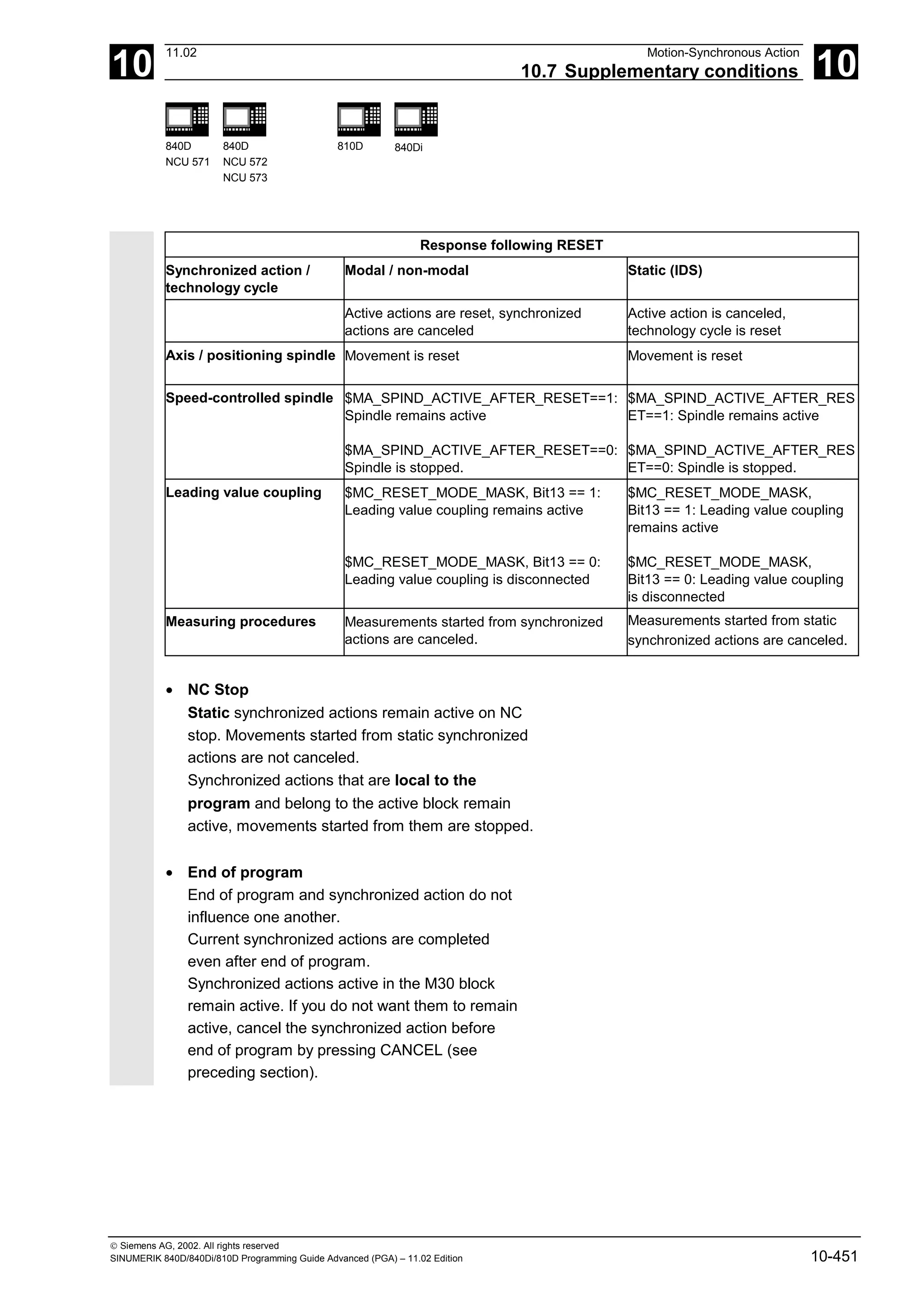
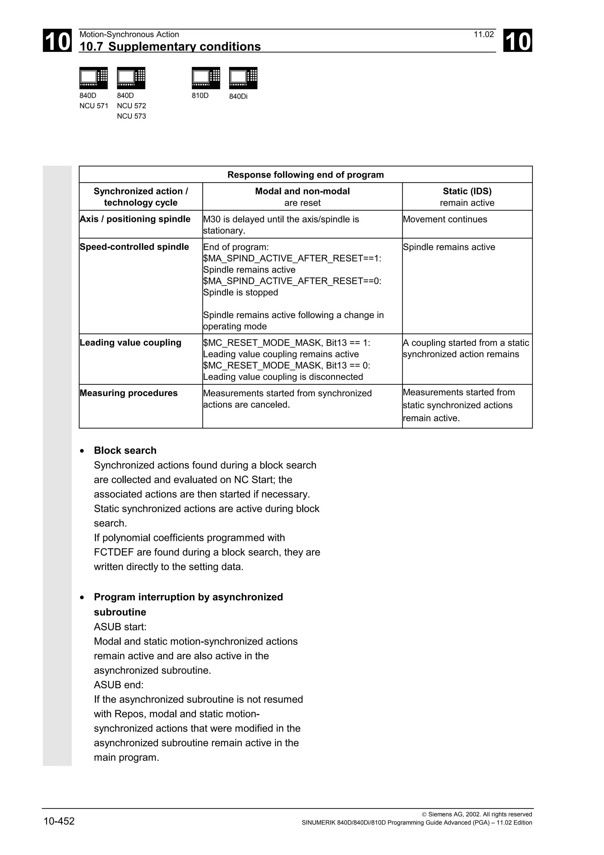
![10
11.02 Motion-Synchronous Action
10.7 Supplementary conditions 10
840D
NCU 571
840D
NCU 572
NCU 573
810D 840Di
Siemens AG, 2002. All rights reserved
SINUMERIK 840D/840Di/810D Programming Guide Advanced (PGA) – 11.02 Edition 10-453
• Repositioning
On repositioning REPOS, the synchronized
actions that were active in the interrupted block
are reactivated.
Modal synchronized actions changed from the
asynchronized subroutine are not active after
REPOS when the rest of the block is executed.
Polynomial coefficients programmed with
FCTDEF are not affected by asynchronized
subroutines and REPOS. No matter where they
were programmed, they can be used at any time
in the asynchronized subroutine and in the main
program after execution of REPOS.
• Deselection with CANCEL
If an active synchronized action is deselected
with CANCEL, this does not affect the active
action. Positioning movements are terminated in
accordance with programming.
The CANCEL command is used to interrupt a
modally or statically active synchronized action.
If a synchronized action is canceled while the
positioning axis movement that was activated
from it is still active, the positioning axis
movement is interrupted. If this is not required,
the axis movement can be decelerated before the
CANCEL command with axial deletion of
distance-to-go:
Example:
ID=17 EVERY $A_IN[3]==1 DO POS[X]=15 FA[X]=1500 ;Start positioning axis movement
...
WHEN ... DO DELDTG(X) ;End positioning axis movement
CANCEL(1)
▀](https://image.slidesharecdn.com/fadaladvancedprogrammingmanual-220505063253/75/Fadal-Advanced-Programming-Manual-pdf-453-2048.jpg)

![11
Oscillation 11.02
11.1 Asynchronous oscillation 11
840D
NCU 571
840D
NCU 572
NCU 573
810D 840Di
Siemens AG, 2002. All rights reserved
11-456 SINUMERIK 840D/840Di/810D Programming Guide Advanced (PGA) – 11.02 Edition
11.1 Asynchronous oscillation
Explanation of the commands
OSP1[axis]=
OSP2[axis]=
Position of reversal point 1
Position of reversal point 2
OST1[axis]=
OST2[axis]=
Stopping time at reversal points in seconds
FA[axis]= Feed for oscillating axis
OSCTRL[axis]= (Set, reset options)
OSNSC[axis]= Number of spark-out strokes
OSE[axis]= End position
OS[axis]= 1 = activate oscillation; 0 = deactivate oscillation
Function
An oscillating axis travels back and forth between
two reversal points 1 and 2 at a defined feedrate,
until the oscillating motion is deactivated.
Other axes can be interpolated as desired during the
oscillating motion.
A path movement or a positioning axis can be used
to achieve a constant infeed, however, there is no
relationship between the oscillating movement and
the infeed movement.](https://image.slidesharecdn.com/fadaladvancedprogrammingmanual-220505063253/75/Fadal-Advanced-Programming-Manual-pdf-456-2048.jpg)
![11
11.02 Oscillation
11.1 Asynchronous oscillation 11
840D
NCU 571
840D
NCU 572
NCU 573
810D 840Di
Siemens AG, 2002. All rights reserved
SINUMERIK 840D/840Di/810D Programming Guide Advanced (PGA) – 11.02 Edition 11-457
The oscillating axis
For the oscillating axis, the following applies:
• Any axis can be used as an oscillating axis.
• Several oscillating axes can be active
simultaneously (maximum: number of positioning
axes).
• Linear interpolation G1is always active for the
oscillating axis – irrespective of the G command
currently valid in the program.
The oscillating axis can
• act as an input axis for a dynamic transformation
• act as a guide axis for gantry and combined-
motion axes
• be traversed
– without jerk limitation (BRISK) or
– with jerk limitation (SOFT) or
– with acceleration curve with a knee
(as for positioning axes).
Oscillation reversal points
The current offsets must be taken into account when
oscillation positions are defined:
• Absolute specification
OSP1[Z]=value
Position of reversal point = sum of offsets +
programmed value
• Relative specification
OSP1[Z]=IC(value)
Position of reversal point = reversal point 1 +
programmed value
Example:
N10 OSP1[Z]=100 OSP2[Z]=110
.
.
N40 OSP1[Z]=IC(3)](https://image.slidesharecdn.com/fadaladvancedprogrammingmanual-220505063253/75/Fadal-Advanced-Programming-Manual-pdf-457-2048.jpg)
![11
Oscillation 11.02
11.1 Asynchronous oscillation 11
840D
NCU 571
840D
NCU 572
NCU 573
810D 840Di
Siemens AG, 2002. All rights reserved
11-458 SINUMERIK 840D/840Di/810D Programming Guide Advanced (PGA) – 11.02 Edition
Properties of asynchronized oscillation
• Asynchronized oscillation is active beyond block
limits on an axis-specific basis.
• Block-oriented activation of the oscillation
movement is ensured by the parts program.
• Combined interpolation of several axes and
superimposing of oscillation paths are not
possible.
Setting data
The setting data necessary for asynchronized oscillation
can be set in the parts program.
If the setting data are described directly in the
program, the change takes effect during
preprocessing. A synchronized response can be
achieved by means of a STOPRE.
Example:
Oscillation with online change
of reversal position
$SA_OSCILL_REVERSE_POS1[Z]=-10
$SA_OSCILL_REVERSE_POS2[Z]=10
G0 X0 Z0
WAITP(Z)
ID=1 WHENEVER $AA_IM[Z] < $$AA_OSCILL_REVERSE_POS1[Z] DO $AA_OVR[X]=0
ID=2 WHENEVER $AA_IM[Z] < $$AA_OSCILL_REVERSE_POS2[Z] DO $AA_OVR[X]=0
;If the actual value of the oscillation axis
;has exceeded the reversal point,
;the infeed axis is stopped.
OS[Z]=1 FA[X]=1000 POS[X]=40 ;Switch on oscillation
OS[Z]=0 ;Switch off oscillation
M30](https://image.slidesharecdn.com/fadaladvancedprogrammingmanual-220505063253/75/Fadal-Advanced-Programming-Manual-pdf-458-2048.jpg)
![11
11.02 Oscillation
11.1 Asynchronous oscillation 11
840D
NCU 571
840D
NCU 572
NCU 573
810D 840Di
Siemens AG, 2002. All rights reserved
SINUMERIK 840D/840Di/810D Programming Guide Advanced (PGA) – 11.02 Edition 11-459
Notes on individual functions
The following addresses allow asynchronized
oscillation to be activated and controlled from the
parts program.
The programmed values are entered in the
corresponding setting data with block
synchronization during the main run and remain
active until changed again.
Activate, deactivate oscillation: OS
OS[axis] = 1: Activate
OS[axis] = 0: Deactivate
WAITP (axis):
• If oscillation is to be performed with a geometry
axis, you must enable this axis for oscillation with
WAITP.
• When oscillation has finished, this command is
used to enter the oscillating axis as a positioning
axis again for normal use.
Stopping times at reversal points:
OST1, OST2
Hold time Movement in exact stop area at reversal point
-2 Interpolation is continued without waiting for exact stop
-1 Wait for exact stop coarse
0 Wait for exact stop fine
>0 Wait for exact stop fine and then wait for stopping time
The unit for the stopping time is identical to the
stopping time programmed with G4.
Note
Oscillation with motion-synchronous action and
stopping times "OST1/OST2”.
When the stopping times have elapsed, the internal
block change takes place during oscillation (visible at
the new residual paths of the axes). When block
change has been completed, the deactivation function
is checked. During checking, the deactivation function
is defined according to the control setting for the
"OSCTRL" sequence of motions.](https://image.slidesharecdn.com/fadaladvancedprogrammingmanual-220505063253/75/Fadal-Advanced-Programming-Manual-pdf-459-2048.jpg)
![11
11.02 Oscillation
11.1 Asynchronous oscillation 11
840D
NCU 571
840D
NCU 572
NCU 573
810D 840Di
Siemens AG, 2002. All rights reserved
SINUMERIK 840D/840Di/810D Programming Guide Advanced (PGA) – 11.02 Edition 11-461
Option value Meaning
0 When the oscillation is deactivated, stop at the next reversal point (default)
only possible by resetting values 1 and 2
1 When the oscillation is deactivated, stop at reversal point 1
2 When the oscillation is deactivated, stop at reversal point 2
3 When the oscillation is deactivated, do not approach reversal point if no
spark-out strokes are programmed
4 Approach end position after spark-out
8 If the oscillation movement is canceled by deletion of the distance-to-go:
then execute spark-out strokes and approach end position if appropriate
16 If the oscillation movement is canceled by deletion of the distance-to-go:
reversal position is approached as with deactivation
32 New feed is only active after the next reversal point
64 FA = 0: Path overlay is active
FA 0: Speed overlay is active
128 For rotary axis DC (shortest path)
256 0=The sparking out stroke is a dual stroke.(default) 1=single stroke.
Several options are appended with plus characters.
Example:
OSCTRL[Z] = (1+4,16+32+64)](https://image.slidesharecdn.com/fadaladvancedprogrammingmanual-220505063253/75/Fadal-Advanced-Programming-Manual-pdf-461-2048.jpg)
![11
Oscillation 11.02
11.1 Asynchronous oscillation 11
840D
NCU 571
840D
NCU 572
NCU 573
810D 840Di
Siemens AG, 2002. All rights reserved
11-462 SINUMERIK 840D/840Di/810D Programming Guide Advanced (PGA) – 11.02 Edition
Programming example
Oscillating axis Z is to oscillate between 10 and 100.
Approach reversal point 1 with exact stop fine,
reversal point 2 with exact stop coarse. Machining
takes place with feedrate 250 for the oscillating axis.
At the end of the machining operation, 3 spark-out
strokes must be executed and end position 200
approached with the oscillating axis.
The feed for the infeed axis is 1, the end of the
infeed in the X direction is at 15.
WAITP(X,Y,Z) Starting position
G0 X100 Y100 Z100 Switch over in positioning axis operation
N40 WAITP(X,Z)
N50 OSP1[Z]=10 OSP2[Z]=100 ->
-> OSE[Z]=200 ->
-> OST1[Z]=0 OST2[Z]=–1 ->
-> FA[Z]=250 FA[X]=1 ->
-> OSCTRL[Z]=(4,0) ->
-> OSNSC[Z]=3 ->
N60 OS[Z]=1
Reversal point 1, reversal point 2
End position
Stopping time at U1: exact stop fine
Stopping time at U2: exact stop coarse
Feed for oscillating axis, infeed axis
Setting options
Three spark-out strokes
Start oscillation
N70 WHEN $A_IN[3]==TRUE ->
-> DO DELDTG(X)
Deletion of distance-to-go
N80 POS[X]=15 Starting position X axis
N90 POS[X]=50
N100 OS[Z]=0 Stop oscillation
M30
-> can be programmed in a single block.](https://image.slidesharecdn.com/fadaladvancedprogrammingmanual-220505063253/75/Fadal-Advanced-Programming-Manual-pdf-462-2048.jpg)
![11
11.02 Oscillation
11.2 Oscillation controlled via synchronous actions 11
840D
NCU 571
840D
NCU 572
NCU 573
810D 840Di
Siemens AG, 2002. All rights reserved
SINUMERIK 840D/840Di/810D Programming Guide Advanced (PGA) – 11.02 Edition 11-463
11.2 Oscillation controlled via synchronous actions
Programming:
1. Define parameters for oscillation
2. Define motion-synchronous actions
3. Assign axes, define infeed
Parameters for oscillation
OSP1[oscillating axis]= Position of reversal point 1
OSP2[oscillating axis]= Position of reversal point 2
OST1[oscillating axis]= Stopping time at reversal point 1 in seconds
OST2[oscillating axis]= Stopping time at reversal point 2 in seconds
FA[OscillationAxis]= Feed for oscillating axis
OSCTRL[OscillationAxis]= Set or reset options
OSNSC[oscillating axis]= Number of spark-out strokes
OSE[OscillationAxis]= End position
WAITP(OscillationAxis) Enable axis for oscillation
Axis assignment, infeed
OSCILL[OscillationAxis] = (InfeedAxis1, InfeedAxis2, InfeedAxis3)
POSP[InfeedAxis] = (Endpos, Partial length, Mode)
OSCILL Assign infeed axis or axes for oscillating axis
POSP Define complete and partial infeeds (see Chapter 3)
Endpos End position for the infeed axis after all partial infeeds have
been traversed.
Partial length Length of the partial infeed at reversal point/reversal area
Mode Division of the complete infeed into partial infeeds
0 = Two residual steps of equal size (default);
1 = All partial infeeds of equal size
Motion-synchronized actions
WHEN… … DO when ... , do ...
WHENEVER … DO whenever ... , do ...](https://image.slidesharecdn.com/fadaladvancedprogrammingmanual-220505063253/75/Fadal-Advanced-Programming-Manual-pdf-463-2048.jpg)
![11
11.02 Oscillation
11.2 Oscillation controlled via synchronous actions 11
840D
NCU 571
840D
NCU 572
NCU 573
810D 840Di
Siemens AG, 2002. All rights reserved
SINUMERIK 840D/840Di/810D Programming Guide Advanced (PGA) – 11.02 Edition 11-465
Assignment of oscillating and infeed axes
OSCILL
OSCILL[oscillating axis] = (infeed axis1, infeed axis2, infeed axis3)
The axis assignments and the start of the oscillation
movement are defined with the OSCILL command.
Up to 3 infeed axes can be assigned to an oscillating
axis.
Before oscillation starts, the synchronization
conditions must be defined for the behavior of the
axes.
Define infeeds: POSP
POSP[InfeedAxis] = (EndPosition, Part, Mode)
The following are declared to the control with the POSP
command:
• Complete infeed (with reference to end position)
• The length of the partial infeed at the reversal
point or in the reversal area
• The partial infeed response when the end
position is reached (with reference to mode)
Mode = 0 The distance-to-go to the destination point for the last two partial infeeds
is divided into 2 equal steps (default setting).
Mode = 1 All partial infeeds are of equal size. They are calculated from the
complete infeed.](https://image.slidesharecdn.com/fadaladvancedprogrammingmanual-220505063253/75/Fadal-Advanced-Programming-Manual-pdf-465-2048.jpg)
![11
11.02 Oscillation
11.2 Oscillation controlled via synchronous actions 11
840D
NCU 571
840D
NCU 572
NCU 573
810D 840Di
Siemens AG, 2002. All rights reserved
SINUMERIK 840D/840Di/810D Programming Guide Advanced (PGA) – 11.02 Edition 11-467
Infeed in reversal area
The infeed motion must start within a reversal area
before the reversal point is reached.
These synchronized actions inhibit the infeed
movement until the oscillating axis is within the
reversal area.
The following instructions are used subject to the
above assumptions:
Reversal area 1:
WHENEVER $AA_IM[Z]>$SA_OSCILL_REVERSE_POS1[Z]+ii1 DO $AA_OVR[X]=0
Whenever
greater than
then
the current position of oscillating axis in the MCS is
the start of reversal area 1
set the axial override of the infeed axis to 0%.
Reversal area 2:
WHENEVER $AA_IM[Z] <$SA_OSCILL_REVERSE_POS2[Z]+ii2 DO $AA_OVR[X]=0
Whenever
less than
then
the current position of oscillating axis in the MCS is
the start of reversal area 2
set the axial override of the infeed axis to 0%.](https://image.slidesharecdn.com/fadaladvancedprogrammingmanual-220505063253/75/Fadal-Advanced-Programming-Manual-pdf-467-2048.jpg)
![11
Oscillation 11.02
11.2 Oscillation controlled via synchronous actions 11
840D
NCU 571
840D
NCU 572
NCU 573
810D 840Di
Siemens AG, 2002. All rights reserved
11-468 SINUMERIK 840D/840Di/810D Programming Guide Advanced (PGA) – 11.02 Edition
Infeed at reversal point
As long as the oscillating axis has not reached the
reversal point, no movement takes place on the infeed
axis.
The following instructions are used subject to the
above assumptions:
Reversal point 1:
WHENEVER $AA_IM[Z]<>$SA_OSCILL_REVERSE_POS1[Z] DO $AA_OVR[X]=0 ->
-> $AA_OVR[Z]=100
Whenever
greater or less than
then
and
the current position of oscillating axis Z in the MCS is
the position of reversal point 1
set the axial override of infeed axis X to 0%
set the axial override of oscillating axis Z to 100%.
Reversal point 2:
For reversal point 2:
WHENEVER $AA_IM[Z]<>$SA_OSCILL_REVERSE_POS2[Z] DO $AA_OVR[X]=0 ->
-> $AA_OVR[Z]=100
Whenever
greater or less than
then
and
the current position of oscillating axis Z in the MCS is
the position of reversal point 2
set the axial override of infeed axis X to 0%
set the axial override of oscillating axis Z to 100%.](https://image.slidesharecdn.com/fadaladvancedprogrammingmanual-220505063253/75/Fadal-Advanced-Programming-Manual-pdf-468-2048.jpg)
![11
11.02 Oscillation
11.2 Oscillation controlled via synchronous actions 11
840D
NCU 571
840D
NCU 572
NCU 573
810D 840Di
Siemens AG, 2002. All rights reserved
SINUMERIK 840D/840Di/810D Programming Guide Advanced (PGA) – 11.02 Edition 11-469
Stop oscillation motion at reversal point
The oscillation axis is stopped at the reversal point,
the infeed motionstarts at the same time.
The oscillating motion is continued when the infeed
movement is complete.
This synchronized action can also be used to start
the infeed movement if this has been stopped by a
previous synchronized action which is still active.
The following instructions are used subject to the
above assumptions:
Reversal point 1:
WHENEVER $SA_IM[Z]==$SA_OSCILL_REVERSE_POS1[Z]DO $AA_OVR[Z]=0 ->
-> $AA_OVR[X] = 100
Whenever
equal to
then
and
the current position of oscillating axis in the MCS is
the position of reversal point 1
set the axial override of the oscillating axis to 0%
set the axial override of the infeed axis to 100%.
Reversal point 2:
WHENEVER $SA_IM[Z] ==$SA_OSCILL_REVERSE_POS2[Z]DO $AA_OVR[Z]= 0 ->
-> $AA_OVR[X]=100
Whenever
equal to
then
and
the current position of oscillating axis in the MCS is
the position of reversal point 2
set the axial override of the oscillating axis to 0%
set the axial override of the infeed axis to 100%.](https://image.slidesharecdn.com/fadaladvancedprogrammingmanual-220505063253/75/Fadal-Advanced-Programming-Manual-pdf-469-2048.jpg)
![11
Oscillation 11.02
11.2 Oscillation controlled via synchronous actions 11
840D
NCU 571
840D
NCU 572
NCU 573
810D 840Di
Siemens AG, 2002. All rights reserved
11-470 SINUMERIK 840D/840Di/810D Programming Guide Advanced (PGA) – 11.02 Edition
Online evaluation of reversal point
If there is a main run variable coded with $$ on the
right of the comparison, then the two variables are
evaluated and compared with one another
continuously in the IPO cycle.
Please refer to Section "Motion-synchronized
actions" for more information.
Restart oscillation movement
This synchronized action is used to continue the
oscillating movement when the partial infeed
movement is complete.
The following instructions are used subject to the
above assumptions:
WHENEVER $AA_DTEPW[X]==0 DO $AA_OVR[Z]= 100
Whenever
equal to
then
the distance-to-go for the partial infeed on infeed axis X in the WCS is
zero
set the axial override of the oscillating axis to 100%.](https://image.slidesharecdn.com/fadaladvancedprogrammingmanual-220505063253/75/Fadal-Advanced-Programming-Manual-pdf-470-2048.jpg)
![11
11.02 Oscillation
11.2 Oscillation controlled via synchronous actions 11
840D
NCU 571
840D
NCU 572
NCU 573
810D 840Di
Siemens AG, 2002. All rights reserved
SINUMERIK 840D/840Di/810D Programming Guide Advanced (PGA) – 11.02 Edition 11-471
Next partial infeed
When infeed is complete, a premature start of the
next partial infeed must be inhibited.
A channel-specific marker ($AC_MARKER[Index])
is used for this purpose. It is enabled at the end of
the partial infeed (partial distance-to-go ≡ 0) and
deleted when the axis leaves the reversal area. A
synchronized action is then used to inhibit the next
infeed movement.
On the basis of the given assumptions, the following
instructions apply for reversal point 1:
1. Set marker
WHENEVER $AA_DTEPW[X] == 0 DO $AC_MARKER[1]=1
Whenever
equal to
then
the distance-to-go for the partial infeed on infeed axis X in the WCS is
zero
set the marker with index 1 to 1.
2. Clear marker
WHENEVER $AA_IM[Z]<>$SA_OSCILL_REVERSE_POS1[Z] D0 $AC_MARKER[1]=0
Whenever
greater or less than
then
the current position of oscillating axis Z in the MCS is
the position of reversal point 1
set marker 1 to 0.
3. Inhibit infeed
WHENEVER $AC_MARKER[1]==1 DO $AA_OVR[X]=0
Whenever
equal to
then
marker 1 is
1,
set the axial override of the infeed axis to 0%.](https://image.slidesharecdn.com/fadaladvancedprogrammingmanual-220505063253/75/Fadal-Advanced-Programming-Manual-pdf-471-2048.jpg)
![11
Oscillation 11.02
11.2 Oscillation controlled via synchronous actions 11
840D
NCU 571
840D
NCU 572
NCU 573
810D 840Di
Siemens AG, 2002. All rights reserved
11-472 SINUMERIK 840D/840Di/810D Programming Guide Advanced (PGA) – 11.02 Edition
Programming example
No infeed is to take place at reversal point 1. At
reversal point 2, the infeed is to start at a distance of
ii2 before reversal point 2 and the oscillating axis is
not to wait at the reversal point for the end of the
partial infeed. Axis Z is the oscillating axis and axis X
the infeed axis.
1.0
2.0
3.0
4.0
5.0
X
Z
0 10 20 30 40 50 60 70
Approach reversal point 1
and 3 sparking-out strokes
Approach
end position
Program extract
1. Define parameters for oscillation
DEF INT ii2 Define variable for reversal area 2
OSP1[Z]=10 OSP2[Z]=60 Define reversal points 1 and 2
OST1[Z]=0 OST2[Z]=0 Reversal point 1: exact stop fine
Reversal point 2: exact stop fine
FA[Z]=150 FA[X]=0.5 Oscillating axis Z feedrate, infeed axis X
feedrate
OSCTRL[Z]=(2+8+16,1) Deactivate oscillating motion at reversal
point 2; after delete DTG spark-out and
approach end position; after delete DTG
approach reversal position
OSNC[Z]=3 3 spark-out strokes
OSE[Z]=70 End position = 70
ii2=2 Set reversal area
WAITP(Z) Enable oscillation for Z axis](https://image.slidesharecdn.com/fadaladvancedprogrammingmanual-220505063253/75/Fadal-Advanced-Programming-Manual-pdf-472-2048.jpg)
![11
11.02 Oscillation
11.2 Oscillation controlled via synchronous actions 11
840D
NCU 571
840D
NCU 572
NCU 573
810D 840Di
Siemens AG, 2002. All rights reserved
SINUMERIK 840D/840Di/810D Programming Guide Advanced (PGA) – 11.02 Edition 11-473
2. Motion-synchronized actions
WHENEVER $AA_IM[Z]<$SA_OSCILL_REVERSE_POS2[Z]–ii2 DO ->
-> $AA_OVR[X]=0 $AC_MARKER[0]=0
Whenever
less than
then
and
the current position of oscillating axis Z in the MCS is
the start of reversal area 2
set the axial override of infeed axis X to 0%
set the marker with index 0 to value 0.
WHENEVER $AA_IM[Z]>=$SA_OSCILL_REVERSE_POS2[Z] DO $AA_OVR[Z]=0
Whenever
greater or equal to
then
the current position of oscillating axis Z in the MCS is
the position of reversal point 2
set the axial override of oscillating axis Z to 0%.
WHENEVER $AA_DTEPW[X]==0 DO $AC_MARKER[0]=1
Whenever
equal to
then
the distance-to-go of the partial infeed is
0,
set the marker with index 0 to value 1.
WHENEVER $AC_MARKER[0]==1 DO $AA_OVR[X]=0 $AA_OVR[Z]=100
Whenever
equal to
then
the marker with index 0 is
1,
set the axial override of infeed axis X to 0% in order to inhibit premature
infeed (oscillating axis Z has not yet left reversal area 2 but infeed axis X is
ready for a new infeed)
set the axial override of oscillating axis Z to 100% (this cancels the 2nd
synchronized action).
-> must be programmed in a separate block
3. Start oscillation
OSCILL[Z]=(X) POSP[X]=(5,1,1) Start axes
Assign axis X as the infeed axis for
oscillating axis Z.
Axis X is to travel to end position 5 in
steps of 1.
M30 End of program
n](https://image.slidesharecdn.com/fadaladvancedprogrammingmanual-220505063253/75/Fadal-Advanced-Programming-Manual-pdf-473-2048.jpg)

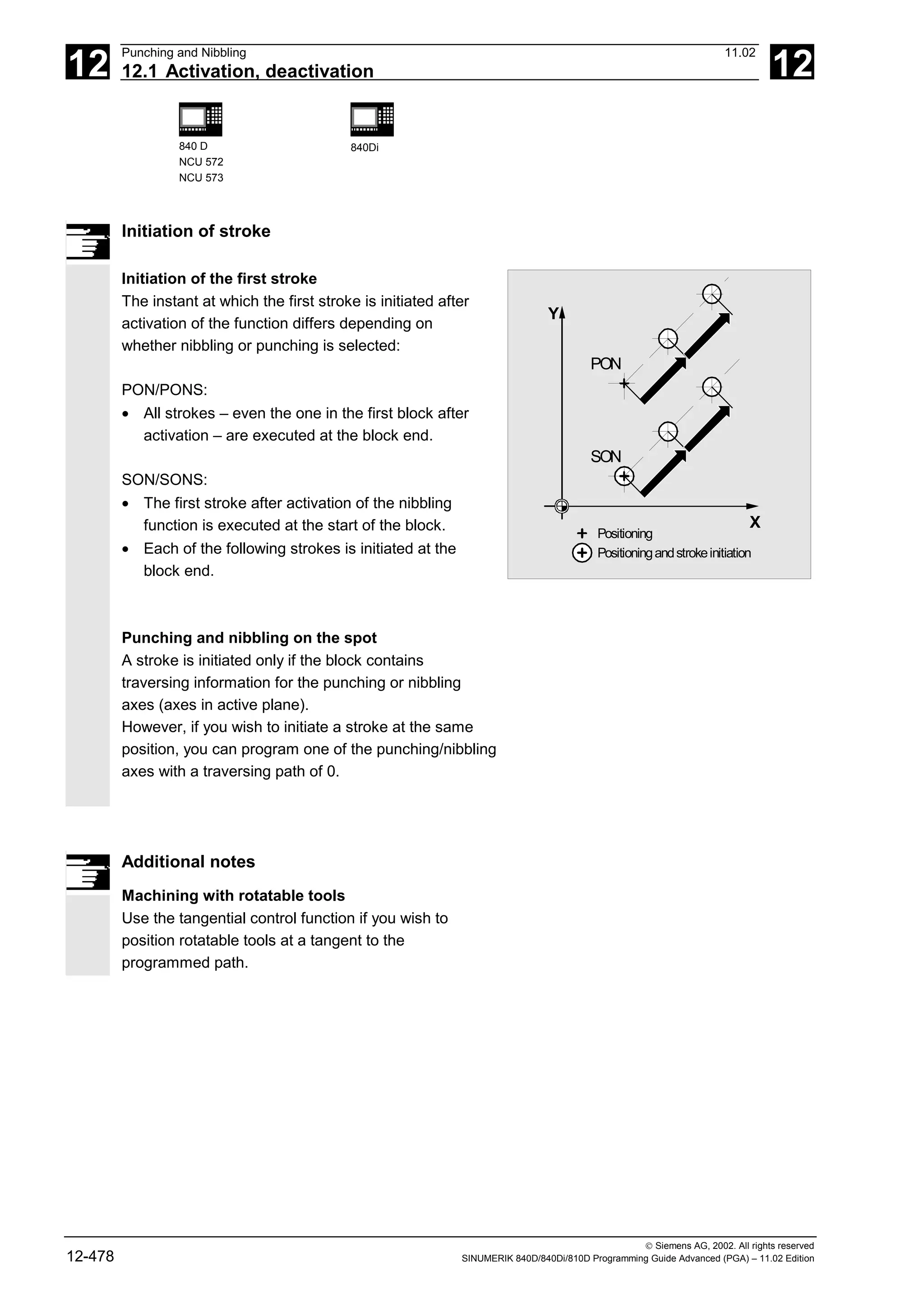
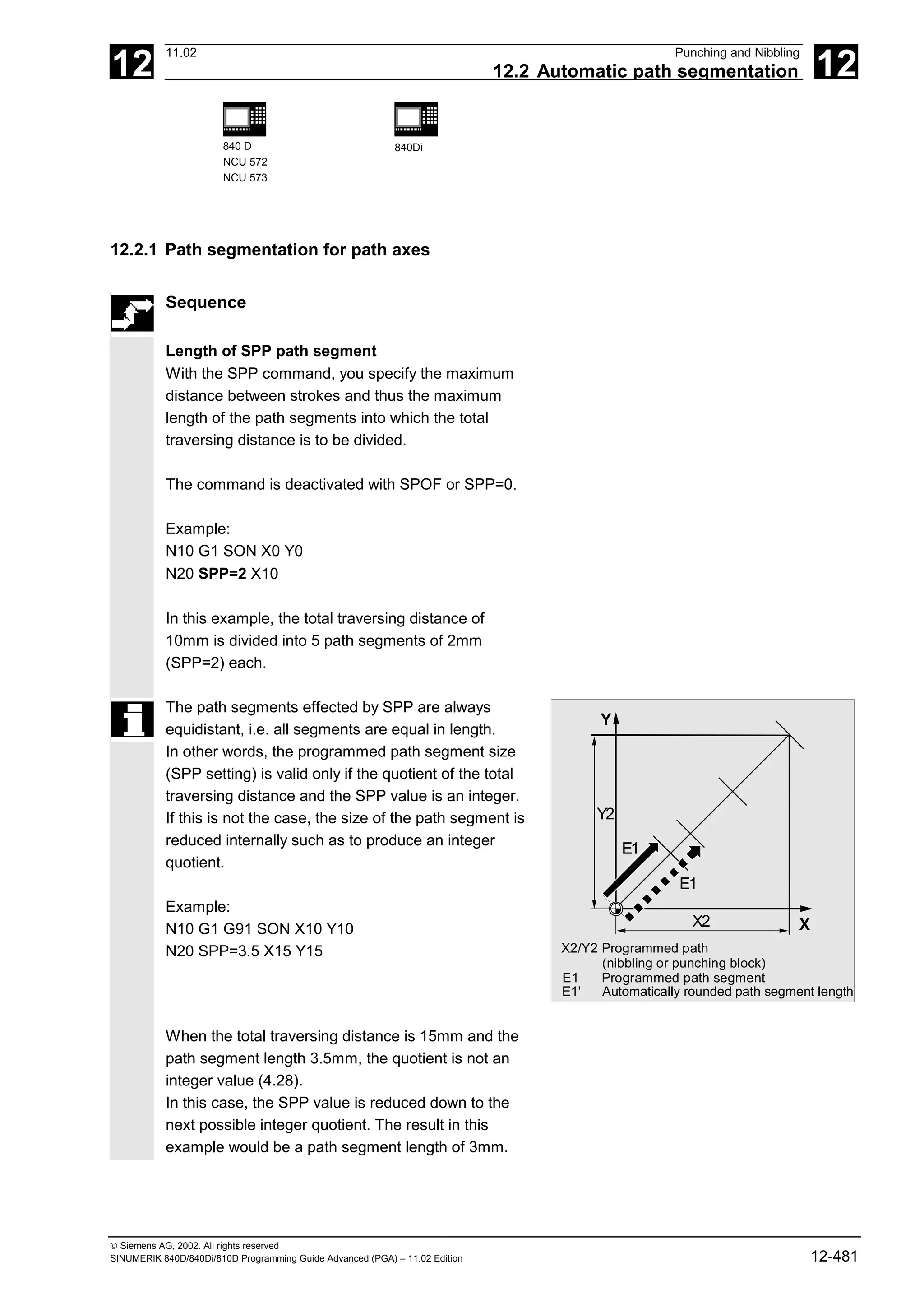
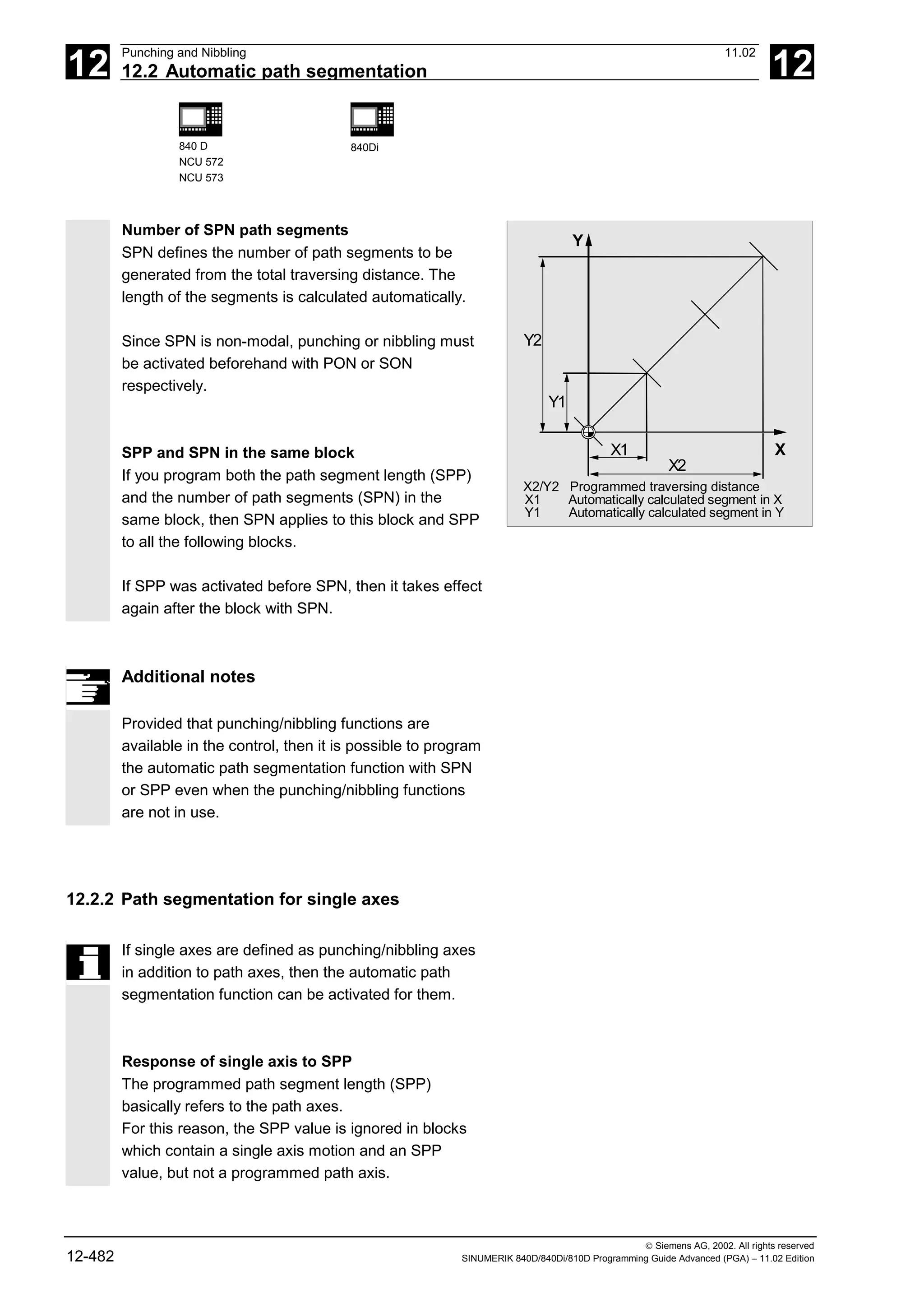
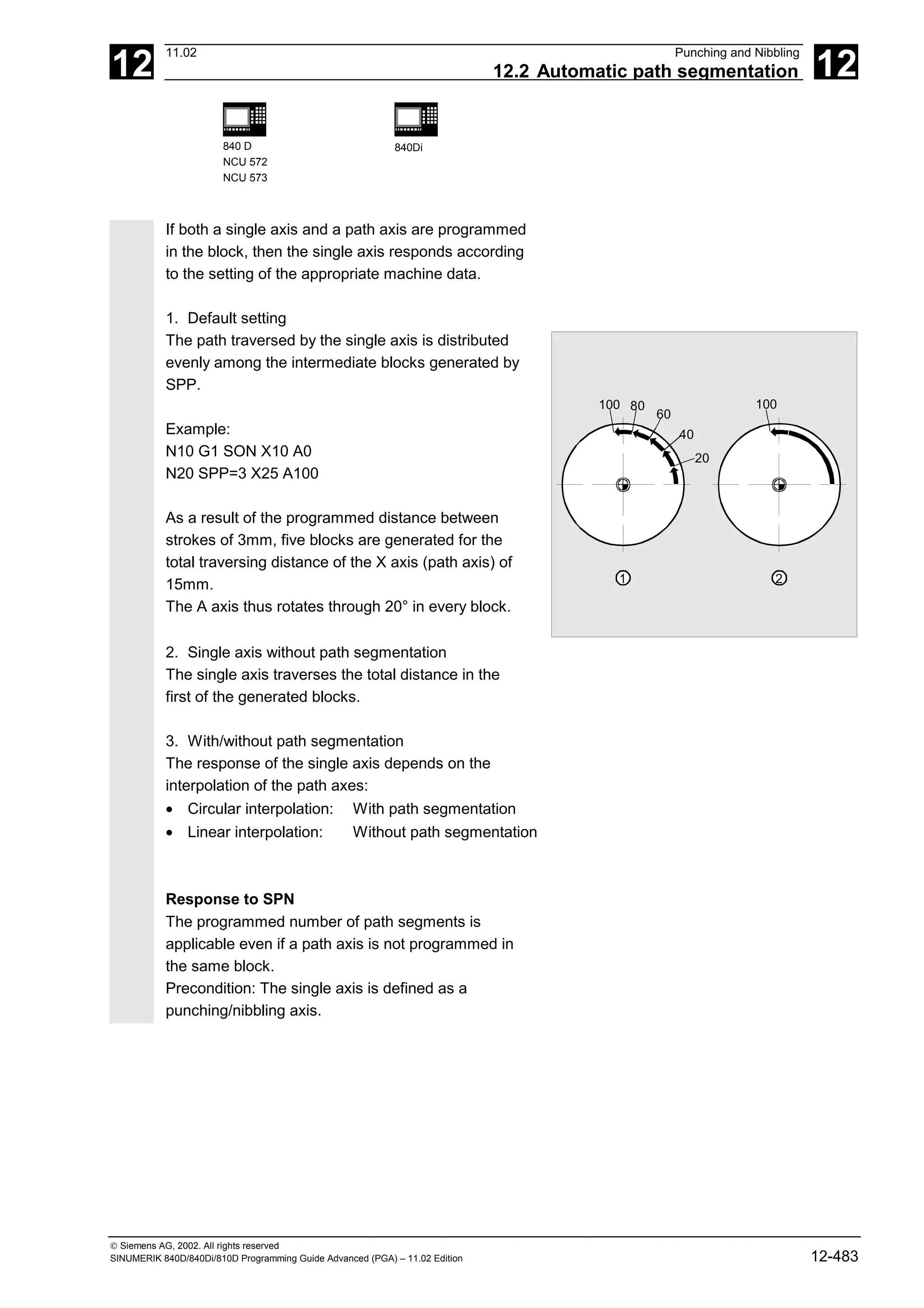
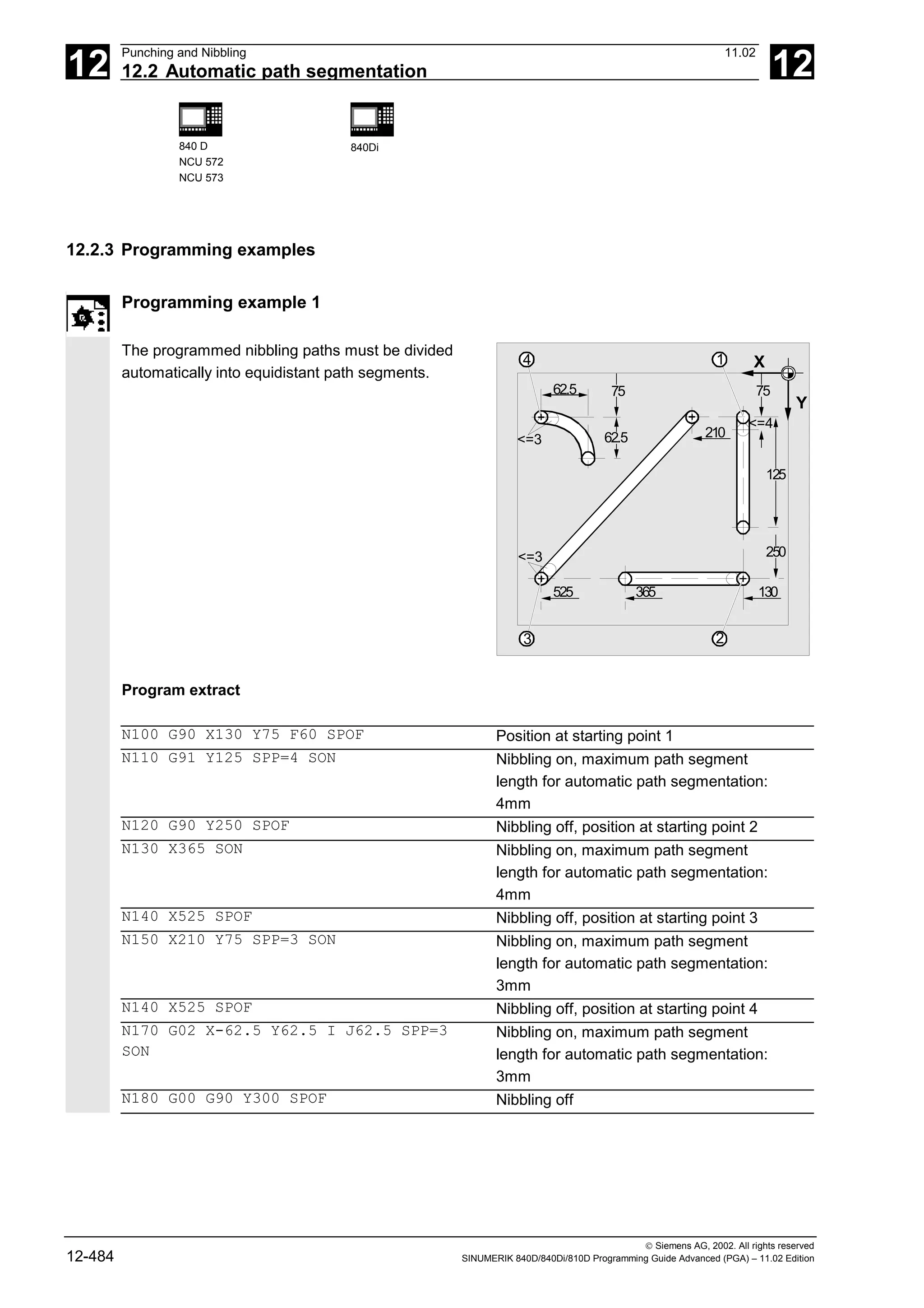
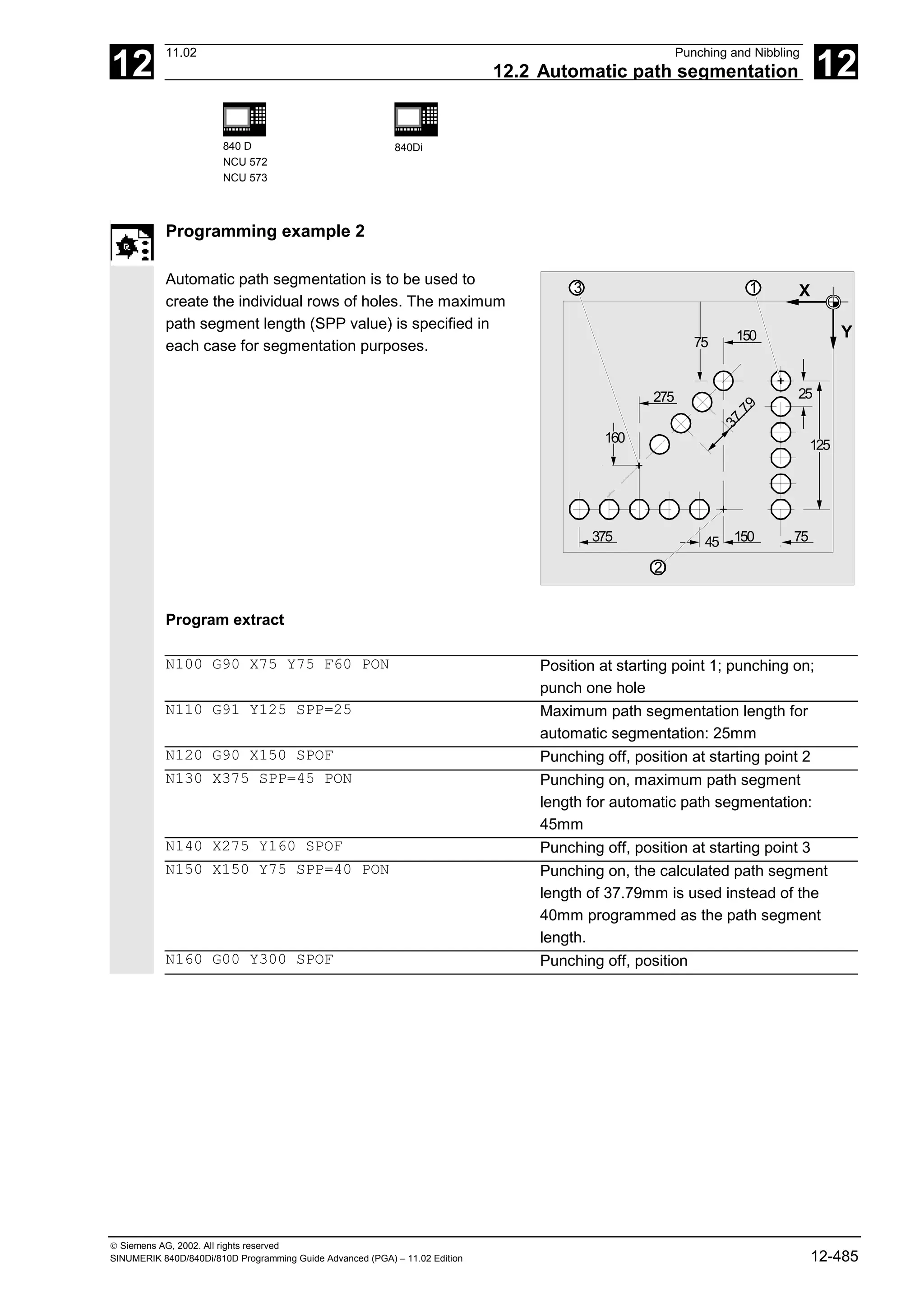


![13
11.02 Additional Functions
13.1 Axis functions AXNAME, SPI, ISAXIS, AXSTRING 13
840D
NCU 571
840D
NCU 572
NCU 573
810D 840Di
Siemens AG, 2002. All rights reserved
SINUMERIK 840D/840Di/810D Programming Guide Advanced (PGA) – 11.02 Edition 13-489
13.1 Axis functions AXNAME, SPI, ISAXIS, AXSTRING
(SW 6 and higher)
Programming
AXNAME("TRANSVERSE AXIS")
AX[AXNAME("string")]
AXSTRING ( (SPI(n) )
SPI(n)(spindle number)
ISAXIS(geometry axis number)
Explanation of the commands
AXNAME Converts an input string to an axis identifier.
The input string must contain valid axis names.
SPI Converts a spindle number to an axis identifier. The parameter
transferred must contain a valid spindle number.
n Spindle number
AXSTRING Up until SW 5, the axis index of the axis which was assigned to the
spindle was output as spindle number.
From SW 6 the string is output with the associated spindle number.
AX Variable axis identifier
ISAXIS Checks whether the specified geometry axis exists.
Function
AXNAME is used, for example, to create generally
applicable cycles when the name of the axes are not
known (see also Section 13.10. "String functions").
SPI is used, for example, when axis functions are
used for a spindle, e.g. the synchronized spindle.
ISAXIS is used in universal cycles in order to
ensure that a specific geometry axis exists and thus
that any following $P_AXNX call is not aborted with
an error message.
(SW 6 and higher)
Extensions SPI(n):
The axis function SPI(n) can now also be used for
reading and writing frame components, for example,
for writing frames with syntax
$S_PFRAME[SPI](1),TR]=2.22.](https://image.slidesharecdn.com/fadaladvancedprogrammingmanual-220505063253/75/Fadal-Advanced-Programming-Manual-pdf-489-2048.jpg)
![13
Additional Functions 11.02
13.1 Axis functions AXNAME, SPI, ISAXIS, AXSTRING 13
840D
NCU 571
840D
NCU 572
NCU 573
810D 840Di
Siemens AG, 2002. All rights reserved
13-490 SINUMERIK 840D/840Di/810D Programming Guide Advanced (PGA) – 11.02 Edition
Additional programming of the axis position via
address AX[SPI(1)] = <axis position>
allows an axis to be traversed.
Troubleshooting for AXSTRING( SPI(n) )
When programming
AXSTRING( SPI(n) ) up to SW 5
the axis index of the axis which was assigned to the
spindle was output as spindle number.
Example:
Spindle 1 is assigned to the 5th axis.
($MA_SPIND_ASSIGN_TO_MACHAX[AX5]=1),
AXSTRING( SPI(1) ) returns the incorrect string
"S4"
With SW 6 and higher,
AXSTRING[ SPI(n) ]will output the string "Sn".
Example:
AXSTRING( SPI(2) ) returns string "S2"
Programming example
Move the axis defined as a facing axis.
OVRA[AXNAME("Transverse axis")]=10 Transverse axis
AX[AXNAME("Transverse axis")]=50.2 Final position for transverse axis
OVRA[SPI(1)]=70 Override for spindle 1
IF ISAXIS(1) == FALSE GOTOF CONTINUE Does abscissa exist?
AX[$P_AXN1]=100 Move abscissa
CONTINUE:](https://image.slidesharecdn.com/fadaladvancedprogrammingmanual-220505063253/75/Fadal-Advanced-Programming-Manual-pdf-490-2048.jpg)
![13
11.02 Additional Functions
13.2 Function call ISVAR ( ) (SW 6.3 and higher) 13
840D
NCU 571
840D
NCU 572
NCU 573
810D 840Di
Siemens AG, 2002. All rights reserved
SINUMERIK 840D/840Di/810D Programming Guide Advanced (PGA) – 11.02 Edition 13-491
13.2 Function call ISVAR ( ) (SW 6.3 and higher)
Programming
ISVAR ("variable identifier")
ISVAR (identifier, [value, value])
Explanation of the commands
Variable identifiers Transfer parameter of type string can be undimensioned, 1-dimen-
sional, or 2-dimensional
Identifier Identifier with a known variable with or without an array index as
machine data, setting data, system variable, or general variable
Value Function value of type BOOL
Structure
The transfer parameter can have the following
structure:
1. Undimensioned variable:
identifier
2. 1-dimensional variable without array index:
identifier[ ]
3. 1-dimensional variable with array index:
identifier[value]
4. 2-dimensional variable without array index:
identifier[ , ]
5. 2-dimensional variable with array index:
identifier[value, value]
Function
The ISVAR command is a function as defined in the
NC language with a:
• Function value of type BOOL
• Transfer parameter of type STRING
The ISVAR command returns TRUE,
if the transfer parameter contains a variable known
in the NC (machine data, setting data, system
variable, general variables such as GUD's).](https://image.slidesharecdn.com/fadaladvancedprogrammingmanual-220505063253/75/Fadal-Advanced-Programming-Manual-pdf-491-2048.jpg)
![13
Additional Functions 11.02
13.2 Function call ISVAR ( ) (SW 6.3 and higher) 13
840D
NCU 571
840D
NCU 572
NCU 573
810D 840Di
Siemens AG, 2002. All rights reserved
13-492 SINUMERIK 840D/840Di/810D Programming Guide Advanced (PGA) – 11.02 Edition
Checks
The following checks are make in accordance with
the transfer parameter:
• Does the identifier exist
• Is it a 1- or 2-dimensional array
• Is an array index permitted
Only if all this checks have a positive result will
TRUE be returned. If a check has a negative result
or if a syntax error has occurred, it will return FALSE.
Axial variables are accepted as an index for the axis
names but not checked.
Examples:
DEF INT VAR1
DEF BOOL IS_VAR=FALSE ; Transfer parameter is a general variable
N10 IS_VAR=ISVAR("VAR1") ; IS_VAR is TRUE in this case
DEF REAL VARARRAY[10,10]
DEF BOOL IS_VAR=FALSE ; Different syntax variations
N20
IS_VAR=ISVAR("VARARRAY[,]")
; IS_VAR is TRUE with a 2-dimensional array
N30 IS_VAR=ISVAR("VARARRAY") ; IS_VAR is TRUE, variable exists
N40 IS_VAR=ISVAR
("VARARRAY[8,11]")
; IS_VAR is FALSE, array index is not allowed
N50
IS_VAR=ISVAR("VARARRAY[8,8")
; IS_VAR is FALSE, syntax error for missing "]"
N60
IS_VAR=ISVAR("VARARRAY[,8]")
; IS_VAR is TRUE, array index is allowed
N70
IS_VAR=ISVAR("VARARRAY[8,]")
; IS_VAR is TRUE
DEF BOOL IS_VAR=FALSE ; Transfer parameter is a machine data
N100 IS_VAR=ISVAR
("$MC_GCODE_RESET_VALUES[
1]"
; IS_VAR is TRUE
DEF BOOL IS_VAR=FALSE ; Transfer parameter is a system variable
N10 IS_VAR=ISVAR("$P_EP") ; IS_VAR is TRUE in this case
N10 IS_VAR=ISVAR("$P_EP[X]") ; IS_VAR is TRUE in this case](https://image.slidesharecdn.com/fadaladvancedprogrammingmanual-220505063253/75/Fadal-Advanced-Programming-Manual-pdf-492-2048.jpg)
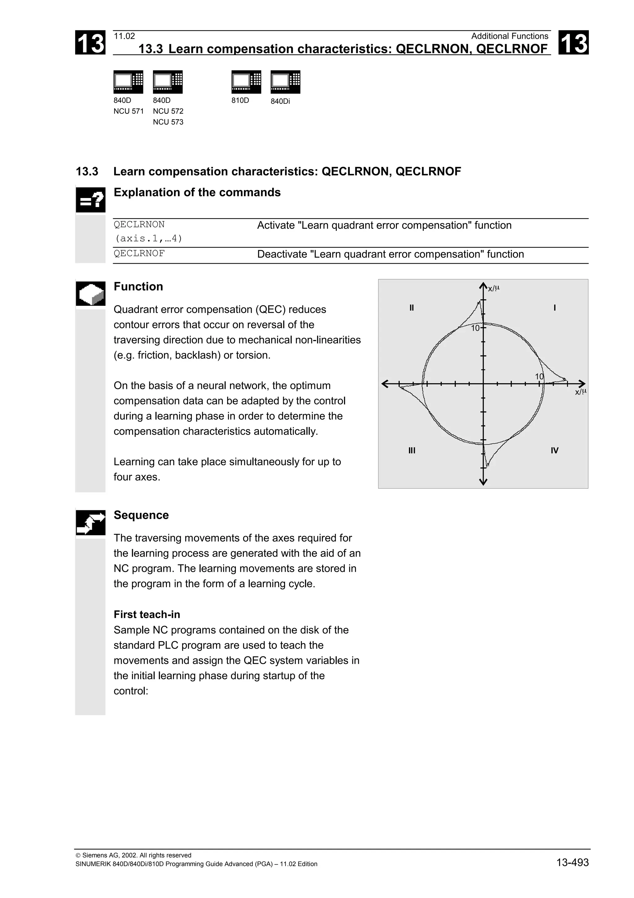
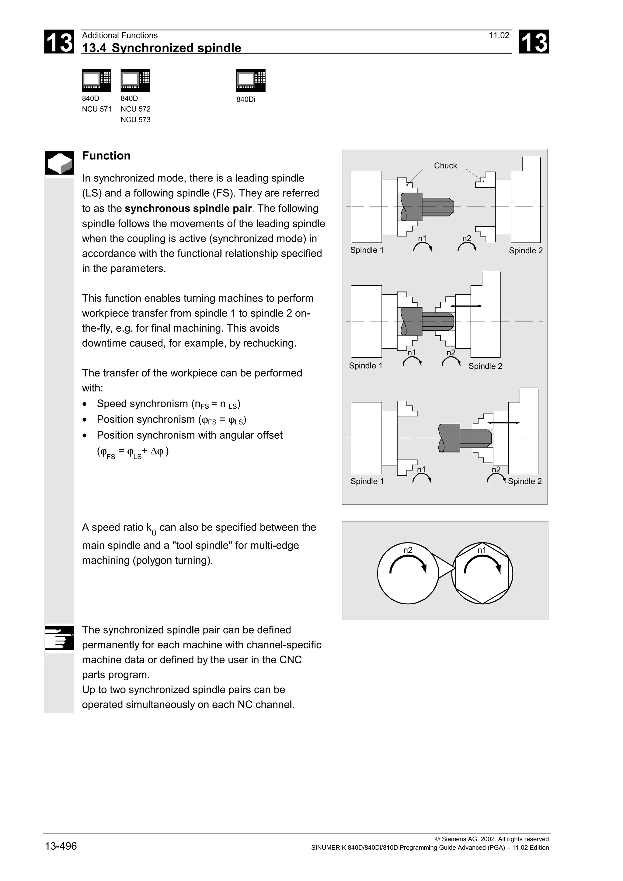
![13
Additional Functions 11.02
13.4 Synchronized spindle 13
840D
NCU 571
840D
NCU 572
NCU 573
840Di
Siemens AG, 2002. All rights reserved
13-498 SINUMERIK 840D/840Di/810D Programming Guide Advanced (PGA) – 11.02 Edition
Positioning the following spindle: Options
When the synchronized spindle coupling is active,
following spindles can also be positioned within the
±180° range independently of the motion initiated by
the master spindle.
Positioning SPOS
The following spindle can be interpolated with
SPOS=…
Please refer to Programming Guide "Fundamentals"
for more information about SPOS.
Example:
N30 SPOS[2]=IC(-90)
FA, ACC, OVRA:
Speed, acceleration
The position speeds and acceleration rates for
following spindles can be programmed with
FA[SPI(Sn)] or FA[Sn], ACC[SPI(Sn)] or ACC[Sn]
and OVRA[SPI(n)] or OVRA[Sn] (see Programming
Guide, Fundamentals). "n" stands for spindle
number 1...n.
Programmable block change WAITC
WAITC can be used to define the block change
behavior with various synchronism conditions
(coarse, fine, IPOSTOP) for continuation of the
program, e.g. after changes to coupling parameters
or positioning operations.
WAITC causes a delay in the insertion of new blocks
until the appropriate synchronism condition is
fulfilled, thereby allowing the synchronized state to
be processed faster.
If no synchronism conditions are specified, then the
block change behavior programmed/configured for
the relevant coupling applies.](https://image.slidesharecdn.com/fadaladvancedprogrammingmanual-220505063253/75/Fadal-Advanced-Programming-Manual-pdf-498-2048.jpg)
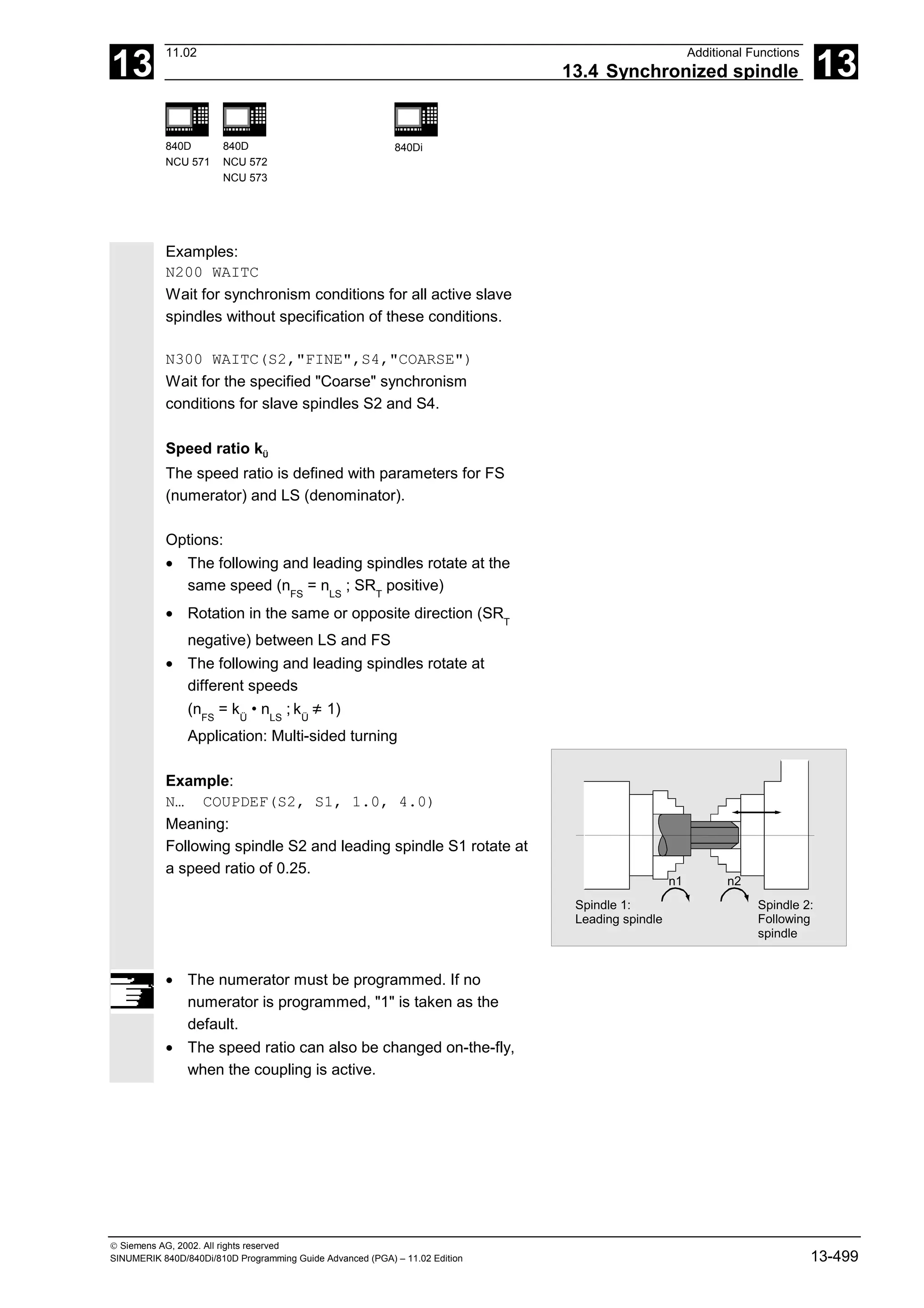
![13
11.02 Additional Functions
13.4 Synchronized spindle 13
840D
NCU 571
840D
NCU 572
NCU 573
840Di
Siemens AG, 2002. All rights reserved
SINUMERIK 840D/840Di/810D Programming Guide Advanced (PGA) – 11.02 Edition 13-503
System variables
Current coupling status following spindle
The current coupling status of the following spindle
can be read in the NC parts program with the
following axial system variable:
$AA_COUP_ACT[FS]
FS = axis name of the following spindle with spindle
number, e.g. S2.
The value which is read has the following meaning
for the following spindle:
0: No coupling active
4: synchronized spindle coupling active
Current angular offset
The setpoint of the current position offset of the FS
to the LS can be read in the parts program with the
following axial system variable:
$AA_COUP_OFFS[S2]
The actual value for the current position offset can
be read with:
$VA_COUP_OFFS[S2]
FS = axis name of the following spindle with spindle
number, e.g. S2.
When the controller has been disabled and
subsequently re-enabled during active coupling and
follow-up mode, the position offset when the
controller is re-enabled is different to the original
programmed value. In this case, the new position
offset can be read and, if necessary, corrected in the
NC parts program.](https://image.slidesharecdn.com/fadaladvancedprogrammingmanual-220505063253/75/Fadal-Advanced-Programming-Manual-pdf-503-2048.jpg)
![13
Additional Functions 11.02
13.4 Synchronized spindle 13
840D
NCU 571
840D
NCU 572
NCU 573
840Di
Siemens AG, 2002. All rights reserved
13-504 SINUMERIK 840D/840Di/810D Programming Guide Advanced (PGA) – 11.02 Edition
Programming example
Working with master and slave spindles.
;Leading spindle = master spindle =
spindle 1
;Slave spindle = spindle 2
N05 M3 S3000 M2=4 S2=500 ;Master spindle rotates at 3000rpm, slave
spindle at 500rpm
N10 COUPDEF (S2, S1, 1, 1, "NOC",
"Dv")
;Def. of coupling, can also be configured
…
N70 SPCON ;Include master spindle in position control
(setpoint coup.)
N75 SPCON(2) ;Include slave spindle in position control
N80 COUPON (S2, S1, 45) ;On-the-fly coupling to offset position =
45 degrees
…
N200 FA [S2] = 100 ;Positioning speed = 100 degrees/min
N205 SPOS[2] = IC(-90) ;Traverse with 90° overlay in negative
direction
N210 WAITC(S2, "Fine") ;Wait for "fine" synchronism
N212 G1 X… Y… F… ;Machining
…
N215 SPOS[2] = IC(180) ;Traverse with 180° overlay in positive
direction
N220 G4 S50 ;Dwell time = 50 revolutions of master
spindle
N225 FA [S2] = 0 ;Activate configured speed (MD)
N230 SPOS[2]=IC(-7200) ;20 rev. with configured speed in negative
direction
…
N350 COUPOF (S2, S1) ;Decouple on-the-fly, S=S2=3000
N355 SPOSA[2] = 0 ;Stop slave spindle at zero degrees
N360 G0 X0 Y0
N365 WAITS(2) ;Wait for spindle 2
N370 M5 ;Stop slave spindle
N375 M30](https://image.slidesharecdn.com/fadaladvancedprogrammingmanual-220505063253/75/Fadal-Advanced-Programming-Manual-pdf-504-2048.jpg)
![13
11.02 Additional Functions
13.5 EG: Electronic gear (SW 5 and higher) 13
840D
NCU 571
840D
NCU 572
NCU 573
810D 840Di
Siemens AG, 2002. All rights reserved
SINUMERIK 840D/840Di/810D Programming Guide Advanced (PGA) – 11.02 Edition 13-507
Explanation
FA Following axis
Block change mode The following modes can be used:
"NOC" Immediate block change
"FINE" Block change occurs at
"Synchronization fine"
"COARSE" Block change occurs at
"Synchronization coarse"
"IPOSTOP" Block change occurs at
setpoint synchronization run
LA1, ... LA5 Leading axes
Z1, ... Z5 Counter for coupling factor i
N1, ... N5 Denominator for coupling factor i
Coupling factor i = Counter i / Denominator i
You may only program the leading axes that have
previously been specified with EGDEF. At least one
leading axis must be programmed.
The positions of the leading axes and following axis
at the time of activation are saved as "synchronized
positions". The "synchronized positions" can be read
via system variable $AA_EG_SYN.
• Variant 2:
The EG axis grouping is activated selectively with
synchronization with:
EGONSYN(FA, "Block change mode", SynPosFA,[, LAi, SynPosLAi, Zi, Ni])
Explanation
FA Following axis:
Block change mode The following modes can be used:
"NOC" Immediate block change
"FINE" Block change occurs at
"Synchronization fine"
"COARSE" Block change occurs at
"Synchronization coarse"
"IPOSTOP" Block change occurs at
setpoint synchronization run](https://image.slidesharecdn.com/fadaladvancedprogrammingmanual-220505063253/75/Fadal-Advanced-Programming-Manual-pdf-507-2048.jpg)
![13
Additional Functions 11.02
13.5 EG: Electronic gear (SW 5 and higher) 13
840D
NCU 571
840D
NCU 572
NCU 573
810D 840Di
Siemens AG, 2002. All rights reserved
13-508 SINUMERIK 840D/840Di/810D Programming Guide Advanced (PGA) – 11.02 Edition
[, LAi, SynPosLAi, Zi, Ni] (do not write the square brackets)
min. 1, max. 5 sequences of:
LA1, ... LA5 Leading axes
SynPosLAi Synchronized position for i-th leading axis
Z1, ... Z5 Counter for coupling factor i
N1, ... N5 Denominator for coupling factor i
Coupling factor i = Counter i / Denominator i
• Variant 3:
The EG axis grouping is activated selectively with
synchronization. The approach mode is specified
with:
EGONSYNE(FA, "Block change mode", SynPosFA, approach mode
[, LAi, SynPosLAi, Zi, Ni])
Explanation
The parameters are the same as for
variation 2 as regards:
Approach mode: The following modes can be used:
"NTGT" Approach next tooth gap
time-optimized
"NTGP" Approach next tooth gap
path-optimized
"ACN" Traverse rotary axis
in negative direction
absolute
"ACP" Traverse rotary axis
in positive direction
absolute
"DCT" Time-optimized to
programmed synchronized
position
"DCP" Path-optimized to
programmed synchronized
position](https://image.slidesharecdn.com/fadaladvancedprogrammingmanual-220505063253/75/Fadal-Advanced-Programming-Manual-pdf-508-2048.jpg)
![13
Additional Functions 11.02
13.6 Extended stopping and retract (SW 5 and higher) 13
840D
NCU 571
840D
NCU 572
NCU 573
810D 840Di
Siemens AG, 2002. All rights reserved
13-516 SINUMERIK 840D/840Di/810D Programming Guide Advanced (PGA) – 11.02 Edition
After this time has lapsed, rapid deceleration is
initiated for the retracting axis too, with subsequent
correction.
The frame that was active when fast retraction was
activated is used.
Important:
Frames with rotation also influence the lifting
direction via POLF. The NC-controlled retraction is
• configured: via MD 37500: 21 as well as
2 time specification via MD (see above);
• enabled ($AA_ESR_ENABLE) and
triggered: System variable $AC_ESR_TRIGGER
Programming
POLF[geo |mach]= value Target position of retracting axis
Explanation of the commands
POLF Command, modal
geo | mach Geometry axis or
Channel/machine axis that retracts
value Retract position, WCS is valid for geometry axis, otherwise MCS. When
using the same identifiers for geometry axis and channel/machine axis,
the workpiece coordinate system is used for retraction.
Incremental programming is permissible.
Programming
POLFMASK(axisname1, axisname2, ...) Axis selection for the retraction
Explanation of the commands
POLFMASK Command
POLFMASK() without axis specification deactivates rapid lift for
all axes.
axisnamei Names of the axes that are to travel to positions defined with POLF in
case of LIFTFAST. All the axes specified must be in the same
coordinate system. Before rapid lift to a defined position can be enabled
via POLFMASK, you need to program a position via POLF for the
selected axes.](https://image.slidesharecdn.com/fadaladvancedprogrammingmanual-220505063253/75/Fadal-Advanced-Programming-Manual-pdf-516-2048.jpg)
![13
Additional Functions 11.02
13.6 Extended stopping and retract (SW 5 and higher) 13
840D
NCU 571
840D
NCU 572
NCU 573
810D 840Di
Siemens AG, 2002. All rights reserved
13-518 SINUMERIK 840D/840Di/810D Programming Guide Advanced (PGA) – 11.02 Edition
13.6.3 Possible trigger sources
Function
The following error sources for starting "Extended
stop and retract" are possible:
• General sources (NC-external/global or mode
group/channel-specific):
• Digital inputs (e.g. on NCU modules or
terminal blocks) or mapping the digital
outputs within the control ($A_IN,
$A_OUT)
• Channel status ($AC_STAT)
• VDI signals ($A_DBB)
• Group messages from a number of
alarms ($AC_ALARM_STAT)
• Axial sources:
• Emergency retraction threshold of the
following axis (synchronization of
electronic coupling,
$VA_EG_SYNCDIFF[following axis])
• Drive: DC link warning threshold (pending
undervoltage), $AA_ESR_STAT[axis]
• Drive: Generator minimum velocity
threshold (no more regenerative rotation
energy available), $AA_ESR_STAT[axis].
13.6.4 Logic gating functions: Source/reaction operation
Function
The static synchronized actions' flexible gating
possibilities are used to trigger specific reactions
according to the sources.
The operator has several options for gating all
relevant sources by means of static synchronized
actions. Users can evaluate the source system
variable as a whole or also selectively by means of
bit masks and gate their desired reactions to them.
The static synchronized actions are effective in all
operating modes.](https://image.slidesharecdn.com/fadaladvancedprogrammingmanual-220505063253/75/Fadal-Advanced-Programming-Manual-pdf-518-2048.jpg)
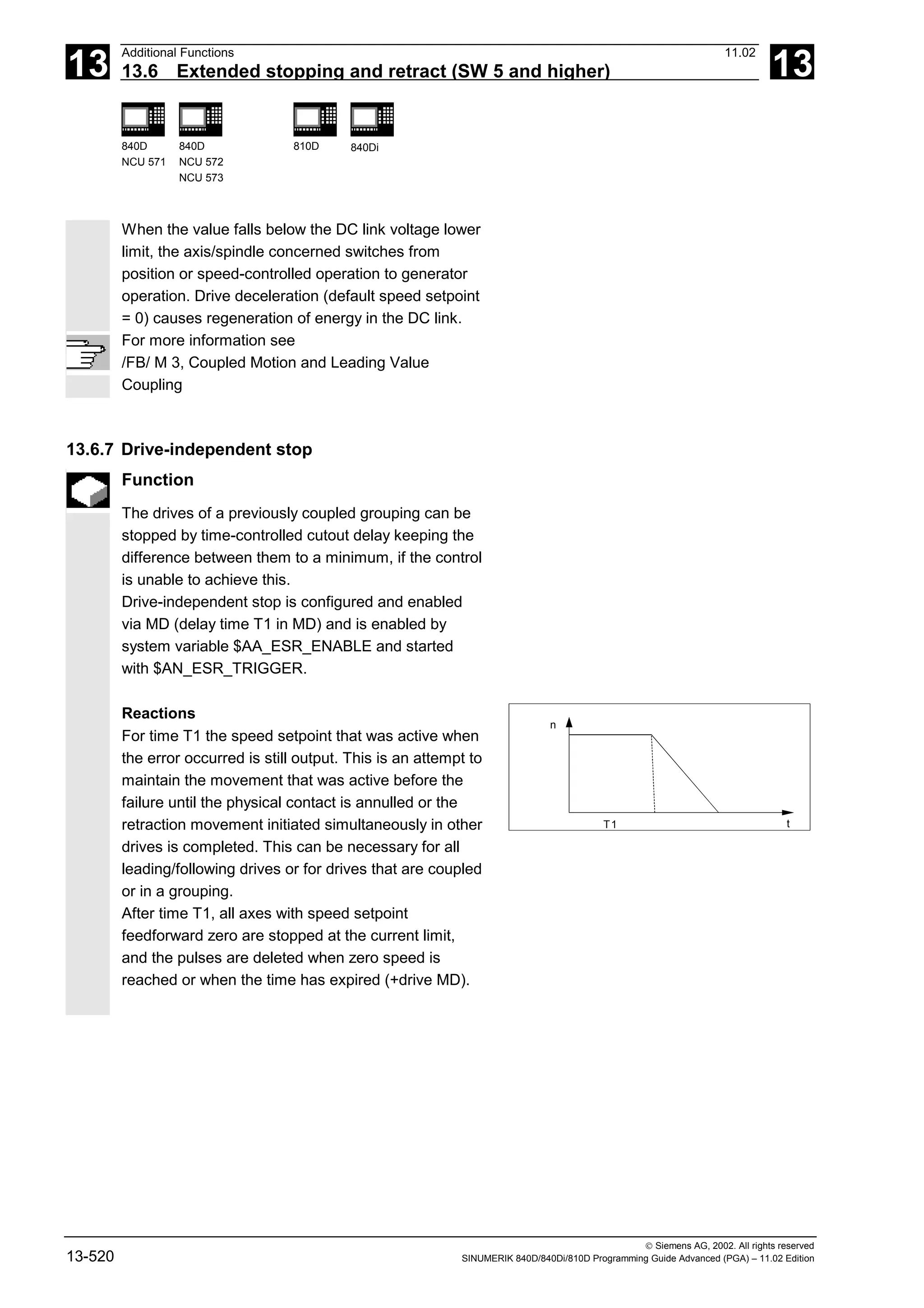
![13
11.02 Additional Functions
13.6 Extended stopping and retract (SW 5 and higher) 13
840D
NCU 571
840D
NCU 572
NCU 573
810D 840Di
Siemens AG, 2002. All rights reserved
SINUMERIK 840D/840Di/810D Programming Guide Advanced (PGA) – 11.02 Edition 13-521
13.6.8 Drive-independent retract
Function
Axes with digital 611D drives can (if configured and
released) also execute a retraction movement
independently
• at control failure (sign-of-life detection)
• if the DC link voltage falls below a warning
threshold
• if triggered by the system variable
$AN_ESR_TRIGGER.
The retraction movement is performed
independently by drive 611D.
Once the retraction phase is initiated, the drive
independently maintains its enables at the values
that were previously valid.
For more information see
/FB/ M 3, Coupled Motion and Leading Value
Coupling
13.6.9 Example: Using the drive-independent reaction
Example configuration
• Axis A is to operate as generator drive,
• axis X is to retract by 10 mm at maximum speed
in event of an error and
• axes Y and Z are to stop with a time delay of
100 ms, such that the retraction axis has time to
cancel the mechanical coupling.
Sequence
1. Activate options "Ext. Stop and retract" and
"Mode-independent actions" (includes "Static
synchronized actions IDS ...)".
2. Function assignment:
$MA_ESR_REACTION[X]=11,
$MA_ESR_REACTION[Y]=12,
$MA_ESR_REACTION[Z]=12,
$MA_ESR_REACTION[A]=10;](https://image.slidesharecdn.com/fadaladvancedprogrammingmanual-220505063253/75/Fadal-Advanced-Programming-Manual-pdf-521-2048.jpg)
![13
Additional Functions 11.02
13.7 Link communication (SW 5.2 and higher) 13
840D
NCU 571
840D
NCU 572
NCU 573
810D 840Di
Siemens AG, 2002. All rights reserved
13-522 SINUMERIK 840D/840Di/810D Programming Guide Advanced (PGA) – 11.02 Edition
3. Drive configuration:
MD 1639 RETRACT_SPEED[X] =400000H in pos. direction (max. speed),
=FFC00000H in neg. direction,
MD 1638 RETRACT_TIME[X] =10ms (retract time),
MD 1637 GEN_STOP_DELAY[Y] =100ms,
MD 1637 GEN_STOP_DELAY[Z] =100ms,
MD 1635 GEN_AXIS_MIN_SPEED[A] =Generator min. speed (rpm).
4. Function enable (from parts program or
synchronized actions): $AA_ESR_ENABLE[X]=1,
$AA_ESR_ENABLE[Y]=1,
$AA_ESR_ENABLE[Z]=1,
$AA_ESR_ENABLE[A]=1
5. Get the generator operation to "momentum" speed
(e.g. in spindle operation M03 S1000)
6. Formulate trigger condition as static synchronized action(s), e.g.:
• dependent on intervention of the generator axis:
IDS=01 WHENEVER $AA_ESR_STAT[A]>0 DO
$AN_ESR_TRIGGER=1
• and/or dependent on alarms that trigger follow-up mode
(bit13=2000H):
IDS=02 WHENEVER ($AC_ALARM_STAT B_AND
'H2000')>0
DO $AN_ESR_TRIGGER=1
• and also dependent on EU synchronized operation (if, for
example, Y is defined as EU following axis and if the max.
allowed deviation of synchronized operation shall be
100 µml):
IDS=03 WHENEVER ABS($VA_EG_SYNCDIFF[Y])>0.1
DO $AN_ESR_TRIGGER=1
13.7 Link communication (SW 5.2 and higher)
Function
The NCU link, which connects several NCU units
from an installation, is used in configurations with a
distributed system design. When there is a high
demand for axes and channels, e.g. with revolving
machines and multi-spindle machines, computing
capacity, configuration options and memory areas
can reach their limits when only one NCU is used.](https://image.slidesharecdn.com/fadaladvancedprogrammingmanual-220505063253/75/Fadal-Advanced-Programming-Manual-pdf-522-2048.jpg)

![13
Additional Functions 11.02
13.7 Link communication (SW 5.2 and higher) 13
840D
NCU 571
840D
NCU 572
NCU 573
810D 840Di
Siemens AG, 2002. All rights reserved
13-524 SINUMERIK 840D/840Di/810D Programming Guide Advanced (PGA) – 11.02 Edition
Link variables are global system data that can be
addressed by the connected NCUs as system
variables. The
- contents of these variables,
- their data type,
- use, and
- position (access index) in the link memory
are defined by the user (in this case generally the
machine manufacturer).
Link variables are stored in the link memory.
After power-up, the link memory is initialized with 0.
The following link variables can be addressed within
the link memory:
• INT $A_DLB[i] ; data byte (8 bits)
• INT $A_DLW[i] ; data word (16 bits)
• INT $A_DLD[i] ; double data word (32 bits)
• REAL $A_DLR[i] ; real data (64 bits)
According to the type in question, 1, 2, 4 or 8 bytes
are addressed when the link variables are
written/read.
Index i defines the start of the respective variable in
relation to the start of the configured link memory.
The index is counted from 0 up.
Value ranges
The different data types have the following value
ranges:
BYTE: 0 to 255
WORD: –32768 to 32767
DWORD: –2147483648 to 2147483647
REAL: –4.19e-308 to 4.19e-307
The various NCU applications sharing access to the
link memory at the same time must use the link
memory in a uniform manner. When the process is
completely separate in time, the link memory can be
occupied differently.](https://image.slidesharecdn.com/fadaladvancedprogrammingmanual-220505063253/75/Fadal-Advanced-Programming-Manual-pdf-524-2048.jpg)
![13
11.02 Additional Functions
13.7 Link communication (SW 5.2 and higher) 13
840D
NCU 571
840D
NCU 572
NCU 573
810D 840Di
Siemens AG, 2002. All rights reserved
SINUMERIK 840D/840Di/810D Programming Guide Advanced (PGA) – 11.02 Edition 13-525
Warning
A link variable write process is only then completed
when the written information is also available to all
the other NCUs. Approximately two interpolation
cycles are necessary for this process. Local writing
to the link memory is delayed by the same time for
purposes of consistency.
For more information, please refer to the Description
of Functions B3 (SW 5)
Programming example
$A_DLB[5]=21 The 5th byte in the shared link memory is
assigned value 21.](https://image.slidesharecdn.com/fadaladvancedprogrammingmanual-220505063253/75/Fadal-Advanced-Programming-Manual-pdf-525-2048.jpg)
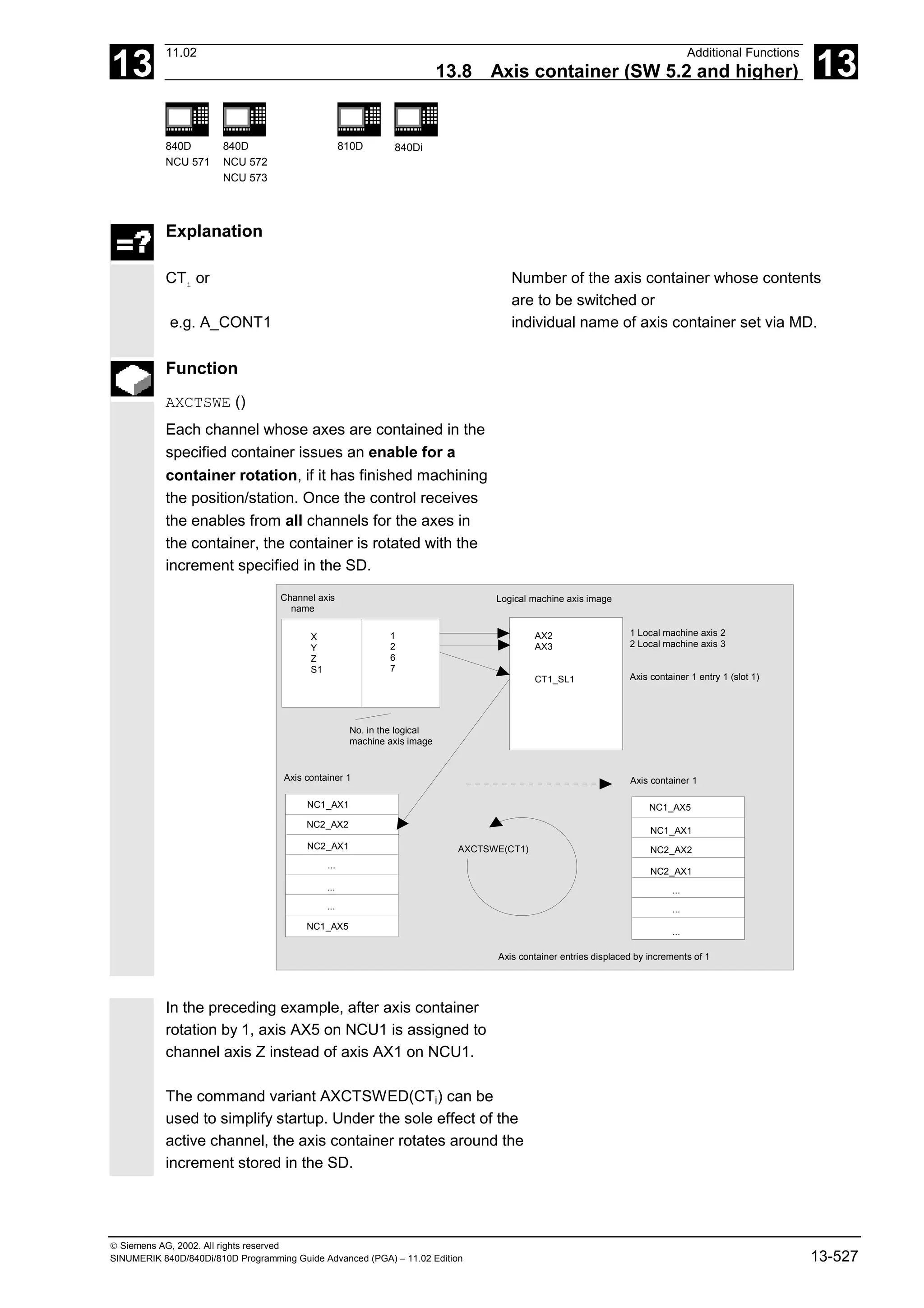
![13
11.02 Additional Functions
13.9 Program execution time/Workpiece counter (SW 5.2 and higher) 13
840D
NCU 571
840D
NCU 572
NCU 573
810D 840Di
Siemens AG, 2002. All rights reserved
SINUMERIK 840D/840Di/810D Programming Guide Advanced (PGA) – 11.02 Edition 13-531
Programming example
1. Activate workpiece counter $AC_REQUIRED_PARTS:
$MC_PART_COUNTER='H3' $AC_REQUIRED_PARTS is active, display
alarm on $AC_REQUIRED_PARTS ==
$AC_SPECIAL_PARTS
2. Activate workpiece counter $AC_TOTAL_PARTS:
$MC_PART_COUNTER='H10'
$MC_PART_COUNTER_MCODE[0]=80
$AC_TOTAL_PARTS is active, the counter is
incremented by 1 on each M02,
$MC_PART_COUNTER_MCODE[0] is
irrelevant
3. Activate workpiece counter $AC_ACTUAL_PARTS:
$MC_PART_COUNTER='H300'
$MC_PART_COUNTER_MCODE[1]=17
$AC_TOTAL_PARTS is active, the counter is
incremented by 1 on each M17
4. Activate workpiece counter $AC_SPECIAL_PARTS:
$MC_PART_COUNTER='H3000'
$MC_PART_COUNTER_MCODE[2]=77
$AC_SPECIAL_PARTS is active, the counter
is incremented by 1 on each M77
5. Deactivate workpiece counter $AC_ACTUAL_PARTS:
$MC_PART_COUNTER='H200'
$MC_PART_COUNTER_MCODE[1]=50
$AC_TOTAL_PARTS is not active, rest
irrelevant
6. Activate all counters, examples 1-4:
$MC_PART_COUNTER ='H3313'
$MC_PART_COUNTER_MCODE[0] =80
$MC_PART_COUNTER_MCODE[1] =17
$MC_PART_COUNTER_MCODE[2] =77
$AC_REQUIRED_PARTS is active
Display alarm on $AC_REQUIRED_PARTS
== $AC_SPECIAL_PARTS
$AC_TOTAL_PARTS is active, the counter is
incremented by 1 on each M02
$MC_PART_COUNTER_MCODE[0] is
irrelevant
$AC_ACTUAL_PARTS is active, the counter
is incremented by 1 on each M17
$AC_SPECIAL_PARTS is active, the counter
is incremented by 1 on each M77](https://image.slidesharecdn.com/fadaladvancedprogrammingmanual-220505063253/75/Fadal-Advanced-Programming-Manual-pdf-531-2048.jpg)
![13
Additional Functions 11.02
13.11 Influencing the motion control 13
840D
NCU 571
840D
NCU 572
NCU 573
810D 840Di
Siemens AG, 2002. All rights reserved
13-534 SINUMERIK 840D/840Di/810D Programming Guide Advanced (PGA) – 11.02 Edition
13.11 Influencing the motion control
13.11.1 Percentage jerk correction: JERKLIM
Programming
JERKLIM[axis]= ...
Explanation of the command
JERKLIM
Percentage change for the greatest permissible jerk relative to
the value set in the machine data for the axis
Axis
Machine axis whose jerk limit has to adapted
Function
In critical program sections, it may be necessary to
limit the jerk to below maximum value, for example,
to reduce mechanical stress. The acceleration mode
SOFT must be active.
The function only effects path axes.
Sequence
In the AUTOMATIC modes, the jerk limit is limited to
the percentage of the jerk limit stored in the machine
data.
Example: N60 JERKLIM[X]=75
Meaning: The axis carriage in the X direction must
be accelerated/decelerated with only 75% of the jerk
permissible for the axis.
Value range: 1 ... 200
100 corresponds to: no effect on jerk.
100 is applied after RESET and parts program start.](https://image.slidesharecdn.com/fadaladvancedprogrammingmanual-220505063253/75/Fadal-Advanced-Programming-Manual-pdf-534-2048.jpg)
![13
11.02 Additional Functions
13.11 Influencing the motion control 13
840D
NCU 571
840D
NCU 572
NCU 573
810D 840Di
Siemens AG, 2002. All rights reserved
SINUMERIK 840D/840Di/810D Programming Guide Advanced (PGA) – 11.02 Edition 13-535
Additional notes
A further example will follow at the end of the next
subsection.
13.11.2 Percentage velocity correction: VELOLIM
Programming
VELOLIM[axis]= ...
Explanation of the command
VELOLIM
Percentage change for the greatest permissible velocity relative
to the value set in the machine data for the axis
Axis
Machine axis whose velocity limit has to adapted
Function
In critical program sections, it may be necessary to
limit the velocity to below maximum values, for
example, to reduce mechanical stress or enhance
finish. The function only effects path and positioning
axes.
Sequence
In the AUTOMATIC modes, the velocity limit is
limited to the percentage of the velocity limit stored
in the machine data.
Example: N70 VELOLIM[X]=80
Meaning: The axis carriage in the X direction must
travel at only 80% of the velocity permissible for the
axis.](https://image.slidesharecdn.com/fadaladvancedprogrammingmanual-220505063253/75/Fadal-Advanced-Programming-Manual-pdf-535-2048.jpg)
![13
Additional Functions 11.02
13.12 Master/slave grouping 13
840D
NCU 571
840D
NCU 572
NCU 573
810D 840Di
Siemens AG, 2002. All rights reserved
13-536 SINUMERIK 840D/840Di/810D Programming Guide Advanced (PGA) – 11.02 Edition
Value range: 1 ... 100
100 corresponds to: no effect on velocity.
100 is applied after RESET and parts program start.
Programming example
N1000 G0 X0 Y0 F10000 SOFT G64
N1100 G1 X20 RNDM=5 ACC[X]=20
ACC[Y]=30
N1200 G1 Y20 VELOLIM[X]=5
JERKLIM[Y]=200
N1300 G1 X0 JERKLIM[X]=2
N1400 G1 Y0
M30
13.12 Master/slave grouping
Programming:
MASLDEF(Slv1, Slv2, ..., master axis) For dynamic configuration
(SW 6.4 and higher)
MASLDEL(Slv1, Slv2, ..., ) For dynamic configuration
(SW 6.4 and higher)
MASLON(Slv1, Slv2, ..., )
MASLOF(Slv1, Slv2, ..., )
MASLOFS(Slv1, Slv2, ..., ) (SW 6.4 and higher)
Explanation of the parameters
Slv1, Slv2, ... Slave axes led by a master axis
Master axis Axis leading slave axes defined in a
master/slave grouping](https://image.slidesharecdn.com/fadaladvancedprogrammingmanual-220505063253/75/Fadal-Advanced-Programming-Manual-pdf-536-2048.jpg)
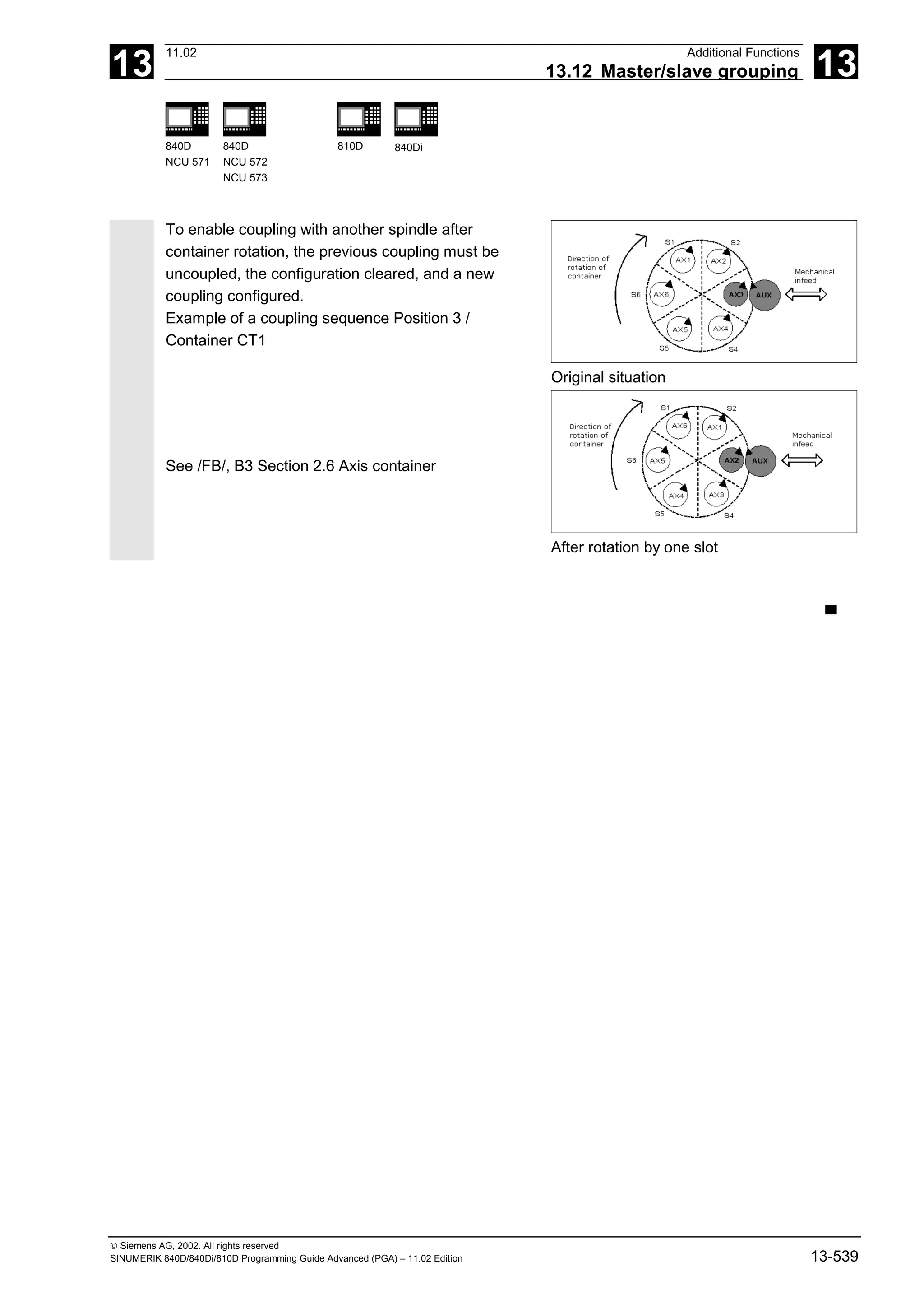
![14
11.02 User Stock Removal Programs
14.2 Contour preparation: CONTPRON 14
840D
NCU 571
840D
NCU 572
NCU 573
810D 840Di
Siemens AG, 2002. All rights reserved
SINUMERIK 840D/840Di/810D Programming Guide Advanced (PGA) – 11.02 Edition 14-545
Programming example 1
Create a contour table with
• name KTAB,
• up to 30 contour elements (circles, straight lines),
• a variable for the number of relief cut elements,
• a variable for error messages
150
(20,150)
100
50
50 100 150
Z
X
(30,110)
(30,65)
(70,50)
(85,40)
(90,30)
(90,0)
(45,50)
NC parts program
N10 DEF REAL KTAB[30,11] Contour table named KTAB and, for
example, a maximum of 30 contour
elements
Parameter value 11 is a fixed size
N20 DEF INT ANZHINT Variable for number of relief cut elements
with name ANZHINT
N30 DEF INT ERROR Variable for acknowledgment
0 = no error, 1 = error
N40 G18
N50 CONTPRON (KTAB,"G",ANZHINT) Contour preparation call
N60 G1 X150 Z20
N70 X110 Z30
N80 X50 RND=15
N90 Z70
N100 X40 Z85
N110 X30 Z90
N120 X0
N60 to N120 contour description
N130 EXECUTE(ERROR) Terminate filling of contour table, switch to
normal program execution
N140 … Continue processing table](https://image.slidesharecdn.com/fadaladvancedprogrammingmanual-220505063253/75/Fadal-Advanced-Programming-Manual-pdf-545-2048.jpg)
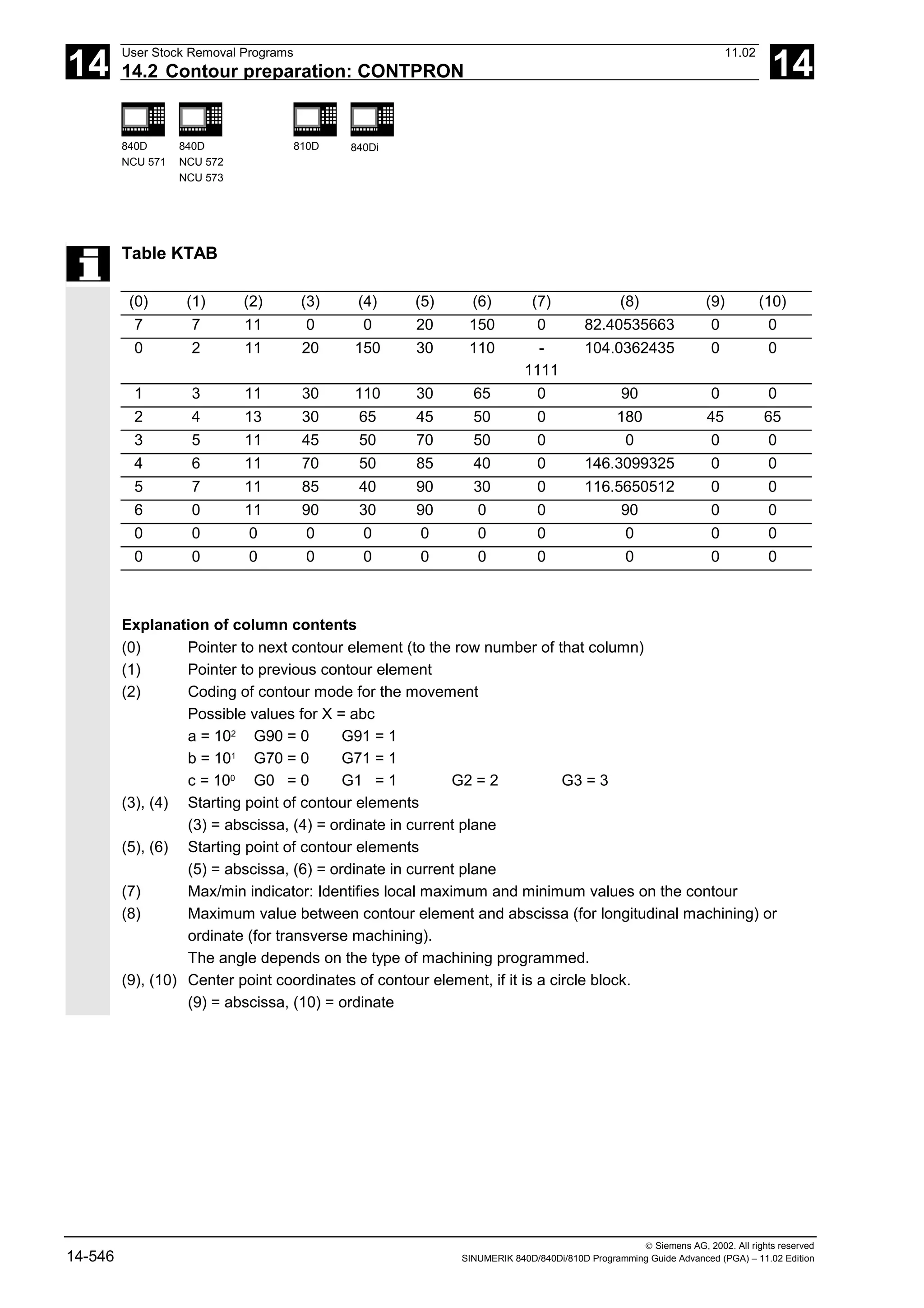
![14
11.02 User Stock Removal Programs
14.2 Contour preparation: CONTPRON 14
840D
NCU 571
840D
NCU 572
NCU 573
810D 840Di
Siemens AG, 2002. All rights reserved
SINUMERIK 840D/840Di/810D Programming Guide Advanced (PGA) – 11.02 Edition 14-547
Programming example 2
Create a contour table with
• name KTAB,
• up to 92 contour elements (circles, straight lines),
• mode: Longitudinal turning, external machining
• preparation forwards and backwards.
(100,100)
-50 50 100
Z
(-30,80)
(-30,30)
(20,20)
(20,45)
(0,45)
(-15,30)
150
100
50
X
(-40,80)
NC parts program
N10 DEF REAL KTAB[92,11] Contour table named KTAB and, for
example, a maximum of 92 contour
elements
Parameter value 11 is a fixed size
N20 CHAR BT="L" Mode for CONTPRON:
Longitudinal turning, external machining
N30 DEF INT HE=0 Number of relief cut elements=0
N40 DEF INT MODE=1 Preparation forwards and backwards
N50 DEF INT ERR=0 Error checkback message
...
N100 G18 X100 Z100 F1000
N105 CONTPRON (KTAB, BT, HE, MODE) Contour preparation call
N110 G1 G90 Z20 X20
N120 X45
N130 Z0
N140 G2 Z-15 X30 K=AC(-15) I=AC(45)
N150 G1 Z-30
N160 X80
N170 Z-40
N180 EXECUTE(ERR) Terminate filling of contour table, switch to
normal program execution
...](https://image.slidesharecdn.com/fadaladvancedprogrammingmanual-220505063253/75/Fadal-Advanced-Programming-Manual-pdf-547-2048.jpg)
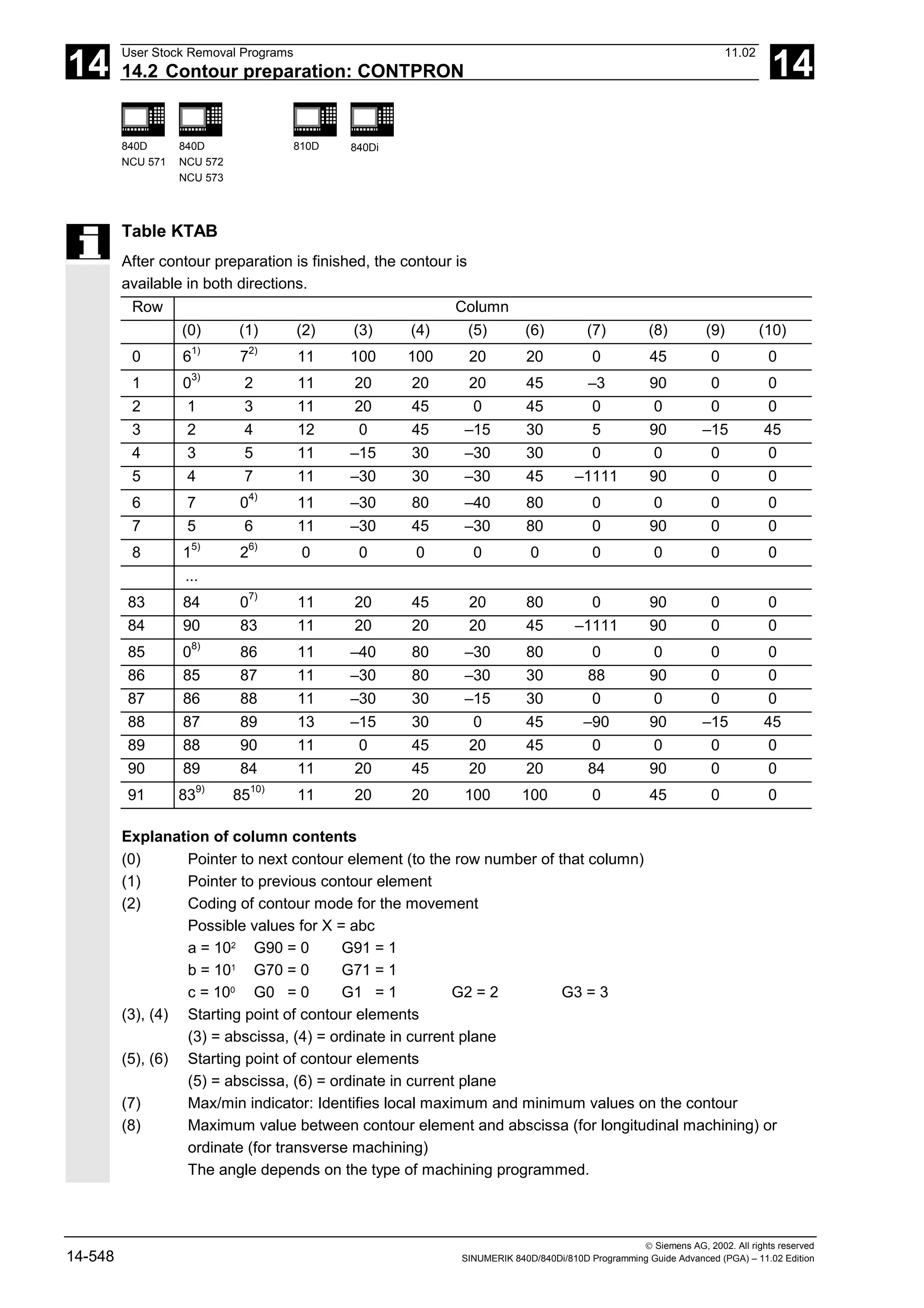
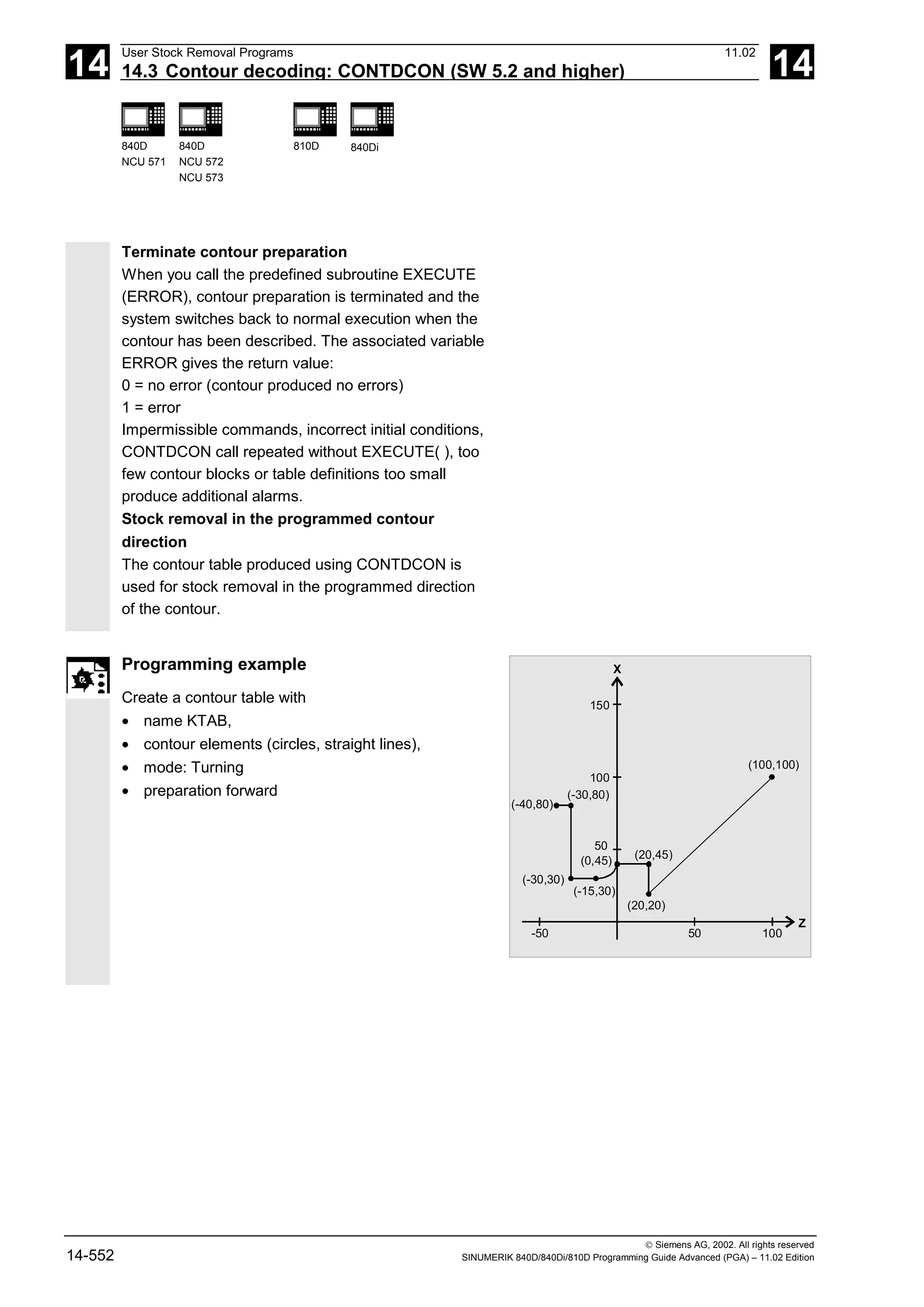
![14
11.02 User Stock Removal Programs
14.3 Contour decoding: CONTDCON (SW 5.2 and higher) 14
840D
NCU 571
840D
NCU 572
NCU 573
810D 840Di
Siemens AG, 2002. All rights reserved
SINUMERIK 840D/840Di/810D Programming Guide Advanced (PGA) – 11.02 Edition 14-553
NC parts program
N10 DEF REAL KTAB[9,6] Contour table with name KTAB and 9 table
cells. These allow 8 contour sets.
Parameter value 6 (column number in table)
is fixed.
N20 DEF INT MODE = 0 Default value 0: Only in programmed
contour direction. Value 1 is not permitted.
N30 DEF INT ERROR = 0 Error checkback message
...
N100 G18 G64 G90 G94 G710
N101 G1 Z100 X100 F1000
N105 CONTDCON (KTAB, MODE) Call contour decoding
MODE may be omitted (see above)
N110 G1 Z20 X20 F200
N120 G9 X45 F300
N130 Z0 F400
Contour description
N140 G2 Z-15 X30 K=AC(-15) I=AC(45)F100
N150 G64 Z-30 F600
N160 X80 F700
N170 Z-40 F800
N180 EXECUTE(ERROR) Terminate filling of contour table, switch to
normal program execution
...
Column index 0 1 2 3 4 5
Line index Contour
mode
End point
abscissa
End point
ordinate
Center point
Abscissa
Center point
ordinate
Feed
0 30 100 100 0 0 7
1 11031 20 20 0 0 200
2 111031 20 45 0 0 300
3 11031 0 45 0 0 400
4 11032 –15 30 –15 45 100
5 11031 –30 30 0 0 600
6 11031 –30 80 0 0 700
7 11031 –40 80 0 0 800
8 0 0 0 0 0 0](https://image.slidesharecdn.com/fadaladvancedprogrammingmanual-220505063253/75/Fadal-Advanced-Programming-Manual-pdf-553-2048.jpg)
![14
User Stock Removal Programs 11.02
14.4 Intersection of two contour elements: INTERSEC 14
840D
NCU 571
840D
NCU 572
NCU 573
810D 840Di
Siemens AG, 2002. All rights reserved
14-554 SINUMERIK 840D/840Di/810D Programming Guide Advanced (PGA) – 11.02 Edition
Explanation of column contents
Line 0: Coding for starting point:
Column 0:
10
0
(ones): G0 = 0
10
1
(tens): G70 = 0, G71 = 1, G700 = 2, G710 = 3
Column 1: starting point of abscissa
Column 2: starting point of ordinate
Column 3-4: 0
Column 5 Line index of last contour piece in the table
Lines 1-n: Entries for contour pieces:
Column 0:
10
0
(ones): G0 = 0, G1 = 1, G2 = 2, G3 = 3
10
1
(tens): G70 = 0, G71 = 1, G700 = 2, G710 = 3
10
2
(hundreds): G90 = 0, G91 = 1
10
3
(thousands): G93 = 0, G94 = 1, G95 = 2, G96 = 3
10
4
(ten thousands): G60 = 0, G44 = 1, G641 = 2, G642 = 3
10
5
(hundred thousands): G9 = 1
Column 1: End point abscissa
Column 2: End point ordinate
Column 3: Center point Abscissa for circular interpolation
Column 4: Center point ordinate for circular interpolation
Column 5: Feedrate
14.4 Intersection of two contour elements: INTERSEC
Programming
VARIB=INTERSEC (TABNAME1[n1], TABNAME2[n2], TABNAME3)
Explanation of the parameters
VARIB Variable for status TRUE: Intersection found
FALSE: No intersection found
TABNAME1[n1] Table name and n1st contour element of the first table
TABNAME2[n2] Table name and n2nd contour element of the second table
TABNAME3 Table name for the intersection coordinates in the active plane G17–G19](https://image.slidesharecdn.com/fadaladvancedprogrammingmanual-220505063253/75/Fadal-Advanced-Programming-Manual-pdf-554-2048.jpg)
![14
11.02 User Stock Removal Programs
14.4 Intersection of two contour elements: INTERSEC 14
840D
NCU 571
840D
NCU 572
NCU 573
810D 840Di
Siemens AG, 2002. All rights reserved
SINUMERIK 840D/840Di/810D Programming Guide Advanced (PGA) – 11.02 Edition 14-555
Function
INTERSEC calculates the intersection of two
normalized contour elements from the contour table
generated with CONTPRON. The indicated status
specifies whether or not an intersection exists (TRUE =
intersection, FALSE = no intersection).
Additional notes
Please note that variables must be defined before
they are used.
Programming example
Calculate the intersection of contour element 3 in
table KTAB1 and contour element 7 in table KTAB2.
The intersection coordinates in the active plane are
stored in CUT (1st element = abscissa, 2nd element
= ordinate).
If no intersection exists, the program jumps to
NOCUT (no intersection found).
DEF REAL KTAB1 [12, 11] Contour table 1
DEF REAL KTAB2 [10, 11] Contour table 2
DEF REAL CUT [2] Intersection table
DEF BOOL ISPOINT Variable for status
…
N10 ISPOINT=INTERSEC (KTAB1[3],KTAB2[7],CUT)
Call intersection of contour elements
N20 IF ISPOINT==FALSE GOTOF NOCUT Jump to NOCUT
…](https://image.slidesharecdn.com/fadaladvancedprogrammingmanual-220505063253/75/Fadal-Advanced-Programming-Manual-pdf-555-2048.jpg)
![14
User Stock Removal Programs 11.02
14.5 Traversing a contour element from the table: EXECTAB 14
840D
NCU 571
840D
NCU 572
NCU 573
810D 840Di
Siemens AG, 2002. All rights reserved
14-556 SINUMERIK 840D/840Di/810D Programming Guide Advanced (PGA) – 11.02 Edition
14.5 Traversing a contour element from the table: EXECTAB
Programming
EXECTAB (TABNAME[n])
Explanation of the parameter
TABNAME[n] Name of table with number n of the element
Function
You can use command EXECTAB to traverse
contour elements block by block in a table
generated, for example, with the CONTPRON
command.
Programming example
The contour elements stored in Table KTAB are
traversed non-modally by means of subroutine
EXECTAB. Elements 0 to 2 are passed in
consecutive calls.
N10 EXECTAB (KTAB[0]) Traverse element 0 of table KTAB
N20 EXECTAB (KTAB[1]) Traverse element 1 of table KTAB
N30 EXECTAB (KTAB[2]) Traverse element 2 of table KTAB](https://image.slidesharecdn.com/fadaladvancedprogrammingmanual-220505063253/75/Fadal-Advanced-Programming-Manual-pdf-556-2048.jpg)
![14
11.02 User Stock Removal Programs
14.6 Calculate circle data: CALCDAT 14
840D
NCU 571
840D
NCU 572
NCU 573
810D 840Di
Siemens AG, 2002. All rights reserved
SINUMERIK 840D/840Di/810D Programming Guide Advanced (PGA) – 11.02 Edition 14-557
14.6 Calculate circle data: CALCDAT
Programming
VARIB = CALCDAT(PT[n,2],NO,RES)
Explanation of the parameters
VARIB Variable for status
TRUE = circle, FALSE = no circle
PT[n,2] Points for calculation
n = number of points (3 or 4); 2 = point coordinates
NO. Number of points used for calculation: 3 or 4
RES[3] Variable for result: specification of circle center point coordinates and
radius;
0 = abscissa, 1 = ordinate of circle center point; 2 = radius
Function
Calculation of radius and circle center point coordinates
from three or four known circle points.
The specified points must be different.
Where 4 points do not lie directly on the circle an
average value is taken for the circle center point and
the radius.](https://image.slidesharecdn.com/fadaladvancedprogrammingmanual-220505063253/75/Fadal-Advanced-Programming-Manual-pdf-557-2048.jpg)
![14
User Stock Removal Programs 11.02
14.6 Calculate circle data: CALCDAT 14
840D
NCU 571
840D
NCU 572
NCU 573
810D 840Di
Siemens AG, 2002. All rights reserved
14-558 SINUMERIK 840D/840Di/810D Programming Guide Advanced (PGA) – 11.02 Edition
Programming example
The program determines whether the three points lie
along the arc of a circle. 60
50
40
30
20
10
60
50
40
30
20
ERG [1]
ERG [0]
10
Y
(20,50)
(50,40)
(65,20)
70
X
E
R
G
[
2
]
N10 DEF REAL
PT[3,2]=(20,50,50,40,65,20)
Point definition
N20 DEF REAL RES[3] Result
N30 DEF BOOL STATUS Variable for status
N40 STATUS = CALCDAT(PT,3,RES) Call calculated circle data
N50 IF STATUS == FALSE GOTOF ERROR Jump to error
■](https://image.slidesharecdn.com/fadaladvancedprogrammingmanual-220505063253/75/Fadal-Advanced-Programming-Manual-pdf-558-2048.jpg)
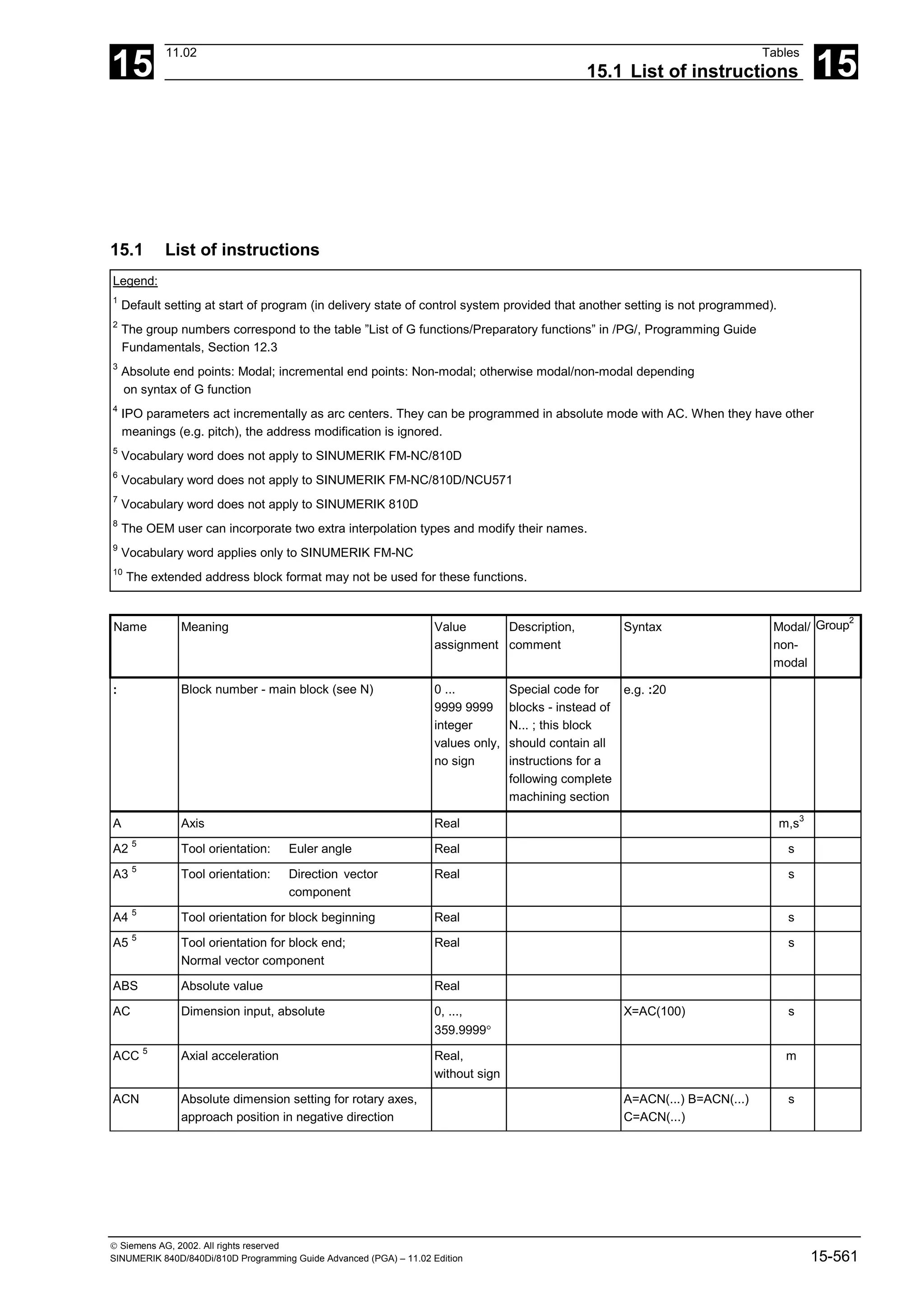
![15
Tables 11.02
15.1 List of instructions 15
Siemens AG, 2002. All rights reserved
15-562 SINUMERIK 840D/840Di/810D Programming Guide Advanced (PGA) – 11.02 Edition
ACP Absolute dimension setting for rotary axes,
approach position in positive direction
A=ACP(...) B=ACP(...)
C=ACP(...)
s
ACOS Arc cosine (trigon. function) Real
ADIS Resurfacing distance for path functions G1,
G2, G3, ...
Real, without
sign
m
ADISPOS Resurfacing distance for rapid traverse G0 Real, without
sign
m
ADISPOSA Size of the tolerance window for IPOBRKA Integer, real, ADISPOSA=.. or
ADISPOSA(<axis>[,REAL])
m
ALF Angle lift fast Integer,
without sign
m
AMIRROR Programmable mirroring (additive mirror) AMIRROR X0 Y0 Z0
; separate block
s 3
AND Logical AND
ANG Contour definition angle Real
AP Polar angle (Angle Polar) 0, ..., ± 360° m,s3
APR Read/display access protection
(access protection read)
Integer,
without sign
APW Write access protection
(access protection write)
Integer,
without sign
AR Aperture angle (angle circular) 0, ..., 360° m,s3
AROT Programmable rotation
(additive rotation)
Rotation
around 1st
geom. axis:
-180o
.. 180°
2nd geom.
axis:
-89.999°
.. 90°
3rd geo. axis:
-180° .. 180°
AROT X... Y... Z...
;separate
AROT RPL= block
s 3
AROTS programmable frame rotations with solid angles (additive
rotation)
AROT X... Y...
AROT Z... X...
AROT Y... Z... ;own
AROT RPL= block
s 3
AS Macro definition String
ASCALE Programmable scaling (additive scale) ASCALE X... Y... Z...
; separate block
s 3
ASIN Arc sine (trigon. function) Real
ASPLINE Akima spline m 1
ATAN2 Arc tangent 2 Real
ATRANS Additive programmable offset
(additive translation)
ATRANS X... Y... Z...
; separate block
s 3
AX Integer without sign Real m,s3](https://image.slidesharecdn.com/fadaladvancedprogrammingmanual-220505063253/75/Fadal-Advanced-Programming-Manual-pdf-562-2048.jpg)
![15
11.02 Tables
15.1 List of instructions 15
Siemens AG, 2002. All rights reserved
SINUMERIK 840D/840Di/810D Programming Guide Advanced (PGA) – 11.02 Edition 15-563
AXCSWAP Switch container axis AXCSWAP(CTn,CTn+1,...) 25
AXIS Data type: Axis name Name of file can be
added
AXNAME Converts the input string to an axis name
(get axname)
String An alarm is
generated if the
input string does
not contain a valid
axis name
AXSTRING Up to SW 5, axis identifier is converted to
string (get axis as string)
With SW 6 and higher, the spindle number
converts the string (get string)
Up to SW 5
AXIS
from SW 6
string
Name of file can
be added
AXSTRING( SPI(n) )
From SW 6
AXSTRING[ SPI(n) ]
B Axis Real m,s3
B_AND Bit AND
B_NOT Bit negation
B_OR Bit OR
B_XOR Bit exclusive OR
B2 5
Tool orientation:
Euler angle
Real s
B3 5
Tool orientation:
Direction vector component
Real s
B4 5
Tool orientation for block beginning Real s
B5 5
Tool orientation for block end;
Normal vector component
Real s
BAUTO Definition of first spline segment by means of following 3
points (begin not a knot)
m 19
BLSYNC Processing of interrupt routine is only to start with the
next block change
BNAT 1
Natural transition to first spline block
(begin natural)
m 19
BOOL Data type: Boolean value TRUE / FALSE or 0 / 1
BRISK 1
Brisk path acceleration m 21
BRISKA Activate brisk axis acceleration for the programmed axes
BSPLINE B spline m 1
BTAN Tangential transition to first spline block
(begin tangential)
m 19
C Axis Real m,s3
C2 5
Tool orientation: Euler angle Real s
C3 5
Tool orientation:
Direction vector component
Real s
C4 5
Tool orientation for block beginning Real s](https://image.slidesharecdn.com/fadaladvancedprogrammingmanual-220505063253/75/Fadal-Advanced-Programming-Manual-pdf-563-2048.jpg)
![15
Tables 11.02
15.1 List of instructions 15
Siemens AG, 2002. All rights reserved
15-564 SINUMERIK 840D/840Di/810D Programming Guide Advanced (PGA) – 11.02 Edition
C5 5
Tool orientation for block end;
Normal vector component
Real s
CAC Absolute approach of position
(coded position: absolute coordinate)
Coded value is
table index; table
value is
approached
CACN Absolute approach in negative direction of value stored in
table.
(coded position absolute negative)
Permissible for
programming rotary
axes as positioning
axes
CACP Absolute approach in positive direction of value stored in
table.
(coded position absolute positive)
CALCDAT Calculate radius and center point or circle
from 3 or 4 points
(calculate circle data)
VAR Real
[3]
The points must be
different.
CALL Indirect subroutine call CALL PROGVAR
CALLPATH Programmable search path for subprogram calls A path can be
programmed to the
existing NCK file
system with
CALLPATH.
CALLPATH(/_N_WKS
_DIR/
_N_MYWPD/subprogram
_ID_SPF)
CANCEL Cancel modal synchronized action INT Cancel with
specified ID.
Without parameter:
All modal
synchronized
actions are
deselected.
CASE Conditional program branch
CDC Direct approach of position
(coded position: direct coordinate)
See CAC
CDOF 1
Collision detection OFF m 23
CDON Collision detection ON m 23
CDOF2 Collision detection OFF For CUT3DC only m 23
CFC 1
Constant feed on contour m 16
CFIN Constant feed at internal radius only,
not at external radius
m 16
CFTCP Constant feed at tool center point (center-point path)
(constant feed in tool-center-point)
m 16
CHAN Specify validity range for data once per channel](https://image.slidesharecdn.com/fadaladvancedprogrammingmanual-220505063253/75/Fadal-Advanced-Programming-Manual-pdf-564-2048.jpg)
![15
11.02 Tables
15.1 List of instructions 15
Siemens AG, 2002. All rights reserved
SINUMERIK 840D/840Di/810D Programming Guide Advanced (PGA) – 11.02 Edition 15-565
CHANDATA Set channel number for channel data
access
INT Only permissible in
the initialization
module
CHAR Data type: ASCII character 0, ..., 255
CHF
SW 3.5
and higher
CHR
Chamfer; value = length of chamfer in
direction of movement (chamfer)
Chamfer; value = length of chamfer
Real,
without sign
s
CHKDNO D number check
CIC Incremental approach of position
(coded position: incremental coordinate)
See CAC
CIP Circular interpolation through intermediate points CIP X... Y... Z...
I1=... J1=... K1=...
m 1
CLEARM Reset one/several markers for channel
coordination
INT,
1 - n
Does not influence
machining in own
channel
CLGOF Const. workpiece speed for centerless grinding OFF
CLGON Const. workpiece speed for centerless grinding ON
CLRINT Deselect interrupt: INT Parameter:
Interrupt number
CMIRROR Mirror on a coordinate axis FRAME
COARSEA Motion end when "Exact stop coarse" reached COARSEA=.. or
COARSEA[n]=..
m
COMPOF
1,6
Compressor OFF m 30
COMPON
6
Compressor ON m 30
COMPCURV Compressor ON constant curve polynomials m 30
COMPCAD Compressor ON optimized surface finish m 30
CONTPRON Activate contour preparation (contour preparation ON) m 49
COS Cosine (trigon. function) Real
COUPDEF Definition ELG group / synchronous spindle
group
(couple definition)
String Block change (soft-
ware) response:
NOC: no software
control,
FINE/COARSE:
software on ”Syn-
chronization fine /
coarse”,
IPOSTOP: software
on setpoint-depen-
dent termination of
overlaid movement
COUPDEL Delete ELG group (couple delete)
COUPOF ELG group / synchronous spindle pair OFF (couple OFF)
COUPON ELG group / synchronous spindle pair ON (couple ON)](https://image.slidesharecdn.com/fadaladvancedprogrammingmanual-220505063253/75/Fadal-Advanced-Programming-Manual-pdf-565-2048.jpg)
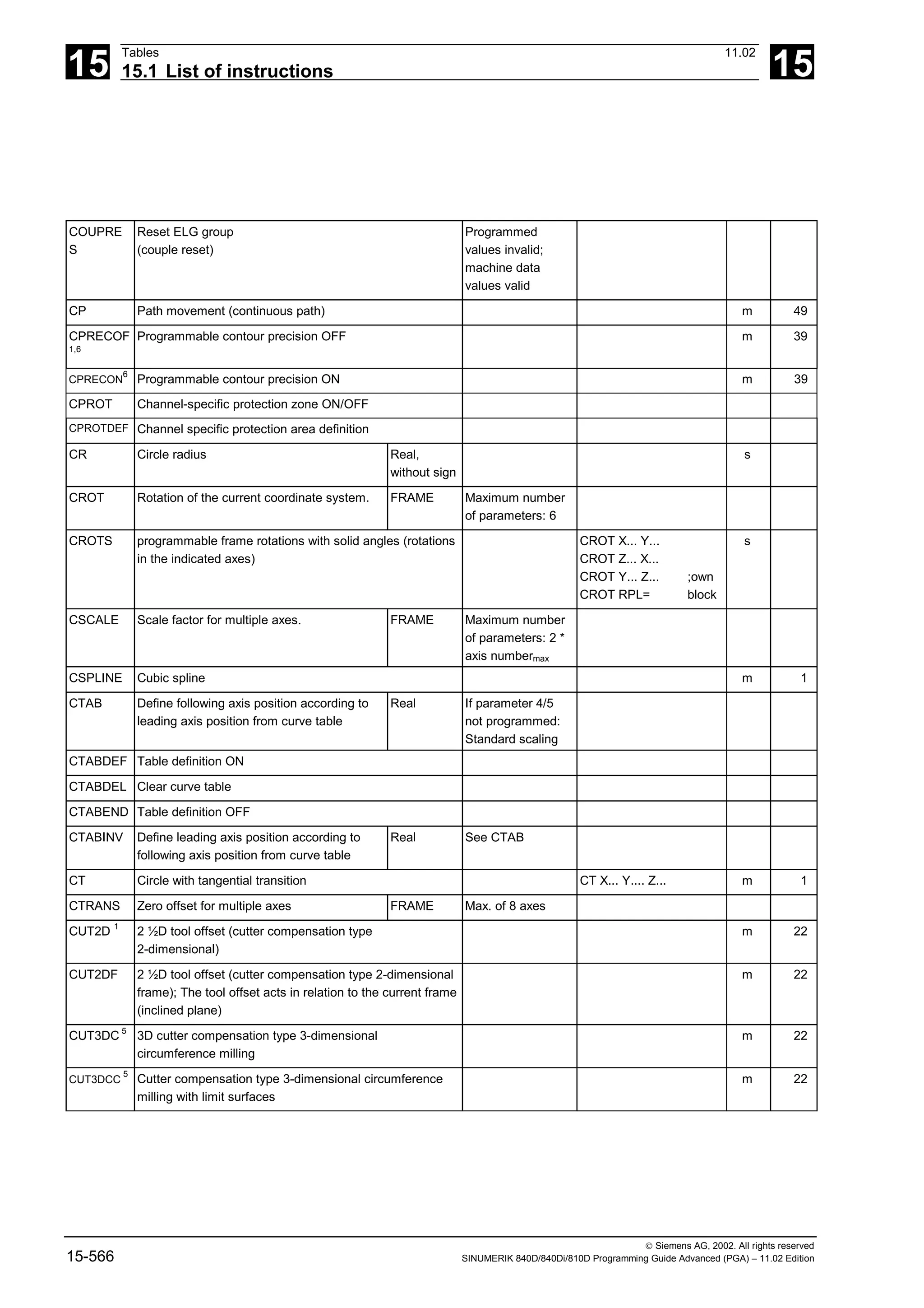
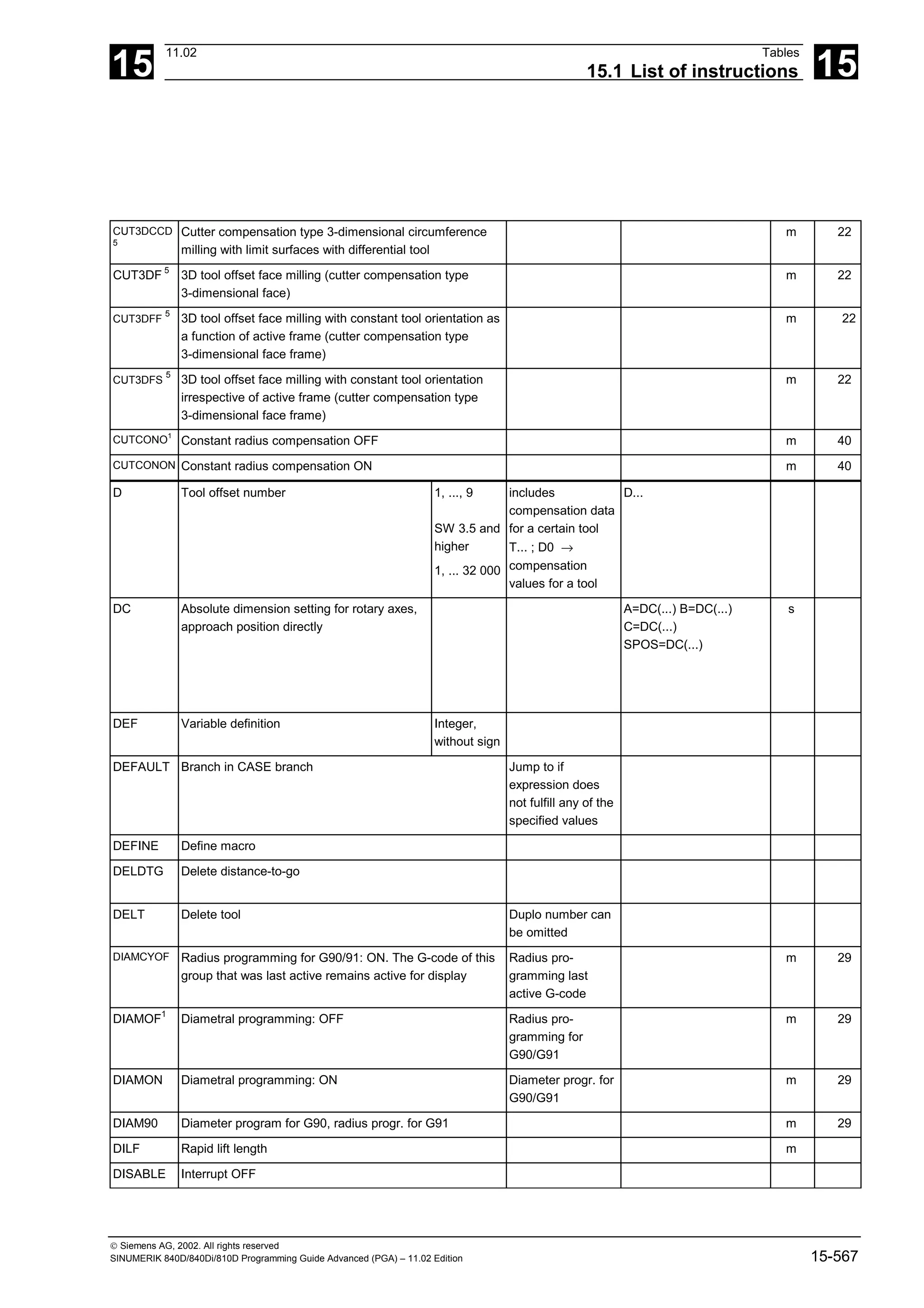
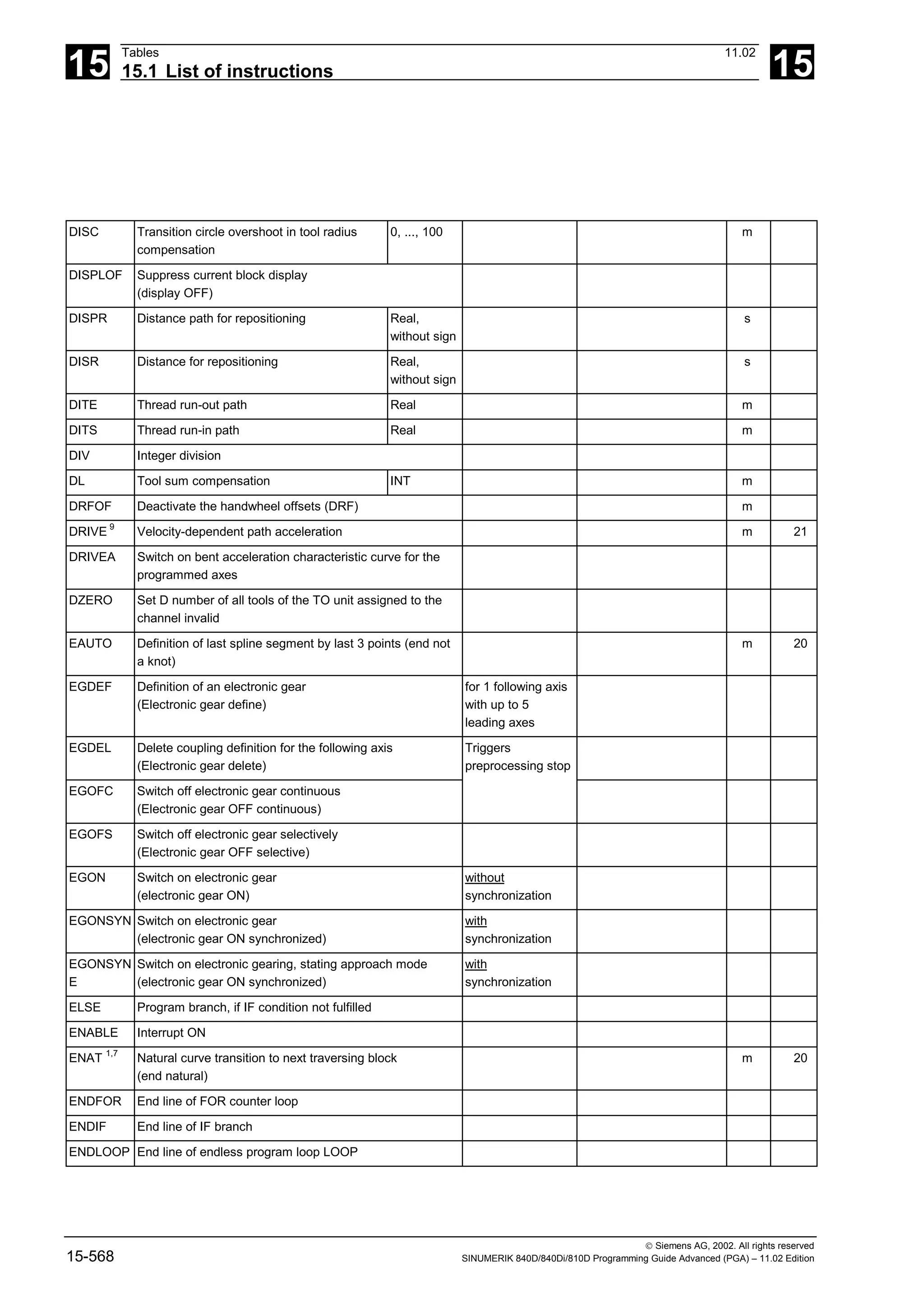
![15
11.02 Tables
15.1 List of instructions 15
Siemens AG, 2002. All rights reserved
SINUMERIK 840D/840Di/810D Programming Guide Advanced (PGA) – 11.02 Edition 15-569
ENDPROC End line of program with start line PROC
ENDWHILE End line of WHILE loop
ETAN Tangential curve transition to next traversing block at
beginning of spline (end tangential)
m 20
EVERY Execute synchronized action if condition changes from
FALSE to TRUE
EXECSTR
ING
Transfer of a string variable with the parts program line to
run
Indirect parts
program line
EXECSTRING(MFCT1
<< M4711)
EXECTAB Execute an element from a motion table
(execute table)
EXECUTE Program execution ON Switch back to
normal program
execution from
reference point edit
mode or after
creating a
protection zone
EXP Exponent function ex
Real
EXTCALL Run external subprogram Reload program
from HMI in
"Processing from
external source"
mode
EXTERN Broadcast a subroutine with parameter passing
F Feed value
(dwell time is also programmed under F in
conjunction with G4)
0.001, ...,
99 999.999
Tool/workpiece
path velocity;
Dimension in
mm/min or
mm/revolution as a
function of G94 or
G95
F=100 G1 ...
FA Axial feed (feed axial) 0.001, ...,
999999.999
mm/min,
degree/min;
0.001, ...,
39999.9999
inch/min
FA[X]=100 m
FAD Infeed feedrate for smooth approach and
retraction
(Feed approach / depart)
Real,
without sign
FALSE Logical constant: False BOOL Can be replaced
with integer
constant 0](https://image.slidesharecdn.com/fadaladvancedprogrammingmanual-220505063253/75/Fadal-Advanced-Programming-Manual-pdf-569-2048.jpg)
![15
Tables 11.02
15.1 List of instructions 15
Siemens AG, 2002. All rights reserved
15-570 SINUMERIK 840D/840Di/810D Programming Guide Advanced (PGA) – 11.02 Edition
FCTDEF Define polynomial function Is evaluated in
SYFCT or
PUTFTOCF.
FCUB
6
Feed variable according to cubic spline
(feed cubic)
m 37
FD Path feed for handwheel override
(feed DRF)
Real,
without sign
s
FDA Axial feed for handwheel override
(feed DRF axial)
Real,
without sign
s
FENDNORM Corner deceleration OFF m 57
FFWOF 1
Feedforward control OFF (feed forward OFF) m 24
FFWON Feedforward control ON (feed forward ON) m 24
FGREF Reference radius m
FGROUP Define axis(axes) with path feed F applies to all
axes programmed
under FGROUP
FGROUP (Axis1, [Axis2],
...)
FIFOCTRL Control of the preprocessing memory m 4
FIFOLEN Programmable preprocessing depth
FINEA Motion end when "Exact stop fine" reached FINEA=... or FINEA[n]=.. m
FL Limit velocity for synchronous axes
(feed limit)
Real,
without sign
The unit set with
G93, G94, G95
applies (max. rapid
traverse)
FL [Axis] =... m
FLIN
6
Linearly variable feed (feed linear) m 37
FMA Feed multiple axial Real,
without sign
m
FNORM
1,6
Normal feed acc. to DIN66025 (feed normal) m 37
FOR Counter loop with fixed number of passes
FORI1 Feed for swiveling the orientation vector on the large
circle
m
FORI2 Feed for the overlaid rotation around the swiveled
orientation vector
m
FP Fixed point: numb. of fixed points to be
approached
Integer,
without sign
G75 FP=1 s
FPO Feed characteristic programmed via a
polynomial
(feed polynomial)
Real Quadratic, cubic
polynomial
coefficient
FPR Rotary axis identification 0.001 ...
999999.999
FPR (rotary axis)
FPRAOF Deactivate revolutional feedrate
FPRAON Activate revolutional feedrate](https://image.slidesharecdn.com/fadaladvancedprogrammingmanual-220505063253/75/Fadal-Advanced-Programming-Manual-pdf-570-2048.jpg)
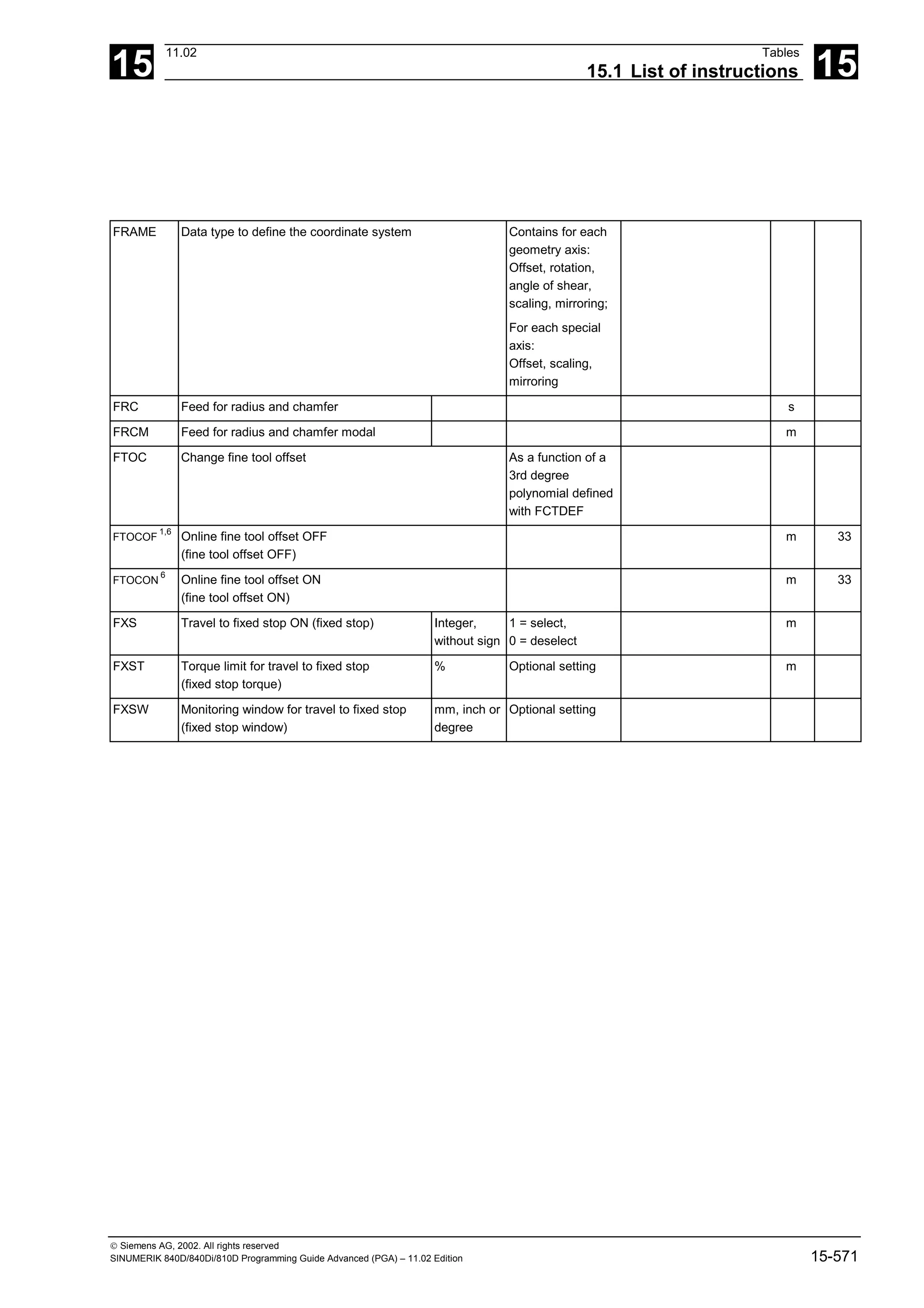
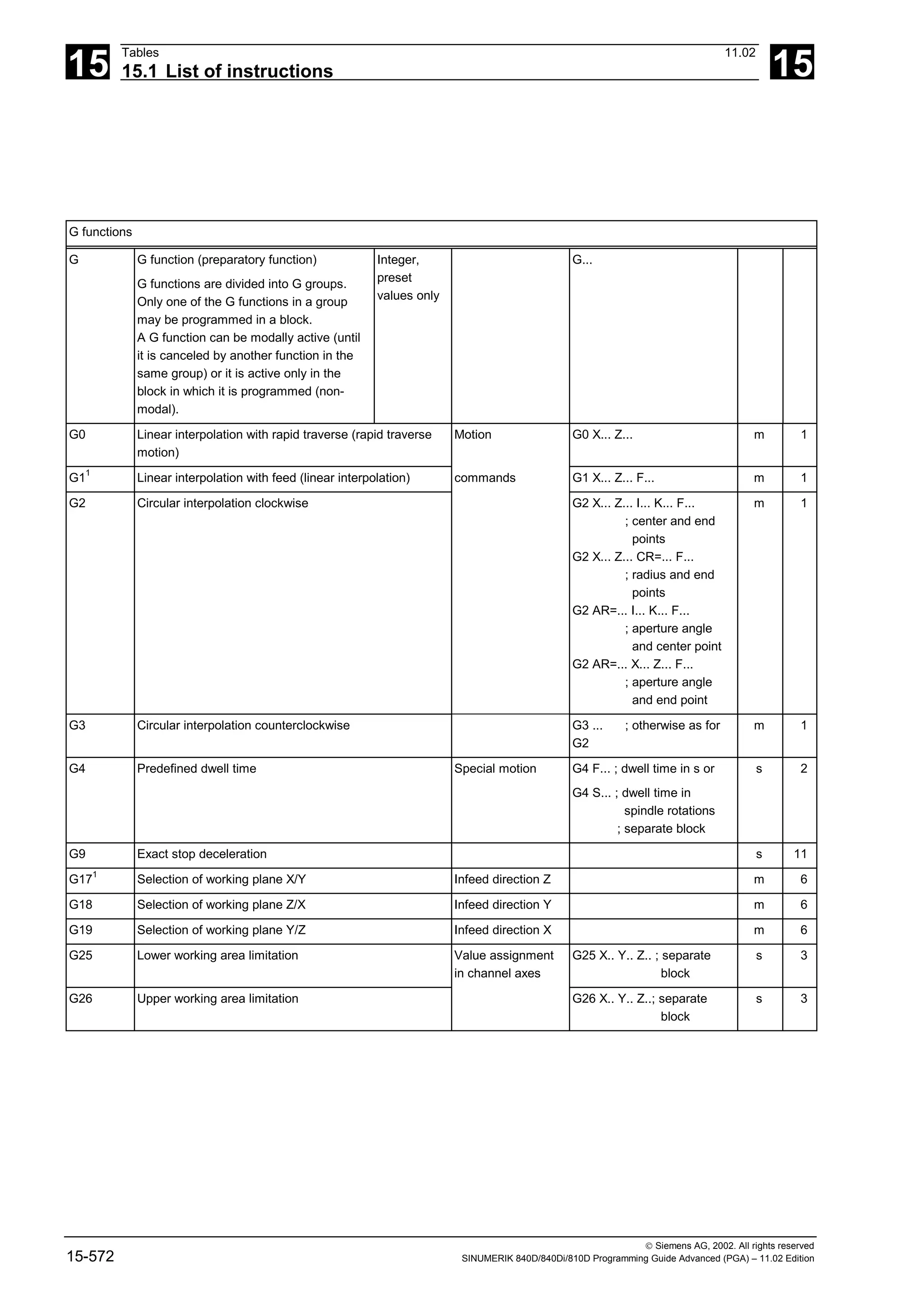
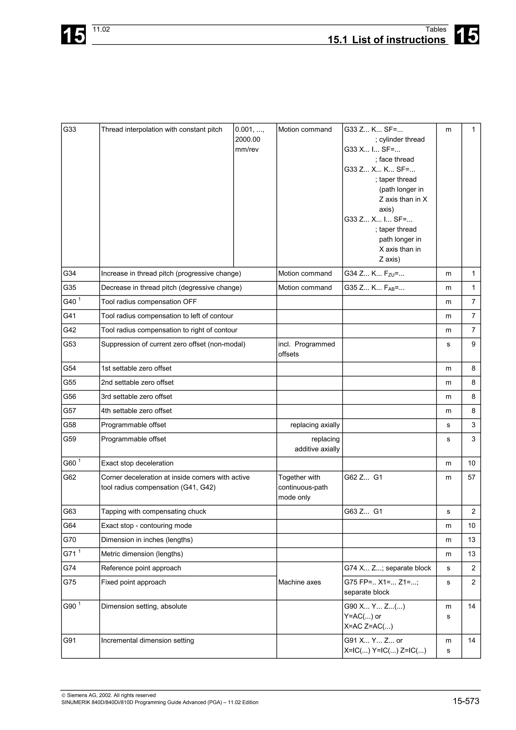
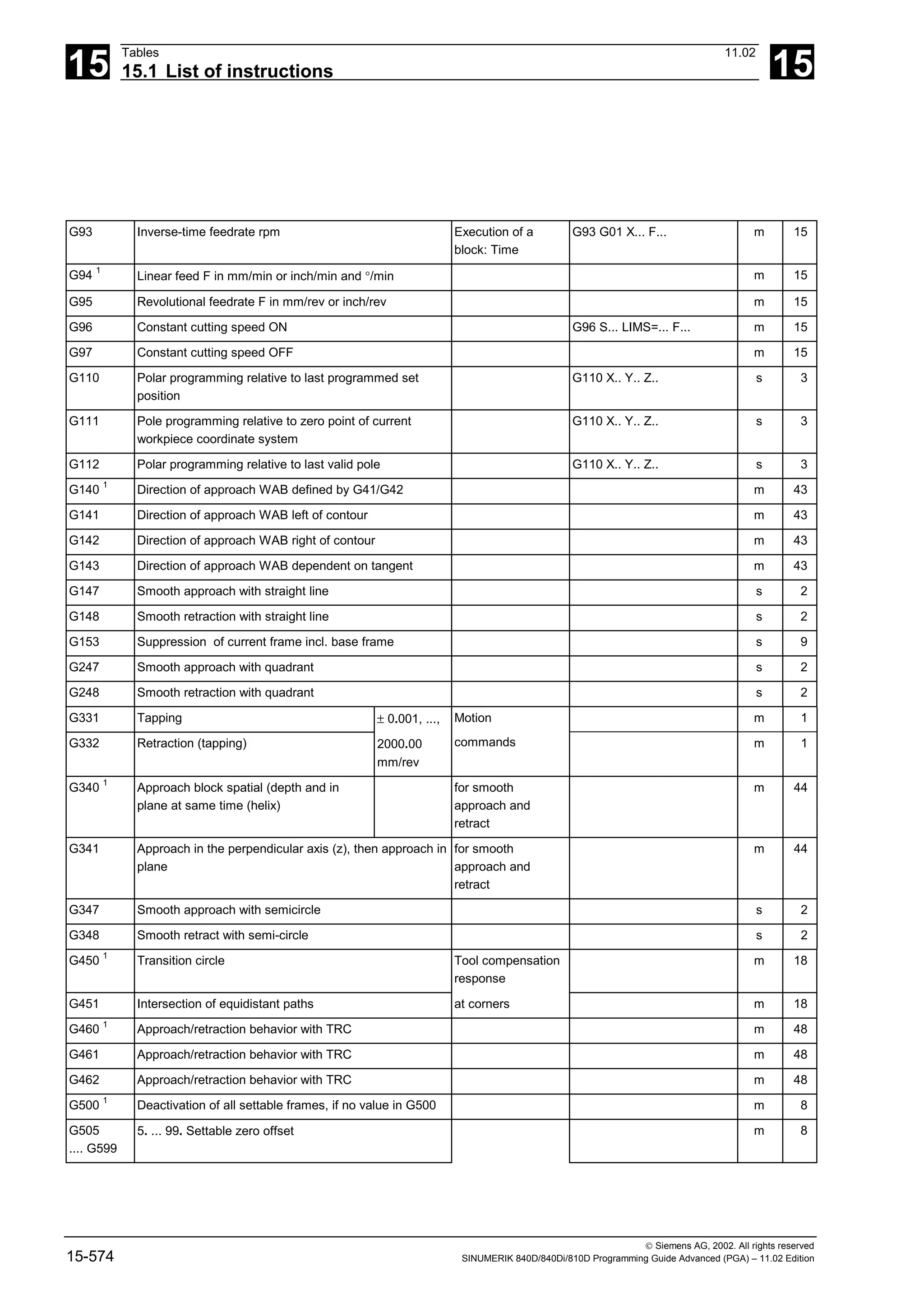
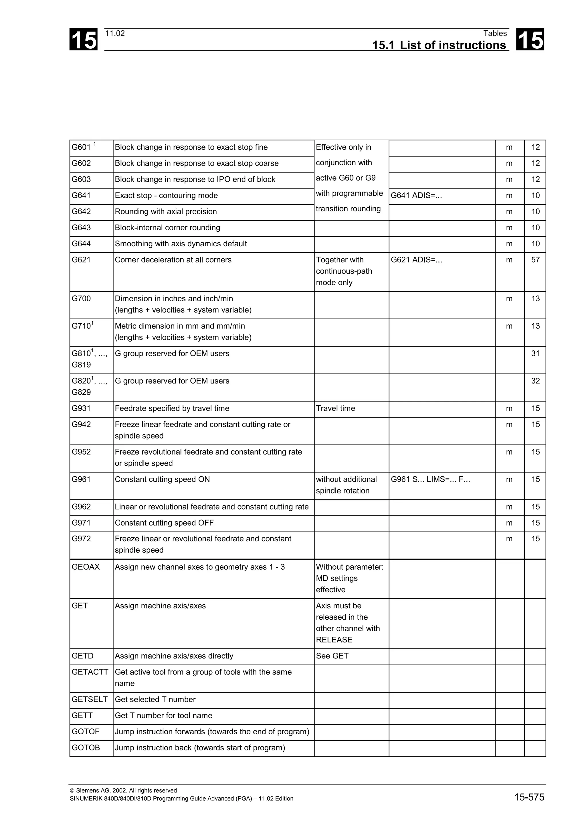
![15
Tables 11.02
15.1 List of instructions 15
Siemens AG, 2002. All rights reserved
15-576 SINUMERIK 840D/840Di/810D Programming Guide Advanced (PGA) – 11.02 Edition
GOTO Jump instruction first forward then backward (direction
initially to end of program and then to start of program
GOTOC Alarm 14080 Suppress jump destination not found. see GOTO
GWPSOF Deselect constant grinding wheel peripheral speed
(GWPS)
GWPSOF (T No.) s
GWPSON Select constant grinding wheel peripheral speed
(GWPS)
GWPSON (T No.) s
H... Auxiliary function output to PLC Real/INT Settable via MD
(machine
manufacturer)
H100 or H2=100
I 4
Interpolation parameter Real s
I1 Intermediate point coordinate Real s
IC Incremental dimension setting 0, ...,
±99999.999°
X=IC(10) s
IDS Identification of static synchronized actions
IF Introduce conditional jump Structure: IF - ELSE
- ENDIF
INDEX Define index of character in input string 0, ...,
INT
String: Param. 1,
character: Param. 2
INIT Select module for execution in a channel
INT Data type: Integer with leading sign - (231
-1), ...,
231
-1
INTERSEC Calculate intersection between two
contour elements
VAR REAL
[2]
Error status BOOL
IP Variable interpolation parameter Real
IPOBRKA Motion criterion from braking ramp activation Braking ramp with
100% to 0%
IPOBRKA=.. or
IPOBRKA(<axis>[,REAL])
m
IPOENDA Motion end when "IPO stop" reached IPOENDA=.. or
IPOENDA[n]..
m
ISAXIS Check if geometry axis 1 – 3 specified as
parameter exist
BOOL
ISD Insertion depth Real m
ISNUMBER Check whether the input string can be
converted to a number
BOOL Convert input string
to number
ISVAR Check whether the transfer parameter
contains a variable known in the NC
BOOL Machine data,
setting data and
variables as GUDs
J 4
Interpolation parameter Real s
J1 Intermediate point coordinate Real s
JERKA Activate acceleration response set via machine data for
programmed axes
K 4
Interpolation parameter Real s
K1 Intermediate point coordinate Real s](https://image.slidesharecdn.com/fadaladvancedprogrammingmanual-220505063253/75/Fadal-Advanced-Programming-Manual-pdf-576-2048.jpg)
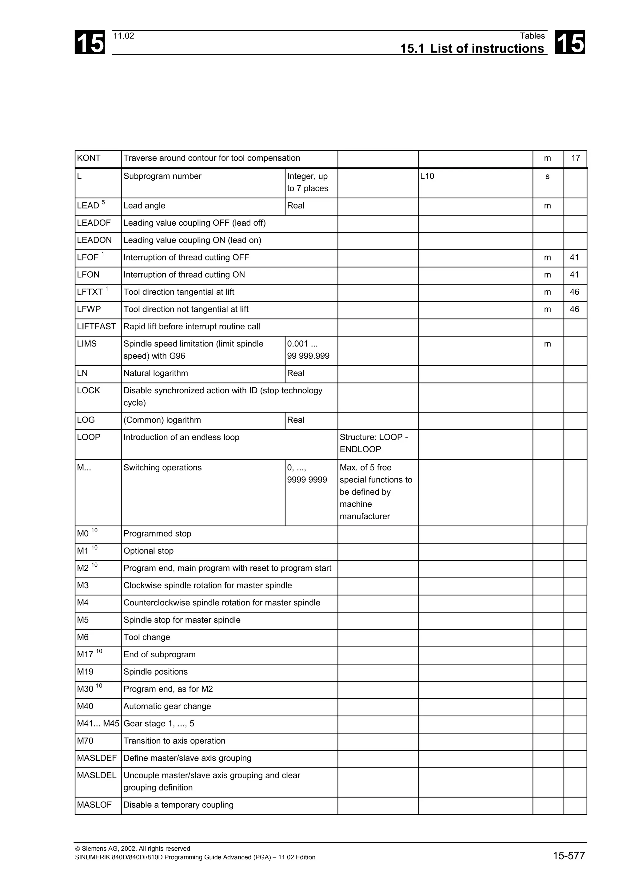
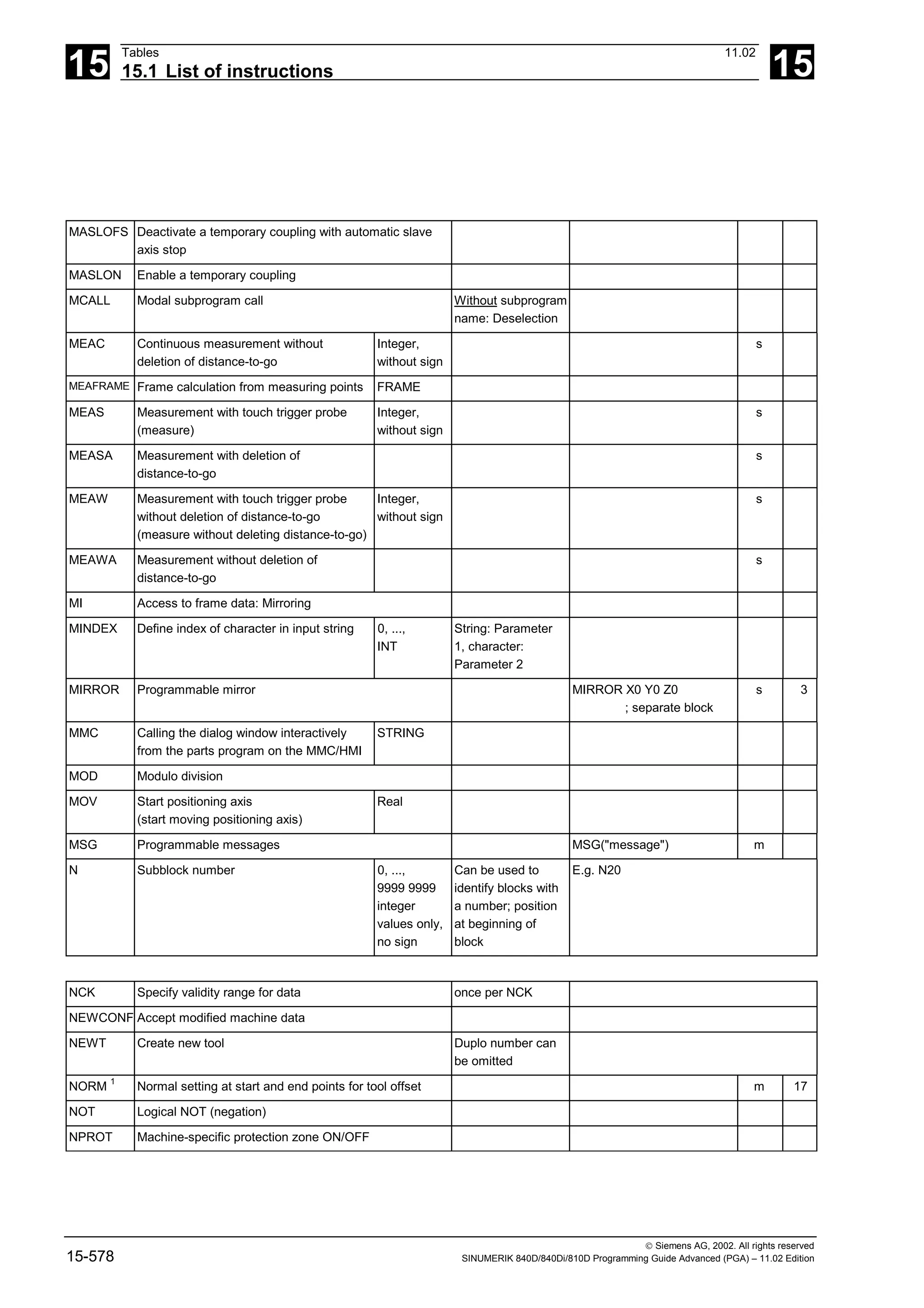
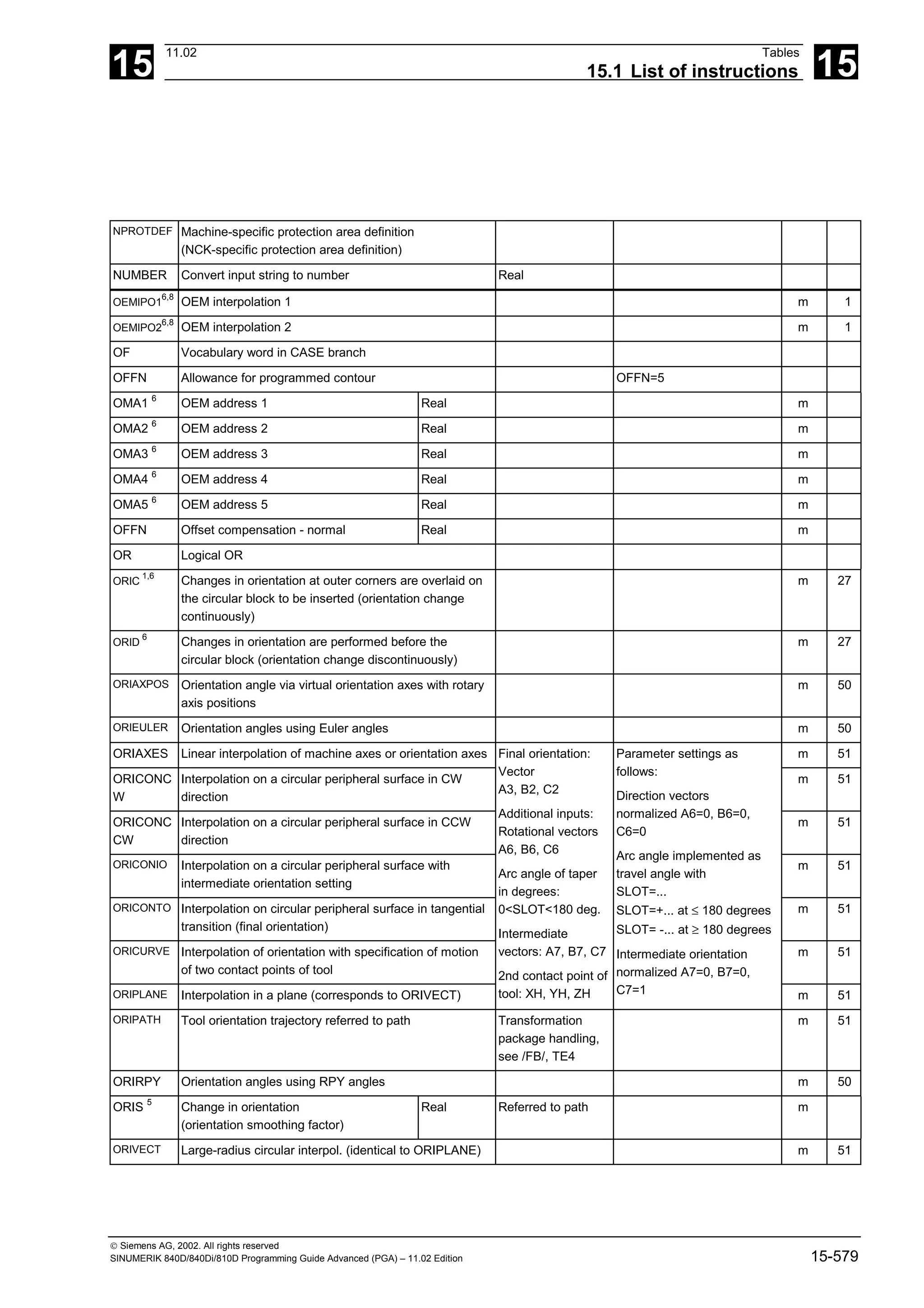
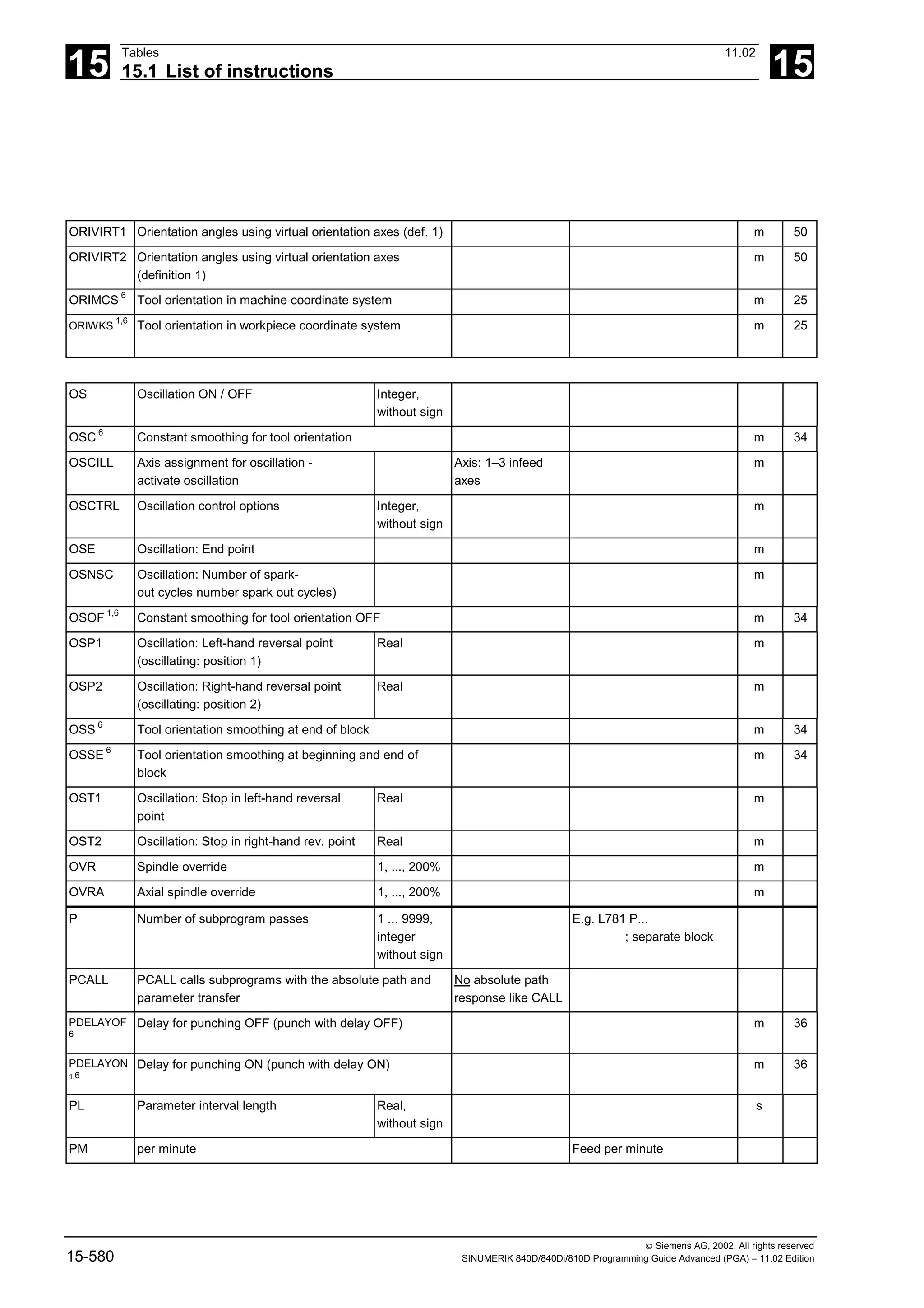
![15
11.02 Tables
15.1 List of instructions 15
Siemens AG, 2002. All rights reserved
SINUMERIK 840D/840Di/810D Programming Guide Advanced (PGA) – 11.02 Edition 15-581
PO Polynomial Real,
without sign
s
POLF Position LIFTFAST Real,
without sign
POLF[Y]=10 m
POLY 5
Polynomial interpolation m 1
POLYPATH
5
Polynomial interpolation can be selected for the AXIS or
VECT axis groups
POLYPATH ("AXES")
POLYPATH ("VECT")
m 1
PON 6
Punching ON (punch ON) m 35
PONS 6
Punching ON in IPO cycle (punch ON slow) m 35
POS Position axis POS[X]=20
POSA Position axis across block boundaries POSA[Y]=20
POSP Positioning in part sections (oscillation)
(Position axis in parts)
Real: End
position,
part length;
Integer:
option
POT Square (arithmetic function) Real
PR Per revolution Revolutional feedrate
PRESETON Set actual value for programmed axes An axis name is
programmed with
the corresponding
value in the next
parameter.
Up to 8 axes
possible
PRESETON(X,10,Y,4.5)
PRIO Vocabulary word for setting the priority for interrupt
processing
PROC First instruction in a program Block number - PROC -
identifier
PTP Point to point movement m 49
PUTFTOC Tool offset fine for parallel dressing (continuous
dressing)
PUTFTOCF Put fine tool correction function dependent:
Fine tool offset dependent on a function for continuous
dressing defined with FCtDEF
PW Point weight Real,
without sign
s
QECLRNOF Quadrant error compensation learning OFF
QECLRNON Quadrant error compensation learning ON
QU Fast additional (auxiliary) function output](https://image.slidesharecdn.com/fadaladvancedprogrammingmanual-220505063253/75/Fadal-Advanced-Programming-Manual-pdf-581-2048.jpg)
![15
Tables 11.02
15.1 List of instructions 15
Siemens AG, 2002. All rights reserved
15-582 SINUMERIK 840D/840Di/810D Programming Guide Advanced (PGA) – 11.02 Edition
R... Arithmetic parameters
SW 5 and higher:
also as settable address identifier and
with numerical extension
±0.0000001,
...,
9999 9999
R parameter
number can be set
via MD
R10=3 ;R parameter
assignment
X=R10 ;Axis value
R[R10]=6 ;indirect
programming
RDISABLE Read-in disable
READAL Read alarm Alarms are
searched according
to ascending
numbers
REAL Data type: floating point variable with
leading sign (real numbers)
Correspond
s to the 64-
bit floating
point format
of the
processor
REDEF Setting for machine data, which user groups they are
displayed for
RELEASE Release machine axes Multiple axes can
be programmed
REP Vocabulary word for initialization of all elements of an
array with the same value
REPEAT Repeat a program loop until (UNTIL) a
condition is fulfilled
REPEATB Repeat a program line nnn times
REPOSA Reposition all axes linearly s 2
REPOSH Reposition along semi-circle s 2
REPOSHA Reposition all axes along semi-circle: Reposition all
axes, geometry axes along quadrant
s 2
REPOSL Reposition linearly s 2
REPOSQ Reposition along quadrant s 2
REPOSQA Reposition all axes along quadrant
Reposition all axes linearly, geometry axes along
quadrant
s 2
RESET Reset technology cycle One or several IDs
can be programmed
RET End of subprogram Use in place of M17
– without function
output to PLC
RET](https://image.slidesharecdn.com/fadaladvancedprogrammingmanual-220505063253/75/Fadal-Advanced-Programming-Manual-pdf-582-2048.jpg)
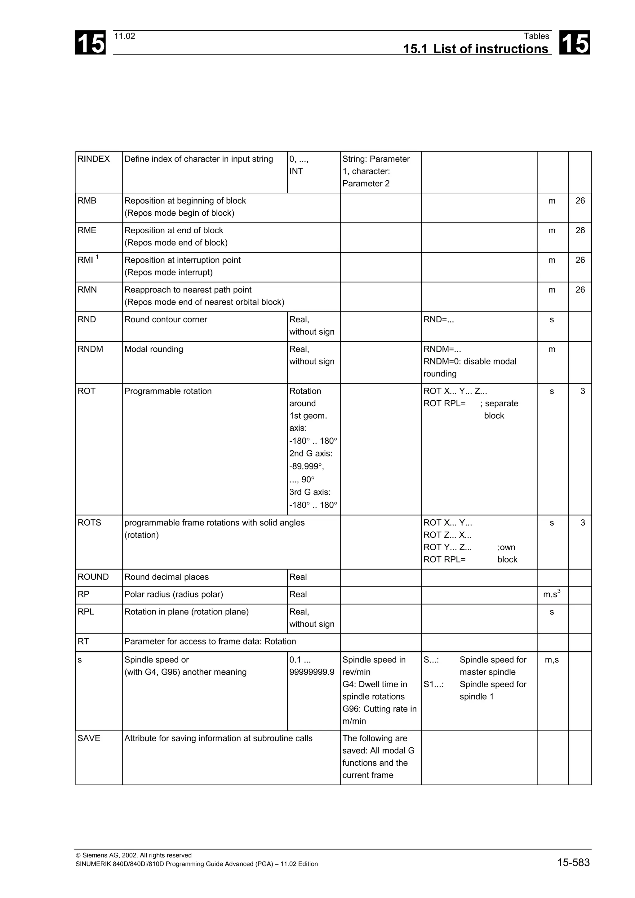
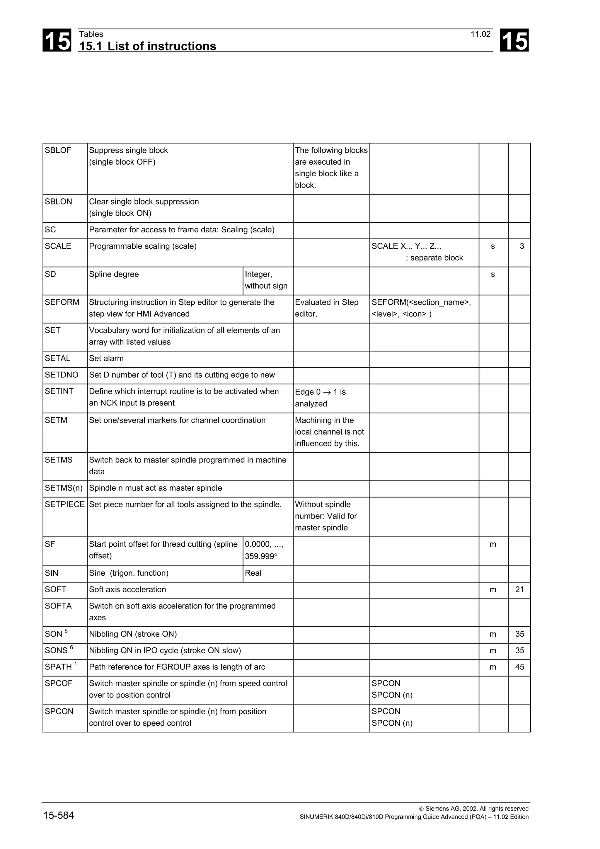
![15
11.02 Tables
15.1 List of instructions 15
Siemens AG, 2002. All rights reserved
SINUMERIK 840D/840Di/810D Programming Guide Advanced (PGA) – 11.02 Edition 15-585
SPIF1 1,6
High-speed NCK inputs/outputs for punching/nibbling
byte 1 (stroke/punch interface 1)
see /FB/, N4:
Punching and
Nibbling
m 38
SPIF2 6
High-speed NCK inputs/outputs for punching/nibbling
byte 2 (stroke/punch interface 2)
see /FB/, N4:
Punching and
Nibbling
m 38
SPLINE-
PATH
Define spline grouping Max. of 8 axes
SPOF 1,6
Stroke OFF, punching, nibbling OFF (stroke/punch
OFF)
m 35
SPN 6
Number of path sections per block
(stroke/punch number)
Integer s
SPP 6
Length of a path section
(stroke/punch path)
Integer m
SPOS Spindle position SPOS=10 or SPOS[n]=10 m
SPOSA Spindle position across block boundaries SPOSA=5 or SPOSA[n]=5 m
SQRT Square root; arithmetic function Real
SR Sparking-out retraction path for
synchronized action
Real,
without sign
s
SRA Sparking-out retraction path with input
axial for synchronized action
SRA[Y]=0.2 m
ST Sparking-out time for synchronized action Real,
without sign
s
STA Sparking out time axial for synchronized
action
m
START Start selected programs simultaneously in several
channels from current program
ineffective for the
local channel
STAT Position of articulated joints Integer s
STARTFIFO1
Execute; fill preprocessing buffer in parallel m 4
STOPFIFO Stop processing; fill preprocessing buffer until
STARTFIFO, preprocessing buffer "full" or end of
program is detected
m 4
STOPRE Stop preprocessing until all prepared blocks are
executed in main run.
STOPREOF Stop preprocessing OFF
STRING Data type: String Max. 200
characters
STRLEN Define string length INT
SUBSTR Define index of character in input string Real String: Parameter
1, character:
Parameter 2](https://image.slidesharecdn.com/fadaladvancedprogrammingmanual-220505063253/75/Fadal-Advanced-Programming-Manual-pdf-585-2048.jpg)
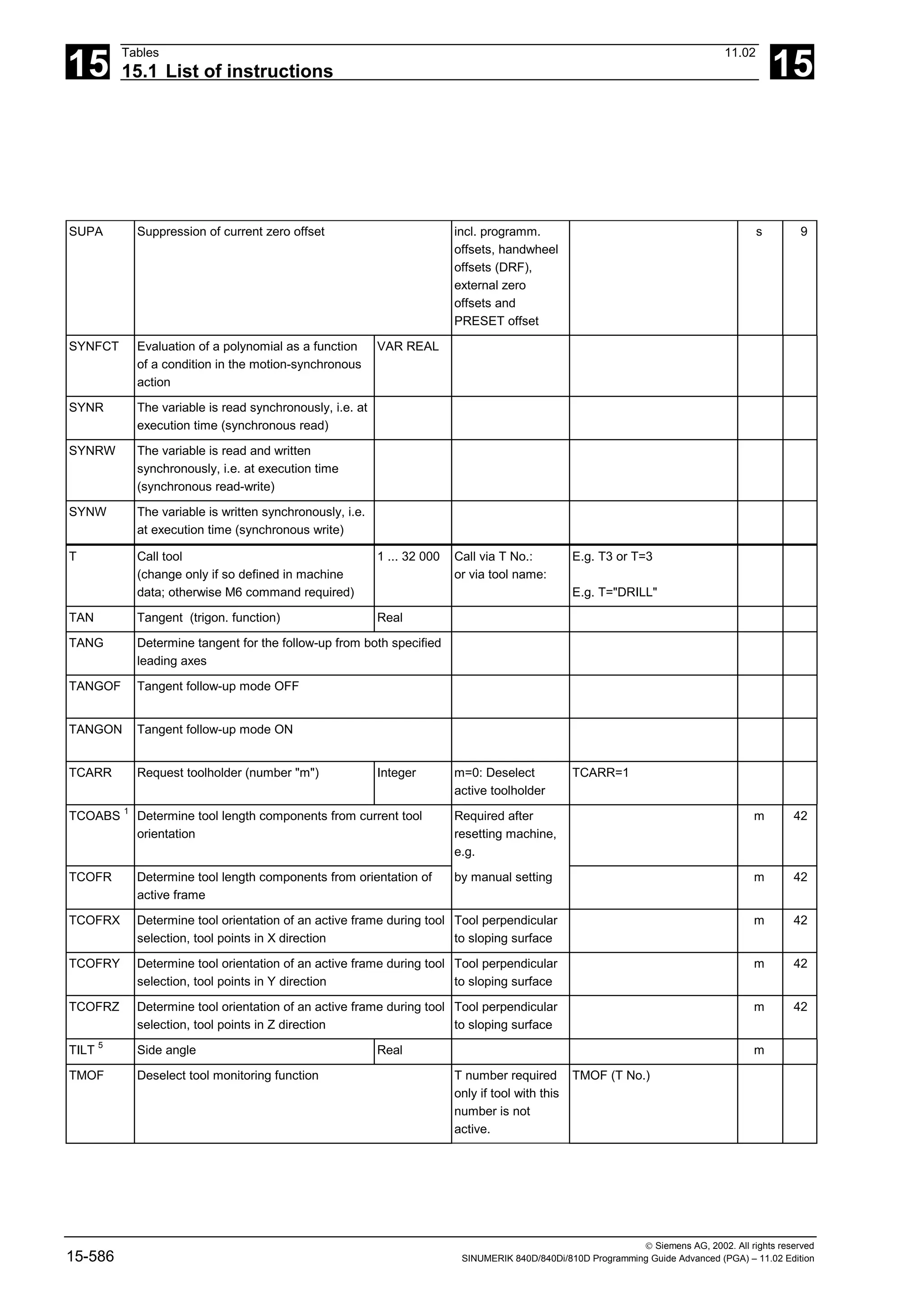
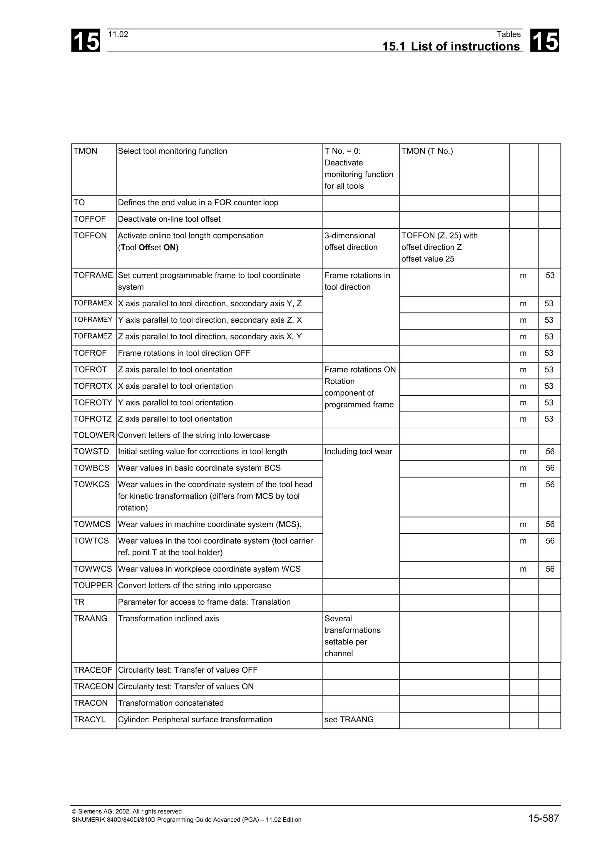
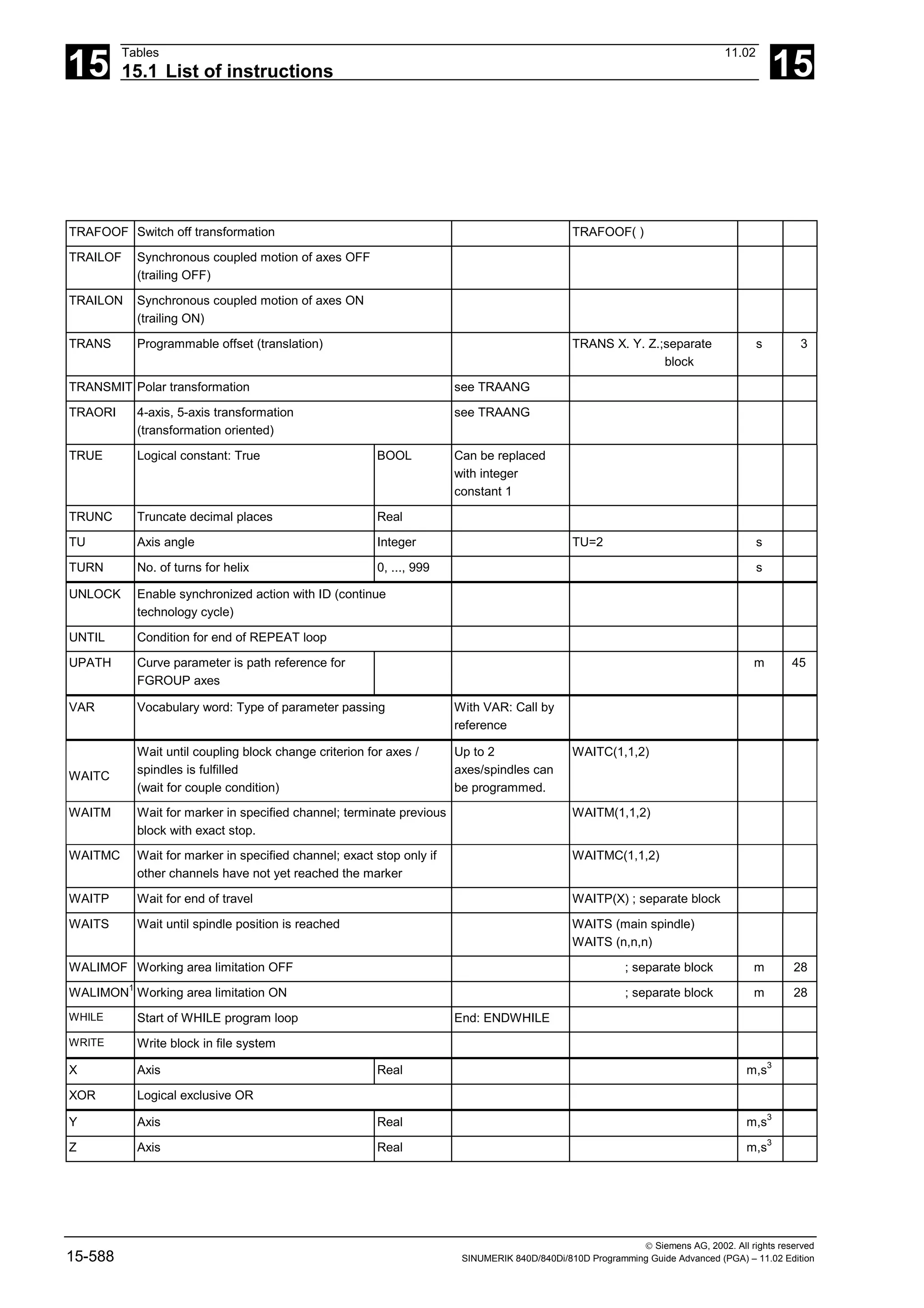
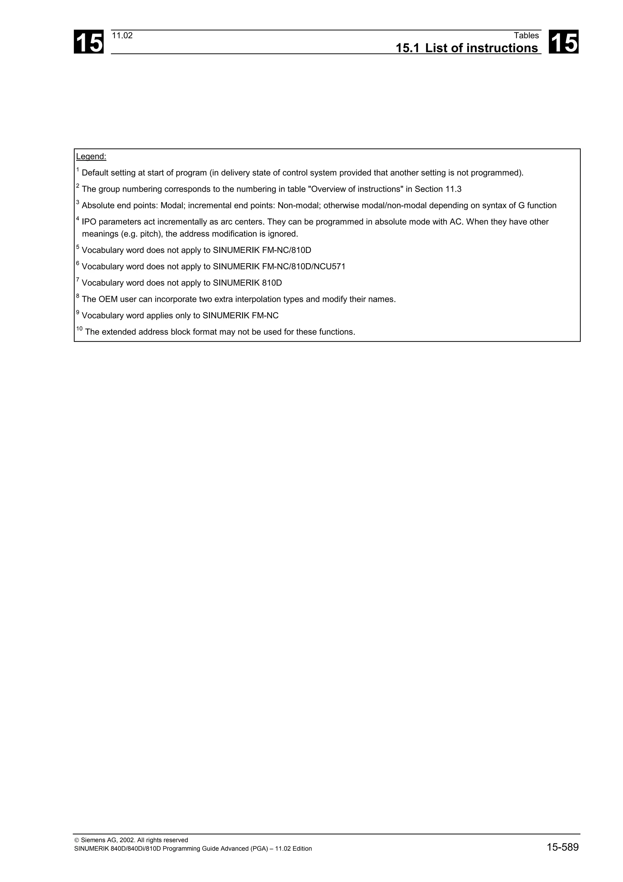

![15
11.02 Tables
15.2 List of system variables 15
Siemens AG, 2002. All rights reserved
SINUMERIK 840D/840Di/810D Programming Guide Advanced (PGA) – 11.02 Edition 15-591
15.2 List of system variables
Legend:
Parts pr. Parts program
Syn Synchronized action
O The index can be calculated online in
synchronized actions. (+)
S Software version
R Read access possible
W Write access possible
RS A preprocessor stop takes
place implicitly on read access
WS A preprocessor stop takes place
implicitly on write access
+ In column O: The index can be
calculated online in synchronized
actions.
15.2.1 R parameters
Identifier Type Description: System variable/value range/index Parts pr. Syn O S
R
$R
REAL Rn or R[n]
The max. number of R parameters is defined in machine data
R W
R W
1
4
15.2.2 Channel-specific synchronized action variables
$AC_PARAM REAL $AC_PARAM[n]
Arithmetic variable for motion-synchronized actions
The dimension is fixed by the machine data
$MC_MM_NUM_AC_PARAM.
R
S
W
S
R W + 3
$AC_SYSTEM_
PARAM
REAL $AC_SYSTEM_PARAM[n]
Arithmetic variable for motion-synchronized actions
Reserved for SIEMENS applications
The dimension is fixed by the machine data
$MC_MM_NUM_AC_SYSTEM_PARAM.
R
S
W
S
R W + 6
.
3
$AC_MARKER INT $AC_MARKER[n]
Marker variable for motion-synchronized actions
The dimension is fixed by the machine data
$MC_MM_NUM_AC_MARKER.
R
S
W
S
R W + 2](https://image.slidesharecdn.com/fadaladvancedprogrammingmanual-220505063253/75/Fadal-Advanced-Programming-Manual-pdf-591-2048.jpg)
![15
Tables 11.02
15.2 List of system variables 15
Siemens AG, 2002. All rights reserved
15-592 SINUMERIK 840D/840Di/810D Programming Guide Advanced (PGA) – 11.02 Edition
Identifier Type Description: System variable/value range/index Parts pr. Syn O S
$AC_SYSTEM_
MARKER
INT $AC_SYSTEM_MARKER[n]
Marker variable for motion-synchronized actions
Reserved for SIEMENS applications
The dimension is fixed by the machine data
$MC_MM_NUM_AC_SYSTEM_MARKER.
R
S
W
S
R W + 6
.
3
15.2.3 Frames 1
$P_UIFR FRAME $P_UIFR[n]
Settable frames, can be activated via G500, G54 .. G599.
5 to 100 settable frames with MD
$MC_MM_NUM_USER_FRAMES
R W 2
$P_CHBFR FRAME $P_CHBFR[n]
Channel base frames, can be activated via G500, G54 .. G599.
0 to 8 channel base frames via MD
$MC_MM_NUM_BASE_FRAMES.
R W 5
$P_SETFR FRAME $P_SETFR
Axes: (geometry axis, channel axis, machine axis)
R W 6
.
1
$P_EXTFR FRAME $P_EXTFR
Axes: (geometry axis, channel axis, machine axis)
R W 6
.
1
$P_PARTFR FRAME $P_PARTFR
Axes: (geometry axis, channel axis, machine axis)
R W 6
.
1
$P_TOOLFR FRAME $P_TOOLFR
Axes: (geometry axis, channel axis, machine axis)
R W 6
.
1
$P_WPFR FRAME $P_WPFR
Axes: (geometry axis, channel axis, machine axis)
R W 6
.
3
$P_CYCFR FRAME $P_CYCFR
Axes: (geometry axis, channel axis, machine axis)
R W 6
.
3](https://image.slidesharecdn.com/fadaladvancedprogrammingmanual-220505063253/75/Fadal-Advanced-Programming-Manual-pdf-592-2048.jpg)
![15
11.02 Tables
15.2 List of system variables 15
Siemens AG, 2002. All rights reserved
SINUMERIK 840D/840Di/810D Programming Guide Advanced (PGA) – 11.02 Edition 15-593
Identifier Type Description: System variable/value range/index Parts pr. Syn O S
$P_TRAFR FRAME $P_TRAFR
Axes: (geometry axis, channel axis, machine axis)
R W 6
.
4
$P_NCBFR FRAME $P_NCBFR[n]
NCU base frames, can be activated via G500, G54 .. G599.
0 to 8 NCU base frames via MD
$MN_MM_NUM_GLOBAL_BASE_FRAMES.
R W 5
15.2.4 Toolholder data
Identifier Type Description: System variable/value range/index Parts pr. Syn O S
$TC_CARR1 REAL $TC_CARR1[n]
x component of offset vector l1
Notice! All system parameters with the '$TC_' prefix are
contained in the TOA area.
The special property of this area is that it is possible,
conditional on machine data 28085 = MM_LINK_TOA_UNIT,
for various NCK channels to access these parameters.
If an NCK parameterization of this type has been selected, then
it must be clearly understood that when this data is changed,
the changes can may also have an adverse effect on another
channel; or there must be evidence that the change only has a
local effect on the channel that is changed.
The max. number of toolholders can be set via machine data.
Default setting is = 0; i.e. NCK has no such data.
R W 4
$TC_CARR2 REAL $TC_CARR2[n]
y component of offset vector l1
The max. number of toolholders can be set via machine data.
Default setting is = 0; i.e. NCK has no such data.
R W 4](https://image.slidesharecdn.com/fadaladvancedprogrammingmanual-220505063253/75/Fadal-Advanced-Programming-Manual-pdf-593-2048.jpg)
![15
Tables 11.02
15.2 List of system variables 15
Siemens AG, 2002. All rights reserved
15-594 SINUMERIK 840D/840Di/810D Programming Guide Advanced (PGA) – 11.02 Edition
Identifier Type Description: System variable/value range/index Parts pr. Syn O S
$TC_CARR3 REAL $TC_CARR3[n]
z component of offset vector l1
The max. number of toolholders can be set via machine data.
Default setting is = 0; i.e. NCK has no such data.
R W 4
$TC_CARR4 REAL $TC_CARR4[n]
x component of offset vector l2
The max. number of toolholders can be set via machine data.
Default setting is = 0; i.e. NCK has no such data.
R W 4
$TC_CARR5 REAL $TC_CARR5[n]
y component of offset vector l2
The max. number of toolholders can be set via machine data.
Default setting is = 0; i.e. NCK has no such data.
R W 4
$TC_CARR6 REAL $TC_CARR6[n]
z component of offset vector l2
The max. number of toolholders can be set via machine data.
Default setting is = 0; i.e. NCK has no such data.
R W 4
$TC_CARR7 REAL $TC_CARR7[n]
x component of axis of rotation v1
The max. number of toolholders can be set via machine data.
Default setting is = 0; i.e. NCK has no such data.
R W 4
$TC_CARR8 REAL $TC_CARR8[n]
y component of axis of rotation v1
The max. number of toolholders can be set via machine data.
Default setting is = 0; i.e. NCK has no such data.
R W 4
$TC_CARR9 REAL $TC_CARR9[n]
z component of axis of rotation v1
The max. number of toolholders can be set via machine data.
Default setting is = 0; i.e. NCK has no such data.
R W 4
$TC_CARR10 REAL $TC_CARR10[n]
x component of axis of rotation v2
The max. number of toolholders can be set via machine data.
Default setting is = 0; i.e. NCK has no such data.
R W 4
$TC_CARR11 REAL $TC_CARR11[n]
y component of axis of rotation v2
The maximum number of toolholders can be set via
machine data.
Default setting is = 0; i.e. NCK has no such data.
R W 4](https://image.slidesharecdn.com/fadaladvancedprogrammingmanual-220505063253/75/Fadal-Advanced-Programming-Manual-pdf-594-2048.jpg)
![15
11.02 Tables
15.2 List of system variables 15
Siemens AG, 2002. All rights reserved
SINUMERIK 840D/840Di/810D Programming Guide Advanced (PGA) – 11.02 Edition 15-595
Identifier Type Description: System variable/value range/index Parts pr. Syn O S
$TC_CARR12 REAL $TC_CARR12[n]
z component of axis of rotation v2
The max. number of toolholders can be set via machine data.
Default setting is = 0; i.e. NCK has no such data.
R W 4
$TC_CARR13 REAL $TC_CARR13[n]
Angle of rotation alpha1 (in degrees)
The max. number of toolholders can be set via machine data.
Default setting is = 0; i.e. NCK has no such data.
R W 4
$TC_CARR14 REAL $TC_CARR14[n]
Angle of rotation alpha2 (in degrees)
The max. number of toolholders can be set via machine data.
Default setting is = 0; i.e. NCK has no such data.
R W 4
$TC_CARR15 REAL $TC_CARR15[n]
x component of offset vector l3
The max. number of toolholders can be set via machine data.
Default setting is = 0; i.e. NCK has no such data.
R W 5
$TC_CARR16 REAL $TC_CARR16[n]
y component of offset vector l3
The max. number of toolholders can be set via machine data.
Default setting is = 0; i.e. NCK has no such data.
R W 5
$TC_CARR17 REAL $TC_CARR17[n]
z component of offset vector l3
The max. number of toolholders can be set via machine data.
Default setting is = 0; i.e. NCK has no such data.
R W 5
$TC_CARR18 REAL $TC_CARR18[n]
x component of offset vector l4
The max. number of toolholders can be set via machine data.
Default setting is = 0; i.e. NCK has no such data.
R W 6
.
1
$TC_CARR19 REAL $TC_CARR19[n]
y component of offset vector l4
The max. number of toolholders can be set via machine data.
Default setting is = 0; i.e. NCK has no such data.
R W 6
.
1
$TC_CARR20 REAL $TC_CARR20[n]
z component of offset vector l4
The max. number of toolholders can be set via machine data.
Default setting is = 0; i.e. NCK has no such data.
R W 6
.
1](https://image.slidesharecdn.com/fadaladvancedprogrammingmanual-220505063253/75/Fadal-Advanced-Programming-Manual-pdf-595-2048.jpg)
![15
Tables 11.02
15.2 List of system variables 15
Siemens AG, 2002. All rights reserved
15-596 SINUMERIK 840D/840Di/810D Programming Guide Advanced (PGA) – 11.02 Edition
Identifier Type Description: System variable/value range/index Parts pr. Syn O S
$TC_CARR21 AXIS $TC_CARR21[n]
Axis identifier for the 1st axis of rotation
The max. number of toolholders can be set via machine data.
Default setting is = 0; i.e. NCK has no such data.
R W 6
.
1
$TC_CARR22 AXIS $TC_CARR22[n]
Axis identifier for the 2nd axis of rotation
The max. number of toolholders can be set via machine data.
Default setting is = 0; i.e. NCK has no such data.
R W 6
.
1
$TC_CARR23 CHAR $TC_CARR23[n]
Kinematics type: P: rotatable workpiece (Part)
M: rotatable tool and rotatable part (Mixed)
T or any other character apart from P and M: rotatable tool
The max. number of toolholders can be set via machine data.
Default setting is = T; i.e. toolholder with orientable tool.
R W 6
.
1
$TC_CARR24 REAL $TC_CARR24[n]
Offset of the 1st rotary axis in degrees
Indicates the angle in degrees of the 1st rotary axis at which the
axis takes up its initial setting.
The max. number of toolholders can be set via machine data.
Default setting is = 0; i.e. NCK has no such data.
R W 6
.
1
$TC_CARR25 REAL $TC_CARR25[n]
Offset of the 2nd rotary axis in degrees
Indicates the angle in degrees of the 2nd rotary axis, at which
the axis takes up its initial setting.
The max. number of toolholders can be set via machine data.
Default setting is = 0; i.e. NCK has no such data.
R W 6
.
1
$TC_CARR26 REAL $TC_CARR26[n]
Indicates the offset of the 1st rotary axis if its position cannot
be changed continuously (Hirth tooth system).
It will only be analyzed if $TC_CARR28 does not equal zero.
For detailed explanation see the description of $TC_CARR28
The maximum number of toolholders can be set via machine
data.
Default setting is = 0; i.e. NCK has no such data.
R W 6
.
1](https://image.slidesharecdn.com/fadaladvancedprogrammingmanual-220505063253/75/Fadal-Advanced-Programming-Manual-pdf-596-2048.jpg)
![15
11.02 Tables
15.2 List of system variables 15
Siemens AG, 2002. All rights reserved
SINUMERIK 840D/840Di/810D Programming Guide Advanced (PGA) – 11.02 Edition 15-597
Identifier Type Description: System variable/value range/index Parts pr. Syn O S
$TC_CARR27 REAL $TC_CARR27[n]
Indicates the offset of the 1st rotary axis if its position cannot
be changed continuously (Hirth tooth system).
It will only be analyzed if $TC_CARR29 does not equal zero.
For detailed explanation see the description of $TC_CARR29
The max. number of toolholders can be set via machine data.
Default setting is = 0; i.e. NCK has no such data.
R W 6
.
1
$TC_CARR28 REAL $TC_CARR28[n]
Specifies the size of the minimum increment step (in degrees),
by which the first rotary axis can be changed (e.g. for Hirth tooth
systems).
A programmed or calculated angle is rounded to the nearest
value that arises with integer n from
phi = s + n * d
while
s = $TC_CARR28
d = $TC_CARR26
If $TC_CARR28 equals zero, $TC_CARR26 and $TC_CARR28
are not used.
Instead, machine data
$MC_TOCARR_ROT_ANGLE_INCR[i] and
$MC_TOCARR_ROT_ANGLE_OFFSET[i]
are accessed.
The max. number of toolholders can be set via machine data.
Default setting is = 0; i.e. NCK has no such data.
R W 6
.
1](https://image.slidesharecdn.com/fadaladvancedprogrammingmanual-220505063253/75/Fadal-Advanced-Programming-Manual-pdf-597-2048.jpg)
![15
Tables 11.02
15.2 List of system variables 15
Siemens AG, 2002. All rights reserved
15-598 SINUMERIK 840D/840Di/810D Programming Guide Advanced (PGA) – 11.02 Edition
Identifier Type Description: System variable/value range/index Parts pr. Syn O S
$TC_CARR29 REAL $TC_CARR29[n]
Specifies the size of the minimum increment step (in degrees),
by which the second rotary axis can be changed (e.g. for
Hirth tooth systems).
A programmed or calculated angle is rounded to the nearest
value that arises with integer n from
phi = s + n * d
while
s = $TC_CARR29
d = $TC_CARR27
If $TC_CARR29 equals zero, $TC_CARR28 and $TC_CARR29
are not used.
Instead, machine data
$MC_TOCARR_ROT_ANGLE_INCR[i] and
$MC_TOCARR_ROT_ANGLE_OFFSET[i]
are accessed.
The max. number of toolholders can be set via machine data.
Default setting is = 0; i.e. NCK has no such data.
R W 6
.
1
$TC_CARR30 REAL $TC_CARR30[n]
Indicates the minimum position of the 1st rotary axis. For a
detailed description, see $TC_CARR32
The maximum number of toolholders can be set via
machine data.
Default setting is = 0; i.e. NCK has no such data.
R W 6
.
1
$TC_CARR31 REAL $TC_CARR31[n]
Indicates the minimum position of the 2nd rotary axis. For a
detailed description, see $TC_CARR33
The max. number of toolholders can be set via machine data.
Default setting is = 0; i.e. NCK has no such data.
R W 6
.
1](https://image.slidesharecdn.com/fadaladvancedprogrammingmanual-220505063253/75/Fadal-Advanced-Programming-Manual-pdf-598-2048.jpg)
![15
11.02 Tables
15.2 List of system variables 15
Siemens AG, 2002. All rights reserved
SINUMERIK 840D/840Di/810D Programming Guide Advanced (PGA) – 11.02 Edition 15-599
Identifier Type Description: System variable/value range/index Parts pr. Syn O S
$TC_CARR32 REAL $TC_CARR32[n]
Indicates the maximum position of the 1st rotary axis.
When calculating the angle of the 1st rotary axis of an
orientable toolholder during alignment to a frame
(TCOFR), only those solutions that fall within the range
$TC_CARR30 to $TC_CARR32 are accepted as valid.
The same applies for an angle of rotation programmed as
absolute (TCOABS).
If both $TC_CARR30 and $TC_CARR32 equal zero, the
limitations will not be analyzed.
The maximum number of toolholders can be set via
machine data.
Default setting is = 0; i.e. NCK has no such data.
R W 6
.
1
$TC_CARR33 REAL $TC_CARR33[n]
Indicates the maximum position of the 2nd rotary axis.
When calculating the angle of the 2nd rotary axis of an
orientable toolholder during alignment to a frame
(TCOFR), only those solutions that fall within the range
$TC_CARR31 to $TC_CARR33 are accepted as valid.
The same applies for an angle of rotation programmed as
absolute (TCOABS).
If both $TC_CARR31 and $TC_CARR33 equal zero, the
limitations will not be analyzed.
The maximum number of toolholders can be set via
machine data.
Default setting is = 0; i.e. NCK has no such data.
R W 6
.
1](https://image.slidesharecdn.com/fadaladvancedprogrammingmanual-220505063253/75/Fadal-Advanced-Programming-Manual-pdf-599-2048.jpg)
![15
Tables 11.02
15.2 List of system variables 15
Siemens AG, 2002. All rights reserved
15-600 SINUMERIK 840D/840Di/810D Programming Guide Advanced (PGA) – 11.02 Edition
Identifier Type Description: System variable/value range/index Parts pr. Syn O S
$TC_CARR34 STRING $TC_CARR34[n]
Contains a user-definable string. This is intended to be a free
identifier for the orientable toolholder.
However, within the NCK it is currently totally meaningless and
is not evaluated either.
The identifier should not be used for other purposes, as
in a later expansion, the activation of an orientable
toolholder should also be possible via names instead of
numbers.
The max. number of toolholders can be set via machine data.
Default setting is = 0; i.e. NCK has no such data.
2nd dimension for TYPE_STRING is automatically
MAXSTRINGLEN
R W 6
.
4
$TC_CARR35 STRING $TC_CARR35[n]
Contains a user-definable string. This is intended
to be a free identifier for the first rotary axis.
However, within the NCK it is totally meaningless and is
not evaluated either.
It can therefore also be used for any other purposes.
The max. number of toolholders can be set via machine data.
Default setting is = 0; i.e. NCK has no such data.
2nd dimension for TYPE_STRING is automatically
MAXSTRINGLEN
R W 6
.
4
$TC_CARR36 STRING $TC_CARR36[n]
Contains a user-definable string. This is intended
to be a free identifier for the second rotary axis.
However, within the NCK it is totally meaningless and is
not evaluated either.
It can therefore also be used for any other purposes.
The max. number of toolholders can be set via machine data.
Default setting is = 0; i.e. NCK has no such data.
2nd dimension for TYPE_STRING is automatically
MAXSTRINGLEN
R W 6
.
4](https://image.slidesharecdn.com/fadaladvancedprogrammingmanual-220505063253/75/Fadal-Advanced-Programming-Manual-pdf-600-2048.jpg)
![15
11.02 Tables
15.2 List of system variables 15
Siemens AG, 2002. All rights reserved
SINUMERIK 840D/840Di/810D Programming Guide Advanced (PGA) – 11.02 Edition 15-601
Identifier Type Description: System variable/value range/index Parts pr. Syn O S
$TC_CARR37 INT $TC_CARR37[n]
Contains an integer to identify the toolholder.
However, within the NCK it is totally meaningless and is
not evaluated either.
The max. number of toolholders can be set via machine data.
Default setting is = 0; i.e. NCK has no such data.
R W 6
.
4
$TC_CARR38 REAL $TC_CARR38[n]
Contains a position (X component of the retraction position)
However, within the NCK it is totally meaningless and is
not evaluated either.
The max. number of toolholders can be set via machine data.
Default setting is = 0; i.e. NCK has no such data.
R W 6
.
4
$TC_CARR39 REAL $TC_CARR39[n]
Contains a position (Y component of the retraction position)
However, within the NCK it is totally meaningless and is
not evaluated either.
The max. number of toolholders can be set via machine data.
Default setting is = 0; i.e. NCK has no such data.
R W 6
.
4
$TC_CARR40 REAL $TC_CARR40[n]
Contains a position (X component of the retraction position)
However, within the NCK it is totally meaningless and is
not evaluated either.
The max. number of toolholders can be set via machine data.
Default setting is = 0; i.e. NCK has no such data.
R W 6
.
4
15.2.5 Channel-specific protection zones
Identifier Type Description: System variable/value range/index Parts pr. Syn O S
$SC_PA_ACTIV
_IMMED
BOOL $SC_PA_ACTIV_IMMED[n]
Protection zone active immediately?
TRUE: The protection zone is active immediately once the
control is powered up and the axes are referenced
FALSE: The protection zone is not active immediately
n: Number of protection zone 0 - (maximum value settable via
MD)
R W 2
$SC_PA_T_W CHAR $SC_PA_T_W[n]
Part/tool related protection zone
0: Part-related protection zone
3: Tool-related protection zone
n: Number of protection zone 0 - (maximum value settable via
MD)
R W 2](https://image.slidesharecdn.com/fadaladvancedprogrammingmanual-220505063253/75/Fadal-Advanced-Programming-Manual-pdf-601-2048.jpg)
![15
Tables 11.02
15.2 List of system variables 15
Siemens AG, 2002. All rights reserved
15-602 SINUMERIK 840D/840Di/810D Programming Guide Advanced (PGA) – 11.02 Edition
Identifier Type Description: System variable/value range/index Parts pr. Syn O S
$SC_PA_ORI INT $SC_PA_ORI[n]
Orientation of protection zone
0: Polygon in plane from 1st and 2nd geo axis
1: Polygon in plane from 3rd and 1st geo axis
2: Polygon in plane from 2nd and 3rd geo axis
n: Number of protection zone 0 - (maximum value settable via
MD)
R W 2
$SC_PA_LIM_3
DIM
INT $SC_PA_LIM_3DIM[n]
Code for restricting the protection zone in the axis that
lies perpendicular to the polygon definition
0: = No limit
1: = Limit in positive direction
2: = Limit in negative direction
3: = Limit in both directions
n: Number of protection zone 0 - (maximum value settable via
MD)
R W 2
$SC_PA_PLUS_
LIM
REAL $SC_PA_PLUS_LIM[n]
Positive limit of the protection zones in the axis that
lies perpendicular to the polygon definition
n: Number of protection zone 0 - (maximum value settable via
MD)
R W 2
$SC_PA_MINUS
_LIM
REAL $SC_PA_MINUS_LIM[n]
Negative limitation of protection zones in the negative direction
in the
axis
that lies perpendicular to the polygon definition
n: Number of protection zone 0 - (maximum value settable via
MD)
R W 2
$SC_PA_CONT
_NUM
INT $SC_PA_CONT_NUM[n]
Number of valid contour elements
n: Number of protection zone 0 - (maximum value settable via
MD)
R W 2
$SC_PA_CONT
_TYP
INT $SC_PA_CONT_TYP [n,m]
Contour element type (G1, G2, G3)
n: Number of protection zone 0 - (maximum value settable via
MD)
m: Number of contour element 0–10
(MAXNUM_CONTOURNO_PROTECTAREA)
R W 2
$SC_PA_CONT
_ORD
REAL $SC_PA_CONT_ORD[n,m]
End point of contour element (ordinate)
n: Number of protection zone 0 - (maximum value settable via
MD)
m: Number of contour element 0–10
(MAXNUM_CONTOURNO_PROTECTAREA)
R W 2](https://image.slidesharecdn.com/fadaladvancedprogrammingmanual-220505063253/75/Fadal-Advanced-Programming-Manual-pdf-602-2048.jpg)
![15
11.02 Tables
15.2 List of system variables 15
Siemens AG, 2002. All rights reserved
SINUMERIK 840D/840Di/810D Programming Guide Advanced (PGA) – 11.02 Edition 15-603
Identifier Type Description: System variable/value range/index Parts pr. Syn O S
$SC_PA_CONT
_ABS
REAL $SC_PA_CONT_ABS[n,m]
End point of contour element (abscissa)
n: Number of protection zone 0 - (maximum value settable via
MD)
m: Number of contour element 0–10
(MAXNUM_CONTOURNO_PROTECTAREA)
R W 2
$SC_PA_CENT_
ORD
REAL $SC_PA_CENT_ORD[n,m]
Center point of contour element (ordinate)
n: Number of protection zone 0 - (maximum value settable via
MD)
m: Number of contour element 0–10
(MAXNUM_CONTOURNO_PROTECTAREA)
R W 2
$SC_PA_CENT_
ABS
REAL $SC_PA_CENT_ABS[n,m]
Center point of contour element (abscissa)
n: Number of protection zone 0 - (maximum value settable via
MD)
m: Number of contour element 0–10
(MAXNUM_CONTOURNO_PROTECTAREA)
R W 2
15.2.6 Tool parameters
Identifier Type Description: System variable/value range/index Parts pr. Syn O S
$TC_DP1 INT $TC_DP1[t,d]
Tool type
With active 'Flat D number management' function, the syntax is
as follows:
$TC_DP1[d]
t: Tool number 1–32000
d: Cutting edge number/D number 1–32000
R W 2
$TC_DP2 REAL $TC_DP2[t,d]
Tool edge position
With active 'Flat D number management' function, the syntax is
as follows:
$TC_DP2[d]
t: Tool number 1–32000
d: Cutting edge number/D number 1–32000
R W 2
$TC_DP3 REAL $TC_DP3[t,d]
Geometry - Length 1
With active 'Flat D number management' function, the syntax is
as follows:
$TC_DP3[d]
t: Tool number 1–32000
d: Cutting edge number/D number 1–32000
R W 2](https://image.slidesharecdn.com/fadaladvancedprogrammingmanual-220505063253/75/Fadal-Advanced-Programming-Manual-pdf-603-2048.jpg)
![15
Tables 11.02
15.2 List of system variables 15
Siemens AG, 2002. All rights reserved
15-604 SINUMERIK 840D/840Di/810D Programming Guide Advanced (PGA) – 11.02 Edition
Identifier Type Description: System variable/value range/index Parts pr. Syn O S
$TC_DP4 REAL $TC_DP4[t,d]
Geometry - Length 2
With active 'Flat D number management' function, the syntax is
as follows:
$TC_DP4[d]
t: Tool number 1–32000
d: Cutting edge number/D number 1–32000
R W 2
$TC_DP5 REAL $TC_DP5[t,d]
Geometry - Length 3
With active 'Flat D number management' function, the syntax is
as follows:
$TC_DP5[d]
t: Tool number 1–32000
d: Cutting edge number/D number 1–32000
R W 2
$TC_DP6 REAL $TC_DP6[t,d]
Geometry - Radius
With active 'Flat D number management' function, the syntax is
as follows:
$TC_DP6[d]
t: Tool number 1–32000
d: Cutting edge number/D number 1–32000
R W 2
$TC_DP7 REAL $TC_DP7[t,d]
Slotting saw: Corner radius
With active 'Flat D number management' function, the syntax is
as follows:
$TC_DP7[d]
t: Tool number 1–32000
d: Cutting edge number/D number 1–32000
R W 2
$TC_DP8 REAL $TC_DP8[t,d]
Slotting saw: Length
With active 'Flat D number management' function, the syntax is
as follows:
$TC_DP8[d]
t: Tool number 1–32000
d: Cutting edge number/D number 1–32000
R W 2
$TC_DP9 REAL $TC_DP9[t,d]
Reserved
With active 'Flat D number management' function, the syntax is
as follows:
$TC_DP9[d]
t: Tool number 1–32000
d: Cutting edge number/D number 1–32000
R W 2
$TC_DP10 REAL $TC_DP10[t,d]
Angle between face of tool and torus surface
With active 'Flat D number management' function, the syntax is
as follows:
$TC_DP10[d]
t: Tool number 1–32000
d: Cutting edge number/D number 1–32000
R W 2](https://image.slidesharecdn.com/fadaladvancedprogrammingmanual-220505063253/75/Fadal-Advanced-Programming-Manual-pdf-604-2048.jpg)
![15
11.02 Tables
15.2 List of system variables 15
Siemens AG, 2002. All rights reserved
SINUMERIK 840D/840Di/810D Programming Guide Advanced (PGA) – 11.02 Edition 15-605
Identifier Type Description: System variable/value range/index Parts pr. Syn O S
$TC_DP11 REAL $TC_DP11[t,d]
Angle between tool longitudinal axis and upper end of torus
surface
With active 'Flat D number management' function, the syntax is
as follows:
$TC_DP11[d]
t: Tool number 1–32000
d: Cutting edge number/D number 1–32000
R W 2
$TC_DP12 REAL $TC_DP12[t,d]
Wear - Length 1 - $TC_DP3
With active 'Flat D number management' function, the syntax is
as follows:
$TC_DP12[d]
t: Tool number 1–32000
d: Cutting edge number/D number 1–32000
R W 2
$TC_DP13 REAL $TC_DP13[t,d]
Wear - Length 2 - $TC_DP4
With active 'Flat D number management' function, the syntax is
as follows:
$TC_DP13[d]
t: Tool number 1–32000
d: Cutting edge number/D number 1–32000
R W 2
$TC_DP14 REAL $TC_DP14[t,d]
Wear - Length 3 - $TC_DP5
With active 'Flat D number management' function, the syntax is
as follows:
$TC_DP14[d]
t: Tool number 1–32000
d: Cutting edge number/D number 1–32000
R W 2
$TC_DP15 REAL $TC_DP15[t,d]
Wear - Radius - $TC_DP6
With active 'Flat D number management' function, the syntax is
as follows:
$TC_DP15[d]
t: Tool number 1–32000
d: Cutting edge number/D number 1–32000
R W 2
$TC_DP16 REAL $TC_DP16[t,d]
Slotting saw: Wear, corner radius - $TC_DP7
With active 'Flat D number management' function, the syntax is
as follows:
$TC_DP16[d]
t: Tool number 1–32000
d: Cutting edge number/D number 1–32000
R W 2](https://image.slidesharecdn.com/fadaladvancedprogrammingmanual-220505063253/75/Fadal-Advanced-Programming-Manual-pdf-605-2048.jpg)
![15
Tables 11.02
15.2 List of system variables 15
Siemens AG, 2002. All rights reserved
15-606 SINUMERIK 840D/840Di/810D Programming Guide Advanced (PGA) – 11.02 Edition
Identifier Type Description: System variable/value range/index Parts pr. Syn O S
$TC_DP17 REAL $TC_DP17[t,d]
Slotting saw: Wear - Length - $TC_DP8
With active 'Flat D number management' function, the syntax is
as follows:
$TC_DP17[d]
t: Tool number 1–32000
d: Cutting edge number/D number 1–32000
R W 2
$TC_DP18 REAL $TC_DP18[t,d]
Wear - Reserved - $TC_DP9
With active 'Flat D number management' function, the syntax is
as follows:
$TC_DP18[d]
t: Tool number 1–32000
d: Cutting edge number/D number 1–32000
R W 2
$TC_DP19 REAL $TC_DP19[t,d]
Wear - Angle between face of tool and torus surface -
$TC_DP10
With active 'Flat D number management' function, the syntax is
as follows:
$TC_DP19[d]
t: Tool number 1–32000
d: Cutting edge number/D number 1–32000
R W 2
$TC_DP20 REAL $TC_DP20[t,d]
Wear angle between tool longitudinal axis and upper end of
torus surface - $TC_DP11
With active 'Flat D number management' function, the syntax is
as follows:
$TC_DP20[d]
t: Tool number 1–32000
d: Cutting edge number/D number 1–32000
R W 2
$TC_DP21 REAL $TC_DP21[t,d]
Base - Length 1
With active 'Flat D number management' function, the syntax is
as follows:
$TC_DP21[d]
t: Tool number 1–32000
d: Cutting edge number/D number 1–32000
R W 2
$TC_DP22 REAL $TC_DP22[t,d]
Base - Length 2
With active 'Flat D number management' function, the syntax is
as follows:
$TC_DP22[d]
t: Tool number 1–32000
d: Cutting edge number/D number 1–32000
R W 2](https://image.slidesharecdn.com/fadaladvancedprogrammingmanual-220505063253/75/Fadal-Advanced-Programming-Manual-pdf-606-2048.jpg)
![15
11.02 Tables
15.2 List of system variables 15
Siemens AG, 2002. All rights reserved
SINUMERIK 840D/840Di/810D Programming Guide Advanced (PGA) – 11.02 Edition 15-607
Identifier Type Description: System variable/value range/index Parts pr. Syn O S
$TC_DP23 REAL $TC_DP23[t,d]
Base - Length 3
With active 'Flat D number management' function, the syntax is
as follows:
$TC_DP23[d]
t: Tool number 1–32000
d: Cutting edge number/D number 1–32000
R W 2
$TC_DP24 REAL $TC_DP24[t,d]
Clearance angle
With active 'Flat D number management' function, the syntax is
as follows:
$TC_DP24[d]
t: Tool number 1–32000
d: Cutting edge number/D number 1–32000
R W 2
$TC_DP25 REAL $TC_DP25[t,d]
Reserved
With active 'Flat D number management' function, the syntax is
as follows:
$TC_DP25[d]
t: Tool number 1–32000
d: Cutting edge number/D number 1–32000
R W 4
$TC_DPCE INT $TC_DPCE[t,d] = 'Cutting edge number' of offset data block t,d
With active 'Flat D number management' function, the syntax is
as follows:
$TC_DPCE[d]
CE stands for <C>utting<E>dge
Range of values of legal 'cutting edge numbers':
1 to the value of machine data
$MN_MM_MAX_CUTTING_EDGE_PERTOOL.
t: Tool number 1–32000
d: Cutting edge number/D number 1–32000
R W 5
$TC_DPH INT $TC_DPH[t,d] = 'H cutting edge number' of offset data block t,d
for
Fanuc0 M
With active 'Flat D number management' function, the syntax is
as follows:
$TC_DPH[d]
t: Tool number 1–32000
d: Cutting edge number/D number 1–32000
R W 5
.
1
$TC_DPV INT $TC_DPV[t,d] = tool cutting edge orientation
With active 'Flat D number management' function, the syntax is
as follows:
$TC_DPV[d]
t: Tool number 1–32000
d: Cutting edge number/D number 1–32000
R W 6
.
1](https://image.slidesharecdn.com/fadaladvancedprogrammingmanual-220505063253/75/Fadal-Advanced-Programming-Manual-pdf-607-2048.jpg)
![15
Tables 11.02
15.2 List of system variables 15
Siemens AG, 2002. All rights reserved
15-608 SINUMERIK 840D/840Di/810D Programming Guide Advanced (PGA) – 11.02 Edition
Identifier Type Description: System variable/value range/index Parts pr. Syn O S
$TC_DPV3 REAL $TC_DPV3[t,d] = X-component of tool cutting edge orientation
With active 'Flat D number management' function, the syntax is
as follows:
$TC_DPV3[d]
t: Tool number 1–32000
d: Cutting edge number/D number 1–32000
R W 6
.
1
$TC_DPV4 REAL $TC_DPV4[t,d] = Y-component of tool cutting edge orientation
With active 'Flat D number management' function, the syntax is
as follows:
$TC_DPV4[d]
t: Tool number 1–32000
d: Cutting edge number/D number 1–32000
R W 6
.
1
$TC_DPV5 REAL $TC_DPV5[t,d] = Z-component of tool cutting edge orientation
With active 'Flat D number management' function, the syntax is
as follows:
$TC_DPV5[d]
t: Tool number 1–32000
d: Cutting edge number/D number 1–32000
R W 6
.
1](https://image.slidesharecdn.com/fadaladvancedprogrammingmanual-220505063253/75/Fadal-Advanced-Programming-Manual-pdf-608-2048.jpg)
![15
11.02 Tables
15.2 List of system variables 15
Siemens AG, 2002. All rights reserved
SINUMERIK 840D/840Di/810D Programming Guide Advanced (PGA) – 11.02 Edition 15-609
15.2.7 Cutting edge data OEM user
Identifier Type Description: System variable/value range/index Parts pr. Syn O S
$TC_DPC1 REAL The type can be defined in the machine data. The default is
DOUBLE
$TC_DPC1[t,d]
With active 'Flat D number management' function, the syntax is
as follows:
$TC_DPC1[d]
t: Tool number 1–32000
d: Cutting edge number/D number 1–32000
R W 2
$TC_DPC2 REAL The type can be defined in the machine data. The default is
DOUBLE
$TC_DPC2[t,d]
With active 'Flat D number management' function, the syntax is
as follows:
$TC_DPC2[d]
t: Tool number 1–32000
d: Cutting edge number/D number 1–32000
R W 2
$TC_DPCi
...
REAL The type can be defined in the machine data. The default is
DOUBLE
$TC_DPCi[t,d]
With active 'Flat D number management' function, the syntax is
as follows:
$TC_DPCi[d]
t: Tool number 1–32000
d: Cutting edge number/D number 1–32000
R W 2
...
$TC_DPC10 REAL The type can be defined in the machine data. The default is
DOUBLE
$TC_DPC10[t,d]
With active 'Flat D number management' function, the syntax is
as follows:
$TC_DPC10[d]
t: Tool number 1–32000
d: Cutting edge number/D number 1–32000
R W 2](https://image.slidesharecdn.com/fadaladvancedprogrammingmanual-220505063253/75/Fadal-Advanced-Programming-Manual-pdf-609-2048.jpg)
![15
Tables 11.02
15.2 List of system variables 15
Siemens AG, 2002. All rights reserved
15-610 SINUMERIK 840D/840Di/810D Programming Guide Advanced (PGA) – 11.02 Edition
Identifier Type Description: System variable/value range/index Parts pr. Syn O S
$TC_DPCS1 REAL The type can be defined in the machine data. The default is
DOUBLE
$TC_DPCS1[t,d]
With active 'Flat D number management' function, the syntax is
as follows:
$TC_DPCS1[d]
t: Tool number 1–32000
d: Cutting edge number/D number 1–32000
R W 6
.
1
$TC_DPCS2 REAL The type can be defined in the machine data. The default is
DOUBLE
$TC_DPCS2[t,d]
With active 'Flat D number management' function, the syntax is
as follows:
$TC_DPCS2[d]
t: Tool number 1–32000
d: Cutting edge number/D number 1–32000
R W 6
.
1
$TC_DPCSi REAL The type can be defined in the machine data. The default is
DOUBLE
$TC_DPCSi[t,d]
With active 'Flat D number management' function, the syntax is
as follows:
$TC_DPCSi[d]
t: Tool number 1–32000
d: Cutting edge number/D number 1–32000
R W 6
.
1
...
$TC_DPCS10 REAL The type can be defined in the machine data. The default is
DOUBLE
$TC_DPCS10[t,d]
With active 'Flat D number management' function, the syntax is
as follows:
$TC_DPCS10[d]
t: Tool number 1–32000
d: Cutting edge number/D number 1–32000
R W 6
.
1](https://image.slidesharecdn.com/fadaladvancedprogrammingmanual-220505063253/75/Fadal-Advanced-Programming-Manual-pdf-610-2048.jpg)
![15
11.02 Tables
15.2 List of system variables 15
Siemens AG, 2002. All rights reserved
SINUMERIK 840D/840Di/810D Programming Guide Advanced (PGA) – 11.02 Edition 15-611
Identifier Type Description: System variable/value range/index Parts pr. Syn O S
$TC_SCP13 REAL Offset for $TC_DP3: $TC_SCP13[t,d] analogous to
$TC_DP12[t,d]
With active 'Flat D number management' function, the syntax is
as follows:
$TC_SCP13[d]
t: Tool number 1–32000
d: Cutting edge number/D number 1–32000
R W 5
$TC_SCP14 REAL Offset for $TC_DP4: $TC_SCP14[t,d] analogous to
$TC_DP13[t,d]
With active 'Flat D number management' function, the syntax is
as follows:
$TC_SCP14[d]
t: Tool number 1–32000
d: Cutting edge number/D number 1–32000
R W 5
...
$TC_SCP21 REAL Offset for $TC_DP11: $TC_SCP21[t,d] analogous to
$TC_DP20[t,d]
With active 'Flat D number management' function, the syntax is
as follows:
$TC_SCP21[d]
t: Tool number 1–32000
d: Cutting edge number/D number 1–32000
R W 5
$TC_SCP23 REAL Offset for $TC_DP3: $TC_SCP23[t,d] analogous to
$TC_DP12[t,d]
With active 'Flat D number management' function, the syntax is
as follows:
$TC_SCP23[d]
t: Tool number 1–32000
d: Cutting edge number/D number 1–32000
R W 5
$TC_SCP24 REAL Offset for $TC_DP4: $TC_SCP24[t,d] analogous to
$TC_DP13[t,d]
With active 'Flat D number management' function, the syntax is
as follows:
$TC_SCP24[d]
t: Tool number 1–32000
d: Cutting edge number/D number 1–32000
R W 5
...
#$TC_SCP31 REAL Offset for $TC_DP11: $TC_SCP31[t,d] analogous to
$TC_DP20[t,d]
With active 'Flat D number management' function, the syntax is
as follows:
$TC_SCP31[d]
t: Tool number 1–32000
d: Cutting edge number/D number 1–32000
R W 5](https://image.slidesharecdn.com/fadaladvancedprogrammingmanual-220505063253/75/Fadal-Advanced-Programming-Manual-pdf-611-2048.jpg)
![15
Tables 11.02
15.2 List of system variables 15
Siemens AG, 2002. All rights reserved
15-612 SINUMERIK 840D/840Di/810D Programming Guide Advanced (PGA) – 11.02 Edition
Identifier Type Description: System variable/value range/index Parts pr. Syn O S
$TC_SCP33 REAL Offset for $TC_DP3: $TC_SCP33[t,d] analogous to
$TC_DP12[t,d]
With active 'Flat D number management' function, the syntax is
as follows:
$TC_SCP33[d]
t: Tool number 1–32000
d: Cutting edge number/D number 1–32000
R W 5
$TC_SCP34 REAL Offset for $TC_DP4: $TC_SCP34[t,d] analogous to
$TC_DP13[t,d]
With active 'Flat D number management' function, the syntax is
as follows:
$TC_SCP34[d]
t: Tool number 1–32000
d: Cutting edge number/D number 1–32000
R W 5
...
$TC_SCP41 REAL Offset for $TC_DP11: $TC_SCP41[t,d] analogous to
$TC_DP20[t,d]
With active 'Flat D number management' function, the syntax is
as follows:
$TC_SCP41[d]
t: Tool number 1–32000
d: Cutting edge number/D number 1–32000
R W 5
$TC_SCP43 REAL Offset for $TC_DP3: $TC_SCP43[t,d] analogous to
$TC_DP12[t,d]
With active 'Flat D number management' function, the syntax is
as follows:
$TC_SCP43[d]
t: Tool number 1–32000
d: Cutting edge number/D number 1–32000
R W 5
$TC_SCP44 REAL Offset for $TC_DP4: $TC_SCP44[t,d] analogous to
$TC_DP13[t,d]
With active 'Flat D number management' function, the syntax is
as follows:
$TC_SCP44[d]
t: Tool number 1–32000
d: Cutting edge number/D number 1–32000
R W 5
...
$TC_SCP51 REAL Offset for $TC_DP11: $TC_SCP51[t,d] analogous to
$TC_DP20[t,d]
With active 'Flat D number management' function, the syntax is
as follows:
$TC_SCP51[d]
t: Tool number 1–32000
d: Cutting edge number/D number 1–32000
R W 5](https://image.slidesharecdn.com/fadaladvancedprogrammingmanual-220505063253/75/Fadal-Advanced-Programming-Manual-pdf-612-2048.jpg)
![15
11.02 Tables
15.2 List of system variables 15
Siemens AG, 2002. All rights reserved
SINUMERIK 840D/840Di/810D Programming Guide Advanced (PGA) – 11.02 Edition 15-613
Identifier Type Description: System variable/value range/index Parts pr. Syn O S
$TC_SCP53 REAL Offset for $TC_DP3: $TC_SCP53[t,d] analogous to
$TC_DP12[t,d]
With active 'Flat D number management' function, the syntax is
as follows:
$TC_SCP53[d]
t: Tool number 1–32000
d: Cutting edge number/D number 1–32000
R W 5
$TC_SCP54 REAL Offset for $TC_DP4: $TC_SCP54[t,d] analogous to
$TC_DP13[t,d]
With active 'Flat D number management' function, the syntax is
as follows:
$TC_SCP54[d]
t: Tool number 1–32000
d: Cutting edge number/D number 1–32000
R W 5
...
$TC_SCP61 REAL Offset for $TC_DP11: $TC_SCP61[t,d] analogous to
$TC_DP20[t,d]
With active 'Flat D number management' function, the syntax is
as follows:
$TC_SCP61[d]
t: Tool number 1–32000
d: Cutting edge number/D number 1–32000
R W 5
$TC_SCP63 REAL Offset for $TC_DP3: $TC_SCP63[t,d] analogous to
$TC_DP12[t,d]
With active 'Flat D number management' function, the syntax is
as follows:
$TC_SCP63[d]
t: Tool number 1–32000
d: Cutting edge number/D number 1–32000
R W 5
$TC_SCP64 REAL Offset for $TC_DP4: $TC_SCP64[t,d] analogous to
$TC_DP13[t,d]
With active 'Flat D number management' function, the syntax is
as follows:
$TC_SCP64[d]
t: Tool number 1–32000
d: Cutting edge number/D number 1–32000
R W 5
...
$TC_SCP71 REAL Offset for $TC_DP11: $TC_SCP71[t,d] analogous to
$TC_DP20[t,d]
With active 'Flat D number management' function, the syntax is
as follows:
$TC_SCP71[d]
t: Tool number 1–32000
d: Cutting edge number/D number 1–32000
R W 5](https://image.slidesharecdn.com/fadaladvancedprogrammingmanual-220505063253/75/Fadal-Advanced-Programming-Manual-pdf-613-2048.jpg)
![15
Tables 11.02
15.2 List of system variables 15
Siemens AG, 2002. All rights reserved
15-614 SINUMERIK 840D/840Di/810D Programming Guide Advanced (PGA) – 11.02 Edition
Identifier Type Description: System variable/value range/index Parts pr. Syn O S
$TC_ECP13 REAL Offset for $TC_DP3: $TC_ECP13[t,d] analogous to
$TC_DP12[t,d]
With active 'Flat D number management' function, the syntax is
as follows:
$TC_ECP13[d]
t: Tool number 1–32000
d: Cutting edge number/D number 1–32000
R W 5
$TC_ECP14 REAL Offset for $TC_DP4: $TC_ECP14[t,d] analogous to
$TC_DP13[t,d]
With active 'Flat D number management' function, the syntax is
as follows:
$TC_ECP14[d]
t: Tool number 1–32000
d: Cutting edge number/D number 1–32000
R W 5
...
$TC_ECP21 REAL Offset for $TC_DP11: $TC_ECP21[t,d] analogous to
$TC_DP20[t,d]
With active 'Flat D number management' function, the syntax is
as follows:
$TC_ECP21[d]
t: Tool number 1–32000
d: Cutting edge number/D number 1–32000
R W 5
$TC_ECP23 REAL Offset for $TC_DP3: $TC_ECP23[t,d] analogous to
$TC_DP12[t,d]
With active 'Flat D number management' function, the syntax is
as follows:
$TC_ECP23[d]
t: Tool number 1–32000
d: Cutting edge number/D number 1–32000
R W 5
$TC_ECP24 REAL Offset for $TC_DP4: $TC_ECP24[t,d] analogous to
$TC_DP13[t,d]
With active 'Flat D number management' function, the syntax is
as follows:
$TC_ECP24[d]
t: Tool number 1–32000
d: Cutting edge number/D number 1–32000
R W 5
...
$TC_ECP31 REAL Offset for $TC_DP11: $TC_ECP31[t,d] analogous to
$TC_DP20[t,d]
With active 'Flat D number management' function, the syntax is
as follows:
$TC_ECP31[d]
t: Tool number 1–32000
d: Cutting edge number/D number 1–32000
R W 5](https://image.slidesharecdn.com/fadaladvancedprogrammingmanual-220505063253/75/Fadal-Advanced-Programming-Manual-pdf-614-2048.jpg)
![15
11.02 Tables
15.2 List of system variables 15
Siemens AG, 2002. All rights reserved
SINUMERIK 840D/840Di/810D Programming Guide Advanced (PGA) – 11.02 Edition 15-615
Identifier Type Description: System variable/value range/index Parts pr. Syn O S
$TC_ECP33 REAL Offset for $TC_DP3: $TC_ECP33[t,d] analogous to
$TC_DP12[t,d]
With active 'Flat D number management' function, the syntax is
as follows:
$TC_ECP33[d]
t: Tool number 1–32000
d: Cutting edge number/D number 1–32000
R W 5
$TC_ECP34 REAL Offset for $TC_DP4: $TC_ECP34[t,d] analogous to
$TC_DP13[t,d]
With active 'Flat D number management' function, the syntax is
as follows:
$TC_ECP34[d]
t: Tool number 1–32000
d: Cutting edge number/D number 1–32000
R W 5
...
$TC_ECP41 REAL Offset for $TC_DP11: $TC_ECP41[t,d] analogous to
$TC_DP20[t,d]
With active 'Flat D number management' function, the syntax is
as follows:
$TC_ECP41[d]
t: Tool number 1–32000
d: Cutting edge number/D number 1–32000
R W 5
$TC_ECP43 REAL Offset for $TC_DP3: $TC_ECP43[t,d] analogous to
$TC_DP12[t,d]
With active 'Flat D number management' function, the syntax is
as follows:
$TC_ECP43[d]
t: Tool number 1–32000
d: Cutting edge number/D number 1–32000
R W 5
$TC_ECP44 REAL Offset for $TC_DP4: $TC_ECP44[t,d] analogous to
$TC_DP13[t,d]
With active 'Flat D number management' function, the syntax is
as follows:
$TC_ECP44[d]
t: Tool number 1–32000
d: Cutting edge number/D number 1–32000
R W 5
...
$TC_ECP51 REAL Offset for $TC_DP11: $TC_ECP51[t,d] analogous to
$TC_DP20[t,d]
With active 'Flat D number management' function, the syntax is
as follows:
$TC_ECP51[d]
t: Tool number 1–32000
d: Cutting edge number/D number 1–32000
R W 5](https://image.slidesharecdn.com/fadaladvancedprogrammingmanual-220505063253/75/Fadal-Advanced-Programming-Manual-pdf-615-2048.jpg)
![15
Tables 11.02
15.2 List of system variables 15
Siemens AG, 2002. All rights reserved
15-616 SINUMERIK 840D/840Di/810D Programming Guide Advanced (PGA) – 11.02 Edition
Identifier Type Description: System variable/value range/index Parts pr. Syn O S
$TC_ECP53 REAL Offset for $TC_DP3: $TC_ECP53[t,d] analogous to
$TC_DP12[t,d]
With active 'Flat D number management' function, the syntax is
as follows:
$TC_ECP53[d]
t: Tool number 1–32000
d: Cutting edge number/D number 1–32000
R W 5
$TC_ECP54 REAL Offset for $TC_DP4: $TC_ECP54[t,d] analogous to
$TC_DP13[t,d]
With active 'Flat D number management' function, the syntax is
as follows:
$TC_ECP54[d]
t: Tool number 1–32000
d: Cutting edge number/D number 1–32000
R W 5
...
$TC_ECP61 REAL Offset for $TC_DP11: $TC_ECP61[t,d] analogous to
$TC_DP20[t,d]
With active 'Flat D number management' function, the syntax is
as follows:
$TC_ECP61[d]
t: Tool number 1–32000
d: Cutting edge number/D number 1–32000
R W 5
$TC_ECP63 REAL Offset for $TC_DP3: $TC_ECP63[t,d] analogous to
$TC_DP12[t,d]
With active 'Flat D number management' function, the syntax is
as follows:
$TC_ECP63[d]
t: Tool number 1–32000
d: Cutting edge number/D number 1–32000
R W 5
$TC_ECP64 REAL Offset for $TC_DP4: $TC_ECP64[t,d] analogous to
$TC_DP13[t,d]
With active 'Flat D number management' function, the syntax is
as follows:
$TC_ECP64[d]
t: Tool number 1–32000
d: Cutting edge number/D number 1–32000
R W 5
...
$TC_ECP71 REAL Offset for $TC_DP11: $TC_ECP71[t,d] analogous to
$TC_DP20[t,d]
With active 'Flat D number management' function, the syntax is
as follows:
$TC_ECP71[d]
t: Tool number 1–32000
d: Cutting edge number/D number 1–32000
R W 5](https://image.slidesharecdn.com/fadaladvancedprogrammingmanual-220505063253/75/Fadal-Advanced-Programming-Manual-pdf-616-2048.jpg)
![15
11.02 Tables
15.2 List of system variables 15
Siemens AG, 2002. All rights reserved
SINUMERIK 840D/840Di/810D Programming Guide Advanced (PGA) – 11.02 Edition 15-617
15.2.8 Monitoring data for tool management
Identifier Type Description: System variable/value range/index Parts pr. Syn O S
$TC_MOP1 REAL $TC_MOP1[t,d]
Prewarning limit for tool life
t: Tool number 1–32000
d: Cutting edge number/D number 1–32000
R W 2
$TC_MOP2 REAL $TC_MOP2[t,d]
Remaining tool life
t: Tool number 1–32000
d: Cutting edge number/D number 1–32000
R W 2
$TC_MOP3 INT $TC_MOP3[t,d]
Prewarning limit for number of workpieces
t: Tool number 1–32000
d: Cutting edge number/D number 1–32000
R W 2
$TC_MOP4 INT $TC_MOP4[t,d]
Remaining number of workpieces
t: Tool number 1–32000
d: Cutting edge number/D number 1–32000
R W 2
$TC_MOP5 REAL $TC_MOP5[t,d]
Prewarning limit wear
t: Tool number 1–32000
d: Cutting edge number/D number 1–32000
R W 5
$TC_MOP6 REAL $TC_MOP6[t,d]
Remaining wear
t: Tool number 1–32000
d: Cutting edge number/D number 1–32000
R W 5
$TC_MOP11 REAL $TC_MOP11[t,d]
Service life setpoint
t: Tool number 1–32000
d: Cutting edge number/D number 1–32000
R W 5
$TC_MOP13 INT $TC_MOP13[t,d]
Workpiece count setpoint
t: Tool number 1–32000
d: Cutting edge number/D number 1–32000
R W 5
$TC_MOP15 REAL $TC_MOP15[t,d]
Wear setpoint
t: Tool number 1–32000
d: Cutting edge number/D number 1–32000
R W 5](https://image.slidesharecdn.com/fadaladvancedprogrammingmanual-220505063253/75/Fadal-Advanced-Programming-Manual-pdf-617-2048.jpg)
![15
Tables 11.02
15.2 List of system variables 15
Siemens AG, 2002. All rights reserved
15-618 SINUMERIK 840D/840Di/810D Programming Guide Advanced (PGA) – 11.02 Edition
15.2.9 Monitoring data for OEM users
Identifier Type Description: System variable/value range/index Parts pr. Syn O S
$TC_MOPC1 INT The type can be defined in the machine data. The default is INT
$TC_MOPC1[t,d]
t: Tool number 1–32000
d: Cutting edge number/D number 1–32000
R W 2
$TC_MOPC2 INT The type can be defined in the machine data. The default is INT
$TC_MOPC2[t,d]
t: Tool number 1–32000
d: Cutting edge number/D number 1–32000
R W 2
...
$TC_MOPC10 INT The type can be defined in the machine data. The default is
INT
$TC_MOPC10[t,d]
t: Tool number 1–32000
d: Cutting edge number/D number 1–32000
R W 2
$TC_MOPCS1 INT The type can be defined in the machine data. The default is
INT
$TC_MOPCS1[t,d]
t: Tool number 1–32000
d: Cutting edge number/D number 1–32000
R W 6
.
1
$TC_MOPCS2 INT The type can be defined in the machine data. The default is
INT
$TC_MOPCS2[t,d]
t: Tool number 1–32000
d: Cutting edge number/D number 1–32000
R W 6
.
1
...
$TC_MOPCS10 INT The type can be defined in the machine data. The default is
INT
$TC_MOPCS10[t,d]
t: Tool number 1–32000
d: Cutting edge number/D number 1–32000
R W 6
.
1](https://image.slidesharecdn.com/fadaladvancedprogrammingmanual-220505063253/75/Fadal-Advanced-Programming-Manual-pdf-618-2048.jpg)
![15
11.02 Tables
15.2 List of system variables 15
Siemens AG, 2002. All rights reserved
SINUMERIK 840D/840Di/810D Programming Guide Advanced (PGA) – 11.02 Edition 15-619
15.2.10 Tool-related data
Identifier Type Description: System variable/value range/index Parts pr. Syn O S
$TC_TP1 INT $TC_TP1[t]
Duplo number
t: Tool number 1–32000
R W 2
$TC_TP2 STRING $TC_TP2[t]
Tool name
t: Tool number 1–32000
2nd dimension for TYPE_STRING is automatically
MAXSTRINGLEN
R W 2
$TC_TP3 INT $TC_TP3[t]
Size to left
t: Tool number 1–32000
R W 2
$TC_TP4 INT $TC_TP4[t]
Size to right
t: Tool number 1–32000
R W 2
$TC_TP5 INT $TC_TP5[t]
Size toward top
t: Tool number 1–32000
R W 2
$TC_TP6 INT $TC_TP6[t]
Size toward bottom
t: Tool number 1–32000
R W 2
$TC_TP7 INT $TC_TP7[t]
Magazine location type
t: Tool number 1–32000
R W 2
$TC_TP8 INT $TC_TP8[t]
Status
t: Tool number 1–32000
R W 2
$TC_TP9 INT $TC_TP9[t]
Type of tool monitoring
t: Tool number 1–32000
R W 2
$TC_TP10 INT $TC_TP10[t]
Tool info
t: Tool number 1–32000
R W 2
$TC_TP11 INT $TC_TP11[t]
Replacement strategy
t: Tool number 1–32000
R W 2
$TC_TPC1 REAL The type can be defined in the machine data.
The default is INT
$TC_TPC1[t]
t: Tool number 1–32000
R W 2](https://image.slidesharecdn.com/fadaladvancedprogrammingmanual-220505063253/75/Fadal-Advanced-Programming-Manual-pdf-619-2048.jpg)
![15
Tables 11.02
15.2 List of system variables 15
Siemens AG, 2002. All rights reserved
15-620 SINUMERIK 840D/840Di/810D Programming Guide Advanced (PGA) – 11.02 Edition
Identifier Type Description: System variable/value range/index Parts pr. Syn O S
$TC_TPC2 REAL The type can be defined in the machine data.
The default is INT
$TC_TPC2[t]
t: Tool number 1–32000
R W 2
...
$TC_TPC10 REAL The type can be defined in the machine data.
The default is
INT
$TC_TPC10[t]
t: Tool number 1–32000
R W 2
$TC_TPCS1 REAL The type can be defined in the machine data.
The default is
INT
$TC_TPCS1[t]
t: Tool number 1–32000
R W 6
.
1
$TC_TPCS2 REAL The type can be defined in the machine data.
The default is
INT
$TC_TPCS2[t]
t: Tool number 1–32000
R W 6
.
1
...
$TC_TPCS10 REAL The type can be defined in the machine data.
The default is
INT
$TC_TPCS10[t]
t: Tool number 1–32000
R W 6
.
1](https://image.slidesharecdn.com/fadaladvancedprogrammingmanual-220505063253/75/Fadal-Advanced-Programming-Manual-pdf-620-2048.jpg)
![15
11.02 Tables
15.2 List of system variables 15
Siemens AG, 2002. All rights reserved
SINUMERIK 840D/840Di/810D Programming Guide Advanced (PGA) – 11.02 Edition 15-621
15.2.11 Tool-related grinding data
Identifier Type Description: System variable/value range/index Parts pr. Syn O S
$TC_TPG1 INT $TC_TPG1[t]
Spindle number
t: Tool number 1–32000
R W 2
$TC_TPG2 INT $TC_TPG2[t]
Chaining rule
t: Tool number 1–32000
R W 2
$TC_TPG3 REAL $TC_TPG3[t]
Minimum grinding wheel radius
t: Tool number 1–32000
R W 2
$TC_TPG4 REAL $TC_TPG4[t]
Minimum grinding wheel width
t: Tool number 1–32000
R W 2
$TC_TPG5 REAL $TC_TPG5[t]
Current grinding wheel width
t: Tool number 1–32000
R W 2
$TC_TPG6 REAL $TC_TPG6[t]
Maximum rotation speed
t: Tool number 1–32000
R W 2
$TC_TPG7 REAL $TC_TPG7[t]
Maximum surface speed
t: Tool number 1–32000
R W 2
$TC_TPG8 REAL $TC_TPG8[t]
Inclination angle for oblique grinding wheel
t: Tool number 1–32000
R W 2
$TC_TPG9 INT $TC_TPG9[t]
Parameter number for radius calculation
t: Tool number 1–32000
R W 2](https://image.slidesharecdn.com/fadaladvancedprogrammingmanual-220505063253/75/Fadal-Advanced-Programming-Manual-pdf-621-2048.jpg)
![15
Tables 11.02
15.2 List of system variables 15
Siemens AG, 2002. All rights reserved
15-622 SINUMERIK 840D/840Di/810D Programming Guide Advanced (PGA) – 11.02 Edition
15.2.12 Magazine location data
Identifier Type Description: System variable/value range/index Parts pr. Syn O S
$TC_MPP1 INT $TC_MPP1[n,m]
Location class
n: Physical magazine number:
m: Physical location number
R W 2
$TC_MPP2 INT $TC_MPP2[n,m]
Location type
n: Physical magazine number:
m: Physical location number
R W 2
$TC_MPP3 BOOL $TC_MPP3[n,m]
Adjacent location consideration on/off
n: Physical magazine number:
m: Physical location number
R W 2
$TC_MPP4 INT $TC_MPP4[n,m]
Location status
n: Physical magazine number:
m: Physical location number
R W 2
$TC_MPP5 INT $TC_MPP5[n,m]
Buffer magazine: Location class index
Real magazines: Wear group number
n: Physical magazine number:
m: Physical location number
R W 2
$TC_MPP6 INT $TC_MPP6[n,m]
T-no. of the tool at this location
n: Physical magazine number:
m: Physical location number
R W 2
$TC_MPP7 INT $TC_MPP7[n,m]
Adapter number of tool adapter at this location
n: Physical magazine number:
m: Physical location number
R W 5
$TC_MPP66 INT $TC_MPP66[n,m]
T-no. of the tool in the buffer, for which the location specified
by n,m is reserved.
A write operation only makes sense when loading a backup file
to the NCK.
Name assignment follows the $TC_MPP6 - tool no. of the tool
at the magazine location.
n: Physical magazine number:
m: Physical location number
R W 6
.
1](https://image.slidesharecdn.com/fadaladvancedprogrammingmanual-220505063253/75/Fadal-Advanced-Programming-Manual-pdf-622-2048.jpg)
![15
11.02 Tables
15.2 List of system variables 15
Siemens AG, 2002. All rights reserved
SINUMERIK 840D/840Di/810D Programming Guide Advanced (PGA) – 11.02 Edition 15-623
15.2.13 Magazine location data for OEM users
Identifier Type Description: System variable/value range/index Parts pr. Syn O S
$TC_MPPC1 INT The type can be defined in the machine data.
The default is INT
$TC_MPPC1[n,m]
n: Physical magazine number:
m: Physical location number
R W 2
$TC_MPPC2 INT The type can be defined in the machine data.
The default is INT
$TC_MPPC2[n,m]
n: Physical magazine number:
m: Physical location number
R W 2
...
$TC_MPPC10 INT The type can be defined in the machine data.
The default is
INT
$TC_MPPC10[n,m]
n: Physical magazine number:
m: Physical location number
R W 2
$TC_MPPCS1 INT The type can be defined in the machine data.
The default is INT
$TC_MPPCS1[n,m]
n: Physical magazine number:
m: Physical location number
R W 6
.
1
$TC_MPPCS2 INT The type can be defined in the machine data.
The default is INT
$TC_MPPCS2[n,m]
n: Physical magazine number:
m: Physical location number
R W 6
.
1
...
$TC_MPPCS10 INT The type can be defined in the machine data.
The default is
INT
$TC_MPPCS10[n,m]
n: Physical magazine number:
m: Physical location number
R W 6
.
1
$TC_MDP1 INT $TC_MDP1[n,m]
Distance between change position of magazine n and location m
of the 1st internal magazine
internal mag. 1 distance parameter
n: Physical magazine number:
m: Physical location number
R W 2
$TC_MDP2 INT $TC_MDP2[n,m]
Distance between change position of magazine n and location m
of the 2nd internal magazine
internal mag. 2 distance parameter
n: Physical magazine number:
m: Physical location number
R W 2](https://image.slidesharecdn.com/fadaladvancedprogrammingmanual-220505063253/75/Fadal-Advanced-Programming-Manual-pdf-623-2048.jpg)
![15
Tables 11.02
15.2 List of system variables 15
Siemens AG, 2002. All rights reserved
15-624 SINUMERIK 840D/840Di/810D Programming Guide Advanced (PGA) – 11.02 Edition
Identifier Type Description: System variable/value range/index Parts pr. Syn O S
$TC_MLSR INT $TC_MLSR[n,m]=0
Assignment between buffer location n and buffer location m
m must identify a location of type 'spindle'.
n must identify a location not of type 'spindle'.
This can be used to define, for example, which grippers,... are
assigned to which spindles. The value for parameter value is
defined as fix = 0.
The write process defines a relation, the read process checks
whether a particular relation applies. If not, an alarm is
produced during a read operation.
define links of grippers,... to spindles.
n: Physical magazine location number of location class not
equal to SPINDLE
m: Physical magazine location number of location class equal
to SPINDLE
R W 3
$TC_MPTH INT $TC_MPTH[n,m]
Magazine location type hierarchy
mag. location (place)types hierarchy parameter
n: Hierarchy 0 - 8-1
m: Location type 0 - 8 - 1
R W 3
15.2.14 Magazine description data for tool management
$TC_MAP1 INT $TC_MAP1[n]
Type of magazine
n: Magazine number 1 to ...
R W 2
$TC_MAP2 STRING $TC_MAP2[n]
Identifier of the magazine
n: Magazine number 1 to ...
2nd dimension for TYPE_STRING is automatically
MAXSTRINGLEN
R W 2
$TC_MAP3 INT $TC_MAP3[n]
State of magazine
n: Magazine number 1 to ...
R W 2
$TC_MAP4 INT $TC_MAP4[n]
Chaining with following magazine
n: Magazine number 1 to ...
R W 2
$TC_MAP5 INT $TC_MAP5[n]
Chaining with previous magazine
n: Magazine number 1 to ...
R W 2
$TC_MAP6 INT $TC_MAP6[n]
Number of rows
n: Magazine number 1 to ...
R W 2](https://image.slidesharecdn.com/fadaladvancedprogrammingmanual-220505063253/75/Fadal-Advanced-Programming-Manual-pdf-624-2048.jpg)
![15
11.02 Tables
15.2 List of system variables 15
Siemens AG, 2002. All rights reserved
SINUMERIK 840D/840Di/810D Programming Guide Advanced (PGA) – 11.02 Edition 15-625
Identifier Type Description: System variable/value range/index Parts pr. Syn O S
$TC_MAP7 INT $TC_MAP7[n]
Number of columns
n: Magazine number 1 to ...
R W 2
$TC_MAP8 INT $TC_MAP8[n]
Current magazine position with reference to the change position
n: Magazine number 1 to ...
R W 2
$TC_MAP9 INT $TC_MAP9[n]
Current wear group number
n: Magazine number 1 to ...
R W 5
$TC_MAP10 INT $TC_MAP10[n]
Current magazine search strategies.
- tool search strategy
- empty location search strategy
The default entered by the NCK is the value $TC_MAMP2.
n: Magazine number 1 to ...
R W 6
.
1
15.2.15 Tool management magazine description data for OEM users
$TC_MAPC1 INT The type can be defined in the machine data.
The default is INT
$TC_MAPC1[n]
n: Magazine number 1 to ...
R W 2
$TC_MAPC2 INT The type can be defined in the machine data.
The default is INT
$TC_MAPC2[n]
n: Magazine number 1 to ...
R W 2
...
$TC_MAPC10 INT The type can be defined in the machine data.
The default is INT
$TC_MAPC10[n]
n: Magazine number 1 to ...
R W 2
$TC_MAPCS1 INT The type can be defined in the machine data.
The default is INT
$TC_MAPCS1[n]
n: Magazine number 1 to ...
R W 6
.
1
$TC_MAPCS2 INT The type can be defined in the machine data.
The default is INT
$TC_MAPCS2[n]
n: Magazine number 1 to ...
R W 6
.
1
...
$TC_MAPCS10 INT The type can be defined in the machine data.
The default is INT
$TC_MAPCS10[n]
n: Magazine number 1 to ...
R W 6
.
1](https://image.slidesharecdn.com/fadaladvancedprogrammingmanual-220505063253/75/Fadal-Advanced-Programming-Manual-pdf-625-2048.jpg)
![15
Tables 11.02
15.2 List of system variables 15
Siemens AG, 2002. All rights reserved
15-626 SINUMERIK 840D/840Di/810D Programming Guide Advanced (PGA) – 11.02 Edition
15.2.16 Magazine module parameter
Identifier Type Description: System variable/value range/index Parts pr. Syn O S
$TC_MAMP1 STRING $TC_MAMP1
Identifier of the magazine module
Scalar variable
2nd dimension for TYPE_STRING is automatically
MAXSTRINGLEN
R W 2
$TC_MAMP2 INT $TC_MAMP2
Type of tool search
Scalar variable
R W 2
$TC_MAMP3 INT $TC_MAMP3
Handling of tools with wear groups
Scalar variable
R W 5
15.2.17 Adapter data
$TC_ADPTT INT $TC_ADPTT[a]
Adapter transformation number
a: Adapter number 1–32000
R W 5
$TC_ADPT1 REAL $TC_ADPT1[a]
Adapter geometry: Length 1
a: Adapter number 1–32000
R W 5
$TC_ADPT2 REAL $TC_ADPT2[a]
Adapter geometry: Length 2
a: Adapter number 1–32000
R W 5
$TC_ADPT3 REAL $TC_ADPT3[a]
Adapter geometry: Length 3
a: Adapter number 1–32000
R W 5
15.2.18 Measuring system compensation values
$AA_ENC_COM
P
REAL $AA_ENC_COMP[n,m,a]
Compensation values
a: Machine axis
n: Encoder no. 0–1
m: Point no. 0–<MD value>
Axes: Machine axis
R W 2
$AA_ENC_COM
P_STEP
REAL $AA_ENC_COMP_STEP[n,a]
Step width
a: Machine axis
n: Encoder no. 0–1
Axes: Machine axis
R W 2](https://image.slidesharecdn.com/fadaladvancedprogrammingmanual-220505063253/75/Fadal-Advanced-Programming-Manual-pdf-626-2048.jpg)
![15
11.02 Tables
15.2 List of system variables 15
Siemens AG, 2002. All rights reserved
SINUMERIK 840D/840Di/810D Programming Guide Advanced (PGA) – 11.02 Edition 15-627
Identifier Type Description: System variable/value range/index Parts pr. Syn O S
$AA_ENC_COM
P_MIN
REAL $AA_ENC_COMP_MIN[n,a]
Compensation start position
a: Machine axis
n: Encoder no. 0–1
Axes: Machine axis
R W 2
$AA_ENC_COM
P_MAX
REAL $AA_ENC_COMP_MAX[n,a]
Compensation end position
a: Machine axis
n: Encoder no. 0–1
Axes: Machine axis
R W 2
$AA_ENC_COM
P_IS_MODULO
BOOL $AA_ENC_COMP_IS_MODULO[n,a]
Compensation is modulo
a: Machine axis
n: Encoder no. 0–1
Axes: Machine axis
R W 2
15.2.19 Quadrant error compensation
$AA_QEC REAL $AA_QEC[n,m,a]
Result of learning process
a: Machine axis
n: 0
m: No. of point: 0 - $MN_MM_QEC_MAX_POINTS
Axes: Machine axis
R W 2
$AA_QEC_COA
RSE_STEPS
INT $AA_QEC_COARSE_STEPS[n,a]
Compensation value: Coarse quantization of the characteristic
a: Machine axis
n: 0
Axes: Machine axis
R W 2
$AA_QEC_FINE
_STEPS
INT $AA_QEC_FINE_STEPS[n,a]
Fine quantization of characteristic
a: Machine axis
n: 0
Axes: Machine axis
R W 2
$AA_QEC_ACC
EL_1
REAL $AA_QEC_ACCEL_1[n,a]
Acceleration in 1st knee-point according to definition [mm/s2 o.
inch/s2 o.
degrees/s2]
a: Machine axis
n: 0
Axes: Machine axis
R W 2](https://image.slidesharecdn.com/fadaladvancedprogrammingmanual-220505063253/75/Fadal-Advanced-Programming-Manual-pdf-627-2048.jpg)
![15
Tables 11.02
15.2 List of system variables 15
Siemens AG, 2002. All rights reserved
15-628 SINUMERIK 840D/840Di/810D Programming Guide Advanced (PGA) – 11.02 Edition
Identifier Type Description: System variable/value range/index Parts pr. Syn O S
$AA_QEC_ACC
EL_2
REAL $AA_QEC_ACCEL_2[n,a]
Acceleration in 2nd knee-point according to definition [mm/s2 o.
inch/s2 o.
degrees/s2]
a: Machine axis
n: 0
Axes: Machine axis
R W 2
$AA_QEC_ACC
EL_3
REAL $AA_QEC_ACCEL_3[n,a]
Acceleration in 3rd knee-point according to definition [mm/s2 o.
inch/s2 o.
degrees/s2]
a: Machine axis
n: 0
Axes: Machine axis
R W 2
$AA_QEC_MEA
S_TIME_1
REAL $AA_QEC_MEAS_TIME_1[n,a]
Measuring time for the range $AA_QEC_ACCEL_1
a: Machine axis
n: 0
Axes: Machine axis
R W 2
$AA_QEC_MEA
S_TIME_2
REAL $AA_QEC_MEAS_TIME_2[n,a]
Measuring time for the range $AA_QEC_ACCEL_2
a: Machine axis
n: 0
Axes: Machine axis
R W 2
$AA_QEC_MEA
S_TIME_3
REAL $AA_QEC_MEAS_TIME_3[n,a]
Measuring time for the range $AA_QEC_ACCEL_3
a: Machine axis
n: 0
Axes: Machine axis
R W 2
$AA_QEC_TIME
_1
REAL $AA_QEC_TIME_1[n,a]
1st filter time for feedforward element
a: Machine axis
n: 0
Axes: Machine axis
R W 2
$AA_QEC_TIME
_2
REAL $AA_QEC_TIME_2[n,a]
2nd filter time for feedforward element
a: Machine axis
n: 0
Axes: Machine axis
R W 2
$AA_QEC_LEA
RNING_RATE
REAL $AA_QEC_LEARNING_RATE[n,a]
Learning rate for network
a: Machine axis
n: 0
Axes: Machine axis
R W 2
$AA_QEC_DIRE
CTIONAL
BOOL $AA_QEC_DIRECTIONAL[n,a]
TRUE: Compensation is directional
FALSE: Compensation is not directional
a: Machine axis
n: 0
Axes: Machine axis
R W 2](https://image.slidesharecdn.com/fadaladvancedprogrammingmanual-220505063253/75/Fadal-Advanced-Programming-Manual-pdf-628-2048.jpg)
![15
11.02 Tables
15.2 List of system variables 15
Siemens AG, 2002. All rights reserved
SINUMERIK 840D/840Di/810D Programming Guide Advanced (PGA) – 11.02 Edition 15-629
15.2.20 Interpolatory compensation
Identifier Type Description: System variable/value range/index Parts pr. Syn O S
$AN_CEC REAL $AN_CEC[n,m]
Compensation value
n: No. of compensation table 0 - (maximum value settable via
MD)
m: No. of interpolation point 0 - (maximum value settable via
MD)
R W 2
$AN_CEC_INPU
T_AXIS
AXIS $AN_CEC_INPUT_AXIS[n]:
Name of axis whose setpoint is to act as the compensation
table input
n: No. of compensation table 0 - (maximum value settable via
MD)
R W 2
$AN_CEC_OUT
PUT_AXIS
AXIS $AN_CEC_OUTPUT_AXIS[n]:
Name of axis which is influenced by the compensation table
output
n: No. of compensation table 0 - (maximum value settable via
MD)
R W 2
v$AN_CEC_STE
P
REAL $AN_CEC_STEP[n]
Distance between compensation values
n: No. of compensation table 0 - (maximum value settable via
MD)
R W 2
$AN_CEC_MIN REAL AN_CEC_MIN[n]
Start position of compensation table
n: No. of compensation table 0 - (maximum value settable via
MD)
R W 2
$AN_CEC_MAX REAL AN_CEC_MAX[n]
End position of compensation table
n: No. of compensation table 0 - (maximum value settable via
MD)
R W 2
$AN_CEC_DIRE
CTION
INT $AN_CEC_DIRECTION[n]
Activates directional action of compensation table
n: No. of compensation table 0 - (maximum value settable via
MD)
R W 2
$AN_CEC_MUL
T_BY_TABLE
INT $AN_CEC_MULT_BY_TABLE[n]
Number of table for which the initial value is to be multiplied by
the initial value of the compensation table
0: Both traversing directions of basic axis
1: Positive traversing direction of basic axis
-1: Negative traversing direction of basic axis
n: No. of compensation table 0 - (maximum value settable via
MD)
R W 2
$AN_CEC_IS_M
ODULO
BOOL $AN_CEC_IS_MODULO[n]
TRUE: Cyclic repetition of compensation table
FALSE: No cyclic repetition of compensation table
n: No. of compensation table 0 - (maximum value settable via
MD)
R W 2](https://image.slidesharecdn.com/fadaladvancedprogrammingmanual-220505063253/75/Fadal-Advanced-Programming-Manual-pdf-629-2048.jpg)
![15
Tables 11.02
15.2 List of system variables 15
Siemens AG, 2002. All rights reserved
15-630 SINUMERIK 840D/840Di/810D Programming Guide Advanced (PGA) – 11.02 Edition
15.2.21 NCK-specific protection zones
Identifier Type Description: System variable/value range/index Parts pr. Syn O S
$SN_PA_ACTIV
_IMMED
BOOL $SN_PA_ACTIV_IMMED[n]
Protection zone active immediately?
TRUE: The protection zone is active immediately once the
control is powered up and the axes are referenced
FALSE: The protection zone is not active immediately
n: Number of protection zone 0 - (maximum value settable via
MD)
R W 2
$SN_PA_T_W CHAR $SN_PA_T_W[n]
Part/tool related protection zone
0: Part-related protection zone
3: Tool-related protection zone
n: Number of protection zone 0 - (maximum value settable via
MD)
R W 2
$SN_PA_ORI INT $SN_PA_ORI[n]
Orientation of protection zone
0: Polygon in plane from 1st and 2nd geo axis
1: Polygon in plane from 3rd and 1st geo axis
2: Polygon in plane from 2nd and 3rd geo axis
n: Number of protection zone 0 - (maximum value settable via
MD)
R W 2
$SN_PA_LIM_3
DIM
INT $SN_PA_LIM_3DIM[n]
Code for restricting the protection zone in the axis that
lies perpendicular to the polygon definition
0: = No limit
1: = Limit in positive direction
2: = Limit in negative direction
3: = Limit in both directions
n: Number of protection zone 0 - (maximum value settable via
MD)
R W 2
$SN_PA_PLUS_
LIM
REAL $SN_PA_PLUS_LIM[n]
Positive limit of the protection zones in the axis that
lies perpendicular to the polygon definition
n: Number of protection zone 0 - (maximum value settable via
MD)
R W 2
$SN_PA_MINUS
_LIM
REAL $SN_PA_MINUS_LIM[n]
Negative limitation of protection zone in the negative direction in
the axis that lies perpendicular to the polygon definition
n: Number of protection zone 0 - (maximum value settable via
MD)
R W 2
$SN_PA_CONT
_NUM
INT $SN_PA_CONT_NUM[n]
Number of valid contour elements
n: Number of protection zone 0 - (maximum value settable via
MD)
R W 2](https://image.slidesharecdn.com/fadaladvancedprogrammingmanual-220505063253/75/Fadal-Advanced-Programming-Manual-pdf-630-2048.jpg)
![15
11.02 Tables
15.2 List of system variables 15
Siemens AG, 2002. All rights reserved
SINUMERIK 840D/840Di/810D Programming Guide Advanced (PGA) – 11.02 Edition 15-631
Identifier Type Description: System variable/value range/index Parts pr. Syn O S
$SN_PA_CONT
_TYP
INT $SN_PA_CONT_TYP[n,m]
Contour element type (G1, G2, G3)
n: Number of protection zone 0 - (maximum value settable via
MD)
m: Number of contour element 0–10
R W 2
$SN_PA_CONT
_ORD
REAL $SN_PA_CONT_ORD[n,m]
End point of contour element (ordinate)
n: Number of protection zone 0 - (maximum value settable via
MD)
m: Number of contour element 0–10
R W 2
$SN_PA_CONT
_ABS
REAL $SN_PA_CONT_ABS[n,m]
End point of contour element (abscissa)
n: Number of protection zone 0 - (maximum value settable via
MD)
m: Number of contour element 0–10
R W 2
$SN_PA_CENT_
ORD
REAL $SN_PA_CENT_ORD[n,m]
Center point of contour element (ordinate)
n: Number of protection zone 0 - (maximum value settable via
MD)
m: Number of contour element 0–10
R W 2
$SN_PA_CENT_
ABS
REAL $SC_PA_CENT_ABS[n,m]
Center point of contour element (abscissa)
n: Number of protection zone 0 - (maximum value settable via
MD)
m: Number of contour element 0–10
R W 2
15.2.22 Cycle parameterization
$C_A REAL $C_A
Value of programmed address A in Fanuc mode for
cycle parameterization
R W 5
.
1
$C_B REAL $C_B
Value of programmed address B in Fanuc mode for
cycle parameterization
R W 5
.
1
...
$C_H REAL $C_H
Value of programmed address H in Fanuc mode for
cycle parameterization
R W 5
.
1](https://image.slidesharecdn.com/fadaladvancedprogrammingmanual-220505063253/75/Fadal-Advanced-Programming-Manual-pdf-631-2048.jpg)
![15
Tables 11.02
15.2 List of system variables 15
Siemens AG, 2002. All rights reserved
15-632 SINUMERIK 840D/840Di/810D Programming Guide Advanced (PGA) – 11.02 Edition
Identifier Type Description: System variable/value range/index Parts pr. Syn O S
$C_I REAL $C_I[]
Value of programmed address I in Fanuc mode for
cycle parameterization and macro technique with G65/G66.
For macro programming with G65/G66, up to 10 entries are
possible in the block with address I. The values are in the
programmed sequence in the array.
R W 5
.
1
$C_J REAL $C_J[]
Value of programmed address J in Fanuc mode for
cycle parameterization and macro technique with G65/G66.
For macro programming with G65/G66, up to 10 entries are
possible in the block with address J. The values are in the
programmed sequence in the array.
R W 5
.
1
$C_K REAL $C_K[]
Value of programmed address K in Fanuc mode for
cycle parameterization and macro technique with G65/G66.
For macro programming with G65/G66, up to 10 entries are
possible in the block with address K. The values are in the
programmed sequence in the array.
R W 5
.
1
$C_L REAL $C_L
Value of programmed address L in Fanuc mode for
cycle parameterization
R W 5
.
1
$C_M REAL $C_M
Value of programmed address M in Fanuc mode for
cycle parameterization
R W 5
.
1
...
$C_Z REAL $C_Z
Value of programmed address Z in Fanuc mode for
cycle parameterization
R W 5
.
1
$C_DL REAL Value of programmed address DL (additive tool offset) for
A subroutine call by M/T function replacement
R W 6
.
1
$C_TS STRING $C_TS
String of the tool identifier programmed under address T for
tool function replacement (during active tool monitoring only)
R W 6
.
1](https://image.slidesharecdn.com/fadaladvancedprogrammingmanual-220505063253/75/Fadal-Advanced-Programming-Manual-pdf-632-2048.jpg)
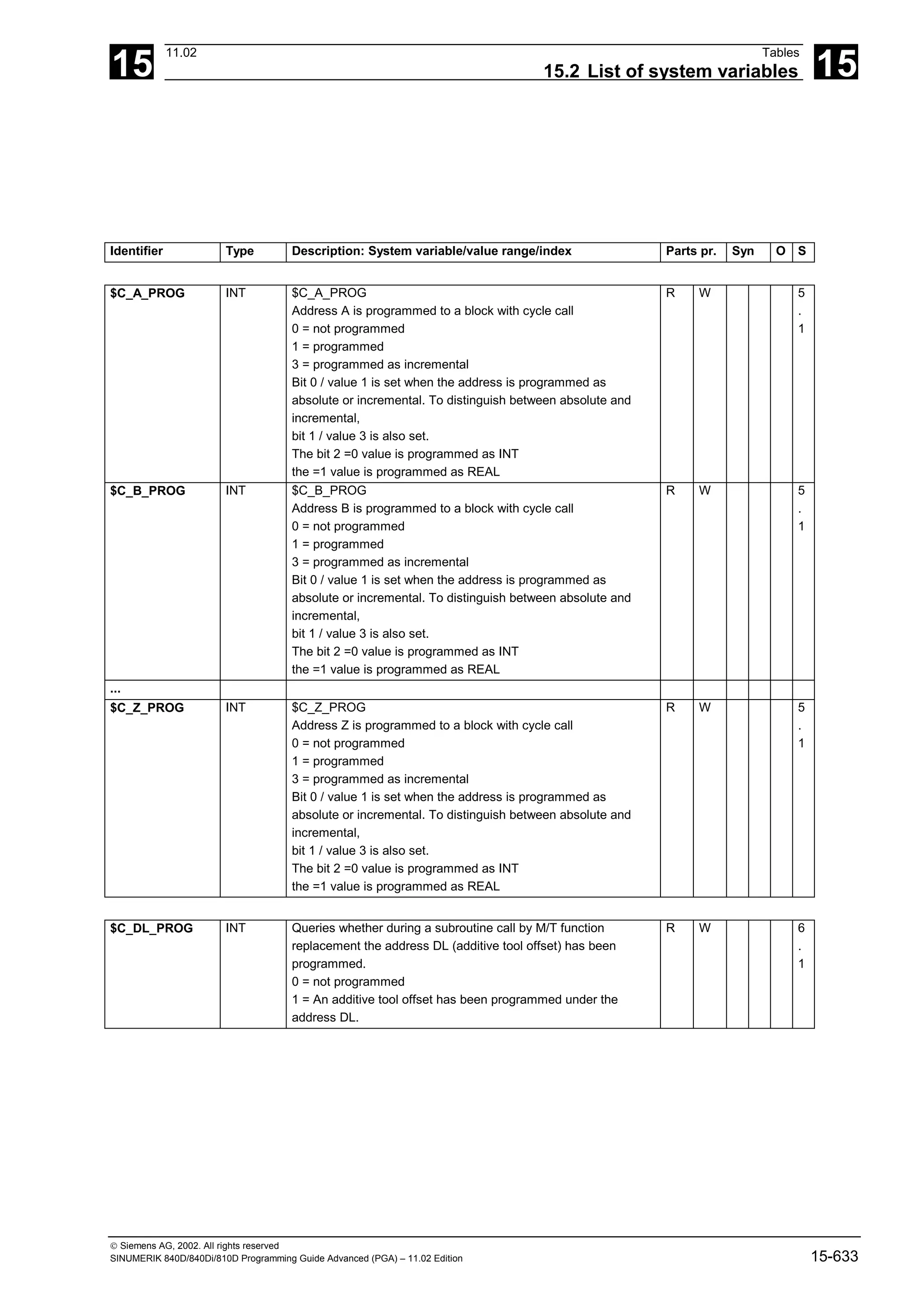
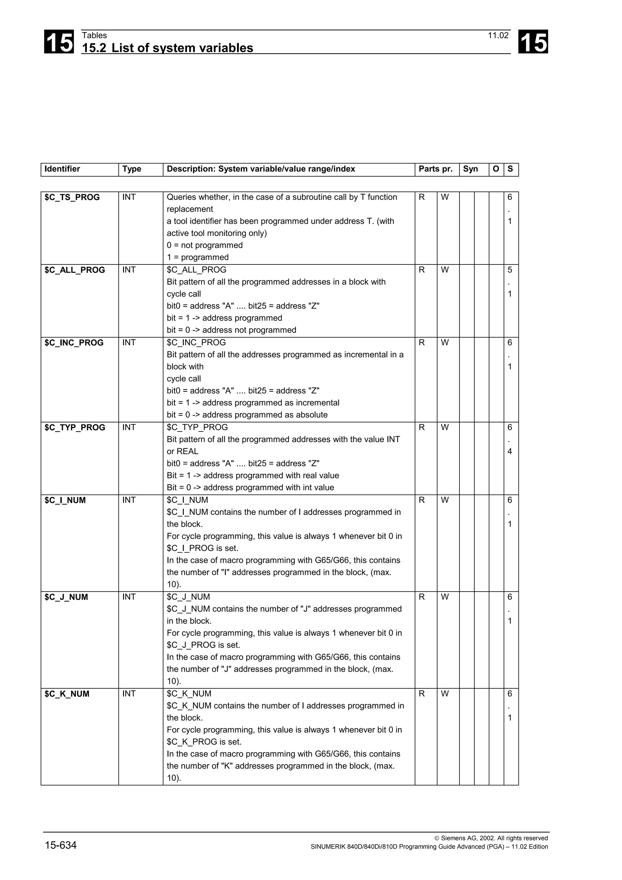
![15
11.02 Tables
15.2 List of system variables 15
Siemens AG, 2002. All rights reserved
SINUMERIK 840D/840Di/810D Programming Guide Advanced (PGA) – 11.02 Edition 15-635
Identifier Type Description: System variable/value range/index Parts pr. Syn O S
$C_I_ORDER INT $C_I_ORDER[]
Number of the IJK block, in which I has been programmed
For macro programming with G65/G66, up to 10 entries are
possible in the block with address I. These can be used to
evaluate the IJK sequence. A note is always made of which IJK
go together.
R W 6
.
4
$C_J_ORDER INT $C_J_ORDER[]
Number of the IJK block, in which J has been programmed
For macro programming with G65/G66, up to 10 entries are
possible in the block with address J. These can be used to
evaluate the IJK sequence.
from the parts program. A note is always made of which IJK go
together.
R W 6
.
4
$C_K_ORDER INT $C_K_ORDER[]
Number of the IJK block, in which K has been programmed
For macro programming with G65/G66, up to 10 entries are
possible in the block with address K. These can be used to
evaluate the IJK sequence from the parts program. A note is
always made of which IJK go together.
R W 6
.
4
$C_ME INT $C_ME
Address extension for address M in the case of a subroutine
call by M function
R W 6
.
1
$C_TE INT $C_TE
Address extension for address T in the case of a subroutine call
by T function
R W 6
.
1
$C_MACPAR REAL $MAC_PAR[n]
Macro variable in ISO2/3 mode programmed in the original
program with
#<Number>
The max. number of ISO macro parameters is 33
R W 6
.
3](https://image.slidesharecdn.com/fadaladvancedprogrammingmanual-220505063253/75/Fadal-Advanced-Programming-Manual-pdf-635-2048.jpg)
![15
Tables 11.02
15.2 List of system variables 15
Siemens AG, 2002. All rights reserved
15-636 SINUMERIK 840D/840Di/810D Programming Guide Advanced (PGA) – 11.02 Edition
15.2.23 System data
Identifier Type Description: System variable/value range/index Parts pr. Syn O S
$AN_SETUP_
TIME
REAL IF $AN_SETUP_TIME > 60000 GOTOF MARK01
Time since last power up of control with default values
(in minutes)
RS WS R W 6
.
1
$AN_POWERON_
TIME
REAL IF $AN_POWERON_TIME == 480 GOTOF MARK02
Time since last power-on of control
(in minutes)
RS WS R W 6
.
1
$AN_NCK_VER
SION
REAL NCK version:
NCK version: only the part of the floating-point number prior
to the decimal point is evaluated, the part after the decimal
point can contain identification for intermediate states within
development. The part prior to the decimal point contains
the official software version identifier of the NCK: For
example, if 20.00.00 is for the NCK version,
the value of the variable is 200000.0
compare OPI N/Y nckVersion
RS R 6
.
1
15.2.24 Frames 2
$P_UBFR FRAME $P_UBFR
1st base frame in channel activated after G500, G54..G599.
Corresponds to $P_CHBFR[0].
Axes: (geometry axis, channel axis, machine axis)
R W 4
$P_SETFRAME FRAME $P_SETFRAME
Current system frame for preset actual value memory and
scratching.
Axes: (geometry axis, channel axis, machine axis)
R W 6
.
1
$P_EXTFRAME FRAME $P_EXTFRAME
Current system frame for zero offset external.
Axes: (geometry axis, channel axis, machine axis)
R W 6
.
1
$P_PARTFRAME FRAME $P_PARTFRAME
Current system frame for TCARR and PAROT.
Axes: (geometry axis, channel axis, machine axis)
R 6
.
1
$P_TOOLFRAME FRAME $P_TOOLFRAME
Current system frame for TOROT and TOFRAME.
Axes: (geometry axis, channel axis, machine axis)
R 6
.
1
$P_WPFRAME FRAME $P_WPFRAME
Current system frame for part reference points.
Axes: (geometry axis, channel axis, machine axis)
R W 6
.
3
$P_CYCFRAME FRAME $P_CYCFRAME
Current system frame for cycles.
Axes: (geometry axis, channel axis, machine axis)
R W 6
.
3](https://image.slidesharecdn.com/fadaladvancedprogrammingmanual-220505063253/75/Fadal-Advanced-Programming-Manual-pdf-636-2048.jpg)
![15
11.02 Tables
15.2 List of system variables 15
Siemens AG, 2002. All rights reserved
SINUMERIK 840D/840Di/810D Programming Guide Advanced (PGA) – 11.02 Edition 15-637
Identifier Type Description: System variable/value range/index Parts pr. Syn O S
$P_CHBFRAME FRAME $P_CHBFRAME[n]
Current base frames in the channel.
Configurable via MD $MC_MM_NUM_BASE_FRAMES. The
dimension is checked on variable access.
Axes: (geometry axis, channel axis, machine axis)
R W 5
$P_NCBFRAME FRAME $P_NCBFRAME[n]
Current NCU base frames.
Configurable via MD
$MN_MM_NUM_GLOBAL_BASE_FRAMES.
The dimension is checked on variable access.
Axes: (geometry axis, channel axis, machine axis)
R W 5
$P_ACTBFRAME FRAME $P_ACTBFRAME
Current chained total basic frame
Axes: (geometry axis, channel axis, machine axis)
R 5
$P_BFRAME FRAME $P_BFRAME
Current 1st base frame in the channel. Corresponds to
$P_CHBFRAME[0].
Axes: (geometry axis, channel axis, machine axis)
R W 4
$P_IFRAME FRAME $P_IFRAME
Current settable frame
Axes: (geometry axis, channel axis, machine axis)
R W 2
$P_PFRAME FRAME $P_PFRAME
Current programmable frame
Axes: (geometry axis, channel axis, machine axis)
R W 2
$P_ACTFRAME FRAME $P_ACTFRAME
Current total frame
Axes: (geometry axis, channel axis, machine axis)
R 2
$P_UIFRNUM INT $P_UIFRNUM
Number of the active $P_UIFR
R 2
$P_NCBFRMASK INT $P_NCBFRMASK
Bit screenform is used for definition of the NCU global base
frames that are included in the calculation of the total base
frame.
R W 5
$P_CHBFRMASK INT $P_CHBFRMASK
Bit screenform is used for definition of channel-specific base
frames that are included in the calculation of the total base
frame.
R W 5](https://image.slidesharecdn.com/fadaladvancedprogrammingmanual-220505063253/75/Fadal-Advanced-Programming-Manual-pdf-637-2048.jpg)
![15
Tables 11.02
15.2 List of system variables 15
Siemens AG, 2002. All rights reserved
15-638 SINUMERIK 840D/840Di/810D Programming Guide Advanced (PGA) – 11.02 Edition
15.2.25 Tool data
Identifier Type Description: System variable/value range/index Parts pr. Syn O S
$P_AD REAL $P_AD[n]
Active tool offsets
n: Parameter number 1–31
n = 1-25 $TC_DP1 to $TC_DP25
n = 26 $TC_DPCE
n = 27 $TC_DPH
n = 28 $TC_DPV
n = 29 $TC_DPV3
n = 30 $TC_DPV4
n = 31 $TC_DPV5
R W 2
$P_ADT REAL $P_ADT[n]
With an active tool adapter, the transformed compensation
values of the tool adapter transformation are returned when
reading the values tool compensations are transformed
n: Parameter number 1–31
n = 1-25 $TC_DP1 to $TC_DP25
n = 26 $TC_DPCE
n = 27 $TC_DPH
n = 28 $TC_DPV
n = 29 $TC_DPV3
n = 30 $TC_DPV4
n = 31 $TC_DPV5
R W 6
.
1
$P_DLNO INT $P_DLNO
Active cumulative compensation number DL=0 - DL='max.';
'max'= value of
$MN_MM_MAX_SUMCORR_PER_CUTTEDGE
R 6
.
1
$P_TOOL INT $P_TOOL
Active tool cutting edge D0 - D'max.'; 'max'= value of
$MN_MM_MAX_CUTTING_EDGE_NO
R 2](https://image.slidesharecdn.com/fadaladvancedprogrammingmanual-220505063253/75/Fadal-Advanced-Programming-Manual-pdf-638-2048.jpg)
![15
11.02 Tables
15.2 List of system variables 15
Siemens AG, 2002. All rights reserved
SINUMERIK 840D/840Di/810D Programming Guide Advanced (PGA) – 11.02 Edition 15-639
Identifier Type Description: System variable/value range/index Parts pr. Syn O S
$P_TOOLNO INT $P_TOOLNO
Active tool number T0 - T32000; with active function 'flat D
number' T can have 8 digits
The command should generally not be used when magazine
management is active.
When magazine management is active, GETEXET should be
used instead.
(The programming is only ever reliable in a situation where
$MC_CUTTING_EDGE_DEFAULT=-1, > 0 applies.
The wrong tool number can be determined for
$MC_CUTTING_EDGE_DEFAULT=0, or =-2.
If programming takes place after programming D > 0, it is also
always reliable.
NOTICE: Especially for $MC_CUTTING_EDGE_DEFAULT=-
2, $P_TOOLNO
(the tool no. of the active tool with which the currently
effective D offset was being calculated) and GETEXET (the
changed tool) can return different tool numbers.
->also see $P_MTHSDC and documentation on the topic of
more than one tool holder/spindle.
R 2
$P_TOOLP INT $P_TOOLP
Last programmed tool number T0 - T32000 (for operation
without magazine management).
The command cannot be used when magazine management
is active.
When magazine management is active, GETSELT must be
used instead.
R 6
.
1
$P_TOOLL REAL $P_TOOLL[n]
Active total tool length
n: Length 1–3
R 2
$P_TOOLO REAL $P_TOOLO[n]
Active tool orientation.
n: Component 1–3
R 6
.
1
$AC_TOOLO_A
CT
REAL $AC_TOOLO_ACT[n]
Active setpoint orientation.
n: Component 1–3
RS R 6
.
4
$AC_TOOLO_E
ND
REAL $AC_TOOLO_END[n]
End orientation of the active block
n: Component 1–3
RS R 6
.
4
$AC_TOOLO_DI
FF
REAL $AC_TOOLO_DIFF
Residual angle of tool orientation in the active block
RS R 6
.
4
$VC_TOOLO REAL $VC_TOOLO[n]
Actual orientation
n: Component 1–3
RS R 6
.
4](https://image.slidesharecdn.com/fadaladvancedprogrammingmanual-220505063253/75/Fadal-Advanced-Programming-Manual-pdf-639-2048.jpg)
![15
Tables 11.02
15.2 List of system variables 15
Siemens AG, 2002. All rights reserved
15-640 SINUMERIK 840D/840Di/810D Programming Guide Advanced (PGA) – 11.02 Edition
Identifier Type Description: System variable/value range/index Parts pr. Syn O S
$VC_TOOLO_DI
FF
REAL $VC_TOOLO_DIFF
Angle between setpoint orientation and actual orientation
RS R 6
.
4
$VC_TOOLO_S
TAT
INT $VC_TOOLO_STAT
Status of the calculation of actual orientation
RS R 6
.
4
$P_TC INT $P_TC
Active tool carrier
R 6
.
1
$AC_TC INT $AC_TC
Active tool carrier
RS R 6
.
4
$P_TCANG REAL $P_TCANG[n]
Active angle of toolholder axis
n: Angle 1–2
R 5
$P_TCDIFF REAL $P_TCDIFF[n]
The difference between the calculated and the used angle of
a toolholder axis when incrementing (Hirth tooth system) the
angle
n: Angle 1–2
R 6
.
1
$P_TCSOL INT $P_TCSOL
Number of solutions when specifying the axis of rotation angle
of an orientable toolholder from a frame
With 0 to 2 solutions, the corresponding value
is returned.
With an infinite number of solutions, the return value is 3.
If the angles are specified (TCOABS), the number of solutions
is always 1.
R 6
.
1
$P_TCSTAT INT $P_TCSTAT
Specifies the status of an orientable toolholder.
The variable is bit-coded with the following significance:
0x1 The first rotary axis is available
0x2 The second rotary axis is available
0x4 The angles used for the calculation
come from an orientation in the frame direction
0x8 The angles used for the calculation
have been specified as absolute
0x10 The pole axis angle is indeterminate for
orientation in the frame direction
0x1000 Only the tool can be rotated (kinematics type T)
0x2000 Only the workpiece can be rotated (kinematics type
P)
0x4000 Tool and workpiece can be rotated
(kinematics type M)
Bits not designated here are currently unassigned.
R 6
.
4
$P_TOOLR REAL $P_TOOLR
Active tool radius (total)
R 2](https://image.slidesharecdn.com/fadaladvancedprogrammingmanual-220505063253/75/Fadal-Advanced-Programming-Manual-pdf-640-2048.jpg)
![15
11.02 Tables
15.2 List of system variables 15
Siemens AG, 2002. All rights reserved
SINUMERIK 840D/840Di/810D Programming Guide Advanced (PGA) – 11.02 Edition 15-641
Identifier Type Description: System variable/value range/index Parts pr. Syn O S
$P_TOOLND INT $P_TOOLND[t]
Number of cutting edges of tool t
t: Tool number 1–32000
R 4
$P_TOOLEXIST BOOL $P_TOOLEXIST[t]
Tool with T No. t exists
t: Tool number 1–32000
R 4
$P_D INT $P_D
Current D number in ISO_2-language mode
R 6
.
1
$P_H INT $P_H
Current H number in ISO_2-language mode
R 6
.
1
$A_TOOLMN INT $A_TOOLMN[t]
Magazine number of tool t
t: Tool number 1–32000
R 4
$A_TOOLMLN INT $A_TOOLMLN[t]
Magazine location number of tool t
t: Tool number 1–32000
R 4
$A_MYMN INT $A_MYMN[t]
Owner magazine number of the tool with T number t.
Result value = 0 = tool is not loaded (if $A_TOOLMN
> 0, then
manual tool).
Result value = -1 = tool management is not active
Result value = -2 = tool with T number t does not exist.
t: Tool number 1–32000
R 6
.
1
$A_MYMLN INT $A_MYMLN[t]
Owner magazine location number of the tool with T number t.
Result value = 0 = tool is not loaded (if $A_TOOLMLN > 0,
then
manual tool).
Result value = -1 = tool management is not active
Result value = -2 = tool with T number t does not exist.
t: Tool number 1–32000
R 6
.
1
$A_MONIFACT REAL $A_MONIFACT
Factor for tool length monitoring
R WS R W 4](https://image.slidesharecdn.com/fadaladvancedprogrammingmanual-220505063253/75/Fadal-Advanced-Programming-Manual-pdf-641-2048.jpg)
![15
Tables 11.02
15.2 List of system variables 15
Siemens AG, 2002. All rights reserved
15-642 SINUMERIK 840D/840Di/810D Programming Guide Advanced (PGA) – 11.02 Edition
Identifier Type Description: System variable/value range/index Parts pr. Syn O S
$P_TOOLNG INT $P_TOOLNG
Number of defined tool groups assigned to the channel
OPI module type = TM
R 6
.
1
$P_TOOLNT INT $P_TOOLNT
Number of defined tools assigned to the channel
OPI module type = TV
R 6
.
1
$P_TOOLT INT $P_TOOLT[i]
i-th tool number T
OPI module type = TV
i= 1,..., $P_TOOLNT
R 6
.
1
$P_TOOLD INT $P_TOOLD[t,i]
i-th D-no of the tool with T number t; i=1,2...
if t is the value of a non-defined tool, -2 is returned
If i is a value outside the permitted range, 0 is returned.
OPI module type = TO
t = 1, ...., 32000
i = 1,......., $P_TOOLND
R 6
.
1
$P_USEKT INT $P_USEKT (= USE Kind of Tool)
Is a bit-coded value
All the tools whose parameter $TC_TP11 has set one of the bits
of $P_USEKT,
are available to the following tool changes. The value zero
has the same content
as 'all bits set'
OPI module = C/S
R W 6
.
1
$P_TOOLNDL INT $P_TOOLNDL[t,d]
Number of DL offsets of the D offset given by T number t and
D number d
>0 Number of DL offsets
0 no DL offset for this D offset
-1 sum offset function not active
-2 t is the value of a non-defined tool
-3 d is the value of a non-defined D offset
OPI module type = TO memory; TO unit
t = 1, ...., 32000
d = 1,......., 32000
R 6
.
1](https://image.slidesharecdn.com/fadaladvancedprogrammingmanual-220505063253/75/Fadal-Advanced-Programming-Manual-pdf-642-2048.jpg)
![15
11.02 Tables
15.2 List of system variables 15
Siemens AG, 2002. All rights reserved
SINUMERIK 840D/840Di/810D Programming Guide Advanced (PGA) – 11.02 Edition 15-643
15.2.26 Magazines
Identifier Type Description: System variable/value range/index Parts pr. Syn O S
$P_MAGN INT $P_MAGN
Number of defined magazines assigned to the channel
> 0 successful read access
0 no magazines defined
-1 TMMG not active
OPI module = TM
R 6
.
1
$P_MAG INT $P_MAG[ i ]
i-th magazine number
> 0 successful read access
0 i is outside the permitted range
-1 TMMG not active
OPI module = TM
i= 1,..., $P_MAGN
R 6
.
1
$P_MAGNDIS INT P_MAGNDIS[ n, m ]
Number of magazines interconnected with location m of the
internal magazine n.
> 0 successful read access
0 no magazine interconnected with the buffer location
-1 TMMG not active
-2 n is not the number of an internal magazine
-3 m is not the number of an internal magazine location
OPI module = TPM
n= must be the number of the buffer magazine or of the
loading magazine
m= 1,..., max. number of a location in the internal magazine
mentioned
R 6
.
1
$P_MAGDISS INT P_MAGDISS[ l, i ]
Number of the i-th magazine interconnected with location l
of the buffer magazine.
> 0 successful read access
0 i is outside the permitted range
-1 TMMG not active
-2 m is not the number of a buffer location
-3 no buffer magazine defined
OPI module = TPM
l= 1,..., max. number of a location in the buffer magazine
i= 1,..., $P_MAGNDIS[ no. of the buffer magazine, refLoc ]
R 6
.
1](https://image.slidesharecdn.com/fadaladvancedprogrammingmanual-220505063253/75/Fadal-Advanced-Programming-Manual-pdf-643-2048.jpg)
![15
Tables 11.02
15.2 List of system variables 15
Siemens AG, 2002. All rights reserved
15-644 SINUMERIK 840D/840Di/810D Programming Guide Advanced (PGA) – 11.02 Edition
Identifier Type Description: System variable/value range/index Parts pr. Syn O S
$P_MAGDISL INT P_MAGDISL[ l, i ]
Number of the i-th magazine interconnected with location l of
the loading magazine.
> 0 successful read access
0 i is outside the permitted range
-1 TMMG not active
-2 m is not the number of a loading magazine location
-3 no loading magazine defined
OPI module = TPM
l= 1,..., max. number of a location in the loading magazine
i= 1,..., $P_MAGNDIS[ no. of the loading magazine, refLoc ]
R 6
.
1
$P_MAGNS INT $P_MAGNS
Number of spindle locations / toolholder locations in the buffer
assigned to the channel.
> 0 successful read access
0 no spindle locations defined
-1 TMMG not active
-3 no buffer magazine defined
R 6
.
1
$P_MAGS INT $P_MAGS[ n ]
nth number of the spindle / of the toolholder in the buffer
> 0 successful read access
0 n is outside the permitted range
-1 TMMG not active
-3 no buffer magazine defined
n= 1,..., max. toolholder number
R 6
.
1
$P_MAGNREL INT $P_MAGNREL[ n ]
Number of the buffer assigned to the spindle number /
toolholder number n
> 0 successful read access
0 spindle location has no buffer location assigned
-1 TMMG not active
-2 n is not the number of a spindle location
-3 no buffer magazine defined
n= 1,..., max. toolholder number
R 6
.
1
$P_MAGREL INT P_MAGREL[ n, m ]
m-th buffer number of the n-th spindle number / toolholder
number
> 0 successful read access
0 m is outside the permitted range
-1 TMMG not active
-2 n is not the number of a spindle location
-3 no buffer magazine defined
n= 1,..., max. toolholder number
m= 1,..., $P_MAGNREL
R 6
.
1](https://image.slidesharecdn.com/fadaladvancedprogrammingmanual-220505063253/75/Fadal-Advanced-Programming-Manual-pdf-644-2048.jpg)
![15
11.02 Tables
15.2 List of system variables 15
Siemens AG, 2002. All rights reserved
SINUMERIK 840D/840Di/810D Programming Guide Advanced (PGA) – 11.02 Edition 15-645
Identifier Type Description: System variable/value range/index Parts pr. Syn O S
$P_MAGNH INT $P_MAGNH
Number of defined magazine location type hierarchies assigned
to the channel.
> 0 successful read access
0 no location type hierarchies are defined
-1 TMMG not active
OPI module = TT
R 6
.
1
$P_MAGNHLT INT $P_MAGNHLT[ n ]
Number of defined location types in the nth defined hierarchy
> 0 successful read access
0 n is outside the defined range
-1 TMMG not active
OPI module = TT
n= 1,..., $P_MAGNH
R 6
.
1
$P_MAGHLT INT P_MAGHLT[ n, m ]
m-th location type of hierarchy n; n= 1,..., $P_MAGNH; m= 1,...,
$P_MAGNHLT
> 0 successful read access
0 m is outside the defined range
-1 TMMG not active
-2 hierarchy n has no defined location types
OPI module = TT
n= 1,..., $P_MAGNH
m= 1,..., $P_MAGNHLT
R 6
.
1
$P_MAGNA INT $P_MAGNA
Number of defined adapters assigned to the channel
> 0 successful read access
0 no adapters defined
-1 TMMG or 'Adapter' function not active
OPI module = AD
R 6
.
1
$P_MAGA INT $P_MAGA[ i ]
i-th adapter number
> 0 successful read access
0 i is outside the permitted range
-1 TMMG or 'Adapter' function not active
OPI module = AD
i= 1,..., $P_MAGNA
R 6
.
1
$P_MTHSDC INT $P_MTHSDC
Master toolholder no. or master spindle no. relative to that of the
active tool
for
which the next D offset selection is specified.
> 0 successful read access
0 No master toolholder or master spindle available.
The next D offset works with T0.
-1 TMMG not available
R 6
.
4](https://image.slidesharecdn.com/fadaladvancedprogrammingmanual-220505063253/75/Fadal-Advanced-Programming-Manual-pdf-645-2048.jpg)
![15
Tables 11.02
15.2 List of system variables 15
Siemens AG, 2002. All rights reserved
15-646 SINUMERIK 840D/840Di/810D Programming Guide Advanced (PGA) – 11.02 Edition
Identifier Type Description: System variable/value range/index Parts pr. Syn O S
$AC_MONMIN REAL $AC_MONMIN
Ratio between tool monitoring actual value and setpoint.
Threshold for tool search strategy "load only tools
with actual value greater than threshold"
R WS R W 6
.
1
$P_VDITCP INT $P_VDITCP[n]
Available parameters for magazine management on VDI
interface
n: Index 1–3
R W 2
$A_DNO INT $A_DNO[i]
Read a D number defined by the PLC via VDI interface
i: Index 1–9 for table location in D number table
R 4
$P_ATPG REAL $P_ATPG[n]
Current tool-related grinding data
n: Parameter number 1–9
R W 2
$P_TOOLENV STRING $P_TOOLENV[i]
Returns the name of the tool environment stored under
(internal)
index i. If i refers to a non-defined data block, the zero string
is returned.
If index i is invalid, in other words, if i is less than 1 or more
than the maximum number of data blocks for tool
environments
($MN_MM_NUM_TOOLENV), an alarm is output.
A maximum number of tool environments is configurable via
MD $MN_MM_NUM_TOOLENV.
2nd dimension for TYPE_STRING is automatically
MAXSTRINGLEN
R 6
.
3
$P_TOOLENVN INT $P_TOOLENVN
Indicates the number of defined data blocks for describing
tool environments.
R 6
.
3
$P_AP REAL $P_AP
Programmed angle for polar coordinates
R 6
.
1
15.2.27 Programmed geometry axis values
$P_AXN1 AXIS $P_AXN1
Current address of the geometry axis - abscissa
R 3
$P_AXN2 AXIS $P_AXN2
Current address of the geometry axis - ordinate
R 3](https://image.slidesharecdn.com/fadaladvancedprogrammingmanual-220505063253/75/Fadal-Advanced-Programming-Manual-pdf-646-2048.jpg)
![15
11.02 Tables
15.2 List of system variables 15
Siemens AG, 2002. All rights reserved
SINUMERIK 840D/840Di/810D Programming Guide Advanced (PGA) – 11.02 Edition 15-647
Identifier Type Description: System variable/value range/index Parts pr. Syn O S
$P_AXN3 AXIS $P_AXN3
Current address of the geometry axis - applicate
R 3
$P_ACTGEOAX AXIS $P_ACTGEOAX[1]
Current geometry axis assignment, dependent on plane
Returns the current geometry axis assignment programmed
with
geometry axis(1,X,2,Y,3,Z)
Array index 1–3 for 1st to 3rd geometry axis
n: Number of input 1 - ...
R 4
15.2.28 G groups
$P_GG INT $P_GG[n]
Current G function of a G group (index as PLC interface)
n: Number of the G group
R 2
$P_EXTGG INT $P_EXTGG[n]
Can only be used in Siemens mode:
Current G function of a G group with external NC languages
(index as PLC interface)
n: Number of the G group
R 5
$A_GG INT $A_GG[n]
Read current G function of a G group from SA (index like PLC
interface)
n: Number of the G group
R 5
15.2.29 Programmed values
$P_SEARCH BOOL $P_SEARCH
Block search is active if TRUE (1)
R 2
$P_SEARCH1 BOOL $P_SEARCH1
Block search with calculation is active if TRUE (1)
R 2
$P_SEARCH2 BOOL $P_SEARCH2
The last selected search type was block search without
calculation, if
TRUE (1)
R 2](https://image.slidesharecdn.com/fadaladvancedprogrammingmanual-220505063253/75/Fadal-Advanced-Programming-Manual-pdf-647-2048.jpg)
![15
Tables 11.02
15.2 List of system variables 15
Siemens AG, 2002. All rights reserved
15-648 SINUMERIK 840D/840Di/810D Programming Guide Advanced (PGA) – 11.02 Edition
Identifier Type Description: System variable/value range/index Parts pr. Syn O S
$P_SEARCHL INT R1 = $P_SEARCHL
Returns the last selected search type:
(coding analogous to PI service _N_FINDBL)
0 : No block search
1 : Block search without calculation
2 : Block search with calculation on contour
3 : Reserved
4 : Block search with calculation at end of block position
5 : Block search in extended program test
R 5
$P_SUBPAR BOOL $P_SUBPAR[n]
Query whether during subroutine call with parameter transfer
parameter n
was actually programmed (TRUE) or whether the system has
set a default parameter (FALSE).
n: Parameter number 1 to n corresponding to the definition in
the PROC instruction
R 5
$P_CTABDEF BOOL $P_CTABDEF
Definition of curve tables is active if TRUE (1)
R 4
$P_MC INT $P_MC
Status of modal subprogram call
FALSE (0) -> Subprogram call not modal
TRUE (1) -> Subprogram call modal
R 2
$P_REPINF INT $P_REPINF
Status info for repositioning with REPOS command
(0) -> Repositioning with REPOS not possible for following
reasons
- Call is not executed in an ASUB
- Call is executed in an ASUB, which was started in the reset
state JOG mode
- Call is executed in an ASUB, which was started in
JOG mode
(1) -> Repositioning with REPOS possible
R 4
$P_SIM BOOL $P_SIM
Simulation runs if TRUE (1)
R 2](https://image.slidesharecdn.com/fadaladvancedprogrammingmanual-220505063253/75/Fadal-Advanced-Programming-Manual-pdf-648-2048.jpg)
![15
11.02 Tables
15.2 List of system variables 15
Siemens AG, 2002. All rights reserved
SINUMERIK 840D/840Di/810D Programming Guide Advanced (PGA) – 11.02 Edition 15-649
Identifier Type Description: System variable/value range/index Parts pr. Syn O S
$P_DRYRUN BOOL $P_DRYRUN
Dry run on if TRUE, else FALSE
R 2
$P_OFFN REAL $P_OFFN
Programmed offset contour normal
R 5
.
1
$PI REAL $PI
Circle constant PI = 3.1415927
R 2
$P_PROG_EVE
NT
INT The system variable $P_PROG_EVENT can be used to query
whether the program was implicitly activated by an event
configured by $MC_PROG_EVENT_MASK or by
$MN_SEARCH_RUN_MODE. $P_PROG_EVENT returns an
integer value between 0 and 5 with the following significance:
0 : explicit activation via NC Start or ASUB Start over the
VDI or ASUB interface
1 : Implicit activation via event "Parts program start”
2 : Implicit activation via event "Parts program end"
3 : Implicit activation via event "Operator panel front reset"
4 : Implicit activation via event "Booting"
5 : Implicit activation subsequent to last action block display
after block search
R 6
.
1
$P_PROGPATH STRING PCALL ($P_PROGPATH << _N_MYSUB_SPF)
Call a subprogram from the current directory
Example: The current directory is
/_N_WKS_DIR/_N_SHAFT_DIR/.
The above call starts the subprogram
/_N_WKS_DIR/_N_SHAFT%_DIR/_N_MYSUB_SPF.
2nd dimension for TYPE_STRING is automatically
MAXSTRINGLEN
R 3
$P_PROG STRING $P_PROG[0]
Returns the program name of the program in program level 0 =
main program name,
in string variable NAME
Defines the program level from which the program name is to
be read.
2nd dimension for TYPE_STRING is automatically
MAXSTRINGLEN
R 5
.
1
$P_STACK INT $P_STACK
Returns the program level in which a parts program is active.
progLevel = $P_STACK , writes in the integer variable the
number of the current program level
802S/C: Range of values = [0,5]
R 5
.
1](https://image.slidesharecdn.com/fadaladvancedprogrammingmanual-220505063253/75/Fadal-Advanced-Programming-Manual-pdf-649-2048.jpg)
![15
Tables 11.02
15.2 List of system variables 15
Siemens AG, 2002. All rights reserved
15-650 SINUMERIK 840D/840Di/810D Programming Guide Advanced (PGA) – 11.02 Edition
Identifier Type Description: System variable/value range/index Parts pr. Syn O S
$P_PATH STRING Application Reading the path name of the calling program.
$P_PATH[0] returns the directory of the current main program,
for example,
"/_N_WKS_DIR/_N_WELLE_WPD"
The variable is used, for example, to store a parts program
generated with WRITE in the same directory as the calling
program:
PROC MYPRINTSUB
DEF INT ERROR
WRITE (ERROR, $P_PATH[$P_STACK - 1] <<
"_N_LIST_MPF", "X10 Y20")
If the subroutine was called from the shaft (WELLE) workpiece
directory, a new file is generated in
/_N_WKS_DIR/_N_WELLE_WPD/_N_LIST_MPF.
Defines the program level from which the program path is to be
read
2nd dimension for TYPE_STRING is automatically
MAXSTRINGLEN
R 5
.
1
$P_ACTID BOOL $P_ACTID[n]
Modal synchronized action with ID n active if TRUE
n: 1–16
R 2](https://image.slidesharecdn.com/fadaladvancedprogrammingmanual-220505063253/75/Fadal-Advanced-Programming-Manual-pdf-650-2048.jpg)
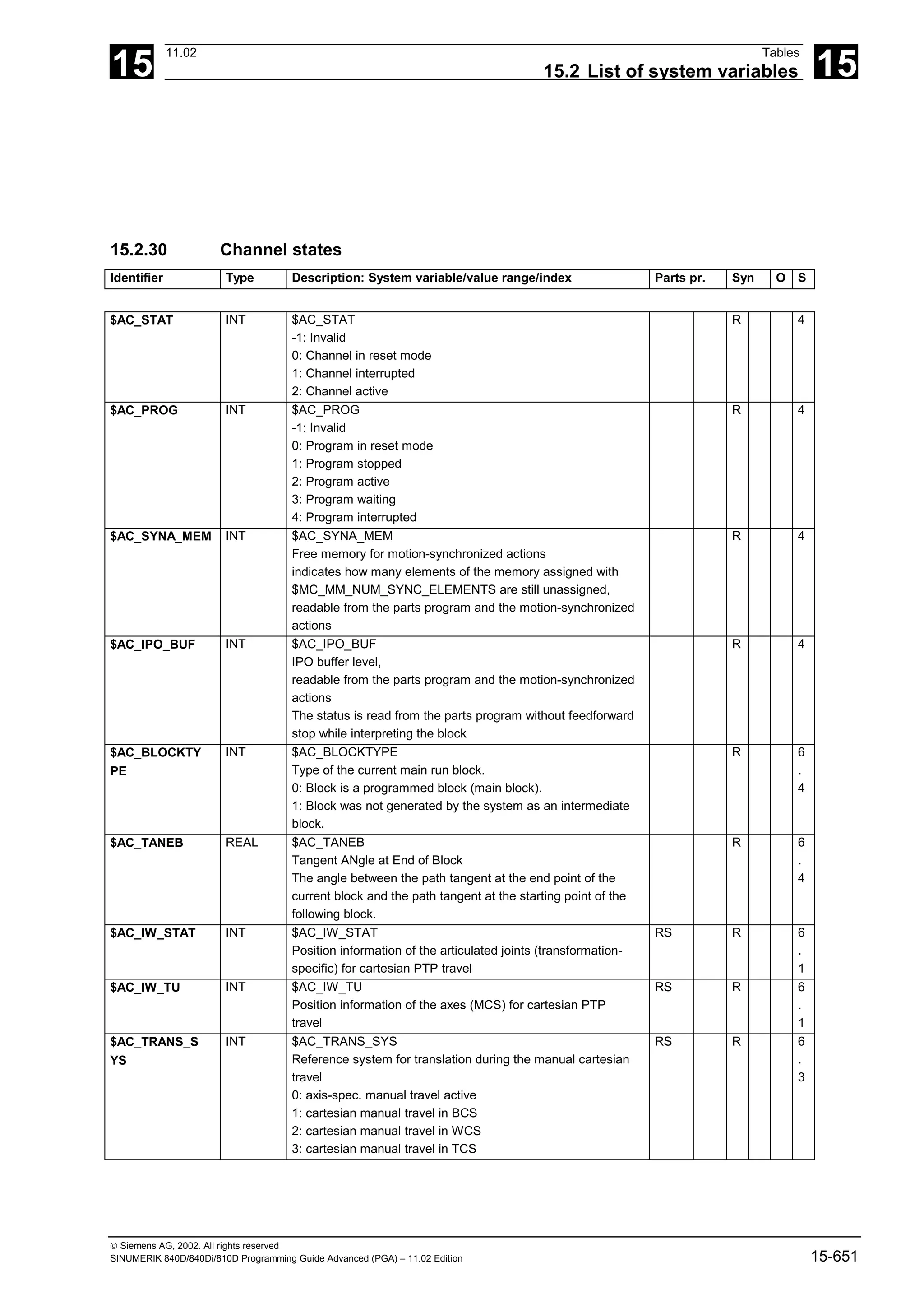
![15
Tables 11.02
15.2 List of system variables 15
Siemens AG, 2002. All rights reserved
15-652 SINUMERIK 840D/840Di/810D Programming Guide Advanced (PGA) – 11.02 Edition
Identifier Type Description: System variable/value range/index Parts pr. Syn O S
$AC_JOG_COO
RD
INT $AC_JOG_COORD
Setting the coordinate system for manual travel
0: manual travel in WCS
1: manual travel in SZS
R W 6
.
4
$AC_ROT_SYS INT $AC_ROT_SYS
Reference system for orientation during the manual
cartesian travel
0: axis-spec. manual travel active
1: cartesian manual travel in BCS
2: cartesian manual travel in PCS
3: cartesian manual travel in TCS
RS R 6
.
3
$A_PROBE INT $A_PROBE[1]: Status of first probe
$A_PROBE[2]: Status of second probe
0 => not deflected
1 => deflected
n: Number of probe
RS R 4
$AC_MEA INT $AC_MEA[n]
Probe has been triggered if TRUE (1)
n: Number of probe
1 - MAXNUM_PROBE
R 2
$AC_TRAFO INT $AC_TRAFO
Code number of the active transformation
corresponding to machine data $MC_TRAFO_TYPE_n
RS R 3
$P_TRAFO INT $P_TRAFO
Code number of the programmed transformation
corresponding to machine data $MC_TRAFO_TYPE_n
R 6
.
1
$AC_TRAFO_P
AR
REAL $AC_TRAFO_PAR[n]
Parameter of the active transformation
n: Number of the parameter
RS R 6
.
1
$P_TRAFO_PAR REAL $P_TRAFO_PAR[n]
Parameter of the programmed transformation
n: Number of the parameter
R 6
.
1
$AC_TRAFO_P
ARSET
INT $AC_TRAFO_PARSET
Number of the active transformation record
Variable is '0' if no transformer active
RS R 6
.
3
$P_TRAFO_PA
RSET
INT $P_TRAFO_PARSET
Number of the programmed transformation record
Variable is '0' if no transformer active
R 6
.
3
$AC_LIFTFAST INT $AC_LIFTFAST
Information about execution of liftfast.
0: Initial state.
1: Liftfast has been executed.
At the start of the liftfast operation, the NC sets the value
of the variable internally to "1".
The evaluating program (if available) must reset the variable
to its initial setting ($AC_LIFTFAST=0) to enable a
subsequent liftfast to be detected.
RS WS R W 4](https://image.slidesharecdn.com/fadaladvancedprogrammingmanual-220505063253/75/Fadal-Advanced-Programming-Manual-pdf-652-2048.jpg)
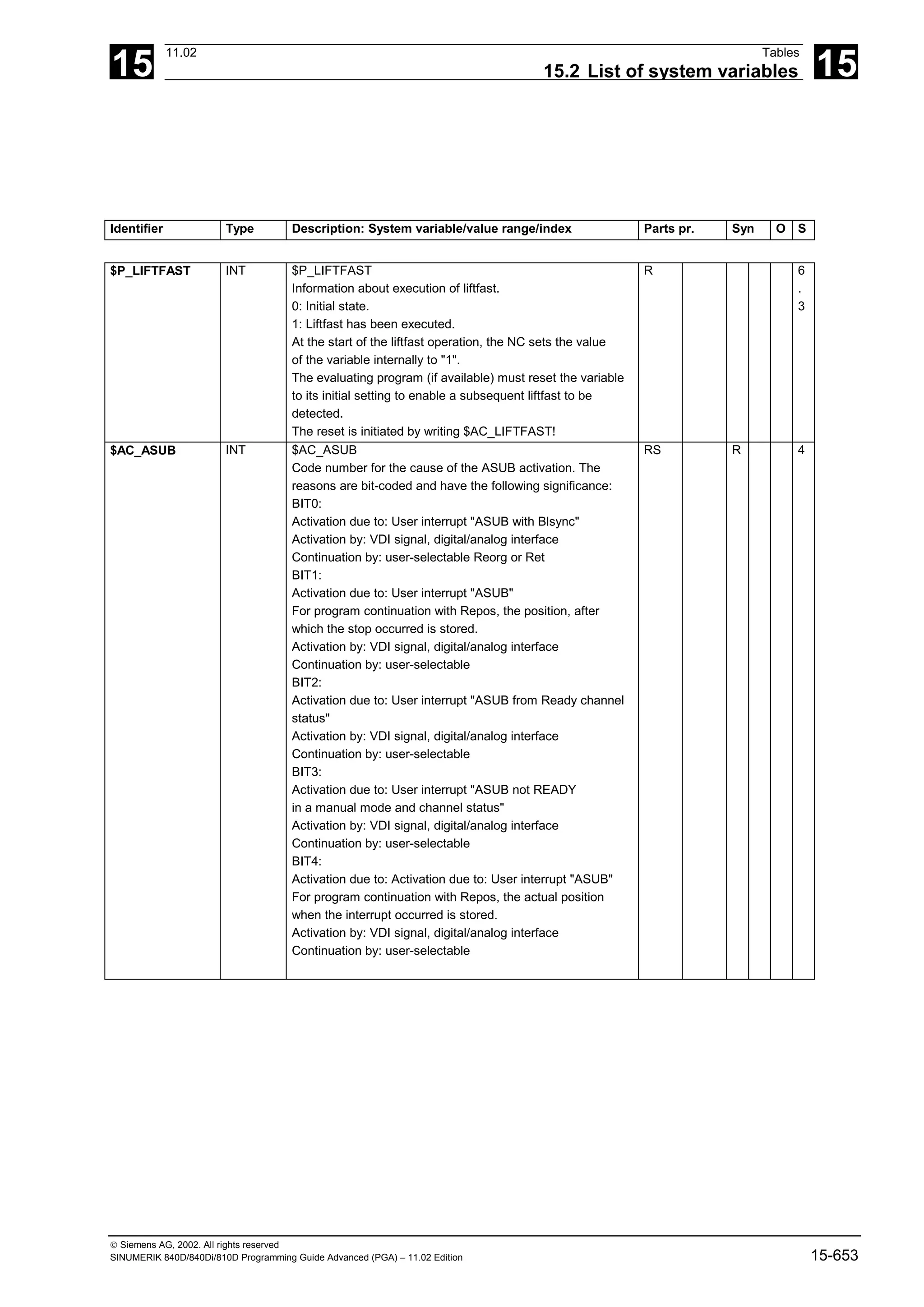
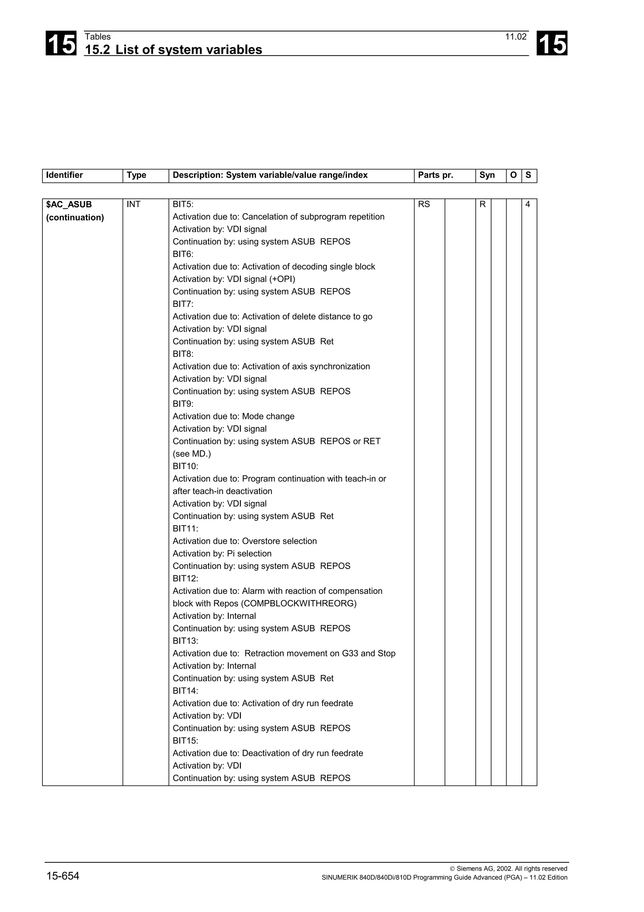
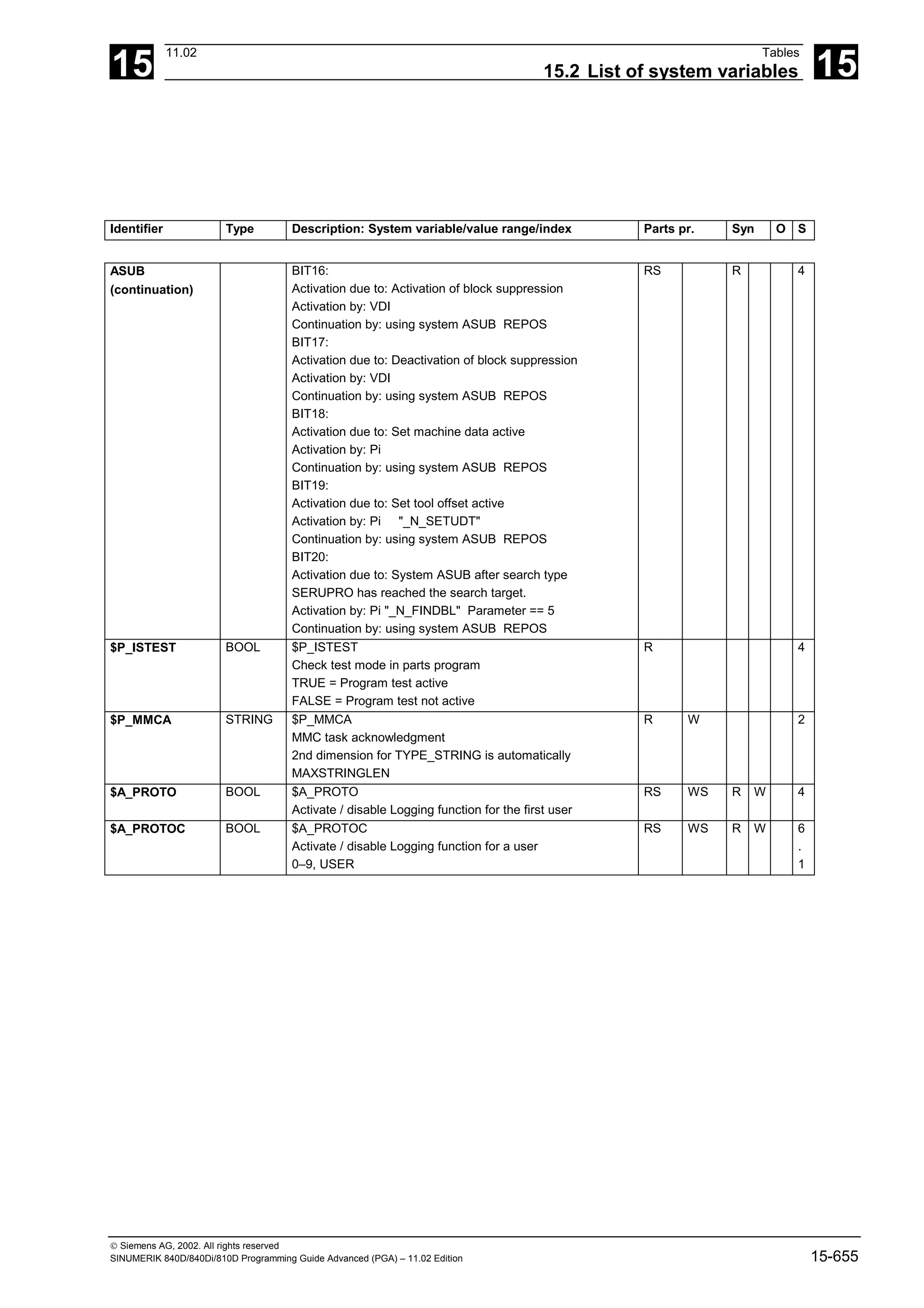
![15
Tables 11.02
15.2 List of system variables 15
Siemens AG, 2002. All rights reserved
15-656 SINUMERIK 840D/840Di/810D Programming Guide Advanced (PGA) – 11.02 Edition
15.2.31 Synchronized actions
Identifier Type Description: System variable/value range/index Parts pr. Syn O S
$AC_FIFO1 REAL $AC_FIFO1[n]
FIFO for motion-synchronized actions and cyclic
measurements
n: Parameter number 0 - max. FIFO element
Special meaning:
n=0: On write accesses with index 0, a new value is stored
in the FIFO,
On read accesses with index 0, the oldest element is
read and deleted from the FIFO
n=1: Read access to oldest element
n=2: Read access to latest element
n=3: Sum of all the elements located in the FIFO when in MD
$MC_MM_MODE_FIFO, bit0 is set
n=4: Read access to current number of FIFO elements
n=5-m: Read access to individual FIFO elements
5 is the oldest element
6 is the second-oldest, etc.
RS W R W + 4
$AC_FIFO2 REAL $AC_FIFO2[n]
FIFO for motion-synchronized actions and cyclic
measurements
n: Parameter number 0 - max. FIFO element
Special meaning:
n=0: On write accesses with index 0, a new value is stored
in the FIFO,
On read accesses with index 0, the oldest element is
read and deleted from the FIFO
n=1: Read access to oldest element
n=2: Read access to latest element
n=3: Sum of all the elements located in the FIFO when in MD
$MC_MM_MODE_FIFO, bit0 is set
n=4: Read access to current number of FIFO elements
n=5-m: Read access to individual FIFO elements
5 is the oldest element
6 is the second-oldest, etc.
RS W R W + 4
...
$AC_FIFO10 REAL $AC_FIFO10[n]
as $AC_FIFO01 ...
RS W R W + 4](https://image.slidesharecdn.com/fadaladvancedprogrammingmanual-220505063253/75/Fadal-Advanced-Programming-Manual-pdf-656-2048.jpg)
![15
11.02 Tables
15.2 List of system variables 15
Siemens AG, 2002. All rights reserved
SINUMERIK 840D/840Di/810D Programming Guide Advanced (PGA) – 11.02 Edition 15-657
15.2.32 I/Os
Identifier Type Description: System variable/value range/index Parts pr. Syn O S
$A_IN BOOL $A_IN[n]
Digital input NC
n: Number of input 1 - ...
The max. input number results from MD
$MN_FASTIO_DIG_NUM_INPUTS
RS R 2
$A_OUT BOOL $A_OUT[n]
Digital output NC
n: Number of output 1 - ...
The max. input number results from MD
$MN_FASTIO_DIG_NUM_OUTPUTS
RS W R W 2
$A_INA REAL $A_INA[n]
Analog input NC
n: Number of input 1 - ...
The max. input number results from MD
$MN_FASTIO_ANA_NUM_INPUTS
RS R 2
$A_OUTA REAL $A_OUTA[n]
Analog output NC When writing, the value does not become
active until the next IPO cycle at which point it is read back.
n: Number of output 1 - ...
The max. input number results from MD
$MN_FASTIO_ANA_NUM_OUTPUTS
RS W R W 2
$A_INCO BOOL $A_INCO[n]
Comparator input
n: Number of output 1 - ...
The max. input number results from the MD
RS R 2
15.2.33 Reading and writing PLC variables
$A_DBB INT $A_DBB[n]
Read/write data byte (8 bits) from/to PLC
n: Position offset within I/O area 0 - ...
RS W R W + 4
$A_DBW INT $A_DBW[n]
Read/write data word (16 bits) from/to PLC
n: Position offset within I/O area 0 - ...
RS W R W + 4
$A_DBD INT $A_DBD[n]
Read/write double data word (32 bits) from/to PLC
n: Position offset within I/O area 0 - ...
RS W R W + 4
$A_DBR REAL $A_DBR[n]
Read/write Real data (32 bits) from/to PLC
n: Position offset within I/O area 0 - ...
RS W R W + 4](https://image.slidesharecdn.com/fadaladvancedprogrammingmanual-220505063253/75/Fadal-Advanced-Programming-Manual-pdf-657-2048.jpg)
![15
Tables 11.02
15.2 List of system variables 15
Siemens AG, 2002. All rights reserved
15-658 SINUMERIK 840D/840Di/810D Programming Guide Advanced (PGA) – 11.02 Edition
15.2.34 NCU link
Identifier Type Description: System variable/value range/index Parts pr. Syn O S
$A_DLB INT $A_DLB[n]
Read/write data byte (8 bits) from/to NCU link
n: Position offset within the link memory area 0 - ...
RS W R W + 5
$A_DLW INT $A_DLW[n]
Read/write data word (16 bits) from/to NCU link
n: Position offset within the link memory area 0 - ...
synchronized with main run
RS W R W + 5
$A_DLD INT $A_DLD[n]
Read/write data double word (32 bits) from/to NCU link
n: Position offset within the link memory area 0 - ...
synchronized with main run
RS W R W + 5
$A_DLR REAL $A_DLR[n]
Read/write Real data (32 bits) from/to NCU link
n: Position offset within the link memory area 0 - ...
synchronized with main run
RS W R W + 5
$A_LINK_TRAN
S_RATE
INT $A_LINK_TRANS_RATE
Number of bytes that can still be transferred via NCU link
Communication in the current IPO cycle.
R 5
15.2.35 Direct PLC I/O
$A_PBB_IN INT $A_PBB_IN[n]
Read data byte (8 bits) directly from PLC I/O
n: Position offset within PLC input area 0 - ...
RS R 5
$A_PBW_IN INT $A_PBW_IN[n]
Read data word (16 bits) directly from PLC I/O
n: Position offset within PLC input area 0 - ...
RS R 5
$A_PBD_IN INT $A_PBD_IN[n]
Read data double word (32 bits) directly from PLC I/O
n: Position offset within PLC input area 0 - ...
RS R 5
$A_PBR_IN REAL $A_PBR_IN[n]
Read Real data (32 bits) directly from PLC I/O
n: Position offset within PLC input area 0 - ...
RS R 6
.
1](https://image.slidesharecdn.com/fadaladvancedprogrammingmanual-220505063253/75/Fadal-Advanced-Programming-Manual-pdf-658-2048.jpg)
![15
11.02 Tables
15.2 List of system variables 15
Siemens AG, 2002. All rights reserved
SINUMERIK 840D/840Di/810D Programming Guide Advanced (PGA) – 11.02 Edition 15-659
Identifier Type Description: System variable/value range/index Parts pr. Syn O S
$A_PBB_OUT INT $A_PBB_OUT[n]
Write data byte (8 bits) directly to PLC I/O
n: Position offset within PLC output area 0 - ...
synchronized with main run
RS W R W 5
$A_PBW_OUT INT $A_PBW_OUT[n]
Write data word (16 bits) directly to PLC I/O
n: Position offset within PLC output area 0 - ...
synchronized with main run
RS W R W 5
$A_PBD_OUT INT $A_PBD_OUT[n]
Write data double word (32 bits) directly to PLC I/O
n: Position offset within PLC output area 0 - ...
synchronized with main run
RS W R W 5
$A_PBR_OUT REAL $A_PBR_OUT[n]
Write Real data (32 bits) directly to PLC I/O
n: Position offset within PLC output area 0 - ...
synchronized with main run
RS W R W 5
$C_IN BOOL $C_IN[n]
Signal from PLC to Cycle
reserved for SIEMENS applications
n: Number of input 1 - ...
RS R 6
.
1
$C_OUT BOOL $C_OUT[n]
Signal from Cycle to PLC
reserved for SIEMENS applications
n: Number of output 1 - ...
RS W R W 6
.
1
15.2.36 Tool management
These system variables have value –1 if no tool management command is active at time of reading.
$AC_TC_CMDT INT $AC_TC_CMDT
Trigger variable: $AC_TC_CMDT (CoMmandTrigger) then
always takes on the value 1 for an interpolation cycle when a
new magazine management command is output to the PLC.
RS R 6
.
1
$AC_TC_ACKT INT $AC_TC_ACKT
Trigger variable: $AC_TC_ACKT (ACKnowledgeTrigger) then
always takes on a value of 1 for an interpolation cycle
when the PLC acknowledges a tool management command.
RS R 6
.
1](https://image.slidesharecdn.com/fadaladvancedprogrammingmanual-220505063253/75/Fadal-Advanced-Programming-Manual-pdf-659-2048.jpg)
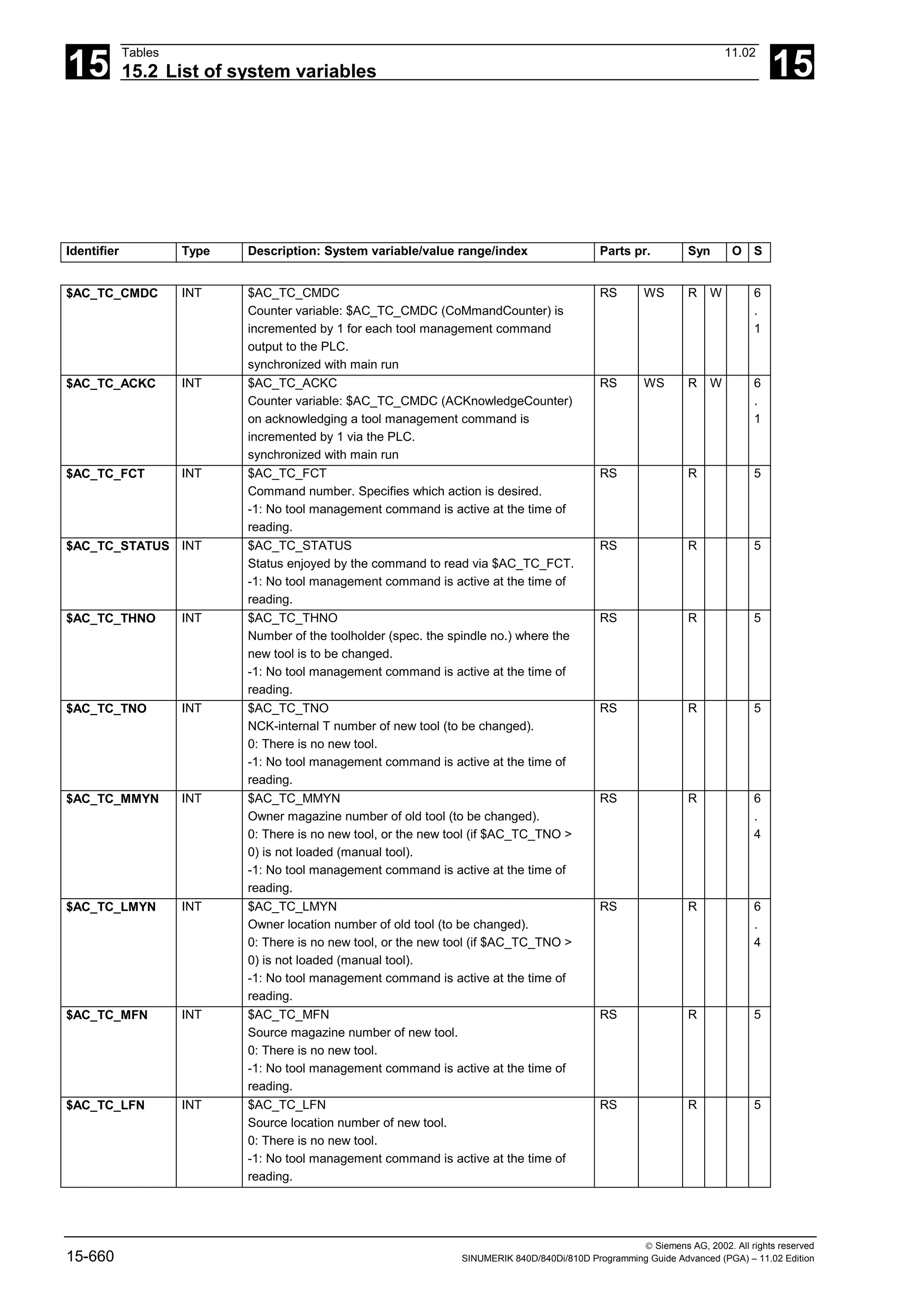
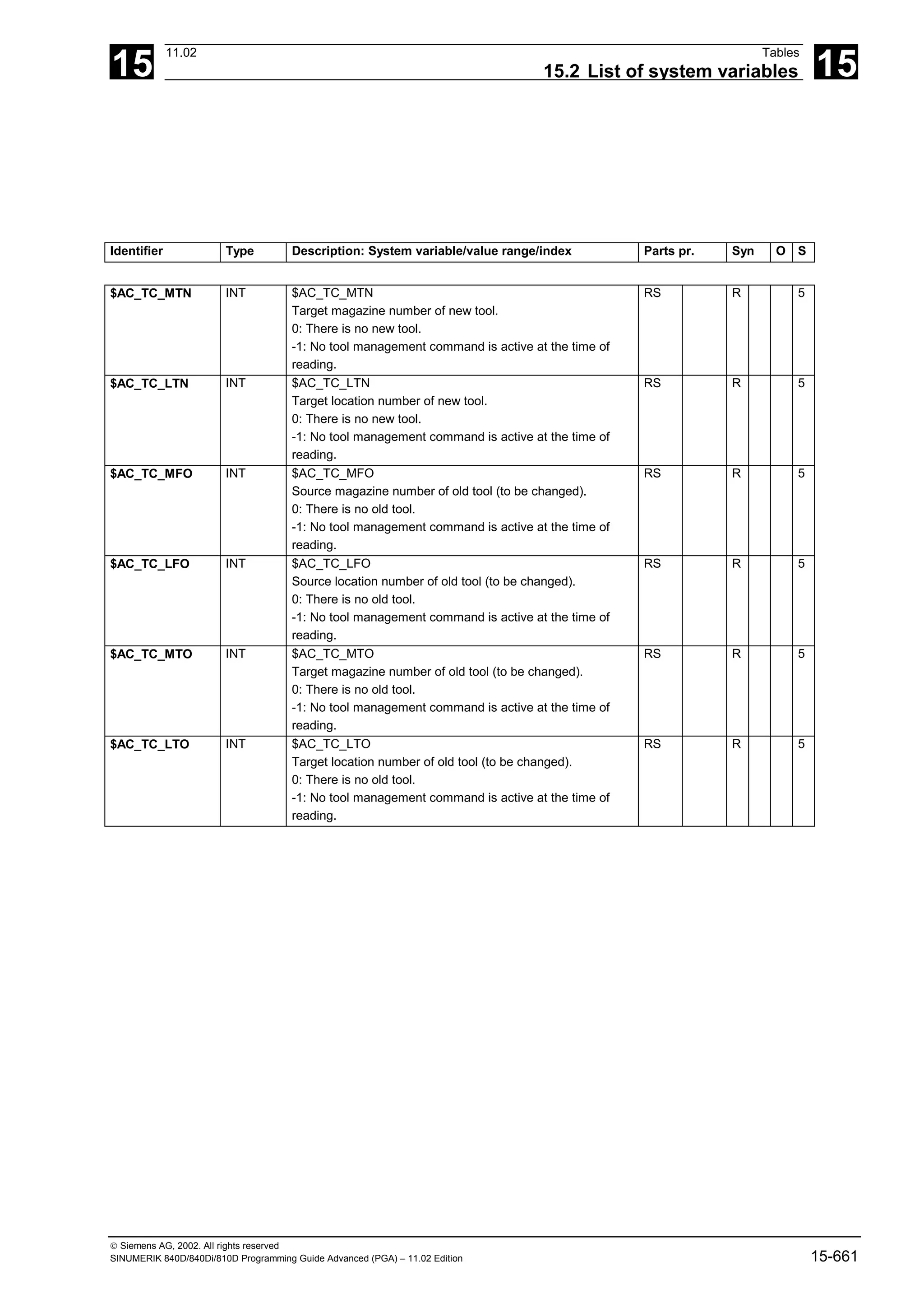
![15
Tables 11.02
15.2 List of system variables 15
Siemens AG, 2002. All rights reserved
15-662 SINUMERIK 840D/840Di/810D Programming Guide Advanced (PGA) – 11.02 Edition
15.2.37 Timers
Identifier Type Description: System variable/value range/index Parts pr. Syn O S
$A_YEAR INT $A_YEAR
System time, year
RS R 3
$A_MONTH INT $A_MONTH
System time, month
RS R 3
$A_DAY INT $A_DAY
System time, day
RS R 3
$A_HOUR INT $A_HOUR
System time, hour
RS R 3
$A_MINUTE INT $A_MINUTE
System time, minute
RS R 3
$A_SECOND INT $A_SECOND
System time, second
RS R 3
$A_MSECOND INT $A_MSECOND
System time, millisecond
RS R 3
$AC_TIME REAL $AC_TIME
Time from the beginning of block in seconds
This variable can only be accessed from synchronized
actions
RS R 2
$AC_TIMEC REAL $AC_TIMEC
Time from the beginning of block in IPO clock cycles
This variable can only be accessed from synchronized
actions
RS R 3
$AC_TIMER REAL $AC_TIMER[n]
Timer - unit in seconds
Time is counted internally in multiples of the interpolation
cycle;
Counting for the time variable is started by assigning the
value
$AC_TIMER[n]=<starting value>
To stop the counter variable, assign a negative value:
$AC_TIMER[n]=-1
The current time can be read while the counter is active or
stopped. Stopping the time variable, by assigning - 1
stops the last current time value which can then be read
The dimension is defined in MD $MC_MM_NUM_AC_TIMER.
RS WS R W + 4](https://image.slidesharecdn.com/fadaladvancedprogrammingmanual-220505063253/75/Fadal-Advanced-Programming-Manual-pdf-662-2048.jpg)
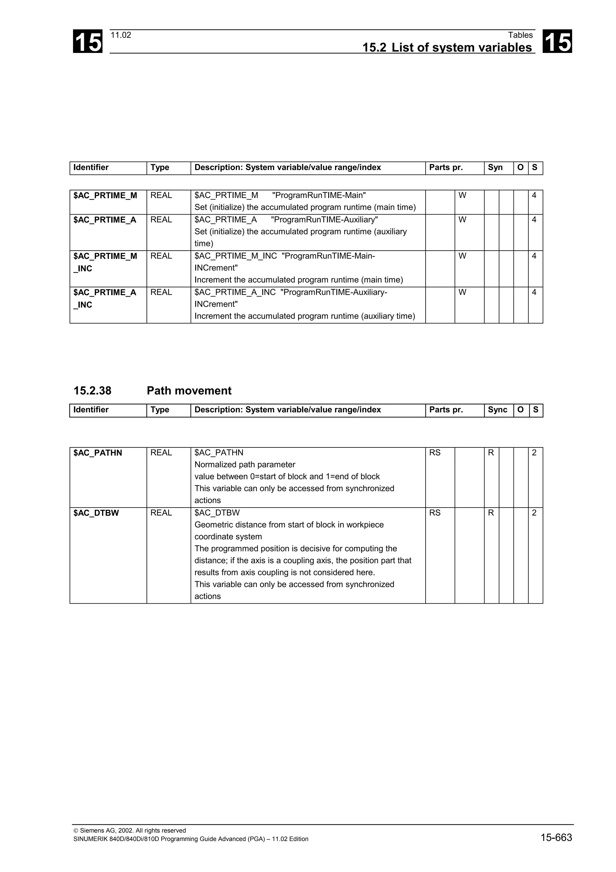
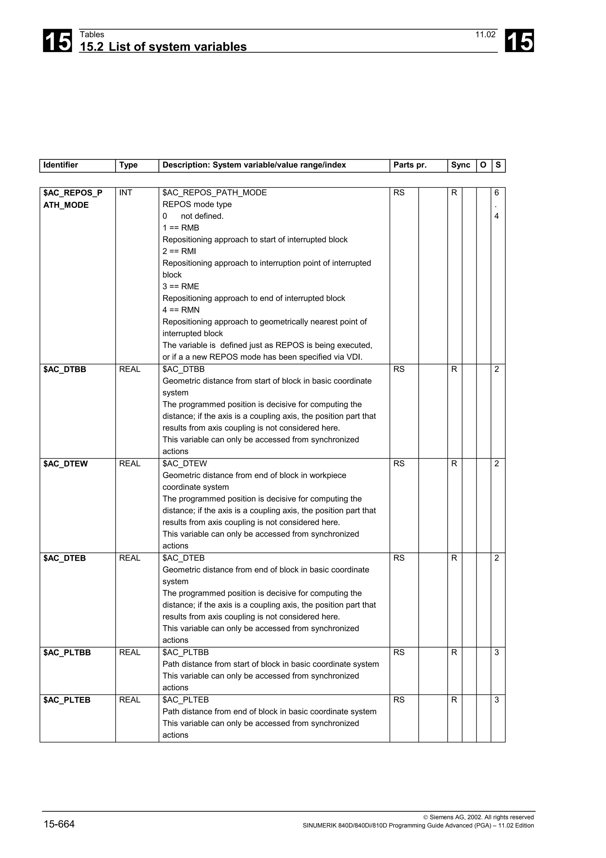
![15
11.02 Tables
15.2 List of system variables 15
Siemens AG, 2002. All rights reserved
SINUMERIK 840D/840Di/810D Programming Guide Advanced (PGA) – 11.02 Edition 15-665
Identifier Type Description: System variable/value range/index Parts pr. Sync O S
$AC_DELT REAL $AC_DELT
Stored distance-to-go path in the workpiece coordinate
system subsequent to deletion of the residual distance
during synchronized motion actions
R 3
$P_APDV BOOL $P_APDV
Returns True if the position values readable with
$P_APR[X] and $P_AEP[X] (approach and depart starting
point and contour point when smoothing) are valid.
R 4
15.2.39 Speeds/accelerations
Identifier Type Description: System variable/value range/index Parts pr. Sync O S
$P_F REAL $P_F
Path feed F last programmed
R 2
$AC_F REAL $AC_F
Programmed path feed F
R 6
.
3
$AC_OVR REAL $AC_OVR:
Path override for synchronized actions
Multiplicative override component, works in addition to
operation OV, programmed OV and transformation OV.
However, the overall factor remains limited to the maximum
value defined by machine data
$MN_OVR_FACTOR_LIMIT_BIN and
$MN_OVR_FACTOR_FEEDRATE[31].
If a value of < 0.0 is entered, 0 is assumed and alarm
14756 reported.
Must be rewritten in every interpolator cycle, otherwise the
value is 100%.
This variable can only be accessed from synchronized
actions
R W 2](https://image.slidesharecdn.com/fadaladvancedprogrammingmanual-220505063253/75/Fadal-Advanced-Programming-Manual-pdf-665-2048.jpg)
![15
Tables 11.02
15.2 List of system variables 15
Siemens AG, 2002. All rights reserved
15-666 SINUMERIK 840D/840Di/810D Programming Guide Advanced (PGA) – 11.02 Edition
Identifier Type Description: System variable/value range/index Parts pr. Sync O S
$AC_VC REAL $AC_VC
Additive path feed compensation for synchronized actions
The compensation value does not work with G0, G33,
G331, G332 and G63.
It must be rewritten in every interpolator cycle, otherwise the
value is 0.
With an override of 0, the compensation value has no
effect, otherwise the override has no impact on the
compensation value.
The compensation value cannot make the total feedrate
negative.
The upper value is limited such that the maximum axis
velocities and accelerations are not exceeded.
The computation with different feedrate components is not
affected by $AC_VC.
The override defined by machine data
$MN_OVR_FACTOR_LIMIT_BIN,
$MN_OVR_FACTOR_FEEDRATE[30],
$MN_OVR_FACTOR_AX_SPEED[30] and
$MN_OVR_FACTOR_SPIND_SPEED
Override values cannot be exceeded. The additive feedrate
override is limited such that the resulting feedrate does not
exceed the maximum override value of the programmed
feedrate.
This variable can only be accessed from synchronized
actions
R W 2
$AC_PATHACC REAL $AC_PATHACC
Specification of an increased path acceleration for override
changes and Stop/Start events.
$AC_PATHACC is only considered when the value is
greater than the prepared acceleration limitation.
The value 0 deselects the function.
Values that lead to machine axis accelerations that are
twice as high as that parameterized in
$MA_MAX_AX_ACCEL[..], are accordingly restricted
internally.
RS WS R W 6
.
3
$AC_PATHJERK REAL $AC_PATHJERK
Specification of an increased path jerk for override changes
and Stop/Start events.
$AC_PATHJERK is only considered when the value is
greater than the prepared jerk limitation.
The value 0 deselects the function.
RS WS R W 6
.
3
$AC_VACTB REAL $AC_VACTB
Path velocity in the base coordinate system
This variable can only be accessed from synchronized
actions
RS R 2
$AC_VACTW REAL $AC_VACTW
Path velocity in workpiece coordinate system
This variable can only be accessed from synchronized
actions
RS R 2](https://image.slidesharecdn.com/fadaladvancedprogrammingmanual-220505063253/75/Fadal-Advanced-Programming-Manual-pdf-666-2048.jpg)
![15
11.02 Tables
15.2 List of system variables 15
Siemens AG, 2002. All rights reserved
SINUMERIK 840D/840Di/810D Programming Guide Advanced (PGA) – 11.02 Edition 15-667
15.2.40 Spindles
Identifier Type Description: System variable/value range/index Parts pr. Sync O S
$P_S REAL $P_S[n]
Last programmed spindle speed
n: Spindle number
0 ... max. spindle number
R 2
$AA_S REAL $AA_S[n]
Spindle actual speed. The sign corresponds to the direction
of rotation.
n: Spindle number
0 ... max. spindle number
RS R 4
$P_CONSTCUT
_S
REAL $P_CONSTCUT_S[n]
Last programmed constant cutting speed.
n: Spindle number
0 ... max. spindle number
R 6
.
1
$AC_CONSTCU
T_S
REAL $AC_CONSTCUT_S[n]
Current constant cutting speed.
n: Spindle number
0 ... max. spindle number
RS R 6
.
1
$P_SEARCH_S REAL $P_SEARCH_S[n]
The last programmed spindle speed or cutting rate picked
up during search mode
n: Spindle number
0 ... max. spindle number
R 6
.
1
$P_SDIR INT $P_SDIR[n]
Last direction of spindle rotation to be programmed.
3: Clockwise spindle rotation,
4: Counterclockwise spindle rotation,
5: Spindle stop
n: Spindle number
0 ... max. spindle number
R 3
$AC_SDIR INT $AC_SDIR[n]
Current direction of spindle rotation
3: Clockwise spindle rotation,
4: Counterclockwise spindle rotation,
5: Spindle stop
n: Spindle number
0 ... max. spindle number
RS R 3
$P_SEARCH_S
DIR
INT $P_SEARCH_SDIR[n]
The last programmed spindle programming picked up
during search mode:
3: M3 Clockwise spindle rotation
4: M4 Counterclockwise spindle rotation
5: M5 Spindle stop
-19: M19, SPOS, SPOSA spindle positioning, position and
approach mode are read from SEARCH variables
70: M70 Switch over to axis mode
-5: No direction of spindle rotation programmed, no output.
n: Spindle number
0 ... max. spindle number
R 6
.
1](https://image.slidesharecdn.com/fadaladvancedprogrammingmanual-220505063253/75/Fadal-Advanced-Programming-Manual-pdf-667-2048.jpg)
![15
Tables 11.02
15.2 List of system variables 15
Siemens AG, 2002. All rights reserved
15-668 SINUMERIK 840D/840Di/810D Programming Guide Advanced (PGA) – 11.02 Edition
Identifier Type Description: System variable/value range/index Parts pr. Sync O S
$P_SMODE INT $P_SMODE[n]
Last programmed spindle mode:
0: No spindle in the channel or spindle is active in another
channel or
is being used by the PLC (FC18) or by synchronized
actions.
1: Speed control mode
2: Positioning mode
3: synchronized mode
4: Axis mode
n: Spindle number
0 ... max. spindle number
R 3
$AC_SMODE INT $AC_SMODE[n]
Spindle mode currently active
0: No spindle in the channel
1: Speed control mode
2: Positioning mode
3: synchronized mode
4: Axis mode
n: Spindle number
0 ... max. spindle number
RS R 3
$P_SGEAR INT $P_SGEAR[n]
Spindle gear stage last programmed or requested during
M40 by S programming
1: 1st gear stage requested
....
5: 5th gear stage requested
n: Spindle number
0 ... max. spindle number
R 6
.
1
$AC_SGEAR INT $AC_SGEAR[n]
Active spindle gear stage
1: 1st gear stage is active
....
5: 5th gear stage is active
n: Spindle number
0 ... max. spindle number
RS R 6
.
1
$P_SAUTOGEAR INT $P_SAUTOGEAR[n]
Automatic gear stage change (M40) is programmed.
0: Gear stages are requested by M41..M45
1: The gear stage is calculated and requested (M40
Automatic gear stage change is active) to fit the
programmed speed (S)
n: Spindle number
0 ... max. spindle number
R 6
.
1](https://image.slidesharecdn.com/fadaladvancedprogrammingmanual-220505063253/75/Fadal-Advanced-Programming-Manual-pdf-668-2048.jpg)
![15
11.02 Tables
15.2 List of system variables 15
Siemens AG, 2002. All rights reserved
SINUMERIK 840D/840Di/810D Programming Guide Advanced (PGA) – 11.02 Edition 15-669
Identifier Type Description: System variable/value range/index Parts pr. Sync O S
$P_SEARCH_S
GEAR
INT $P_SEARCH_SGEAR[n]
The last programmed gear stages M function picked up
during search mode.
40: M40 Automatic gear stage change
41: M41 1st gear stage requested
...
45: M45 5th gear stage requested
n: Spindle number
0 ... max. spindle number
R 6
.
1
$P_SEARCH_S
POS
REAL $P_SEARCH_SPOS[n]
The last spindle position or travel path programmed by M19,
SPOS or SPOSA
picked up during search mode.
Position: 0...359.999, when the value in MD 30330
MODULO_RANGE is 360.0 degrees
Path: -100000000 ... 100000000 degrees. The sign
indicates the traversing direction.
n: Spindle number
0 ... max. spindle number
R W 6
.
1
$P_SEARCH_S
POSMODE
INT $P_SEARCH_SPOSMODE[n]
The last position approach mode programmed by M19,
SPOS or SPOSA picked up during search mode.
0: DC
1: AC
2: IC
3: DC
4: ACP
5: ACN
n: Spindle number
0 ... max. spindle number
R W 6
.
1
$P_NUM_SPIND
LES
INT $P_NUM_SPINDLES
Calculates the maximum number of spindles in the channel
0: No spindle in the channel.
1..n: Number of spindles in the channel
R 6
.
1
$P_MSNUM INT $P_MSNUM
Returns the number of the master spindle.
0: No spindle in the channel
1..n: Number of the master spindle
R 6
.
1
$AC_MSNUM INT $AC_MSNUM
Returns the number of the current master spindle.
0: No spindle exists
1..n: Number of the master spindle
RS R 3
$P_MTHNUM INT $P_MTHNUM - only useful with active magazine
management
Returns the number of the master tool carrier:
0: No master tool carrier
1..n: Number of master tool carrier
R 6
.
1](https://image.slidesharecdn.com/fadaladvancedprogrammingmanual-220505063253/75/Fadal-Advanced-Programming-Manual-pdf-669-2048.jpg)
![15
Tables 11.02
15.2 List of system variables 15
Siemens AG, 2002. All rights reserved
15-670 SINUMERIK 840D/840Di/810D Programming Guide Advanced (PGA) – 11.02 Edition
Identifier Type Description: System variable/value range/index Parts pr. Sync O S
$AC_MTHNUM INT $AC_MTHNUM - only useful with active magazine
management
Returns the number of the current master tool carrier:
0: No master tool carrier
1..n: Number of master tool carrier
RS R 6
.
1
$P_GWPS BOOL $P_GWPS[n]
Constant grinding wheel surface speed on if TRUE
n: Spindle number
R 2
15.2.41 Polynomial values for synchronized actions
$AC_FCT1LL REAL $AC_FCT1LL
Lower limit value for evaluation function FCTDEF 1
RS WS R W + 2
$AC_FCT2LL REAL $AC_FCT2LL
Lower limit value for evaluation function FCTDEF 2
RS WS R W + 2
$AC_FCT3LL REAL $AC_FCT3LL
Lower limit value for evaluation function FCTDEF 3
RS WS R W + 2
$AC_FCT1UL REAL $AC_FCT1UL
Upper limit value for evaluation function FCTDEF 1
RS WS R W + 2
$AC_FCT2UL REAL $AC_FCT2UL
Upper limit value for evaluation function FCTDEF 2
RS WS R W + 2
$AC_FCT3UL REAL $AC_FCT3UL
Upper limit value for evaluation function FCTDEF 3
RS WS R W + 2
$AC_FCT1C REAL $AC_FCT1C[n]
Polynomial coefficient a0–a3 for evaluation function
FCTDEF 1
n: Degree of coefficient 0–3
RS WS R W + 2
$AC_FCT2C REAL $AC_FCT2C[n]
Polynomial coefficient a0–a3 for evaluation function
FCTDEF 2
n: Degree of coefficient 0–3
RS WS R W + 2
$AC_FCT3C REAL $AC_FCT3C[n]
Polynomial coefficient a0–a3 for evaluation function
FCTDEF 3
n: Degree of coefficient 0–3
RS WS R W + 2
$AC_FCTLL REAL $AC_FCTLL[n]
Lower limit of polynomial for synchronized actions
(SYNFCT)
n: Number of polynomial, limited by machine data
RS WS R W + 4
$AC_FCTUL REAL $AC_FCTUL[n]
Upper limit of polynomial for synchronized actions
(SYNFCT)
n: Number of polynomial, limited by machine data
RS WS R W + 4](https://image.slidesharecdn.com/fadaladvancedprogrammingmanual-220505063253/75/Fadal-Advanced-Programming-Manual-pdf-670-2048.jpg)
![15
11.02 Tables
15.2 List of system variables 15
Siemens AG, 2002. All rights reserved
SINUMERIK 840D/840Di/810D Programming Guide Advanced (PGA) – 11.02 Edition 15-671
Identifier Type Description: System variable/value range/index Parts pr. Sync O S
$AC_FCT0 REAL $AC_FCT0[n]
a0 coefficient of polynomial for synchronized actions
(SYNFCT)
n: Number of polynomial, limited by machine data
RS WS R W + 4
$AC_FCT1 REAL $AC_FCT1[n]
a1 coefficient of polynomial for synchronized actions
(SYNFCT)
n: Number of polynomial, limited by machine data
RS WS R W + 4
$AC_FCT2 REAL $AC_FCT2[n]
a2 coefficient of polynomial for synchronized actions
(SYNFCT)
n: Number of polynomial, limited by machine data
RS WS R W + 4
$AC_FCT3 REAL $AC_FCT3[n]
a3 coefficient of polynomial for synchronized actions
(SYNFCT)
n: Number of polynomial, limited by machine data
RS WS R W + 4](https://image.slidesharecdn.com/fadaladvancedprogrammingmanual-220505063253/75/Fadal-Advanced-Programming-Manual-pdf-671-2048.jpg)
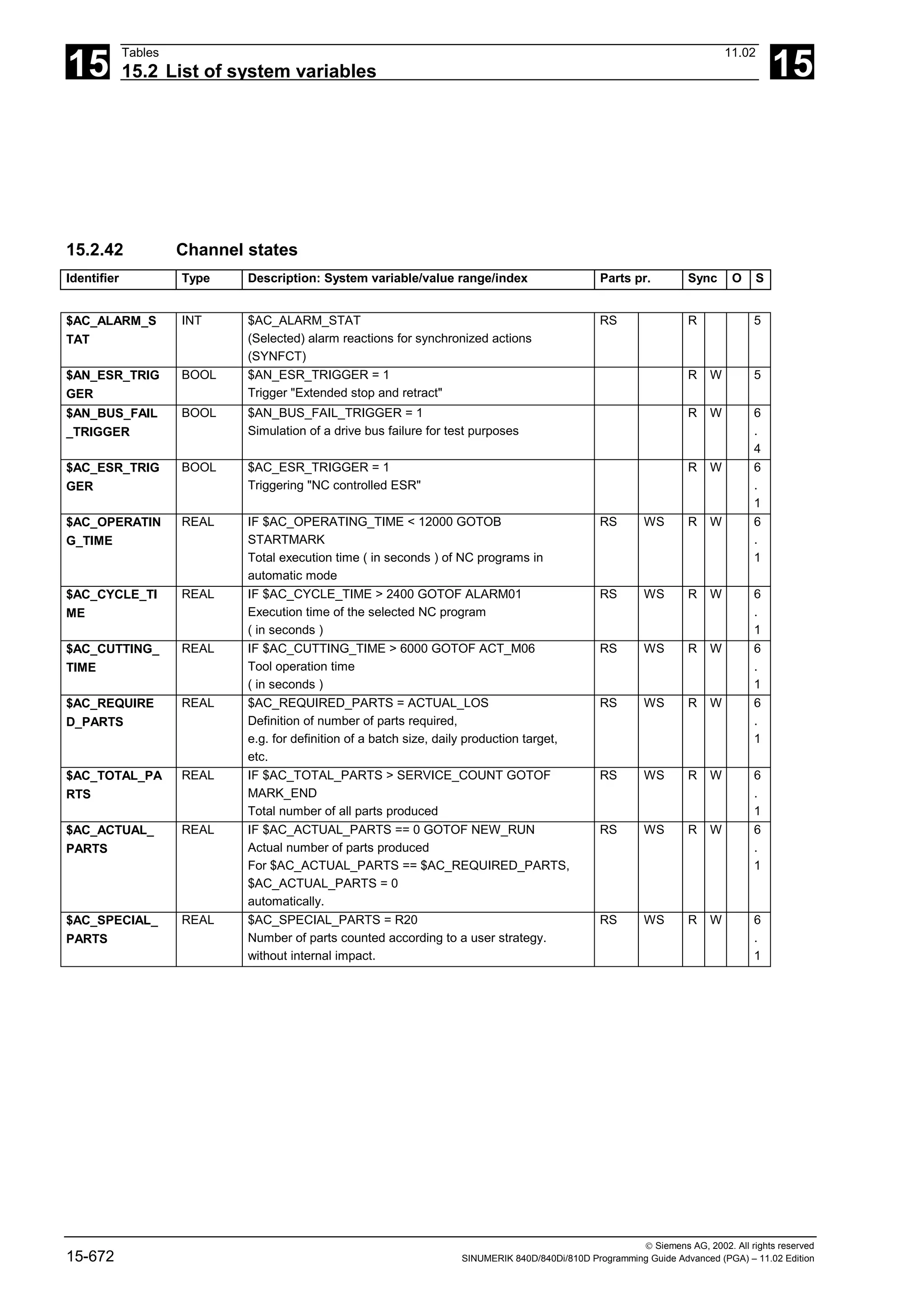
![15
11.02 Tables
15.2 List of system variables 15
Siemens AG, 2002. All rights reserved
SINUMERIK 840D/840Di/810D Programming Guide Advanced (PGA) – 11.02 Edition 15-673
Identifier Type Description: System variable/value range/index Parts pr. Sync O S
$AC_G0MODE INT $AC_G0MODE
0: G0 not active
1: G0 and linear interpolation active
2: G0 and nonlinear interpolation active
The response of the path axes at G0 is dependent on
machine data $MC_G0_LINEAR_MODE (Siemens mode)
or $MC_EXTERN_G0_LINEAR_MODE (ISO mode):
with linearer interpolation, the path axes traverse together,
with non-linear interpolation, the path axes traverse as
positioning axes.
R 6
.
1
15.2.43 Measurement
Identifier Type Description: System variable/value range/index Parts pr. Sync O S
$AC_MEAS_SE
MA
INT $AC_MEAS_SEMA = 1
Assigning the measuring interface.
R W 6
.
1
$AC_MEAS_LA
TCH
INT $AC_MEAS_LATCH[0] = 1
Writing the actual axis values to the 1st measuring point.
0: 1st measuring point,
.. ,
3: 4th measuring point
R WS R W 6
.
1
$AC_MEAS_P1_
COORD
INT $AC_MEAS_P1_COORD =
0: WCS
1: BCS
2: MCS
Coordinate system of the 1st measuring point.
R W 6
.
4
$AC_MEAS_P2_
COORD
INT $AC_MEAS_P2_COORD =
0: WCS
1: BCS
2: MCS
Coordinate system of the 2nd measuring point.
R W 6
.
4
$AC_MEAS_P3_
COORD
INT $AC_MEAS_P3_COORD =
0: WCS
1: BCS
2: MCS
Coordinate system of the 3rd measuring point.
R W 6
.
4
$AC_MEAS_P4_
COORD
INT $AC_MEAS_P4_COORD =
0: WCS
1: BCS
2: MCS
Coordinate system of the 4th measuring point.
R W 6
.
4
$AC_MEAS_SE
T_COORD
INT $AC_MEAS_SET_COORD =
0: WCS
1: BCS
2: MCS
Coordinate system of the setpoint.
R W 6
.
4](https://image.slidesharecdn.com/fadaladvancedprogrammingmanual-220505063253/75/Fadal-Advanced-Programming-Manual-pdf-673-2048.jpg)
![15
Tables 11.02
15.2 List of system variables 15
Siemens AG, 2002. All rights reserved
15-674 SINUMERIK 840D/840Di/810D Programming Guide Advanced (PGA) – 11.02 Edition
Identifier Type Description: System variable/value range/index Parts pr. Sync O S
$AC_MEAS_WP
_SETANGLE
REAL $AC_MEAS_WP_SETANGLE = 0.0
Setpoint angle of the part position for part gauging.
R W 6
.
1
$AC_MEAS_CO
RNER_SETANG
LE
REAL $AC_MEAS_CORNER_SETANGLE = 90.0
Setpoint cutting angle of the corner for part gauging.
R W 6
.
1
$AC_MEAS_DIR
_APPROACH
INT $AC_MEAS_DIR_APPROACH =
0: +x
1: -x
2: +y
3: -y
4: +z
5: -z
Direction of approach to the part.
R W 6
.
1
$AC_MEAS_AC
T_PLANE
INT $AC_MEAS_ACT_PLANE =
0: G17
1: G18
2: G19
Setting the plane for calculation and measuring.
R W 6
.
1
$AC_MEAS_FIN
E_TRANS
INT $AC_MEAS_FINE_TRANS =
0: Offset in Trans
1: Offset in Fine Trans
Setting the fine offset for calculation and measuring.
R W 6
.
3
$AC_MEAS_FR
AME_SELECT
INT $AC_MEAS_FRAME_SELECT =
0: $P_SETFRAME
10..25: $P_CHBFRAME[0..15]
50..65: $P_NCBFRAME[0..15]
100..199: $P_IFRAME
1010..1025: $P_CHBFRAME[0..15], with active G500
1050..1065: $P_NCBFRAME[0..15], with active G500
2000: $P_SETFR
2010..2025: $P_CHBFR[0..15]
2050..2065: $P_NCBFR[0..15]
2100..2199: $P_UIFR[0..99]
3010..3025: $P_CHBFR[0..15], with active G500
3050..3065: $P_NCBFR[0..15], with active G500
Selecting the frames for part gauging.
R W 6
.
1
$AC_MEAS_CH
SFR
INT $AC_MEAS_CHSFR = 'B1001'
System frame bit mask in accordance with
$MC_MM_SYSTEM_FRAME_MASK
R W 6
.
4
$AC_MEAS_NC
BFR
INT $AC_MEAS_NCBFR = 'B1'
Global basic frame mask to set up the new frame.
R W 6
.
4
$AC_MEAS_CH
BFR
INT $AC_MEAS_CHBFR = 'B1'
Channel basic frame mask to set up the new frame.
R W 6
.
4
$AC_MEAS_UIFR INT $AC_MEAS_UIFR = 1
Adjustable data management frame to set up the new
frame.
R W 6
.
4](https://image.slidesharecdn.com/fadaladvancedprogrammingmanual-220505063253/75/Fadal-Advanced-Programming-Manual-pdf-674-2048.jpg)
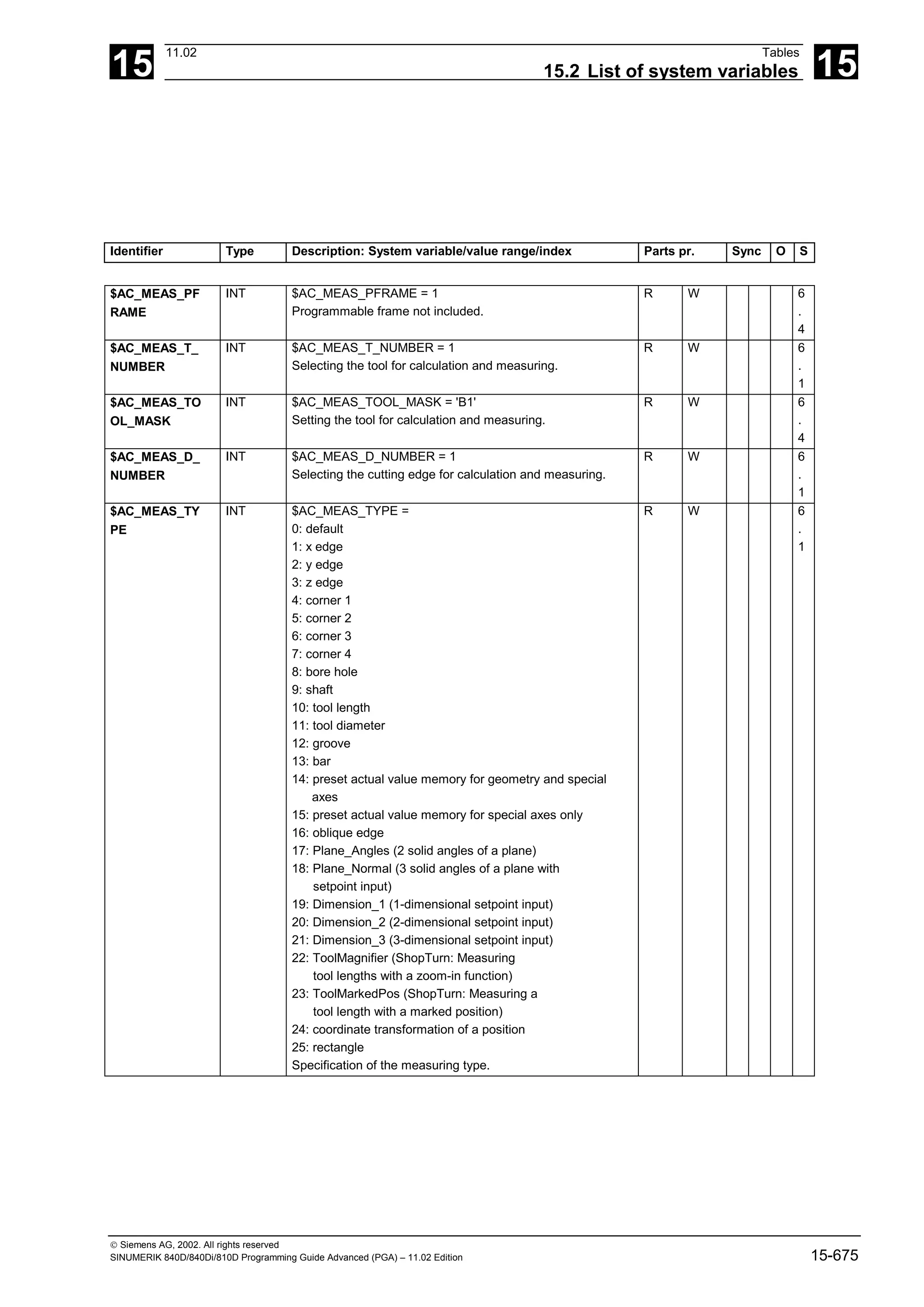
![15
Tables 11.02
15.2 List of system variables 15
Siemens AG, 2002. All rights reserved
15-676 SINUMERIK 840D/840Di/810D Programming Guide Advanced (PGA) – 11.02 Edition
Identifier Type Description: System variable/value range/index Parts pr. Sync O S
$AC_MEAS_VA
LID
INT $AC_MEAS_VALID = 0
Validity bits of the measuring variables. The value should
be set to 0 prior to all measuring processes. The individual
bits are set implicitly when writing to the corresponding
variables.
Bit 0: $AA_MEAS_POINT1[axis]
Bit 1: $AA_MEAS_POINT2[axis]
Bit 2: $AA_MEAS_POINT3[axis]
Bit 3: $AA_MEAS_POINT4[axis]
Bit 4: $AA_MEAS_SETPOINT[axis]
Bit 5: $AC_MEAS_WP_SETANGLE
Bit 6: $AC_MEAS_CORNER_SETANGLE
Bit 7: $AC_MEAS_T_NUMBER
Bit 8: $AC_MEAS_D_NUMBER
Bit 9: $AC_MEAS_DIR_APPROACH
Bit 10 :$AC_MEAS_ACT_PLANE
Bit 11: $AC_MEAS_FRAME_SELECT
Bit 12: $AC_MEAS_TYPE
Bit 13: $AC_MEAS_FINE_TRANS
Bit 14: $AA_MEAS_SETANGLE[axis]
Bit 15: $AC_MEAS_SCALEUNIT
Bit 16: $AC_MEAS_TOOL_MASK
Bit 17: $AC_MEAS_P1_COORD
Bit 18: $AC_MEAS_P2_COORD
Bit 19: $AC_MEAS_P3_COORD
Bit 20: $AC_MEAS_P4_COORD
Bit 21: $AC_MEAS_SET_COORD
Bit 22: $AC_MEAS_CHSFR
Bit 23: $AC_MEAS_NCBFR
Bit 24: $AC_MEAS_CHBFR
Bit 25: $AC_MEAS_UIFR
Bit 26: $AC_MEAS_PFRAME
R W 6
.
1
$AC_MEAS_FR
AME
FRAME $AC_MEAS_FRAME
Result frame for part gauging.
R W 6
.
1
$AC_MEAS_WP
_ANGLE
REAL $AC_MEAS_WP_ANGLE
Calculated part position angle for part gauging.
R 6
.
1
$AC_MEAS_CO
RNER_ANGLE
REAL $AC_MEAS_CORNER_ANGLE
Calculated cutting angle of the corner for part gauging.
R 6
.
1
$AC_MEAS_DIA
METER
REAL $AC_MEAS_DIAMETER
Calculated diameter for part and tool gauging.
R 6
.
1
$AC_MEAS_TO
OL_LENGTH
REAL $AC_MEAS_TOOL_LENGTH
Calculated tool length for tool gauging.
R 6
.
1](https://image.slidesharecdn.com/fadaladvancedprogrammingmanual-220505063253/75/Fadal-Advanced-Programming-Manual-pdf-676-2048.jpg)
![15
11.02 Tables
15.2 List of system variables 15
Siemens AG, 2002. All rights reserved
SINUMERIK 840D/840Di/810D Programming Guide Advanced (PGA) – 11.02 Edition 15-677
Identifier Type Description: System variable/value range/index Parts pr. Sync O S
$AC_MEAS_RE
SULTS
REAL R0 = $AC_MEAS_RESULTS[0]
Measured results
R 6
.
3
$AC_MEAS_SC
ALEUNIT
INT Unit of measurement in accordance with the configuration
$AC_MEAS_SCALEUNIT = 0
Unit of measurement relative to the active G code
G70/G700/G71/G710
R W 6
.
4
$P_CHANNO INT Query the current channel number. R 6
.
4
$AC_SERUPRO INT $AC_SERUPRO
Query whether search run type SERUPRO is active.
(SERUPRO: "Search run via program testing")
Possible to use in SYNACTs and in the parts program
$AC_SERUPRO == 0 SERUPRO search run type not
active
$AC_SERUPRO == 1 SERUPRO search run type is
active
R 6
.
4
15.2.44 Positions
$P_EP REAL $P_EP[X]
The system variable $P_EP always returns the current
WCS setpoint position in the interpreter. The numerical
value is not inevitably the same as the programmed value in
the parts program. In the following situations there are
differences
- during incremental programming
- when changing the WCS by frame or tool selection
If an ASUB starts after a block search with calculation, this
event will synchronize positions in the interpreter. $P_EP
then returns in ASUB the position at which the axes actually
are. The search run position that is picked up can be
queried via system variable $AC_RETPOINT.
Axes: channel axis
R 2](https://image.slidesharecdn.com/fadaladvancedprogrammingmanual-220505063253/75/Fadal-Advanced-Programming-Manual-pdf-677-2048.jpg)
![15
Tables 11.02
15.2 List of system variables 15
Siemens AG, 2002. All rights reserved
15-678 SINUMERIK 840D/840Di/810D Programming Guide Advanced (PGA) – 11.02 Edition
Identifier Type Description: System variable/value range/index Parts pr. Sync O S
$P_EPM REAL $P_EPM[X]
Current MCS position in the interpreter (also see $P_EP).
Axes: channel axis
R 6
.
1
$P_APR REAL $P_APR[X]
Position of axis in the workpiece coordinate system at the
start of the approach motion for soft approach to the
contour. Axes: channel axis
R 4
$P_AEP REAL $P_AEP[X]
Approach point: first contour point in the workpiece
coordinate system for soft approach to contour. Axes:
channel axis
R 4
$P_POLF REAL $P_POLF[X]
X: Axis
returns the programmed return position of the axis
Axes: geometry axis, channel axis, machine axis
R 6
.
4
$P_POLF_VALID INT $P_POLF_VALID[X]
X: Axis
0: no axis return programmed
1: return programmed in abs. position
2: return programmed as distance
Axes: geometry axis, channel axis, machine axis
R 6
.
4
$AA_IW REAL $AA_IW[X]
Actual value in workpiece coordinate system (WCS)
Axes: channel axis
RS R 2
$AA_REPOS_D
ELAY
BOOL $AA_REPOS_DELAY[X]
TRUE: For this axis REPOS suppression is just active.
FALSE: otherwise
Axes: channel axis
RS R + 6
.
4
$AA_IEN REAL $AA_IEN[X]
Actual value in the settable origin system (SOS).
Axes: channel axis
RS R 5
$AA_IBN REAL $AA_IBN[X]
Actual value in the basic origin system (BOS).
Axes: channel axis
RS R 5
$AA_IB REAL $AA_IB[X]
Actual value in basic coordinate system (BCS)
Axes: channel axis
RS R 2
$AA_IM REAL $AA_IM[X]
Actual value in machine coordinate system (MCS).
Axes: geometry axis, channel axis, machine axis
RS R 2](https://image.slidesharecdn.com/fadaladvancedprogrammingmanual-220505063253/75/Fadal-Advanced-Programming-Manual-pdf-678-2048.jpg)
![15
11.02 Tables
15.2 List of system variables 15
Siemens AG, 2002. All rights reserved
SINUMERIK 840D/840Di/810D Programming Guide Advanced (PGA) – 11.02 Edition 15-679
15.2.45 Indexing axes
Identifier Type Description: System variable/value range/index Parts pr. Sync O S
$AA_ACT_INDE
X_AX_POS_NO
INT $AA_ACT_INDEX_AX_POS_NO[X]
0: No indexing axis, therefore no indexing position available.
> 0: Number of indexing position last reached or crossed
Axes: geometry axis, channel axis, machine axis
RS R 5
$AA_PROG_INDE
X_AX_POS_NO
INT $AA_PROG_INDEX_AX_POS_NO[X]
0: No indexing axis, thus no indexing position
available or indexing axis currently not approaching
an indexing position
> 0: Number of programmed indexing position
Axes: geometry axis, channel axis, machine axis
RS R 5
15.2.46 Encoder values
$AA_ENC_ACTI
VE
BOOL $AA_ENC_ACTIVE[X]
Active measuring system is operating below encoder limit
frequency
Axes: geometry axis, channel axis, machine axis
RS R 4
$AA_ENC1_ACT
IVE
BOOL $AA_ENC1_ACTIVE[X]
Encoder 1 is operating below encoder limit frequency
Axes: geometry axis, channel axis, machine axis
RS R 4
$AA_ENC2_ACT
IVE
BOOL $AA_ENC2_ACTIVE[X]
Encoder 2 is operating below encoder limit frequency
Axes: geometry axis, channel axis, machine axis
RS R 4
$VA_IM REAL $VA_IM[X]
Encoder actual value in machine coordinate system
(measured on active measuring system), actual value
compensations are corrected (leadscrew error
compensation, backlash compensation, quadrant error
compensation)
With active spindle/axis disable, the default return is the
current setpoint. If the actual value is then returned, BIT3
must be set in $MA_MISC_FUNCTION_MASK.
RS R 4](https://image.slidesharecdn.com/fadaladvancedprogrammingmanual-220505063253/75/Fadal-Advanced-Programming-Manual-pdf-679-2048.jpg)
![15
Tables 11.02
15.2 List of system variables 15
Siemens AG, 2002. All rights reserved
15-680 SINUMERIK 840D/840Di/810D Programming Guide Advanced (PGA) – 11.02 Edition
Identifier Type Description: System variable/value range/index Parts pr. Sync O S
$VA_IM1 REAL $VA_IM1[X]
Actual value in the machine coordinate system (measured
Encoder 1), compensations are corrected
With active spindle/axis disable the default return is the
current setpoint. If the actual value is then returned, BIT3
must be set in $MA_MISC_FUNCTION_MASK.
RS R 4
$VA_IM2 REAL $VA_IM2[X]
Actual value in the machine coordinate system (measured
Encoder 2), compensations are corrected
With active spindle/axis disable the default return is the
current setpoint. If the actual value is then returned, BIT3
must be set in $MA_MISC_FUNCTION_MASK.
RS R 4
$AA_MW REAL $AA_MW[X]
Measured value in workpiece coordinate system
Axes: channel axis
R WS R W 2
$AA_MM REAL $AA_MM[X]
Measured value in machine coordinate system
R WS R W 2
$AA_MW1 REAL $AA_MW1[X]
Measurement result of axial measurement
Trigger event 1 in WCS
Axes: channel axis
R WS R W 4
$AA_MW2 REAL $AA_MW2[X]
Measurement result of axial measurement
Trigger event 2 in WCS
Axes: channel axis
R WS R W 4
$AA_MW3 REAL $AA_MW3[X]
Measurement result of axial measurement
Trigger event 3 in WCS
Axes: channel axis
R WS R W 4
$AA_MW4 REAL $AA_MW4[X]
Measurement result of axial measurement
Trigger event 4 in WCS
Axes: channel axis
R WS R W 4
15.2.47 Axial measurement
Identifier Type Description: System variable/value range/index Parts pr. Sync O S
$AA_MM1 REAL $AA_MM1[X]
Measurement result of axial measurement
Trigger event 1 in MCS
R WS R W 4
$AA_MM2 REAL $AA_MM2[X]
Measurement result of axial measurement
Trigger event 2 in MCS
R WS R W 4
$AA_MM3 REAL $AA_MM3[X]
Measurement result of axial measurement
Trigger event 3 in MCS
R WS R W 4](https://image.slidesharecdn.com/fadaladvancedprogrammingmanual-220505063253/75/Fadal-Advanced-Programming-Manual-pdf-680-2048.jpg)
![15
11.02 Tables
15.2 List of system variables 15
Siemens AG, 2002. All rights reserved
SINUMERIK 840D/840Di/810D Programming Guide Advanced (PGA) – 11.02 Edition 15-681
Identifier Type Description: System variable/value range/index Parts pr. Sync O S
$AA_MM4 REAL $AA_MM4[X]
Measurement result of axial measurement
Trigger event 4 in MCS
R WS R W 4
$AA_MEAACT BOOL $AA_MEAACT[X]
Value is TRUE if axial measurement is active for X
Axes: geometry axis, channel axis, machine axis
R 4
15.2.48 Offsets
Identifier Type Description: System variable/value range/index Parts pr. Sync O S
$AC_DRF REAL $AC_DRF[X]
DRF offset
Axes: channel axis
RS R 2
$AC_PRESET REAL $AC_PRESET[X]
Last given PRESET value
Axes: channel axis
RS R 2
$AA_ETRANS REAL $AA_ETRANS[X]
External zero offset
Axes: channel axis
R W 2
$AA_MEAS_P1_
VALID
INT $AA_MEAS_P1_VALID[X] = 1
Writing the actual axis value to the 1st measuring point.
Axes: geometry axis, channel axis, machine axis
R WS R W 6
.
1
$AA_MEAS_P2_
VALID
INT $AA_MEAS_P2_VALID[X] = 1
Writing the actual axis value to the 2nd measuring point.
Axes: geometry axis, channel axis, machine axis
R WS R W 6
.
1
$AA_MEAS_P3_
VALID
INT $AA_MEAS_P3_VALID[X] = 1
Writing the actual axis value to the 3rd measuring point.
Axes: geometry axis, channel axis, machine axis
R WS R W 6
.
1
$AA_MEAS_P4_
VALID
INT $AA_MEAS_P4_VALID[X] = 1
Writing the actual axis value to the 4th measuring point.
Axes: geometry axis, channel axis, machine axis
R WS R W 6
.
1
$AA_MEAS_POI
NT1
REAL $AA_MEAS_POINT1[x] = $AA_IW[x]
$AA_MEAS_POINT1[y] = $AA_IW[y]
$AA_MEAS_POINT1[z] = $AA_IW[z]
First measuring point for part and tool gauging.
Axes: geometry axis, channel axis, machine axis
R W 6
.
1
$AA_MEAS_POI
NT2
REAL $AA_MEAS_POINT2[x] = $AA_IW[x]
$AA_MEAS_POINT2[y] = $AA_IW[y]
$AA_MEAS_POINT2[z] = $AA_IW[z]
Second measuring point for part and tool gauging.
Axes: geometry axis, channel axis, machine axis
R W 6
.
1](https://image.slidesharecdn.com/fadaladvancedprogrammingmanual-220505063253/75/Fadal-Advanced-Programming-Manual-pdf-681-2048.jpg)
![15
Tables 11.02
15.2 List of system variables 15
Siemens AG, 2002. All rights reserved
15-682 SINUMERIK 840D/840Di/810D Programming Guide Advanced (PGA) – 11.02 Edition
Identifier Type Description: System variable/value range/index Parts pr. Sync O S
$AA_MEAS_POI
NT3
REAL $AA_MEAS_POINT3[x] = $AA_IW[x]
$AA_MEAS_POINT3[y] = $AA_IW[y]
$AA_MEAS_POINT3[z] = $AA_IW[z]
Third measuring point for part and tool gauging.
Axes: geometry axis, channel axis, machine axis
R W 6
.
1
$AA_MEAS_POI
NT4
REAL $AA_MEAS_POINT4[x] = $AA_IW[x]
$AA_MEAS_POINT4[y] = $AA_IW[y]
$AA_MEAS_POINT4[z] = $AA_IW[z]
Fourth measuring point for part and tool gauging.
Axes: geometry axis, channel axis, machine axis
R W 6
.
1
$AA_MEAS_SP
_VALID
INT $AA_MEAS_SP_VALID[X] = 0
Invalidating the x-axis setpoint for part and tool gauging.
Axes: geometry axis, channel axis, machine axis
R W 6
.
1
$AA_MEAS_SE
TPOINT
REAL $AA_MEAS_SETPOINT[X] = 0.0
$AA_MEAS_SETPOINT[y] = 0.0
$AA_MEAS_SETPOINT[z] = 0.0
Setpoint position for part and tool gauging.
Axes: geometry axis, channel axis, machine axis
R W 6
.
1
$AA_MEAS_SE
TANGLE
REAL $AA_MEAS_SETANGLE[x] = 0.0
$AA_MEAS_SETANGLE[y] = 0.0
$AA_MEAS_SETANGLE[z] = 0.0
Setpoint angle for part and tool gauging.
Axes: geometry axis, channel axis, machine axis
R W 6
.
4
$AA_OFF REAL $AA_OFF[X]
Overlaid motion for programmed axis
Axes: geometry axis, channel axis, machine axis
RS W R W 3
$AA_OFF_LIMIT INT $AA_OFF_LIMIT[axis]
Limit value for axial offset $AA_OFF[axis]
0: Limit value not reached
1: Limit value reached in positive axis direction
-1: Limit value reached in negative axis direction
Axes: geometry axis, channel axis, machine axis
RS R 4
$AA_OFF_VAL REAL $AA_OFF_VAL[axis]
Integrated value of the overlaid movement for one axis.
An overlaid movement can be undone by using the negative
value of these variables.
For example $AA_OFF[axis] = -$AA_OFF_VAL[axis]
Axes: geometry axis, channel axis, machine axis
RS R 6
.
1](https://image.slidesharecdn.com/fadaladvancedprogrammingmanual-220505063253/75/Fadal-Advanced-Programming-Manual-pdf-682-2048.jpg)
![15
11.02 Tables
15.2 List of system variables 15
Siemens AG, 2002. All rights reserved
SINUMERIK 840D/840Di/810D Programming Guide Advanced (PGA) – 11.02 Edition 15-683
Identifier Type Description: System variable/value range/index Parts pr. Sync O S
$AC_RETPOINT REAL $AC_RETPOINT[X]
$AC_RETPOINT[] returns the WCS position of an axis at
which an ASUB was started. Then repositioning to this
position can take place in the ASUB.
If an ASUB is started up directly after a block search with
calculation, $AC_RETPOINT returns the search run
position that has been picked up.
Axes: channel axis
RS R 2
$AA_TOFF REAL $AA_TOFF[geometry axis]
Overlaid value in the tool coordinate system.
Axes: geometry axis
RS W R W 6
.
4
$AA_TOFF_VAL REAL $AA_TOFF_VAL[geometry axis]
Overlaid value in the tool coordinate system (integrated).
Axes: geometry axis
RS R 6
.
4
$AA_TOFF_LIMIT INT $AA_TOFF_LIMIT[geo axis]
Limit value for axial offset $AA_TOFF[geo axis]
0: Limit value not reached
1: Limit value reached in positive axis direction
-1: Limit value reached in negative axis direction
Axes: geometry axis
RS R 6
.
4
$AA_TOFF_PRE
P_DIFF
REAL $AA_TOFF_PREP_DIFF[geometry axis]
Difference value of the override in the tool coordinate
system between the main run and preprocessing.
Axes: geometry axis
RS R 6
.
4
$AA_SOFTENDP REAL $AA_SOFTENDP[X]
Software end position, positive direction
Axes: geometry axis, channel axis, machine axis
RS R 2
$AA_SOFTENDN REAL $AA_SOFTENDN[X]
Software end position, negative direction
Axes: geometry axis, channel axis, machine axis
RS R 2](https://image.slidesharecdn.com/fadaladvancedprogrammingmanual-220505063253/75/Fadal-Advanced-Programming-Manual-pdf-683-2048.jpg)
![15
Tables 11.02
15.2 List of system variables 15
Siemens AG, 2002. All rights reserved
15-684 SINUMERIK 840D/840Di/810D Programming Guide Advanced (PGA) – 11.02 Edition
15.2.49 Axial paths
Identifier Type Description: System variable/value range/index Parts pr. Sync O S
$AA_DTBW REAL $AA_DTBW[X]
axial path from start of block in the workpiece coordinate
system for positioning and synchronized axes for motion
synchronized action
The programmed position is decisive for computing the
path; if the axis is a coupling axis, the position part that
results from axis coupling is not considered here.
This variable can only be accessed from synchronized
actions
Axes: channel axis
RS R 2
$AA_DTBB REAL $AA_DTBB[X]
Axial distance from start of block in basic coordinate system
for positioning and synchronized axes with motion-
synchronized actions
The programmed position is decisive for computing the
path; if the axis is a coupling axis, the position part that
results from axis coupling is not considered here.
This variable can only be accessed from synchronized
actions
Axes: channel axis
RS R 2
$AA_DTEW REAL $AA_DTEW[X]
Axial distance to end of block in workpiece coordinate
system
for positioning and synchronized axes with motion-
synchronized actions
The programmed position is decisive for computing the
path; if the axis is a coupling axis, the position part that
results from axis coupling is not considered here.
This variable can only be accessed from synchronized
actions
Axes: channel axis
RS R 2
$AA_DTEB REAL $AA_DTEB[X]
Axial distance to end of block in basic coordinate system
for positioning and synchronized axes with motion-
synchronized actions
The programmed position is decisive for computing the
path; if the axis is a coupling axis, the position part that
results from axis coupling is not considered here.
This variable can only be accessed from synchronized
actions
Axes: channel axis
RS R 2](https://image.slidesharecdn.com/fadaladvancedprogrammingmanual-220505063253/75/Fadal-Advanced-Programming-Manual-pdf-684-2048.jpg)
![15
11.02 Tables
15.2 List of system variables 15
Siemens AG, 2002. All rights reserved
SINUMERIK 840D/840Di/810D Programming Guide Advanced (PGA) – 11.02 Edition 15-685
15.2.50 Oscillation
Identifier Type Description: System variable/value range/index Parts pr. Sync O S
$AA_DTEPW REAL $AA_DTEPW[X]
Axial distance-to-go for infeed oscillation in
workpiece coordinate system
This variable can only be accessed from synchronized
actions
Axes: channel axis
RS R 2
$AA_DTEPB REAL $AA_DTEPB[X]
Axial distance-to-go for infeed oscillation in basic coordinate
system
This variable can only be accessed from synchronized
actions
Axes: channel axis
RS R 2
$AA_OSCILL_R
EVERSE_POS1
REAL $AA_OSCILL_REVERSE_POS1[X]
Current reversal position 1 for oscillation
In synchronized actions, the setting data value
$SA_OSCILL_REVERSE_POS1 is evaluated online
This variable can only be accessed from synchronized
actions
Axes: channel axis
RS R 3
$AA_OSCILL_R
EVERSE_POS2
REAL $AA_OSCILL_REVERSE_POS2[X]
Current reversal position 2 for oscillation
In synchronized actions, the setting data value
$SA_OSCILL_REVERSE_POS2 is evaluated online
This variable can only be accessed from synchronized
actions
Axes: channel axis
RS R 3
$AA_DELT REAL $AA_DELT[X]
Stored axial distance-to-go path in the workpiece coordinate
system subsequent to deletion of the residual distance
during synchronized motion actions
Axes: geometry axis, channel axis, machine axis
R 2
15.2.51 Axial velocities
$P_FA REAL $P_FA[X]
Last programmed axial feedrate
Axes: channel axis
R 2](https://image.slidesharecdn.com/fadaladvancedprogrammingmanual-220505063253/75/Fadal-Advanced-Programming-Manual-pdf-685-2048.jpg)
![15
Tables 11.02
15.2 List of system variables 15
Siemens AG, 2002. All rights reserved
15-686 SINUMERIK 840D/840Di/810D Programming Guide Advanced (PGA) – 11.02 Edition
Identifier Type Description: System variable/value range/index Parts pr. Sync O S
$AA_OVR REAL $AA_OVR[X]
Axial override for motion-synchronized actions
Multiplicative override component acting in addition to the
user OV, programmed OV and transformation OV.
The value is limited to max. 200%. If a value < 0.0 is
entered, 0 is assumed and alarm 14756 reported.
Must be rewritten in every interpolator cycle, otherwise the
value is 100%.
The spindle override is changed with $AA_OVR[S1].
This variable can only be accessed from motion-
synchronized actions
Axes: channel axis
R W 2
$AA_VC REAL $AA_VC[X]
Additive axial feed compensation for motion-synchronized
actions
It must be rewritten in every interpolator cycle, otherwise the
value is 0.
With an override of 0, the compensation value has no
effect, otherwise the override has no impact on the
compensation value.
The compensation value cannot make the total feedrate
negative.
The upper value is limited such that the maximum axis
velocities and accelerations are not exceeded.
The computation of the other feedrate components is not
affected by $AA_VC.
The override defined by machine data
$MN_OVR_FACTOR_LIMIT_BIN,
$MN_OVR_FACTOR_FEEDRATE[30],
$MN_OVR_FACTOR_AX_SPEED[30] and
$MN_OVR_FACTOR_SPIND_SPEED
Override values cannot be exceeded. The additive feedrate
override is limited such that the resulting feedrate does not
exceed the maximum override value of the programmed
feedrate.
This variable can only be accessed from synchronized
actions
Axes: channel axis
R W 2
$AA_VACTB REAL $AA_VACTB[X]
Axis velocity in the base coordinate system
This variable can only be accessed from synchronized
actions
Axes: channel axis
RS R 2
$AA_VACTW REAL $AA_VACTW[X]
Axis velocity in workpiece coordinate system
This variable can only be accessed from synchronized
actions
Axes: channel axis
RS R 2](https://image.slidesharecdn.com/fadaladvancedprogrammingmanual-220505063253/75/Fadal-Advanced-Programming-Manual-pdf-686-2048.jpg)
![15
11.02 Tables
15.2 List of system variables 15
Siemens AG, 2002. All rights reserved
SINUMERIK 840D/840Di/810D Programming Guide Advanced (PGA) – 11.02 Edition 15-687
Identifier Type Description: System variable/value range/index Parts pr. Sync O S
$AA_VACTM REAL $AA_VACTM[X]
Axis velocity, setpoint-related in machine coordinate system
Can also be read for replacement and PLC axes
This variable can only be accessed from synchronized
actions
Axes: channel axis
RS R 4
$VA_VACTM REAL $VA_VACTM[X]
Axis velocity, actual value-related in machine coordinate
system
The variable returns an undefined value if the encoder limit
frequency is exceeded
This variable can only be accessed from synchronized
actions
Axes: channel axis
RS R 4
15.2.52 Drive data
Identifier Type Description: System variable/value range/index Parts pr. Sync O S
$AA_LOAD REAL $AA_LOAD[X]
Drive capacity utilization as % (for 611D or PROFIBUS
only)
Axes: channel axis, machine axis
RS R 2
$VA_LOAD REAL $VA_LOAD[X]
Drive capacity utilization as % (for 611D or PROFIBUS
only)
Axes: channel axis, machine axis
RS R 5
.
1
$AA_TORQUE REAL $AA_TORQUE[X]
Drive torque setpoint in Nm (for 611D only)
Force actual value in N (611D-HLA only)
Axes: channel axis, machine axis
RS R 2
$VA_TORQUE REAL $VA_TORQUE[X]
Drive torque setpoint in Nm (for 611D only)
Force actual value in N (611D-HLA only)
Axes: channel axis, machine axis
RS R 5
.
1
AA_POWER REAL $AA_POWER[x]
Drive active power in W (for 611D only)
Axes: channel axis, machine axis
RS R 2
$VA_POWER REAL $VA_POWER[x]
Drive active power in W (for 611D only)
Axes: channel axis, machine axis
RS R 5
.
1
$AA_CURR REAL $AA_CURR[X]
Actual current value of axis or spindle in A (for 611D only)
Axes: channel axis, machine axis
RS R 2](https://image.slidesharecdn.com/fadaladvancedprogrammingmanual-220505063253/75/Fadal-Advanced-Programming-Manual-pdf-687-2048.jpg)
![15
Tables 11.02
15.2 List of system variables 15
Siemens AG, 2002. All rights reserved
15-688 SINUMERIK 840D/840Di/810D Programming Guide Advanced (PGA) – 11.02 Edition
Identifier Type Description: System variable/value range/index Parts pr. Sync O S
$VA_CURR REAL $VA_CURR[X]
Actual current value of axis or spindle in A (for 611D only)
Axes: channel axis, machine axis
RS R 5
.
1
$VA_DIST_TOR
QUE
REAL $VA_DIST_TORQUE[X]
Disturbing torque/max. motor torque (output of disturbance
torque observer)
Axes: channel axis, machine axis
RS R 6
.
3
$VA_VALVELIFT REAL $VA_VALVELIFT[X]
Actual valve stroke in mm (for 611D hydraulics only)
Axes: channel axis, machine axis
RS R 5
.
1
$VA_PRESSUR
E_A
REAL $VA_PRESSURE_A[X]
Pressure on A side of cylinder in bar (for 611D hydraulics
only)
Axes: channel axis, machine axis
RS R 5
.
1
$VA_PRESSUR
E_B
REAL $VA_PRESSURE_B[X]
Pressure on B side of cylinder in bar (for 611D hydraulics
only)
Axes: channel axis, machine axis
RS R 5
.
1
$VA_DP_ACT_T
EL
INT $VA_DP_ACT_TEL[b,a]
b: Word index (16-bit access) in PROFIBUS frame
a: Machine axis
b: Word index in PROFIBUS actual value frame
Axes: geometry axis, channel axis, machine axis
RS R 6
.
4
15.2.53 Axis statuses
Identifier Type Description: System variable/value range/index Parts pr. Sync O S
$AA_STAT INT $AA_STAT[X]
Axis status:
0: No axis status available
1: Traversing motion in progress
2: Axis has reached IPO end applies only to axes in the
channel
3: Axis in position (exact stop coarse)for all axes
4: Axis in position (exact stop fine)for all axes
Axes: geometry axis, channel axis, machine axis
RS R 4](https://image.slidesharecdn.com/fadaladvancedprogrammingmanual-220505063253/75/Fadal-Advanced-Programming-Manual-pdf-688-2048.jpg)
![15
11.02 Tables
15.2 List of system variables 15
Siemens AG, 2002. All rights reserved
SINUMERIK 840D/840Di/810D Programming Guide Advanced (PGA) – 11.02 Edition 15-689
Identifier Type Description: System variable/value range/index Parts pr. Sync O S
$AA_SNGLAX_
STAT
INT $AA_SNGLAX_STAT[X]
Axis status:
0: Axis is not a single axis
1: Single axis in reset
2: Single axis is ended
3: Single axis is interrupted
4: Single axis is active
5: Single axis alarm pending
Axes: geometry axis, channel axis, machine axis
RS R 6
.
4
$AA_REF INT $AA_REF[X]
Axis status:
0: Axis is not referenced
1: Axis is referenced
Axes: geometry axis, channel axis, machine axis
RS R 5
$AA_TYP INT $AA_TYP[X]
Axis type:
0: Axis on other channel
1: Channel axis of local channel
2: Neutral axis
3: PLC axis
4: Oscillating axis
5: Neutral axis currently traversing in JOG mode
6: Master value linked following axis
7: Coupled motion following axis
8: Command axis
9: Compile cycle axis
10: Linked slave axis (master/slave function)
Axes: geometry axis, channel axis
RS R 4
15.2.54 Master/slave links
$AA_MASL_ST
AT
INT The current status of a master/slave link.
Value 0: Axis is no slave axis, or no active link.
Value > 0: Active link; the associated machine axis number
of the master axis is returned.
$AA_MASL_STAT[X]
Axes: geometry axis, channel axis, machine axis
RS R 6
.
1
$P_SEARCH_M
ASLC
INT $P_SEARCH_MASLC[axis identifier]
The current status of a master/slave link was changed in
search mode.
Axes: geometry axis, channel axis, machine axis
R 6
.
1](https://image.slidesharecdn.com/fadaladvancedprogrammingmanual-220505063253/75/Fadal-Advanced-Programming-Manual-pdf-689-2048.jpg)
![15
Tables 11.02
15.2 List of system variables 15
Siemens AG, 2002. All rights reserved
15-690 SINUMERIK 840D/840Di/810D Programming Guide Advanced (PGA) – 11.02 Edition
Identifier Type Description: System variable/value range/index Parts pr. Sync O S
$P_SEARCH_M
ASLD
REAL $P_SEARCH_MASLD[axis identifier]
In search mode, the positional offset determined when
closing the link between the master and the slave axis.
Axes: geometry axis, channel axis, machine axis
R 6
.
1
15.2.55 Travel to fixed stop
$AA_FXS INT $AA_FXS[X]
Setpoint status state "travel to fixed stop"
0: Axis not at fixed stop
1: Fixed stop successfully approached
2: Fixed stop approach has failed
3: Travel to fixed stop selection active
4: Fixed stop detected
5: Travel to fixed stop deselection active
Axes: geometry axis, channel axis, machine axis
RS WS R W 2
$VA_FXS INT $VA_FXS[X]
Actual status state "travel to fixed stop"
0: Axis not at fixed stop
1: Fixed stop successfully approached
2: Fixed stop approach has failed
3: Travel to fixed stop selection active
4: Fixed stop detected
5: Travel to fixed stop deselection active
Axes: geometry axis, channel axis, machine axis
RS R 6
.
3
$VA_FXS_INFO INT $VA_FXS_INFO[X]
Additional information for "travel to fixed stop" when
$VA_FXS[]=2
0: No additional information available
1: No approach motion programmed
2: Programmed end position reached, motion ended
3: Abort caused by NC reset (pushbutton reset)
4: Exit fixed stop window
5: Drive has refused torque reduction
6: PLC has canceled enabling
Axes: geometry axis, channel axis, machine axis
RS R 6
.
3
$VA_TORQUE_
AT_LIMIT
INT $VA_TORQUE_AT_LIMIT[X]
Status "Torque limit reached"
0: Torque limit not yet reached
1: Torque limit reached
In the digital 611D systems, the drive returns the status
indicating
whether the programmed torque limit has been reached.
Axes: geometry axis, channel axis, machine axis
RS R 6
.
1](https://image.slidesharecdn.com/fadaladvancedprogrammingmanual-220505063253/75/Fadal-Advanced-Programming-Manual-pdf-690-2048.jpg)
![15
11.02 Tables
15.2 List of system variables 15
Siemens AG, 2002. All rights reserved
SINUMERIK 840D/840Di/810D Programming Guide Advanced (PGA) – 11.02 Edition 15-691
Identifier Type Description: System variable/value range/index Parts pr. Sync O S
$AA_FOC INT $AA_FOC[X]
Setpoint status state "ForceControl"
0: ForceControl not active
1: ForceControl modal active
2: Block-related ForceControl active
Axes: geometry axis, channel axis, machine axis
RS WS R W 6
.
1
$VA_FOC INT $VA_FOC[X]
Actual status state "ForceControl"
0: ForceControl not active
1: ForceControl modal active
2: Block-related ForceControl active
Axes: geometry axis, channel axis, machine axis
RS R 6
.
3
$AA_COUP_ACT INT $AA_COUP_ACT[SPI(2)]
Current coupling status of following spindle/following axis:
0: Axis/spindle is not coupled to a leading spindle/leading
axis
3: Tangential follow-up of axis
4: synchronized spindle coupling
8: Axis is trailing
16: Following axis of master value coupling
The respective values apply to one coupling. If several
couplings are active for a following axis, this is represented
by the sum of the relevant numerical values.
Axes: geometry axis, channel axis, machine axis
RS R 2
15.2.56 Electronic gear
AA_EG_SYNFA REAL $AA_EG_SYNFA[a]
a: Following axis
Synchronized position of the following axis
Axes: geometry axis, channel axis, machine axis
RS R 5
$P_EG_BC STRING $P_EG_BC[a]
Block change condition for EGONSYN, EGON, WAITC.
2nd dimension for TYPE_STRING is automatically
MAXSTRINGLEN
R 6
.
1
$AA_EG_NUM_
LA
INT $AA_EG_NUM_LA[a]
a: Following axis
Number of leading axes specified with EGDEF
Axes: geometry axis, channel axis
RS R 5
$VA_EG_SYNC
DIFF
REAL $VA_EG_SYNCDIFF[a]
a: Following axis
Synchronized run difference
Axes: geometry axis, channel axis, machine axis
RS R 5](https://image.slidesharecdn.com/fadaladvancedprogrammingmanual-220505063253/75/Fadal-Advanced-Programming-Manual-pdf-691-2048.jpg)
![15
Tables 11.02
15.2 List of system variables 15
Siemens AG, 2002. All rights reserved
15-692 SINUMERIK 840D/840Di/810D Programming Guide Advanced (PGA) – 11.02 Edition
Identifier Type Description: System variable/value range/index Parts pr. Sync O S
$VA_EG_SYNC
DIFF_S
REAL $VA_EG_SYNCDIFF_S[a]
a: Following axis
Synchronized run difference with sign
Axes: geometry axis, channel axis, machine axis
RS R 6
.
4
$AA_EG_AX AXIS $AA_EG_AX[n,a]
n: Index for leading axis
a: Following axis
Identifier for nth leading axis
n: Index for leading axis (nth leading axis)
Axes: geometry axis, channel axis, machine axis
RS R 6
.
1
15.2.57 Leading value coupling
Identifier Type Description: System variable/value range/index Parts pr. Sync O S
$AA_LEAD_SP REAL $AA_LEAD_SP[LW]
Simulated master value - position
RS WS R W 4
$AA_LEAD_SV REAL $AA_LEAD_SV[LW]
Simulated master value - velocity
RS WS R W 4
$AA_LEAD_P_T
URN
REAL $AA_LEAD_P_TURN[LW]
current leading value position parts lost through modulo
reduction.
The actual master value position (which the control uses for
internal calculation) is
$AA_LEAD_P[LW] + $AA_LEAD_P_TURN[LW]
If MV is a modulo axis, $AA_LEAD_P_TURN
is an integral multiple of $MA_MODULO_RANGE.
If MV is not a modulo axis, $AA_LEAD_P_TURN is always
0.
Example_1:
$MA_MODULO_RANGE[LW]=360
$AA_LEAD_P[LW] =290
$AA_LEAD_P_TURN[LW] =720
The actual master value position
(used internally by the control in calculations) is 1010.
Example_2:
$MA_MODULO_RANGE[LW]=360
$AA_LEAD_P[LW] =290
$AA_LEAD_P_TURN[LW] =-360
The actual master value position
(used internally by the control in calculations) is -70.
RS R 4
$AA_LEAD_P REAL $AA_LEAD_P[LW]
Current master value - position (modulo-reduced)
If MV is a modulo axis, the following always applies:
0 <= $AA_LEAD_P[LW] <= $MA_MODULO_RANGE[LW]
RS R 4](https://image.slidesharecdn.com/fadaladvancedprogrammingmanual-220505063253/75/Fadal-Advanced-Programming-Manual-pdf-692-2048.jpg)
![15
11.02 Tables
15.2 List of system variables 15
Siemens AG, 2002. All rights reserved
SINUMERIK 840D/840Di/810D Programming Guide Advanced (PGA) – 11.02 Edition 15-693
Identifier Type Description: System variable/value range/index Parts pr. Sync O S
$AA_LEAD_V REAL $AA_LEAD_V[LW]
Current master value - velocity
RS R 4
$AA_SYNC INT $AA_SYNC [FA]
Coupling status of following axis in master value coupling
0 => No synchronism
1 => Coarse synchronism
2 => Fine synchronism
3 => Synchronized run coarse and fine
Axes: geometry axis, channel axis, machine axis
RS R 4
$AA_IN_SYNC INT $AA_IN_SYNC[FA]
Synchronization status of the following axis for master value
coupling and ELG
1 => Synchronization in progress, i.e. following axis is
synchronized out
Axes: geometry axis, channel axis, machine axis
RS R 6
.
4
15.2.58 Synchronized spindle
Identifier Type Description: System variable/value range/index Parts pr. Sync O S
$P_COUP_OFFS REAL $P_COUP_OFFS[S2]
Programmed positional offset for the synchronous spindle
(following spindle)
R 6
.
3
$AA_COUP_OF
FS
REAL $AA_COUP_OFFS[S2]
Positional offset for synchronous spindle (following spindle)
setpoint value viewpoint
RS R 2
$VA_COUP_OF
FS
REAL $VA_COUP_OFFS[SPI(2)]
Positional offset for synchronous spindle (following spindle)
actual value viewpoint
RS R 2
$AA_SCTRACE BOOL $AA_SCTRACE[X] = 1
Write: Initiate IPO trigger for servo trace
0: No action
!0: Initiate trigger
Read:
Always 0, as the trigger cannot be read back
Axes: geometry axis, channel axis, machine axis
RS WS R W 4
$VA_DPE BOOL $VA_DPE[X1]
Status of power enable of a machine axis
Axes: Machine axis
RS R 5
$AA_ACC REAL $AA_ACC
Current acceleration value of axis with 1-axis interpolation.
$AA_ACC = $MA_MAX_AX_ACCEL * progr.
acceleration correction
RS R 5](https://image.slidesharecdn.com/fadaladvancedprogrammingmanual-220505063253/75/Fadal-Advanced-Programming-Manual-pdf-693-2048.jpg)
![15
Tables 11.02
15.2 List of system variables 15
Siemens AG, 2002. All rights reserved
15-694 SINUMERIK 840D/840Di/810D Programming Guide Advanced (PGA) – 11.02 Edition
Identifier Type Description: System variable/value range/index Parts pr. Sync O S
$PA_ACCLIMA INT $PA_ACCLIMA
Acceleration override set in preprocessing with ACCLIMA
Axes: geometry axis, channel axis, machine axis
R 6
.
4
$PA_VELOLIMA INT $PA_VELOLIMA
Velocity override set in preprocessing with VELOLIMA
Axes: geometry axis, channel axis, machine axis
R 6
.
4
$PA_JERKLIMA INT $PA_JERKLIMA
Jerk override set in preprocessing with JERKLIMA
Axes: geometry axis, channel axis, machine axis
R 6
.
4
$AA_ACCLIMA INT $AA_ACCLIMA
Acceleration override set in main run with ACCLIMA
Axes: geometry axis, channel axis, machine axis
RS R 6
.
4
$AA_VELOLIMA INT $AA_VELOLIMA
Velocity override set in main run with VELOLIMA
Axes: geometry axis, channel axis, machine axis
RS R 6
.
4
$AA_JERKLIMA INT $AA_JERKLIMA
Jerk override set in main run with JERKLIMA
Axes: geometry axis, channel axis, machine axis
RS R 6
.
4
$AA_MOTEND INT $AA_MOTEND
Current motion end criterion at 1-axis interpolation
1 = Motion end at exact stop FINE
2 = Motion end at exact stop COARSE
3 = Motion end at exact stop, IPO stop
4 = Block change in braking ramp of axis motion
5 = Block change in braking ramp of axis motion with
tolerance window with regard to setpoint
6 = Block change in braking ramp of axis motion with
tolerance window with regard to actual value
Axes: geometry axis, channel axis, machine axis
RS R 5
$AA_SCPAR INT $AA_SCPAR
Read current servo parameter set
Axes: geometry axis, channel axis, machine axis
RS R 5
$AA_ESR_STAT INT $AA_ESR_STAT[X]
Status of "Extended stop and retract", bit-coded:
BIT0: Generator operation triggered
BIT1: Retraction triggered
BIT2: Ext. stop triggered
BIT3: DC link undervoltage
BIT4: Generator minimum speed
Axes: geometry axis, channel axis, machine axis
RS R 5
$AA_ESR_ENA
BLE
BOOL $AA_ESR_ENABLE[X] = 1
Enable "Extended stop and retract"
Axes: geometry axis, channel axis, machine axis
RS WS R W 5](https://image.slidesharecdn.com/fadaladvancedprogrammingmanual-220505063253/75/Fadal-Advanced-Programming-Manual-pdf-694-2048.jpg)
![15
11.02 Tables
15.2 List of system variables 15
Siemens AG, 2002. All rights reserved
SINUMERIK 840D/840Di/810D Programming Guide Advanced (PGA) – 11.02 Edition 15-695
Identifier Type Description: System variable/value range/index Parts pr. Sync O S
$AA_ESR_TRIG
GER
BOOL $AA_ESR_TRIGGER = 1
Trigger "NC-driven ESR" for PLC controlled axis
Axes: channel axis
R W 6
.
4
$AA_POLFA REAL $AA_POLFA[X]
X: Single axis
returns the programmed return position of the single axis
Axes: geometry axis, channel axis, machine axis
RS R 6
.
4
$AA_POLFA_VA
LID
INT $AA_POLFA_VALID[X]
X: Retraction programmed for this single axis, returns
0: Single axis retraction not programmed
1: Retraction programmed as position
2: Retraction programmed as distance
Axes: geometry axis, channel axis, machine axis
RS R 6
.
4
$AA_ALARM_S
TAT
INT $AA_ALARM_STAT
(Selected) alarm reactions for synchronized actions
(SYNFCT)
Axes: channel axis
RS R 6
.
4
$AN_AXCTSWA BOOL EVERY $AN_AXCTSWA[n] == TRUE DO M99
Read:
TRUE: an axis container rotation is currently being
executed on the container with the axis container name n
FALSE: No active axis container rotation is active
R 5
$AN_AXCTAS INT Read:
Axis container rotation current rotation:
The number of slots the axis container has currently been
advanced is indicated for the axis container with axis
container name n.
The value range is from 0 to the maximum number of
assigned slots in axis container -1
R 5
$AC_AXCTSWA BOOL IF $AC_AXCTSWA[n] == TRUE GOTOB MARK1
Read:
TRUE: The channel has enabled axis container rotation for
the axis container name n and the rotation has not yet been
completed.
FALSE: The axis container rotation is terminated.
R 5
$AA_EG_TYPE INT $AA_EG_TYPE[a,b]
a: Following axis
b: Leading axis
Type of coupling for leading axis b
0: Actual-value coupling
1: Setpoint linkage
Axes: geometry axis, channel axis, machine axis
RS R 6
.
1
$AA_EG_NUME
RA
REAL $AA_EG_NUMERA[a,b]
a: Following axis
b: Leading axis
Numerator of coupling factor for leading axis b
Axes: geometry axis, channel axis, machine axis
RS R 6
.
1](https://image.slidesharecdn.com/fadaladvancedprogrammingmanual-220505063253/75/Fadal-Advanced-Programming-Manual-pdf-695-2048.jpg)
![15
Tables 11.02
15.2 List of system variables 15
Siemens AG, 2002. All rights reserved
15-696 SINUMERIK 840D/840Di/810D Programming Guide Advanced (PGA) – 11.02 Edition
Identifier Type Description: System variable/value range/index Parts pr. Sync O S
$AA_EG_DENOM REAL $AA_EG_DENOM[a,b]
a: Following axis
b: Leading axis
Denominator of coupling factor for leading axis b
Axes: geometry axis, channel axis, machine axis
RS R 6
.
1
$AA_EG_SYN REAL $AA_EG_SYN[a,b]
a: Following axis
b: Leading axis
Synchronized position of leading axis b
Axes: geometry axis, channel axis, machine axis
RS R 6
.
1
$AA_EG_ACTIVE BOOL $AA_EG_ACTIVE[a,b]
a: Following axis
b: Leading axis
Coupling for leading axis b is active, i.e. switched on
Axes: geometry axis, channel axis, machine axis
RS R 6
.
1
15.2.59 Safety Integrated
Identifier Type Description: System variable/value range/index Parts pr. Sync O S
$A_STOPESI INT Current Safety Integrated Stop E for any axis:
Value 0: no Stop E
Value not equal to 0: There is currently a Stop E at one of
the axes
RS R 6
.
4
$A_INSE BOOL $A_INSE[n]
Image of a Safety input signal (ext. NCK interface)
n: Number of input 1 - ...
RS R 6
.
3
$A_INSED INT $A_INSED[n]
Image of Safety input signals (ext. NCK interface)
n: Number of input word 1 - ...
RS R 6
.
3
$A_INSEP BOOL $A_INSEP[n]
Image of a Safety input signal (ext. PLC interface)
n: Number of input 1 - ...
RS R 6
.
4
$A_INSEPD INT $A_INSEPD[n]
Image of Safety input signals (ext. PLC interface)
n: Number of input word 0 - ...
RS R 6
.
3
$A_OUTSE BOOL $A_OUTSE[n]
Image of a Safety output signal (ext. NCK interface)
n: Number of output 1 - ...
RS WS R W 6
.
4
$A_OUTSED INT $A_OUTSED[n]
Image of Safety output signals (ext. NCK interface)
n: Number of output word 1 - ...
RS WS R W 6
.
3
$A_OUTSEP BOOL $A_OUTSEP[n]
Image of a Safety output signal (ext. PLC interface)
n: Number of output 1 - ...
RS R 6
.
3](https://image.slidesharecdn.com/fadaladvancedprogrammingmanual-220505063253/75/Fadal-Advanced-Programming-Manual-pdf-696-2048.jpg)
![15
11.02 Tables
15.2 List of system variables 15
Siemens AG, 2002. All rights reserved
SINUMERIK 840D/840Di/810D Programming Guide Advanced (PGA) – 11.02 Edition 15-697
Identifier Type Description: System variable/value range/index Parts pr. Sync O S
$A_OUTSEPD INT $A_OUTSEPD[n]
Image of Safety output signals (ext. PLC interface)
n: Number of output word 0 - ...
RS R 6
.
4
$A_INSI BOOL $A_INSI[n]
Image of a Safety input signal (int. NCK interface)
n: Number of input 1 - ...
RS R 6
.
3
$A_INSID INT $A_INSID[n]
Image of Safety input signals (int. NCK interface)
n: Number of input word 1 - ...
RS R 6
.
4
$A_INSIP BOOL $A_INSIP[n]
Image of a Safety input signal (int. PLC interface)
n: Number of input word 1 - ...
RS R 6
.
4
$A_INSIPD INT $A_INSIPD[n]
Image of Safety input signals (int. PLC interface)
n: Number of input word 1 - ...
RS R 6
.
4
$A_OUTSI BOOL $A_OUTSI[n]
Image of a Safety output signal (int. NCK interface)
n: Number of output 1 - ...
RS WS R W 6
.
4
$A_OUTSID INT $A_OUTSID[n]
Image of Safety output signals (int. NCK interface)
n: Number of output word 1 - ...
RS WS R W 6
.
3
$A_OUTSIP BOOL $A_OUTSIP[n]
Image of a Safety output signal (int. PLC interface)
n: Number of output 1 - ...
RS R 6
.
3
$A_OUTSIPD INT $A_OUTSIPD[n]
Image of Safety output signals (int. PLC interface)
n: Number of output word 1 - ...
RS R 6
.
3
$A_MARKERSI BOOL $A_MARKERSI[n]
Markers for Safety programming
n: Number of marker 1 - ...
RS WS R W + 6
.
3
$A_MARKERSID INT $A_MARKERSID[n]
Marker word (32 bits) for Safety programming
n: Number of marker word 1 - ...
RS WS R W + 6
.
3
$A_MARKERSIP BOOL $A_MARKERSIP[n]
Image of PLC Safety markers
n: Number of marker 1 - ...
RS R + 6
.
3
$A_MARKERSI
PD
INT $A_MARKERSIPD[n]
Image of PLC Safety marker words
n: Number of marker word 1 - ...
RS R + 6
.
3](https://image.slidesharecdn.com/fadaladvancedprogrammingmanual-220505063253/75/Fadal-Advanced-Programming-Manual-pdf-697-2048.jpg)
![15
Tables 11.02
15.2 List of system variables 15
Siemens AG, 2002. All rights reserved
15-698 SINUMERIK 840D/840Di/810D Programming Guide Advanced (PGA) – 11.02 Edition
Identifier Type Description: System variable/value range/index Parts pr. Sync O S
$A_TIMERSI REAL $A_TIMERSI[n]
Safety timer - unit in seconds
Time is counted internally in multiples of the interpolation
cycle;
Counting for the time variable is started by assigning the
value
$A_TIMERSI[n]=<start value>
To stop the counter variable, assign a negative value:
$A_TIMERSI[n]=-1
The current time can be read while the counter is active or
stopped. Stopping the counter variable, by assigning -1
stops the last current time value which can then be read
n: Number of timer 1 - ...
RS WS R W + 6
.
3
$A_STATSID INT $A_STATSID
Safety: Status of cross-checking between NCK and PLC.
If value is not equal to zero, there is a cross-checking error
RS R 6
.
3
$A_CMDSI BOOL $A_CMDSI[n]
Safety: Control word for cross-checking between NCK and
PLC.
Array index n = 1: Increase timer for signal change
monitoring to 10s
n: Number of control signal for cross-checking NCK - PLC
RS WS R W + 6
.
3
$A_LEVELSID INT $A_LEVELSID
Safety: Display of signal change monitoring level. Indicates
the current number of signals marked for cross-checking.
RS R 6
.
3
$A_XFAULTSI INT Information on Safety Integrated Stop F for an axis:
Bit 0 is set:
During crosschecking between NCK and 611D, an actual
value error has been discovered on an axis.
Bit 1 is set:
During crosschecking between NCK and 611D, an error has
been discovered on an axis and the wait time before Stop B
is triggered is running or has expired
($MA_SAFE_STOP_SWITCH_TIME_F).
RS R 6
.
4
$A_PLCSIIN BOOL $A_PLCSIIN[n] Communication from PLC-SPL to NCK-SPL
n: Number of signal 1 - ... from the PLC
RS R + 6
.
4
$A_PLCSIOUT BOOL $A_PLCSIOUT[n] Communication from NCK-SPL to PLC-
SPL
n: Number of signal 1 - ... to the PLC
RS WS R W + 6
.
4](https://image.slidesharecdn.com/fadaladvancedprogrammingmanual-220505063253/75/Fadal-Advanced-Programming-Manual-pdf-698-2048.jpg)
![15
11.02 Tables
15.2 List of system variables 15
Siemens AG, 2002. All rights reserved
SINUMERIK 840D/840Di/810D Programming Guide Advanced (PGA) – 11.02 Edition 15-699
Identifier Type Description: System variable/value range/index Parts pr. Sync O S
$VA_IS REAL $VA_IS[X]
Reliable actual position (SISITEC)
Axes: geometry axis, channel axis, machine axis
RS R 6
.
4
$VA_STOPSI INT $VA_STOPSI[X]
Current Safety Integrated Stop for the particular axis
Value Meaning
-1 No stop
0 Stop A
1 Stop B
2 Stop C
3 Stop D
4 Stop E
5 Stop F
10 Test stop NC
11 Test ext. pulse suppression
Axes: geometry axis, channel axis, machine axis
RS R 6
.
4
$VA_XFAULTSI INT Information on Safety Integrated Stop F for this axis:
Bit 0 is set:
During crosschecking between NCK and 611D, an actual
value error has been discovered.
Bit 1 is set:
During crosschecking between NCK and 611D, an error has
been discovered and the wait time before
Stop B ($MA_SAFE_STOP_SWITCH_TIME_F) is triggered
is running or has expired
Axes: geometry axis, channel axis, machine axis
R 6
.
4
▀](https://image.slidesharecdn.com/fadaladvancedprogrammingmanual-220505063253/75/Fadal-Advanced-Programming-Manual-pdf-699-2048.jpg)

![A
Appendix 11.02
Index A
Siemens AG, 2002. All rights reserved
A-708 SINUMERIK 840D/840Di/810D Programming Guide Advanced (PGA) – 11.02 Edition
$SN_PA_CONT_ORD 15-631
$SN_PA_CONT_TYP 15-631
$SN_PA_LIM_3DIM 15-630
$SN_PA_MINUS_LIM 15-630
$SN_PA_ORI 15-630
$SN_PA_PLUS_LIM 15-630
$SN_PA_T_W 15-630
$TC_ADPT1 15-626
$TC_ADPT2 15-626
$TC_ADPT3 15-626
$TC_ADPTT 15-626
$TC_CARR1 15-593
$TC_CARR1...14 8-346
$TC_CARR10 15-594
$TC_CARR11 15-594
$TC_CARR12 15-595
$TC_CARR13 15-595
$TC_CARR14 15-595
$TC_CARR15 15-595
$TC_CARR16 15-595
$TC_CARR17 15-595
$TC_CARR18 15-595
$TC_CARR18[m] 8-346
$TC_CARR19 15-595
$TC_CARR2 15-593
$TC_CARR20 15-595
$TC_CARR21 15-596
$TC_CARR22 15-596
$TC_CARR23 15-596
$TC_CARR24 15-596
$TC_CARR24[m] 8-348
$TC_CARR25 15-596
$TC_CARR26 15-596
$TC_CARR27 15-597
$TC_CARR28 15-597
$TC_CARR29 15-598
$TC_CARR3 15-594
$TC_CARR30 15-598
$TC_CARR31 15-598
$TC_CARR32 15-599
$TC_CARR33 15-599
$TC_CARR34 15-600
$TC_CARR35 15-600
$TC_CARR36 15-600
$TC_CARR37 15-601
$TC_CARR38 15-601
$TC_CARR39 15-601
$TC_CARR4 15-594
$TC_CARR40 15-601
$TC_CARR5 15-594
$TC_CARR6 15-594
$TC_CARR7 15-594
$TC_CARR8 15-594
$TC_CARR9 15-594
$TC_DP1 15-603
$TC_DP10 15-604
$TC_DP11 15-605
$TC_DP12 15-605
$TC_DP13 15-605
$TC_DP14 15-605
$TC_DP15 15-605
$TC_DP16 15-605
$TC_DP17 15-606
$TC_DP18 15-606
$TC_DP19 15-606
$TC_DP2 15-603
$TC_DP20 15-606
$TC_DP21 15-606
$TC_DP22 15-606
$TC_DP23 15-607
$TC_DP24 15-607
$TC_DP25 15-607
$TC_DP3 15-603
$TC_DP4 15-604
$TC_DP5 15-604
$TC_DP6 15-604
$TC_DP7 15-604
$TC_DP8 15-604
$TC_DP9 15-604
$TC_DPC1 15-609
$TC_DPC10 15-609
$TC_DPC2 15-609
$TC_DPC3 15-609
$TC_DPCE 15-607
$TC_DPCS1 15-610
$TC_DPCS10 15-610
$TC_DPCS2 15-610
$TC_DPCS3 15-610](https://image.slidesharecdn.com/fadaladvancedprogrammingmanual-220505063253/75/Fadal-Advanced-Programming-Manual-pdf-708-2048.jpg)
![To
SIEMENS AG
Suggestions
Corrections
A&D MC BMS
P.O. Box 3180
D-91050 Erlangen, Germany
Phone: ++49-(0)180-5050-222 [Hotline]
Fax: ++49-(0)9131-98-2176 [Documentation]
Email: motioncontrol.docu@erlf.siemens.de
For publication/manual:
SINUMERIK 840D/840Di/810D
Programming Guide
Advanced
User Documentation
From
Name
Company/Dept.
Address:
Zip code:
Phone: /
Fax: /
Order No.: 6FC5298-6AB10-0BP2
Edition: 11.02
Should you come across any printing errors when
reading this publication, please notify us on this sheet.
Suggestions for improvement are also welcome.
Suggestions and/or corrections](https://image.slidesharecdn.com/fadaladvancedprogrammingmanual-220505063253/75/Fadal-Advanced-Programming-Manual-pdf-725-2048.jpg)

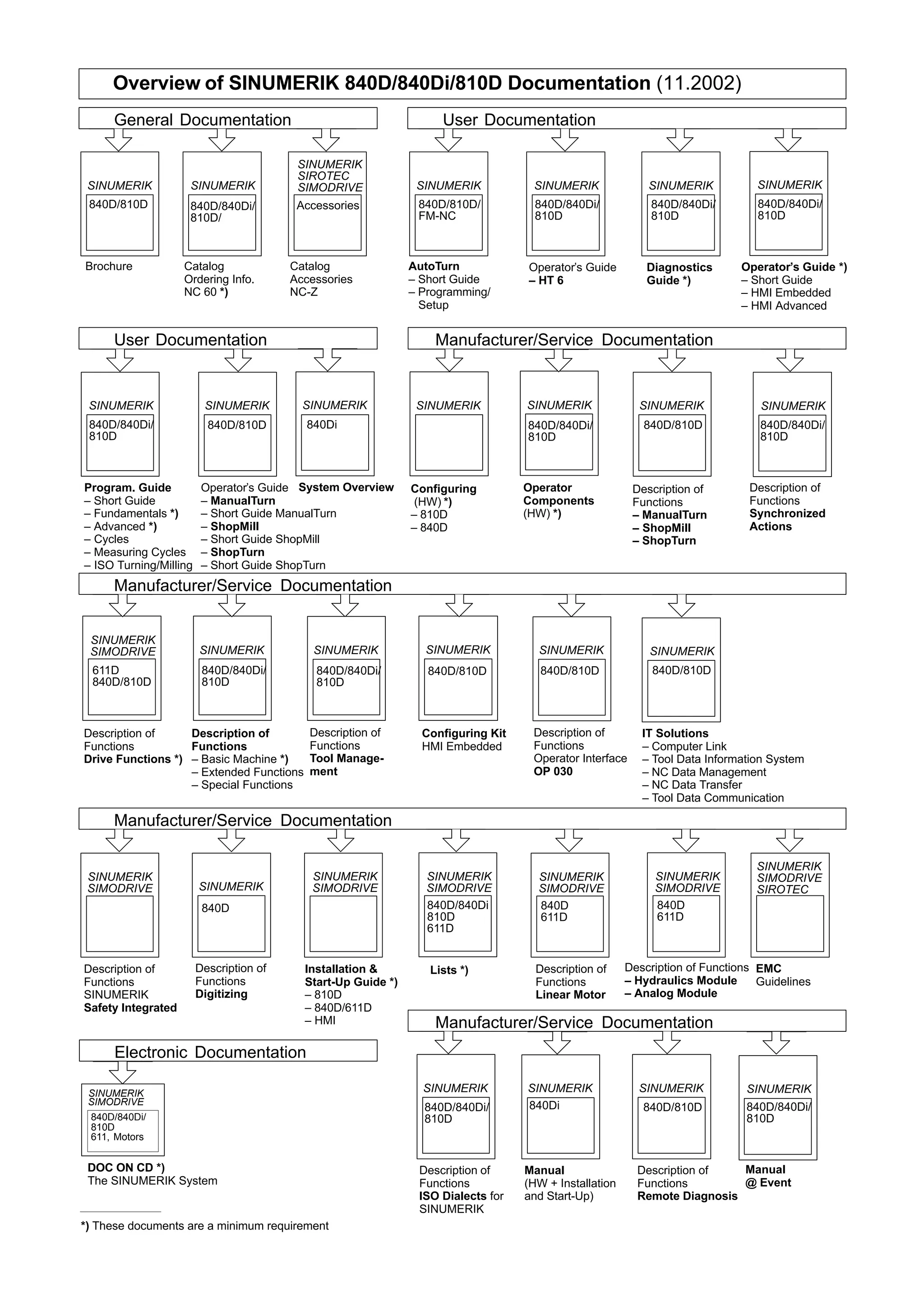


The document is the advanced programming guide for Siemens' Sinumerik 840D, 840DI, and 810D CNC controls, detailing topics such as flexible NC programming, subprograms, macros, file management, and machine commands. It serves as a comprehensive manual for users, covering technical aspects necessary for effective programming and operation of these CNC machines. This edition reflects updates and provides insights into advanced features, functionalities, and best practices.