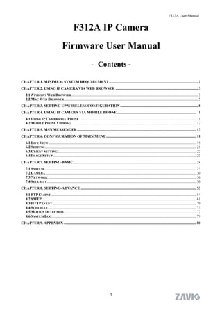
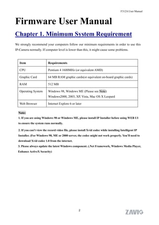
1. The document is a user manual for the F312A IP camera that provides instructions on setting up and using the camera.
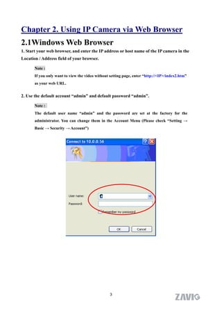
2. It covers connecting to the camera via a web browser on Windows and Mac as well as mobile phones. Settings covered include the network, wireless, motion detection, FTP and more.
3. Chapters are included on basic camera functions like live view, snapshot, zoom as well as advanced configuration in the settings menu.
1. The document provides instructions for installing a wired/wireless IP camera, including installing hardware and software, accessing live video, and troubleshooting common issues.
2. It describes how to set up the ActiveX control to view live video in Internet Explorer and how to perform wireless settings by scanning for available networks and inputting encryption keys.
3. Instructions are given for using dynamic DNS (DDNS) to access the camera remotely over the internet, including registering for a DDNS account, configuring DDNS settings on the camera, changing ports, and setting up port forwarding on the router.
This document provides instructions for setting up and using an IP wireless/wired camera. It describes the camera hardware including features, packing list, product views, and PC system requirements. It also covers hardware installation, software installation including the IP Camera Tool software, and accessing the camera through a web browser. The software operation section explains how to use the IP Camera Tool to find cameras on the network, view camera properties, configure network settings, and upgrade firmware. It also describes how to log into the camera's web interface using different browsers and modes.
ThermoSafety - software pro termovizní monitoringWorkswell s.r.o.
The document discusses installing and setting up Thermo Safety 2013 software. It describes minimum system requirements, recommended hardware including Gigabit Ethernet adapters and switches. The document outlines installing JAI SDK first before Thermo Safety 2013. Activation of a trial or full version requires entering a serial number and email. Connecting a camera involves selecting it from available cameras, clicking connect, then play to start live video acquisition. Sessions and alarms are used to save customized configurations.
This document provides instructions and specifications for an IP camera. It includes:
1. An overview of the IP camera's features such as video compression, viewing capabilities, and applications.
2. Instructions on installing and connecting the IP camera via a LAN or wireless network, and configuring PPPoE settings.
3. Directions for browsing to the IP camera using a web browser and an explanation of basic settings and operations in the interface.
The document provides a comprehensive manual for setting up and using the IP camera on a network. It covers both technical specifications and step-by-step guides for installation, configuration, and operation.
This document provides instructions for setting up and accessing video from an outdoor IP camera. It describes starting up the device and configuring its IP address. It also explains how to access the live video stream locally through a web browser or mobile apps, as well as remotely through the cloud. The technical specifications of the camera are listed at the end.
This document is a user manual for an Intel 845 chipset motherboard supporting Pentium 4 processors. It includes specifications and instructions for hardware installation, BIOS setup, and upgrading the BIOS. The manual provides details on connecting components like memory, fans, audio and I/O ports. It also describes the BIOS features for configuring settings like boot options, integrated peripherals and power management. The motherboard includes a BIOS upgrading utility for easy and secure updating of the BIOS online or from a floppy disk.
This document provides step-by-step instructions for installing and configuring SmartPOS 2.0. Key steps include:
1) Installing required software like Java JDK, restoring ERP and POS databases from backups, and setting up RabbitMQ.
2) Configuring the ERP system by creating a client, loading the chart of accounts, and defining organizations, warehouses, and accounts.
3) Synchronizing key master data between ERP and POS like business partners, products, and payment details using the client and organization IDs.
4) Configuring POS resources like payment and customer IDs to integrate with the ERP system.
This document provides instructions for using the basic features and functions of the Surveon SMR8300 video management system client interface. It explains the main interface elements, how to view live and recorded video, configure motion detection recording, add third-party cameras, perform searches by date, video input, and events, set up user accounts, and configure dual monitors. The document is intended as a simple introduction and refers users to the full SMR8300 user manual for more detailed information and instructions.
This document provides instructions for configuring various settings on a Surveon SMR8300 NVR, including:
1. HDD configuration such as checking the number of installed HDDs and ensuring they meet requirements.
2. RAID configuration such as checking the RAID type and ensuring the minimum number of drives are installed.
3. Configuring network settings such as IP address, enabling the NVR as a DHCP server, and connecting cameras.
4. Configuring other settings such as time zone, users, recording policies, and email notifications. Backup of the system configuration is also recommended.
Digital Watchdog DWC-MV421TIRB User ManualJMAC Supply
Buy the Digital Watchdog DWC-MV421TIRB at JMAC Supply.
https://www.jmac.com/Digital_Watchdog_DWC_MV421TIRB_p/digital-watchdog-dwc-mv421tirb.htm?=slideshare
AccessManager Professional is an access control management program that consists of a server program (AccessServer) and client program (AccessManager). This chapter describes the basic steps for configuring AccessManager Professional which includes registering the administrator in the system.
Digital Watchdog DWC-MD421DB User ManualJMAC Supply
1. The document provides specifications and installation instructions for a Snapit MEGAPIX Indoor Dome Camera. It includes details on lens specifications, network connection options, mounting the camera, accessing the camera remotely, and configuring settings like streaming, recording, and storage.
2. The camera can be set up for internal use on the same network using DHCP or static IP, or for external use over the internet using static IP or DDNS. The IP Finder software helps locate the camera on the network and configure basic settings.
3. Additional features of the camera include auto zoom and focus, motion detection, privacy zones, and local backup storage using an SD card.
The document provides instructions for setting up and using a wireless IP camera. It outlines the steps for hardware setup including plugging in the network and power cables. It describes installing the software by opening the CD, finding the software, and clicking through the installation wizard. The document then explains how to access the camera through the IP Camera Tool software or web browser by entering login credentials. It provides information on software features like panning, tilting, zooming and settings configuration. Finally, it discusses remotely accessing the camera using the router, static IP, or dynamic DNS and addresses some frequently asked questions.
This document provides instructions for configuring the BIG-IP Local Traffic Manager (LTM) with multiple BIG-IP Application Security Manager (ASM) devices to improve performance and scalability. Key steps include creating monitors, pools, and profiles on the LTM and ASM devices, then configuring virtual servers and a security policy. The configuration supports both fail-open and fail-closed modes.
The document provides information about the launch of QRadar Community Edition V7.3.3, including:
- The QRadar Community Edition is now delivered as an OVA file based on QRadar 7.3.3 GA with a smaller footprint for non-enterprise use.
- Support is available through forums only and software updates are not provided.
- Instructions are given for installing the OVA, configuring networking correctly, requirements, and troubleshooting common errors. Ensuring the network configuration meets requirements is critical for a successful installation.
Digital Watchdog DWC-MD421TIRB User ManualJMAC Supply
Buy the Digital Watchdog DWC-MD421TIRB at JMAC Supply.
https://www.jmac.com/Digital_Watchdog_DWC_MD421TIRB_p/digital-watchdog-dwc-md421tirb.htm?=slideshare
The document provides instructions for setting up and using a VIVOTEK network camera test lab. It includes chapters on preparation, installation, using the Installation Wizard 2 software, camera configuration, and using the ST7501 client/server software. Some key points:
- Chapter 1 discusses necessary lab components and how to connect the camera.
- Chapter 2 covers installing the Installation Wizard 2 and ST7501 software, including selecting installation directories and options.
- Chapter 3 describes the Installation Wizard 2 user interface and how it analyzes the network environment.
- Chapter 4 provides steps for configuring camera cropping through the viewing window page to define the region of interest and output frame size.
The document provides operating instructions for Panasonic Network Cameras models BB-HCM381A and BB-HCE481A. It describes the main features of the cameras including:
- Support for IPv6 and IPv4 networks as well as Power over Ethernet (PoE) for model BB-HCE481A.
- Two-way audio communication between the camera and a PC using a connected microphone and speaker.
- Motion detection that can trigger image buffering, transfer to an FTP server, or sending of emails.
- Remote pan, tilt, zoom and focus functions accessible via a web browser.
- Recording of camera images to an SD memory card.
1. The document provides instructions for configuring a Wi-Fi repeater by connecting it to a computer via an Ethernet cable or wirelessly, and describes the different modes (repeater and AP) and settings.
2. It explains how to back up and restore the repeater's settings, upgrade its firmware, and change the management password.
3. Additional information is provided on adding computers to the repeater's wireless network through WPS or by manually configuring the computer's network settings.
This document provides a user guide for a network camera, outlining its features such as simple installation, remote monitoring capabilities, video recording, alarm functions, and setup instructions. Chapters cover product introduction, installation, searching for and logging into the camera, video and PTZ settings, system settings, recording, alarms, controls, diagnostics, logout procedures, and accessing the camera via WAN or mobile phone.
Windows 2000/XP/Vista/7
IE Browser: IE5.0 or above
Recommended Hardware Configuration
CPU: Pentium 3.0 GHz or above
Memory: 512MB or above
Hard Disk: 80G or above
Operation System: Windows 2000/XP/Vista/7
IE Browser: IE6.0 or above
2. Interface & Installation
2.1. Interface
The interface of IP camera is shown as below:
1. Network interface: RJ-45 interface, connect to network cable.
2. Power interface: DC power interface, connect to power adapter.
3. Reset button: long press reset button for 10 seconds to restore
Here are the steps to add multiple cameras:
1. Click "Refresh" button to search cameras connected to the same LAN. The searched cameras will be displayed in the device list.
2. Select the camera you want to add and click "Add" button. The camera will be added to the added device list.
3. You can add up to 4 cameras. Once 4 cameras are added, the "Add" button will become inactive.
4. To view streams from the added cameras, go to the live view page. Their streams will be displayed in the additional windows.
5. To remove a camera, select it from the added device list and click "Delete".
So in summary
This document provides instructions for installing IBM Informix Client Software Development Kit (Client SDK) and IBM Informix Connect on UNIX, Linux, Mac OS X, and Windows systems. It describes preparing for installation, running the installation program in different modes, and post-installation configuration. The document also covers uninstalling the client products and distributing them with custom applications.
The document provides an overview and instructions for a D-Link network camera. It includes:
1) A list of package contents and system requirements for using the camera.
2) An introduction describing the camera's features like day/night functionality, 0.5 lux light sensitivity, and H.264 video compression.
3) A table of contents organizing the manual's sections on configuration, setup, live video, and maintenance.
The document provides instructions for configuring cameras for use with the myABELL system. It describes installing cameras on the local network, configuring port forwarding on the router, and adding cameras to the myABELL system. Specific camera models like Axis and Vivotek require only the generic installation steps, while other unsupported cameras need a URL provided to access images. The myABELL configuration page requires location, user credentials, ports and IP addresses be specified to connect cameras.
This document provides instructions for configuring the NVR3000 video recorder, including steps for initial disk, RAID, network, camera, time, and user configuration. It also covers adding cameras, email notification setup, backup configuration, and answers questions about high quality viewing modes. The configuration process involves checking disk numbers, selecting a RAID level, setting the network and IP settings, adding cameras in simple or advanced mode, setting the correct time zone, creating user accounts, setting the recording policy, and backing up the system configuration.
The document provides setup instructions for deploying and configuring an Aruba Instant wireless network. It describes how to set up the initial access point which will run the virtual controller software. Additional access points will automatically inherit settings from the virtual controller. The instructions also cover creating basic employee and guest wireless networks with options for security, client IP assignment, and access controls. The process involves a simple four step configuration for each network's basic info, IP settings, security, and access rules.
This document provides step-by-step instructions for configuring the Kerio WinRoute Firewall version 6.7 to set up the local network and headquarters configuration for a company. It describes selecting IP addresses for the LAN, configuring the network interfaces for the internet gateway and LAN, installing WinRoute, setting up basic traffic policies, DHCP server, DNS, user accounts and groups, access rules, VPN connectivity between headquarters and branch offices, and more. The configuration guides a realistic network example and addresses all essential aspects for deploying WinRoute in a company network.
This document provides information about a capstone networking project, including hardware, software, network configuration, installing Windows Server 2012, installing a VPN and firewall, network protocols, IP addressing, and hardware and software security and backup. The hardware includes domain controllers, client computers, routers, switches, and servers. The software includes programs like Microsoft Office, Exchange, PowerShell, and operating systems like Windows and Windows Server. Details are provided about setting up a domain network and workgroup network, and configuring DNS, DHCP, and active directory on the Windows Server 2012 domain controller. Steps for installing a VPN and configuring a firewall are also outlined. Networking protocols, IP addressing schemes, and concepts of public vs private IP classes and subnet
This document provides instructions for operating a WiFi network camera. The camera can be monitored after following 4 steps: 1) Download the mobile app, 2) Connect phone to camera WiFi hotspot, 3) Press the reset button on the camera for 30 seconds, 4) Log into the camera on the mobile app. Key parameters of the camera include support for VGA video resolution, 10fps frame rate, CMOS sensor, 2.4GHz WiFi, and operation via mobile or computer app.
Mikrotik Network Simulator (MUM Presentation Material 2013)Rofiq Fauzi
Rofiq Fauzi presented on creating a MikroTik network simulator using GNS3. He discussed how to install MikroTik RouterOS as a virtual machine using Qemu, add it to GNS3, and connect it to the host computer via a loopback interface to allow remote management. This allows testing of MikroTik features and network topologies without requiring physical hardware. Each additional MikroTik router added to GNS3 increases memory usage by approximately 80MB, allowing planning of resource requirements. Fauzi demonstrated the process and configuration steps to set up the simulator.
Safe peak installation guide version 2.1Vladi Vexler
This document provides instructions for installing SafePeak, a software that accelerates data access for Microsoft SQL Server. It discusses minimum system requirements, how to install SafePeak, adding a license, configuring SQL database instances, connecting applications, and configuring dynamic objects and SQL patterns. The installation process involves choosing an installation type and location, setting up a virtual IP address, adding the SafePeak license, providing login credentials, and adding SQL database instances. Dynamic objects and non-deterministic SQL queries may require additional configuration for optimal caching.
Observability Concepts EVERY Developer Should Know -- DeveloperWeek Europe.pdfPaige Cruz
Monitoring and observability aren’t traditionally found in software curriculums and many of us cobble this knowledge together from whatever vendor or ecosystem we were first introduced to and whatever is a part of your current company’s observability stack.
While the dev and ops silo continues to crumble….many organizations still relegate monitoring & observability as the purview of ops, infra and SRE teams. This is a mistake - achieving a highly observable system requires collaboration up and down the stack.
I, a former op, would like to extend an invitation to all application developers to join the observability party will share these foundational concepts to build on:
Generative AI Deep Dive: Advancing from Proof of Concept to ProductionAggregage
Join Maher Hanafi, VP of Engineering at Betterworks, in this new session where he'll share a practical framework to transform Gen AI prototypes into impactful products! He'll delve into the complexities of data collection and management, model selection and optimization, and ensuring security, scalability, and responsible use.
UiPath Test Automation using UiPath Test Suite series, part 6DianaGray10
Welcome to UiPath Test Automation using UiPath Test Suite series part 6. In this session, we will cover Test Automation with generative AI and Open AI.
UiPath Test Automation with generative AI and Open AI webinar offers an in-depth exploration of leveraging cutting-edge technologies for test automation within the UiPath platform. Attendees will delve into the integration of generative AI, a test automation solution, with Open AI advanced natural language processing capabilities.
Throughout the session, participants will discover how this synergy empowers testers to automate repetitive tasks, enhance testing accuracy, and expedite the software testing life cycle. Topics covered include the seamless integration process, practical use cases, and the benefits of harnessing AI-driven automation for UiPath testing initiatives. By attending this webinar, testers, and automation professionals can gain valuable insights into harnessing the power of AI to optimize their test automation workflows within the UiPath ecosystem, ultimately driving efficiency and quality in software development processes.
What will you get from this session?
1. Insights into integrating generative AI.
2. Understanding how this integration enhances test automation within the UiPath platform
3. Practical demonstrations
4. Exploration of real-world use cases illustrating the benefits of AI-driven test automation for UiPath
Topics covered:
What is generative AI
Test Automation with generative AI and Open AI.
UiPath integration with generative AI
Speaker:
Deepak Rai, Automation Practice Lead, Boundaryless Group and UiPath MVP
Introducing Milvus Lite: Easy-to-Install, Easy-to-Use vector database for you...Zilliz
Join us to introduce Milvus Lite, a vector database that can run on notebooks and laptops, share the same API with Milvus, and integrate with every popular GenAI framework. This webinar is perfect for developers seeking easy-to-use, well-integrated vector databases for their GenAI apps.
In the rapidly evolving landscape of technologies, XML continues to play a vital role in structuring, storing, and transporting data across diverse systems. The recent advancements in artificial intelligence (AI) present new methodologies for enhancing XML development workflows, introducing efficiency, automation, and intelligent capabilities. This presentation will outline the scope and perspective of utilizing AI in XML development. The potential benefits and the possible pitfalls will be highlighted, providing a balanced view of the subject.
We will explore the capabilities of AI in understanding XML markup languages and autonomously creating structured XML content. Additionally, we will examine the capacity of AI to enrich plain text with appropriate XML markup. Practical examples and methodological guidelines will be provided to elucidate how AI can be effectively prompted to interpret and generate accurate XML markup.
Further emphasis will be placed on the role of AI in developing XSLT, or schemas such as XSD and Schematron. We will address the techniques and strategies adopted to create prompts for generating code, explaining code, or refactoring the code, and the results achieved.
The discussion will extend to how AI can be used to transform XML content. In particular, the focus will be on the use of AI XPath extension functions in XSLT, Schematron, Schematron Quick Fixes, or for XML content refactoring.
The presentation aims to deliver a comprehensive overview of AI usage in XML development, providing attendees with the necessary knowledge to make informed decisions. Whether you’re at the early stages of adopting AI or considering integrating it in advanced XML development, this presentation will cover all levels of expertise.
By highlighting the potential advantages and challenges of integrating AI with XML development tools and languages, the presentation seeks to inspire thoughtful conversation around the future of XML development. We’ll not only delve into the technical aspects of AI-powered XML development but also discuss practical implications and possible future directions.
GraphSummit Singapore | The Art of the Possible with Graph - Q2 2024Neo4j
Neha Bajwa, Vice President of Product Marketing, Neo4j
Join us as we explore breakthrough innovations enabled by interconnected data and AI. Discover firsthand how organizations use relationships in data to uncover contextual insights and solve our most pressing challenges – from optimizing supply chains, detecting fraud, and improving customer experiences to accelerating drug discoveries.
Enchancing adoption of Open Source Libraries. A case study on Albumentations.AIVladimir Iglovikov, Ph.D.
Presented by Vladimir Iglovikov:
- https://www.linkedin.com/in/iglovikov/
- https://x.com/viglovikov
- https://www.instagram.com/ternaus/
This presentation delves into the journey of Albumentations.ai, a highly successful open-source library for data augmentation.
Created out of a necessity for superior performance in Kaggle competitions, Albumentations has grown to become a widely used tool among data scientists and machine learning practitioners.
This case study covers various aspects, including:
People: The contributors and community that have supported Albumentations.
Metrics: The success indicators such as downloads, daily active users, GitHub stars, and financial contributions.
Challenges: The hurdles in monetizing open-source projects and measuring user engagement.
Development Practices: Best practices for creating, maintaining, and scaling open-source libraries, including code hygiene, CI/CD, and fast iteration.
Community Building: Strategies for making adoption easy, iterating quickly, and fostering a vibrant, engaged community.
Marketing: Both online and offline marketing tactics, focusing on real, impactful interactions and collaborations.
Mental Health: Maintaining balance and not feeling pressured by user demands.
Key insights include the importance of automation, making the adoption process seamless, and leveraging offline interactions for marketing. The presentation also emphasizes the need for continuous small improvements and building a friendly, inclusive community that contributes to the project's growth.
Vladimir Iglovikov brings his extensive experience as a Kaggle Grandmaster, ex-Staff ML Engineer at Lyft, sharing valuable lessons and practical advice for anyone looking to enhance the adoption of their open-source projects.
Explore more about Albumentations and join the community at:
GitHub: https://github.com/albumentations-team/albumentations
Website: https://albumentations.ai/
LinkedIn: https://www.linkedin.com/company/100504475
Twitter: https://x.com/albumentations
TrustArc Webinar - 2024 Global Privacy SurveyTrustArc
How does your privacy program stack up against your peers? What challenges are privacy teams tackling and prioritizing in 2024?
In the fifth annual Global Privacy Benchmarks Survey, we asked over 1,800 global privacy professionals and business executives to share their perspectives on the current state of privacy inside and outside of their organizations. This year’s report focused on emerging areas of importance for privacy and compliance professionals, including considerations and implications of Artificial Intelligence (AI) technologies, building brand trust, and different approaches for achieving higher privacy competence scores.
See how organizational priorities and strategic approaches to data security and privacy are evolving around the globe.
This webinar will review:
- The top 10 privacy insights from the fifth annual Global Privacy Benchmarks Survey
- The top challenges for privacy leaders, practitioners, and organizations in 2024
- Key themes to consider in developing and maintaining your privacy program
Communications Mining Series - Zero to Hero - Session 1DianaGray10
This session provides introduction to UiPath Communication Mining, importance and platform overview. You will acquire a good understand of the phases in Communication Mining as we go over the platform with you. Topics covered:
• Communication Mining Overview
• Why is it important?
• How can it help today’s business and the benefits
• Phases in Communication Mining
• Demo on Platform overview
• Q/A
How to Get CNIC Information System with Paksim Ga.pptxdanishmna97
Pakdata Cf is a groundbreaking system designed to streamline and facilitate access to CNIC information. This innovative platform leverages advanced technology to provide users with efficient and secure access to their CNIC details.
Climate Impact of Software Testing at Nordic Testing DaysKari Kakkonen
My slides at Nordic Testing Days 6.6.2024
Climate impact / sustainability of software testing discussed on the talk. ICT and testing must carry their part of global responsibility to help with the climat warming. We can minimize the carbon footprint but we can also have a carbon handprint, a positive impact on the climate. Quality characteristics can be added with sustainability, and then measured continuously. Test environments can be used less, and in smaller scale and on demand. Test techniques can be used in optimizing or minimizing number of tests. Test automation can be used to speed up testing.
Goodbye Windows 11: Make Way for Nitrux Linux 3.5.0!SOFTTECHHUB
As the digital landscape continually evolves, operating systems play a critical role in shaping user experiences and productivity. The launch of Nitrux Linux 3.5.0 marks a significant milestone, offering a robust alternative to traditional systems such as Windows 11. This article delves into the essence of Nitrux Linux 3.5.0, exploring its unique features, advantages, and how it stands as a compelling choice for both casual users and tech enthusiasts.
20 Comprehensive Checklist of Designing and Developing a WebsitePixlogix Infotech
Dive into the world of Website Designing and Developing with Pixlogix! Looking to create a stunning online presence? Look no further! Our comprehensive checklist covers everything you need to know to craft a website that stands out. From user-friendly design to seamless functionality, we've got you covered. Don't miss out on this invaluable resource! Check out our checklist now at Pixlogix and start your journey towards a captivating online presence today.
“An Outlook of the Ongoing and Future Relationship between Blockchain Technologies and Process-aware Information Systems.” Invited talk at the joint workshop on Blockchain for Information Systems (BC4IS) and Blockchain for Trusted Data Sharing (B4TDS), co-located with with the 36th International Conference on Advanced Information Systems Engineering (CAiSE), 3 June 2024, Limassol, Cyprus.
2. F312A User Manual
F312A IP Camera
Firmware User Manual
- Contents -
CHAPTER 1. MINIMUM SYSTEM REQUIREMENT............................................................................................... 2
CHAPTER 2. USING IP CAMERA VIA WEB BROWSER ........................................................................................ 3
2.1WINDOWS WEB BROWSER....................................................................................................................................... 3
2.2 MAC WEB BROWSER............................................................................................................................................... 5
CHAPTER 3. SETTING UP WIRELESS CONFIGURATION ................................................................................... 8
CHAPTER 4. USING IP CAMERA VIA MOBILE PHONE..................................................................................... 11
4.1 USING IP CAMERA VIA IPHONE ............................................................................................................................. 11
4.2 MOBILE PHONE VIEWING ..................................................................................................................................... 12
CHAPTER 5. MSN MESSENGER............................................................................................................................... 13
CHAPTER 6. CONFIGURATION OF MAIN MENU................................................................................................ 18
6.1 LIVE VIEW ............................................................................................................................................................. 19
6.2 SETTING ................................................................................................................................................................. 21
6.3 CLIENT SETTING ................................................................................................................................................... 22
6.4 IMAGE SETUP......................................................................................................................................................... 23
CHAPTER 7. SETTING-BASIC................................................................................................................................... 24
7.1 SYSTEM .................................................................................................................................................................. 25
7.2 CAMERA ................................................................................................................................................................. 30
7.3 NETWORK .............................................................................................................................................................. 36
7.4 SECURITY ............................................................................................................................................................... 50
CHAPTER 8. SETTING-ADVANCE ........................................................................................................................... 53
8.1 FTP CLIENT ........................................................................................................................................................... 54
8.2 SMTP .................................................................................................................................................................... 61
8.3 HTTP EVENT ......................................................................................................................................................... 70
8.4 SCHEDULE.............................................................................................................................................................. 75
8.5 MOTION DETECTION ............................................................................................................................................. 77
8.6 SYSTEM LOG .......................................................................................................................................................... 79
CHAPTER 9. APPENDIX ............................................................................................................................................. 80
1
3. F312A User Manual
Firmware User Manual
Chapter 1. Minimum System Requirement
We strongly recommend your computers follow our minimum requirements in order to use this
IP-Camera normally. If computer level is lower than this, it might cause some problems.
Item Requirements
CPU Pentium 4 1600MHz (or equivalent AMD)
Graphic Card 64 MB RAM graphic cards(or equivalent on-board graphic cards)
RAM 512 MB
Operating System Windows 98, Windows ME (Please see Note)
Windows2000, 2003, XP, Vista, Mac OS X Leopard
Web Browser Internet Explore 6 or later
Note:
1. If you are using Windows 98 or Windows ME, please install IP Installer before using WEB UI
to ensure the system runs normally.
2. If you can't view the record video file, please install Xvid codec while installing Intelligent IP
Installer. (For Windows 98, ME or 2000 server, the codec might not work properly. You’ll need to
download Xvid codec 1.0 from the internet.
3. Please always update the latest Windows component. (.Net Framework, Windows Media Player,
Enhance ActiveX Security)
2
4. Chapter 2. Using IP Camera via Web Browser
2.1Windows Web Browser
1. Start your web browser, and enter the IP address or host name of the IP camera in the
Location / Address field of your browser.
Note :
If you only want to view the video without setting page, enter “http://<IP>/index2.htm”
as your web URL.
2. Use the default account “admin” and default password “admin”.
Note :
The default user name “admin” and the password are set at the factory for the
administrator. You can change them in the Account Menu (Please check “Setting →
Basic → Security → Account”)
3
5. 3. The monitor image will be displayed in your browser. In the far left side of main
configuration are Setting, Client Setting, and Image Setup. For more details, you can check
Chapter 6.2、Chapter 6.3 and Chapter 6.4.
4
6. 2.2 Mac Web Browser
1. Click the Safari icon, and enter the IP address of the IP camera in the Location / Address
field of your browser.
Note :
If you only want to view the video without setting page, enter “http://<IP>/index2.htm”
as your web URL.
5
7. 2. Use the default account “admin” and default password “admin”.
Note :
The default user name “admin” and the password are set at the factory for the
administrator. You can change them in the Account Menu (Please check “Setting →
Basic → Security → Account”)
6
8. 3. The monitor image will be displayed in your browser. In the far left side of main
configuration are Setting, Client Setting, and Image Setup. For more details, you can check
Chapter 6.2、Chapter 6.3 and Chapter 6.4.
7
9. Chapter 3. Setting up Wireless Configuration
The wireless network has to be set up by using cable network connection. After setting the
camera correctly, the wireless function can work without cable network connection. Please follow
the setting process below step by step:
1. Connect IP Camera with Ethernet connection. (Check chapter 7.3.6 for more details)
2.Go to Setting → Basic → Network → Wireless choose option “On”. You will see the
wireless setting page.
2. Go to “Setting→Basic→Network→Wireless", set the Wireless option to “ON” .
3. Then click “Refresh”. All access points (AP) around you will show up.
8
10. 4. Select the AP you wish to connect.
5. Enter password at active transmit key if you need. If you don't know the setting of the
wireless AP, please ask your network administrator.
6. Choose the option of Obtain an IP address automatically (DHCP).
7. Choose the option of Obtain DNS server address automatically.
9
11. Use the following IP address: Select this when the fixed IP address is set.
IP address: Enter the IP address of the device.
Subnet mask: Enter the subnet mask.
Default gateway: Enter the default gateway.
Use the following DNS server address: Select this when you set the fixed address as the
IP address of DNS server.
Primary DNS server: Enter the IP address of the primary DNS server.
Secondary DNS server: Enter the IP address of the secondary DNS server, if
necessary.
8. Connect to the IP camera with wireless IP address, then you can remove the Ethernet
connection.
10
12. Chapter 4. Using IP Camera via Mobile Phone
4.1 Using IP Camera via iPhone
You can use Zavio Web User Interface via iPhone. Please follow the setting process below.
Then you can use Zavio web UI via iPhone.
1. Select Safari function 2. Enter IP address in your web link.
3. Type name and password. 4. The Zavio User Interface and live
Default value is admin / admin. image will show up in the middle of
Then click Login In screen.
Note: It will show continuous snapshots not
a real time video streaming. Therefore, the
recording feature is disabled.
11
13. 4.2 Mobile Phone Viewing
To use IP cameras via mobile phones, please make sure your RTSP is set to “On” (Default is
“On”). To change the settings of IP cameras, Please check “Settings → Basic → Camera →
General.”
1. 3G Mobile Phone Streaming Viewing
For 3G mobile phone viewing, type “ rtsp://<IP>:<PORT>/video.3gp ” into your 3G
Streaming Link. <IP> is the Public IP address of your IP camera; <PORT> is the RTSP port
of your IP camera (Default value is 554.) Example: rtsp://100.10.10.1:554/video.3gp
Note: You can also use RTSP clients (RealPlayer, VLC, QuickTime Player…etc.) to
view RTSP streaming, just type in “rtsp://<IP>:<PORT>/video.3gp” as the Player URL
2. 2.5G Mobile Phone WAP Viewing
For 2.5G mobile phone viewing, type “ <IP>/mobile.wml ” into your 2.5G WAP Browser.
<IP> is the Public IP address of your IP camera.
3. 2.5G Mobile Phone Browser Viewing
For 2.5G mobile phone viewing, type “ <IP>/mobile.htm ” into your 2.5G Web Browser.
<IP> is the Public IP address of your IP camera.
12
14. Chapter 5. MSN Messenger
Please see the following steps to set up the Messenger function.
1. You can download MSN software freely and create a new MSN account (camera at home) to
use Microsoft Live Messenger.
2.Go to Setting→Basic→Network→Messenger , set the Messenger to “ON” . Then, login in new
account and password (Camera at home).
3. Choose “On” at the option of IP Notification. If this feature switches On, camera will send
IP notification to the users who are allowed.
4. Choose “On” at the option of Privacy. If you can choose “On” at the privacy option, you can set
an allow list.
5. Use your account to login in the Messenger software. Then, add the new MSN account (Camera
at home )
13
15. 6. The Camera at home will show up with its Public IP and Private IP if the option of IP
Notification is “On”. ( You can enter “Ping” to show up with Public IP and Private IP. )
7. Click on the small camera icon . Then, choose “View a new contact's webcam”.
Camera at home says:
8. The IP Camera will accept your invitation; the live video will show up in the right screen after
few seconds.
14
16. 9. Click Action button and choose Start control panel to use control panel.
10. The dialog box will show up with “This application is not part if Window Live Message…….”
Tick the box of “Don’t show me this again” and click OK
15
17. 11. The IP Camera will accept your invitation to start Control Panel.
12. You can click Camera icon to snapshot then the picture will send to you immediately.
Snapshot
16
18. 13. You can click paint palette icon showing up with tool bar to set up image. Then, you
can use the tool bar to optimize video Brightness , Contrast , Saturation and Hue .
After the adjustment of all setting, you can still click to make the setting back to the
original setting.
Image Setup
17
19. Chapter 6. Configuration of Main Menu
In the far left side of main configuration are Setting, Client Setting, Image Setup. For more
details, you can check Chapter 6.2、Chapter 6.3、Chapter 6.4.
Snapshot
Full screen
Zoom in / Out
Video Play Audio button
In your right hand side, you can use Live View in your main Browser. There are Snapshot,
Zoom and Audio and Video Play four different function. You can see more details as follow.
18
20. 6.1 Live View
A. Snapshot
You can capture a still image shot by the camera and save it in your computer.
Symbols Meaning
a snapshot window will appear
Save to save the picture in your computer
Close to return to the view page
full Screen
B. Zoom in / out the image via the monitor window
Click to display the digital zoom in window.
Pull the to adjust the digital zoom range, and it will
be showed on the above window.
You can use the left click of your mouse to move the to any where on the window.
19
21. C. Video play buttons
Symbols Meaning
Pause the current video
Play the video
Stop the current video
Record the current video
Note:
Concerning the recording storage requirement of your hard disk, please refer to
the CHAPTER 9. APPENDIX / B. Storage Requirement Table.
D. Audio buttons
Symbols Meaning Note
mean the speakers of your computer are
Speakers turned on turned on to transmit the sounds from the
connected IP camera(s)
Speakers turned off
mean you can broadcast to the connected
Microphone turned on IP camera(s) via the Ethernet using your
microphone
Microphone turned off
Volume control bar
20
22. 6.2 Setting
This function is only for the Administrator. Click this button to get into the Basic and
Advance settings menu.
Click Basic folder, there are four sub-folders including System, Camera, Network, and
Security. Fore more information, you can see Chapter 7.1、Chapter 7.2、Chapter 7.3
and Chapter 7.4.
Click Advance folder, there are four sub-folders including FTP Client, SMTP, HTTP
event, Schedule, Motion Detection, and System Log. Fore more information, you can
see Chapter 8.1、Chapter 8.2、Chapter 8.3、Chapter 8.4、Chapter 8.5 and Chapter 8.6.
21
23. 6.3 Client Setting
This function is only for the client.
Click this button to control Mode, View Size, Protocol, and Video Buffer.
6.3.1 Mode
Click the pull-down box to choose between MPEG4 and MJPEG video compression mode.
MJPEG streaming is unavailable if RTSP mode is “On.”
(Please check Setting → Basic → Camera → General)
Note:MJPEG streaming is unavailable if RTSP mode is On.
6.3.2 View Size
Select the desired display image resolution to 640X480 or 320X240.
6.3.3 Protocol
Select the transferring protocol from TCP, UDP, HTTP and Multicast.
6.3.4 Video Buffer
Turn the Video Buffer function ON / OFF. The Video Buffer function makes the streaming
more smoothly in unsteady network environment, but might cause a little delay in live
viewing.
22
24. 6.4 Image Setup
You can use the tool bar to optimize video Brightness, Contrast, Saturation and Hue.
6.4.1 Brightness
The higher value the brightness is, the brighter the image is.
6.4.2 Contrast
The contrast is a measure of a display system, defined as the ratio of white to black that the
system is capable of producing. The higher value the contrast is, the more delicate of color you
can have.
6.4.3 Saturation
The saturation of a color is determined by a combination of light intensity and how much it is
distributed across the spectrum of different wavelengths. The higher value the saturation is, the
more colorful the image will be.
5.4.4 Hue
Hue is one of the three main attributes of perceived color, affected by different wavelength of
color. With higher value of hue, color will be much more vivid.
6.4.5 Default
After the adjustment of all setting, you can still click Default to make the setting back to the
original setting.
23
25. Chapter 7. Setting-Basic
Click the folder of Basic to display the sub folders including System, Camera, Network, and
Security.
24
26. 7.1 System
Click the folder of System to display the sub-folders including Information, Date / Time,
and Initialize.
25
27. 7.1.1 Information
The Information page provides the product factory information which includes Product
Name, Firmware Version and Web Version.
26
28. 7.1.2 Date / Time
The Date/ Time page displays all options of time setting.
Current date / time: This displays the current date and time of this IP Camera.
PC clock: This displays the date and time of the monitoring PC clock.
Date / Time format: You can click the pull down box to select different time display
formats.
Adjust: You can select one of those four adjusting modes for your IP Camera.
Keep current setting: Select this mode to keep the current date and time of this IP
Camera.
Synchronize: Select this mode to keep the date and time of this IP Camera is the same
as the monitoring PC.
Manual setting: Select this mode to adjust manually the date and time of this IP
Camera.
Synchronize with NTP: Specify the NTP server name and the Refresh Interval to
synchronize the date and time of this IP Camera with those of the time server, known
as the NTP server.
Time Zone: You can select the Time Zone of the format from Greenwich Mean Time.
The time will display the same as the current date / time option.
Note:
The NTP server (Network Time Protocol) is the time server which is an Internet
standard protocol built on the top of TCP / IP. This assures accurate synchronization to
the millisecond of computer clock times in a network of computers.
27
29. 7.1.3 Initialize
Reboot: Click this bottom to reboot this IP Camera. A confirmation dialogue will appear
and then click “OK” to process. It takes two minutes to reboot this IP Camera.
Factory Default: Click this bottom to reset this IP Camera to the factory default setting.
A confirmation dialogue will appear and then click “OK” to process. The network indicator
on this IP Camera will start to blink. This IP Camera will reboot automatically after
completing adjustments to the default setting. Don't turn off this IP Camera until the device
reboots.
Backup Setting: You can save the setting data of this IP Camera into a file. Click “Save”
and follow the instructions on the browser to save the setting data file to your specified
location.
Restore Setting: Download the saved setting data of this IP Camera. Click “Browse” and
select saved file. Click “OK” and this IP Camera is adjusted according to the loaded data
and then restarted.
Firmware Update: Upgrade the device software. Click “Browse” and select the file for
upgrading. A confirmation dialogue will appear. Click “OK” to start upgrading. This IP
Camera will reboot upon completion.
Note:
Use only upgrade files that are special for this IP Camera. Otherwise problems may
occur. Don't turn off the IP Camera power or disconnect the network until the
upgrading is completed.
28
30. Upload Language Pack: Upgrade the device language pack. Click “Browse” and select
the file for upgrading. A confirmation dialogue will appear. Click “OK” to start upgrading.
The upgrade is applied immediately. The default language is “English.”
29
31. 7.2 Camera
Click the folder of Camera to display the sub folders including General, MPEG4 and
MJPEG.
30
32. 7.2.1 General
RTSP : Switch On / Off
Note: RTSP (Real Time Streaming Protocol) is a protocol for use in streaming
media system which allows clients to remotely control a streaming video server.
RTSP is supports by most of the media clients such as Real Player, QuickTime
and VLC...etc.
Image Rotate: You can mirror or flip the display screen.
Night Mode: You can choose Auto / Off. If you choose Auto option, the camera will
adjust automatically to perform well when the environment is dark
Lighting: You can choose the environment among 50 Hz, 60 Hz , and Outdoor.
White Balance: You can choose the white balance to Auto, Florescent, Incandescent and
Black & White.
IR: You can turn LEDs light On / Off and Auto. If you select Auto mode, you can adjust
threshold for LEDs Auto-On and Auto-Off respectively. In the right hand side of threshold,
if the tool bar is closer to the right, the LEDs will auto-on easily in the dark environment.
Conversely, in the left hand side of threshold, if the tool bar is more approach to the left, the
LEDs will auto-off easily in the bright environment.
Overlay:
Text Overlay: You can see some information on the display screen which includes
Date / Time and user-defined text. Also, you can change the background color.
Privacy Mask: You can cover a specific area of the video image.
31
33. 7.2.2MPEG4
A. Computer View
RTSP (if RTSP mode is On, please check “Setting → Basic → Camera → General ”)
RTSP Port: Specify the transmission port number of RTSP streaming. The default
value is 8554.
Viewer Authentication: If the viewer authentication is On, the users will be requested
to key-in username and password when viewing through RTSP.
RTP (if RTSP mode is On, please check “Basic→ Camera → General“)
Unicast Streaming Video / Audio Port Range: Specify the transmission port range of
RTP streaming video. RTP will select a port randomly from the range.
Multicast Streaming (If it is ON)
Multicast Address: Specify the multicast server address.
Video / Audio Port: Specify the transmission port number of the video data. Specify
an even number from 1024 to 65534.
Time to Live: Set the maximum TTL that multicast can pass through.
Image Size: Specify the image size when the network camera transmits. You can choose
among 640 x 480, 320 x 240, and 160 x 120.
Frame Rate: Set the frame rate of the MPEG4 image. You can choose values from 5, 10,
15, 20, 25, and 30 fps. The unit “fps” stands for “frames per second”.
Quality:
Auto: The quality and bitratee will be adjusted automatically according to the frame
rate.
Fixed Quality: You can select the value of quality among Medium, Good, Delicate
32
34. and Excellent.
Fixed Bitrate: Set the bitrate of MPEG4 image transmission for a line. You can select
the values from 64, 128, 256, 384, 512, 768, 1024, 1280, 1536, and 2048 kbps.
MPEG4 view port (if RTSP mode is Off, please check “Basic → Camera →
General”)
Unicast Streaming Video / Audio Port Number: Specify the transmission port
number of the video data. It is initially set to 8090. You can specify an even number
from 1024 to 65534. If you change the setting of Video / Audio Port Number, the
setting of Video / Audio Port Number (SSL) will change automatically.
Note:
Concerning how to select the suitable image quality for Fixed Quality or Fixed Bitrate, please
refer to the CHAPTER 9. APPENDIX / A. Frame-rate & Bitrate Table.
33
35. B. Mobile View
RTSP (if RTSP mode is On, please check “Setting → Basic → Camera → General”)
RTSP Port: Specify the transmission port number of RTSP streaming. The default
value is 554.
RTP (if RTSP mode is On, please check “Setting → Basic → Camera → General”)
Unicast Streaming Video / Audio Port Range: Specify the transmission port range of
RTP streaming video. RTP will select a port randomly from the range.
Multicast Streaming (If it is On)
Multicast Address: Specify the multicast server address.
Video / Audio Port: Specify the transmission port number of the video data. It is
initially set to 10000 and 11000. Specify an even number from 1024 to 65534.
Time to Live: Set the maximum TTL that multicast can pass through.
Image Size: The image size of Mobile View is fixed at 160 x 120.
Frame Rate: Set the frame rate of the MPEG4 image. You can choose values from 5, 10,
15, 20 fps. The unit “fps” stands for “frames sent per second”.
Quality:
Fixed Bitrate: Set the bitrate of MPEG4 image transmission for a line. You can select
the value from 64, 32, 16 kbps.
Note:
Concerning how to select the suitable image quality for Fixed Quality or Fixed Bitrate, please
refer to the CHAPTER 9. APPENDIX / A. Frame-rate & Bitrate Table.
34
36. 7.2.3 MJPEG
MJPEG Viewer Port( If RTSP is off, please check “Setting → Basic → Camera →
General”):
Unicast Streaming Video / Audio Port Number: Specify the transmission port number
of the video data. It is initially set to 8070. You can specify an even number from 1024
to 65534. If you change the setting of Video / Audio Port Number, the setting of Video
/ Audio Port Number (SSL) will change automatically.
Image Size: Specify the image size when the network camera transmits. You can choose
among 640 x 480, 320 x 240, and 160 x 120.
Frame Rate: Set the frame rate of the MJPEG image. You can choose values from 5, 10,
15 fps. The unit “fps” stands for “frames per second”.
Quality:
Auto: The quality will be automatically decided.
Fixed Quality: You can select the value of quality among Medium, Standard, Good,
Delicate and Excellent.
Note:
Concerning how to select the suitable image quality for Fixed Quality or Fixed Bitrate, please
refer to the CHAPTER 9. APPENDIX / A. Frame-rate & Bitrate Table.
35
37. 7.3 Network
Click the folder of Network to display the sub folders including Information, PPPoE,
DDNS, UPnP, Bonjour, IP Notification, and Messenger.
36
38. 7.3.1 Information
Display the MAC address of the device.
Obtain an IP address automatically (DHCP): If a DHCP server is installed on the
network, to select this while the IP address is assigned by the DHCP server.
Obtain DNS server address automatically: Select this to obtain the address of DNS
server automatically.
37
39. Use the following IP address: Select this when the fixed IP address is set.
IP address: Enter the IP address of the device.
Subnet mask: Enter the subnet mask.
Default gateway: Enter the default gateway.
Use the following DNS server address: Select this when you set the fixed address as the
IP address of DNS server.
Primary DNS server: Enter the IP address of the primary DNS server.
Secondary DNS server: Enter the IP address of the secondary DNS server, if
necessary.
HTTP port number: Select 80 in general situations. If you want to use a port number
other than 80, select the text box and enter a port number between 1024 and 65535.
When you have set the HTTP port number to a number other than 80 on the Network
setting page or in the Setup Program, access the device by typing the IP address of the
device on the web browser as follows: Example: when HTTP port number is set to
2000 http://192.168.1.100:2000/
Note: The IP Camera needs to be rebooted after it finishes changing the network setting
completely.
Note: If you connect the IP Camera with your computer directly, the default network domain
of camera is 192.168.1.xx
38
40. 7.3.2 PPPoE (Point-to-Point Protocol over Ethernet)
If your ISP provides Dynamic IP with authentication by username and password, type all
PPPoE information in this part. When you use the PPPoE function, you need to turn on the
DDNS or IP Notification function at same time.
IP address: The IP address obtained at the PPPoE connecting with network.
User ID: Enter the user ID for authentication necessary for PPPoE connections. Type it
up to 64 characters.
Password: Enter the password for authentication necessary for PPPoE connections. Type
it up to 32 characters.
Re-type password: Re-type the password to confirm.
Obtain DNS server address automatically: Select this to obtain the address of DNS
server automatically.
39
41. Use the following DNS server address: Select this when you set the fixed address as the
IP address of DNS server.
Primary DNS server: Enter the IP address of the primary DNS server.
Secondary DNS server: Enter the IP address of the secondary DNS server.
Note :
1. PPPoE (Point-to-Point Protocol over Ethernet): PPPoE is a network protocol for
encapsulating Point-to-Point Protocol frames insider Ethernet frames. PPPoE
connection is used mainly with ADSL service where individual users connect to the
ADSL transceiver (modem) over Ethernet work. It also widely used in XDSL (digital
affiliate line such as ADSL, VDSL or SDSL)
2. The IP Camera needs to be rebooted after it finishes changing the network
completely.
3. The IP Camera with Intelligent IP Installer can’t be founded after turning on
the PPPoE and reboot.
40
42. 7.3.3 DDNS (Dynamic DNS)
DDNS is a system which allows the domain name data held in a name server to be updated
in real time. The most common use for DDNS is allowing an internet domain name to be
assigned to a computer with a varying / dynamic IP Address. This makes it possible for other
sites on the internet to establish connection to the machine without needing to track the IP
Address themselves.
Server name: Choose the DDNS Server from the list.
User ID: Enter the user ID for authentication necessary for DDNS connections. Type it up
to 64 characters.
Password: Enter the password for authentication necessary for DDNS connections. Type
it up to 32 characters.
Re-type password: Re-type the password to confirm.
Host name: Enter the host name that is registered to the DDNS server.
41
43. Note :
How to apply DDNS username and Host name??
You can apply DDNS username and Host name by the following steps:
1. Login http://www.dyndns.org, click the Create Account
2. Input all information and follow step by step with DynDNS
.
42
44. 3. Login with new account and click Account → My Hosts → Add Host Services
4. Type domain in the Hostname field and select sub-domain
43
45. 5. After type information, check your DDNS service.
6. Type your DDNS User ID, Password and Host name in Setting → Network →
DDNS. After completing setting, reboot IP Camera.
44
46. 7.3.4 UPnP (Universal Plug and Play)
If you have a Router to access to internet and the Router supports UPnP IGD function, you
need to turn on the UPnP Port Forwarding function.
HTTP port: Enter the HTTP port number and default HTTP port is 80.
SSL port: Enter the SSL port number and default SSL port is 443.
MPEG4 viewer port: Enter the MPEG4 viewer port number and default MPEG4 viewer
port is 8090.
MPEG4 viewer port (SSL): Enter the MPEG4 SSL viewer port and default is 8091.
MJPEG viewer port: Enter the MJPEG viewer port number and default MJPEG viewer
port is 8070.
MJPEG viewer port (SSL): Enter the MPEG4 SSL viewer port and default is 8071.
MPEG4 RTSP port: Enter the MPEG4 RTSP port, default value is 8050 for computer
view, 8030 for mobile view.
Note :
UPnP (Universal Plug and Play): UPnP is a set of computer network protocol. It allows
devices to connect seamlessly and simplify the implementation of networks in the home
and corporate environments. The device supports UPnP which is enabled by default.
The device will be automatically detected and a new icon will be added to “My
Network Place” if it also enables on your computer. It provides Port Forwarding for
opening a port in a router or firewall in a private network in order to let a party from
the outside world contact a inside user.
45
47. 7.3.5 Bonjour
Bonjour, also known as zero-configuration networking, enables automatic discovery of
computers, devices, and services on IP networks. Bonjour uses industry standard IP protocols
to allow devices to automatically discover each other without the need to enter IP addresses or
configure DNS servers.
Device Name: Enter Device Name you wish.
Note: How to use Bonjour in your Windows Browser UI? Please check the link below:
http://www.apple.com/support/downloads/bonjourforwindows.html
46
48. 7.3.6 IP Notification
When network notify type is set to “ON”, you can send an e-mail notification of the completion of
the network setting.
Notify Type: You can select the notify type among DHCP, Static IP, and PPPoE.
SMTP Server Name: Type the SMTP server name up to 64 characters, or the IP address
of the SMTP server.
SMTP Server Port: You can set port number from 1~65535 according to your mail
server. The default value is 25.
Security setting: Tick SSL box if the mail server you use has security restriction.
Note:
If you use g-mail as your mail server, you should set 587 as your port number and tick
SSL box.
Authentication: Select the authentication required when you send an email.
Off: Select if no authentication is necessary when an email is sent.
On: When authentication is necessary an e-mail is sent, there are SMPT, POP before
SMPT or both three options.
47
49. Authentication: Select the authentication required when you send an email.
Off: Select if no authentication is necessary when an email is sent.
On: When authentication is necessary an e-mail is sent, there are SMPT, POP before
SMPT or both three options.
SMTP: Select if SMTP authentication is necessary when an e-mail is sent.
POP before SMTP: Select if POP before SMTP authentication is necessary when an
e-mail is sent.
POP server name: It is necessary when the POP before SMTP is selected in
Authentication. Type the POP (receiving mail) server name up to 64 characters, or
type the IP address of the POP server. This setting is necessary when the SMTP server
which sends e-mails performs authentication using the POP user account.
User name, Password: Type the user name and Password of the user who has the
mail account. This setting is necessary when the SMTP server which sends e-mails
performs authentication.
Recipient e-mail address: Type the recipient e-Mail address up to 64 characters. You can
specify up to three recipient E-mail addresses.
Administrator e-mail address: Type the Administrator e-Mail address up to 64
characters. This address is used for reply mail and sending system messages from the SMTP
server.
Subject: Type the subject/title of the e-Mail up to 64 characters. With respect to mail
which is sent according to the IP notification.
Message: Type the text of the E-mail up to 384 characters. Default value provides
network information including IP, Port, MAC, Model, Firmware Version and Web Version.
48
50. 7.3.7 Messenger
Messenger function provide an easy-connect feature. User can easy to know what camera’s
private and public IP address is.
Protocol: support MSN only.
Login Account: Camera will use this account to login MSN server. This MSN account
should be applied form http://www.msn.com.
Password: password for this msn account.
Re-type password: re-type password to double confirm.
Alias: This alias will display on MSN like the following which display in red frame.
Port range: Camera will select one port from this port range for video transmission.
IP Notification: Switch the IP notification On / Off. If this feature switches On, camera
will send IP notification to the users who are allowed.
Privacy: Switch privacy On / Off. When privacy turns on, only those users in allowed
list can access the camera.
User: Input to this blank to edit allow list.
Allow list: When privacy turns on, only those users in allow list can access the camera.
49
51. 7.4 Security
Click the folder of Security to display the sub folders including Account and HTTPS.
50
52. 7.4.1 Account
The device fault account and password setting is “admin / admin”. That means everyone
who knows IP address can access the device including all configuration. It is necessary to
assign a password if the device is intended to be accessed by others.
User name: Set a user name between 4-16 characters.
Password: Set a password between 4-16 characters.
Re-type Password: Re-type the password to confirm.
Viewer Mode: Set the user mode among Admin, Operator, and Viewer. Different viewer
mode has different limits of authority.
The Admin mode has all authority of configuration.
The Operator mode can not only view the Live View but also control the PTZ (apply
in speed dome).
The Viewer mode only can view the Live View.
Viewer Authentication: Allows any viewer direct access to Live View.
51
53. 7.4.2 HTTPS
HTTPS is a URI scheme used to indicate a secure HTTP connection. It is syntactically
identical to the http:// scheme normally used for accessing resources using HTTP. Using an
https: //URL/ with a different default TCP port (443) and an additional encryption /
authentication layer between the HTTP and TCP. You can use the IP camera through HTTPS
easily by using https:// instead of http://.
Create & Install: Create a self-signed certificate for HTTPS to recognize.
Installed Certificate: Display or remove the properties of the installed certificate.
HTTPS Connection Policy: Set HTTPS connection policy for different level of users.
To use the HTTPS encryption, please set up “Create self-signed certificate” for the first
time you use the HTTPS function, and then set up the connection policy for different users.
Note:
When enable HTTPS with RTSP on mode, the IP Camera only protect the setting such as
username and password and do not protect video and audio. When enable HTTPS with RTSP
off mode, the IP Camera will protect all setting including video and audio.
52
54. Chapter 8. Setting-Advance
Click the folder of Advance to display the sub folders including FTP client, SMTP, HTTP
event, Schedule, Motion detection and System Log.
53
55. 8.1 FTP Client
Use this menu to set up for capturing and sending images to an FTP server. By using FTP client
function, you can send the image file which has been shot and recorded linked with the built-in
motion detection function to FTP server. FTP client setting menu is composed of two tabs,
General, Alarm sending and Periodical sending.
54
56. 8.1.1 General
Select “On” when you use FTP function. The FTP client setting page appears.
Select “Off”, when you do not wish to use the FTP client function.
Note:
The frame rate and operability on the main viewer may decrease while a file is being
transmitted by the FTP client function.
FTP server name: Type the FTP server name to upload still images up to 64 characters,
or the IP address of the FTP server.
User name: Type the user name for the FTP server.
Password: Type the password for the FTP server.
Retype password: To confirm the password, type the same characters as you typed in the
Password box.
Passive mode: Set whether you use the passive mode of FTP server or not when
connecting to FTP server. Select On to connect to FTP server using the passive mode.
Attached file type: You can choose the attached file in JPEG or MPEG4 type.
55
57. 8.1.2 Alarm sending
Set to forward the image file to the specified FTP server linked with the alarm detection by
the built-in motion detection function. Select On to send the image file to FTP server linked
with the alarm detection.
Remote Path: Type the path to the destination in FTP server up to 64 characters.
Image File Name: Type the file name you want to assign to the images when sending to
the FTP server. You can use up to 10 alphanumeric characters, - (hyphen) and _
(underscore) for naming.
Suffix: Select a suffix to add to the file name
Date & time: The date & time suffix is added to the Image file name. The date/time
suffix consists of lower two-digits of year (2 digits), month (2 digits), date (2 digits),
hour (2 digits), minute (2 digits), second (2 digits), and consecutive number (2 digits),
thus 14-digit number is added to the file name.
Sequence number: A consecutive number of 10 digits between 0000000001 and
4294967295 and two fixed digits 00 is added to the Image file name.
Sequence number clear: Click Clear and the suffix of the sequence number returns
to 1.
56
58. Alarm
Motion Detection: Click it on for using Motion Detection function as a sensor. You
can set motion detection function at the motion detection function page.
Note: You can set motion detection at motion detection page. (Please go “Setting →
Advance →Motion detection → Setting”) For more details, you can check Chapter
8.5.
57
59. Effective period: Set the period when the periodical sending is effective.
Always: The periodical sending is always effective.
Schedule: You can specify the period when the periodical sending is effective in the
Schedule setting in the other section.
Note: You can set schedule function at schedule page. (Please go “Setting → Advance
→ Schedule → Setting”) For more details, you can check Chapter 7.4.
58
60. 8.1.3 Periodical sending
You can set to send an image file to FTP server periodically by selecting On to send the
image file to FTP server linked with setting period.
Image file name: Type the file name of the image sent by SMTP up to 10 alphanumeric
characters, - (hyphen) and _ (under score).
Suffix: Select a suffix to be added to the file name sent by SMTP.
None: The name of the sent file will be the Image file name.
Date & time: The date & time suffix is added to the Image file name. The date & time
suffix consists of lower two-digits of year (2 digits), month (2 digits), date (2 digits),
hour (2 digits), minute (2 digits) and second (2 digits), and consecutive number (2
digits), thus 14-digit number is added to the file name.
Sequence number: A consecutive number is added to the Image file name.
Sequence number clear: Click Clear and the suffix of the sequence number returns
to 1.
Interval: Set the periodical sending is effective interval. Min value is 1 min and Max
value is 24 hour.
59
61. Effective period: Set the period when the periodical sending is effective.
Always: The periodical sending is always effective.
Schedule: You can specify the period when the periodical sending is effective in the
Schedule setting in the other section.
Note: You can set schedule function at schedule page. (Please go “Setting → Advance
→ Schedule → Setting”) For more details, you can check Chapter 8.4.
60
62. 8.2 SMTP
Set the SMTP menu when you want to send an image via e-mail. By using Mail (SMTP)
function, you can send a mail with attached image file which has been shot linked with the
external sensor input or with the built-in motion detection function. The image file can also
be sent periodically. E-Mail (SMTP) setting menu is composed of three tabs, General,
Alarm sending and Periodical sending.
61
63. 8.2.1 General
Select On when you use the SMTP function. The common setting options are displayed
below. Select Off, if you do not wish to use the e-Mail (SMTP) function.
Note :
The Setting of general part will be the same as the setting of IP Notification (Please check
“Setting → Basic → Network → IP Notification”)
SMTP server name: Type the SMTP server name up to 64 characters, or the IP address
of the SMTP server.
SMTP Server Port: You can set port number from 1~65535 according to your mail
server. The default value is 25.
Security setting: Tick SSL box if the mail server you use has security restriction.
Note:
If you use g-mail as your mail server, you should set 587 as your port number and tick
SSL box.
Authentication: Select the authentication required when you send an email.
Off: Select if no authentication is necessary when an email is sent.
On: When authentication is necessary an e-mail is sent, select one of the
authentication methods from the followings.
62
64. Authentication: Select the authentication required when you send an email.
Off: Select if no authentication is necessary when an email is sent.
On: When authentication is necessary an e-mail is sent, select one of the
authentication methods from the followings.
SMTP: Select if SMTP authentication is necessary when an e-mail is sent.
POP before SMTP: Select if POP before SMTP authentication is necessary when an
e-mail is sent.
Note:When you set to On, be sure to select either or both SMTP or / and POP before SMTP.
POP server name: It is necessary when the POP before SMTP is selected in
Authentication. Type the POP (receiving mail) server name up to 64 characters, or
type the IP address of the POP server. This setting is necessary when the SMTP server
which sends e-mails performs authentication using the POP user account.
User name, Password: Type the user name and Password of the user who has the
mail account. This setting is necessary when the SMTP server which sends e-mails
performs authentication.
Recipient e-mail address: Type the recipient e-Mail address up to 64 characters. You can
specify up to three recipient E-mail addresses.
Administrator e-mail address: Type the Administrator e-Mail address up to 64
characters. This address is used for reply mail and sending system messages from the
SMTP server.
Subject: Type the subject/title of the e-Mail up to 64 characters. With respect to mail
63
65. which is sent according to the alarm detection when Alarm sending of the alarm tab is set
to On, the characters standing for the sensor type added to the subject.
Message: Type the text of the E-mail up to 384 characters. (A line break is equivalent to 2
characters.)
64
66. 8.2.2 Alarm sending
Set to send the mail with connection to the alarm detection by the built-in motion detection
function. Select On to send the image file to SMTP server linked with the alarm detection.
Alarm sending: Select On to set to send mail with connection to the alarm detection.
File attachment: Set whether an image file is attached to the mail sent or not. When On
is selected, the image file made by the settings below is attached. When Off is selected,
only the message is sent.
Image file name: Type the file name you want to assign to the image to attach a mail.
You can use up to 10 alphanumeric, - (hyphen) and _ (underscore) for naming.
Suffix: Select a suffix to add to the file name
Date & time: The date & time suffix is added to the Image file name. The date/time
suffix consists of lower two-digits of year (2 digits), month (2 digits), date (2 digits),
hour (2 digits), minute (2 digits), second (2 digits), and consecutive number (2 digits),
thus 14-digit number is added to the file name.
Sequence number: A consecutive number of 10 digits between 0000000001 and
4294967295 and two fixed digits 00 is added to the Image file name.
Sequence number clear: Click Clear and the suffix of the sequence number returns
to 1.
65
67. Alarm
Motion Detection: Click it on for using Motion Detection function as a sensor. You
can set motion detection function at the motion detection function page.
Note: You can set motion detection at motion detection page. (Please go “Setting →
Advance → Motion detection → Setting”) For more details, you can check
Chapter 8.5.
66
68. Effective period: Set the period when the periodical sending is effective.
Always: The periodical sending is always effective.
Schedule: You can specify the period when the periodical sending is effective in the
Schedule setting in the other section.
Note: You can set schedule function at schedule page. (Please go “Setting → Advance
→ Schedule → Setting”) For more details, you can check Chapter 8.4.
67
69. 8.2.3 Periodical sending
You can set to send an image file by SMTP server periodically by selecting On to send the
image file by SMTP server linked with setting period.
Image file name: Type the file name of the image sent by SMTP up to 10 alphanumeric
characters, - (hyphen) and _ (under score).
Suffix: Select a suffix to be added to the file name sent by SMTP.
None: The name of the sent file will be the Image file name.
Date & time: The date & time suffix is added to the Image file name. The date & time
suffix consists of lower two-digits of year (2 digits), month (2 digits), date (2 digits),
hour (2 digits), minute (2 digits) and second (2 digits), and consecutive number (2
digits), thus 14-digit number is added to the file name.
Sequence number: A consecutive number is added to the Image file name.
Sequence number clear: Click Clear and the suffix of the sequence number returns
to 1.
Interval: Set the periodical sending is effective interval. Min value is 30 min and Max
value is 24 hour.
68
70. Effective period: Set the period when the periodical sending is effective.
Always: The periodical sending is always effective.
Schedule: You can specify the period when the periodical sending is effective in the
schedule setting in the other section. Please check “Setting → Basic → Advance →
Schedule → Setting.”
Note: You can set schedule function at schedule page. (Please go “Setting → Advance
→ Schedule → Setting”) For more details, you can check Chapter 8.4.
69
71. 8.3 HTTP event
Use this menu to set up for capturing and sending images to an HTTP server. By using
HTTP client function, you can send the image file which has been shot and recorded linked
with the built-in motion detection function to HTTP server. HTTP client setting menu is
composed of two tabs, General and Alarm sending.
70
72. 8.3.1 General
HTTP event: Set up the HTTP server URL, port, User ID, Password, and Proxy Server
settings.
For example:
URL: 192.168.1.7/cgi-bin/operator/ptzset
Note: The setting of URL should be the same as CGI
71
73. 8.3.2 Alarm sending
Set to send the mail with connection to the alarm detection by the built-in motion detection
function. Select On to send the image and audio file to HTTP server linked with the alarm
detection.
Alarm sending: Select On to set to send mail with connection to the alarm detection.
Alarm
Motion detection
Effective period: Set the period when the periodical sending is effective.
Always: The periodical sending is always effective.
Schedule: You can specify the period when the periodical sending is effective in the
schedule setting in the other section.
Note:
You can set schedule function at schedule page. (Please go “Setting → Advance →
Schedule → Setting”) For more details, you can check Chapter 8.4.
72
74. Alarm
Motion Detection: Click it on for using Motion Detection function as a sensor. You
can set motion detection function at the motion detection function page.
Note: You can set motion detection at motion detection page. (Please go “Setting →
Advance → Motion detection → Setting”) For more details, you can check Chapter 8.5.
Note: Motion Detection works only when the MPEG4 function is On.
Parameter: the parameter of CGI (defined in URL of HTTP → General) is
from your target device. For example, move=down.
Message: message will show up in the form of Message = PTZ down. If your
target device didn’t support the parameter of message, you can’t see the
message. So you can just take the message as a note. For example: PTZ
down.
73
75. Effective period: Set the period when the periodical sending is effective.
Always: The periodical sending is always effective.
Schedule: You can specify the period when the periodical sending is effective in the
Schedule setting in the other section.
Note: You can set schedule function at schedule page. (Please go “Setting → Advance
→ Schedule → Setting”) For more details, you can check Chapter 8.4.
74
76. 8.4 Schedule
When you click Schedule on the Advance mode menu, the Schedule setting menu appears. This
is the same menu as the setting menu which is displayed when you click Schedule to set
Effective period and Schedule in FTP client setting menu, e-Mail (SMTP) setting menu, and
HTTP event setting menu.
Example: When setting e-Mail (SMTP) (the alarm sending) in the Schedule setting menu.
75
77. 8.4.1 Setting
Schedule Selection: Select the list box to specify the schedule you want to set.
FTP -Alarm
FTP - Periodical
e-Mail (SMTP) -Alarm
e-Mail (SMTP) -Periodical
HTTP event -Alarm
Mon (Monday) to Sun (Sunday): The time period on the right of the checked day is the
effective period of the schedule.
Start time, End time: Specify the Start time and the End time.
Use the same time schedule every day: When this is checked, the Start time and End
time set to Mon (Monday) are applied to all days. In this case, the Start time and End time
of the other days than Mon (Monday) cannot be input.
76
78. 8.5 Motion Detection
There are three Motion Detection functions as sensors to set for different detecting zones. Each
one has Threshold and Sensitivity inputs which you can adjust to specific zone sequentially.
Motion Detection function can support to FTP, SMTP and HTTP for capturing and sending
images.
77
79. 8.5.1 Setting
Threshold: It means the extent which the alarm will be triggered.
Sensitivity: It means that how often the sensor will scan the image different. The higher
sensitivity it is and the more frequently it scans.
Motion Detection 1: Click it on for using Motion Detection 1 function as a sensor.
You can adjust and move the detecting zone by using mouse.
Motion Detection 2: Click it on for using Motion Detection 2 function as a sensor.
You can adjust and move the detecting zone by using mouse.
Motion Detection 3: Click it on for using Motion Detection 3 function as a sensor.
You can adjust and move the detecting zone by using mouse.
78
80. 8.6 System Log
The System Log function allows users to review any changes and events happened. The system
starts logging automatically after started.
8.6.1 Setting
Enable remote log: Enables user to send the log data to a specified log server.
79
81. CHAPTER 9. APPENDIX
A. Frame-rate and Bitrate Table – Help to set IPCamera with your network
environment to access Internet.
Base on your network UPLOAD environment to choose the suitable
Image-Quality setting. For example, if the network environment is ADSL
256Kb/s(upload) / 2Mb/s(download), the most fluent Image-Quality needs to set up
under 256 Kb situation.
A.1. NTSC CCD IP Camera
A.1.1. MPEG4 @ 30fps / Kbps
Quality 704*480 352*240 176*120
Excellent 2000 800 200
Detailed 850 250 80
Good 450 150 60
Standard 350 110 50
Medium 250 90 40
A.1.2. MPEG4 / Kbps, fps
Frame-Rate Current
Image-Size Bitrate Setting Current Bitrate
Setting Frame-Rate
704*480 2048 30 1800 25
704*480 2048 15 2100 16
704*480 1536 30 1500 30
704*480 1536 15 1700 16
704*480 1024 30 1050 30
704*480 1024 15 1100 16
704*480 512 30 520 30
704*480 512 15 650 16
352*240 1536 30 1500 30
352*240 1536 15 1600 16
352*240 1024 30 1100 30
352*240 1024 15 1100 16
352*240 512 30 530 30
352*240 512 15 600 16
176*120 1024 30 1000 30
176*120 1024 15 900 16
176*120 512 30 530 30
176*120 512 15 550 16
176*120 128 30 150 30
176*120 128 15 150 16
80
82. A.1.3. MJPEG @ 15fps / Kbps
Quality 704*480 352*240 176*120
Excellent 7500 2800 1000
Detailed 5000 1500 700
Good 3500 1000 500
Standard 2000 800 400
Medium 1300 500 300
A.1.4. MJPEG / Kbps, fps
Quality Frame-Rate Current
Image-Size Current Bitrate
Setting Setting Frame-Rate
704*480 Excellent 15 7500 11
704*480 Excellent 5 4000 5
704*480 Good 15 3500 13
704*480 Good 5 1500 5
704*480 Medium 15 1300 13
704*480 Medium 5 550 5
352*240 Excellent 15 2800 12
352*240 Excellent 5 1200 5
352*240 Good 15 1000 12
352*240 Good 5 450 5
352*240 Medium 15 500 12
176*120 Medium 5 220 5
176*120 Excellent 15 1000 15
176*120 Excellent 5 400 5
176*120 Good 15 500 15
176*120 Good 5 200 5
176*120 Medium 15 300 15
176*120 Medium 5 100 5
81
86. A.3.3. MJPEG @ 15fps / Kbps
Quality 640*480 320*240 160*120
Excellent 4000 1500 600
Detailed 2400 900 400
Good 1600 650 300
Standard 1300 500 240
Medium 900 350 170
A.3.4. MJPEG / Kbps, fps
Quality Frame-Rate Current
Image-Size Current Bitrate
Setting Setting Frame-Rate
640*480 Excellent 15 4000 13
640*480 Excellent 5 1600 5
640*480 Good 15 1600 13
640*480 Good 5 650 5
640*480 Medium 15 900 14
640*480 Medium 5 360 5
320*240 Excellent 15 1500 13
320*240 Excellent 5 550 5
320*240 Good 15 650 13
320*240 Good 5 260 5
320*240 Medium 15 350 13
160*120 Medium 5 130 5
160*120 Excellent 15 600 13
160*120 Excellent 5 230 5
160*120 Good 15 300 13
160*120 Good 5 115 5
160*120 Medium 15 170 13
160*120 Medium 5 65 5
85
87. B. Storage Requirement Table - Help to set Recording Storage System.
Please refer to the following table to find out the capability for recording into your
hard disk.
B.1. NTSC CCD IPCamera
B.1.1. MPEG4 Storage Requirement GB / channel / day @ 30fps
Quality 704*480 352*240 176*120
Excellent 21.1 8.4 2.1
Detailed 9.0 2.6 0.8
Good 4.7 1.6 0.6
Standard 3.7 1.2 0.5
Medium 2.6 0.9 0.4
B.1.2. MPEG4 Storage Requirement GB / channel / day @ 15fps
Quality 704*480 352*240 176*120
Excellent 10.5 4.2 1.1
Detailed 4.5 1.3 0.4
Good 2.3 0.8 0.3
Standard 1.8 0.6 0.2
Medium 1.3 0.5 0.2
86
94. B.3.4. MJPEG Storage Requirement GB / channel / day @ 15fps
Quality 640*480 320*240 160*120
Excellent 42.2 15.8 6.3
Detailed 25.3 9.5 4.2
Good 16.9 6.9 3.2
Standard 13.7 5.3 2.5
Medium 9.5 3.7 1.8
B.3.5. MJPEG Storage Requirement GB / channel / day
Image-Size Quality Setting Frame-Rate Setting Current Bitrate
640*480 Excellent 15 42.2
640*480 Excellent 5 16.9
640*480 Good 15 16.9
640*480 Good 5 6.9
640*480 Medium 15 9.5
640*480 Medium 5 3.8
320*240 Excellent 15 15.8
320*240 Excellent 5 5.8
320*240 Good 15 6.9
320*240 Good 5 2.7
320*240 Medium 15 3.7
160*120 Medium 5 1.4
160*120 Excellent 15 6.3
160*120 Excellent 5 2.4
160*120 Good 15 3.2
160*120 Good 5 1.2
160*120 Medium 15 1.8
160*120 Medium 5 0.7
93
95. C. System Requirement & D1 Performance of 16 Channel IP Camera
Equipment Configuration
Software: MainConsole Version 2.6.4 Professional
CPU: AMD Athlon 64*2 @3600+MHz
Memory: 2048 MB (2 x 1024 DDR2-SDRAM )
Ethernet: VIA Rhine II Fast Ethernet Adapter
Hard Disk: ST3250620A (250 GB)
Graphic card: ATI Technologies Inc EAX1600 Series
Operating System: Windows XP Professional SP2 x64
Results from Test with a Resolution of 704×480 CCD IPCamera
704x480 Quality Frame Rate CPU Load Bandwidth
16 IP camera Excellent 30 95% 15~20 Mbps
Results from Test with a Resolution of 640×480 CMOS IPCamera
640x480 Quality Frame Rate CPU Load Bandwidth
16 IP camera Excellent 30 95% 10~15 Mbps
94