28
core and jacket.Dritsos [10] illustrated that the resistance
capacity factor, Kr, rises with increasing interface
roughness, falling axial load, and rising cross-sectional
area ratio of the original concrete to the jacket. It is
obvious that using steel connectors at the interface is
necessary when adding more concrete layers due to the
benefits of the bend down bars. Zaiter and Tze [11]
studied the partially strengthening of columns according
to jacket's height and found that the column's stiffness
was enhanced by increasing the jacket height and
strengthening, and Over the jacket, a short column shear
failure was caused by the stiffness irregularity. Thermou
et al. [12] studied of the behavior of jacketed structural
elements. Reinforced concrete jacketing was conducted
to analyze the behavior under reversed cyclic stress. To
evaluate the bending response to cyclic loading, a
computing approach that takes slip at the interfaces into
consideration is also developed. Previous studies
disregard the strengthening of edge and corner columns
and instead place more emphasis on strengthened
columns by full jacket. The authors have previously
investigated the performance of RC columns
strengthened by RC jackets from two, three, and four
sides of the perimeter subjected to axial loads [13]. The
study examined the effects of using various column and
strengthening jacket interactions, including friction,
dowels, and welding. According to the study, welding
jacket stirrups to the existing column's stirrups is the
most effective stirrup arrangement for partially jacketed
columns.
There are a few research efforts on partially jacketed,
either corner and edge, columns subjected to both axial
and lateral loads. Moreover, it was noticed that there is a
research gap should be filled in studying the effect of
lateral load direction on the structural efficiency of the
jacketed concrete columns.
2. EXPERIMENTAL WORK
2.1. Specimens Configurations
The experimental program consists of seven case
studies: The first case is the reference column before
strengthening, second case is full strengthened reinforced
concrete column, cases 3-5 are strengthened reinforced
concrete columns by concrete jackets from three sides,
cases 6 and 7 are strengthened reinforced concrete
columns by concrete jackets from two sides. Details of
specimens are indicated in Fig. 1. Tables 1 and 2
describe the studied cases.
Table 1. Control column parameters
Column
Column
dimensions
Main
reinforcement
Stirrups Remark
C0 100x100 mm 4Ø10 9Ø4
Control
column
Table 2. Jacketed columns parameters
Specimen
No.
Strengthen
ed
column
dimensions
(mm)
Jacket
main
reinfor-
cement
Jacket
stirrups
Remark.
CA 200x200
4Ø10
9Ø6
Full
jacketed
column
CC
200x150
Jacketed
columns
from three
sides
CD
CE
CB
150x150 3Ø10
Jacketed
columns
from two
sides
CBB
(a) Control
column
elevation
(b) Strengthened columns elevations
Co CA CC, CD, CE CB, CBB
Figure 1: Specimens details; a) Control column
b) Strengthened columns
2.2. Materials Properties
Concrete with strength 14 MPa was cast for control
columns and 26 MPa for jackets. Concrete was cast
using materials from the local market. Specimen
preparation was done in a manner that was similar to that
should be followed in the site. For control columns, OPC
3.
29
type 1 cementwith a grade of 42.5 is used; for jackets,
OPC type 1 cement with a grade of 52.5 is used.
Crushed dolomite is utilized as the coarse aggregate,
while sand is used as the fine aggregate. In the mixing
and curing process, potable water was used. High grade
steel with an ultimate strength of 550 MPa and yield
strength of 445 MPa was used for main longitudinal
reinforcement for both the core and the jackets. Mild
steel with ultimate and yield strength 390, 280 MPa,
respectively, is used in the stirrups of the column and
Mild steel with ultimate and yield strength 410, 320 MPa
respectively is used in the jacket. Standard specifications
were applied to test the materials' properties according to
ASTM D638.
2.3. Specimens Preparation
A rotating mixer was used to mix the concrete
components, then Concrete was poured into the
formwork in a vertical direction and vibrated on the
inside and outside. Cubes 150x150x150 mm were also
cast to determine the compressive strength of the
concrete. After pouring and according to ASTM number
C31, the formwork was removed after two days and the
specimens were cured in water for a week [14].
2.4. Strengthening Procedures of RC Jacket
28 days after casting, the specimens were ready for
strengthening. The control column (C0) before
strengthening as well as specimens (CA, CB, CBB, CC,
CD, CE) of strengthened RC columns by using the
concrete jackets from various directions were included in
the research work. The surfaces of control columns were
prepared by grinding. On the surfaces of the control
column, there were loose crusts that were removed with
a wire brush. To place the dowels, holes had to be drilled
through the specimens' prepared surfaces. Dowel grout
was used to fix the dowels. Due to the specifics of each
specimen, the longitudinal reinforced steel and stirrups
of the concrete jacket were inserted into the formwork
and attached to the original column (core). Before
putting the new concrete, the core's concrete surfaces
were moist. To increase the cohesiveness of the old and
new concrete, an epoxy-based bonding agent "kemapoxy
104 with bond strength 114kg/cm2 (ASTM C882) " was
applied to the contact surfaces of the core and jacket. A
vertical pour of concrete was prepared in the formwork,
and it was then compacted. Additionally, 150x150x150
mm cubes were created to evaluate the concrete jacket's
compressive strength. After the pour, the formwork was
removed after two days, and the specimens were water-
cured for a further week.
2.5. Instrumentation and Testing Procedure
The main objective of the test is to investigate the
response of the strengthened columns subjected to both
axial and bending moment. The bending moment could
be generated either by frame action at column top or by
applying lateral force considering column as a beam.
Before testing, all specimens were instrumented as shown
in Fig. 2. A load frame was used to apply lateral load on
specimens and special preparation, to apply constant axial
load on specimen, consisted from hydraulic piston and
load cell to allow axial forces measurement. The columns
were placed and adjusted between the heads of the
loading machine as shown in Fig. 2. Columns were
subjected to constant axial load and a gradually
increasing lateral loads. The axial load value was chosen
to represent service load of reference column before
strengthening. The lateral displacements were measured
using LDVT equipment. When the load reached a small
amount of the maximum load measurement, tests were
stopped.
Figure 2: Loads frame and the system of loading
2.6. Loading Direction
All specimens subjected to axial load as a compression
constant load. At the same time, specimens were
subjected to lateral from various sides. Some specimens
subjected to lateral load at the core column’s side, some
specimens subjected to lateral load at the jacket’s side.
These cases were investigated to simulate various
loading conditions as shown in Fig. 3.
Figure 3: Load direction of each column specimen
4.
30
3. THEORETICAL FORMULATION
Inthe current work, 3D finite element model was
created using the finite element software ANSYS to
model the geometric and material nonlinear behavior of
control, fully jacketed, and partially jacketed columns.
Fig. 4 presents 3D finite element models of the examined
columns.
C0
CA
CB
CBB
CC
CD
CE
Figure 4: Models of columns specimens
3.1. Element Modeling
The solid element (SOLID65) is used to model
concrete, the element has capability of cracking and
crushing. Drager and Bruker failure criteria was used for
concrete, the tensile and compressive strengths was used
as inputs for this failure criteria. The reinforcement was
modeled using beam element (BEAM188), this element
is accepting bilinear material model as shown in Figure
(6), full bond is assumed between steel and concrete, this
is achieved by maintaining same nodes for concrete and
reinforcement. The interface between core column and
jacked is modeled using three springs in x, y and z
directions using spring element (COMBIN39). The
nonlinear spring element can be provided with nonlinear
force-displacement relationship to simulate interface slip
between the adjacent surfaces. Due to the uncertainty for
the bond strength characteristics between column core
and concrete jacket, the authors provided the interface
spring elements with large stiffness and capacity to
simulate in somehow minimal slipping and separation
between the interface surfaces which is similar to full
bond assumption.
3.2. Material modeling
The cores' and the jackets' concrete strengths were 14
and 26 MPa respectively. The multi-linear stress-strain
curve shown in Fig. 5 was determined using the
following equations to produce the compressive uniaxial
stress-strain relationship for the concrete model:
]
)
/
(
1
/[
* 2
c
c
E
f
(1)
c
c
c E
f /
(2)
(3)
Where
f stress at strain
strain at stress f
c
strain at the ultimate compressive strength c
f
c
E concrete's modulus of elasticity
Figure 5: Concrete stress-strain curve
a) without softening branches in tension and compression
b) with softening branches in tension and compression
The concrete uniaxial tensile strength was 2.6 MPa in
the finite element analysis. Because reinforcing bars are
often long and slender, they are only capable of
transmitting axial forces. Finite element models idealize
the steel uniaxial stress-strain relationship as a bilinear
curve to illustrate elastic-plastic behavior with strain
hardening. It is thought that this relationship holds true
for both compression and tension. The optimum stress-
strain relationships for steel are shown in Figure 6.
Figure 6: Stress against strain model for steel
5.
31
4. RESULTS ANDDISCUSSION
4.1. Failure Modes
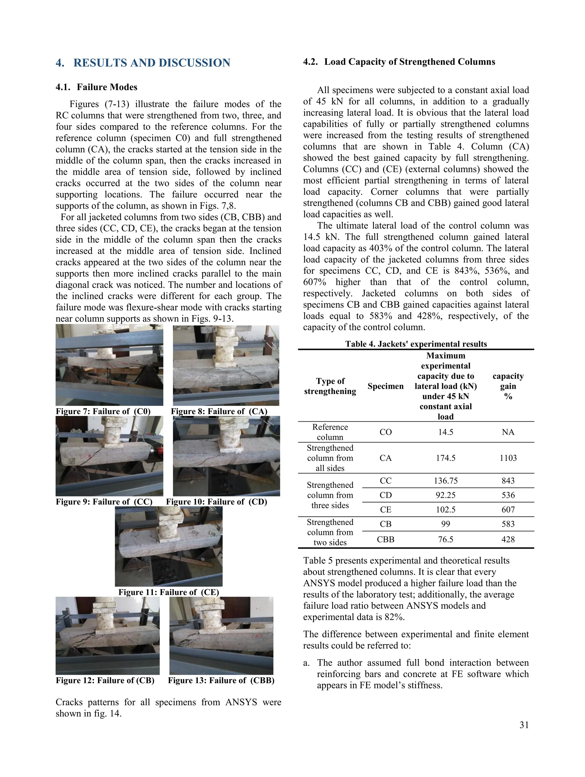
Figures (7-13) illustrate the failure modes of the
RC columns that were strengthened from two, three, and
four sides compared to the reference columns. For the
reference column (specimen C0) and full strengthened
column (CA), the cracks started at the tension side in the
middle of the column span, then the cracks increased in
the middle area of tension side, followed by inclined
cracks occurred at the two sides of the column near
supporting locations. The failure occurred near the
supports of the column, as shown in Figs. 7,8.
For all jacketed columns from two sides (CB, CBB) and
three sides (CC, CD, CE), the cracks began at the tension
side in the middle of the column span then the cracks
increased at the middle area of tension side. Inclined
cracks appeared at the two sides of the column near the
supports then more inclined cracks parallel to the main
diagonal crack was noticed. The number and locations of
the inclined cracks were different for each group. The
failure mode was flexure-shear mode with cracks starting
near column supports as shown in Figs. 9-13.
Figure 7: Failure of (C0) Figure 8: Failure of (CA)
Figure 9: Failure of (CC) Figure 10: Failure of (CD)
Figure 11: Failure of (CE)
Figure 12: Failure of (CB) Figure 13: Failure of (CBB)
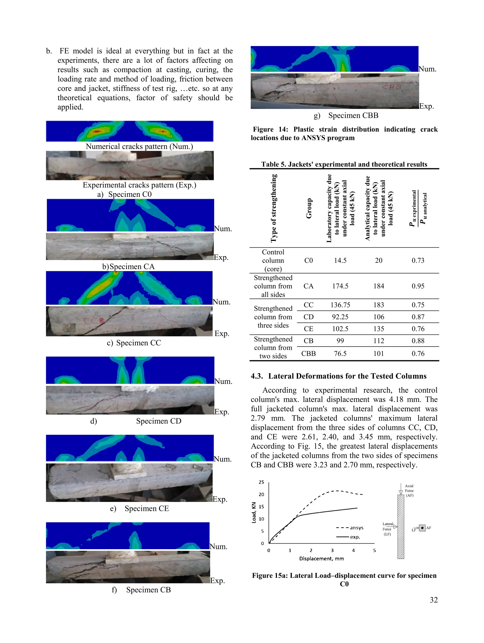
Cracks patterns for all specimens from ANSYS were
shown in fig. 14.
4.2. Load Capacity of Strengthened Columns
All specimens were subjected to a constant axial load
of 45 kN for all columns, in addition to a gradually
increasing lateral load. It is obvious that the lateral load
capabilities of fully or partially strengthened columns
were increased from the testing results of strengthened
columns that are shown in Table 4. Column (CA)
showed the best gained capacity by full strengthening.
Columns (CC) and (CE) (external columns) showed the
most efficient partial strengthening in terms of lateral
load capacity. Corner columns that were partially
strengthened (columns CB and CBB) gained good lateral
load capacities as well.
The ultimate lateral load of the control column was
14.5 kN. The full strengthened column gained lateral
load capacity as 403% of the control column. The lateral
load capacity of the jacketed columns from three sides
for specimens CC, CD, and CE is 843%, 536%, and
607% higher than that of the control column,
respectively. Jacketed columns on both sides of
specimens CB and CBB gained capacities against lateral
loads equal to 583% and 428%, respectively, of the
capacity of the control column.
Table 4. Jackets' experimental results
Type of
strengthening
Specimen
Maximum
experimental
capacity due to
lateral load (kN)
under 45 kN
constant axial
load
capacity
gain
%
Reference
column
CO 14.5 NA
Strengthened
column from
all sides
CA 174.5 1103
Strengthened
column from
three sides
CC 136.75 843
CD 92.25 536
CE 102.5 607
Strengthened
column from
two sides
CB 99 583
CBB 76.5 428
Table 5 presents experimental and theoretical results
about strengthened columns. It is clear that every
ANSYS model produced a higher failure load than the
results of the laboratory test; additionally, the average
failure load ratio between ANSYS models and
experimental data is 82%.
The difference between experimental and finite element
results could be referred to:
a. The author assumed full bond interaction between
reinforcing bars and concrete at FE software which
appears in FE model’s stiffness.
6.
32
b. FE modelis ideal at everything but in fact at the
experiments, there are a lot of factors affecting on
results such as compaction at casting, curing, the
loading rate and method of loading, friction between
core and jacket, stiffness of test rig, …etc. so at any
theoretical equations, factor of safety should be
applied.
Numerical cracks pattern (Num.)
Experimental cracks pattern (Exp.)
a) Specimen C0
Num.
Exp.
b)Specimen CA
Num.
Exp.
c) Specimen CC
Num.
Exp.
d) Specimen CD
Num.
Exp.
e) Specimen CE
Num.
Exp.
f) Specimen CB
Num.
Exp.
g) Specimen CBB
Figure 14: Plastic strain distribution indicating crack
locations due to ANSYS program
Table 5. Jackets' experimental and theoretical results
Type
of
strengthening
Group
Laboratory
capacity
due
to
lateral
load
(kN)
under
constant
axial
load
(45
kN)
Analytical
capacity
due
to
lateral
load
(kN)
under
constant
axial
load
(45
kN)
Control
column
(core)
C0 14.5 20 0.73
Strengthened
column from
all sides
CA 174.5 184 0.95
Strengthened
column from
three sides
CC 136.75 183 0.75
CD 92.25 106 0.87
CE 102.5 135 0.76
Strengthened
column from
two sides
CB 99 112 0.88
CBB 76.5 101 0.76
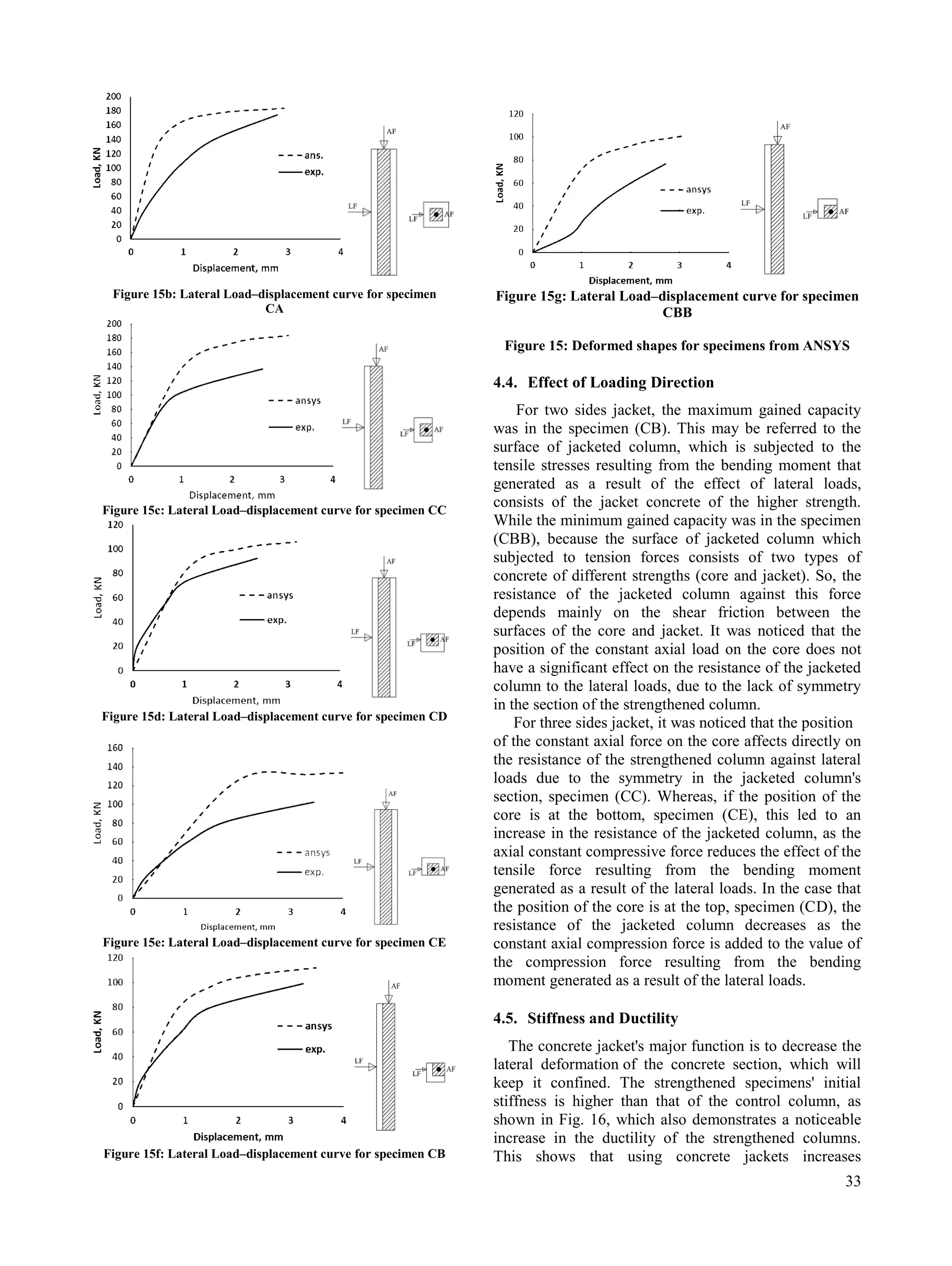
4.3. Lateral Deformations for the Tested Columns
According to experimental research, the control
column's max. lateral displacement was 4.18 mm. The
full jacketed column's max. lateral displacement was
2.79 mm. The jacketed columns' maximum lateral
displacement from the three sides of columns CC, CD,
and CE were 2.61, 2.40, and 3.45 mm, respectively.
According to Fig. 15, the greatest lateral displacements
of the jacketed columns from the two sides of specimens
CB and CBB were 3.23 and 2.70 mm, respectively.
Figure 15a: Lateral Load–displacement curve for specimen
C0
7.
33
Figure 15b: LateralLoad–displacement curve for specimen
CA
Figure 15c: Lateral Load–displacement curve for specimen CC
Figure 15d: Lateral Load–displacement curve for specimen CD
Figure 15e: Lateral Load–displacement curve for specimen CE
Figure 15f: Lateral Load–displacement curve for specimen CB
Figure 15g: Lateral Load–displacement curve for specimen
CBB
Figure 15: Deformed shapes for specimens from ANSYS
4.4. Effect of Loading Direction
For two sides jacket, the maximum gained capacity
was in the specimen (CB). This may be referred to the
surface of jacketed column, which is subjected to the
tensile stresses resulting from the bending moment that
generated as a result of the effect of lateral loads,
consists of the jacket concrete of the higher strength.
While the minimum gained capacity was in the specimen
(CBB), because the surface of jacketed column which
subjected to tension forces consists of two types of
concrete of different strengths (core and jacket). So, the
resistance of the jacketed column against this force
depends mainly on the shear friction between the
surfaces of the core and jacket. It was noticed that the
position of the constant axial load on the core does not
have a significant effect on the resistance of the jacketed
column to the lateral loads, due to the lack of symmetry
in the section of the strengthened column.
For three sides jacket, it was noticed that the position
of the constant axial force on the core affects directly on
the resistance of the strengthened column against lateral
loads due to the symmetry in the jacketed column's
section, specimen (CC). Whereas, if the position of the
core is at the bottom, specimen (CE), this led to an
increase in the resistance of the jacketed column, as the
axial constant compressive force reduces the effect of the
tensile force resulting from the bending moment
generated as a result of the lateral loads. In the case that
the position of the core is at the top, specimen (CD), the
resistance of the jacketed column decreases as the
constant axial compression force is added to the value of
the compression force resulting from the bending
moment generated as a result of the lateral loads.
4.5. Stiffness and Ductility
The concrete jacket's major function is to decrease the
lateral deformation of the concrete section, which will
keep it confined. The strengthened specimens' initial
stiffness is higher than that of the control column, as
shown in Fig. 16, which also demonstrates a noticeable
increase in the ductility of the strengthened columns.
This shows that using concrete jackets increases
8.
34
ductility. In general,larger shortenings than those of the
reference columns were achieved by all the strengthened
columns.
Figure 16: Lateral Load – displacement curves
5. CONCLUSIONS
Reinforced concrete columns strengthened using
concrete jackets were experimentally studied in the
conducted research. The columns were subjected to both
axial and lateral loads. Based on the experimental and
theoretical investigations conducted in this research, the
following could be concluded:
Increasing number of strengthening sides increases
column gained capacity for columns subjected to
both axial and lateral loadings. It was noticed that
the gained capacity depends on loading direction
with respect to jacket location.
The lateral load capacity of columns strengthened
from two sides increased by 583 % and 428% when
column core being in compression and tension side,
respectively. When the column core is located in
tension side of bending moment, the lateral load
capacity of strengthened column is less than
columns with core in compression side.
In the case of three sides jacket: columns with
concrete jackets located in compression and tension
fibers have the largest gained lateral capacity of
843% from control specimen. When column core is
located in compression or tension fibers of the
strengthened column, the gained lateral capacity was
536% and 607%, respectively. It could be concluded
from this point, when the strengthening jacket can
serve as an independent section from the column
core against the compression and tension forces of
lateral load's bending moment the column lateral
capacity is increased.
The results of the finite element models agree with
an acceptable margin to the experimental results and
it achieved an accuracy of 82 %.
6. REFERENCES
[1] A Zaiter, Review on Strengthening Reinforced Concrete
Columns Using Reinforced Concrete Jackets, IOP
Conference Series: Earth and Environmental Science vol
614 (2020).
[2] Khaled Mohamed Mahmoud, Hassan Mohamed Hassan
Ibrahim, Kamal Gad Sharobem. Experimental
Investigation of strengthened short concrete columns. Port
said engineering research journal (PSERJ) 18 (2) (2014)
99-108.
[3] H. Rodrigues, P. M. Pradhan, A. Furtado, P. Rocha,
N. Vila-Pouca, Structural Repair and Strengthening of RC
Elements with Concrete Jacketing, Strengthening and
Retrofitting of Existing Structures 9 (2018) 181-198.
[4] Ahmed Mohamed Sayed, Mohamed Mohamed Rashwan,
Mohamed Emad Helmy, Experimental Behavior of
Cracked Reinforced Concrete Columns Strengthened with
Reinforced Concrete Jacketing, Materials 2020, 13(12),
2832; doi.org/10.3390/ma13122832
[5] Arafa et al, Repairing and Strengthening of Damaged RC
Columns using thin concrete Jacketing, Advances in Civil
Engineering (2019) 1-17.
https://doi.org/10.455/2019/2987412
[6] K. N. Bakhsh, Evaluation of bond strength between
overlay and substrate in concrete repairs, Master Degree
thesis, Royal Institute of Technology (KTH), Stockholm,
Sweden, 2010.
[7] A. Irene Ortega et al., Study on RC columns repaired on
all four sides with cementitious mortars, Construction and
Building Materials 161 (2018) 53-62.
[8] Pavlo KRAINSKYI, Zinoviy BLIKHARSKIY, Roman
KHMIL, Experimental investigation of reinforced
concrete columns strengthened by jacketing, Journal of
Multidisciplinary Engineering Science and Technology 2
(2015) 1959–1963.
[9] Eduardo N.B.S. Júlio, Fernando A.B. Branco, and Vítor
D. Silva, "Reinforced concrete jacketing - Interface
influence on cyclic loading response", ACI Structural
Journal, Vol. 105, 2008, pp. 471-477.
[10] Stephanos E. Dritsos, " Seismic strengthening of columns
by adding new concrete", Bulletin of the New Zealand
Society for Earthquake Engineering, Vol. 40, 2007, pp.
49-68.
[11] Ali Zaiter, Tze Liang Lau, " Experimental study of jacket
height and reinforcement effects on seismic retrofitting of
concrete columns", Vol. 31, 2021, pp. 1084-1095.
[12] Thermou, G. E., Papanikolaou, V.K. & Kappos, A. J.,
"Flexural behaviour of reinforced concrete jacketed
columns under reversed cyclic loading", Engineering
Structures, Vol. 76, 2014, pp. 270-282.
[13] Khaled Mohamed Mahmoud, Ezzat A. Sallam, Hassan M.
H. Ibrahim, "Behavior of partially strengthened reinforced
concrete columns from two or three sides of the
perimeter", Case studies in construction materials, Vol.
17, 2022, doi.org/10.1016/j.cscm. 2022.e0480.
[14] American Society for Testing and Materials (ASTM)
number C31, Making and Curing Concrete Test
Specimens.
![27
Experimental and Theoretical Behaviors of Edge and Corner Jacketed R.C.
Columns Subjected to Combined Axial and Lateral Loads
Hassan M. H. Ibrahim 1
, Khaled Mohamed Mahmoud 2, *
, Ezzaat A. Sallam 3
1
Civil Department, Faculty of Engineering, Port Said University, Port said, Egypt., email: hi_hgh@yahoo.com
2
PhD. (candidate), Projects manager at Suez Canal Authority, Port Said, Egypt, email: khaled.mahmoud@eng.psu.edu.eg
3
Civil Department, Faculty of Engineering, Port Said University, Port said, Egypt. email: ezzat.sallam@eng.psu.edu.eg
*Corresponding author, Email address khaled.mahmoud@eng.psu.edu.eg, DOI: 10.21608/pserj.2023.186945.1214,
Received 19-1-2023,
Revised 23-2-2023,
Accepted 23-2-2023
© 2023 by Author(s) and PSERJ.
This is an open access article
licensed under the terms of the
Creative Commons Attribution
International License (CC BY
4.0).
http://creativecommons.org/licen
ses/by/4.0/
ABSTRACT
In this paper an experimental and numerical investigations were performed to study the
performance of partially jacketed R.C. columns subjected to both axial and lateral loads.
The current research also investigates the effect of the lateral load direction, with respect
to jacket's direction during constant axial load, on the structural response of strengthened
columns. The experimental study consists of seven square columns of 100 x 100 mm2
cross-section dimensions and total length of 1000 mm. The columns were strengthened
from different sides with 50 mm concrete jackets. The strengthened columns were tested
under constant axial load with an increasing lateral force up to column failure. Columns
capacities and modes of failure were illustrated and discussed. Going deep into the
investigation, a finite element analysis was performed on the experimented columns. A
satisfactory agreement was found when the experimental and numerical data were
compared together. The ultimate lateral loads of the strengthened columns from two, three,
and four sides increased up to 5.83, 8.43, and 11.03 times the lateral load capacity of
control columns, respectively. The study also concluded that the loading direction has a
significant effect on column lateral capacity.
Keywords: Lateral loads, Concrete jacket, RC columns, Strengthening, Partial
strengthening.
1. INTRODUCTION
Strengthening of edge or corner columns from all sides
of the perimeter may be not applicable due to
neighboring buildings or to reserve the building's facade
from distortion. Therefore, partial strengthening from
two or three sides could be used. A group of research
work have been carried out to investigate the efficiency
of full jacket strengthening under the effect of combined
loads [1]. K. M. Mahmoud et al. [2] studied
experimentally and theoretically the concrete jacketing,
the steel cage and the factors affecting steel cage column
capacity. From their results, some modifications were
implemented on jackets to improve the efficiency of
them. H. Rodrigues et al. [3] wrote a book contains case
studies of full strengthening columns and explains the
various methods of repairing and strengthening. Ahmed
et al. [4] studied the effectiveness of jacketed RC
columns after cracking investigated at the models'
accuracy while considering the influence of the column's
size, the quantity of reinforcement, and cracked and
uncracked columns. In order for the strengthened
columns to reach the safety limit, they concluded that a
reduction coefficient with values of 94% and 76% for the
strengthened columns before and after cracking,
respectively, must be used. Additionally, compared to
strengthening before crack, strengthening after cracking
decreases the column's ultimate load capacity by 15.7%,
14.1%, and 13.5% for square, rectangular, and circular
columns, respectively. Arafa et al. [5] illustrated the
performance of restoration of deteriorated reinforced
concrete columns using thin concrete jacketing by
increasing the contact between the interfaces of the core
and jacket and found that using shear studs were the
most effective among all used techniques. While,
Bakhsh, Ortega, Krainskyi, and et al. [6-8] found that the
behavior of repaired columns is unaffected by
using bonding agents. Eduardo et al. [9] found that using
sandblasting is the best surface treatment between the
PORT SAID ENGINEERING RESEARCH JOURNAL
Faculty of Engineering - Port Said University
Volume 27 No. 1 pp: 27-34](https://image.slidesharecdn.com/experimentalandtheoreticalbehaviorsofedgeandcornerjacketedr-250601112808-f9cf5733/75/Experimental-and-Theoretical-Behaviors-of-Edge-and-Corner-Jacketed-R-C-Columns-Subjected-to-combined-axial-and-lateral-loads-pdf-1-2048.jpg)
![28
core and jacket. Dritsos [10] illustrated that the resistance
capacity factor, Kr, rises with increasing interface
roughness, falling axial load, and rising cross-sectional
area ratio of the original concrete to the jacket. It is
obvious that using steel connectors at the interface is
necessary when adding more concrete layers due to the
benefits of the bend down bars. Zaiter and Tze [11]
studied the partially strengthening of columns according
to jacket's height and found that the column's stiffness
was enhanced by increasing the jacket height and
strengthening, and Over the jacket, a short column shear
failure was caused by the stiffness irregularity. Thermou
et al. [12] studied of the behavior of jacketed structural
elements. Reinforced concrete jacketing was conducted
to analyze the behavior under reversed cyclic stress. To
evaluate the bending response to cyclic loading, a
computing approach that takes slip at the interfaces into
consideration is also developed. Previous studies
disregard the strengthening of edge and corner columns
and instead place more emphasis on strengthened
columns by full jacket. The authors have previously
investigated the performance of RC columns
strengthened by RC jackets from two, three, and four
sides of the perimeter subjected to axial loads [13]. The
study examined the effects of using various column and
strengthening jacket interactions, including friction,
dowels, and welding. According to the study, welding
jacket stirrups to the existing column's stirrups is the
most effective stirrup arrangement for partially jacketed
columns.
There are a few research efforts on partially jacketed,
either corner and edge, columns subjected to both axial
and lateral loads. Moreover, it was noticed that there is a
research gap should be filled in studying the effect of
lateral load direction on the structural efficiency of the
jacketed concrete columns.
2. EXPERIMENTAL WORK
2.1. Specimens Configurations
The experimental program consists of seven case
studies: The first case is the reference column before
strengthening, second case is full strengthened reinforced
concrete column, cases 3-5 are strengthened reinforced
concrete columns by concrete jackets from three sides,
cases 6 and 7 are strengthened reinforced concrete
columns by concrete jackets from two sides. Details of
specimens are indicated in Fig. 1. Tables 1 and 2
describe the studied cases.
Table 1. Control column parameters
Column
Column
dimensions
Main
reinforcement
Stirrups Remark
C0 100x100 mm 4Ø10 9Ø4
Control
column
Table 2. Jacketed columns parameters
Specimen
No.
Strengthen
ed
column
dimensions
(mm)
Jacket
main
reinfor-
cement
Jacket
stirrups
Remark.
CA 200x200
4Ø10
9Ø6
Full
jacketed
column
CC
200x150
Jacketed
columns
from three
sides
CD
CE
CB
150x150 3Ø10
Jacketed
columns
from two
sides
CBB
(a) Control
column
elevation
(b) Strengthened columns elevations
Co CA CC, CD, CE CB, CBB
Figure 1: Specimens details; a) Control column
b) Strengthened columns
2.2. Materials Properties
Concrete with strength 14 MPa was cast for control
columns and 26 MPa for jackets. Concrete was cast
using materials from the local market. Specimen
preparation was done in a manner that was similar to that
should be followed in the site. For control columns, OPC](https://image.slidesharecdn.com/experimentalandtheoreticalbehaviorsofedgeandcornerjacketedr-250601112808-f9cf5733/75/Experimental-and-Theoretical-Behaviors-of-Edge-and-Corner-Jacketed-R-C-Columns-Subjected-to-combined-axial-and-lateral-loads-pdf-2-2048.jpg)
![29
type 1 cement with a grade of 42.5 is used; for jackets,
OPC type 1 cement with a grade of 52.5 is used.
Crushed dolomite is utilized as the coarse aggregate,
while sand is used as the fine aggregate. In the mixing
and curing process, potable water was used. High grade
steel with an ultimate strength of 550 MPa and yield
strength of 445 MPa was used for main longitudinal
reinforcement for both the core and the jackets. Mild
steel with ultimate and yield strength 390, 280 MPa,
respectively, is used in the stirrups of the column and
Mild steel with ultimate and yield strength 410, 320 MPa
respectively is used in the jacket. Standard specifications
were applied to test the materials' properties according to
ASTM D638.
2.3. Specimens Preparation
A rotating mixer was used to mix the concrete
components, then Concrete was poured into the
formwork in a vertical direction and vibrated on the
inside and outside. Cubes 150x150x150 mm were also
cast to determine the compressive strength of the
concrete. After pouring and according to ASTM number
C31, the formwork was removed after two days and the
specimens were cured in water for a week [14].
2.4. Strengthening Procedures of RC Jacket
28 days after casting, the specimens were ready for
strengthening. The control column (C0) before
strengthening as well as specimens (CA, CB, CBB, CC,
CD, CE) of strengthened RC columns by using the
concrete jackets from various directions were included in
the research work. The surfaces of control columns were
prepared by grinding. On the surfaces of the control
column, there were loose crusts that were removed with
a wire brush. To place the dowels, holes had to be drilled
through the specimens' prepared surfaces. Dowel grout
was used to fix the dowels. Due to the specifics of each
specimen, the longitudinal reinforced steel and stirrups
of the concrete jacket were inserted into the formwork
and attached to the original column (core). Before
putting the new concrete, the core's concrete surfaces
were moist. To increase the cohesiveness of the old and
new concrete, an epoxy-based bonding agent "kemapoxy
104 with bond strength 114kg/cm2 (ASTM C882) " was
applied to the contact surfaces of the core and jacket. A
vertical pour of concrete was prepared in the formwork,
and it was then compacted. Additionally, 150x150x150
mm cubes were created to evaluate the concrete jacket's
compressive strength. After the pour, the formwork was
removed after two days, and the specimens were water-
cured for a further week.
2.5. Instrumentation and Testing Procedure
The main objective of the test is to investigate the
response of the strengthened columns subjected to both
axial and bending moment. The bending moment could
be generated either by frame action at column top or by
applying lateral force considering column as a beam.
Before testing, all specimens were instrumented as shown
in Fig. 2. A load frame was used to apply lateral load on
specimens and special preparation, to apply constant axial
load on specimen, consisted from hydraulic piston and
load cell to allow axial forces measurement. The columns
were placed and adjusted between the heads of the
loading machine as shown in Fig. 2. Columns were
subjected to constant axial load and a gradually
increasing lateral loads. The axial load value was chosen
to represent service load of reference column before
strengthening. The lateral displacements were measured
using LDVT equipment. When the load reached a small
amount of the maximum load measurement, tests were
stopped.
Figure 2: Loads frame and the system of loading
2.6. Loading Direction
All specimens subjected to axial load as a compression
constant load. At the same time, specimens were
subjected to lateral from various sides. Some specimens
subjected to lateral load at the core column’s side, some
specimens subjected to lateral load at the jacket’s side.
These cases were investigated to simulate various
loading conditions as shown in Fig. 3.
Figure 3: Load direction of each column specimen](https://image.slidesharecdn.com/experimentalandtheoreticalbehaviorsofedgeandcornerjacketedr-250601112808-f9cf5733/75/Experimental-and-Theoretical-Behaviors-of-Edge-and-Corner-Jacketed-R-C-Columns-Subjected-to-combined-axial-and-lateral-loads-pdf-3-2048.jpg)
![30
3. THEORETICAL FORMULATION
In the current work, 3D finite element model was
created using the finite element software ANSYS to
model the geometric and material nonlinear behavior of
control, fully jacketed, and partially jacketed columns.
Fig. 4 presents 3D finite element models of the examined
columns.
C0
CA
CB
CBB
CC
CD
CE
Figure 4: Models of columns specimens
3.1. Element Modeling
The solid element (SOLID65) is used to model
concrete, the element has capability of cracking and
crushing. Drager and Bruker failure criteria was used for
concrete, the tensile and compressive strengths was used
as inputs for this failure criteria. The reinforcement was
modeled using beam element (BEAM188), this element
is accepting bilinear material model as shown in Figure
(6), full bond is assumed between steel and concrete, this
is achieved by maintaining same nodes for concrete and
reinforcement. The interface between core column and
jacked is modeled using three springs in x, y and z
directions using spring element (COMBIN39). The
nonlinear spring element can be provided with nonlinear
force-displacement relationship to simulate interface slip
between the adjacent surfaces. Due to the uncertainty for
the bond strength characteristics between column core
and concrete jacket, the authors provided the interface
spring elements with large stiffness and capacity to
simulate in somehow minimal slipping and separation
between the interface surfaces which is similar to full
bond assumption.
3.2. Material modeling
The cores' and the jackets' concrete strengths were 14
and 26 MPa respectively. The multi-linear stress-strain
curve shown in Fig. 5 was determined using the
following equations to produce the compressive uniaxial
stress-strain relationship for the concrete model:
]
)
/
(
1
/[
* 2
c
c
E
f
(1)
c
c
c E
f /
(2)
(3)
Where
f stress at strain
strain at stress f
c
strain at the ultimate compressive strength c
f
c
E concrete's modulus of elasticity
Figure 5: Concrete stress-strain curve
a) without softening branches in tension and compression
b) with softening branches in tension and compression
The concrete uniaxial tensile strength was 2.6 MPa in
the finite element analysis. Because reinforcing bars are
often long and slender, they are only capable of
transmitting axial forces. Finite element models idealize
the steel uniaxial stress-strain relationship as a bilinear
curve to illustrate elastic-plastic behavior with strain
hardening. It is thought that this relationship holds true
for both compression and tension. The optimum stress-
strain relationships for steel are shown in Figure 6.
Figure 6: Stress against strain model for steel](https://image.slidesharecdn.com/experimentalandtheoreticalbehaviorsofedgeandcornerjacketedr-250601112808-f9cf5733/75/Experimental-and-Theoretical-Behaviors-of-Edge-and-Corner-Jacketed-R-C-Columns-Subjected-to-combined-axial-and-lateral-loads-pdf-4-2048.jpg)
![34
ductility. In general, larger shortenings than those of the
reference columns were achieved by all the strengthened
columns.
Figure 16: Lateral Load – displacement curves
5. CONCLUSIONS
Reinforced concrete columns strengthened using
concrete jackets were experimentally studied in the
conducted research. The columns were subjected to both
axial and lateral loads. Based on the experimental and
theoretical investigations conducted in this research, the
following could be concluded:
Increasing number of strengthening sides increases
column gained capacity for columns subjected to
both axial and lateral loadings. It was noticed that
the gained capacity depends on loading direction
with respect to jacket location.
The lateral load capacity of columns strengthened
from two sides increased by 583 % and 428% when
column core being in compression and tension side,
respectively. When the column core is located in
tension side of bending moment, the lateral load
capacity of strengthened column is less than
columns with core in compression side.
In the case of three sides jacket: columns with
concrete jackets located in compression and tension
fibers have the largest gained lateral capacity of
843% from control specimen. When column core is
located in compression or tension fibers of the
strengthened column, the gained lateral capacity was
536% and 607%, respectively. It could be concluded
from this point, when the strengthening jacket can
serve as an independent section from the column
core against the compression and tension forces of
lateral load's bending moment the column lateral
capacity is increased.
The results of the finite element models agree with
an acceptable margin to the experimental results and
it achieved an accuracy of 82 %.
6. REFERENCES
[1] A Zaiter, Review on Strengthening Reinforced Concrete
Columns Using Reinforced Concrete Jackets, IOP
Conference Series: Earth and Environmental Science vol
614 (2020).
[2] Khaled Mohamed Mahmoud, Hassan Mohamed Hassan
Ibrahim, Kamal Gad Sharobem. Experimental
Investigation of strengthened short concrete columns. Port
said engineering research journal (PSERJ) 18 (2) (2014)
99-108.
[3] H. Rodrigues, P. M. Pradhan, A. Furtado, P. Rocha,
N. Vila-Pouca, Structural Repair and Strengthening of RC
Elements with Concrete Jacketing, Strengthening and
Retrofitting of Existing Structures 9 (2018) 181-198.
[4] Ahmed Mohamed Sayed, Mohamed Mohamed Rashwan,
Mohamed Emad Helmy, Experimental Behavior of
Cracked Reinforced Concrete Columns Strengthened with
Reinforced Concrete Jacketing, Materials 2020, 13(12),
2832; doi.org/10.3390/ma13122832
[5] Arafa et al, Repairing and Strengthening of Damaged RC
Columns using thin concrete Jacketing, Advances in Civil
Engineering (2019) 1-17.
https://doi.org/10.455/2019/2987412
[6] K. N. Bakhsh, Evaluation of bond strength between
overlay and substrate in concrete repairs, Master Degree
thesis, Royal Institute of Technology (KTH), Stockholm,
Sweden, 2010.
[7] A. Irene Ortega et al., Study on RC columns repaired on
all four sides with cementitious mortars, Construction and
Building Materials 161 (2018) 53-62.
[8] Pavlo KRAINSKYI, Zinoviy BLIKHARSKIY, Roman
KHMIL, Experimental investigation of reinforced
concrete columns strengthened by jacketing, Journal of
Multidisciplinary Engineering Science and Technology 2
(2015) 1959–1963.
[9] Eduardo N.B.S. Júlio, Fernando A.B. Branco, and Vítor
D. Silva, "Reinforced concrete jacketing - Interface
influence on cyclic loading response", ACI Structural
Journal, Vol. 105, 2008, pp. 471-477.
[10] Stephanos E. Dritsos, " Seismic strengthening of columns
by adding new concrete", Bulletin of the New Zealand
Society for Earthquake Engineering, Vol. 40, 2007, pp.
49-68.
[11] Ali Zaiter, Tze Liang Lau, " Experimental study of jacket
height and reinforcement effects on seismic retrofitting of
concrete columns", Vol. 31, 2021, pp. 1084-1095.
[12] Thermou, G. E., Papanikolaou, V.K. & Kappos, A. J.,
"Flexural behaviour of reinforced concrete jacketed
columns under reversed cyclic loading", Engineering
Structures, Vol. 76, 2014, pp. 270-282.
[13] Khaled Mohamed Mahmoud, Ezzat A. Sallam, Hassan M.
H. Ibrahim, "Behavior of partially strengthened reinforced
concrete columns from two or three sides of the
perimeter", Case studies in construction materials, Vol.
17, 2022, doi.org/10.1016/j.cscm. 2022.e0480.
[14] American Society for Testing and Materials (ASTM)
number C31, Making and Curing Concrete Test
Specimens.](https://image.slidesharecdn.com/experimentalandtheoreticalbehaviorsofedgeandcornerjacketedr-250601112808-f9cf5733/75/Experimental-and-Theoretical-Behaviors-of-Edge-and-Corner-Jacketed-R-C-Columns-Subjected-to-combined-axial-and-lateral-loads-pdf-8-2048.jpg)