The document details an experiment on bandpass coherent single-bit modulation techniques, specifically Binary ASK (BASK), Binary FSK (BFSK), and Binary PSK (BPSK), using MATLAB. It includes simulations of message signals, modulated and demodulated signals, and corresponding MATLAB code for each technique. Results and inferences are provided, indicating how the amplitude, frequency, and phase of signals change based on logic levels during modulation.

![Bandpass Coherent Single-Bit Modulation Techniques
Aim
To simulate Binary ASK, Binary FSK and Binary PSK using
MATLAB
Algorithm
BASK:
• Representation of message signal:
b = [1 0 1 0]
• Representation of Carrier signal:
x(t) = Asin2πft
• Representation of modulated signal using for
and if loop.
• Representation of Demodulated signal.
• Reconstruction of binary sequence.](https://image.slidesharecdn.com/experiment3dcs-21bec0384-240419163207-5ab51a23/85/Experiment3_DCS-21BEC0384Adityabonnerjee-2-320.jpg)
![Model Graph
BFSK:
• Representation of message signal:
b = [1 0 1 0]
• Representation of Carrier signal:
x(t) = Asin2πt
y(t) = Asin2πt
• Representation of modulated signal using for
and if loop.
• Representation of Demodulated signal.
• Reconstruction of binary sequence.](https://image.slidesharecdn.com/experiment3dcs-21bec0384-240419163207-5ab51a23/85/Experiment3_DCS-21BEC0384Adityabonnerjee-3-320.jpg)
![Model Graph
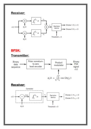
BPSK:
• Representation of message signal
b = [1 0 1 0]
• Representation of Carrier signal
x(t)= Asin2πft
y(t)= -Asin2πft
• Representation of modulated signal using for
and if loop.
• Representation of Demodulated signal.](https://image.slidesharecdn.com/experiment3dcs-21bec0384-240419163207-5ab51a23/85/Experiment3_DCS-21BEC0384Adityabonnerjee-4-320.jpg)
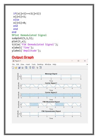
![• Reconstruction of binary sequence.
Model Graph
MATLAB Code
BASK:
clc;
clear all;
close all;
a=1;
f=7;
n=[1 0 1 1 0 0 0];
t=0:0.01:length(n);
t2=0:6;
%Plot Message Signal
subplot(4,1,1);
stairs(t2,n);
title('Message Signal');
xlabel('Time');
ylabel('Amplitude');](https://image.slidesharecdn.com/experiment3dcs-21bec0384-240419163207-5ab51a23/85/Experiment3_DCS-21BEC0384Adityabonnerjee-5-320.jpg)
![xlabel('Time');
ylabel('Amplitude');
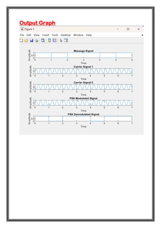
Output Graph
BFSK:
clc;
clear all;
close all;
a=1;
f1=1;
f2=10;
n=[1 0 1 1 0 1 1];
t=0:0.01:length(n);
t2=0:6;
%Plot Message Signal](https://image.slidesharecdn.com/experiment3dcs-21bec0384-240419163207-5ab51a23/85/Experiment3_DCS-21BEC0384Adityabonnerjee-7-320.jpg)
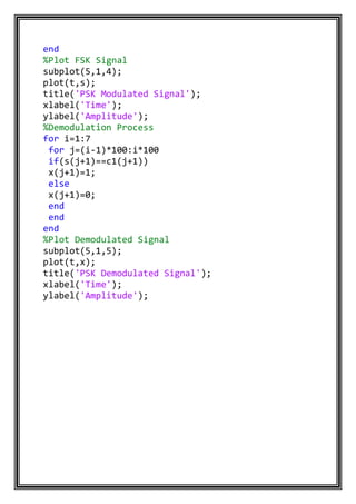
![BPSK:
clc;
clear all;
close all;
a=1;
f=3;
n=[1 0 1 1 0 1 1];
t=0:0.01:length(n);
t2=0:6;
%Plot Message Signal
subplot(5,1,1);
stairs(t2,n);
title('Message Signal');
xlabel('Time');
ylabel('Amplitude');
c1=a*sin(2*pi*f*t);
c2=-a*sin(2*pi*f*t);
%Plot Carrier Signal
subplot(5,1,2);
plot(t,c1);
title('Carrier Signal 1');
xlabel('Time');
ylabel('Amplitude');
subplot(5,1,3);
plot(t,c2);
title('Carrier Signal 2');
xlabel('Time');
ylabel('Amplitude');
%Modulation Process
for i=1:7
for j=(i-1)*100:i*100
if(n(i)==1)
s(j+1)=c1(j+1);
else
s(j+1)=c2(j+1);
end
end](https://image.slidesharecdn.com/experiment3dcs-21bec0384-240419163207-5ab51a23/85/Experiment3_DCS-21BEC0384Adityabonnerjee-10-320.jpg)


![Getting Started with Apache Spark: Big Data Made Simple [Free Meetup]](https://cdn.slidesharecdn.com/ss_thumbnails/apachesparkgettingstarted-260203175547-8361bcc3-thumbnail.jpg?width=640&height=640&fit=bounds)


