SlideShare a Scribd company logo
Efficient • Easy • Effortless
304 Stainless Steel System
Carbon Steel System
316 Stainless Steel System
316 Stainless Steel System Gas
product and
technical manual
The EUROPRESS Pressfitting System is
an extremely fast and simple assembly
system, producing reliable joints with high
mechanical resistance, for civil, industrial
and naval pipework system installations.
Standard diameters range from 15 to 108
mm. Other sizes are available for special
applications.
1.1 MATERIALS
Depending on the application, the following
materials are used:
• stainless steel 316L
• stainless steel 304
• carbon steel
1.2 BENEFITS
The main benefits of the Europress System are:
• fast and easy assembly
• reliable, secure and long-lasting seals
• no fire risk during installation
• high corrosion resistance using 316 Stainless Steel
INTRODUCTION
Europress reserves the right to make improvements. Data may change without prior notice
This manual and its contents are protected by legislation related to
Intellectual Property and as such cannot be reproduced in whole
or in part unless with written authorisation.
PRESS CHECK SLEEVES
Europress are at the forefront of pressing systems with
the innovative Press check sleeve. Rather than wait to fill
an installation with fluid to see if any joint leaks because it
has not been pressed, Europress fittings up to and includ-
ing 54mm have a thin coloured film applied externally on
the O ring seat.
When the joint is pressed the film
is shredded and detaches from the
fitting for easy removal and visual
witness to the completed press
cycle.
Blue sleeves – Stainless steel
Yellow sleeves – Gas fittings
Red sleeves – Carbon steel fittings
This Technical Manual provides basic information as a guide. It
remains the responsibility of the user to ascertain the suitability and
compatibility with their specific application.
2
1 INTRODUCTION 2
1.1 Materials
1.2 Benefits
1.3 INDEX 3
1.4 Features and Benefits 4 - 5
1.4 The Europress Pressfit System 6
2 STAINLESS STEEL EUROPRESS PRESSFITTING
SYSTEM
2.1 Stainless Steel Pipes 7
2.2 Stainless Steel Pressfittings 7
2.3 General Applications 7
2.4 Gas Applications 7
3 EUROPRESS CARBON STEEL SYSTEM
3.1 Pipes and Pressfittings 7
4 STAINLESS STEEL PRESSFITTINGS
4.1 Standard Fittings 8 - 20
4.2 Stainless Steel Super Size Fittings 21 - 22
4.3 S.S. Backing Rings and Flanges 23 - 24
4.5 Gas Fittings 25 - 31
4.6 S.S. Backing Rings and Flanges 32 - 33
5 CARBON STEEL PRESSFITTINGS
5.1 Standard Fittings 34 - 43
5.2 Galvanised Threaded Flanges 44
6 AUXILIARY
6.1 Gaskets 45 - 47
6.2 O Rings 48
6.3 Flat Gaskets 49
6.5 Kova Clips 50 - 54
6.6 Bolted Clips 55
7 TOOLS
7.1 Pressing Tools 56 - 62
7.5 Pipe Tools 63 - 64
8 PIPE LAYING AND EXPANSION
8.1 Expansion 65 - 67
8.4 Pipe Fixing 68 - 69
8.5 Corrosion Resistance 70
8.7 Testing 70
8.8 Noise Insulation 70
8.9 Thermal Insulation 70
9 GUARANTEE 70
10 PROXIMITY TABLES 71 - 72
11 CHEMICAL COMPATIBILITY 73
12 PIPE SIZING 74
13 TROUBLESHOOTING 74
14 FLOW TABLES 75 - 81
15 INSTALLATION INSTRUCTIONS 82 - 83
3
Europress reserves the right to make improvements. Data may change without prior notice
4
features and benefits of the Europress
316L polished S/S tubing for
a superior finish. High alloy
austenitic Cr-Ni-Mo Fittings
made from the same high grade
316 S/S with a choice of O-Rings
for chemical suitability.
The speed of a pressfit system
will amaze you. Competent
tradesmen can install a press fit
system without the need of
qualified welders.
•	Faster and Cheaper
•	Less time on the job
•	Cuts Costs up to 30%
25 Year Manufacturer backed
product guarantee for all
approved applications.
Additionally, pressfit tightness is
guaranteed by the manufacturer
to be in excess of 30 years.
The Europress System is
designed for use with common
"M" profile Press Jaws, the
system is bulk stocked in a
number of locations Australia
wide and is available through
many Plumbing and Industrial
outlets.
Press Fit System
5
Using Press fittings is up to 10
times faster than conventional
Tig welding techniques for
stainless steel. No need to
completely drain pipe contents
prior to alterations. Press
Fittings can be crimped wet
or dry.
Pressing Tool with inbuilt safety
features ensures each press
is the same every time, no
uncertainty of weld integrity.
With the innovative Press Check
Sleeve you don't have to wait
until the system is full of product
to discover leaks! The Press
Check Sleeve, makes it easy to
immediately identify any joints
that have not been pressed.
NO NAKED FLAME
NO HOT WORK PERMITS
NO GAS BOTTLES
No fire hazard or heavy
installation equipment, makes
it easier to comply with OH&S
requirements.
Europress reserves the right to make improvements. Data may change without prior notice
1.4 THE EUROPRESS PRESSFIT SYSTEM
The Europress Press Fit System is the ideal solution for
installing Stainless Steel or Carbon Steel pipework.
Pressfitted pipe joints are fast, easy and risk-free.
Standard Europress Pipe is available in O.D. tube sizes –
15, 22, 28, 35, 42, 54, 76.1, 88.9, & 108
This Technical Manual provides basic information as
a guide. It remains the responsibility of the user to
ascertain the suitability and compatibility with their
specific application.
The pipe is pushed into the fitting, up to the stop, then
the jaw attachments of the pressing tool press the
toroidal end of the fitting into the pipe.
Pressing produces two deformations. The first, radial
deformation, compresses the 0-ring in the toroidal
chamber and guarantees that the pipe is hermetically
sealed. The second, geometric deformation of both
fitting and pipe, creates a mechanical joint, resistant to
slipping and rotation.
The resulting pressing profile varies according to
diameter. Fig 1 shows an assembled joint before
and after pressing. Joints produced in this way are
extremely strong, but flexible enough to withstand the
stresses resulting from initial installation and those,
such as vibrations and thermal expansion etc., that
occurs in normal operating conditions. This is provided
that installation has been carried out according to the
instructions in this manual.
Certifications
The Europress 316L Stainless Steel pipe and standard
fittings have been certified for drinking water use by
many national and international authorities. Notably
it exceeds the demanding quality requirements of the
Australian Watermark and the German Standard DVGW
W534.
2.0 EUROPRESS STAINLESS STEEL
All 316L pipes and pressfittings are made of austenitic
stainless Cr- Ni-Mo steel, n. 1.4404 which conforms to
Standard UNI EN 10088 (AISI 316L ).
304 grade SS pipe n. 1.4307 is available as a more
economic alternative to 316L. The nominal dimension
used to identify both components of the joint refers to
the outside diameter of the pipe.
2.1 PIPES
Pipes for use in mains systems are manufactured to AS
5200.053 and conform to Standard DVGW- GW 547/2004
and are marked as such. Dimensional tolerances
conform to Standard EN ISO 1127 D4/T4. These pipes
are sold in 6-metre lengths and are capped both ends.
Watermark
AS 3688
AS 5200.053
WMKA22265
Activfire
AS 4118.2.1
VdS2344en
VdS2100-26en
Fig. 1 Joining of pressfitting on pipe
Pressfitting O-ring
Pipe
Before pressing
After pressing
Profile view
Outside
diam mm
15 22 28 35 42 54 76.1 88.9 108 139.7 168.3
Thickness 1 1.2 1.2 1.5 1.5 1.5 2 2 2 2 2
6
2.2 STAINLESS STEEL PRESSFITTINGS
Press fittings are manufactured from the same material
as the pipes and conform to AS 3688
The special process used to make the press fittings can
be broken down into the following main stages:
• cutting the pipe into sections and mechanical working
• forming the toroidal seat
• any welding of other parts of the fitting
• heat treatment in a controlled atmosphere at 1050°C to
restore the material’s original characteristics
All process stages conform to Standards UNI EN
ISO 9001 and in compliance with related technical
specifications from DVGW, VdS, etc.
2.3 GENERAL APPLICATIONS
The Europress Stainless Steel system is the ideal
solution for drinking water systems as the AlSI 316L
stainless steel used is completely hygienic and highly
corrosion resistant. The standard o-rings made of black
EPDM, are resistant to aging, heat and chemical
additives and are particularly suitable for all types of
treated water.
The reliable, high-quality components are suitable for
heating, cooling, compressed air, oil and diesel lines
in the civil, industrial and manufacturing sectors.
Conditions of use
• Maximum operating pressure: 16 bar
• Operating temperature: -20°C +95°C
• Maximum temperature: 120°C (On approved applications.)
• Up to 40 Bar/580 psi available on approved applications.
Please refer to technical department.
The Europress Pressfitting System complies with the
CSIRO ACTIVFIRE certification and has been evaluated
and verified as conforming to AS 4118.2.1-1995. It also
has been granted the internationally recognized VdS-
certification for fire extinguisher systems according to
VdS CEA 4001 for both carbon steel and stainless steel
products 22mm-108mm (DN20-DN100).
2.4 GAS APPLICATION
The Europress System meets AS 5200.053 and is
approved in Australia, New Zealand and many European
countries for use in gas distribution systems, with
external above-ground pipes, installed inside or outside
buildings. It can be used for all types of combustible gas,
both natural and liquid. The O-ring gaskets are made
of yellow HNBR, and are compatible with any of the gas
varieties used and are resistant to ageing and heat.
Conditions of use
• Maximum operating pressure: 5 bar
• Operating temperature: -20 °C +70 °C
Certification
The Europress pressfittings comply with AS NZS
5601.1.2013 which requires certification as
conforming to the German Standard DVGW VP614 for
gas applications. To conform to this standard, each of
the welded fittings, complete with o-rings, undergoes a
special helium test. These fittings have a yellow label with
the letters “PN5” or equivalent yellow mark, to indicate
their application.
3. EUROPRESS CARBON STEEL
3.1 Pipes and pressfittings
All pipes and pressfitting are made of carbon steel, 	
E195 or E235 n. 1.0034 which conforms to 			
Standard EN 10305.
The nominal dimension used to identify both
components of the joint refers to the outside diameter of
the pipe.
The following range of diameters and thicknesses
can be used:
		
	
Pipes are sold in 6-metre lengths and dimensional
tolerances must conform to Standard EN I0305.
Pressfitting
The types of pressfittings available are listed in p 34–43
The special process used to make the press fittings can
be broken down into the following main stages:
•cutting the pipe into sections and mechanical
working
•forming the toroidal seat
•any welding of other parts of the fitting
•any annealing heat treatments
•zinc surface treatments
All process stages are subjected to a quality certified
system conforming to Standard UN1 EN ISO 9001/2000.
Marking
All Europress pipes and press fittings are stamped in
accordance with the relevant standard to indicate their
application.
3.2 Various applications
The Europress Pressfit System in carbon steel is
indicated for use in various types of civil and industrial
installations where stainless steel pipework is not
essential.
Typical applications are:
•closed-circuit heating and cooling water systems
•compressed air and inert gas systems
•closed-circuit sprinkler systems
•oil and diesel lines.
All applications should be checked with Europress
Technical department.
The O-ring gaskets, made of black EPDM, are resistant
to ageing, heat and chemical additives and are therefore
particularly suitable for all types of treated water.
Conditions of use
•Maximum operating pressure: 16 bar
•Operating temperature: -20°C +85°C
•Maximum temperature: 120°C (On approved applications.
Please refer to tech. dept.)
Outside
diam mm
15 22 28 35 42 54 76.1 88.9 108
Thickness 1.2 1.2 1.2 1.5 1.5 1.5 2 2 2
7
Europress reserves the right to make improvements. Data may change without prior notice
Part No. d L Z weight gram
SPP0.000015 15 52 10 39
SPP0.000022 22 59 13 62
SPP0.000028 28 61 13 78
SPP0.000035 35 72 18 109
SPP0.000042 42 79 15 147
SPP0.000054 54 90 16 205
SPP0.000076 76.1 142 32 604
SPP0.000089 88.9 163 37 837
SPP0.000108 108 192 38 1,193
Coupling
Part No. d-d1 L H weight gram
SSP0.022015 22-15 60 39 45
SSP0.028015 28-15 72 51 56
SSP0.028022 28-22 67 44 65
SSP0.035015 35-15 82 61 89
SSP0.035022 35-22 83 60 98
SSP0.035028 35-28 73 49 112
SSP0.042015 42-15 91 70 118
SSP0.042022 42-22 87 64 125
SSP0.042028 42-28 98 74 140
SSP0.042035 42-35 79 52 120
SSP0.054015 54-15 110 89 197
SSP0.054022 54-22 107 84 191
SSP0.054028 54-28 99 75 193
SSP0.054035 54-35 128 101 237
SSP0.054042 54-42 97 65 191
SSP0.076042 76,1-42 151 119 425
SSP0.076054 76,1-54 140 103 451
SSP0.089054 88,9-54 156 119 586
SSP0.089076 88,9-76,1 156 101 653
SSP0.108054 108-54 204 167 880
SSP0.108076 108-76,1 196 141 978
SSP0.108089 108-88,9 190 127 992
Reducing Coupling (Spigot x Adaptor) Other Sizes Available	
Stainless steel pipes type 1.4404 (316L) with
Watermarked approval for potable water
Pipe–Austenitic – 6 metre lengths
Part No.
316L
304 ext. Ø
[mm]
thickness
[mm]
length
[m]
weight
[kg/m]
STT0.316015 STT0.304015 15 1 6 0.351
STT0.316022 STT0.304022 22 1.2 6 0.625
STT0.316028 STT0.304028 28 1.2 6 0.805
STT0.316035 STT0.304035 35 1.5 6 1.258
STT0.316042 STT0.304042 42 1.5 6 1.521
STT0.316054 STT0.304054 54 1.5 6 1.972
STT0.316076 STT0.304076 76.1 2 6 3.711
STT0.316089 STT0.304089 88.9 2 6 4.352
STT0.316108 STT0.304108 108 2 6 5.308
4.0 STAINLESS STEEL AISI 316L 4.0
8
Part No. d L Z weight gram Radius
SPP9.000015 15 48 27 57 1.5d
SPP9.000022 22 60 37 97 1.5d
SPP9.000028 28 71 47 143 1.5d
SPP9.000035 35 87 60 198 1.5d
SPP8.000035 35 75 48 173 1.2d
SPP9.000042 42 15 83 314 1.5d
SPP8.000042 42 89 57 261 1.2d
SPP9.000054 54 142 105 499 1.5d
SPP8.000054 54 107 70 391 1.2d
SPP8.000076 76.1 150 95 977 1.2d
SPP8.000089 88.9 174 111 1,325 1.2d
SPP8.000108 108 215 138 2,091 1.2d
Elbow 90°
Part No. d L Z weight gram Radius
SPP4.000015 15 37 16 49 1.5d
SPP4.000022 22 44 21 81 1.5d
SPP4.000028 28 51 27 118 1.5d
SPP4.000035 35 59 32 161 1.5d
SPP2.000035 35 49 22 152 1.2d
SPP4.000042 42 77 45 254 1.5d
SPP2.000042 42 63 31 216 1.2d
SPP4.000054 54 88 51 369 1.5d
SPP2.000054 54 75 38 323 1.2d
SPP2.000076 76.1 98 43 773 1.2d
SPP2.000089 88.9 112 49 991 1.2d
SPP2.000108 108 138 61 1,600 1.2d
Elbow 45°
Part No. d L H Z weight gram Radius
SPS9.000015 15 48 56 27 58 1.5d
SPS9.000022 22 60 68 37 98 1.5d
SPS9.000028 28 71 80 47 147 1.5d
SPS9.000035 35 87 93 60 200 1.5d
SPS8.000035 35 75 83 48 179 1.2d
SPS9.000042 42 115 125 83 331 1.5d
SPS8.000042 42 89 97 57 260 1.2d
SPS9.000054 54 142 149 105 505 1.5d
SPS8.000054 54 107 116 70 400 1.2d
SPS8.000076 76.1 150 165 95 982 1.2d
SPS8.000089 88.9 174 190 111 1,317 1.2d
SPS8.000108 108 215 238 138 2,068 1.2d
Elbow 90° with Spigot End
Part No. d L E weight gram
SPPS.000015 15 71 24 47
SPPS.000022 22 82 27 85
SPPS.000028 28 90 28 114
SPPS.000035 35 99 31 149
SPPS.000042 42 115 35 216
SPPS.000054 54 139 40 316
SPPS.000076 76.1 230 60 874
SPPS.000089 88.9 258 70 1,196
SPPS.000108 108 305 80 1,775
Slip Coupling
9
Europress reserves the right to make improvements. Data may change without prior notice
Part No. d L H Z weight gram Radius
SPS4.000015 15 37 48 16 53 1.5d
SPS4.000022 22 44 53 21 85 1.5d
SPS4.000028 28 51 60 27 117 1.5d
SPS4.000035 35 59 66 32 160 1.5d
SPS2.000035 35 49 51 22 155 1.2d
SPS4.000042 42 77 80 45 237 1.5d
SPS2.000042 42 63 72 31 203 1.2d
SPS4.000054 54 88 97 51 366 1.5d
SPS2.000054 54 75 83 38 310 1.2d
SPS2.000076 76.1 98 117 43 767 1.2d
SPS2.000089 88.9 112 131 49 998 1.2d
SPS2.000108 108 138 154 61 1,510 1.2d
Elbow 45° with Spigot End
Part No. d-Rp L L1 H weight gram
SPF9.015015 15-½ 48 58 27 76
SPF9.022020 22-¾ 60 68 37 123
SPF9.028025 28-1 71 81 47 172
SPF9.035032 35-1¼ 87 95 60 267
Elbow Adaptor 90° with Female Thread
Part No. d-R L L1 H weight gram
SPM9.015015 15-½ 48 58 27 75
SPM9.022020 22-¾ 60 69 37 119
SPM9.028025 28-1 71 81 47 184
SPM9.035032 35-1¼ 87 94 60 262
SPM9.042040 42-1½ 115 116 83 376
SPM9.054050 54-2 142 143 105 667
Elbow Adaptor 90° with Male Thread
Part No. d-R L L1 H weight gram
SPM4.015015 15- ½ 37 38 16 64
SPM4.022020 22- ¾ 44 51 21 102
Elbow Adaptor 45° with Male Thread
4.0 STAINLESS STEEL AISI 316L STANDARD FITTINGS
10
Part No.	 d-G	 L	 L1	 Z	 I 	 I1	 H	 g	 weight
	 [ISO 228]							 	 gram
SPFL.015015 15-½ 46 43 25 12 12 34 5 104
SPFL.022020 22-¾ 52 51 29 16 13 40 6 147
90° Female Elbow with Flush Wall Mount
Part No. d-R L H Z weight gram
SSFA.015015 15 -½ 35 53 23 66
Elbow 90 Spigot with Female Thread
Part No. d-R L H Z Z1 weight gram
SPFA.015015 15-½ 53 36 32 24 121
SPFA.022020 22 - ¾ 57 46 34 33 180
SPFA.028025 28-1 71 54 47 38 329
SPFA.035032 35 - 1¼ 72 62 45 45 455
Elbow Adaptor 90° with Female Thread
Part No. d-R L H Z weight gram
SPMA.015015 15-½ 53 36 32 91
SPMA.015020 15-¾ 62 38 41 137
SPMA.022020 22-¾ 58 40 35 145
SPMA.028025 28-1 63 44 39 245
SPMA.035032 35-1¼ 71 48 44 338
SPMA.042040 42-1½ 81 53 49 425
SPMA.054050 54-2 92 59 55 716
Elbow Adaptor 90° with Male Thread
11
SPFW.015015 15-½ 46 36 65 25 12 148
SPFW.022020 22-¾ 52 2 65 29 13 176
90° Female Elbow with Extended Offset Wall Mount
Part No.	 d-G	 L	 I 	 L1	 z	 I1	 weight
	 [ISO 228]						gram
Europress reserves the right to make improvements. Data may change without prior notice
Part No. d L L1 Z Z1 I weight gram
SPPT.000015 15 74 35 16 14 37 67
SPPT.000022 22 82 40 18 17 41 112
SPPT.000028 28 92 45 22 21 46 149
SPPT.000035 35 102 55 24 28 51 189
SPPT.000042 42 118 61 27 29 59 27
SPPT.000054 54 142 72 34 35 71 382
SPPT.000076 76.1 232 115 61 60 116 1,192
SPPT.000089 88.9 262 127 68 64 131 1,617
SPPT.000108 108 312 155 79 78 156 2,450
Equal Tee
Part No. d-d1-d L L1 Z Z1 I weight gram
SPPT.022015 22-15-22 82 39 18 18 41 98
SPPT.028015 28-15-28 92 42 22 21 46 130
SPPT.028022 28-22-28 92 45 22 22 46 140
SPPT.035015 35-15-35 102 45 24 24 51 164
SPPT.035022 35-22-35 102 46 24 23 51 172
SPPT.035028 35-28-35 102 48 24 24 51 175
SPPT.042015 42-15-42 118 48 27 27 59 213
SPPT.042022 42-22-42 118 51 27 28 59 239
SPPT.042028 42-28-42 118 53 27 29 59 240
SPPT.042035 42-35-42 118 60 27 33 59 242
SPPT.054015 54-15-54 142 56 34 35 71 326
SPPT.054022 54-22-54 142 57 34 34 71 325
SPPT.054028 54-28-54 142 60 34 36 71 348
SPPT.054035 54-35-54 142 66 34 39 71 344
SPPT.054042 54-42-54 142 64 34 32 71 368
SPPT.076022 76.1-22-76.1 232 68 61 45 116 942
SPPT.076028 76.1-28-76.1 232 71 61 47 116 956
SPPT.076035 76.1-35-76.1 232 75 61 48 116 968
SPPT.076042 76.1-42-76.1 232 79 61 47 116 981
SPPT.076054 76.1-54-76.1 232 80 61 43 116 1,067
SPPT.089022 88.9-22-88.9 262 76 68 53 131 1,256
SPPT.089028 88.9-28-88.9 262 76 68 52 131 1,244
SPPT.089035 88.9-35-88.9 262 83 68 56 131 1,267
SPPT.089042 88.9-42-88.9 262 85 68 53 131 1,271
SPPT.089054 88.9-54-88.9 262 93 68 56 131 1,297
SPPT.089076 88.9-76.1-88.9 262 116 68 61 131 1,479
SPPT.108022 108-22-108 312 85 79 62 156 1,919
SPPT.108028 108-28-108 312 88 79 64 156 1,939
SPPT.108032 108-35-108 312 94 79 67 156 1,955
SPPT.108042 108-42-108 312 96 79 64 156 1,886
SPPT.108054 108-54-108 312 102 79 65 156 1,967
SPPT.108076 108-76.1-108 312 125 79 70 156 2,147
SPPT.108089 108-88.9-108 312 135 79 72 156 2,255
Reducing Tee
4.0 STAINLESS STEEL AISI 316L STANDARD FITTINGS
12
Part No. d-Rp L L1 Z Z1 I weight gram
SPFT.015015 15-½-15 74 37 16 25 37 83
SPFT.022015 22-½-22 82 41 18 29 41 117
SPFT.022020 22-¾-22 82 41 18 28 41 131
SPFT.028015 28-½-28 92 44 22 32 46 144
SPFT.028020 28-¾-28 92 45 22 32 46 159
SPFT.028025 28-1-28 92 48 22 32 46 175
SPFT.035015 35-½-35 102 48 24 36 51 178
SPFT.035020 35-¾-35 102 48 24 35 51 189
SPFT.035032 35-1¼-35 102 57 24 40 51 255
SPFT.042015 42-½-42 118 46 27 34 59 240
SPFT.042020 42-¾-42 118 52 27 39 59 254
SPFT.042040 42-1½-42 118 59 27 42 59 384
SPFT.054015 54-½-54 142 55 34 43 71 362
SPFT.054020 54-¾-54 142 58 34 45 71 364
SPFT.054050 54-2-54 142 69 34 47 71 523
SPFT.076020 76.1-¾-76.1 232 68 61 55 116 1,009
SPFT.076050 76.1-2-76.1 232 81 61 59 116 1,194
SPFT.089020 88.9-¾-88.9 262 87 68 74 131 1,210
SPFT.089050 88.9-2-88.9 262 88 68 66 131 1,450
SPFT.108020 108-¾-108 312 86 79 73 156 1,956
SPFT.108050 108-2-108 312 98 79 76 156 2,118
Female Centred Tee
Male Centred Tee
Part No. d L L1 Z Z1 I weight gram
SPMT.015015 15-½ -15 74 38 16 15 37 75
SPMT.022020 22-¾-22 82 43 18 17 41 105
SPMT.028025 28-1-28 92 50 22 21 46 130
SPMT.035032 35-1¼-35 102 56 24 28 51 170
Part No. d-Rp L H weight gram
SSF0.015015 15-½ 136 148 95
SSF0.022015 22-½ 140 152 150
SSF0.022020 22-¾ 139 152 148
SSF0.028025 28-1 94 110 145
SSF0.035032 35-1¼ 93 110 210
SSF0.042040 42-1½ 93 110 300
SSF0.054050 54-2 98 120 408
Adaptor with Female Thread and Spigot End
13
Europress reserves the right to make improvements. Data may change without prior notice
Part No. d-Rp L H weight gram
SPF0.015015 15-½ 53 20 52
SPF0.015020 15-¾ 67 33 81
SPF0.022015 22-½ 52 17 77
SPF0.022020 22-¾ 56 20 75
SPF0.022025 22-1 70 31 105
SPF0.028020 28-¾ 73 36 105
SPF0.028025 28-1 62 22 103
SPF0.028032 28-1¼ 80 39 171
SPF0.035025 35-1 81 38 136
SPF0.035032 35-1¼ 72 28 170
SPF0.035040 35-1½ 83 39 259
SPF0.042032 42-1¼ 94 45 221
SPF0.042040 42-1½ 74 25 252
SPF0.054040 54-1½ 106 52 328
SPF0.054050 54-2 84 25 342
Adaptor with Female Thread
Part No. d-R L H weight gram
SPM0.015010 15-3
/8 50 29 50
SPM0.015015 15-½ 52 31 52
SPM0.015020 15-¾ 64 43 66
SPM0.022015 22-½ 68 45 73
SPM0.022020 22-¾ 58 35 74
SPM0.022025 22-1 72 49 116
SPM0.028020 28-¾ 73 49 100
SPM0.028025 28-1 62 38 115
SPM0.028032 28-1¼ 79 55 166
SPM0.035025 35-1 82 55 148
SPM0.035032 35-1¼ 70 43 165
SPM0.035040 35-1½ 84 57 198
SPM0.042032 42-1¼ 93 61 216
SPM0.042040 42-1½ 75 43 204
SPM0.054040 54-1½ 105 68 271
SPM0.054050 54-2 87 50 368
SPM0.076065 76.1- 2½ 125 70 820
SPM0.089080 88.9- 3 138 75 1,158
Adaptor with Male Thread
Part No. d-R L weight gram
SSM0.015015 15-½ 70 55
SSM0.022020 22-¾ 75 80
SSM0.028025 28-1 75 120
SSM0.035032 35-1¼ 80 170
SSM0.042040 42-1½ 91 220
SSM0.054050 54-2 102 384
Adaptor with Male Thread and Spigot End
4.0 STAINLESS STEEL AISI 316L STANDARD FITTINGS
14
Part No. d-G L L1 Z Z1 H I I1 weight gram
SPFM.015015 15-½ 74 43 21 31 34 12 13 130
Off Centred Tee with Female Thread
Part No. d-G L L1 I I1 Z H weight gram
SPFC.015015 15-½ 56 44 15 12 35 139 166
Lugged Elbow with Female Tap Outlet
Part No. D-RP NUT L Z weight gram
SPFN.015015 15-½ ST. STEEL 73 40 139
SPFN.015020 15-¾ ST. STEEL 75 41 176
SPFN.022020 22-¾ ST. STEEL 76 40 205
SPFN.022025 22-1 ST. STEEL 79 40 235
SPFN.028025 28-1 ST. STEEL 83 43 387
SPFN.035032 35-1¼ ST. STEEL 93 49 448
SPFN.042040 42-1½ ST. STEEL 96 47 542
SPFN.054050 54-2 ST. STEEL 113 54 943
Part No. D-RP NUT L Z weight gram
SPFQ.015015 15-½ BRASS 73 40 145
SPFQ.015020 15-¾ BRASS 75 41 182
SPFQ.022020 22-¾ BRASS 76 40 212
SPFQ.022025 22-1 BRASS 79 40 242
SPFQ.028025 28-1 BRASS 83 43 398
SPFQ.035032 35-1¼ BRASS 93 49 467
SPFQ.042040 42-1½ BRASS 96 47 562
SPFQ.054050 54-2 BRASS 113 54 973
Female Barrel Union Brass / Stainless Steel Nut EPDM Flat Seal
15
Europress reserves the right to make improvements. Data may change without prior notice
Part No. D-RP NUT L H weight gram
SPMN.015015 15 -½ ST. STEEL 76 55 141
SPMN.015020 15 -¾ ST. STEEL 80 59 160
SPMN.022015 22 -½ ST. STEEL 80 57 232
SPMN.022020 22 - ¾ ST. STEEL 82 59 215
SPMN.022025 22-1 ST. STEEL 86 63 249
SPMN.028025 28-1 ST. STEEL 88 64 349
SPMN.035032 35 - 1¼ ST. STEEL 100 73 525
SPMN.042040 42 - 1½ ST. STEEL 106 74 608
SPMN.054050 54 - 2 ST. STEEL 122 85 978
Part No. D-RP NUT L H weight gram
SPMQ.015015 15-½ BRASS 76 55 147
SPMQ.015020 15-¾ BRASS 80 59 166
SPMQ.022015 22-½ BRASS 80 57 239
SPMQ.022020 22-¾ BRASS 82 59 222
SPMQ.022025 22-1 BRASS 86 63 256
SPMQ.028025 28-1 BRASS 88 64 360
SPMQ.035032 35-1¼ BRASS 100 73 544
SPMQ.042040 42-1½ BRASS 106 74 628
SPMQ.054050 54-2 BRASS 122 85 1008
Male Barrel Union Brass / Stainless Steel Nut EPDM Flat Seal
Part No. D-RP NUT L Z weight gram
SPPQ.015015 15 BRASS 97 55 170
SPPQ.022022 22 BRASS 105 59 222
SPPQ.028028 28 BRASS 111 63 345
SPPQ.035035 35 BRASS 124 70 540
SPPQ.042042 42 BRASS 134 70 640
SPPQ.054054 54 BRASS 144 70 970
Part No. D-RP NUT L Z weight gram
SPPN.015015 15 ST. STEEL 97 55 154
SPPN.022022 22 ST. STEEL 105 59 215
SPPN.028028 28 ST. STEEL 111 63 334
SPPN.035035 35 ST. STEEL 124 70 521
SPPN.042042 42 ST. STEEL 134 70 620
SPPN.054054 54 ST. STEEL 144 70 940
Pipe - Pipe Barrel Union Brass / Stainless Steel Nut EPDM Flat
4.0 STAINLESS STEEL AISI 316L STANDARD FITTINGS
16
Part No. d L Z weight gram
SPE0.000015 15 37 16 27
SPE0.000022 22 41 18 44
SPE0.000028 28 46 22 63
SPE0.000035 35 51 24 81
SPE0.000042 42 59 27 119
SPE0.000054 54 72 35 171
SPE0.000076 76.1 95 40 427
SPE0.000089 88.9 107 44 559
SPE0.000108 108 127 50 821
Cap
3 Piece Ball Valve Adaptor Ends
Part No. d L L1 C A M H weight gram
SPPV.00015 15 118 48 22 20 105 57 454
SPPV.00022 22 133 51 31 21 110 67 860
SPPV.00028 28 147.9 55 37.9 24 130 85 1.054
SPPV.00035 35 177 65 47 27 130 85 1.922
SPPV.00042 42 205 74 57 32 160 100 2.584
SPPV.00054 54 228 80 68 38 160 110 3.500
SPPV.00076 76.1 316 115 86 55 235 130 9.180
SPPV.00089 88.9 346 124 98 64 245 140 12.98
SPPV.00108 108 432 153 126 78 330 170 20.24
Part No. d-D L Z weight gram
SPR0.028025 28 x 33.7 87 63 171
SPR0.035032 35 x 42.4 94.5 67.5 239
SPR0.042040 42 x 48.3 105.5 73.5 298
SPR0.054050 54 x 60.3 124 87 429
SPR0.076065 76.1 x 76.1 150 95 986
SPR0.089080 88.9 x 88.9 165.5 102.5 1.229
SPR0.108100 108 x 114.4 184 107 1.393
Roll Groove Adaptor
Imperial Weld Adaptor
Part No. d1 D imp OD
imp/mm
L H weight gram
SPBJ.015015 15 ½ 0.840/21.3 60 39 0.045
SPBJ.022020 22 ¾ 1.050/26.7 67 44 0.065
SPBJ.028025 28 1 1.315/33.4 73 49 0.112
SPBJ.035032 35 1¼ 1.900/42.2 79 52 0.12
SPBJ.042040 42 1½ 1.900/48.3 97 65 0.191
SPBJ.054050 54 2 2.375/60.3 140 103 0.451
SPBJ.076065 76.1 2½ 2.87/73.0 156 101 0.653
SPBJ.076080 76.1 3 3.50/88.9 190 127 0.653
SPBJ.089080 88.9 3 3.50/88.9 190 127 0.992
SPBJ.108100 108 4 4.50/114.3 184 107 1.393
17
Europress reserves the right to make improvements. Data may change without prior notice
Part No. d L D D1 Z C S weight gram
SPJF.015015 15 38 34 14 17 4 10 57
SPJF.022020 22 39 39 21 16 4 9 70
SPJF.028025 28 42 45 27 18 4 9 89
SPJF.035032 35 46 56 32 19 4 9 127
SPJF.042040 42 50 62 39 18 4 9 156
Adaptor Flange (small)
Part No. d L weight gram
SPB0.000015 15 25 17
SPB0.000022 22 27 30
SPB0.000028 28 30 37
SPB0.000035 35 34 51
SPB0.000042 42 38 67
SPB0.000054 54 44 100
SPB0.000076 76 68 290
SPB0.000089 89 78 390
SPB0.000108 108 94 595
Welding Joint
Part No. d Nominal
flange
size
Inch
size
D P L T
SPEF.015015 15 15 1/2” 95 67 30 6
SPEF.022020 22 20 3/4” 102 73 32 6
SPEF.028025 28 25 1” 114 83 36 7
SPEF.035032 35 32 1¼” 121 87 41 8
SPEF.042040 42 40 1½” 133 98 46 9
SPEF.054050 54 50 2” 152 114 50 10
SPEF.076080 76.1 80 3” 185 146 77 11
SPEF.089080 88.9 80 3” 185 146 91 11
SPEF.108100 108 100 4” 215 178 107 13
Adaptor Flange (large) Table E standard DIN  ANSI available
Part No. d D Z L T
SSJF.076080 76.1 106 28 128 3
SSJF.089080 88.9 125 26 149 3
SSJF.108100 108 158 22 175 4
Stub Flange
D P
L
T
d
4.0 STAINLESS STEEL AISI 316L STANDARD FITTINGS
18
Use in conjunction with backing rings on page 23
15° Bend
Part No. d H1 H K K1 weight gram
SSS1.000015 15 122 60 21 83 76
SSS1.000022 22 124 50 7 81 110
SSS1.000028 28 136 45 7 47 146
SSS1.000035 35 234 62 30 110 381
SSS1.000042 42 276 94 41 144 558
SSS1.000054 54 337 117 65 165 869
SSS1.000076 76.1 230 226 65 65 1.607
SSS1.000089 88.9 260 240 80 80 2.109
SSS1.000108 108 291 222 95 95 2.546
30° Bend
Part No. d H1 H K K1 weight gram
SSS3.000015 15 122 60 21 83 76
SSS3.000022 22 124 50 6 80 110
SSS3.000028 28 130 54 7 47 144
SSS3.000035 35 218 80 30 110 382
SSS3.000042 42 274 98 44 144 560
SSS3.000054 54 324 137 65 165 905
SSS3.000076 76.1 200 202 66 66 1.41
SSS3.000089 88.9 262 264 80 80 2.183
SSS3.000108 108 259 272 95 95 2.622
45° Bend
Part No. d H1 H K K1 weight gram
SSS4.000015 15 120 62 19 77 76
SSS4.000022 22 120 56 7 71 111
SSS4.000028 28 122 58 2 66 146
SSS4.000035 35 206 94 20 132 380
SSS4.000042 42 262 114 1 149 576
SSS4.000054 54 321 146 37 212 928
SSS4.000076 76.1 225 225 69 69 1.577
SSS4.000089 88.9 267 267 103 103 2.323
SSS4.000108 108 293 293 66 66 2.901
60° Bend
Part No. d H1 H K K1 weight gram
SSS6.000015 15 122 60 21 83 76
SSS6.000022 22 118 60 5 63 112
SSS6.000028 28 116 71 7 47 140
SSS6.000035 35 226 101 30 110 383
SSS6.000042 42 251 124 44 145 564
SSS6.000054 54 308 162 65 165 889
SSS6.000076 76.1 219 223 70 70 1.479
SSS6.000089 88.9 250 257 80 80 1.996
SSS6.000108 108 288 298 95 95 2.78
19
Europress reserves the right to make improvements. Data may change without prior notice
75° Bend
Part No. d H1 H K K1 weight gram
SSS7.000015 15 117 66 22 73 77
SSS7.000022 22 118 64 9 63 114
SSS7.000028 28 114 71 7 50 150
SSS7.000035 35 200 110 26 119 393
SSS7.000042 42 251 137 44 158 595
SSS7.000054 54 305 178 60 187 960
SSS7.000076 76.1 240 240 62 62 1.682
SSS7.000089 88.9 280 280 90 90 2.436
SSS7.000108 108 345 345 60 60 3.416
90° Bend
Part No. d H1 H K K1 weight gram
SSS9.000015 15 120 70 22 72 59
SSS9.000022 22 120 70 9 59 102
SSS9.000028 28 125 97 7 47 153
SSS9.000035 35 200 120 30 110 183
SSS9.000042 42 250 160 44 144 565
SSS9.000054 54 305 200 65 165 868
SSS9.000076 76.1 250 250 62 62 1.752
SSS9.000089 88.9 291 291 90 90 2.532
SSS9.000108 108 364 364 45 45 3.604
Pipe Bridge
Part No. d L1 L2 L weight gram
SSSB.000015 15 202 38 65 74
SSSB.000022 22 233 40 68 158
SSSB.000028 28 303 64 93 258
Pipe Bridge Short
Part No. d L1 L2 L weight gram
SSSZ.000015 15 145 37 57 54
SSSZ.000022 22 181 40 60 122
SSSZ.000028 28 241 55 83 215
4.0 STAINLESS STEEL AISI 316L STANDARD FITTINGS
20
Pipe – Austenitic – 6 metre lengths
316 L Part No. DN Ext Ø (mm) Thickness (mm) weight kg/m
STT0.316140 125 139.7 2 6.896
STT0.316168 150 168.3 2 8.328
304 Part No. DN Ext Ø (mm) Thickness (mm) weight kg/m
STT0.304140 125 139.7 2 6.896
STT0.304168 150 168.3 2 8.328
Coupling
316 L Part No. d L Z weight kg
SPP0.000140 139.7 258.5 62.3 2.031
SPP0.000168 168.3 308.8 72.6 2.835
304 Part No. d L Z weight kg
RPP0.000140 139.7 258.5 62.3 2.031
RPP0.000168 168.3 308.8 72.6 2.835
Elbow 90°
316 L Part No. d Wall
thickness
L Z weight kg
SPP9.000140 139.7 2.6 319.3 221.2 3.813
SPP9.000168 168.3 2.6 383.4 265.3 5.651
304 Part No. d Wall
thickness
L Z weight kg
RPP9.000140 139.7 2.6 319.3 221.2 3.813
RPP9.000168 168.3 2.6 383.4 265.3 5.651
Elbow 45°
316 L Part No. d Wall
thickness
L Z weight kg
SPP4.000140 139.7 2.6 208 109.9 1.906
SPP4.000168 168.3 2.6 249.3 131.2 2.825
304 Part No. d Wall
thickness
L Z weight kg
RPP4.000140 139.7 2.6 208 109.9 1.906
RPP4.000168 168.3 2.6 249.3 131.2 2.825
Adaptor Flange
316 L Part No. d D P (pcd) L T Z weight kg
SPEF.140125 139.7 250 210 144 25 46 3.26
SPEF.168150 168.3 285 235 170 26 53 3.94
304 Part No. d D P (pcd) L T Z weight kg
RPEF.140125 139.7 250 210 144 25 46 3.26
RPEF.168150 168.3 285 235 170 26 53 3.94
4.2 STAINLESS STEEL AISI 316L
SUPER SIZES
21
Europress reserves the right to make improvements. Data may change without prior notice
Equal Tee
316 L
Part No.
d Wall
thickness
L L1 Z Z1 I weight
kg
SPPT.000140 139.7 2.6 433 192 98.5 93.9 216.5 3.94
SPPT.000168 168.3 2.6 520 243.6 118 125.1 260 5.69
304
Part No.
d Wall
thickness
L L1 Z Z1 I weight
kg
RPPT.000140 139.7 2.6 433 192 98.5 93.9 216.5 3.94
RPPT.000168 168.3 2.6 520 243.6 118 125.1 260 5.69
Reducing Tee
316 L Part No. d d1 L L1 Z Z1 I weight kg
SPPT.140076 139.7 76.1 433 145 98.5 90.4 216.5 3.33
SPPT.140089 139.7 88.9 433 155 98.5 97.4 216.5 3.62
SPPT.140108 139.7 108 433 171 98.5 100 216.5 3.65
SPPT.168076 168.3 76.1 520 160 118 105.4 260 4.71
SPPT.168089 168.3 88.9 520 170 118 112.4 260 4.71
SPPT.168108 168.3 108 520 186 118 114.7 260 4.93
SPPT.168140 168.3 139.7 520 218 118 120 260 5.22
304 Part No. d d1 L L1 Z Z1 I weight kg
RPPT.140076 139.7 76.1 433 145 98.5 90.4 216.5 3.33
RPPT.140089 139.7 88.9 433 155 98.5 97.4 216.5 3.62
RPPT.140108 139.7 108 433 171 98.5 100 216.5 3.65
RPPT.168076 168.3 76.1 520 160 118 105.4 260 4.71
RPPT.168089 168.3 88.9 520 170 118 112.4 260 4.71
RPPT.168108 168.3 108 520 186 118 114.7 260 4.93
RPPT.168140 168.3 139.7 520 218 118 120 260 5.22
Reducing Coupler (Spigot x Adaptor)
316 L Part No. d d1 # L H Kg
SSP0.140089 139.7 88.9 2.6 363 305.4 2.22
SSP0.140108 139.7 108 2.6 – – 2.1
SSP0.168089 168.3 88.9 2.6 470 421.4 3.23
SSP0.168108 168.3 108 2.6 – – 3.11
SSP0.168140 168.3 139.7 2.6 365.3 267.2 2.93
304 Part No. d d1 # L H Kg
RSP0.140089 139.7 88.9 2.6 363 305.4 2.22
RSP0.140108 139.7 108 2.6 – – 2.1
RSP0.168089 168.3 88.9 2.6 470 421.4 3.23
RSP0.168108 168.3 108 2.6 – – 3.11
RSP0.168140 168.3 139.7 2.6 365.3 267.2 2.93
4.2 SUPER SIZES
22
Part No Pipe
size
d
Nominal
flange
size
Inch
size
P
(mm)
A
(mm)
D
(mm)
T
(mm)
Bolt holes
No. x dia
Bolt
SBE6.000015 15 15 1/2” 67.0 29 95 6.0 4 x 14 M12
SBE6.000020 22 20 3/4” 73.0 34 100 6.0 4 x 14 M12
SBE6.000025 28 25 1” 83.0 40 115 7.0 4 x 14 M12
SBE6.000035 35 32 1¼” 87.0 46 120 8.0 4 x 14 M12
SBE6.000040 42 40 1½” 98.0 54 135 9.0 4 x 14 M12
SBE6.000050
SBE6.000075 76.1 65 2½” 127 76.1 165 10.0 4 x 18 M16
SBE6.000089 88.9 80 3” 146.0 88.9 184 11.0 4 x 18 M16
SBE6.000100 108 100 4” 178.0 114.3 216 13.0 8 x 18 M16
TABLE E Backing Rings – B16.5a 1992– Table ASA.150
Size not relevant
For Backing Rings in 304 grade – change 6 to 4
23
Part No Pipe
size
d
Nominal
flange
size
Inch
size
P
(mm)
A
(mm)
D
(mm)
T
(mm)
Bolt holes
No. x dia
Bolt
SBA6.000015 15 15 1/2” 60.5 29 90 11.5 4 x 16 M12
SBA6.000020 22 20 3/4” 70.0 34 98 13.0 4 x 16 M12
SBA6.000025 28 25 1” 79.5 40 108 14.5 4 x 16 M12
SBA6.000035 35 32 1¼” 89.0 46 117 16.0 4 x 16 M12
SBA6.000040 42 40 1½” 98.5 54 127 17.5 4 x 16 M12
SBA6.000050
SBA6.000075 76.1 65 2½” 139.5 83 178 22.5 4 x 20 M16
SBA6.000089 88.9 80 3” 152.5 97 191 24.0 4 x 20 M16
SBA6.000100 108 100 4” 190.5 110 229 24.0 8 X 20 M16
ANSI Backing Rings – CLASS 150
For Backing Rings in 304 grade – change 6 to 4
Size not relevant
4.3 BACKING RINGS  FLANGES
Part No Pipe
size
d
Nominal
flange
size
Inch
size
P
(mm)
A
(mm)
D
(mm)
T
(mm)
Bolt holes
No. x dia
Bolt
SBD6.000015 15 15 1/2” 65.0 29 95 14.0 4 x 14 M12
SBD6.000020 22 20 3/4” 75.0 34 105 16.0 4 x 14 M12
SBD6.000025 28 25 1” 85.0 40 115 16.0 4 x 14 M12
SBD6.000035 35 32 1¼” 100.0 46 140 18.0 4 x 18 M16
SBD6.000040 42 40 1½” 110.0 54 150 18.0 4 x 18 M16
SBD6.000050
SBD6.000075 76.1 80 3” 145.0 83 185 20.0 8 x 18 M16
SBD6.000089 88.9 80 3” 160.0 97 200 20.0 8 x 18 M16
SBD6.000100 108 100 4” 180.0 110 220 22.0 8 x 18 M16
DIN Backing Rings – EN 1092–1
For Backing Rings in 304 grade – change 6 to 4
Size not relevant
Europress reserves the right to make improvements. Data may change without prior notice
Part No Nominal
flange
size
Inch
size
P
(mm)
D
(mm)
T
(mm)
G
(mm)
Bolt holes
No. x dia
Bolt
SFD6.000015 15 1/2” 65.0 95 16.0 2.0 4 x 14 M12
SFD6.000020 20 3/4” 75.0 105 18.0 2.0 4 x 14 M12
SFD6.000025 25 1” 85.0 115 18.0 2.0 4 x 14 M12
SFD6.000035 32 1¼” 100.0 140 18.0 2.0 4 x 18 M16
SFD6.000040 40 1½” 110.0 150 18.0 3.0 4 x 18 M16
SFD6.000050 50 2” 125.0 165 18.0 3.0 4 x 18 M16
SFD6.000065 65 2½” 145.0 185 22.0 3.0 8 x 18 M16
SFD6.000075 80 3” 160.0 200 22.0 3.0 8 x 18 M16
SFD6.000100 100 4” 180.0 220 22.0 3.0 8 x 18 M16
SFD6.000125 125 5” 210.0 250 22.0 3.0 8 x18 M16
SFD6.000150 150 6” 240.0 285 24.0 3.0 8 x 22 M20
DIN Scr Flanges EN 1092-1
For Screwed Flanges in 304 grade – change 6 to 4
Part No Nominal
flange
size
Inch
size
P
(mm)
D
(mm)
T
(mm)
G
(mm)
Bolt holes
No. x dia
Bolt
SFA6.000015 15 1/2” 60.5 90 14 1.6 4 x 16 M12
SFA6.000020 20 3/4” 70.0 99 14 1.6 4 x 16 M12
SFA6.000025 25 1” 79.5 108 16 1.6 4 x 16 M12
SFA6.000035 32 1¼” 89.0 117 19 1.6 4 x 16 M12
SFA6.000040 40 1½” 98.5 127 21 1.6 4 x 16 M12
SFA6.000050 50 2” 120.5 152 24 1.6 4 x 19 M16
SFA6.000065 65 2½” 140 178 27 1.6 4 x 19 M16
SFA6.000075 80 3” 152.5 191 28 1.6 4 x 19 M16
SFA6.000100 100 4” 190.5 229 32 1.6 8 X 19 M16
SFA6.000125 125 5” 216.0 254 35 1.6 8 X 22 M20
SFA6.000150 150 6” 241.5 279 38 1.6 8 X 22 M20
ANSI Scr Flanges B16.5a 1992 - Table ASA. 150
For Screwed Flanges in 304 grade – change 6 to 4
Part No Nominal
flange
size
Inch
size
P
(mm)
D
(mm)
T
(mm)
Bolt holes
No. x dia
Bolt
SFE6.000015 15 1/2” 67.0 95 16 4 x 14 M12
SFE6.000020 20 3/4” 73.0 100 17 4 x 14 M12
SFE6.000025 25 1” 83.0 115 18 4 x 14 M12
SFE6.000035 32 1¼” 87.0 120 19 4 x 14 M12
SFE6.000040 40 1½” 98.0 135 21 4 x 14 M12
SFE6.000050 50 2” 114.0 150 22 4 x 18 M16
SFE6.000065 65 2½” 127.0 165 26 4 x 18 M16
SFE6.000075 80 3” 146.0 185 27 4 x 18 M16
SFE6.000100 100 4” 178.0 215 33 8 x 18 M16
SFE6.000125 125 5” 210.0 255 33 8 x 18 M16
SFE6.000150 150 6” 235.0 280 36 8 x 22 M20
TABLE E Scr Flanges NP 16 bar AS 2129 1994
For Screwed Flanges in 304 grade – change 6 to 4
4.3 BACKING RINGS  FLANGES
24
Part No. d L Z weight gram
GPP0.000015 15 52 10 39
GPP0.000022 22 59 13 62
GPP0.000028 28 61 13 78
GPP0.000035 35 72 18 109
GPP0.000042 42 79 15 147
GPP0.000054 54 90 16 205
GPP0.000076 76.1 142 32 604
GPP0.000089 88.9 163 37 837
GPP0.000108 108 192 38 1,193
Coupling
Part No. d-d1 L H weight gram
GSP0.022015 22-15 60 39 45
GSP0.028015 28-15 72 51 56
GSP0.028022 28-22 67 44 65
GSP0.035022 35-22 83 60 98
GSP0.035028 35-28 73 49 112
GSP0.042028 42-28 98 74 140
GSP0.042035 42-35 79 52 120
GSP0.054028 54-28 99 75 193
GSP0.054035 54-35 128 101 237
GSP0.054042 54-42 97 65 191
GSP0.076042 76.1-42 151 119 425
GSP0.076054 76.1-54 140 103 451
GSP0.089054 88.9-54 156 119 586
GSP0.089076 88.9-76.1 156 101 653
GSP0.108054 108-54 204 167 880
GSP0.108076 108-76.1 196 141 978
GSP0.108089 108-88.9 190 127 992
Reducing Coupling (Spigot x Adaptor) Other Sizes Available	
Stainless steel type 1.4404 (316L) has AS
3688 and DVGW approval for natural gas as
per AS 5601.1:2013
Pipe–Austenitic – 6 metre lengths
Part No.
316L
ext. Ø
[mm]
thickness
[mm]
length
[m]
weight
[kg/m]
STT0.316015 15 1 6 0.351
STT0.316022 22 1.2 6 0.625
STT0.316028 28 1.2 6 0.805
STT0.316035 35 1.5 6 1.258
STT0.316042 42 1.5 6 1.521
STT0.316054 54 1.5 6 1.972
STT0.316076 76.1 2 6 3.711
STT0.316089 88.9 2 6 4.352
STT0.316108 108 2 6 5.308
4.5 STAINLESS STEEL GAS AISI 316L
25
Europress reserves the right to make improvements. Data may change without prior notice
Part No. d L Z weight gram Radius
GPP9.000015 15 48 27 57 1.5d
GPP9.000022 22 60 37 97 1.5d
GPP9.000028 28 71 47 143 1.5d
GPP9.000035 35 87 60 198 1.5d
GPP9.000042 42 115 83 314 1.5d
GPP9.000054 54 142 105 499 1.5d
GPP8.000076 76.1 150 95 977 1.2d
GPP8.000089 88.9 174 111 1,325 1.2d
GPP8.000108 108 215 138 2,091 1.2d
Elbow 90°
Part No. d L Z weight gram Radius
GPP4.000015 15 37 16 49 1.5d
GPP4.000022 22 44 21 81 1.5d
GPP4.000028 28 51 27 118 1.5d
GPP4.000035 35 59 32 161 1.5d
GPP4.000042 42 77 45 254 1.5d
GPP4.000054 54 88 51 369 1.5d
GPP2.000076 76.1 98 43 773 1.2d
GPP2.000089 88.9 112 49 991 1.2d
GPP2.000108 108 138 61 1,600 1.2d
Elbow 45°
Part No. d L H Z weight gram Radius
GPS9.000015 15 48 56 27 58 1.5d
GPS9.000022 22 60 68 37 98 1.5d
GPS9.000028 28 71 80 47 147 1.5d
GPS9.000035 35 87 93 60 200 1.5d
GPS9.000042 42 115 125 83 331 1.5d
GPS9.000054 54 142 149 105 505 1.5d
GPS8.000076 76.1 150 165 95 982 1.2d
GPS8.000089 88.9 174 190 111 1,317 1.2d
GPS8.000108 108 215 238 138 2,068 1.2d
Elbow 90° with Spigot End
Part No. d L E weight gram
GPPS.000015 15 71 24 47
GPPS.000022 22 82 27 85
GPPS.000028 28 90 28 114
GPPS.000035 35 99 31 149
GPPS.000042 42 115 35 216
GPPS.000054 54 139 40 316
Slip Coupling
4.5 STAINLESS STEEL GAS AISI 316L
26
Part No. d L H Z weight gram Radius
GPS4.000015 15 37 48 16 53 1.5d
GPS4.000022 22 44 53 21 85 1.5d
GPS4.000028 28 51 60 27 117 1.5d
GPS4.000035 35 59 66 32 160 1.5d
GPS4.000042 42 77 80 45 237 1.5d
GPS4.000054 54 88 97 51 366 1.5d
GPS2.000076 76.1 98 117 43 767 1.2d
GPS2.000089 88.9 112 131 49 998 1.2d
GPS2.000108 108 138 154 61 1,510 1.2d
Elbow 45° with Spigot End
Part No. d-Rp L H weight gram
GPF0.015015 15-½ 53 20 52
GPF0.022015 22-½ 52 17 77
GPF0.022020 22-¾ 56 20 75
GPF0.022025 22-1 70 31 105
GPF0.028025 28-1 62 22 103
GPF0.035025 35-1 81 38 136
GPF0.035032 35-1¼ 72 28 170
GPF0.042040 42-1½ 74 25 252
GPF0.054040 54-1½ 106 52 328
Adaptor with Female Thread
Part No. d-R L H weight gram
GPM0.015015 15-½ 52 31 52
GPM0.022015 22-½ 68 45 73
GPM0.022020 22-¾ 58 35 74
GPM0.022025 22-1 72 49 116
GPM0.028020 28-¾ 73 49 100
GPM0.028025 28-1 62 38 115
GPM0.035025 35-1 82 55 148
GPM0.035032 35-1¼ 70 43 165
GPM0.035040 35-1½ 84 57 198
GPM0.042040 42-1½ 75 43 204
GPM0.054050 54-2 87 50 368
GPM0.076065 76.1- 2½ 125 70 820
GPM0.089080 88.9- 3 138 75 1,158
Adaptor with Male Thread
27
Europress reserves the right to make improvements. Data may change without prior notice
28
Part No. d-G
[ISO 228]
L L1 Z I I1 H g weight gram
GPFL.015015 15-½ 46 43 25 12 12 34 5 104
GPFL.022020 22-¾ 52 51 29 16 13 40 6 147
90° Female Elbow with Flush Wall Mount
Part No. d-d1-d L L1 Z Z1 I weight gram
GPPT.022015 22-15-22 82 39 18 18 41 98
GPPT.028015 28-15-28 92 42 22 21 46 130
GPPT.028022 28-22-28 92 45 22 22 46 140
GPPT.035015 35-15-35 102 45 24 24 51 164
GPPT.035022 35-22-35 102 46 24 23 51 172
GPPT.035028 35-28-35 102 48 24 24 51 175
GPPT.042022 42-22-42 118 51 27 28 59 239
GPPT.042028 42-28-42 118 53 27 29 59 240
GPPT.042035 42-35-42 118 60 27 33 59 242
GPPT.054022 54-22-54 142 57 34 34 71 325
GPPT.054028 54-28-54 142 60 34 36 71 348
GPPT.054035 54-35-54 142 66 34 39 71 344
GPPT.054042 54-42-54 142 64 34 32 71 368
GPPT.076022 76.1-22-76.1 232 68 61 45 116 942
GPPT.076028 76.1-28-76.1 232 71 61 47 116 956
GPPT.076035 76.1-35-76.1 232 75 61 48 116 968
GPPT.076042 76.1-42-76.1 232 79 61 47 116 981
GPPT.076054 76.1-54-76.1 232 80 61 43 116 1,067
GPPT.089022 88.9-22-88.9 262 76 68 53 131 1,256
GPPT.089028 88.9-28-88.9 262 76 68 52 131 1,244
GPPT.089035 88.9-35-88.9 262 83 68 56 131 1,267
GPPT.089042 88.9-42-88.9 262 85 68 53 131 1,271
GPPT.089054 88.9-54-88.9 262 93 68 56 131 1,297
GPPT.108022 108-22-108 312 85 79 62 156 1,919
GPPT.108028 108-28-108 312 88 79 64 156 1,939
GPPT.108035 108-35-108 312 94 79 67 156 1,955
GPPT.108042 108-42-108 312 96 79 64 156 1,886
GPPT.108054 108-54-108 312 102 79 65 156 1,967
Reducing Tee
4.5 STAINLESS STEEL GAS AISI 316L
29
Part No. d L L1 Z Z1 I weight gram
GPPT.000015 15 74 35 16 14 37 67
GPPT.000022 22 82 40 18 17 41 112
GPPT.000028 28 92 45 22 21 46 149
GPPT.000035 35 102 55 24 28 51 189
GPPT.000042 42 118 61 27 29 59 275
GPPT.000054 54 142 72 34 35 71 382
GPPT.000076 76.1 232 115 61 60 116 1,192
GPPT.000089 88.9 262 127 68 64 131 1,617
GPPT.000108 108 312 155 79 78 156 2,450
Equal Tee
Part No. d-Rp L L1 Z Z1 I weight gram
GPFT.015015 15-½-15 74 37 16 25 37 83
GPFT.022015 22-½-22 82 41 18 29 41 117
GPFT.022020 22-¾-22 82 41 18 28 41 131
GPFT.028015 28-½-28 92 44 22 32 46 144
GPFT.028020 28-¾-28 92 45 22 32 46 159
GPFT.035015 35-½-35 102 48 24 36 51 178
GPFT.035020 35-¾-35 102 48 24 35 51 189
GPFT.042015 42-½-42 118 46 27 34 59 240
GPFT.054015 54-½-54 142 55 34 43 71 362
GPFT.054020 54-¾-54 142 58 34 45 71 364
GPFT.054050 54-2-54 142 69 34 47 71 523
GPFT.076020 76.1-¾-76.1 232 68 61 55 116 1,009
GPFT.076050 76.1-2-76.1 232 81 61 59 116 1,194
GPFT.089020 88.9-¾-88.9 262 87 68 74 131 1,210
GPFT.089050 88.9-2-88.9 262 88 68 66 131 1,450
GPFT.108020 108-¾-108 312 86 79 73 156 1,956
GPFT.108050 108-2-108 312 98 79 76 156 2,118
Female Centred Tee
Part No. d L Z weight gram
GPE0.000015 15 37 16 27
GPE0.000022 22 41 18 44
GPE0.000028 28 46 22 63
GPE0.000035 35 51 24 81
GPE0.000042 42 59 27 119
GPE0.000054 54 72 35 171
Cap
Europress reserves the right to make improvements. Data may change without prior notice
30
Part No. d-R L H Z weight gram
GPMA.015015 15-½ 53 36 32 91
GPMA.022020 22-¾ 58 40 35 145
GPMA.028025 28-1 63 44 39 245
GPMA.035032 35-1¼ 71 48 44 338
Elbow Adaptor 90° with Male Thread
Part No. d-Rp L L1 Z Z1 weight gram
GPFA.015015 15-½ 53 36 32 24 121
GPFA.022020 22-¾ 57 46 34 33 180
GPFA.028025 28-1 71 54 47 38 329
GPFA.035032 35-1¼ 72 62 45 45 455
Elbow Adaptor 90° with Female Thread
4.5 STAINLESS STEEL GAS AISI 316L
Part No. D-RP NUT L Z weight gram
GPFQ.015015 15-½ BRASS 73 40 145
GPFQ.015020 15-¾ BRASS 75 41 182
GPFQ.022020 22-¾ BRASS 76 40 212
GPFQ.022025 22-1 BRASS 79 40 242
GPFQ.028025 28-1 BRASS 83 43 398
GPFQ.035032 35-1¼ BRASS 93 49 467
GPFQ.042040 42-1½ BRASS 96 47 562
GPFQ.054050 54-2 BRASS 113 54 973
Female Barrel Union Brass/Stainless Steel Nut EPDM Flat Seal
Part No. D-RP NUT L Z weight gram
GPFN.015015 15-½ ST. STEEL 73 40 145
GPFN.015020 15-¾ ST. STEEL 75 41 182
GPFN.022020 22-¾ ST. STEEL 76 40 212
GPFN.022025 22-1 ST. STEEL 79 40 242
GPFN.028025 28-1 ST. STEEL 83 43 398
GPFN.035032 35-1¼ ST. STEEL 93 49 467
GPFN.042040 42-1½ ST. STEEL 96 47 562
GPFN.054050 54-2 ST. STEEL 113 54 973
31
Part No. D-RP NUT L H weight gram
GPMN.015015 15-½ ST. STEEL 76 55 147
GPMN.015020 15-¾ ST. STEEL 80 59 166
GPMN.022015 22-½ ST. STEEL 80 57 239
GPMN.022020 22-¾ ST. STEEL 82 59 222
GPMN.022025 22-1 ST. STEEL 86 63 256
GPMN.028025 28-1 ST. STEEL 88 64 360
GPMN.035032 35-1¼ ST. STEEL 100 73 544
GPMN.042040 42-1½ ST. STEEL 106 74 628
GPMN.054050 54-2 ST. STEEL 122 85 1.008
Part No. D-RP NUT L H weight gram
GPMQ.015015 15-½ BRASS 76 55 147
GPMQ.015020 15-¾ BRASS 80 59 166
GPMQ.022015 22-½ BRASS 80 57 239
GPMQ.022020 22-¾ BRASS 82 59 222
GPMQ.022025 22-1 BRASS 86 63 256
GPMQ.028025 28-1 BRASS 88 64 360
GPMQ.035032 35-1¼ BRASS 100 73 544
GPMQ.042040 42-1½ BRASS 106 74 628
GPMQ.054050 54-2 BRASS 122 85 1.008
Male Barrel Union Brass/Stainless Steel Nut EPDM Flat Seal
Part No. Ø A B C weight gram
EGOY.00015 15 15 23 2 0.5
EGOY.00022 22 22.5 29.6 2 0.7
EGOY.00028 28 27 38.6 2 1.4
EGOY.00035 35 35 44.6 2 1.3
EGOY.00042 42 40 50.6 2 1.7
EGOY.00054 54 53.5 67 3 4
FLAT GASKET HNBR (yellow) Gas
Part No. Ø E C weight gram
EOOY.000015 15 15 2.6 0.3
EOOY.000022 22 22 3.2 0.7
EOOY.000028 28 28 3.1 0.8
EOOY.000035 35 35 3.1 1.0
EOOY.000042 42 42 4.1 2.2
EOOY.000054 54 54 4.1 2.8
EOOY.000076 76.1 76.8 8 11.5
EOOY.000089 88.9 89.3 8.2 17.5
EOOY.000108 108 108.6 11 33.8
Seal Ring HNBR (yellow) for Gas
* Check with technical department before ordering
Europress reserves the right to make improvements. Data may change without prior notice
32
4.6 STAINLESS STEEL backing rings  flanges
Part No Pipe
size
d
Nominal
flange
size
Inch
size
P
(mm)
A
(mm)
D
(mm)
T
(mm)
Bolt holes
No. x dia
Bolt
SBD6.000015 15 15 1/2” 65.0 29 95 14.0 4 x 14 M12
SBD6.000020 22 20 3/4” 75.0 34 105 16.0 4 x 14 M12
SBD6.000025 28 25 1” 85.0 40 115 16.0 4 x 14 M12
SBD6.000035 35 32 1¼” 100.0 46 140 18.0 4 x 18 M16
SBD6.000040 42 40 1½” 110.0 54 150 18.0 4 x 18 M16
SBD6.000050
SBD6.000075 76.1 80 3” 145.0 83 185 20.0 8 x 18 M16
SBD6.000089 88.9 80 3” 160.0 97 200 20.0 8 x 18 M16
SBD6.000100 108 100 4” 180.0 110 220 22.0 8 x 18 M16
DIN Backing Rings – EN 1092–1
Size not relevant
Part No Pipe
size
d
Nominal
flange
size
Inch
size
P
(mm)
A
(mm)
D
(mm)
T
(mm)
Bolt holes
No. x dia
Bolt
SBA6.000015 15 15 1/2” 60.5 29 90 11.5 4 x 16 M12
SBA6.000020 22 20 3/4” 70.0 34 98 13.0 4 x 16 M12
SBA6.000025 28 25 1” 79.5 40 108 14.5 4 x 16 M12
SBA6.000035 35 32 1¼” 89.0 46 117 16.0 4 x 16 M12
SBA6.000040 42 40 1½” 98.5 54 127 17.5 4 x 16 M12
SBA6.000050
SBA6.000075 76.1 65 2½” 139.5 83 178 22.5 4 x 20 M16
SBA6.000089 88.9 80 3” 152.5 97 191 24.0 4 x 20 M16
SBA6.000100 108 100 4” 190.5 110 229 24.0 8 X 20 M16
ANSI Backing Rings – CLASS 150
Size not relevant
Part No Pipe
size
d
Nominal
flange
size
Inch
size
P
(mm)
A
(mm)
D
(mm)
T
(mm)
Bolt holes
No. x dia
Bolt
SBE6.000015 15 15 1/2” 67.0 29 95 6.0 4 x 14 M12
SBE6.000020 22 20 3/4” 73.0 34 100 6.0 4 x 14 M12
SBE6.000025 28 25 1” 83.0 40 115 7.0 4 x 14 M12
SBE6.000035 35 32 1¼” 87.0 46 120 8.0 4 x 14 M12
SBE6.000040 42 40 1½” 98.0 54 135 9.0 4 x 14 M12
SBE6.000050
SBE6.000075 76.1 65 2½” 127 76.1 165 10.0 4 x 18 M16
SBE6.000089 88.9 80 3” 146.0 88.9 184 11.0 4 x 18 M16
SBE6.000100 108 100 4” 178.0 114.3 216 13.0 8 x 18 M16
TABLE E Backing Rings – B16.5a 1992– Table ASA.150
Size not relevant
33
Part No Nominal
flange
size
Inch
size
P
(mm)
D
(mm)
T
(mm)
G
(mm)
Bolt holes
No. x dia
Bolt
SFD6.000015 15 1/2” 65.0 95 16.0 2.0 4 x 14 M12
SFD6.000020 20 3/4” 75.0 105 18.0 2.0 4 x 14 M12
SFD6.000025 25 1” 85.0 115 18.0 2.0 4 x 14 M12
SFD6.000035 32 1¼” 100.0 140 18.0 2.0 4 x 18 M16
SFD6.000040 40 1½” 110.0 150 18.0 3.0 4 x 18 M16
SFD6.000050 50 2” 125.0 165 18.0 3.0 4 x 18 M16
SFD6.000065 65 2½” 145.0 185 22.0 3.0 8 x 18 M16
SFD6.000075 80 3” 160.0 200 22.0 3.0 8 x 18 M16
SFD6.000100 100 4” 180.0 220 22.0 3.0 8 x 18 M16
SFD6.000125 125 5” 210.0 250 22.0 3.0 8 x18 M16
SFD6.000150 150 6” 240.0 285 24.0 3.0 8 x 22 M20
DIN Scr Flanges EN 1092-1
Part No Nominal
flange
size
Inch
size
P
(mm)
D
(mm)
T
(mm)
G
(mm)
Bolt holes
No. x dia
Bolt
SFA6.000015 15 1/2” 60.5 90 14 1.6 4 x 16 M12
SFA6.000020 20 3/4” 70.0 99 14 1.6 4 x 16 M12
SFA6.000025 25 1” 79.5 108 16 1.6 4 x 16 M12
SFA6.000035 32 1¼” 89.0 117 19 1.6 4 x 16 M12
SFA6.000040 40 1½” 98.5 127 21 1.6 4 x 16 M12
SFA6.000050 50 2” 120.5 152 24 1.6 4 x 19 M16
SFA6.000065 65 2½” 140 178 27 1.6 4 x 19 M16
SFA6.000075 80 3” 152.5 191 28 1.6 4 x 19 M16
SFA6.000100 100 4” 190.5 229 32 1.6 8 X 19 M16
SFA6.000125 125 5” 216.0 254 35 1.6 8 X 22 M20
SFA6.000150 150 6” 241.5 279 38 1.6 8 X 22 M20
ANSI Scr Flanges B16.5a 1992 - Table ASA. 150
Part No Nominal
flange
size
Inch
size
P
(mm)
D
(mm)
T
(mm)
Bolt holes
No. x dia
Bolt
SFE6.000015 15 1/2” 67.0 95 16 4 x 14 M12
SFE6.000020 20 3/4” 73.0 100 17 4 x 14 M12
SFE6.000025 25 1” 83.0 115 18 4 x 14 M12
SFE6.000035 32 1¼” 87.0 120 19 4 x 14 M12
SFE6.000040 40 1½” 98.0 135 21 4 x 14 M12
SFE6.000050 50 2” 114.0 150 22 4 x 18 M16
SFE6.000065 65 2½” 127.0 165 26 4 x 18 M16
SFE6.000075 80 3” 146.0 185 27 4 x 18 M16
SFE6.000100 100 4” 178.0 215 33 8 x 18 M16
SFE6.000125 125 5” 210.0 255 33 8 x 18 M16
SFE6.000150 150 6” 235.0 280 36 8 x 22 M20
TABLE E Scr Flanges NP 16 bar AS 2129 1994
Europress reserves the right to make improvements. Data may change without prior notice
Hot Galvanising
Part No. ext. Ø thickness length weight
External Only External  Internal [mm] [mm] [m] [kg/m]
CTT0.000015 CTT0.INT015 15 1.2 6m 0.408
CTT0.000022 CTT0.INT022 22 1.5 6m 0.758
CTT0.000028 CTT0.INT028 28 1.5 6m 0.980
CTT0.000035 CTT0.INT035 35 1.5 6m 1.239
CTT0.000042 CTT0.INT042 42 1.5 6m 1.498
CTT0.000054 CTT0.INT054 54 1.5 6m 1.942
CTT0.000076 CTT0.INT076 76.1 2 6m 3.655
Electrolytic Galvanising
Part No. ext. Ø thickness length weight
External Only External  Internal [mm] [mm] [m] [kg/m]
CTT0.000089 CTT0.INT089 88.9 2 6m 4.286
CTT0.000108 CTT0.INT108 108 2 6m 5.228
Coupling
Part No. d L Z weight gram
CPP0.000015 15 52 10 36
CPP0.000022 22 59 13 60
CPP0.000028 28 61 13 77
CPP0.000035 35 72 18 103
CPP0.000042 42 79 15 142
CPP0.000054 54 90 16 202
CPP0.000076 76.1 142 32 619
CPP0.000089 88.9 163 37 817
CPP0.000108 108 192 38 1,204
Reducing Coupling (Spigot x Adaptor)
Part No. d-d1 L H weigh gram
CSP0.022015 22-15 60 39 42
CSP0.028015 28-15 81 60 62
CSP0.028022 28-22 70 47 67
CSP0.035015 35-15 84 63 84
CSP0.035022 35-22 76 53 95
CSP0.035028 35-28 74 48 87
CSP0.042022 42-22 87 64 177
CSP0.042028 42-28 100 76 128
CSP0.042035 42-35 78 52 115
CSP0.054022 54-22 110 88 185
CSP0.054028 54-28 100 76 185
CSP0.054035 54-35 129 102 206
CSP0.054042 54-42 108 76 189
CSP0.076042 76.1-42 151 119 425
CSP0.076054 76.1-54 145 108 454
CSP0.089054 88.9-54 157 120 591
CSP0.089076 88.9-76.1 157 105 660
CSP0.108054 108-54 204 167 880
CSP0.108076 108-76.1 196 144 948
CSP0.108089 108-88.9 192 133 962
34
5.0 CARBON STEEL
35
Elbow 90° R 1.2
Part No. d L Z weight gram
CPP8.000015 15 41 20 47
CPP8.000022 22 49 26 78
CPP8.000028 28 59 35 112
CPP8.000035 35 72 45 175
CPP8.000042 42 91 59 246
CPP8.000054 54 110 73 395
CPP8.000076 76.1 150 95 977
CPP8.000089 88.9 174 111 1,324
CPP8.000108 108 215 138 1,991
Part No. d L H Z weight gram
CPS8.000015 15 41 49 20 47
CPS8.000022 22 49 59 26 80
CPS8.000028 28 59 69 35 113
CPS8.000035 35 72 83 45 175
CPS8.000042 42 91 96 59 250
CPS8.000054 54 110 116 73 392
CPS8.000076 76.1 150 166 95 991
CPS8.000089 88.9 174 190 111 1,329
CPS8.000108 108 215 230 138 1,988
Elbow 90° with Spigot End R1.2
Slip Coupling
Part No. d L Z weight gram
CPPS.000015 15 75 24 51
CPPS.000022 22 86 27 81
CPPS.000028 28 92 28 112
CPPS.000035 35 99 31 136
CPPS.000042 42 119 35 203
CPPS.000054 54 145 40 280
CPPS.000076 76.1 230 60 875
CPPS.000089 88.9 262 70 1,200
CPPS.000108 108 304 80 1,705
Part No. d R L H Z weight gram
CPM9.015010 15 3
/8 41 39 20 54
CPM9.015015 15 ½ 41 40 20 62
CPM9.022020 22 ¾ 49 54 26 100
CPM9.028025 28 1 59 68 35 180
CPM9.035032 35 1¼ 72 102 45 259
CPM9.042040 42 1½ 91 116 59 375
CPM9.054050 54 2 110 142 73 670
Elbow Adaptor 90° with Male Thread
Europress reserves the right to make improvements. Data may change without prior notice
36
Part No. d L H Z weight gram
CPS2.000015 15 30 42 9 39
CPS2.000022 22 35 47 12 66
CPS2.000028 28 41 47 17 90
CPS2.000035 35 36 66 29 153
CPS2.000042 42 63 70 31 202
CPS2.000054 54 75 82 38 316
CPS2.000076 76.1 98 119 43 800
CPS2.000089 88.9 113 130 50 1,054
CPS2.000108 108 138 160 61 1,580
Elbow 45° with Spigot End R1.2
Part No. d Rp L L1 Z weight gram
CPF9.015010 15 3
/8 41 44 20 60
CPF9.015015 15 ½ 41 44 20 74
CPF9.022020 22 ¾ 49 56 26 119
CPF9.028015 28 ½ 59 64 35 97
Elbow Adaptor 90° with Female Thread
Elbow 45° R 1.2
Part No. d L Z weight gram
CPP2.000015 15 30 9 39
CPP2.000022 22 35 12 63
CPP2.000028 28 41 17 90
CPP2.000035 35 56 29 150
CPP2.000042 42 63 31 201
CPP2.000054 54 75 38 304
CPP2.000076 76.1 98 43 800
CPP2.000089 88.9 113 50 1,034
CPP2.000108 108 138 61 1,550
Part No. d R L H Z weight gram
CPMA.015010 15 3
/8 34 23 13 82
CPMA.015015 15 ½ 34 28 13 95
CPMA.022020 22 ¾ 39 36 16 189
Short Elbow Adaptor 90° with Male Thread
Part No. d Rp L L1 Z Z1 weight gram
CPFA.015015 15 ½ 36 27 15 15 173
CPFA.022015 22 ½ 42 40 19 28 254
CPFA.022020 22 ¾ 42 30 19 17 285
CPFA.028015 28 ½ 47 43 23 31 436
Short Elbow Adaptor 90° with Female Thread
5.0 CARBON STEEL
Part No. d L L1 Z Z1 I weight gram
CPPT.000015 15 74 36 16 15 37 67
CPPT.000022 22 82 43 18 20 41 109
CPPT.000028 28 92 46 22 22 46 144
CPPT.000035 35 102 55 24 28 51 189
CPPT.000042 42 118 60 27 28 59 270
CPPT.000054 54 142 73 34 36 71 396
CPPT.000076 76.1 232 121 61 66 116 1,150
CPPT.000089 88.9 262 126 68 63 131 1,600
CPPT.000108 108 312 152 79 75 156 2,319
Equal Tee
Part No. d-d1-d L L1 Z Z1 I weight gram
CPPT.022015 22-15-22 82 40 18 19 41 98
CPPT.028015 28-15-28 92 42 22 21 46 126
CPPT.028022 28-22-28 92 46 22 23 46 135
CPPT.035015 35-15-35 102 45 24 24 51 159
CPPT.035022 35-22-35 102 48 24 25 51 169
CPPT.035028 35-28-35 102 50 24 25 51 178
CPPT.042015 42-15-42 118 52 27 31 59 224
CPPT.042022 42-22-42 118 54 27 31 59 233
CPPT.042028 42-28-42 118 53 27 29 59 239
CPPT.042035 42-35-42 118 57 27 30 59 254
CPPT.054015 54-15-54 142 54 34 33 71 349
CPPT.054022 54-22-54 142 56 34 33 71 360
CPPT.054028 54-28-54 142 59 34 35 71 339
CPPT.054035 54-35-54 142 64 34 37 71 350
CPPT.054042 54-42-54 142 68 34 36 71 378
CPPT.076022 76.1-22-76.1 232 68 61 45 116 942
CPPT.076028 76.1-28-76.1 232 71 61 47 116 956
CPPT.076035 76.1-35-76.1 232 75 61 48 116 968
CPPT.076042 76.1-42-76.1 232 79 61 47 116 981
CPPT.076054 76.1-54-76.1 232 80 61 43 116 1,050
CPPT.089022 88.9-22-88.9 262 76 68 53 131 1,256
CPPT.089028 88.9-28-88.9 262 75.5 68 51.5 131 1,244
CPPT.089035 88.9-35-88.9 262 83 68 56.5 131 1,267
CPPT.089042 88.9-42-88.9 262 85 68 53 131 1,271
CPPT.089054 88.9-54-88.9 262 92.5 68 55.5 131 1,297
CPPT.089076 88.9-76.1-88.9 262 128 68 73 131 1,500
CPPT.108022 108-22-108 312 85 79 62 156 1,838
CPPT.108028 108-28-108 312 87.5 79 63.5 156 1,939
CPPT.108035 108-35-108 312 93.5 79 66 156 1,955
CPPT.108042 108-42-108 312 96 79 64 156 1,886
CPPT.108054 108-54-108 312 102 79 65 156 1,967
CPPT.108076 108-76.1-108 312 125.2 79 70.2 156 2,147
CPPT.108089 108-88.9-108 312 135 79 72 156 2,184
Reducing Tee
37
Europress reserves the right to make improvements. Data may change without prior notice
Part No. d-Rp-d L L1 Z Z1 I weight gram
CPFT.015015 15-½-15 74 38 16 23 37 82
CPFT.022015 22-½-22 82 42 18 30 41 113
CPFT.022020 22-¾-22 82 43 18 30 41 120
CPFT.028015 28-½-28 92 44 22 32 46 140
CPFT.028020 28-¾-28 92 45 22 32 46 159
CPFT.035015 35-½-35 102 48 24 36 51 176
CPFT.035020 35-¾-35 102 48 24 35 51 191
CPFT.042015 42-½-42 118 46 27 34 59 250
CPFT.042020 42-¾-42 118 51 27 38 59 255
CPFT.054015 54-½-54 142 58 34 46 74 333
CPFT.054020 54-¾-54 142 59 34 46 74 350
CPFT076020 76.1-¾-76.1 232 69 61 56 116 950
CPFT.089020 88.9-¾-88.9 262 76 68 63 131 1,240
CPFT.108020 108-¾-108 312 86 79 73 156 1,830
Female Centred Tee
Part No. d d1 L L1 Z Z1 I I1 weight gram
CPPX.015015 15 15 74 74 16 16 37 37 100
CPPX.022015 22 15 82 74 18 16 41 37 130
CPPX.028015 28 15 92 74 22 16 46 37 156
CPPX.028022 28 22 92 82 22 18 46 41 186
CPPX.035022 35 22 102 82 18 18 51 41 218
CPPX.042022 42 22 118 82 27 18 59 41 280
CPPX.054022 54 22 142 82 34 18 71 41 376
Off Centre Cross
Part No. d-d1-d L L1 Z Z1 I weight gram
CPPT.015022 15-22-15 74 42 16 19 37 84
CPPT.022028 22-28-22 82 45 18 21 41 123
Large Inlet Tee
5.0 CARBON STEEL
38
Part No. d R L H weight gram
CPM0.015010 15 3
/8 43 22 41
CPM0.015015 15 ½ 43 22 55
CPM0.015020 15 ¾ 44 23 87
CPM0.022015 22 ½ 44 21 75
CPM0.022020 22 ¾ 45 22 95
CPM0.022025 22 1 47 24 154
CPM0.028020 28 ¾ 47 23 101
CPM0.028025 28 1 49 25 107
CPM0.035032 35 1¼ 54 27 169
CPM0.035040 35 1½ 54 27 172
CPM0.042040 42 1½ 58 26 226
CPM0.054050 54 2 69 32 368
CPM0.076065 76.1 2½ 123 68 830
CPM0.089080 88.9 3 134 71 1,160
CPM0.108100 108 4 156 78 2,005
Adaptor with Male Thread
Part No. d R H weight gram
CSM0.015015 15 ½ 57 70
CSM0.022015 22 ½ 57 77
CSM0.022020 22 ¾ 59 105
Adaptor with Male Thread and Spigot End
Part No. d Rp L Z weight gram
CPF0.015010 15 3
/8 35 4 65
CPF0.015015 15 ½ 37 4 70
CPF0.015020 15 ¾ 38 4 71
CPF0.022015 22 ½ 37 3 87
CPF0.022020 22 ¾ 40 4 80
CPF0.022025 22 1 43 4 114
CPF0.028015 28 ½ 45 9 191
CPF0.028020 28 ¾ 43 6 139
CPF0.028025 28 1 45 5 119
CPF0.035025 35 1 45 8 130
CPF0.035032 35 1¼ 73 25 300
CPF0.045032 42 1½ 75 20 270
CPF0.054050 54 2 85 18 360
Adaptor with Female Thread
Part No. d Rp L Z weight gram
CSF0.015010 15 3
/8 74 64 57
CSF0.015015 15 ½ 61 49 60
CSF0.022015 22 ½ 61 49 65
CSF0.022020 22 ¾ 65 52 93
Adaptor with Female Thread and Spigot End
39
Europress reserves the right to make improvements. Data may change without prior notice
Part No. d L Z weight gram
CPE0.000015 15 38 17 27
CPE0.000022 22 42 19 45
CPE0.000028 28 46 22 62
CPE0.000035 35 51 24 79
CPE0.000042 42 59 27 123
CPE0.000054 54 73 36 179
CPE0.000076 76.1 95 40 361
CPE0.000089 88.9 115 52 495
CPE0.000108 108 130 53 707
Cap
Part No. d L weight gram
CPB0.000015 15 25 17
CPB0.000022 22 27 29
CPB0.000028 28 30 36
CPB0.000035 35 34 50
CPB0.000042 42 38 65
CPB0.000054 54 44 97
CPB0.000076 76.1 68 282
CPB0.000089 88.9 78 375
CPB0.000108 108 94 578
Welding Joint
D P
L
T
d
Part No Pipe
size
d
Nominal
flange
size
Inch
size
P
(mm)
D
(mm)
T
(mm)
L
(mm)
Bolt holes
No. x dia
Bolt
CPEF.015015 15 15 1/2” 67.0 95 6.0 29.0 4x14 M12
CPEF.022020 22 20 3/4” 73.0 100 6.0 31.0 4x14 M12
CPEF.028025 28 25 1” 83.0 115 7.0 35.0 4x14 M12
CPEF.035032 35 32 1¼” 87.0 120 8.0 40.0 4x14 M12
CPEF.042040 42 40 1½” 98.0 135 9.0 45.0 4x14 M12
CPEF.054050 54 50 2” 114.0 150 10.0 52.0 4x18 M16
CPEF.076065 76.1 65 2½” 146.0 185 11.0 77.0 4x18 M16
CPEF.089080 88.9 80 3” 146.0 185 11.0 91.0 4x18 M16
CPEF.108100 108 100 4” 178.0 215 13.0 107.0 8x18 M16
Adaptor Flange (large) Table E standard DIN  ANSI available
5.0 CARBON STEEL
40
Roll Groove Adaptor
Part No. d D L Z weight gram
CPR0.028025 28 33.7 74 50 152
CPR0.035032 35 42.4 79 52 212
CPR0.042040 42 48.3 86 54 260
CPR0.054050 54 60.3 99 62 367
CPR0.076065 76.1 76.1 108 53 802
CPR0.089080 88.9 88.9 119 56 991
CPR0.108100 108 114.4 128 51 1055
Female Barrel Union Adaptor Brass Nut EPDM Flat Seal
Part No. d Rp NUT L Z weight gram
CPFQ.015015 15 ½ BRASS 59 26 188
CPFQ.015020 15 ¾ BRASS 61 26 157
CPFQ.022020 22 ¾ BRASS 63 27 184
CPFQ.022025 22 1 BRASS 66 28 212
CPFQ.028025 28 1 BRASS 71 31 388
CPFQ.035032 35 1¼ BRASS 77 32 429
CPFQ.042040 42 1½ BRASS 82 33 509
CPFQ.054050 54 2 BRASS 95 37 872
Male Barrel Union Adaptor Brass Nut EPDM Flat Seal
Part No. d R NUT L Z weight gram
CPMQ.015015 15 ½ BRASS 61 40 136
CPMQ.015020 15 ¾ BRASS 63 42 124
CPMQ.022015 22 ½ BRASS 67 44 210
CPMQ.022020 22 ¾ BRASS 68 45 195
CPMQ.022025 22 1 BRASS 73 50 227
CPMQ.028025 28 1 BRASS 75 51 384
CPMQ.035032 35 1¼ BRASS 80 53 462
CPMQ.042040 42 1½ BRASS 85 53 560
CPMQ.054050 54 2 BRASS 97 60 863
41
Europress reserves the right to make improvements. Data may change without prior notice
30° Bend
Part No. d H1 H K K1 weight gram
CSS3.000015 15 122 60 21 83 76
CSS3.000022 22 124 50 6 80 110
CSS3.000028 28 130 54 7 47 144
CSS3.000035 35 218 80 30 110 382
CSS3.000042 42 274 98 44 144 560
CSS3.000054 54 324 137 65 165 905
CSS3.000076 76.1 200 202 66 66 1.41
CSS3.000089 88.9 262 264 80 80 2.183
CSS3.000108 108 259 272 95 95 2.622
45° Bend
Part No. d H1 H K K1 weight gram
CSS4.000015 15 120 62 19 77 76
CSS4.000022 22 120 56 7 71 111
CSS4.000028 28 122 58 2 66 146
CSS4.000035 35 206 94 20 132 380
CSS4.000042 42 262 114 1 149 576
CSS4.000054 54 321 146 37 212 928
CSS4.000076 76.1 225 225 69 69 1.577
CSS4.000089 88.9 267 267 103 103 2.323
CSS4.000108 108 293 293 66 66 2.901
60° Bend
Part No. d H1 H K K1 weight gram
CSS6.000015 15 122 60 21 83 76
CSS6.000022 22 118 60 5 63 112
CSS6.000028 28 116 71 7 47 140
CSS6.000035 35 226 101 30 110 383
CSS6.000042 42 251 124 44 145 564
CSS6.000054 54 308 162 65 165 889
CSS6.000076 76.1 219 223 70 70 1.479
CSS6.000089 88.9 250 257 80 80 1.996
CSS6.000108 108 288 298 95 95 2.78
Part No. d H1 H K K1 weight gram
CSS1.000015 15 122 60 21 83 76
CSS1.000022 22 124 50 7 81 110
CSS1.000028 28 136 45 7 47 146
CSS1.000035 35 234 62 30 110 381
CSS1.000042 42 276 94 41 144 558
CSS1.000054 54 337 117 65 165 869
CSS1.000076 76.1 230 226 65 65 1.607
CSS1.000089 88.9 260 240 80 80 2.109
CSS1.000108 108 291 222 95 95 2.546
15° Bend
5.0 CARBON STEEL
42
90° Bend
Part No. d H1 H K K1 weight gram
CSS9.000015 15 120 70 22 72 88
CSS9.000022 22 120 70 9 59 132
CSS9.000028 28 125 97 7 47 190
CSS9.000035 35 201 121 62 62 359
CSS9.000042 42 254 160 90 90 553
CSS9.000054 54 302 202 45 45 877
CSS9.000076 76.1 250 250 62 60 1.752
CSS9.000089 88.9 291 291 90 90 2.532
CSS9.000108 108 364 364 45 45 3.604
Single Crossover
Part No. d1-d2 A B weight gram
CPSI.015015 15-15 40 40 250
CPSI.022015 22-15 40 40 320
CPSI.028015 28-15 40 40 450
Double Crossover
Part No. d1 -d2 A B weight gram
CPSH.015015 15-15 40 40 355
CPSH.022015 22-15 40 40 420
CPSH.028015 28-15 40 40 560
CPSH.035015 35-15 40 40 660
Part No. d L1 L2 L weight gram
CSSB.00015 15 37 64 64 110
CSSB.00022 22 42 58 58 159
CSSB.00028 28 50 102 102 335
Pipe Bridge
43
Europress reserves the right to make improvements. Data may change without prior notice
44
Part No Pipe
size
d
Nominal
flange
size
Inch
size
P
(mm)
D
(mm)
T
(mm)
G
(mm)
Bolt holes
No. x dia
Bolt
CFDF.000015 15 15 1/2” 65.0 95 14.0 2.0 4 x 14 M12
CFDF.000020 22 20 3/4” 75.0 105 16.0 2.0 4 x 14 M12
CFDF.000025 28 25 1” 85.0 115 16.0 2.0 4 x 14 M12
CFDF.000035 35 32 1¼” 100.0 140 18.0 2.0 4 x 18 M16
CFDF.000040 42 40 1½” 110.0 150 18.0 3.0 4 x 18 M16
CFDF.000050 54 50 2” 125.0 165 20.0 3.0 4 x 18 M16
CFDF.000065 76.1 65 2½” 145.0 185 20.0 3.0 8 x 18 M16
CFDF.000080 88.9 80 3” 160.0 200 20.0 3.0 8 x 18 M16
CFDF.000100 108 100 4” 180.0 220 22.0 3.0 8 x 18 M16
CFDF.000125 139 125 5” 210.0 250 22.0 3.0 8 x18 M16
CFDF.000150 168 150 6” 240.0 285 24.0 3.0 8 x 22 M20
DIN Scr Flanges EN 1092-1
Part No Pipe
size
d
Nominal
flange
size
Inch
size
P
(mm)
D
(mm)
T
(mm)
G
(mm)
Bolt holes
No. x dia
Bolt
CFAF.000015 15 15 1/2” 60.5 90 9.7 4.5 4 x 16 M12
CFAF.000020 22 20 3/4” 70.0 99 11.2 3.0 4 x 16 M12
CFAF.000025 28 25 1” 79.5 108 12.7 3.0 4 x 16 M12
CFAF.000035 35 32 1¼” 89.0 117 14.2 4.9 4 x 16 M12
CFAF.000040 42 40 1½” 98.5 127 15.7 4.9 4 x 16 M12
CFAF.000050 54 50 2” 120.5 152 17.5 6.4 4 x 19 M16
CFAF.000065 76.1 65 2½” 139.7 177.8 20.6 6.3 4 x 19 M16
CFAF.000080 88.9 80 3” 152.5 191 22.4 6.0 4 x 19 M16
CFAF.000100 108 100 4” 190.5 229 22.4 9.4 8 X 19 M16
CFAF.000125 139 125 5” 216.0 254 22.4 12.7 8 X 22 M20
CFAF.000150 168 150 6” 241.5 279 23.9 14.2 8 X 22 M20
ANSI Scr Flanges B16.5a 1992 - Table ASA. 150
Part No Pipe
size
d
Nominal
flange
size
Inch
size
P
(mm)
D
(mm)
T
(mm)
G
(mm)
Bolt holes
No. x dia
Bolt
CFEF.000015 15 15 1/2” 67.0 95 6.0 9.5 4 x 14 M12
CFEF.000020 22 20 3/4” 73.0 100 6.0 11.1 4 x 14 M12
CFEF.000025 28 25 1” 83.0 115 7.0 11.1 4 x 14 M12
CFEF.000035 35 32 1¼” 87.0 120 8.0 11.1 4 x 14 M12
CFEF.000040 42 40 1½” 98.0 135 9.0 12.7 4 x 14 M12
CFEF.000050 54 50 2” 114.0 150 10.0 12.7 4 x 18 M16
CFEF.000065 76.1 65 2½” 127 165.1 10.3 15.9 4 x 18 M16
CFEF.000080 88.9 80 3” 146.0 185 11.0 15.9 4 x 18 M16
CFEF.000100 108 100 4” 178.0 215 13.0 19 8 x 18 M16
CFEF.000125 139 125 5” 210.0 255 14.0 20 8 x 18 M16
CFEF.000150 168 150 6” 235.0 280 17.0 20 8 x 22 M20
TABLE E Scr Flanges NP 16 bar AS 2129 1994
T
G
P
D
5.2 GALVANISED THREADED FLANGES
45
NBR
Part No
Pipe
size
(mm)
Nominal
flange
size
Inch
size
P
(mm)
I
(mm)
D
(mm)
T
(mm)
Bolt holes
No. x dia
EGDR.000015 15 15 1/2” 65 22 95 3 4 x 14
EGDR.000020 22 20 3/4” 75 27.0 105 3 4 x 14
EGDR.000025 28 25 1” 85 34.0 115 3 4 x 14
EGDR.000032 35 32 1¼” 100 43 140 3 4 x 18
EGDR.000040 42 40 1½” 110 49 150 3 4 x 18
EGDR.000050 54 50 2” 125 61 165 3 4 x 18
EGDR.000065 76.1 65 2½” 145 77 185 3 8 x 18
EGDR.000080 88.9 80 3” 160 89 200 3 8 x 18
EGDR.000100 108 100 4” 180 115 220 3 8 x 18
EGDR.000125 139 125 5” 210 141 250 3 8 x 18
EGDR.000150 168 150 6” 240 169 285 3 8 x 22
FPM (known
as FKM)
Part No
Pipe
size
(mm)
Nominal
flange
size
Inch
size
P
(mm)
I
(mm)
D
(mm)
T
(mm)
Bolt holes
No. x dia
EGDG.000015 15 15 1/2” 65 22 95 3 4 x 14
EGDG.000020 22 20 3/4” 75 27.0 105 3 4 x 14
EGDG.000025 28 25 1” 85 34.0 115 3 4 x 14
EGDG.000032 35 32 1¼” 100 43 140 3 4 x 18
EGDG.000040 42 40 1½” 110 49 150 3 4 x 18
EGDG.000050 54 50 2” 125 61 165 3 4 x 18
EGDG.000065 76.1 65 2½” 145 77 185 3 8 x 18
EGDG.000080 88.9 80 3” 160 89 200 3 8 x 18
EGDG.000100 108 100 4” 180 115 220 3 8 x 18
EGDG.000125 139 125 5” 210 141 250 3 8 x 18
EGDG.000150 168 150 6” 240 169 285 3 8 x 22
EPDM
Part No
Pipe
size
(mm)
Nominal
flange
size
Inch
size
P
(mm)
I
(mm)
D
(mm)
T
(mm)
Bolt holes
No. x dia
EGDE.000015 15 15 1/2” 65 22 95 3 4 x 14
EGDE.000020 22 20 3/4” 75 27.0 105 3 4 x 14
EGDE.000025 28 25 1” 85 34.0 115 3 4 x 14
EGDE.000032 35 32 1¼” 100 43 140 3 4 x 18
EGDE.000040 42 40 1½” 110 49 150 3 4 x 18
EGDE.000050 54 50 2” 125 61 165 3 4 x 18
EGDE.000065 76.1 65 2½” 145 77 185 3 8 x 18
EGDE.000080 88.9 80 3” 160 89 200 3 8 x 18
EGDE.000100 108 100 4” 180 115 220 3 8 x 18
EGDE.000125 139 125 5” 210 141 250 3 8 x 18
EGDE.000150 168 150 6” 240 169 285 3 8 x 22
DIN Gaskets
6.1 GASKETS
Europress reserves the right to make improvements. Data may change without prior notice
46
NBR
Part No
Pipe
size
(mm)
Nominal
flange
size
Inch
size
P
(mm)
I
(mm)
D
(mm)
T
(mm)
Bolt holes
No. x dia
EGER.000015 15 15 1/2” 67 21 95 3 4 x 14
EGER.000020 22 20 3/4” 73 27.0 101 3 4 x 14
EGER.000025 28 25 1” 83 34.0 114 3 4 x 14
EGER.000032 35 32 1¼” 87 43 121 3 4 x 14
EGER.000040 42 40 1½” 98 48 133 3 4 x 14
EGER.000050 54 50 2” 114 60 152 3 4 x 19
EGER.000065 76.1 65 2½” 127 76 165 3 4 x 19
EGER.000080 88.9 80 3” 146 89 184 3 4 x 19
EGER.000100 108 100 4” 178 114 216 3 4 x 19
EGER.000125 139 125 5” 210 140 254 3 8 x 17
EGER.000150 168 150 6” 235 168 279 3 8 x 22
FPM (known
as FKM)
Part No
Pipe
size
(mm)
Nominal
flange
size
Inch
size
P
(mm)
I
(mm)
D
(mm)
T
(mm)
Bolt holes
No. x dia
EGEG.000015 15 15 1/2” 67 21 95 3 4 x 14
EGEG.000020 22 20 3/4” 73 27.0 101 3 4 x 14
EGEG.000025 28 25 1” 83 34.0 114 3 4 x 14
EGEG.000032 35 32 1¼” 87 43 121 3 4 x 14
EGEG.000040 42 40 1½” 98 48 133 3 4 x 14
EGEG.000050 54 50 2” 114 60 152 3 4 x 19
EGEG.000065 76.1 65 2½” 127 76 165 3 4 x 19
EGEG.000080 88.9 80 3” 146 89 184 3 4 x 19
EGEG.000100 108 100 4” 178 114 216 3 4 x 19
EGEG.000125 139 125 5” 210 140 254 3 8 x 17
EGEG.000150 168 150 6” 235 168 279 3 8 x 22
EPDM
Part No
Pipe
size
(mm)
Nominal
flange
size
Inch
size
P
(mm)
I
(mm)
D
(mm)
T
(mm)
Bolt holes
No. x dia
EGEE.000015 15 15 1/2” 67 21 95 3 4 x 14
EGEE.000020 22 20 3/4” 73 27.0 101 3 4 x 14
EGEE.000025 28 25 1” 83 34.0 114 3 4 x 14
EGEE.000032 35 32 1¼” 87 43 121 3 4 x 14
EGEE.000040 42 40 1½” 98 48 133 3 4 x 14
EGEE.000050 54 50 2” 114 60 152 3 4 x 19
EGEE.000065 76.1 65 2½” 127 76 165 3 4 x 19
EGEE.000080 88.9 80 3” 146 89 184 3 4 x 19
EGEE.000100 108 100 4” 178 114 216 3 4 x 19
EGEE.000125 139 125 5” 210 140 254 3 8 x 17
EGEE.000150 168 150 6” 235 168 279 3 8 x 22
Table E Gaskets
6.1 GASKETS
47
NBR
Part No
Pipe
size
(mm)
Nominal
flange
size
Inch
size
P
(mm)
I
(mm)
D
(mm)
T
(mm)
Bolt holes
No. x dia
EGAR.000015 15 15 1/2” 61 21 89 3 4 x 14
EGAR.000020 22 20 3/4” 70 26.9 99 3 4 x 14
EGAR.000025 28 25 1” 79 33.3 108 3 4 x 14
EGAR.000032 35 32 1¼” 89 42 118 3 4 x 14
EGAR.000040 42 40 1½” 99 49 127 3 4 x 14
EGAR.000050 54 50 2” 121 61 152 3 4 x 18
EGAR.000065 76.1 65 2½” 140 73 178 3 4 x 18
EGAR.000080 88.9 80 3” 152 89 191 3 4 x 18
EGAR.000100 108 100 4” 191 114 229 3 8 X 19
EGAR.000125 139 125 5” 216 141 254 3 8 X 19
EGAR.000150 168 150 6” 241 168 279 3 8 X 22
FPM (known
as FKM)
Part No
Pipe
size
(mm)
Nominal
flange
size
Inch
size
P
(mm)
I
(mm)
D
(mm)
T
(mm)
Bolt holes
No. x dia
EGAG.000015 15 15 1/2” 61 21 89 3 4 x 14
EGAG.000020 22 20 3/4” 70 26.9 99 3 4 x 14
EGAG.000025 28 25 1” 79 33.3 108 3 4 x 14
EGAG.000032 35 32 1¼” 89 42 118 3 4 x 14
EGAG.000040 42 40 1½” 99 49 127 3 4 x 14
EGAG.000050 54 50 2” 121 61 152 3 4 x 18
EGAG.000065 76.1 65 2½” 140 73 178 3 4 x 18
EGAG.000080 88.9 80 3” 152 89 191 3 4 x 18
EGAG.000100 108 100 4” 191 114 229 3 8 X 19
EGAG.000125 139 125 5” 216 141 254 3 8 X 19
EGAG.000150 168 150 6” 241 168 279 3 8 X 22
EPDM
Part No
Pipe
size
(mm)
Nominal
flange
size
Inch
size
P
(mm)
I
(mm)
D
(mm)
T
(mm)
Bolt holes
No. x dia
EGAE.000015 15 15 1/2” 61 21 89 3 4 x 14
EGAE.000020 22 20 3/4” 70 26.9 99 3 4 x 14
EGAE.000025 28 25 1” 79 33.3 108 3 4 x 14
EGAE.000032 35 32 1¼” 89 42 118 3 4 x 14
EGAE.000040 42 40 1½” 99 49 127 3 4 x 14
EGAE.000050 54 50 2” 121 61 152 3 4 x 18
EGAE.000065 76.1 65 2½” 140 73 178 3 4 x 18
EGAE.000080 88.9 80 3” 152 89 191 3 4 x 18
EGAE.000100 108 100 4” 191 114 229 3 8 X 19
EGAE.000125 139 125 5” 216 141 254 3 8 X 19
EGAE.000150 168 150 6” 241 168 279 3 8 X 22
ANSI Gaskets Class 150
Europress reserves the right to make improvements. Data may change without prior notice
48
Part No. Ø E C weight gram
EOOE.000015 15 15 2.6 0.3
EOOE.000022 22 22 3.2 0.7
EOOE.000028 28 28 3.1 0.8
EOOE.000035 35 35 3.1 1.0
EOOE.000042 42 42 4.1 2.2
EOOE.000054 54 54 4.1 2.8
EOOE.000076 76.1 76.8 8 11.5
EOOE.000089 88.9 89.3 8.2 17.5
EOOE .000108 108 108.6 11 33.8
Seal Ring EPDM (black) for potable water
STANDARD for stainless and carbon steel
Part No. Ø E C weight gram
EOOG.000015 15 15 2.6 0.3
EOOG.000022 22 22 3.2 0.7
EOOG.000028 28 28 3.1 0.8
EOOG.000035 35 35 3.1 1.0
EOOG.000042 42 42 4.1 2.2
EOOG.000054 54 54 4.1 2.8
EOOG.000076 76.1 76.8 8 11.5
EOOG.000089 88.9 89.3 8.2 17.5
EOOG.000108 108 108.6 11 33.8
Seal Ring FPM (green) for Oil, Hydrocarbon up to 180° C
Part No. Ø E C weight gram
EOOY.000015 15 15 2.6 0.3
EOOY.000022 22 22 3.2 0.7
EOOY.000028 28 28 3.1 0.8
EOOY.000035 35 35 3.1 1.0
EOOY.000042 42 42 4.1 2.2
EOOY.000054 54 54 4.1 2.8
EOOY.000076 76.1 76.8 8 11.5
EOOY.000089 88.9 89.3 8.2 17.5
EOOY.000108 108 108.6 11 33.8
Seal Ring HNBR (yellow) for Gas
* Check with technical department before ordering
6.2 O–RINGS
49
Part No. Ø A B C weight gram
EGGE.00015 15 15 23 2 0.5
EGGE.00022 22 22.5 29.6 2 0.7
EGGE.00028 28 27 38.6 2 1.4
EGGE.00035 35 35 44.6 2 1.3
EGGE.00042 42 40 50.6 2 1.7
EGGE.00054 54 53.5 67 3 4
FLAT GASKET EPDM (black) Potable Water
FLAT GASKET FPM (green) Oil, Hydrocarbon to 180 C
Part No. Ø A B C weight gram
EGGG.00015 15 15 23 2 0.5
EGGG.00022 22 22.5 29.6 2 0.7
EGGG.00028 28 27 38.6 2 1.4
EGGG.00035 35 35 44.6 2 1.3
EGGG.00042 42 40 50.6 2 1.7
EGGG.00054 54 53.5 67 3 4
Part No. Ø A B C weight gram
EGGY.00015 15 15 23 2 0.5
EGGY.00022 22 22.5 29.6 2 0.7
EGGY.00028 28 27 38.6 2 1.4
EGGY.00035 35 35 44.6 2 1.3
EGGY.00042 42 40 50.6 2 1.7
EGGY.00054 54 53.5 67 3 4
FLAT GASKET HNBR (yellow) Gas
O-RINGS and FLAT GASKETS
Made of synthetic rubber they guarantee that a joint is hermetically sealed. In no instance can common commercially available
O-rings be substituted. Depending on the application, o-rings with the following materials are used:
EPDM - black (commonly associated to WATER applications)
The standard material, available in diameters from 15 to 168.3 mm, suitable for temperatures between -20 and +120 °C and 	
for pressures up to a maximum of 16 bar. It has a host of applications and is used for drinking water, heating, cooling, steam, 	
fire fighting, compressed air (oil free) and inert gas systems.
HNBR - yellow (commonly associated to GAS applications)
This material is used in gas systems. It is available in diameters from 15 to 108 mm and is suitable for temperatures between 	
-20 and +70 °C and for pressures up to a maximum of 5 bar.
FPM – green, coinciding with FKM
This material is used for particularly testing conditions, with temperatures between -20 and + 180 °C and for pressures up
to a maximum of 16 bar. It is available in diameters from 12 to 108 mm and is particularly suitable for solar systems. It is not
recommended for systems with the presence of steam.
To fully understand the compatibility of the seals with the various types of fluids a brief chemical compatibility list is on page 73. 	
All applications should be confirmed with the Technical department. Temperature, pressure and exact chemical specification
needs to be known.
Flat seals are used in barrel union assemblies and as such are subject to multiple deformations when assembling/
disassembling unions. The manufacturer recommends that seals are replaced each time the joint is disassembled.
6.3 FLAT GASKETS
Europress reserves the right to make improvements. Data may change without prior notice
50
Series
L: 	Light
T: 	Twin
H:	Heavy
Material
P: 	Polypropylene
M:	Polyamide
A:	Aluminium Alloy
C:	Steel
O:	POM
S:	 Stainless Steel
Kova Clamp
Plates  Bolts
S: 	316
U: 	304
Z:	Galvanised
Interior Surface
G: Grooved
S: 	Smooth
Order Code
K S L P G . 4 2 0150
Pipe O.D.
Clamp Body Group
Combination
Part No Clamp
body
group
d
dia.
dia.
code
L L1 L2 L3 H S
tension
clearance
t t2
KZLPG.420150 2 15 0150 42 70 56 26 33 0.6 3 3
KZLPG.430220 3 22 0220 50 78 64 33 36 0.6 3 3
KZLPG.440280 4 28 0280 59 87 73 40 42 0.6 3 3
KZLPG.450350 5 35 0350 71 100 86 52 58 0.8 3 3
KZLPG.450420 5 42 0420 71 100 86 52 58 0.8 3 3
KZLPG.460540 6 54 0540 86 115 100 66 66 0.8 3 3
KZLPG.470761 7 76.1 0761 121 150 136 94 93 0.8 3 5
KZLPG.480889 8 88.9 0889 147 178 162 120 118 0.8 3 5
Light Duty Clamp Sets
Light series Combination 4
Bolted base, Hex head bolts, Cover plate, Clamp body, Long base plate
Other Sizes Available on Request
6.5 KOVA PIPE CLAMPS
51
Series
L: 	Light
T: 	Twin
H:	Heavy
Material
P: 	Polypropylene
M:	Polyamide
A:	Aluminium Alloy
C:	Steel
O:	POM
S:	 Stainless Steel
Kova Clamp
Plates  Bolts
S: 	316
U: 	304
Z:	Galvanised
Interior Surface
G: Grooved
S: 	Smooth
Order Code
K S H P G . 4 2 0761
Pipe O.D.
Clamp Body Group
Combination
Part No Clamp
body
group
d
dia.
dia.
code
L L1 B L2 L3 H s t t2
KZHPG.450761 5 76.1 0761 150 238 60 198 122 120 3 10 8
KZHPG.450889 5 88.9 889 150 238 60 198 122 120 3 10 8
KZHPG.461080 6 108 1080 205 309 80 259 168 167 4 15 12
KZHPG.471400 7 140 1400 250 370 90 310 205 200 4 15 12
KZHPG.471680 7 168 1680 250 370 90 310 205 200 4 15 12
Heavy Duty Clamp Sets
Heavy series Combination 4
Long base plate, Clamp body, Hex head bolts, Cover plate
Other Sizes Available on Request
Europress reserves the right to make improvements. Data may change without prior notice
52
Part No Clamp
body
group
d
dia.
dia.
code
L L3 H S
tension
clearance
L4
Lock
Plate
B1 Bolt
KZLPG.920150 2 15 0150 42 26 33 0.6 40 40
KZLPG.930220 3 22 0220 50 33 36 0.6 47 44
KZLPG.940280 4 28 0280 59 40 42 0.6 56 48
KZLPG.950350 5 35 0350 71 52 58 0.8 69 64
KZLPG.950420 5 42 0420 71 52 58 0.8 69 64
KZLPG.960540 6 54 0540 86 66 66 0.8 85 73
KZLPG.970761 7 76.1 0761 121 94 93 0.8 117 99
KZLPG.980889 8 88.9 0889 147 120 118 0.8 143 124
Other Sizes Available on Request
Light Series Combination 9
1 Clamp body, 1 Safety locking plate, 2 Stacking bolts
(Base plate separate option)
Stacking Clamp Sets
Stacking Bolts
Lock Plate
Clamp Body
Series
L: 	Light
T: 	Twin
H:	Heavy
Material
P: 	Polypropylene
M:	Polyamide
A:	Aluminium Alloy
C:	Steel
O:	POM
S:	 Stainless Steel
Kova Clamp
Plates  Bolts
S: 	316
U: 	304
Z:	Galvanised
Interior Surface
G: Grooved
S: 	Smooth
K S L P G . 9 2 0150
Pipe O.D.
Clamp Body Group
Combination
4
6.5 KOVA PIPE CLAMPS
53
Stacking Bolts
Lock Plate
Clamp Body
C P
G
G
B1
T
Series
L: 	Light
T: 	Twin
H:	Heavy
Material
P: 	Polypropylene
M:	Polyamide
A:	Aluminium Alloy
C:	Steel
O:	POM
S:	 Stainless Steel
Kova Clamp
Interior Surface
G: Grooved
S: 	Smooth
Order Code
K H P G . 9 6 0540
Pipe O.D.
Clamp Body Group
Combination
Stacking Clamp Sets
Heavy series Combination 9
1 Clamp body, 1 Safety locking plate, 2 Stacking bolts
(Base plate separate option)
Other Sizes Available on Request
Part # Clamp
body
group
d
dia.
dia.
code
inch
OD
L L3 H s P C T G B1
KZHPG.45761 5 76.1 0761 2½ 150 122 120 3 60 22 8 M16 144
KZHPG.45889 5 88.9 889 3 150 122 120 3 60 22 8 M16
KZHPG.46108 6 108 1080 4 205 168 167 4 80 28 12 M20 200
KZHPG.47140 7 140 1400 5 250 205 200 4 90 31 12 M24 240
KZHPG.47168 7 168 1680 6 250 205 200 4 90 31 12 M24 240
Europress reserves the right to make improvements. Data may change without prior notice
54
Part No. Description
T3300GB Universal Strut 41.3 X 21.6 X 6 metre Galvanised
T3300SS Universal Strut 41.3 X 21.6 X 6 metre Stainless steel
Part No. Description
KSN Strut nut. zinc coated
Strut nuts are specifically designed for bolting Kova clamps to
universal strut. Other universal strut components are available in
galvanized or SS check with sales dept.
Strut components
Universal Strut,
Strut nut
Part No. Description
T1000GB Universal Strut 41.3 X 41.3 X 6 metre Galvanised
T1000SS Universal Strut 41.3 X 41.3 X 6 metre Stainless steel
Kova Clamp components
Universal Strut
Strut nut
6.5 KOVA PIPE CLAMP
55
Part No. Description
HSNP.000015 S.S. Bolted Clip Head M10
HSNP.000022 S.S. Bolted Clip Head M10
HSNP.000028 S.S. Bolted Clip Head M10
HSNP.000035 S.S. Bolted Clip Head M10
HSNP.000042 S.S. Bolted Clip Head M10
HSNP.000054 S.S. Bolted Clip Head M10
HSNP.000076 S.S. Bolted Clip Head M10
HSNP.000089 S.S. Bolted Clip Head M10
HSNP.000108 S.S. Bolted Clip Head M10
HSNP.000140 S.S. Bolted Clip Head M12
HSNP.000168 S.S. Bolted Clip Head M12
Bolted Clip Head Stainless Steel
Part No. Description
HUNP.000015 S.S. Clip head w bolt, no bracket
HUNP.000022 S.S. Clip head w bolt, no bracket
HUNP.000028 S.S. Clip head w bolt, no bracket
HUNP.000035 S.S. Clip head w bolt, no bracket
HUNP.000042 S.S. Clip head w bolt, no bracket
HUNP.000054 S.S. Clip head w bolt, no bracket
HUNP.000076 S.S. Clip head w bolt, no bracket
Clip Head Stainless Steel
Part No. Pipe size Description
HZIP.012015 15 Insulated Zinc Bolted Clip Head M10
HZIP.020025 22 Insulated Zinc Bolted Clip Head M10
HZIP.026028 28 Insulated Zinc Bolted Clip Head M10
HZIP.032035 35 Insulated Zinc Bolted Clip Head M10
HZIP.040042 42 Insulated Zinc Bolted Clip Head M10
HZIP.050054 54 Insulated Zinc Bolted Clip Head M10
HZIP.074076 76.1 Insulated Zinc Bolted Clip Head M10
HZIP.083090 88.9 Insulated Zinc Bolted Clip Head M10
HZIP.108114 108 Insulated Zinc Bolted Clip Head M10
HZIP.140144 139.7 Insulated Zinc Bolted Clip Head M10
HZIP.165169 168.3 Insulated Zinc Bolted Clip Head M10
Bolted Clip Head Insulated Zinc
Part No. Description
HSCMP10SS Stainless Steel mounting plate M 10
Mounting Plate Stainless Steel
Part No. Description
HTNP.015108 Tee Bracket Stainless Steel
Tee Bracket Stainless Steel
Part No. Description
HSROD10SS Allthread Stainless Steel 10mm 3m
All Thread Stainless Steel
6.6 BOLTED CLIPS
Europress reserves the right to make improvements. Data may change without prior notice
56
TBO2
Features and benefits:
•Compact lightweight unit only 1.7Kg without jaws,
2.3Kg incl. jaws
•18volt/1.5Ah Li-ion Makita battery
•Constant thrust for nominal sizes up to 28mm SS
•One-handed operation
•Interchangeable mini jaws
•LED display of tool information
•LED light illuminates workpiece
•Short press cycle 5–6 seconds
•15 min charge time
•Automatic piston return
•2 component grip
•“Quickstop” function for extra safety
•Autostop” extends battery and tool life
•HPC monitoring gives precise press force
•Jaws rotate approx 350° for max access
•1.5 Ah produces 150 pressings(NS 20),
•3.0 Ah produces 300 pressings (NS20) plus
•Mains power option
•Ergonomic design
TBO5
Features and benefits:
•Compact lightweight unit only 3.5Kg
•18volt/3.0 Ah Li-ion Makita battery
•Constant thrust for nominal sizes to 54mm SS
•One-handed operation
•Interchangeable jaws or pressing chain
•LED display of tool information
•LED light illuminates workpiece
•Short press cycle
•22 min charge time
•Automatic piston return
•2 component grip
•“Quickstop” function for extra safety
•“Autostop” extends battery and tool life
•HPC monitoring gives precise press force
•Jaws rotate approx 350° for max access
•3.0 Ah produces 300 pressings (NS20) plus
•Mains power option
•Ergonomic design
7.1 PRESSING TOOLS
The pressing process is achieved using pressing tools with a range of jaw attachments that vary according to
the fitting and pipe diameters.
Various types of pressing tools are commercially available:
• electromechanical tools, either battery or mains-powered versions (18V or 240 V), 				
may be used for the full range of diameters
• electrohydraulic tools are used primarily for larger diameters, from 76.1 to 108 mm.
• hand operated hydraulic tools are also available for critical environments.
The Europress System can be used with a wide variety of pressing tools, provided that these are equipped with
Europress approved “M”-profile jaws. Please refer to the technical department to ensure the proposed presstool
is suitable for the Europress system.
7.0 TOOLS
57
TBO8
Features and benefits:
Compact unit only 4.3Kg
•18volt/3.0 Ah Li-ion Makita battery
•Constant thrust for nominal sizes to 108mm SS
•One-handed operation
•Interchangeable jaws or pressing chains
•LED display of tool information
•LED light illuminates workpiece
•Short press cycle
•22 min charge time
•Automatic piston return
•2 component grip
•“Quickstop” function for extra safety
•“Autostop” extends battery and tool life
•HPC monitoring gives precise press force
•Jaws rotate approx 350° for max access
•3.0 Ah produces 300 pressings (NS20) plus
•Mains power option
•Ergonomic design
TB10
Features and benefits:
•Press sizes 140  168 mm
•Weight incl. adaptor jaw, not incl. battery 13 Kg
•18 volt/3.0 Ah Li-ion battery
•Length 660mm
•Width 105mm
•Height 280mm
•Power consumption 400 W
•Piston force 100 kN
•Piston stroke 60 mm
•Battery capacity 15-20 press cycles
•Charging time approx 60 min
•Max noise level 93 db(A)
•Noise pressure level at the user’s ear 82 db(A)
•Protection level IP20
•Temp range during operation -10ºC to +50ºC
•Jaws rotate 180º
Europress reserves the right to make improvements. Data may change without prior notice
58
7.2 EUROPRESS CRIMP HEADS
Features and benefits:
Excellent corrosion protection due to special
surface finish Easy to differentiate between the
system related profiles due to varying surface
colours Optimised safety based on the use of high-
resilience tool steel. The working surfaces of the
jaws should be regularly checked for defects and
cleaned with a de-greaser.
Pressing jaws
Europress pressing jaws
with approval from over
150 system suppliers
for the applications
concerned
Easy assignment
of pressing jaws and profiles
thanks to coding with nominal
size, profile and production data
Profile coding
to verify the used system
pressing jaw on request
Minimum wear
thanks to additional
induction-hardening of
the wear points at infeed
chamfers and profile
geometry
• following the use and maintenance methods for
tools and jaws as set by the manufacturer closely,
including:
• regularly checking the working surfaces of the jaws;
• frequently cleaning the jaws with a degreaser;
• keeping it correctly lubricated;
• when the tools have worn out, dispose of all the
components, especially the batteries, according
to the local regulations.
No claim will be accepted, unless the compliance with the maintenance/revision programme specified by the manufacturers is documented.
The use of jaws and chain with a V profile or declared valid for both M and V profiles is absolutely not tolerated for any diameter.
We recommend:
7.1 PRESSING TOOLS
Immediate stop as required and after use.
Should unclear situations occur during a pressing operation, for example
use of an incorrect fitting or incorrect pressing jaw, the immediate
“Quickstop” function on the motor permits a swift reaction. As soon as
the trigger is released, the tool comes to an immediate standstill — without
even the slightest follow-up movement — so that the user can make the
necessary corrections without delay.
The “Autostop” after pressing tells the user that the pressing operation has
finished. This function also reduces tool wear and prolongs battery life.
Electronic control for optimum benefit.
The Europress tool generation is equipped with a robust construction site
standard electronic system. This system provides the user with all important
information on machine status, pressing result and battery power.
The information is displayed via a light diode or an audible signal:
When 20% battery power remains: visual LED signal
Service notification: visual LED signal
Pressure deviation: audible signal, buzzer
Key data such as the tool’s year of manufacture, serial number, revision
status of the integrated machine parts, number of pressing cycles and
the last or next service are also evident for our Service Centre hence
guaranteeing the best possible service result.
59
For sizes 42 and above, for superior
connections we recommend Pressing
chains
Special features and benefits
•Simple chain changeover even when working overhead
by separating the chain from the machine
•Optimum force transmission thanks to the toggle
action principle
•The pressing chains can be changed by one person
•Simultaneous constriction of the fitting and deformation
of the toroidal seat thanks to 4 segment technology
•Easy chain removal after the pressing operation
due to polished profile surfaces
•Optimised safety based on the use of
high-resilience tool steel
•International approvals including special
system tests with large dimensions
Reliable form fit
thanks to forced
segment guidance
Synchronised
pressing thanks
to 4 segment
technology
Firm positioning
of the adapter
jaw thanks to
optimised design
Solid chain lock
allows strong
forces to be
absorbed and
prevents slipping
from the fitting
Improved ergonomics and comfort.
The Europress tool incorporates a 2-component plastic
housing with soft inlay, which gives the feeling of a
pleasant, secure grip, prevents slipping and avoids
pressure points in the grip area. The optimised centre of
gravity makes work effortless - even when continuously
assembling overhead.
Optimum illumination.
The new, integrated workplace illumination for Europress
tools makes it easier to identify the pressing location
and to correctly mount the pressing jaw on the fittings in
difficult light conditions. This means guaranteed reliable
pressing and higher efficiency at all times, even under
difficult conditions.
Reliably monitored pressing: Hydraulic Pressure
Check.
Hydraulic Pressure Check, HPC for
short, monitors the oil pressure in the
tool’s oil circuit, hence ensuring a
continuous, consistent press quality.
During each pressing cycle, the
achieved pressing pressure is determined by a pressure
sensor and compared to the required minimum value. An
audible warning signal sounds if the achieved pressure
differs from the specified working pressure. The user will
know immediately that the fitting has not been pressed to
the correct pressure and the fitting must be replaced and
the tool must be serviced. If three consecutive pressings
occur outside the required pressure range, the tools
switch off automatically and must be sent in for service.
Intelligent Solutions for Efficient
Pressing Technology
Features and benefits of the EUROPRESS tools
Environmentally friendly high-quality
synthetic oils for optimum functionality.
Close attention has also been paid to environmental
issues: Europress tools use exclusively synthetic hydraulic
oils in its new tools. These oils are highly biodegradable
and harmless to water. Furthermore, these hydraulic
oils are tested to the most stringent standards and are
available worldwide.
The press tools should receive regular servicing, at the
intervals recommended by the manufacturer, at the
appropriate service centre.
Europress reserves the right to make improvements. Data may change without prior notice
60
Item No. Description Includes
TB10 Crimp up to 168mm (Jaws not
included)
Case, 18 V Battery,
Jaw adaptor with
handle as shown
PRESS TOOL
Item No. Description Includes
TB08 Crimp from 15 to 108mm
(Jaws not included)
Case, 18 V Battery
22 min charge time
Item No. Description Includes
TB05 Crimp from 15 to 54mm
(Jaws not included)
Case, 18 V Battery
22 min charge time
Item No. Description Includes
TB02 Crimp from 15 to 28mm
(Jaws not included)
Case, 12 V or 18 V Battery
22 min charge time
Part No. Description Includes
TD054 Pressing Chain Set 42–54mm Adaptor and Metal case
Press Tools TB08,TB05  TB02 come complete with carry case, battery
and battery charger as pictured.
Press Heads are sold as required
7.1 PRESS TOOLS AND ACCESSORIES
61
Part No. Description To Suit
MJ015 Ø15mm Jaw TB08, TB05 Crimp Tool
MJ022 Ø22mm Jaw TB08, TB05 Crimp Tool
MJ028 Ø28mm Jaw TB08, TB05 Crimp Tool
MJ035 Ø35mm Jaw TB08, TB05 Crimp Tool
Part No. Description To Suit
MK015 Ø15mm Jaw Mini Mini TB02 Crimping Tool Only
MK022 Ø22mm Jaw Mini Mini TB02 Crimping Tool Only
MK028 Ø28mm Jaw Mini Mini TB02 Crimping Tool Only
PRESSING HEADS  ACCESSORIES
Part No. Description To Suit
TA045 Jaw Adaptor 42  54 Press Heads
TA108 Jaw Adaptor 76, 89  108 Press Chains
Part No. Description Requirements
MC076 Ø76.1mm Pressing Chain Requires TA68 Adaptor
MC089 Ø88.9 mm Pressing Chain Requires TA68 Adaptor
MC108 Ø108mm Pressing Chain Requires TA68 Adaptor
Part No. Description Requirements
MC042 Ø42mm Pressing Collar Requires TA45 Adaptor
MC054 Ø54mm Pressing Collar Requires TA45 Adaptor
Part No. Description
MU140 139.7 Pressing Collar to Suit TB10
MU168 168.3 Pressing Collar to Suit TB10
TA168 Jaw Adaptor for MY140  MY168
Part No. Description Requirements
TY042 42 Spring loaded press jaw TA045
TY054 54 Spring loaded press jaw TA045
TY076 76.1 Spring loaded press jaw TA108
TY089 88.9 Spring loaded press jaw TA108
TY108 108 Spring loaded press jaw TA108
Europress reserves the right to make improvements. Data may change without prior notice
62
Item No. Description
TBC18 18V Battery Charger
PRESSING HEADS  ACCESSORIES
Item No. Description
TM05 Manual Hydraulic Pressing Tool
(For Use in Fire and Explosion Protected Areas)
Item No. Description
TXH Remote Hydraulic Power Pack 18 V Battery
(For Use in Fire and Explosion Protected Areas)
Drive unit 700 Bar, Suits 15–108mm, LED Display.
High Capacity Motor for Continuous and Maximum Working
Speed.Only 6.4 kg, Shatter Proof Housing, Data Transmission
via USB Adaptor. 2 Batteries, Charger, 2m Hydraulic ,
Upholstered Carry Belt, 1.5m Remote operation.
Part No. Description
TXHH2 2m Hydraulic Oil Filled Hose to Suit TBH
TXHH4 4m Hydraulic Oil Filled Hose to Suit TBH
TXHH6 6m Hydraulic Oil Filled Hose to Suit TBH
Part No. Description
TXRC15 Remote Controlled, Hand Operated 1.5m
TXFC15 Remote Controlled, Foot Operated 1.5m
Part No. Description To Suit
TX02 Hydraulic Pressing Head 15 – 28mm
TX05 Hydraulic Pressing Head 15 – 54mm
TX08 Hydraulic Pressing Head 15 – 108mm
Part No. Description
TBT12 240V to 12V Adaptor (replaces Battery)
TBT18 240V to 18V Adaptor (replaces Battery)
Part No. Description
TBB23 12V 3.0 Ah Lithium Ion Battery
TBB81 18V 1.5 Ah Lithium Ion Battery
TBB83 18V 3.0 Ah Lithium Ion Battery
TBB92 9.6V 2.0 Ah Lithium Ion Battery
TBB93 9.6V 3.0 Ah Lithium Ion Battery
7.1 PRESS TOOLS AND ACCESSORIES
63
Item No. Description
TR054 Multi Reamer 15—54mm
Inside  Outside Deburring tool. Hand operated or
with adaptor mounts into power drill for fast and easy deburring.
Item No. Description
TS-TR Power tool reamer adaptor
Item No. Description
TE121 Bench mount orbital Tube and Pipe Cutters give a burr-free square
cut. Having a multiple jaw concentric clamping system, optimal cutting
speed, a cold cutting blade to match different wall thickness,
Basic jaws Ø 24 to 121 mm
• Additional jaws Ø 5 to 108 mm
• Cutting precision: Square cuts  0.25 mm
• Scalability: May be transformed into a bevelling and orbital welding
machine
• Dual-output cutting motor with 2 blade positions for uptake
• Weight: 37 kg (easy handling)
Item No. Description
TE108 Bench mount 240 v Right angle power cutter with foot switch.
Ball bearing roller support. Chip free, no outer burr, dry cuts
22 – 108mm
Item No. Description
TE1618 Hand held, fast, orbital action, reciprocating saw with pipe clamp for
90° guide support up to 4”. Free cuts up to 6”. Variable speed for
easy start, stepless control up to optimised 2400rpm. Needle
bearings. 230V, 1050W. Other options available.
Item No. Description
TI054 Insertion depth gauge 15 - 54
7.5 PIPE TOOLS
Europress reserves the right to make improvements. Data may change without prior notice
64
Item No. Description
TT015168 Pipe deburrer for steel pipe 15 –168mm.
3 spare blades in handle
Item No. Description
TP015035 SS Rotary pipe cutter 15—35mm. Bearings in
cutter and rollers. Deburrer tool built in.
Item No. Description
TF015035 Cu/Al/SS Rotary pipe cutter 15 –35mm. Built-in Deburrer
Item No. Description
TF108168 Cu/Al/SS Rotary pipe cutter 108 –168mm
Item No. Description
TF054108 Cu/Al/SS Rotary pipe cutter 54—108mm
Item No. Description
TF015076 Cu/Al/SS Rotary pipe cutter 15 –76mm. Built-in Deburrer
Item No. Description
TF015028 Mini rotary cutter 15—28mm
Item No. Description
TQO15035 Replacement wheel suit TP015035 Cu/Al/SS,
bearings in cutter
Part No. Description
TGO15035 Replacement wheel suits TFO15035
TGO15076 Replacement wheel suits TFO15076
TGO54108 Replacement wheel suits TFO54108
7.5 PIPE TOOLS
65
8.1 PIPE EXPANSION
Red LED White LED torch
When
Battery low, recharge before
any more presses
Error: Joint is not correctly pressed
• required pressure has not been achieved
• the operator has interrupted the pressing cycle
manuallywhile motor was not running
Serious Error:
• the pressure has not been reached
while the motor was running
After working cycle
After working cycle
After working cycle
After working cycle
While exceeding the temp. limit
After inserting battery Self check,OK to use
Battery is low and
tool requires service
SERVICE
SERVICE
Return tool to authorised service centre
Unit too hot, allow to cool before further use
Why
Audible
Alarm
20 Sec
2 x
1 x
3 x 3 x
20 Sec/2 Hz
20 Sec/2 Hz
20 Sec/5 Hz
20 Sec
TB02, TB03  TB08 Intelligent, Self Monitoring Press Tools
8.1 PIPE EXPANSION
Tube
length (m)
Temp dif-
ference º
Celsius
10 20 30 40 50 60 70 80 90 100
1 0.16 0.33 0.50 0.66 0.82 1.00 1.16 1.30 1.45 1.60
6 1.00 2.00 3.00 4.00 5.00 6.00 7.00 8.00 9.00 10.00
10 1.65 3.30 5.00 6.60 8.30 10.00 11.60 13.20 14.90 16.60
20 3.30 6.60 10.00 13.00 16.00 20.00 23.00 26.00 29.00 32.00
30 5.00 10.00 15.00 20.00 25.00 30.00 35.00 40.00 45.00 50.00
40 6.60 13.00 20.00 26.00 33.00 44.00 46.00 52.00 59.00 66.00
50 8.25 16.50 25.00 33.00 46.50 50.00 58.00 66.00 74.50 83.00
60 10.00 20.00 30.00 40.00 50.00 60.00 70.00 80.00 90.00 100.00
70 11.60 23.00 35.00 46.00 67.00 70.00 82.00 90.00 102.00 114.00
80 12.00 26.00 40.00 53.00 65.00 80.00 93.00 104.00 117.00 130.00
90 14.80 30.00 45.00 60.00 74.00 90.00 105.00 117.00 133.00 148.00
100 16.50 33.00 50.00 66.00 93.00 100.00 116.00 132.00 149.00 166.00
Change in length (mm)
Chromium Nickel Molybdenum Manga-
nese max%
Silicon
max %
Phosphorus
max %
Suphur
max %
Carbon
max %
AISI 316L 16.5 - 18.5 10 - 13 2 - 2.5 2 1 0.045 0.015 0.03
AISI 304 17 - 19.5 8 - 10.5 2 1 0.045 0.015 0.07
Chemical composition % of stainless steels
Europress_Tech_Manual 2014

More Related Content

Viewers also liked

Análisis de la web 2.0 en la educación
Análisis de la web 2.0 en la educaciónAnálisis de la web 2.0 en la educación
Análisis de la web 2.0 en la educación
Andrea Arce Guzmán
 
SPS Toronoto - SharePoint meet ECM
SPS Toronoto - SharePoint meet ECMSPS Toronoto - SharePoint meet ECM
SPS Toronoto - SharePoint meet ECM
Chris Riley ☁
 
Tagungsorte ak bb pdf
Tagungsorte ak bb pdfTagungsorte ak bb pdf
Tagungsorte ak bb pdfICV_eV
 
0811-3_sit-2000_Kamenscak-DKN
0811-3_sit-2000_Kamenscak-DKN0811-3_sit-2000_Kamenscak-DKN
0811-3_sit-2000_Kamenscak-DKNZdravko Tuvi?
 
Chuong trinh Hoi thao khoi dong pha 2 du an FLEGT-VPA
Chuong trinh Hoi thao khoi dong pha 2 du an FLEGT-VPAChuong trinh Hoi thao khoi dong pha 2 du an FLEGT-VPA
Chuong trinh Hoi thao khoi dong pha 2 du an FLEGT-VPA
Thành Nguyễn
 
SharePoint - the opportunity for service bureaus
SharePoint  -  the opportunity for service bureausSharePoint  -  the opportunity for service bureaus
SharePoint - the opportunity for service bureausChris Riley ☁
 
Module outline enbe dmz 29012015 jan2015
Module outline enbe dmz 29012015  jan2015Module outline enbe dmz 29012015  jan2015
Module outline enbe dmz 29012015 jan2015
G-ny Gynie
 
SPS Brussels 2016 - From design to a modern style guide branding strategies...
SPS Brussels 2016 - From design to a modern style guide   branding strategies...SPS Brussels 2016 - From design to a modern style guide   branding strategies...
SPS Brussels 2016 - From design to a modern style guide branding strategies...
Stefan Bauer
 
Automating Office 365 with PowerShell
Automating Office 365 with PowerShellAutomating Office 365 with PowerShell
Automating Office 365 with PowerShellRene Modery
 
Enhancing Relevancy & End User Experience with SharePoint Search
Enhancing Relevancy & End User Experience with SharePoint SearchEnhancing Relevancy & End User Experience with SharePoint Search
Enhancing Relevancy & End User Experience with SharePoint Search
Gina Montgomery, V-TSP
 
Why you should create a Behance account
Why you should create a Behance accountWhy you should create a Behance account
Why you should create a Behance account
Dora Chua
 
Responsive Web Design and SharePoint
Responsive Web Design and SharePointResponsive Web Design and SharePoint
Responsive Web Design and SharePoint
Stefan Bauer
 
Empired Snap: Intranets are Changing
Empired Snap: Intranets are ChangingEmpired Snap: Intranets are Changing
Empired Snap: Intranets are Changing
Empired
 
Sargent report
Sargent reportSargent report
Sargent report
Priti Kalsia
 
Power Apps - With great power comes great responsibility
Power Apps -  With great power comes great responsibilityPower Apps -  With great power comes great responsibility
Power Apps - With great power comes great responsibility
Sriram Hariharan
 

Viewers also liked (17)

Análisis de la web 2.0 en la educación
Análisis de la web 2.0 en la educaciónAnálisis de la web 2.0 en la educación
Análisis de la web 2.0 en la educación
 
SPS Toronoto - SharePoint meet ECM
SPS Toronoto - SharePoint meet ECMSPS Toronoto - SharePoint meet ECM
SPS Toronoto - SharePoint meet ECM
 
Tagungsorte ak bb pdf
Tagungsorte ak bb pdfTagungsorte ak bb pdf
Tagungsorte ak bb pdf
 
0811-3_sit-2000_Kamenscak-DKN
0811-3_sit-2000_Kamenscak-DKN0811-3_sit-2000_Kamenscak-DKN
0811-3_sit-2000_Kamenscak-DKN
 
Chuong trinh Hoi thao khoi dong pha 2 du an FLEGT-VPA
Chuong trinh Hoi thao khoi dong pha 2 du an FLEGT-VPAChuong trinh Hoi thao khoi dong pha 2 du an FLEGT-VPA
Chuong trinh Hoi thao khoi dong pha 2 du an FLEGT-VPA
 
Pc
PcPc
Pc
 
Cornerstone Dec2014
Cornerstone Dec2014Cornerstone Dec2014
Cornerstone Dec2014
 
SharePoint - the opportunity for service bureaus
SharePoint  -  the opportunity for service bureausSharePoint  -  the opportunity for service bureaus
SharePoint - the opportunity for service bureaus
 
Module outline enbe dmz 29012015 jan2015
Module outline enbe dmz 29012015  jan2015Module outline enbe dmz 29012015  jan2015
Module outline enbe dmz 29012015 jan2015
 
SPS Brussels 2016 - From design to a modern style guide branding strategies...
SPS Brussels 2016 - From design to a modern style guide   branding strategies...SPS Brussels 2016 - From design to a modern style guide   branding strategies...
SPS Brussels 2016 - From design to a modern style guide branding strategies...
 
Automating Office 365 with PowerShell
Automating Office 365 with PowerShellAutomating Office 365 with PowerShell
Automating Office 365 with PowerShell
 
Enhancing Relevancy & End User Experience with SharePoint Search
Enhancing Relevancy & End User Experience with SharePoint SearchEnhancing Relevancy & End User Experience with SharePoint Search
Enhancing Relevancy & End User Experience with SharePoint Search
 
Why you should create a Behance account
Why you should create a Behance accountWhy you should create a Behance account
Why you should create a Behance account
 
Responsive Web Design and SharePoint
Responsive Web Design and SharePointResponsive Web Design and SharePoint
Responsive Web Design and SharePoint
 
Empired Snap: Intranets are Changing
Empired Snap: Intranets are ChangingEmpired Snap: Intranets are Changing
Empired Snap: Intranets are Changing
 
Sargent report
Sargent reportSargent report
Sargent report
 
Power Apps - With great power comes great responsibility
Power Apps -  With great power comes great responsibilityPower Apps -  With great power comes great responsibility
Power Apps - With great power comes great responsibility
 

Similar to Europress_Tech_Manual 2014

Instrumentation Needle Valves | Sealexcel
Instrumentation Needle Valves | SealexcelInstrumentation Needle Valves | Sealexcel
Instrumentation Needle Valves | Sealexcel
jackmethyu
 
LESER-Safety-Valve-Compact-Performance-Extended-Catalog-EN
LESER-Safety-Valve-Compact-Performance-Extended-Catalog-ENLESER-Safety-Valve-Compact-Performance-Extended-Catalog-EN
LESER-Safety-Valve-Compact-Performance-Extended-Catalog-ENLeser UK
 
Plumbing
PlumbingPlumbing
Perfect Engineers, Mumbai, Camlock Coupler
Perfect Engineers, Mumbai, Camlock CouplerPerfect Engineers, Mumbai, Camlock Coupler
Perfect Engineers, Mumbai, Camlock Coupler
IndiaMART InterMESH Limited
 
Fluid-Controls-DIN-Single-Ferrule-Fittings.pdf
Fluid-Controls-DIN-Single-Ferrule-Fittings.pdfFluid-Controls-DIN-Single-Ferrule-Fittings.pdf
Fluid-Controls-DIN-Single-Ferrule-Fittings.pdf
FluidControls1
 
Fittings & Valves For Instrumentation, Hydraulic & Pneumatic Applications
Fittings & Valves For Instrumentation, Hydraulic & Pneumatic ApplicationsFittings & Valves For Instrumentation, Hydraulic & Pneumatic Applications
Fittings & Valves For Instrumentation, Hydraulic & Pneumatic Applications
VishakhaTalmale
 
Modulate_Action_Catalog_EN
Modulate_Action_Catalog_ENModulate_Action_Catalog_EN
Modulate_Action_Catalog_ENLeser UK
 
Service and Technologies for Process Industries
Service and Technologies for Process IndustriesService and Technologies for Process Industries
Service and Technologies for Process Industries
John Crane
 
[HIFLUX] High Pressure Tube & Nipple Catalog - English Version
[HIFLUX] High Pressure Tube & Nipple Catalog - English Version[HIFLUX] High Pressure Tube & Nipple Catalog - English Version
[HIFLUX] High Pressure Tube & Nipple Catalog - English Version
하이플럭스 / HIFLUX Co., Ltd.
 
Terofox stainless steel ggc catalogue (rev.00)
Terofox stainless steel ggc catalogue (rev.00)Terofox stainless steel ggc catalogue (rev.00)
Terofox stainless steel ggc catalogue (rev.00)
Terofox Valves Integrated Corp.
 
Platinflex gas hoses
Platinflex gas hosesPlatinflex gas hoses
Platinflex gas hoses
PlatinFlex
 
Válvulas de mariposa - Butterfly Valves
Válvulas de mariposa - Butterfly ValvesVálvulas de mariposa - Butterfly Valves
Válvulas de mariposa - Butterfly Valves
JLX Valve
 
Murex arc-and-gas-cutting-and-welding-equipment-machines-removed
Murex arc-and-gas-cutting-and-welding-equipment-machines-removedMurex arc-and-gas-cutting-and-welding-equipment-machines-removed
Murex arc-and-gas-cutting-and-welding-equipment-machines-removed
Engr.A.K.M Saiful Islam
 
Metso slurry pumping sol hose systems_branch pipes_branch pipes s45 (2)
Metso slurry pumping sol hose systems_branch pipes_branch pipes s45 (2)Metso slurry pumping sol hose systems_branch pipes_branch pipes s45 (2)
Metso slurry pumping sol hose systems_branch pipes_branch pipes s45 (2)
Mustapha JAKHA
 
Hellermann Tyton Cable Ties - Hazardous Area Oil & Gas
Hellermann Tyton Cable Ties - Hazardous Area Oil & GasHellermann Tyton Cable Ties - Hazardous Area Oil & Gas
Hellermann Tyton Cable Ties - Hazardous Area Oil & Gas
Thorne & Derrick International
 
Parker Tube Fittings - Ermeto Fittings
Parker Tube Fittings - Ermeto FittingsParker Tube Fittings - Ermeto Fittings
Parker Tube Fittings - Ermeto Fittings
Arvihitechco
 
Product_Overview_04.05.2016_EN
Product_Overview_04.05.2016_ENProduct_Overview_04.05.2016_EN
Product_Overview_04.05.2016_ENTim Long
 

Similar to Europress_Tech_Manual 2014 (20)

Instrumentation Needle Valves | Sealexcel
Instrumentation Needle Valves | SealexcelInstrumentation Needle Valves | Sealexcel
Instrumentation Needle Valves | Sealexcel
 
LESER-Safety-Valve-Compact-Performance-Extended-Catalog-EN
LESER-Safety-Valve-Compact-Performance-Extended-Catalog-ENLESER-Safety-Valve-Compact-Performance-Extended-Catalog-EN
LESER-Safety-Valve-Compact-Performance-Extended-Catalog-EN
 
Plumbing
PlumbingPlumbing
Plumbing
 
Perfect Engineers, Mumbai, Camlock Coupler
Perfect Engineers, Mumbai, Camlock CouplerPerfect Engineers, Mumbai, Camlock Coupler
Perfect Engineers, Mumbai, Camlock Coupler
 
Fluid-Controls-DIN-Single-Ferrule-Fittings.pdf
Fluid-Controls-DIN-Single-Ferrule-Fittings.pdfFluid-Controls-DIN-Single-Ferrule-Fittings.pdf
Fluid-Controls-DIN-Single-Ferrule-Fittings.pdf
 
Fittings & Valves For Instrumentation, Hydraulic & Pneumatic Applications
Fittings & Valves For Instrumentation, Hydraulic & Pneumatic ApplicationsFittings & Valves For Instrumentation, Hydraulic & Pneumatic Applications
Fittings & Valves For Instrumentation, Hydraulic & Pneumatic Applications
 
Modulate_Action_Catalog_EN
Modulate_Action_Catalog_ENModulate_Action_Catalog_EN
Modulate_Action_Catalog_EN
 
Service and Technologies for Process Industries
Service and Technologies for Process IndustriesService and Technologies for Process Industries
Service and Technologies for Process Industries
 
[HIFLUX] High Pressure Tube & Nipple Catalog - English Version
[HIFLUX] High Pressure Tube & Nipple Catalog - English Version[HIFLUX] High Pressure Tube & Nipple Catalog - English Version
[HIFLUX] High Pressure Tube & Nipple Catalog - English Version
 
Hydraulic catalogue
Hydraulic catalogueHydraulic catalogue
Hydraulic catalogue
 
Terofox stainless steel ggc catalogue (rev.00)
Terofox stainless steel ggc catalogue (rev.00)Terofox stainless steel ggc catalogue (rev.00)
Terofox stainless steel ggc catalogue (rev.00)
 
Platinflex gas hoses
Platinflex gas hosesPlatinflex gas hoses
Platinflex gas hoses
 
Válvulas de mariposa - Butterfly Valves
Válvulas de mariposa - Butterfly ValvesVálvulas de mariposa - Butterfly Valves
Válvulas de mariposa - Butterfly Valves
 
Murex arc-and-gas-cutting-and-welding-equipment-machines-removed
Murex arc-and-gas-cutting-and-welding-equipment-machines-removedMurex arc-and-gas-cutting-and-welding-equipment-machines-removed
Murex arc-and-gas-cutting-and-welding-equipment-machines-removed
 
Metso slurry pumping sol hose systems_branch pipes_branch pipes s45 (2)
Metso slurry pumping sol hose systems_branch pipes_branch pipes s45 (2)Metso slurry pumping sol hose systems_branch pipes_branch pipes s45 (2)
Metso slurry pumping sol hose systems_branch pipes_branch pipes s45 (2)
 
Hellermann Tyton Cable Ties - Hazardous Area Oil & Gas
Hellermann Tyton Cable Ties - Hazardous Area Oil & GasHellermann Tyton Cable Ties - Hazardous Area Oil & Gas
Hellermann Tyton Cable Ties - Hazardous Area Oil & Gas
 
Parker Tube Fittings - Ermeto Fittings
Parker Tube Fittings - Ermeto FittingsParker Tube Fittings - Ermeto Fittings
Parker Tube Fittings - Ermeto Fittings
 
RMPressFitbrochure
RMPressFitbrochureRMPressFitbrochure
RMPressFitbrochure
 
Product_Overview_04.05.2016_EN
Product_Overview_04.05.2016_ENProduct_Overview_04.05.2016_EN
Product_Overview_04.05.2016_EN
 
Keystone valves
Keystone valvesKeystone valves
Keystone valves
 

Europress_Tech_Manual 2014

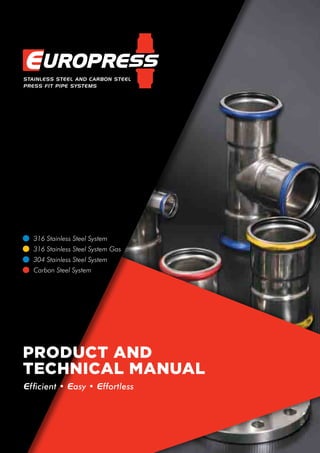
  • 1. Efficient • Easy • Effortless 304 Stainless Steel System Carbon Steel System 316 Stainless Steel System 316 Stainless Steel System Gas product and technical manual
  • 2. The EUROPRESS Pressfitting System is an extremely fast and simple assembly system, producing reliable joints with high mechanical resistance, for civil, industrial and naval pipework system installations. Standard diameters range from 15 to 108 mm. Other sizes are available for special applications. 1.1 MATERIALS Depending on the application, the following materials are used: • stainless steel 316L • stainless steel 304 • carbon steel 1.2 BENEFITS The main benefits of the Europress System are: • fast and easy assembly • reliable, secure and long-lasting seals • no fire risk during installation • high corrosion resistance using 316 Stainless Steel INTRODUCTION Europress reserves the right to make improvements. Data may change without prior notice This manual and its contents are protected by legislation related to Intellectual Property and as such cannot be reproduced in whole or in part unless with written authorisation. PRESS CHECK SLEEVES Europress are at the forefront of pressing systems with the innovative Press check sleeve. Rather than wait to fill an installation with fluid to see if any joint leaks because it has not been pressed, Europress fittings up to and includ- ing 54mm have a thin coloured film applied externally on the O ring seat. When the joint is pressed the film is shredded and detaches from the fitting for easy removal and visual witness to the completed press cycle. Blue sleeves – Stainless steel Yellow sleeves – Gas fittings Red sleeves – Carbon steel fittings This Technical Manual provides basic information as a guide. It remains the responsibility of the user to ascertain the suitability and compatibility with their specific application. 2
  • 3. 1 INTRODUCTION 2 1.1 Materials 1.2 Benefits 1.3 INDEX 3 1.4 Features and Benefits 4 - 5 1.4 The Europress Pressfit System 6 2 STAINLESS STEEL EUROPRESS PRESSFITTING SYSTEM 2.1 Stainless Steel Pipes 7 2.2 Stainless Steel Pressfittings 7 2.3 General Applications 7 2.4 Gas Applications 7 3 EUROPRESS CARBON STEEL SYSTEM 3.1 Pipes and Pressfittings 7 4 STAINLESS STEEL PRESSFITTINGS 4.1 Standard Fittings 8 - 20 4.2 Stainless Steel Super Size Fittings 21 - 22 4.3 S.S. Backing Rings and Flanges 23 - 24 4.5 Gas Fittings 25 - 31 4.6 S.S. Backing Rings and Flanges 32 - 33 5 CARBON STEEL PRESSFITTINGS 5.1 Standard Fittings 34 - 43 5.2 Galvanised Threaded Flanges 44 6 AUXILIARY 6.1 Gaskets 45 - 47 6.2 O Rings 48 6.3 Flat Gaskets 49 6.5 Kova Clips 50 - 54 6.6 Bolted Clips 55 7 TOOLS 7.1 Pressing Tools 56 - 62 7.5 Pipe Tools 63 - 64 8 PIPE LAYING AND EXPANSION 8.1 Expansion 65 - 67 8.4 Pipe Fixing 68 - 69 8.5 Corrosion Resistance 70 8.7 Testing 70 8.8 Noise Insulation 70 8.9 Thermal Insulation 70 9 GUARANTEE 70 10 PROXIMITY TABLES 71 - 72 11 CHEMICAL COMPATIBILITY 73 12 PIPE SIZING 74 13 TROUBLESHOOTING 74 14 FLOW TABLES 75 - 81 15 INSTALLATION INSTRUCTIONS 82 - 83 3
  • 4. Europress reserves the right to make improvements. Data may change without prior notice 4 features and benefits of the Europress 316L polished S/S tubing for a superior finish. High alloy austenitic Cr-Ni-Mo Fittings made from the same high grade 316 S/S with a choice of O-Rings for chemical suitability. The speed of a pressfit system will amaze you. Competent tradesmen can install a press fit system without the need of qualified welders. • Faster and Cheaper • Less time on the job • Cuts Costs up to 30% 25 Year Manufacturer backed product guarantee for all approved applications. Additionally, pressfit tightness is guaranteed by the manufacturer to be in excess of 30 years. The Europress System is designed for use with common "M" profile Press Jaws, the system is bulk stocked in a number of locations Australia wide and is available through many Plumbing and Industrial outlets.
  • 5. Press Fit System 5 Using Press fittings is up to 10 times faster than conventional Tig welding techniques for stainless steel. No need to completely drain pipe contents prior to alterations. Press Fittings can be crimped wet or dry. Pressing Tool with inbuilt safety features ensures each press is the same every time, no uncertainty of weld integrity. With the innovative Press Check Sleeve you don't have to wait until the system is full of product to discover leaks! The Press Check Sleeve, makes it easy to immediately identify any joints that have not been pressed. NO NAKED FLAME NO HOT WORK PERMITS NO GAS BOTTLES No fire hazard or heavy installation equipment, makes it easier to comply with OH&S requirements.
  • 6. Europress reserves the right to make improvements. Data may change without prior notice 1.4 THE EUROPRESS PRESSFIT SYSTEM The Europress Press Fit System is the ideal solution for installing Stainless Steel or Carbon Steel pipework. Pressfitted pipe joints are fast, easy and risk-free. Standard Europress Pipe is available in O.D. tube sizes – 15, 22, 28, 35, 42, 54, 76.1, 88.9, & 108 This Technical Manual provides basic information as a guide. It remains the responsibility of the user to ascertain the suitability and compatibility with their specific application. The pipe is pushed into the fitting, up to the stop, then the jaw attachments of the pressing tool press the toroidal end of the fitting into the pipe. Pressing produces two deformations. The first, radial deformation, compresses the 0-ring in the toroidal chamber and guarantees that the pipe is hermetically sealed. The second, geometric deformation of both fitting and pipe, creates a mechanical joint, resistant to slipping and rotation. The resulting pressing profile varies according to diameter. Fig 1 shows an assembled joint before and after pressing. Joints produced in this way are extremely strong, but flexible enough to withstand the stresses resulting from initial installation and those, such as vibrations and thermal expansion etc., that occurs in normal operating conditions. This is provided that installation has been carried out according to the instructions in this manual. Certifications The Europress 316L Stainless Steel pipe and standard fittings have been certified for drinking water use by many national and international authorities. Notably it exceeds the demanding quality requirements of the Australian Watermark and the German Standard DVGW W534. 2.0 EUROPRESS STAINLESS STEEL All 316L pipes and pressfittings are made of austenitic stainless Cr- Ni-Mo steel, n. 1.4404 which conforms to Standard UNI EN 10088 (AISI 316L ). 304 grade SS pipe n. 1.4307 is available as a more economic alternative to 316L. The nominal dimension used to identify both components of the joint refers to the outside diameter of the pipe. 2.1 PIPES Pipes for use in mains systems are manufactured to AS 5200.053 and conform to Standard DVGW- GW 547/2004 and are marked as such. Dimensional tolerances conform to Standard EN ISO 1127 D4/T4. These pipes are sold in 6-metre lengths and are capped both ends. Watermark AS 3688 AS 5200.053 WMKA22265 Activfire AS 4118.2.1 VdS2344en VdS2100-26en Fig. 1 Joining of pressfitting on pipe Pressfitting O-ring Pipe Before pressing After pressing Profile view Outside diam mm 15 22 28 35 42 54 76.1 88.9 108 139.7 168.3 Thickness 1 1.2 1.2 1.5 1.5 1.5 2 2 2 2 2 6
  • 7. 2.2 STAINLESS STEEL PRESSFITTINGS Press fittings are manufactured from the same material as the pipes and conform to AS 3688 The special process used to make the press fittings can be broken down into the following main stages: • cutting the pipe into sections and mechanical working • forming the toroidal seat • any welding of other parts of the fitting • heat treatment in a controlled atmosphere at 1050°C to restore the material’s original characteristics All process stages conform to Standards UNI EN ISO 9001 and in compliance with related technical specifications from DVGW, VdS, etc. 2.3 GENERAL APPLICATIONS The Europress Stainless Steel system is the ideal solution for drinking water systems as the AlSI 316L stainless steel used is completely hygienic and highly corrosion resistant. The standard o-rings made of black EPDM, are resistant to aging, heat and chemical additives and are particularly suitable for all types of treated water. The reliable, high-quality components are suitable for heating, cooling, compressed air, oil and diesel lines in the civil, industrial and manufacturing sectors. Conditions of use • Maximum operating pressure: 16 bar • Operating temperature: -20°C +95°C • Maximum temperature: 120°C (On approved applications.) • Up to 40 Bar/580 psi available on approved applications. Please refer to technical department. The Europress Pressfitting System complies with the CSIRO ACTIVFIRE certification and has been evaluated and verified as conforming to AS 4118.2.1-1995. It also has been granted the internationally recognized VdS- certification for fire extinguisher systems according to VdS CEA 4001 for both carbon steel and stainless steel products 22mm-108mm (DN20-DN100). 2.4 GAS APPLICATION The Europress System meets AS 5200.053 and is approved in Australia, New Zealand and many European countries for use in gas distribution systems, with external above-ground pipes, installed inside or outside buildings. It can be used for all types of combustible gas, both natural and liquid. The O-ring gaskets are made of yellow HNBR, and are compatible with any of the gas varieties used and are resistant to ageing and heat. Conditions of use • Maximum operating pressure: 5 bar • Operating temperature: -20 °C +70 °C Certification The Europress pressfittings comply with AS NZS 5601.1.2013 which requires certification as conforming to the German Standard DVGW VP614 for gas applications. To conform to this standard, each of the welded fittings, complete with o-rings, undergoes a special helium test. These fittings have a yellow label with the letters “PN5” or equivalent yellow mark, to indicate their application. 3. EUROPRESS CARBON STEEL 3.1 Pipes and pressfittings All pipes and pressfitting are made of carbon steel, E195 or E235 n. 1.0034 which conforms to Standard EN 10305. The nominal dimension used to identify both components of the joint refers to the outside diameter of the pipe. The following range of diameters and thicknesses can be used: Pipes are sold in 6-metre lengths and dimensional tolerances must conform to Standard EN I0305. Pressfitting The types of pressfittings available are listed in p 34–43 The special process used to make the press fittings can be broken down into the following main stages: •cutting the pipe into sections and mechanical working •forming the toroidal seat •any welding of other parts of the fitting •any annealing heat treatments •zinc surface treatments All process stages are subjected to a quality certified system conforming to Standard UN1 EN ISO 9001/2000. Marking All Europress pipes and press fittings are stamped in accordance with the relevant standard to indicate their application. 3.2 Various applications The Europress Pressfit System in carbon steel is indicated for use in various types of civil and industrial installations where stainless steel pipework is not essential. Typical applications are: •closed-circuit heating and cooling water systems •compressed air and inert gas systems •closed-circuit sprinkler systems •oil and diesel lines. All applications should be checked with Europress Technical department. The O-ring gaskets, made of black EPDM, are resistant to ageing, heat and chemical additives and are therefore particularly suitable for all types of treated water. Conditions of use •Maximum operating pressure: 16 bar •Operating temperature: -20°C +85°C •Maximum temperature: 120°C (On approved applications. Please refer to tech. dept.) Outside diam mm 15 22 28 35 42 54 76.1 88.9 108 Thickness 1.2 1.2 1.2 1.5 1.5 1.5 2 2 2 7
  • 8. Europress reserves the right to make improvements. Data may change without prior notice Part No. d L Z weight gram SPP0.000015 15 52 10 39 SPP0.000022 22 59 13 62 SPP0.000028 28 61 13 78 SPP0.000035 35 72 18 109 SPP0.000042 42 79 15 147 SPP0.000054 54 90 16 205 SPP0.000076 76.1 142 32 604 SPP0.000089 88.9 163 37 837 SPP0.000108 108 192 38 1,193 Coupling Part No. d-d1 L H weight gram SSP0.022015 22-15 60 39 45 SSP0.028015 28-15 72 51 56 SSP0.028022 28-22 67 44 65 SSP0.035015 35-15 82 61 89 SSP0.035022 35-22 83 60 98 SSP0.035028 35-28 73 49 112 SSP0.042015 42-15 91 70 118 SSP0.042022 42-22 87 64 125 SSP0.042028 42-28 98 74 140 SSP0.042035 42-35 79 52 120 SSP0.054015 54-15 110 89 197 SSP0.054022 54-22 107 84 191 SSP0.054028 54-28 99 75 193 SSP0.054035 54-35 128 101 237 SSP0.054042 54-42 97 65 191 SSP0.076042 76,1-42 151 119 425 SSP0.076054 76,1-54 140 103 451 SSP0.089054 88,9-54 156 119 586 SSP0.089076 88,9-76,1 156 101 653 SSP0.108054 108-54 204 167 880 SSP0.108076 108-76,1 196 141 978 SSP0.108089 108-88,9 190 127 992 Reducing Coupling (Spigot x Adaptor) Other Sizes Available Stainless steel pipes type 1.4404 (316L) with Watermarked approval for potable water Pipe–Austenitic – 6 metre lengths Part No. 316L 304 ext. Ø [mm] thickness [mm] length [m] weight [kg/m] STT0.316015 STT0.304015 15 1 6 0.351 STT0.316022 STT0.304022 22 1.2 6 0.625 STT0.316028 STT0.304028 28 1.2 6 0.805 STT0.316035 STT0.304035 35 1.5 6 1.258 STT0.316042 STT0.304042 42 1.5 6 1.521 STT0.316054 STT0.304054 54 1.5 6 1.972 STT0.316076 STT0.304076 76.1 2 6 3.711 STT0.316089 STT0.304089 88.9 2 6 4.352 STT0.316108 STT0.304108 108 2 6 5.308 4.0 STAINLESS STEEL AISI 316L 4.0 8
  • 9. Part No. d L Z weight gram Radius SPP9.000015 15 48 27 57 1.5d SPP9.000022 22 60 37 97 1.5d SPP9.000028 28 71 47 143 1.5d SPP9.000035 35 87 60 198 1.5d SPP8.000035 35 75 48 173 1.2d SPP9.000042 42 15 83 314 1.5d SPP8.000042 42 89 57 261 1.2d SPP9.000054 54 142 105 499 1.5d SPP8.000054 54 107 70 391 1.2d SPP8.000076 76.1 150 95 977 1.2d SPP8.000089 88.9 174 111 1,325 1.2d SPP8.000108 108 215 138 2,091 1.2d Elbow 90° Part No. d L Z weight gram Radius SPP4.000015 15 37 16 49 1.5d SPP4.000022 22 44 21 81 1.5d SPP4.000028 28 51 27 118 1.5d SPP4.000035 35 59 32 161 1.5d SPP2.000035 35 49 22 152 1.2d SPP4.000042 42 77 45 254 1.5d SPP2.000042 42 63 31 216 1.2d SPP4.000054 54 88 51 369 1.5d SPP2.000054 54 75 38 323 1.2d SPP2.000076 76.1 98 43 773 1.2d SPP2.000089 88.9 112 49 991 1.2d SPP2.000108 108 138 61 1,600 1.2d Elbow 45° Part No. d L H Z weight gram Radius SPS9.000015 15 48 56 27 58 1.5d SPS9.000022 22 60 68 37 98 1.5d SPS9.000028 28 71 80 47 147 1.5d SPS9.000035 35 87 93 60 200 1.5d SPS8.000035 35 75 83 48 179 1.2d SPS9.000042 42 115 125 83 331 1.5d SPS8.000042 42 89 97 57 260 1.2d SPS9.000054 54 142 149 105 505 1.5d SPS8.000054 54 107 116 70 400 1.2d SPS8.000076 76.1 150 165 95 982 1.2d SPS8.000089 88.9 174 190 111 1,317 1.2d SPS8.000108 108 215 238 138 2,068 1.2d Elbow 90° with Spigot End Part No. d L E weight gram SPPS.000015 15 71 24 47 SPPS.000022 22 82 27 85 SPPS.000028 28 90 28 114 SPPS.000035 35 99 31 149 SPPS.000042 42 115 35 216 SPPS.000054 54 139 40 316 SPPS.000076 76.1 230 60 874 SPPS.000089 88.9 258 70 1,196 SPPS.000108 108 305 80 1,775 Slip Coupling 9
  • 10. Europress reserves the right to make improvements. Data may change without prior notice Part No. d L H Z weight gram Radius SPS4.000015 15 37 48 16 53 1.5d SPS4.000022 22 44 53 21 85 1.5d SPS4.000028 28 51 60 27 117 1.5d SPS4.000035 35 59 66 32 160 1.5d SPS2.000035 35 49 51 22 155 1.2d SPS4.000042 42 77 80 45 237 1.5d SPS2.000042 42 63 72 31 203 1.2d SPS4.000054 54 88 97 51 366 1.5d SPS2.000054 54 75 83 38 310 1.2d SPS2.000076 76.1 98 117 43 767 1.2d SPS2.000089 88.9 112 131 49 998 1.2d SPS2.000108 108 138 154 61 1,510 1.2d Elbow 45° with Spigot End Part No. d-Rp L L1 H weight gram SPF9.015015 15-½ 48 58 27 76 SPF9.022020 22-¾ 60 68 37 123 SPF9.028025 28-1 71 81 47 172 SPF9.035032 35-1¼ 87 95 60 267 Elbow Adaptor 90° with Female Thread Part No. d-R L L1 H weight gram SPM9.015015 15-½ 48 58 27 75 SPM9.022020 22-¾ 60 69 37 119 SPM9.028025 28-1 71 81 47 184 SPM9.035032 35-1¼ 87 94 60 262 SPM9.042040 42-1½ 115 116 83 376 SPM9.054050 54-2 142 143 105 667 Elbow Adaptor 90° with Male Thread Part No. d-R L L1 H weight gram SPM4.015015 15- ½ 37 38 16 64 SPM4.022020 22- ¾ 44 51 21 102 Elbow Adaptor 45° with Male Thread 4.0 STAINLESS STEEL AISI 316L STANDARD FITTINGS 10
  • 11. Part No. d-G L L1 Z I I1 H g weight [ISO 228] gram SPFL.015015 15-½ 46 43 25 12 12 34 5 104 SPFL.022020 22-¾ 52 51 29 16 13 40 6 147 90° Female Elbow with Flush Wall Mount Part No. d-R L H Z weight gram SSFA.015015 15 -½ 35 53 23 66 Elbow 90 Spigot with Female Thread Part No. d-R L H Z Z1 weight gram SPFA.015015 15-½ 53 36 32 24 121 SPFA.022020 22 - ¾ 57 46 34 33 180 SPFA.028025 28-1 71 54 47 38 329 SPFA.035032 35 - 1¼ 72 62 45 45 455 Elbow Adaptor 90° with Female Thread Part No. d-R L H Z weight gram SPMA.015015 15-½ 53 36 32 91 SPMA.015020 15-¾ 62 38 41 137 SPMA.022020 22-¾ 58 40 35 145 SPMA.028025 28-1 63 44 39 245 SPMA.035032 35-1¼ 71 48 44 338 SPMA.042040 42-1½ 81 53 49 425 SPMA.054050 54-2 92 59 55 716 Elbow Adaptor 90° with Male Thread 11 SPFW.015015 15-½ 46 36 65 25 12 148 SPFW.022020 22-¾ 52 2 65 29 13 176 90° Female Elbow with Extended Offset Wall Mount Part No. d-G L I L1 z I1 weight [ISO 228] gram
  • 12. Europress reserves the right to make improvements. Data may change without prior notice Part No. d L L1 Z Z1 I weight gram SPPT.000015 15 74 35 16 14 37 67 SPPT.000022 22 82 40 18 17 41 112 SPPT.000028 28 92 45 22 21 46 149 SPPT.000035 35 102 55 24 28 51 189 SPPT.000042 42 118 61 27 29 59 27 SPPT.000054 54 142 72 34 35 71 382 SPPT.000076 76.1 232 115 61 60 116 1,192 SPPT.000089 88.9 262 127 68 64 131 1,617 SPPT.000108 108 312 155 79 78 156 2,450 Equal Tee Part No. d-d1-d L L1 Z Z1 I weight gram SPPT.022015 22-15-22 82 39 18 18 41 98 SPPT.028015 28-15-28 92 42 22 21 46 130 SPPT.028022 28-22-28 92 45 22 22 46 140 SPPT.035015 35-15-35 102 45 24 24 51 164 SPPT.035022 35-22-35 102 46 24 23 51 172 SPPT.035028 35-28-35 102 48 24 24 51 175 SPPT.042015 42-15-42 118 48 27 27 59 213 SPPT.042022 42-22-42 118 51 27 28 59 239 SPPT.042028 42-28-42 118 53 27 29 59 240 SPPT.042035 42-35-42 118 60 27 33 59 242 SPPT.054015 54-15-54 142 56 34 35 71 326 SPPT.054022 54-22-54 142 57 34 34 71 325 SPPT.054028 54-28-54 142 60 34 36 71 348 SPPT.054035 54-35-54 142 66 34 39 71 344 SPPT.054042 54-42-54 142 64 34 32 71 368 SPPT.076022 76.1-22-76.1 232 68 61 45 116 942 SPPT.076028 76.1-28-76.1 232 71 61 47 116 956 SPPT.076035 76.1-35-76.1 232 75 61 48 116 968 SPPT.076042 76.1-42-76.1 232 79 61 47 116 981 SPPT.076054 76.1-54-76.1 232 80 61 43 116 1,067 SPPT.089022 88.9-22-88.9 262 76 68 53 131 1,256 SPPT.089028 88.9-28-88.9 262 76 68 52 131 1,244 SPPT.089035 88.9-35-88.9 262 83 68 56 131 1,267 SPPT.089042 88.9-42-88.9 262 85 68 53 131 1,271 SPPT.089054 88.9-54-88.9 262 93 68 56 131 1,297 SPPT.089076 88.9-76.1-88.9 262 116 68 61 131 1,479 SPPT.108022 108-22-108 312 85 79 62 156 1,919 SPPT.108028 108-28-108 312 88 79 64 156 1,939 SPPT.108032 108-35-108 312 94 79 67 156 1,955 SPPT.108042 108-42-108 312 96 79 64 156 1,886 SPPT.108054 108-54-108 312 102 79 65 156 1,967 SPPT.108076 108-76.1-108 312 125 79 70 156 2,147 SPPT.108089 108-88.9-108 312 135 79 72 156 2,255 Reducing Tee 4.0 STAINLESS STEEL AISI 316L STANDARD FITTINGS 12
  • 13. Part No. d-Rp L L1 Z Z1 I weight gram SPFT.015015 15-½-15 74 37 16 25 37 83 SPFT.022015 22-½-22 82 41 18 29 41 117 SPFT.022020 22-¾-22 82 41 18 28 41 131 SPFT.028015 28-½-28 92 44 22 32 46 144 SPFT.028020 28-¾-28 92 45 22 32 46 159 SPFT.028025 28-1-28 92 48 22 32 46 175 SPFT.035015 35-½-35 102 48 24 36 51 178 SPFT.035020 35-¾-35 102 48 24 35 51 189 SPFT.035032 35-1¼-35 102 57 24 40 51 255 SPFT.042015 42-½-42 118 46 27 34 59 240 SPFT.042020 42-¾-42 118 52 27 39 59 254 SPFT.042040 42-1½-42 118 59 27 42 59 384 SPFT.054015 54-½-54 142 55 34 43 71 362 SPFT.054020 54-¾-54 142 58 34 45 71 364 SPFT.054050 54-2-54 142 69 34 47 71 523 SPFT.076020 76.1-¾-76.1 232 68 61 55 116 1,009 SPFT.076050 76.1-2-76.1 232 81 61 59 116 1,194 SPFT.089020 88.9-¾-88.9 262 87 68 74 131 1,210 SPFT.089050 88.9-2-88.9 262 88 68 66 131 1,450 SPFT.108020 108-¾-108 312 86 79 73 156 1,956 SPFT.108050 108-2-108 312 98 79 76 156 2,118 Female Centred Tee Male Centred Tee Part No. d L L1 Z Z1 I weight gram SPMT.015015 15-½ -15 74 38 16 15 37 75 SPMT.022020 22-¾-22 82 43 18 17 41 105 SPMT.028025 28-1-28 92 50 22 21 46 130 SPMT.035032 35-1¼-35 102 56 24 28 51 170 Part No. d-Rp L H weight gram SSF0.015015 15-½ 136 148 95 SSF0.022015 22-½ 140 152 150 SSF0.022020 22-¾ 139 152 148 SSF0.028025 28-1 94 110 145 SSF0.035032 35-1¼ 93 110 210 SSF0.042040 42-1½ 93 110 300 SSF0.054050 54-2 98 120 408 Adaptor with Female Thread and Spigot End 13
  • 14. Europress reserves the right to make improvements. Data may change without prior notice Part No. d-Rp L H weight gram SPF0.015015 15-½ 53 20 52 SPF0.015020 15-¾ 67 33 81 SPF0.022015 22-½ 52 17 77 SPF0.022020 22-¾ 56 20 75 SPF0.022025 22-1 70 31 105 SPF0.028020 28-¾ 73 36 105 SPF0.028025 28-1 62 22 103 SPF0.028032 28-1¼ 80 39 171 SPF0.035025 35-1 81 38 136 SPF0.035032 35-1¼ 72 28 170 SPF0.035040 35-1½ 83 39 259 SPF0.042032 42-1¼ 94 45 221 SPF0.042040 42-1½ 74 25 252 SPF0.054040 54-1½ 106 52 328 SPF0.054050 54-2 84 25 342 Adaptor with Female Thread Part No. d-R L H weight gram SPM0.015010 15-3 /8 50 29 50 SPM0.015015 15-½ 52 31 52 SPM0.015020 15-¾ 64 43 66 SPM0.022015 22-½ 68 45 73 SPM0.022020 22-¾ 58 35 74 SPM0.022025 22-1 72 49 116 SPM0.028020 28-¾ 73 49 100 SPM0.028025 28-1 62 38 115 SPM0.028032 28-1¼ 79 55 166 SPM0.035025 35-1 82 55 148 SPM0.035032 35-1¼ 70 43 165 SPM0.035040 35-1½ 84 57 198 SPM0.042032 42-1¼ 93 61 216 SPM0.042040 42-1½ 75 43 204 SPM0.054040 54-1½ 105 68 271 SPM0.054050 54-2 87 50 368 SPM0.076065 76.1- 2½ 125 70 820 SPM0.089080 88.9- 3 138 75 1,158 Adaptor with Male Thread Part No. d-R L weight gram SSM0.015015 15-½ 70 55 SSM0.022020 22-¾ 75 80 SSM0.028025 28-1 75 120 SSM0.035032 35-1¼ 80 170 SSM0.042040 42-1½ 91 220 SSM0.054050 54-2 102 384 Adaptor with Male Thread and Spigot End 4.0 STAINLESS STEEL AISI 316L STANDARD FITTINGS 14
  • 15. Part No. d-G L L1 Z Z1 H I I1 weight gram SPFM.015015 15-½ 74 43 21 31 34 12 13 130 Off Centred Tee with Female Thread Part No. d-G L L1 I I1 Z H weight gram SPFC.015015 15-½ 56 44 15 12 35 139 166 Lugged Elbow with Female Tap Outlet Part No. D-RP NUT L Z weight gram SPFN.015015 15-½ ST. STEEL 73 40 139 SPFN.015020 15-¾ ST. STEEL 75 41 176 SPFN.022020 22-¾ ST. STEEL 76 40 205 SPFN.022025 22-1 ST. STEEL 79 40 235 SPFN.028025 28-1 ST. STEEL 83 43 387 SPFN.035032 35-1¼ ST. STEEL 93 49 448 SPFN.042040 42-1½ ST. STEEL 96 47 542 SPFN.054050 54-2 ST. STEEL 113 54 943 Part No. D-RP NUT L Z weight gram SPFQ.015015 15-½ BRASS 73 40 145 SPFQ.015020 15-¾ BRASS 75 41 182 SPFQ.022020 22-¾ BRASS 76 40 212 SPFQ.022025 22-1 BRASS 79 40 242 SPFQ.028025 28-1 BRASS 83 43 398 SPFQ.035032 35-1¼ BRASS 93 49 467 SPFQ.042040 42-1½ BRASS 96 47 562 SPFQ.054050 54-2 BRASS 113 54 973 Female Barrel Union Brass / Stainless Steel Nut EPDM Flat Seal 15
  • 16. Europress reserves the right to make improvements. Data may change without prior notice Part No. D-RP NUT L H weight gram SPMN.015015 15 -½ ST. STEEL 76 55 141 SPMN.015020 15 -¾ ST. STEEL 80 59 160 SPMN.022015 22 -½ ST. STEEL 80 57 232 SPMN.022020 22 - ¾ ST. STEEL 82 59 215 SPMN.022025 22-1 ST. STEEL 86 63 249 SPMN.028025 28-1 ST. STEEL 88 64 349 SPMN.035032 35 - 1¼ ST. STEEL 100 73 525 SPMN.042040 42 - 1½ ST. STEEL 106 74 608 SPMN.054050 54 - 2 ST. STEEL 122 85 978 Part No. D-RP NUT L H weight gram SPMQ.015015 15-½ BRASS 76 55 147 SPMQ.015020 15-¾ BRASS 80 59 166 SPMQ.022015 22-½ BRASS 80 57 239 SPMQ.022020 22-¾ BRASS 82 59 222 SPMQ.022025 22-1 BRASS 86 63 256 SPMQ.028025 28-1 BRASS 88 64 360 SPMQ.035032 35-1¼ BRASS 100 73 544 SPMQ.042040 42-1½ BRASS 106 74 628 SPMQ.054050 54-2 BRASS 122 85 1008 Male Barrel Union Brass / Stainless Steel Nut EPDM Flat Seal Part No. D-RP NUT L Z weight gram SPPQ.015015 15 BRASS 97 55 170 SPPQ.022022 22 BRASS 105 59 222 SPPQ.028028 28 BRASS 111 63 345 SPPQ.035035 35 BRASS 124 70 540 SPPQ.042042 42 BRASS 134 70 640 SPPQ.054054 54 BRASS 144 70 970 Part No. D-RP NUT L Z weight gram SPPN.015015 15 ST. STEEL 97 55 154 SPPN.022022 22 ST. STEEL 105 59 215 SPPN.028028 28 ST. STEEL 111 63 334 SPPN.035035 35 ST. STEEL 124 70 521 SPPN.042042 42 ST. STEEL 134 70 620 SPPN.054054 54 ST. STEEL 144 70 940 Pipe - Pipe Barrel Union Brass / Stainless Steel Nut EPDM Flat 4.0 STAINLESS STEEL AISI 316L STANDARD FITTINGS 16
  • 17. Part No. d L Z weight gram SPE0.000015 15 37 16 27 SPE0.000022 22 41 18 44 SPE0.000028 28 46 22 63 SPE0.000035 35 51 24 81 SPE0.000042 42 59 27 119 SPE0.000054 54 72 35 171 SPE0.000076 76.1 95 40 427 SPE0.000089 88.9 107 44 559 SPE0.000108 108 127 50 821 Cap 3 Piece Ball Valve Adaptor Ends Part No. d L L1 C A M H weight gram SPPV.00015 15 118 48 22 20 105 57 454 SPPV.00022 22 133 51 31 21 110 67 860 SPPV.00028 28 147.9 55 37.9 24 130 85 1.054 SPPV.00035 35 177 65 47 27 130 85 1.922 SPPV.00042 42 205 74 57 32 160 100 2.584 SPPV.00054 54 228 80 68 38 160 110 3.500 SPPV.00076 76.1 316 115 86 55 235 130 9.180 SPPV.00089 88.9 346 124 98 64 245 140 12.98 SPPV.00108 108 432 153 126 78 330 170 20.24 Part No. d-D L Z weight gram SPR0.028025 28 x 33.7 87 63 171 SPR0.035032 35 x 42.4 94.5 67.5 239 SPR0.042040 42 x 48.3 105.5 73.5 298 SPR0.054050 54 x 60.3 124 87 429 SPR0.076065 76.1 x 76.1 150 95 986 SPR0.089080 88.9 x 88.9 165.5 102.5 1.229 SPR0.108100 108 x 114.4 184 107 1.393 Roll Groove Adaptor Imperial Weld Adaptor Part No. d1 D imp OD imp/mm L H weight gram SPBJ.015015 15 ½ 0.840/21.3 60 39 0.045 SPBJ.022020 22 ¾ 1.050/26.7 67 44 0.065 SPBJ.028025 28 1 1.315/33.4 73 49 0.112 SPBJ.035032 35 1¼ 1.900/42.2 79 52 0.12 SPBJ.042040 42 1½ 1.900/48.3 97 65 0.191 SPBJ.054050 54 2 2.375/60.3 140 103 0.451 SPBJ.076065 76.1 2½ 2.87/73.0 156 101 0.653 SPBJ.076080 76.1 3 3.50/88.9 190 127 0.653 SPBJ.089080 88.9 3 3.50/88.9 190 127 0.992 SPBJ.108100 108 4 4.50/114.3 184 107 1.393 17
  • 18. Europress reserves the right to make improvements. Data may change without prior notice Part No. d L D D1 Z C S weight gram SPJF.015015 15 38 34 14 17 4 10 57 SPJF.022020 22 39 39 21 16 4 9 70 SPJF.028025 28 42 45 27 18 4 9 89 SPJF.035032 35 46 56 32 19 4 9 127 SPJF.042040 42 50 62 39 18 4 9 156 Adaptor Flange (small) Part No. d L weight gram SPB0.000015 15 25 17 SPB0.000022 22 27 30 SPB0.000028 28 30 37 SPB0.000035 35 34 51 SPB0.000042 42 38 67 SPB0.000054 54 44 100 SPB0.000076 76 68 290 SPB0.000089 89 78 390 SPB0.000108 108 94 595 Welding Joint Part No. d Nominal flange size Inch size D P L T SPEF.015015 15 15 1/2” 95 67 30 6 SPEF.022020 22 20 3/4” 102 73 32 6 SPEF.028025 28 25 1” 114 83 36 7 SPEF.035032 35 32 1¼” 121 87 41 8 SPEF.042040 42 40 1½” 133 98 46 9 SPEF.054050 54 50 2” 152 114 50 10 SPEF.076080 76.1 80 3” 185 146 77 11 SPEF.089080 88.9 80 3” 185 146 91 11 SPEF.108100 108 100 4” 215 178 107 13 Adaptor Flange (large) Table E standard DIN ANSI available Part No. d D Z L T SSJF.076080 76.1 106 28 128 3 SSJF.089080 88.9 125 26 149 3 SSJF.108100 108 158 22 175 4 Stub Flange D P L T d 4.0 STAINLESS STEEL AISI 316L STANDARD FITTINGS 18 Use in conjunction with backing rings on page 23 Use in conjunction with backing rings on page 23
  • 19. 15° Bend Part No. d H1 H K K1 weight gram SSS1.000015 15 122 60 21 83 76 SSS1.000022 22 124 50 7 81 110 SSS1.000028 28 136 45 7 47 146 SSS1.000035 35 234 62 30 110 381 SSS1.000042 42 276 94 41 144 558 SSS1.000054 54 337 117 65 165 869 SSS1.000076 76.1 230 226 65 65 1.607 SSS1.000089 88.9 260 240 80 80 2.109 SSS1.000108 108 291 222 95 95 2.546 30° Bend Part No. d H1 H K K1 weight gram SSS3.000015 15 122 60 21 83 76 SSS3.000022 22 124 50 6 80 110 SSS3.000028 28 130 54 7 47 144 SSS3.000035 35 218 80 30 110 382 SSS3.000042 42 274 98 44 144 560 SSS3.000054 54 324 137 65 165 905 SSS3.000076 76.1 200 202 66 66 1.41 SSS3.000089 88.9 262 264 80 80 2.183 SSS3.000108 108 259 272 95 95 2.622 45° Bend Part No. d H1 H K K1 weight gram SSS4.000015 15 120 62 19 77 76 SSS4.000022 22 120 56 7 71 111 SSS4.000028 28 122 58 2 66 146 SSS4.000035 35 206 94 20 132 380 SSS4.000042 42 262 114 1 149 576 SSS4.000054 54 321 146 37 212 928 SSS4.000076 76.1 225 225 69 69 1.577 SSS4.000089 88.9 267 267 103 103 2.323 SSS4.000108 108 293 293 66 66 2.901 60° Bend Part No. d H1 H K K1 weight gram SSS6.000015 15 122 60 21 83 76 SSS6.000022 22 118 60 5 63 112 SSS6.000028 28 116 71 7 47 140 SSS6.000035 35 226 101 30 110 383 SSS6.000042 42 251 124 44 145 564 SSS6.000054 54 308 162 65 165 889 SSS6.000076 76.1 219 223 70 70 1.479 SSS6.000089 88.9 250 257 80 80 1.996 SSS6.000108 108 288 298 95 95 2.78 19
  • 20. Europress reserves the right to make improvements. Data may change without prior notice 75° Bend Part No. d H1 H K K1 weight gram SSS7.000015 15 117 66 22 73 77 SSS7.000022 22 118 64 9 63 114 SSS7.000028 28 114 71 7 50 150 SSS7.000035 35 200 110 26 119 393 SSS7.000042 42 251 137 44 158 595 SSS7.000054 54 305 178 60 187 960 SSS7.000076 76.1 240 240 62 62 1.682 SSS7.000089 88.9 280 280 90 90 2.436 SSS7.000108 108 345 345 60 60 3.416 90° Bend Part No. d H1 H K K1 weight gram SSS9.000015 15 120 70 22 72 59 SSS9.000022 22 120 70 9 59 102 SSS9.000028 28 125 97 7 47 153 SSS9.000035 35 200 120 30 110 183 SSS9.000042 42 250 160 44 144 565 SSS9.000054 54 305 200 65 165 868 SSS9.000076 76.1 250 250 62 62 1.752 SSS9.000089 88.9 291 291 90 90 2.532 SSS9.000108 108 364 364 45 45 3.604 Pipe Bridge Part No. d L1 L2 L weight gram SSSB.000015 15 202 38 65 74 SSSB.000022 22 233 40 68 158 SSSB.000028 28 303 64 93 258 Pipe Bridge Short Part No. d L1 L2 L weight gram SSSZ.000015 15 145 37 57 54 SSSZ.000022 22 181 40 60 122 SSSZ.000028 28 241 55 83 215 4.0 STAINLESS STEEL AISI 316L STANDARD FITTINGS 20
  • 21. Pipe – Austenitic – 6 metre lengths 316 L Part No. DN Ext Ø (mm) Thickness (mm) weight kg/m STT0.316140 125 139.7 2 6.896 STT0.316168 150 168.3 2 8.328 304 Part No. DN Ext Ø (mm) Thickness (mm) weight kg/m STT0.304140 125 139.7 2 6.896 STT0.304168 150 168.3 2 8.328 Coupling 316 L Part No. d L Z weight kg SPP0.000140 139.7 258.5 62.3 2.031 SPP0.000168 168.3 308.8 72.6 2.835 304 Part No. d L Z weight kg RPP0.000140 139.7 258.5 62.3 2.031 RPP0.000168 168.3 308.8 72.6 2.835 Elbow 90° 316 L Part No. d Wall thickness L Z weight kg SPP9.000140 139.7 2.6 319.3 221.2 3.813 SPP9.000168 168.3 2.6 383.4 265.3 5.651 304 Part No. d Wall thickness L Z weight kg RPP9.000140 139.7 2.6 319.3 221.2 3.813 RPP9.000168 168.3 2.6 383.4 265.3 5.651 Elbow 45° 316 L Part No. d Wall thickness L Z weight kg SPP4.000140 139.7 2.6 208 109.9 1.906 SPP4.000168 168.3 2.6 249.3 131.2 2.825 304 Part No. d Wall thickness L Z weight kg RPP4.000140 139.7 2.6 208 109.9 1.906 RPP4.000168 168.3 2.6 249.3 131.2 2.825 Adaptor Flange 316 L Part No. d D P (pcd) L T Z weight kg SPEF.140125 139.7 250 210 144 25 46 3.26 SPEF.168150 168.3 285 235 170 26 53 3.94 304 Part No. d D P (pcd) L T Z weight kg RPEF.140125 139.7 250 210 144 25 46 3.26 RPEF.168150 168.3 285 235 170 26 53 3.94 4.2 STAINLESS STEEL AISI 316L SUPER SIZES 21
  • 22. Europress reserves the right to make improvements. Data may change without prior notice Equal Tee 316 L Part No. d Wall thickness L L1 Z Z1 I weight kg SPPT.000140 139.7 2.6 433 192 98.5 93.9 216.5 3.94 SPPT.000168 168.3 2.6 520 243.6 118 125.1 260 5.69 304 Part No. d Wall thickness L L1 Z Z1 I weight kg RPPT.000140 139.7 2.6 433 192 98.5 93.9 216.5 3.94 RPPT.000168 168.3 2.6 520 243.6 118 125.1 260 5.69 Reducing Tee 316 L Part No. d d1 L L1 Z Z1 I weight kg SPPT.140076 139.7 76.1 433 145 98.5 90.4 216.5 3.33 SPPT.140089 139.7 88.9 433 155 98.5 97.4 216.5 3.62 SPPT.140108 139.7 108 433 171 98.5 100 216.5 3.65 SPPT.168076 168.3 76.1 520 160 118 105.4 260 4.71 SPPT.168089 168.3 88.9 520 170 118 112.4 260 4.71 SPPT.168108 168.3 108 520 186 118 114.7 260 4.93 SPPT.168140 168.3 139.7 520 218 118 120 260 5.22 304 Part No. d d1 L L1 Z Z1 I weight kg RPPT.140076 139.7 76.1 433 145 98.5 90.4 216.5 3.33 RPPT.140089 139.7 88.9 433 155 98.5 97.4 216.5 3.62 RPPT.140108 139.7 108 433 171 98.5 100 216.5 3.65 RPPT.168076 168.3 76.1 520 160 118 105.4 260 4.71 RPPT.168089 168.3 88.9 520 170 118 112.4 260 4.71 RPPT.168108 168.3 108 520 186 118 114.7 260 4.93 RPPT.168140 168.3 139.7 520 218 118 120 260 5.22 Reducing Coupler (Spigot x Adaptor) 316 L Part No. d d1 # L H Kg SSP0.140089 139.7 88.9 2.6 363 305.4 2.22 SSP0.140108 139.7 108 2.6 – – 2.1 SSP0.168089 168.3 88.9 2.6 470 421.4 3.23 SSP0.168108 168.3 108 2.6 – – 3.11 SSP0.168140 168.3 139.7 2.6 365.3 267.2 2.93 304 Part No. d d1 # L H Kg RSP0.140089 139.7 88.9 2.6 363 305.4 2.22 RSP0.140108 139.7 108 2.6 – – 2.1 RSP0.168089 168.3 88.9 2.6 470 421.4 3.23 RSP0.168108 168.3 108 2.6 – – 3.11 RSP0.168140 168.3 139.7 2.6 365.3 267.2 2.93 4.2 SUPER SIZES 22
  • 23. Part No Pipe size d Nominal flange size Inch size P (mm) A (mm) D (mm) T (mm) Bolt holes No. x dia Bolt SBE6.000015 15 15 1/2” 67.0 29 95 6.0 4 x 14 M12 SBE6.000020 22 20 3/4” 73.0 34 100 6.0 4 x 14 M12 SBE6.000025 28 25 1” 83.0 40 115 7.0 4 x 14 M12 SBE6.000035 35 32 1¼” 87.0 46 120 8.0 4 x 14 M12 SBE6.000040 42 40 1½” 98.0 54 135 9.0 4 x 14 M12 SBE6.000050 SBE6.000075 76.1 65 2½” 127 76.1 165 10.0 4 x 18 M16 SBE6.000089 88.9 80 3” 146.0 88.9 184 11.0 4 x 18 M16 SBE6.000100 108 100 4” 178.0 114.3 216 13.0 8 x 18 M16 TABLE E Backing Rings – B16.5a 1992– Table ASA.150 Size not relevant For Backing Rings in 304 grade – change 6 to 4 23 Part No Pipe size d Nominal flange size Inch size P (mm) A (mm) D (mm) T (mm) Bolt holes No. x dia Bolt SBA6.000015 15 15 1/2” 60.5 29 90 11.5 4 x 16 M12 SBA6.000020 22 20 3/4” 70.0 34 98 13.0 4 x 16 M12 SBA6.000025 28 25 1” 79.5 40 108 14.5 4 x 16 M12 SBA6.000035 35 32 1¼” 89.0 46 117 16.0 4 x 16 M12 SBA6.000040 42 40 1½” 98.5 54 127 17.5 4 x 16 M12 SBA6.000050 SBA6.000075 76.1 65 2½” 139.5 83 178 22.5 4 x 20 M16 SBA6.000089 88.9 80 3” 152.5 97 191 24.0 4 x 20 M16 SBA6.000100 108 100 4” 190.5 110 229 24.0 8 X 20 M16 ANSI Backing Rings – CLASS 150 For Backing Rings in 304 grade – change 6 to 4 Size not relevant 4.3 BACKING RINGS FLANGES Part No Pipe size d Nominal flange size Inch size P (mm) A (mm) D (mm) T (mm) Bolt holes No. x dia Bolt SBD6.000015 15 15 1/2” 65.0 29 95 14.0 4 x 14 M12 SBD6.000020 22 20 3/4” 75.0 34 105 16.0 4 x 14 M12 SBD6.000025 28 25 1” 85.0 40 115 16.0 4 x 14 M12 SBD6.000035 35 32 1¼” 100.0 46 140 18.0 4 x 18 M16 SBD6.000040 42 40 1½” 110.0 54 150 18.0 4 x 18 M16 SBD6.000050 SBD6.000075 76.1 80 3” 145.0 83 185 20.0 8 x 18 M16 SBD6.000089 88.9 80 3” 160.0 97 200 20.0 8 x 18 M16 SBD6.000100 108 100 4” 180.0 110 220 22.0 8 x 18 M16 DIN Backing Rings – EN 1092–1 For Backing Rings in 304 grade – change 6 to 4 Size not relevant
  • 24. Europress reserves the right to make improvements. Data may change without prior notice Part No Nominal flange size Inch size P (mm) D (mm) T (mm) G (mm) Bolt holes No. x dia Bolt SFD6.000015 15 1/2” 65.0 95 16.0 2.0 4 x 14 M12 SFD6.000020 20 3/4” 75.0 105 18.0 2.0 4 x 14 M12 SFD6.000025 25 1” 85.0 115 18.0 2.0 4 x 14 M12 SFD6.000035 32 1¼” 100.0 140 18.0 2.0 4 x 18 M16 SFD6.000040 40 1½” 110.0 150 18.0 3.0 4 x 18 M16 SFD6.000050 50 2” 125.0 165 18.0 3.0 4 x 18 M16 SFD6.000065 65 2½” 145.0 185 22.0 3.0 8 x 18 M16 SFD6.000075 80 3” 160.0 200 22.0 3.0 8 x 18 M16 SFD6.000100 100 4” 180.0 220 22.0 3.0 8 x 18 M16 SFD6.000125 125 5” 210.0 250 22.0 3.0 8 x18 M16 SFD6.000150 150 6” 240.0 285 24.0 3.0 8 x 22 M20 DIN Scr Flanges EN 1092-1 For Screwed Flanges in 304 grade – change 6 to 4 Part No Nominal flange size Inch size P (mm) D (mm) T (mm) G (mm) Bolt holes No. x dia Bolt SFA6.000015 15 1/2” 60.5 90 14 1.6 4 x 16 M12 SFA6.000020 20 3/4” 70.0 99 14 1.6 4 x 16 M12 SFA6.000025 25 1” 79.5 108 16 1.6 4 x 16 M12 SFA6.000035 32 1¼” 89.0 117 19 1.6 4 x 16 M12 SFA6.000040 40 1½” 98.5 127 21 1.6 4 x 16 M12 SFA6.000050 50 2” 120.5 152 24 1.6 4 x 19 M16 SFA6.000065 65 2½” 140 178 27 1.6 4 x 19 M16 SFA6.000075 80 3” 152.5 191 28 1.6 4 x 19 M16 SFA6.000100 100 4” 190.5 229 32 1.6 8 X 19 M16 SFA6.000125 125 5” 216.0 254 35 1.6 8 X 22 M20 SFA6.000150 150 6” 241.5 279 38 1.6 8 X 22 M20 ANSI Scr Flanges B16.5a 1992 - Table ASA. 150 For Screwed Flanges in 304 grade – change 6 to 4 Part No Nominal flange size Inch size P (mm) D (mm) T (mm) Bolt holes No. x dia Bolt SFE6.000015 15 1/2” 67.0 95 16 4 x 14 M12 SFE6.000020 20 3/4” 73.0 100 17 4 x 14 M12 SFE6.000025 25 1” 83.0 115 18 4 x 14 M12 SFE6.000035 32 1¼” 87.0 120 19 4 x 14 M12 SFE6.000040 40 1½” 98.0 135 21 4 x 14 M12 SFE6.000050 50 2” 114.0 150 22 4 x 18 M16 SFE6.000065 65 2½” 127.0 165 26 4 x 18 M16 SFE6.000075 80 3” 146.0 185 27 4 x 18 M16 SFE6.000100 100 4” 178.0 215 33 8 x 18 M16 SFE6.000125 125 5” 210.0 255 33 8 x 18 M16 SFE6.000150 150 6” 235.0 280 36 8 x 22 M20 TABLE E Scr Flanges NP 16 bar AS 2129 1994 For Screwed Flanges in 304 grade – change 6 to 4 4.3 BACKING RINGS FLANGES 24
  • 25. Part No. d L Z weight gram GPP0.000015 15 52 10 39 GPP0.000022 22 59 13 62 GPP0.000028 28 61 13 78 GPP0.000035 35 72 18 109 GPP0.000042 42 79 15 147 GPP0.000054 54 90 16 205 GPP0.000076 76.1 142 32 604 GPP0.000089 88.9 163 37 837 GPP0.000108 108 192 38 1,193 Coupling Part No. d-d1 L H weight gram GSP0.022015 22-15 60 39 45 GSP0.028015 28-15 72 51 56 GSP0.028022 28-22 67 44 65 GSP0.035022 35-22 83 60 98 GSP0.035028 35-28 73 49 112 GSP0.042028 42-28 98 74 140 GSP0.042035 42-35 79 52 120 GSP0.054028 54-28 99 75 193 GSP0.054035 54-35 128 101 237 GSP0.054042 54-42 97 65 191 GSP0.076042 76.1-42 151 119 425 GSP0.076054 76.1-54 140 103 451 GSP0.089054 88.9-54 156 119 586 GSP0.089076 88.9-76.1 156 101 653 GSP0.108054 108-54 204 167 880 GSP0.108076 108-76.1 196 141 978 GSP0.108089 108-88.9 190 127 992 Reducing Coupling (Spigot x Adaptor) Other Sizes Available Stainless steel type 1.4404 (316L) has AS 3688 and DVGW approval for natural gas as per AS 5601.1:2013 Pipe–Austenitic – 6 metre lengths Part No. 316L ext. Ø [mm] thickness [mm] length [m] weight [kg/m] STT0.316015 15 1 6 0.351 STT0.316022 22 1.2 6 0.625 STT0.316028 28 1.2 6 0.805 STT0.316035 35 1.5 6 1.258 STT0.316042 42 1.5 6 1.521 STT0.316054 54 1.5 6 1.972 STT0.316076 76.1 2 6 3.711 STT0.316089 88.9 2 6 4.352 STT0.316108 108 2 6 5.308 4.5 STAINLESS STEEL GAS AISI 316L 25
  • 26. Europress reserves the right to make improvements. Data may change without prior notice Part No. d L Z weight gram Radius GPP9.000015 15 48 27 57 1.5d GPP9.000022 22 60 37 97 1.5d GPP9.000028 28 71 47 143 1.5d GPP9.000035 35 87 60 198 1.5d GPP9.000042 42 115 83 314 1.5d GPP9.000054 54 142 105 499 1.5d GPP8.000076 76.1 150 95 977 1.2d GPP8.000089 88.9 174 111 1,325 1.2d GPP8.000108 108 215 138 2,091 1.2d Elbow 90° Part No. d L Z weight gram Radius GPP4.000015 15 37 16 49 1.5d GPP4.000022 22 44 21 81 1.5d GPP4.000028 28 51 27 118 1.5d GPP4.000035 35 59 32 161 1.5d GPP4.000042 42 77 45 254 1.5d GPP4.000054 54 88 51 369 1.5d GPP2.000076 76.1 98 43 773 1.2d GPP2.000089 88.9 112 49 991 1.2d GPP2.000108 108 138 61 1,600 1.2d Elbow 45° Part No. d L H Z weight gram Radius GPS9.000015 15 48 56 27 58 1.5d GPS9.000022 22 60 68 37 98 1.5d GPS9.000028 28 71 80 47 147 1.5d GPS9.000035 35 87 93 60 200 1.5d GPS9.000042 42 115 125 83 331 1.5d GPS9.000054 54 142 149 105 505 1.5d GPS8.000076 76.1 150 165 95 982 1.2d GPS8.000089 88.9 174 190 111 1,317 1.2d GPS8.000108 108 215 238 138 2,068 1.2d Elbow 90° with Spigot End Part No. d L E weight gram GPPS.000015 15 71 24 47 GPPS.000022 22 82 27 85 GPPS.000028 28 90 28 114 GPPS.000035 35 99 31 149 GPPS.000042 42 115 35 216 GPPS.000054 54 139 40 316 Slip Coupling 4.5 STAINLESS STEEL GAS AISI 316L 26
  • 27. Part No. d L H Z weight gram Radius GPS4.000015 15 37 48 16 53 1.5d GPS4.000022 22 44 53 21 85 1.5d GPS4.000028 28 51 60 27 117 1.5d GPS4.000035 35 59 66 32 160 1.5d GPS4.000042 42 77 80 45 237 1.5d GPS4.000054 54 88 97 51 366 1.5d GPS2.000076 76.1 98 117 43 767 1.2d GPS2.000089 88.9 112 131 49 998 1.2d GPS2.000108 108 138 154 61 1,510 1.2d Elbow 45° with Spigot End Part No. d-Rp L H weight gram GPF0.015015 15-½ 53 20 52 GPF0.022015 22-½ 52 17 77 GPF0.022020 22-¾ 56 20 75 GPF0.022025 22-1 70 31 105 GPF0.028025 28-1 62 22 103 GPF0.035025 35-1 81 38 136 GPF0.035032 35-1¼ 72 28 170 GPF0.042040 42-1½ 74 25 252 GPF0.054040 54-1½ 106 52 328 Adaptor with Female Thread Part No. d-R L H weight gram GPM0.015015 15-½ 52 31 52 GPM0.022015 22-½ 68 45 73 GPM0.022020 22-¾ 58 35 74 GPM0.022025 22-1 72 49 116 GPM0.028020 28-¾ 73 49 100 GPM0.028025 28-1 62 38 115 GPM0.035025 35-1 82 55 148 GPM0.035032 35-1¼ 70 43 165 GPM0.035040 35-1½ 84 57 198 GPM0.042040 42-1½ 75 43 204 GPM0.054050 54-2 87 50 368 GPM0.076065 76.1- 2½ 125 70 820 GPM0.089080 88.9- 3 138 75 1,158 Adaptor with Male Thread 27
  • 28. Europress reserves the right to make improvements. Data may change without prior notice 28 Part No. d-G [ISO 228] L L1 Z I I1 H g weight gram GPFL.015015 15-½ 46 43 25 12 12 34 5 104 GPFL.022020 22-¾ 52 51 29 16 13 40 6 147 90° Female Elbow with Flush Wall Mount Part No. d-d1-d L L1 Z Z1 I weight gram GPPT.022015 22-15-22 82 39 18 18 41 98 GPPT.028015 28-15-28 92 42 22 21 46 130 GPPT.028022 28-22-28 92 45 22 22 46 140 GPPT.035015 35-15-35 102 45 24 24 51 164 GPPT.035022 35-22-35 102 46 24 23 51 172 GPPT.035028 35-28-35 102 48 24 24 51 175 GPPT.042022 42-22-42 118 51 27 28 59 239 GPPT.042028 42-28-42 118 53 27 29 59 240 GPPT.042035 42-35-42 118 60 27 33 59 242 GPPT.054022 54-22-54 142 57 34 34 71 325 GPPT.054028 54-28-54 142 60 34 36 71 348 GPPT.054035 54-35-54 142 66 34 39 71 344 GPPT.054042 54-42-54 142 64 34 32 71 368 GPPT.076022 76.1-22-76.1 232 68 61 45 116 942 GPPT.076028 76.1-28-76.1 232 71 61 47 116 956 GPPT.076035 76.1-35-76.1 232 75 61 48 116 968 GPPT.076042 76.1-42-76.1 232 79 61 47 116 981 GPPT.076054 76.1-54-76.1 232 80 61 43 116 1,067 GPPT.089022 88.9-22-88.9 262 76 68 53 131 1,256 GPPT.089028 88.9-28-88.9 262 76 68 52 131 1,244 GPPT.089035 88.9-35-88.9 262 83 68 56 131 1,267 GPPT.089042 88.9-42-88.9 262 85 68 53 131 1,271 GPPT.089054 88.9-54-88.9 262 93 68 56 131 1,297 GPPT.108022 108-22-108 312 85 79 62 156 1,919 GPPT.108028 108-28-108 312 88 79 64 156 1,939 GPPT.108035 108-35-108 312 94 79 67 156 1,955 GPPT.108042 108-42-108 312 96 79 64 156 1,886 GPPT.108054 108-54-108 312 102 79 65 156 1,967 Reducing Tee 4.5 STAINLESS STEEL GAS AISI 316L
  • 29. 29 Part No. d L L1 Z Z1 I weight gram GPPT.000015 15 74 35 16 14 37 67 GPPT.000022 22 82 40 18 17 41 112 GPPT.000028 28 92 45 22 21 46 149 GPPT.000035 35 102 55 24 28 51 189 GPPT.000042 42 118 61 27 29 59 275 GPPT.000054 54 142 72 34 35 71 382 GPPT.000076 76.1 232 115 61 60 116 1,192 GPPT.000089 88.9 262 127 68 64 131 1,617 GPPT.000108 108 312 155 79 78 156 2,450 Equal Tee Part No. d-Rp L L1 Z Z1 I weight gram GPFT.015015 15-½-15 74 37 16 25 37 83 GPFT.022015 22-½-22 82 41 18 29 41 117 GPFT.022020 22-¾-22 82 41 18 28 41 131 GPFT.028015 28-½-28 92 44 22 32 46 144 GPFT.028020 28-¾-28 92 45 22 32 46 159 GPFT.035015 35-½-35 102 48 24 36 51 178 GPFT.035020 35-¾-35 102 48 24 35 51 189 GPFT.042015 42-½-42 118 46 27 34 59 240 GPFT.054015 54-½-54 142 55 34 43 71 362 GPFT.054020 54-¾-54 142 58 34 45 71 364 GPFT.054050 54-2-54 142 69 34 47 71 523 GPFT.076020 76.1-¾-76.1 232 68 61 55 116 1,009 GPFT.076050 76.1-2-76.1 232 81 61 59 116 1,194 GPFT.089020 88.9-¾-88.9 262 87 68 74 131 1,210 GPFT.089050 88.9-2-88.9 262 88 68 66 131 1,450 GPFT.108020 108-¾-108 312 86 79 73 156 1,956 GPFT.108050 108-2-108 312 98 79 76 156 2,118 Female Centred Tee Part No. d L Z weight gram GPE0.000015 15 37 16 27 GPE0.000022 22 41 18 44 GPE0.000028 28 46 22 63 GPE0.000035 35 51 24 81 GPE0.000042 42 59 27 119 GPE0.000054 54 72 35 171 Cap
  • 30. Europress reserves the right to make improvements. Data may change without prior notice 30 Part No. d-R L H Z weight gram GPMA.015015 15-½ 53 36 32 91 GPMA.022020 22-¾ 58 40 35 145 GPMA.028025 28-1 63 44 39 245 GPMA.035032 35-1¼ 71 48 44 338 Elbow Adaptor 90° with Male Thread Part No. d-Rp L L1 Z Z1 weight gram GPFA.015015 15-½ 53 36 32 24 121 GPFA.022020 22-¾ 57 46 34 33 180 GPFA.028025 28-1 71 54 47 38 329 GPFA.035032 35-1¼ 72 62 45 45 455 Elbow Adaptor 90° with Female Thread 4.5 STAINLESS STEEL GAS AISI 316L Part No. D-RP NUT L Z weight gram GPFQ.015015 15-½ BRASS 73 40 145 GPFQ.015020 15-¾ BRASS 75 41 182 GPFQ.022020 22-¾ BRASS 76 40 212 GPFQ.022025 22-1 BRASS 79 40 242 GPFQ.028025 28-1 BRASS 83 43 398 GPFQ.035032 35-1¼ BRASS 93 49 467 GPFQ.042040 42-1½ BRASS 96 47 562 GPFQ.054050 54-2 BRASS 113 54 973 Female Barrel Union Brass/Stainless Steel Nut EPDM Flat Seal Part No. D-RP NUT L Z weight gram GPFN.015015 15-½ ST. STEEL 73 40 145 GPFN.015020 15-¾ ST. STEEL 75 41 182 GPFN.022020 22-¾ ST. STEEL 76 40 212 GPFN.022025 22-1 ST. STEEL 79 40 242 GPFN.028025 28-1 ST. STEEL 83 43 398 GPFN.035032 35-1¼ ST. STEEL 93 49 467 GPFN.042040 42-1½ ST. STEEL 96 47 562 GPFN.054050 54-2 ST. STEEL 113 54 973
  • 31. 31 Part No. D-RP NUT L H weight gram GPMN.015015 15-½ ST. STEEL 76 55 147 GPMN.015020 15-¾ ST. STEEL 80 59 166 GPMN.022015 22-½ ST. STEEL 80 57 239 GPMN.022020 22-¾ ST. STEEL 82 59 222 GPMN.022025 22-1 ST. STEEL 86 63 256 GPMN.028025 28-1 ST. STEEL 88 64 360 GPMN.035032 35-1¼ ST. STEEL 100 73 544 GPMN.042040 42-1½ ST. STEEL 106 74 628 GPMN.054050 54-2 ST. STEEL 122 85 1.008 Part No. D-RP NUT L H weight gram GPMQ.015015 15-½ BRASS 76 55 147 GPMQ.015020 15-¾ BRASS 80 59 166 GPMQ.022015 22-½ BRASS 80 57 239 GPMQ.022020 22-¾ BRASS 82 59 222 GPMQ.022025 22-1 BRASS 86 63 256 GPMQ.028025 28-1 BRASS 88 64 360 GPMQ.035032 35-1¼ BRASS 100 73 544 GPMQ.042040 42-1½ BRASS 106 74 628 GPMQ.054050 54-2 BRASS 122 85 1.008 Male Barrel Union Brass/Stainless Steel Nut EPDM Flat Seal Part No. Ø A B C weight gram EGOY.00015 15 15 23 2 0.5 EGOY.00022 22 22.5 29.6 2 0.7 EGOY.00028 28 27 38.6 2 1.4 EGOY.00035 35 35 44.6 2 1.3 EGOY.00042 42 40 50.6 2 1.7 EGOY.00054 54 53.5 67 3 4 FLAT GASKET HNBR (yellow) Gas Part No. Ø E C weight gram EOOY.000015 15 15 2.6 0.3 EOOY.000022 22 22 3.2 0.7 EOOY.000028 28 28 3.1 0.8 EOOY.000035 35 35 3.1 1.0 EOOY.000042 42 42 4.1 2.2 EOOY.000054 54 54 4.1 2.8 EOOY.000076 76.1 76.8 8 11.5 EOOY.000089 88.9 89.3 8.2 17.5 EOOY.000108 108 108.6 11 33.8 Seal Ring HNBR (yellow) for Gas * Check with technical department before ordering
  • 32. Europress reserves the right to make improvements. Data may change without prior notice 32 4.6 STAINLESS STEEL backing rings flanges Part No Pipe size d Nominal flange size Inch size P (mm) A (mm) D (mm) T (mm) Bolt holes No. x dia Bolt SBD6.000015 15 15 1/2” 65.0 29 95 14.0 4 x 14 M12 SBD6.000020 22 20 3/4” 75.0 34 105 16.0 4 x 14 M12 SBD6.000025 28 25 1” 85.0 40 115 16.0 4 x 14 M12 SBD6.000035 35 32 1¼” 100.0 46 140 18.0 4 x 18 M16 SBD6.000040 42 40 1½” 110.0 54 150 18.0 4 x 18 M16 SBD6.000050 SBD6.000075 76.1 80 3” 145.0 83 185 20.0 8 x 18 M16 SBD6.000089 88.9 80 3” 160.0 97 200 20.0 8 x 18 M16 SBD6.000100 108 100 4” 180.0 110 220 22.0 8 x 18 M16 DIN Backing Rings – EN 1092–1 Size not relevant Part No Pipe size d Nominal flange size Inch size P (mm) A (mm) D (mm) T (mm) Bolt holes No. x dia Bolt SBA6.000015 15 15 1/2” 60.5 29 90 11.5 4 x 16 M12 SBA6.000020 22 20 3/4” 70.0 34 98 13.0 4 x 16 M12 SBA6.000025 28 25 1” 79.5 40 108 14.5 4 x 16 M12 SBA6.000035 35 32 1¼” 89.0 46 117 16.0 4 x 16 M12 SBA6.000040 42 40 1½” 98.5 54 127 17.5 4 x 16 M12 SBA6.000050 SBA6.000075 76.1 65 2½” 139.5 83 178 22.5 4 x 20 M16 SBA6.000089 88.9 80 3” 152.5 97 191 24.0 4 x 20 M16 SBA6.000100 108 100 4” 190.5 110 229 24.0 8 X 20 M16 ANSI Backing Rings – CLASS 150 Size not relevant Part No Pipe size d Nominal flange size Inch size P (mm) A (mm) D (mm) T (mm) Bolt holes No. x dia Bolt SBE6.000015 15 15 1/2” 67.0 29 95 6.0 4 x 14 M12 SBE6.000020 22 20 3/4” 73.0 34 100 6.0 4 x 14 M12 SBE6.000025 28 25 1” 83.0 40 115 7.0 4 x 14 M12 SBE6.000035 35 32 1¼” 87.0 46 120 8.0 4 x 14 M12 SBE6.000040 42 40 1½” 98.0 54 135 9.0 4 x 14 M12 SBE6.000050 SBE6.000075 76.1 65 2½” 127 76.1 165 10.0 4 x 18 M16 SBE6.000089 88.9 80 3” 146.0 88.9 184 11.0 4 x 18 M16 SBE6.000100 108 100 4” 178.0 114.3 216 13.0 8 x 18 M16 TABLE E Backing Rings – B16.5a 1992– Table ASA.150 Size not relevant
  • 33. 33 Part No Nominal flange size Inch size P (mm) D (mm) T (mm) G (mm) Bolt holes No. x dia Bolt SFD6.000015 15 1/2” 65.0 95 16.0 2.0 4 x 14 M12 SFD6.000020 20 3/4” 75.0 105 18.0 2.0 4 x 14 M12 SFD6.000025 25 1” 85.0 115 18.0 2.0 4 x 14 M12 SFD6.000035 32 1¼” 100.0 140 18.0 2.0 4 x 18 M16 SFD6.000040 40 1½” 110.0 150 18.0 3.0 4 x 18 M16 SFD6.000050 50 2” 125.0 165 18.0 3.0 4 x 18 M16 SFD6.000065 65 2½” 145.0 185 22.0 3.0 8 x 18 M16 SFD6.000075 80 3” 160.0 200 22.0 3.0 8 x 18 M16 SFD6.000100 100 4” 180.0 220 22.0 3.0 8 x 18 M16 SFD6.000125 125 5” 210.0 250 22.0 3.0 8 x18 M16 SFD6.000150 150 6” 240.0 285 24.0 3.0 8 x 22 M20 DIN Scr Flanges EN 1092-1 Part No Nominal flange size Inch size P (mm) D (mm) T (mm) G (mm) Bolt holes No. x dia Bolt SFA6.000015 15 1/2” 60.5 90 14 1.6 4 x 16 M12 SFA6.000020 20 3/4” 70.0 99 14 1.6 4 x 16 M12 SFA6.000025 25 1” 79.5 108 16 1.6 4 x 16 M12 SFA6.000035 32 1¼” 89.0 117 19 1.6 4 x 16 M12 SFA6.000040 40 1½” 98.5 127 21 1.6 4 x 16 M12 SFA6.000050 50 2” 120.5 152 24 1.6 4 x 19 M16 SFA6.000065 65 2½” 140 178 27 1.6 4 x 19 M16 SFA6.000075 80 3” 152.5 191 28 1.6 4 x 19 M16 SFA6.000100 100 4” 190.5 229 32 1.6 8 X 19 M16 SFA6.000125 125 5” 216.0 254 35 1.6 8 X 22 M20 SFA6.000150 150 6” 241.5 279 38 1.6 8 X 22 M20 ANSI Scr Flanges B16.5a 1992 - Table ASA. 150 Part No Nominal flange size Inch size P (mm) D (mm) T (mm) Bolt holes No. x dia Bolt SFE6.000015 15 1/2” 67.0 95 16 4 x 14 M12 SFE6.000020 20 3/4” 73.0 100 17 4 x 14 M12 SFE6.000025 25 1” 83.0 115 18 4 x 14 M12 SFE6.000035 32 1¼” 87.0 120 19 4 x 14 M12 SFE6.000040 40 1½” 98.0 135 21 4 x 14 M12 SFE6.000050 50 2” 114.0 150 22 4 x 18 M16 SFE6.000065 65 2½” 127.0 165 26 4 x 18 M16 SFE6.000075 80 3” 146.0 185 27 4 x 18 M16 SFE6.000100 100 4” 178.0 215 33 8 x 18 M16 SFE6.000125 125 5” 210.0 255 33 8 x 18 M16 SFE6.000150 150 6” 235.0 280 36 8 x 22 M20 TABLE E Scr Flanges NP 16 bar AS 2129 1994
  • 34. Europress reserves the right to make improvements. Data may change without prior notice Hot Galvanising Part No. ext. Ø thickness length weight External Only External Internal [mm] [mm] [m] [kg/m] CTT0.000015 CTT0.INT015 15 1.2 6m 0.408 CTT0.000022 CTT0.INT022 22 1.5 6m 0.758 CTT0.000028 CTT0.INT028 28 1.5 6m 0.980 CTT0.000035 CTT0.INT035 35 1.5 6m 1.239 CTT0.000042 CTT0.INT042 42 1.5 6m 1.498 CTT0.000054 CTT0.INT054 54 1.5 6m 1.942 CTT0.000076 CTT0.INT076 76.1 2 6m 3.655 Electrolytic Galvanising Part No. ext. Ø thickness length weight External Only External Internal [mm] [mm] [m] [kg/m] CTT0.000089 CTT0.INT089 88.9 2 6m 4.286 CTT0.000108 CTT0.INT108 108 2 6m 5.228 Coupling Part No. d L Z weight gram CPP0.000015 15 52 10 36 CPP0.000022 22 59 13 60 CPP0.000028 28 61 13 77 CPP0.000035 35 72 18 103 CPP0.000042 42 79 15 142 CPP0.000054 54 90 16 202 CPP0.000076 76.1 142 32 619 CPP0.000089 88.9 163 37 817 CPP0.000108 108 192 38 1,204 Reducing Coupling (Spigot x Adaptor) Part No. d-d1 L H weigh gram CSP0.022015 22-15 60 39 42 CSP0.028015 28-15 81 60 62 CSP0.028022 28-22 70 47 67 CSP0.035015 35-15 84 63 84 CSP0.035022 35-22 76 53 95 CSP0.035028 35-28 74 48 87 CSP0.042022 42-22 87 64 177 CSP0.042028 42-28 100 76 128 CSP0.042035 42-35 78 52 115 CSP0.054022 54-22 110 88 185 CSP0.054028 54-28 100 76 185 CSP0.054035 54-35 129 102 206 CSP0.054042 54-42 108 76 189 CSP0.076042 76.1-42 151 119 425 CSP0.076054 76.1-54 145 108 454 CSP0.089054 88.9-54 157 120 591 CSP0.089076 88.9-76.1 157 105 660 CSP0.108054 108-54 204 167 880 CSP0.108076 108-76.1 196 144 948 CSP0.108089 108-88.9 192 133 962 34 5.0 CARBON STEEL
  • 35. 35 Elbow 90° R 1.2 Part No. d L Z weight gram CPP8.000015 15 41 20 47 CPP8.000022 22 49 26 78 CPP8.000028 28 59 35 112 CPP8.000035 35 72 45 175 CPP8.000042 42 91 59 246 CPP8.000054 54 110 73 395 CPP8.000076 76.1 150 95 977 CPP8.000089 88.9 174 111 1,324 CPP8.000108 108 215 138 1,991 Part No. d L H Z weight gram CPS8.000015 15 41 49 20 47 CPS8.000022 22 49 59 26 80 CPS8.000028 28 59 69 35 113 CPS8.000035 35 72 83 45 175 CPS8.000042 42 91 96 59 250 CPS8.000054 54 110 116 73 392 CPS8.000076 76.1 150 166 95 991 CPS8.000089 88.9 174 190 111 1,329 CPS8.000108 108 215 230 138 1,988 Elbow 90° with Spigot End R1.2 Slip Coupling Part No. d L Z weight gram CPPS.000015 15 75 24 51 CPPS.000022 22 86 27 81 CPPS.000028 28 92 28 112 CPPS.000035 35 99 31 136 CPPS.000042 42 119 35 203 CPPS.000054 54 145 40 280 CPPS.000076 76.1 230 60 875 CPPS.000089 88.9 262 70 1,200 CPPS.000108 108 304 80 1,705 Part No. d R L H Z weight gram CPM9.015010 15 3 /8 41 39 20 54 CPM9.015015 15 ½ 41 40 20 62 CPM9.022020 22 ¾ 49 54 26 100 CPM9.028025 28 1 59 68 35 180 CPM9.035032 35 1¼ 72 102 45 259 CPM9.042040 42 1½ 91 116 59 375 CPM9.054050 54 2 110 142 73 670 Elbow Adaptor 90° with Male Thread
  • 36. Europress reserves the right to make improvements. Data may change without prior notice 36 Part No. d L H Z weight gram CPS2.000015 15 30 42 9 39 CPS2.000022 22 35 47 12 66 CPS2.000028 28 41 47 17 90 CPS2.000035 35 36 66 29 153 CPS2.000042 42 63 70 31 202 CPS2.000054 54 75 82 38 316 CPS2.000076 76.1 98 119 43 800 CPS2.000089 88.9 113 130 50 1,054 CPS2.000108 108 138 160 61 1,580 Elbow 45° with Spigot End R1.2 Part No. d Rp L L1 Z weight gram CPF9.015010 15 3 /8 41 44 20 60 CPF9.015015 15 ½ 41 44 20 74 CPF9.022020 22 ¾ 49 56 26 119 CPF9.028015 28 ½ 59 64 35 97 Elbow Adaptor 90° with Female Thread Elbow 45° R 1.2 Part No. d L Z weight gram CPP2.000015 15 30 9 39 CPP2.000022 22 35 12 63 CPP2.000028 28 41 17 90 CPP2.000035 35 56 29 150 CPP2.000042 42 63 31 201 CPP2.000054 54 75 38 304 CPP2.000076 76.1 98 43 800 CPP2.000089 88.9 113 50 1,034 CPP2.000108 108 138 61 1,550 Part No. d R L H Z weight gram CPMA.015010 15 3 /8 34 23 13 82 CPMA.015015 15 ½ 34 28 13 95 CPMA.022020 22 ¾ 39 36 16 189 Short Elbow Adaptor 90° with Male Thread Part No. d Rp L L1 Z Z1 weight gram CPFA.015015 15 ½ 36 27 15 15 173 CPFA.022015 22 ½ 42 40 19 28 254 CPFA.022020 22 ¾ 42 30 19 17 285 CPFA.028015 28 ½ 47 43 23 31 436 Short Elbow Adaptor 90° with Female Thread 5.0 CARBON STEEL
  • 37. Part No. d L L1 Z Z1 I weight gram CPPT.000015 15 74 36 16 15 37 67 CPPT.000022 22 82 43 18 20 41 109 CPPT.000028 28 92 46 22 22 46 144 CPPT.000035 35 102 55 24 28 51 189 CPPT.000042 42 118 60 27 28 59 270 CPPT.000054 54 142 73 34 36 71 396 CPPT.000076 76.1 232 121 61 66 116 1,150 CPPT.000089 88.9 262 126 68 63 131 1,600 CPPT.000108 108 312 152 79 75 156 2,319 Equal Tee Part No. d-d1-d L L1 Z Z1 I weight gram CPPT.022015 22-15-22 82 40 18 19 41 98 CPPT.028015 28-15-28 92 42 22 21 46 126 CPPT.028022 28-22-28 92 46 22 23 46 135 CPPT.035015 35-15-35 102 45 24 24 51 159 CPPT.035022 35-22-35 102 48 24 25 51 169 CPPT.035028 35-28-35 102 50 24 25 51 178 CPPT.042015 42-15-42 118 52 27 31 59 224 CPPT.042022 42-22-42 118 54 27 31 59 233 CPPT.042028 42-28-42 118 53 27 29 59 239 CPPT.042035 42-35-42 118 57 27 30 59 254 CPPT.054015 54-15-54 142 54 34 33 71 349 CPPT.054022 54-22-54 142 56 34 33 71 360 CPPT.054028 54-28-54 142 59 34 35 71 339 CPPT.054035 54-35-54 142 64 34 37 71 350 CPPT.054042 54-42-54 142 68 34 36 71 378 CPPT.076022 76.1-22-76.1 232 68 61 45 116 942 CPPT.076028 76.1-28-76.1 232 71 61 47 116 956 CPPT.076035 76.1-35-76.1 232 75 61 48 116 968 CPPT.076042 76.1-42-76.1 232 79 61 47 116 981 CPPT.076054 76.1-54-76.1 232 80 61 43 116 1,050 CPPT.089022 88.9-22-88.9 262 76 68 53 131 1,256 CPPT.089028 88.9-28-88.9 262 75.5 68 51.5 131 1,244 CPPT.089035 88.9-35-88.9 262 83 68 56.5 131 1,267 CPPT.089042 88.9-42-88.9 262 85 68 53 131 1,271 CPPT.089054 88.9-54-88.9 262 92.5 68 55.5 131 1,297 CPPT.089076 88.9-76.1-88.9 262 128 68 73 131 1,500 CPPT.108022 108-22-108 312 85 79 62 156 1,838 CPPT.108028 108-28-108 312 87.5 79 63.5 156 1,939 CPPT.108035 108-35-108 312 93.5 79 66 156 1,955 CPPT.108042 108-42-108 312 96 79 64 156 1,886 CPPT.108054 108-54-108 312 102 79 65 156 1,967 CPPT.108076 108-76.1-108 312 125.2 79 70.2 156 2,147 CPPT.108089 108-88.9-108 312 135 79 72 156 2,184 Reducing Tee 37
  • 38. Europress reserves the right to make improvements. Data may change without prior notice Part No. d-Rp-d L L1 Z Z1 I weight gram CPFT.015015 15-½-15 74 38 16 23 37 82 CPFT.022015 22-½-22 82 42 18 30 41 113 CPFT.022020 22-¾-22 82 43 18 30 41 120 CPFT.028015 28-½-28 92 44 22 32 46 140 CPFT.028020 28-¾-28 92 45 22 32 46 159 CPFT.035015 35-½-35 102 48 24 36 51 176 CPFT.035020 35-¾-35 102 48 24 35 51 191 CPFT.042015 42-½-42 118 46 27 34 59 250 CPFT.042020 42-¾-42 118 51 27 38 59 255 CPFT.054015 54-½-54 142 58 34 46 74 333 CPFT.054020 54-¾-54 142 59 34 46 74 350 CPFT076020 76.1-¾-76.1 232 69 61 56 116 950 CPFT.089020 88.9-¾-88.9 262 76 68 63 131 1,240 CPFT.108020 108-¾-108 312 86 79 73 156 1,830 Female Centred Tee Part No. d d1 L L1 Z Z1 I I1 weight gram CPPX.015015 15 15 74 74 16 16 37 37 100 CPPX.022015 22 15 82 74 18 16 41 37 130 CPPX.028015 28 15 92 74 22 16 46 37 156 CPPX.028022 28 22 92 82 22 18 46 41 186 CPPX.035022 35 22 102 82 18 18 51 41 218 CPPX.042022 42 22 118 82 27 18 59 41 280 CPPX.054022 54 22 142 82 34 18 71 41 376 Off Centre Cross Part No. d-d1-d L L1 Z Z1 I weight gram CPPT.015022 15-22-15 74 42 16 19 37 84 CPPT.022028 22-28-22 82 45 18 21 41 123 Large Inlet Tee 5.0 CARBON STEEL 38
  • 39. Part No. d R L H weight gram CPM0.015010 15 3 /8 43 22 41 CPM0.015015 15 ½ 43 22 55 CPM0.015020 15 ¾ 44 23 87 CPM0.022015 22 ½ 44 21 75 CPM0.022020 22 ¾ 45 22 95 CPM0.022025 22 1 47 24 154 CPM0.028020 28 ¾ 47 23 101 CPM0.028025 28 1 49 25 107 CPM0.035032 35 1¼ 54 27 169 CPM0.035040 35 1½ 54 27 172 CPM0.042040 42 1½ 58 26 226 CPM0.054050 54 2 69 32 368 CPM0.076065 76.1 2½ 123 68 830 CPM0.089080 88.9 3 134 71 1,160 CPM0.108100 108 4 156 78 2,005 Adaptor with Male Thread Part No. d R H weight gram CSM0.015015 15 ½ 57 70 CSM0.022015 22 ½ 57 77 CSM0.022020 22 ¾ 59 105 Adaptor with Male Thread and Spigot End Part No. d Rp L Z weight gram CPF0.015010 15 3 /8 35 4 65 CPF0.015015 15 ½ 37 4 70 CPF0.015020 15 ¾ 38 4 71 CPF0.022015 22 ½ 37 3 87 CPF0.022020 22 ¾ 40 4 80 CPF0.022025 22 1 43 4 114 CPF0.028015 28 ½ 45 9 191 CPF0.028020 28 ¾ 43 6 139 CPF0.028025 28 1 45 5 119 CPF0.035025 35 1 45 8 130 CPF0.035032 35 1¼ 73 25 300 CPF0.045032 42 1½ 75 20 270 CPF0.054050 54 2 85 18 360 Adaptor with Female Thread Part No. d Rp L Z weight gram CSF0.015010 15 3 /8 74 64 57 CSF0.015015 15 ½ 61 49 60 CSF0.022015 22 ½ 61 49 65 CSF0.022020 22 ¾ 65 52 93 Adaptor with Female Thread and Spigot End 39
  • 40. Europress reserves the right to make improvements. Data may change without prior notice Part No. d L Z weight gram CPE0.000015 15 38 17 27 CPE0.000022 22 42 19 45 CPE0.000028 28 46 22 62 CPE0.000035 35 51 24 79 CPE0.000042 42 59 27 123 CPE0.000054 54 73 36 179 CPE0.000076 76.1 95 40 361 CPE0.000089 88.9 115 52 495 CPE0.000108 108 130 53 707 Cap Part No. d L weight gram CPB0.000015 15 25 17 CPB0.000022 22 27 29 CPB0.000028 28 30 36 CPB0.000035 35 34 50 CPB0.000042 42 38 65 CPB0.000054 54 44 97 CPB0.000076 76.1 68 282 CPB0.000089 88.9 78 375 CPB0.000108 108 94 578 Welding Joint D P L T d Part No Pipe size d Nominal flange size Inch size P (mm) D (mm) T (mm) L (mm) Bolt holes No. x dia Bolt CPEF.015015 15 15 1/2” 67.0 95 6.0 29.0 4x14 M12 CPEF.022020 22 20 3/4” 73.0 100 6.0 31.0 4x14 M12 CPEF.028025 28 25 1” 83.0 115 7.0 35.0 4x14 M12 CPEF.035032 35 32 1¼” 87.0 120 8.0 40.0 4x14 M12 CPEF.042040 42 40 1½” 98.0 135 9.0 45.0 4x14 M12 CPEF.054050 54 50 2” 114.0 150 10.0 52.0 4x18 M16 CPEF.076065 76.1 65 2½” 146.0 185 11.0 77.0 4x18 M16 CPEF.089080 88.9 80 3” 146.0 185 11.0 91.0 4x18 M16 CPEF.108100 108 100 4” 178.0 215 13.0 107.0 8x18 M16 Adaptor Flange (large) Table E standard DIN ANSI available 5.0 CARBON STEEL 40
  • 41. Roll Groove Adaptor Part No. d D L Z weight gram CPR0.028025 28 33.7 74 50 152 CPR0.035032 35 42.4 79 52 212 CPR0.042040 42 48.3 86 54 260 CPR0.054050 54 60.3 99 62 367 CPR0.076065 76.1 76.1 108 53 802 CPR0.089080 88.9 88.9 119 56 991 CPR0.108100 108 114.4 128 51 1055 Female Barrel Union Adaptor Brass Nut EPDM Flat Seal Part No. d Rp NUT L Z weight gram CPFQ.015015 15 ½ BRASS 59 26 188 CPFQ.015020 15 ¾ BRASS 61 26 157 CPFQ.022020 22 ¾ BRASS 63 27 184 CPFQ.022025 22 1 BRASS 66 28 212 CPFQ.028025 28 1 BRASS 71 31 388 CPFQ.035032 35 1¼ BRASS 77 32 429 CPFQ.042040 42 1½ BRASS 82 33 509 CPFQ.054050 54 2 BRASS 95 37 872 Male Barrel Union Adaptor Brass Nut EPDM Flat Seal Part No. d R NUT L Z weight gram CPMQ.015015 15 ½ BRASS 61 40 136 CPMQ.015020 15 ¾ BRASS 63 42 124 CPMQ.022015 22 ½ BRASS 67 44 210 CPMQ.022020 22 ¾ BRASS 68 45 195 CPMQ.022025 22 1 BRASS 73 50 227 CPMQ.028025 28 1 BRASS 75 51 384 CPMQ.035032 35 1¼ BRASS 80 53 462 CPMQ.042040 42 1½ BRASS 85 53 560 CPMQ.054050 54 2 BRASS 97 60 863 41
  • 42. Europress reserves the right to make improvements. Data may change without prior notice 30° Bend Part No. d H1 H K K1 weight gram CSS3.000015 15 122 60 21 83 76 CSS3.000022 22 124 50 6 80 110 CSS3.000028 28 130 54 7 47 144 CSS3.000035 35 218 80 30 110 382 CSS3.000042 42 274 98 44 144 560 CSS3.000054 54 324 137 65 165 905 CSS3.000076 76.1 200 202 66 66 1.41 CSS3.000089 88.9 262 264 80 80 2.183 CSS3.000108 108 259 272 95 95 2.622 45° Bend Part No. d H1 H K K1 weight gram CSS4.000015 15 120 62 19 77 76 CSS4.000022 22 120 56 7 71 111 CSS4.000028 28 122 58 2 66 146 CSS4.000035 35 206 94 20 132 380 CSS4.000042 42 262 114 1 149 576 CSS4.000054 54 321 146 37 212 928 CSS4.000076 76.1 225 225 69 69 1.577 CSS4.000089 88.9 267 267 103 103 2.323 CSS4.000108 108 293 293 66 66 2.901 60° Bend Part No. d H1 H K K1 weight gram CSS6.000015 15 122 60 21 83 76 CSS6.000022 22 118 60 5 63 112 CSS6.000028 28 116 71 7 47 140 CSS6.000035 35 226 101 30 110 383 CSS6.000042 42 251 124 44 145 564 CSS6.000054 54 308 162 65 165 889 CSS6.000076 76.1 219 223 70 70 1.479 CSS6.000089 88.9 250 257 80 80 1.996 CSS6.000108 108 288 298 95 95 2.78 Part No. d H1 H K K1 weight gram CSS1.000015 15 122 60 21 83 76 CSS1.000022 22 124 50 7 81 110 CSS1.000028 28 136 45 7 47 146 CSS1.000035 35 234 62 30 110 381 CSS1.000042 42 276 94 41 144 558 CSS1.000054 54 337 117 65 165 869 CSS1.000076 76.1 230 226 65 65 1.607 CSS1.000089 88.9 260 240 80 80 2.109 CSS1.000108 108 291 222 95 95 2.546 15° Bend 5.0 CARBON STEEL 42
  • 43. 90° Bend Part No. d H1 H K K1 weight gram CSS9.000015 15 120 70 22 72 88 CSS9.000022 22 120 70 9 59 132 CSS9.000028 28 125 97 7 47 190 CSS9.000035 35 201 121 62 62 359 CSS9.000042 42 254 160 90 90 553 CSS9.000054 54 302 202 45 45 877 CSS9.000076 76.1 250 250 62 60 1.752 CSS9.000089 88.9 291 291 90 90 2.532 CSS9.000108 108 364 364 45 45 3.604 Single Crossover Part No. d1-d2 A B weight gram CPSI.015015 15-15 40 40 250 CPSI.022015 22-15 40 40 320 CPSI.028015 28-15 40 40 450 Double Crossover Part No. d1 -d2 A B weight gram CPSH.015015 15-15 40 40 355 CPSH.022015 22-15 40 40 420 CPSH.028015 28-15 40 40 560 CPSH.035015 35-15 40 40 660 Part No. d L1 L2 L weight gram CSSB.00015 15 37 64 64 110 CSSB.00022 22 42 58 58 159 CSSB.00028 28 50 102 102 335 Pipe Bridge 43
  • 44. Europress reserves the right to make improvements. Data may change without prior notice 44 Part No Pipe size d Nominal flange size Inch size P (mm) D (mm) T (mm) G (mm) Bolt holes No. x dia Bolt CFDF.000015 15 15 1/2” 65.0 95 14.0 2.0 4 x 14 M12 CFDF.000020 22 20 3/4” 75.0 105 16.0 2.0 4 x 14 M12 CFDF.000025 28 25 1” 85.0 115 16.0 2.0 4 x 14 M12 CFDF.000035 35 32 1¼” 100.0 140 18.0 2.0 4 x 18 M16 CFDF.000040 42 40 1½” 110.0 150 18.0 3.0 4 x 18 M16 CFDF.000050 54 50 2” 125.0 165 20.0 3.0 4 x 18 M16 CFDF.000065 76.1 65 2½” 145.0 185 20.0 3.0 8 x 18 M16 CFDF.000080 88.9 80 3” 160.0 200 20.0 3.0 8 x 18 M16 CFDF.000100 108 100 4” 180.0 220 22.0 3.0 8 x 18 M16 CFDF.000125 139 125 5” 210.0 250 22.0 3.0 8 x18 M16 CFDF.000150 168 150 6” 240.0 285 24.0 3.0 8 x 22 M20 DIN Scr Flanges EN 1092-1 Part No Pipe size d Nominal flange size Inch size P (mm) D (mm) T (mm) G (mm) Bolt holes No. x dia Bolt CFAF.000015 15 15 1/2” 60.5 90 9.7 4.5 4 x 16 M12 CFAF.000020 22 20 3/4” 70.0 99 11.2 3.0 4 x 16 M12 CFAF.000025 28 25 1” 79.5 108 12.7 3.0 4 x 16 M12 CFAF.000035 35 32 1¼” 89.0 117 14.2 4.9 4 x 16 M12 CFAF.000040 42 40 1½” 98.5 127 15.7 4.9 4 x 16 M12 CFAF.000050 54 50 2” 120.5 152 17.5 6.4 4 x 19 M16 CFAF.000065 76.1 65 2½” 139.7 177.8 20.6 6.3 4 x 19 M16 CFAF.000080 88.9 80 3” 152.5 191 22.4 6.0 4 x 19 M16 CFAF.000100 108 100 4” 190.5 229 22.4 9.4 8 X 19 M16 CFAF.000125 139 125 5” 216.0 254 22.4 12.7 8 X 22 M20 CFAF.000150 168 150 6” 241.5 279 23.9 14.2 8 X 22 M20 ANSI Scr Flanges B16.5a 1992 - Table ASA. 150 Part No Pipe size d Nominal flange size Inch size P (mm) D (mm) T (mm) G (mm) Bolt holes No. x dia Bolt CFEF.000015 15 15 1/2” 67.0 95 6.0 9.5 4 x 14 M12 CFEF.000020 22 20 3/4” 73.0 100 6.0 11.1 4 x 14 M12 CFEF.000025 28 25 1” 83.0 115 7.0 11.1 4 x 14 M12 CFEF.000035 35 32 1¼” 87.0 120 8.0 11.1 4 x 14 M12 CFEF.000040 42 40 1½” 98.0 135 9.0 12.7 4 x 14 M12 CFEF.000050 54 50 2” 114.0 150 10.0 12.7 4 x 18 M16 CFEF.000065 76.1 65 2½” 127 165.1 10.3 15.9 4 x 18 M16 CFEF.000080 88.9 80 3” 146.0 185 11.0 15.9 4 x 18 M16 CFEF.000100 108 100 4” 178.0 215 13.0 19 8 x 18 M16 CFEF.000125 139 125 5” 210.0 255 14.0 20 8 x 18 M16 CFEF.000150 168 150 6” 235.0 280 17.0 20 8 x 22 M20 TABLE E Scr Flanges NP 16 bar AS 2129 1994 T G P D 5.2 GALVANISED THREADED FLANGES
  • 45. 45 NBR Part No Pipe size (mm) Nominal flange size Inch size P (mm) I (mm) D (mm) T (mm) Bolt holes No. x dia EGDR.000015 15 15 1/2” 65 22 95 3 4 x 14 EGDR.000020 22 20 3/4” 75 27.0 105 3 4 x 14 EGDR.000025 28 25 1” 85 34.0 115 3 4 x 14 EGDR.000032 35 32 1¼” 100 43 140 3 4 x 18 EGDR.000040 42 40 1½” 110 49 150 3 4 x 18 EGDR.000050 54 50 2” 125 61 165 3 4 x 18 EGDR.000065 76.1 65 2½” 145 77 185 3 8 x 18 EGDR.000080 88.9 80 3” 160 89 200 3 8 x 18 EGDR.000100 108 100 4” 180 115 220 3 8 x 18 EGDR.000125 139 125 5” 210 141 250 3 8 x 18 EGDR.000150 168 150 6” 240 169 285 3 8 x 22 FPM (known as FKM) Part No Pipe size (mm) Nominal flange size Inch size P (mm) I (mm) D (mm) T (mm) Bolt holes No. x dia EGDG.000015 15 15 1/2” 65 22 95 3 4 x 14 EGDG.000020 22 20 3/4” 75 27.0 105 3 4 x 14 EGDG.000025 28 25 1” 85 34.0 115 3 4 x 14 EGDG.000032 35 32 1¼” 100 43 140 3 4 x 18 EGDG.000040 42 40 1½” 110 49 150 3 4 x 18 EGDG.000050 54 50 2” 125 61 165 3 4 x 18 EGDG.000065 76.1 65 2½” 145 77 185 3 8 x 18 EGDG.000080 88.9 80 3” 160 89 200 3 8 x 18 EGDG.000100 108 100 4” 180 115 220 3 8 x 18 EGDG.000125 139 125 5” 210 141 250 3 8 x 18 EGDG.000150 168 150 6” 240 169 285 3 8 x 22 EPDM Part No Pipe size (mm) Nominal flange size Inch size P (mm) I (mm) D (mm) T (mm) Bolt holes No. x dia EGDE.000015 15 15 1/2” 65 22 95 3 4 x 14 EGDE.000020 22 20 3/4” 75 27.0 105 3 4 x 14 EGDE.000025 28 25 1” 85 34.0 115 3 4 x 14 EGDE.000032 35 32 1¼” 100 43 140 3 4 x 18 EGDE.000040 42 40 1½” 110 49 150 3 4 x 18 EGDE.000050 54 50 2” 125 61 165 3 4 x 18 EGDE.000065 76.1 65 2½” 145 77 185 3 8 x 18 EGDE.000080 88.9 80 3” 160 89 200 3 8 x 18 EGDE.000100 108 100 4” 180 115 220 3 8 x 18 EGDE.000125 139 125 5” 210 141 250 3 8 x 18 EGDE.000150 168 150 6” 240 169 285 3 8 x 22 DIN Gaskets 6.1 GASKETS
  • 46. Europress reserves the right to make improvements. Data may change without prior notice 46 NBR Part No Pipe size (mm) Nominal flange size Inch size P (mm) I (mm) D (mm) T (mm) Bolt holes No. x dia EGER.000015 15 15 1/2” 67 21 95 3 4 x 14 EGER.000020 22 20 3/4” 73 27.0 101 3 4 x 14 EGER.000025 28 25 1” 83 34.0 114 3 4 x 14 EGER.000032 35 32 1¼” 87 43 121 3 4 x 14 EGER.000040 42 40 1½” 98 48 133 3 4 x 14 EGER.000050 54 50 2” 114 60 152 3 4 x 19 EGER.000065 76.1 65 2½” 127 76 165 3 4 x 19 EGER.000080 88.9 80 3” 146 89 184 3 4 x 19 EGER.000100 108 100 4” 178 114 216 3 4 x 19 EGER.000125 139 125 5” 210 140 254 3 8 x 17 EGER.000150 168 150 6” 235 168 279 3 8 x 22 FPM (known as FKM) Part No Pipe size (mm) Nominal flange size Inch size P (mm) I (mm) D (mm) T (mm) Bolt holes No. x dia EGEG.000015 15 15 1/2” 67 21 95 3 4 x 14 EGEG.000020 22 20 3/4” 73 27.0 101 3 4 x 14 EGEG.000025 28 25 1” 83 34.0 114 3 4 x 14 EGEG.000032 35 32 1¼” 87 43 121 3 4 x 14 EGEG.000040 42 40 1½” 98 48 133 3 4 x 14 EGEG.000050 54 50 2” 114 60 152 3 4 x 19 EGEG.000065 76.1 65 2½” 127 76 165 3 4 x 19 EGEG.000080 88.9 80 3” 146 89 184 3 4 x 19 EGEG.000100 108 100 4” 178 114 216 3 4 x 19 EGEG.000125 139 125 5” 210 140 254 3 8 x 17 EGEG.000150 168 150 6” 235 168 279 3 8 x 22 EPDM Part No Pipe size (mm) Nominal flange size Inch size P (mm) I (mm) D (mm) T (mm) Bolt holes No. x dia EGEE.000015 15 15 1/2” 67 21 95 3 4 x 14 EGEE.000020 22 20 3/4” 73 27.0 101 3 4 x 14 EGEE.000025 28 25 1” 83 34.0 114 3 4 x 14 EGEE.000032 35 32 1¼” 87 43 121 3 4 x 14 EGEE.000040 42 40 1½” 98 48 133 3 4 x 14 EGEE.000050 54 50 2” 114 60 152 3 4 x 19 EGEE.000065 76.1 65 2½” 127 76 165 3 4 x 19 EGEE.000080 88.9 80 3” 146 89 184 3 4 x 19 EGEE.000100 108 100 4” 178 114 216 3 4 x 19 EGEE.000125 139 125 5” 210 140 254 3 8 x 17 EGEE.000150 168 150 6” 235 168 279 3 8 x 22 Table E Gaskets 6.1 GASKETS
  • 47. 47 NBR Part No Pipe size (mm) Nominal flange size Inch size P (mm) I (mm) D (mm) T (mm) Bolt holes No. x dia EGAR.000015 15 15 1/2” 61 21 89 3 4 x 14 EGAR.000020 22 20 3/4” 70 26.9 99 3 4 x 14 EGAR.000025 28 25 1” 79 33.3 108 3 4 x 14 EGAR.000032 35 32 1¼” 89 42 118 3 4 x 14 EGAR.000040 42 40 1½” 99 49 127 3 4 x 14 EGAR.000050 54 50 2” 121 61 152 3 4 x 18 EGAR.000065 76.1 65 2½” 140 73 178 3 4 x 18 EGAR.000080 88.9 80 3” 152 89 191 3 4 x 18 EGAR.000100 108 100 4” 191 114 229 3 8 X 19 EGAR.000125 139 125 5” 216 141 254 3 8 X 19 EGAR.000150 168 150 6” 241 168 279 3 8 X 22 FPM (known as FKM) Part No Pipe size (mm) Nominal flange size Inch size P (mm) I (mm) D (mm) T (mm) Bolt holes No. x dia EGAG.000015 15 15 1/2” 61 21 89 3 4 x 14 EGAG.000020 22 20 3/4” 70 26.9 99 3 4 x 14 EGAG.000025 28 25 1” 79 33.3 108 3 4 x 14 EGAG.000032 35 32 1¼” 89 42 118 3 4 x 14 EGAG.000040 42 40 1½” 99 49 127 3 4 x 14 EGAG.000050 54 50 2” 121 61 152 3 4 x 18 EGAG.000065 76.1 65 2½” 140 73 178 3 4 x 18 EGAG.000080 88.9 80 3” 152 89 191 3 4 x 18 EGAG.000100 108 100 4” 191 114 229 3 8 X 19 EGAG.000125 139 125 5” 216 141 254 3 8 X 19 EGAG.000150 168 150 6” 241 168 279 3 8 X 22 EPDM Part No Pipe size (mm) Nominal flange size Inch size P (mm) I (mm) D (mm) T (mm) Bolt holes No. x dia EGAE.000015 15 15 1/2” 61 21 89 3 4 x 14 EGAE.000020 22 20 3/4” 70 26.9 99 3 4 x 14 EGAE.000025 28 25 1” 79 33.3 108 3 4 x 14 EGAE.000032 35 32 1¼” 89 42 118 3 4 x 14 EGAE.000040 42 40 1½” 99 49 127 3 4 x 14 EGAE.000050 54 50 2” 121 61 152 3 4 x 18 EGAE.000065 76.1 65 2½” 140 73 178 3 4 x 18 EGAE.000080 88.9 80 3” 152 89 191 3 4 x 18 EGAE.000100 108 100 4” 191 114 229 3 8 X 19 EGAE.000125 139 125 5” 216 141 254 3 8 X 19 EGAE.000150 168 150 6” 241 168 279 3 8 X 22 ANSI Gaskets Class 150
  • 48. Europress reserves the right to make improvements. Data may change without prior notice 48 Part No. Ø E C weight gram EOOE.000015 15 15 2.6 0.3 EOOE.000022 22 22 3.2 0.7 EOOE.000028 28 28 3.1 0.8 EOOE.000035 35 35 3.1 1.0 EOOE.000042 42 42 4.1 2.2 EOOE.000054 54 54 4.1 2.8 EOOE.000076 76.1 76.8 8 11.5 EOOE.000089 88.9 89.3 8.2 17.5 EOOE .000108 108 108.6 11 33.8 Seal Ring EPDM (black) for potable water STANDARD for stainless and carbon steel Part No. Ø E C weight gram EOOG.000015 15 15 2.6 0.3 EOOG.000022 22 22 3.2 0.7 EOOG.000028 28 28 3.1 0.8 EOOG.000035 35 35 3.1 1.0 EOOG.000042 42 42 4.1 2.2 EOOG.000054 54 54 4.1 2.8 EOOG.000076 76.1 76.8 8 11.5 EOOG.000089 88.9 89.3 8.2 17.5 EOOG.000108 108 108.6 11 33.8 Seal Ring FPM (green) for Oil, Hydrocarbon up to 180° C Part No. Ø E C weight gram EOOY.000015 15 15 2.6 0.3 EOOY.000022 22 22 3.2 0.7 EOOY.000028 28 28 3.1 0.8 EOOY.000035 35 35 3.1 1.0 EOOY.000042 42 42 4.1 2.2 EOOY.000054 54 54 4.1 2.8 EOOY.000076 76.1 76.8 8 11.5 EOOY.000089 88.9 89.3 8.2 17.5 EOOY.000108 108 108.6 11 33.8 Seal Ring HNBR (yellow) for Gas * Check with technical department before ordering * Check with technical department before ordering * Check with technical department before ordering 6.2 O–RINGS
  • 49. 49 Part No. Ø A B C weight gram EGGE.00015 15 15 23 2 0.5 EGGE.00022 22 22.5 29.6 2 0.7 EGGE.00028 28 27 38.6 2 1.4 EGGE.00035 35 35 44.6 2 1.3 EGGE.00042 42 40 50.6 2 1.7 EGGE.00054 54 53.5 67 3 4 FLAT GASKET EPDM (black) Potable Water FLAT GASKET FPM (green) Oil, Hydrocarbon to 180 C Part No. Ø A B C weight gram EGGG.00015 15 15 23 2 0.5 EGGG.00022 22 22.5 29.6 2 0.7 EGGG.00028 28 27 38.6 2 1.4 EGGG.00035 35 35 44.6 2 1.3 EGGG.00042 42 40 50.6 2 1.7 EGGG.00054 54 53.5 67 3 4 Part No. Ø A B C weight gram EGGY.00015 15 15 23 2 0.5 EGGY.00022 22 22.5 29.6 2 0.7 EGGY.00028 28 27 38.6 2 1.4 EGGY.00035 35 35 44.6 2 1.3 EGGY.00042 42 40 50.6 2 1.7 EGGY.00054 54 53.5 67 3 4 FLAT GASKET HNBR (yellow) Gas O-RINGS and FLAT GASKETS Made of synthetic rubber they guarantee that a joint is hermetically sealed. In no instance can common commercially available O-rings be substituted. Depending on the application, o-rings with the following materials are used: EPDM - black (commonly associated to WATER applications) The standard material, available in diameters from 15 to 168.3 mm, suitable for temperatures between -20 and +120 °C and for pressures up to a maximum of 16 bar. It has a host of applications and is used for drinking water, heating, cooling, steam, fire fighting, compressed air (oil free) and inert gas systems. HNBR - yellow (commonly associated to GAS applications) This material is used in gas systems. It is available in diameters from 15 to 108 mm and is suitable for temperatures between -20 and +70 °C and for pressures up to a maximum of 5 bar. FPM – green, coinciding with FKM This material is used for particularly testing conditions, with temperatures between -20 and + 180 °C and for pressures up to a maximum of 16 bar. It is available in diameters from 12 to 108 mm and is particularly suitable for solar systems. It is not recommended for systems with the presence of steam. To fully understand the compatibility of the seals with the various types of fluids a brief chemical compatibility list is on page 73. All applications should be confirmed with the Technical department. Temperature, pressure and exact chemical specification needs to be known. Flat seals are used in barrel union assemblies and as such are subject to multiple deformations when assembling/ disassembling unions. The manufacturer recommends that seals are replaced each time the joint is disassembled. 6.3 FLAT GASKETS
  • 50. Europress reserves the right to make improvements. Data may change without prior notice 50 Series L: Light T: Twin H: Heavy Material P: Polypropylene M: Polyamide A: Aluminium Alloy C: Steel O: POM S: Stainless Steel Kova Clamp Plates Bolts S: 316 U: 304 Z: Galvanised Interior Surface G: Grooved S: Smooth Order Code K S L P G . 4 2 0150 Pipe O.D. Clamp Body Group Combination Part No Clamp body group d dia. dia. code L L1 L2 L3 H S tension clearance t t2 KZLPG.420150 2 15 0150 42 70 56 26 33 0.6 3 3 KZLPG.430220 3 22 0220 50 78 64 33 36 0.6 3 3 KZLPG.440280 4 28 0280 59 87 73 40 42 0.6 3 3 KZLPG.450350 5 35 0350 71 100 86 52 58 0.8 3 3 KZLPG.450420 5 42 0420 71 100 86 52 58 0.8 3 3 KZLPG.460540 6 54 0540 86 115 100 66 66 0.8 3 3 KZLPG.470761 7 76.1 0761 121 150 136 94 93 0.8 3 5 KZLPG.480889 8 88.9 0889 147 178 162 120 118 0.8 3 5 Light Duty Clamp Sets Light series Combination 4 Bolted base, Hex head bolts, Cover plate, Clamp body, Long base plate Other Sizes Available on Request 6.5 KOVA PIPE CLAMPS
  • 51. 51 Series L: Light T: Twin H: Heavy Material P: Polypropylene M: Polyamide A: Aluminium Alloy C: Steel O: POM S: Stainless Steel Kova Clamp Plates Bolts S: 316 U: 304 Z: Galvanised Interior Surface G: Grooved S: Smooth Order Code K S H P G . 4 2 0761 Pipe O.D. Clamp Body Group Combination Part No Clamp body group d dia. dia. code L L1 B L2 L3 H s t t2 KZHPG.450761 5 76.1 0761 150 238 60 198 122 120 3 10 8 KZHPG.450889 5 88.9 889 150 238 60 198 122 120 3 10 8 KZHPG.461080 6 108 1080 205 309 80 259 168 167 4 15 12 KZHPG.471400 7 140 1400 250 370 90 310 205 200 4 15 12 KZHPG.471680 7 168 1680 250 370 90 310 205 200 4 15 12 Heavy Duty Clamp Sets Heavy series Combination 4 Long base plate, Clamp body, Hex head bolts, Cover plate Other Sizes Available on Request
  • 52. Europress reserves the right to make improvements. Data may change without prior notice 52 Part No Clamp body group d dia. dia. code L L3 H S tension clearance L4 Lock Plate B1 Bolt KZLPG.920150 2 15 0150 42 26 33 0.6 40 40 KZLPG.930220 3 22 0220 50 33 36 0.6 47 44 KZLPG.940280 4 28 0280 59 40 42 0.6 56 48 KZLPG.950350 5 35 0350 71 52 58 0.8 69 64 KZLPG.950420 5 42 0420 71 52 58 0.8 69 64 KZLPG.960540 6 54 0540 86 66 66 0.8 85 73 KZLPG.970761 7 76.1 0761 121 94 93 0.8 117 99 KZLPG.980889 8 88.9 0889 147 120 118 0.8 143 124 Other Sizes Available on Request Light Series Combination 9 1 Clamp body, 1 Safety locking plate, 2 Stacking bolts (Base plate separate option) Stacking Clamp Sets Stacking Bolts Lock Plate Clamp Body Series L: Light T: Twin H: Heavy Material P: Polypropylene M: Polyamide A: Aluminium Alloy C: Steel O: POM S: Stainless Steel Kova Clamp Plates Bolts S: 316 U: 304 Z: Galvanised Interior Surface G: Grooved S: Smooth K S L P G . 9 2 0150 Pipe O.D. Clamp Body Group Combination 4 6.5 KOVA PIPE CLAMPS
  • 53. 53 Stacking Bolts Lock Plate Clamp Body C P G G B1 T Series L: Light T: Twin H: Heavy Material P: Polypropylene M: Polyamide A: Aluminium Alloy C: Steel O: POM S: Stainless Steel Kova Clamp Interior Surface G: Grooved S: Smooth Order Code K H P G . 9 6 0540 Pipe O.D. Clamp Body Group Combination Stacking Clamp Sets Heavy series Combination 9 1 Clamp body, 1 Safety locking plate, 2 Stacking bolts (Base plate separate option) Other Sizes Available on Request Part # Clamp body group d dia. dia. code inch OD L L3 H s P C T G B1 KZHPG.45761 5 76.1 0761 2½ 150 122 120 3 60 22 8 M16 144 KZHPG.45889 5 88.9 889 3 150 122 120 3 60 22 8 M16 KZHPG.46108 6 108 1080 4 205 168 167 4 80 28 12 M20 200 KZHPG.47140 7 140 1400 5 250 205 200 4 90 31 12 M24 240 KZHPG.47168 7 168 1680 6 250 205 200 4 90 31 12 M24 240
  • 54. Europress reserves the right to make improvements. Data may change without prior notice 54 Part No. Description T3300GB Universal Strut 41.3 X 21.6 X 6 metre Galvanised T3300SS Universal Strut 41.3 X 21.6 X 6 metre Stainless steel Part No. Description KSN Strut nut. zinc coated Strut nuts are specifically designed for bolting Kova clamps to universal strut. Other universal strut components are available in galvanized or SS check with sales dept. Strut components Universal Strut, Strut nut Part No. Description T1000GB Universal Strut 41.3 X 41.3 X 6 metre Galvanised T1000SS Universal Strut 41.3 X 41.3 X 6 metre Stainless steel Kova Clamp components Universal Strut Strut nut 6.5 KOVA PIPE CLAMP
  • 55. 55 Part No. Description HSNP.000015 S.S. Bolted Clip Head M10 HSNP.000022 S.S. Bolted Clip Head M10 HSNP.000028 S.S. Bolted Clip Head M10 HSNP.000035 S.S. Bolted Clip Head M10 HSNP.000042 S.S. Bolted Clip Head M10 HSNP.000054 S.S. Bolted Clip Head M10 HSNP.000076 S.S. Bolted Clip Head M10 HSNP.000089 S.S. Bolted Clip Head M10 HSNP.000108 S.S. Bolted Clip Head M10 HSNP.000140 S.S. Bolted Clip Head M12 HSNP.000168 S.S. Bolted Clip Head M12 Bolted Clip Head Stainless Steel Part No. Description HUNP.000015 S.S. Clip head w bolt, no bracket HUNP.000022 S.S. Clip head w bolt, no bracket HUNP.000028 S.S. Clip head w bolt, no bracket HUNP.000035 S.S. Clip head w bolt, no bracket HUNP.000042 S.S. Clip head w bolt, no bracket HUNP.000054 S.S. Clip head w bolt, no bracket HUNP.000076 S.S. Clip head w bolt, no bracket Clip Head Stainless Steel Part No. Pipe size Description HZIP.012015 15 Insulated Zinc Bolted Clip Head M10 HZIP.020025 22 Insulated Zinc Bolted Clip Head M10 HZIP.026028 28 Insulated Zinc Bolted Clip Head M10 HZIP.032035 35 Insulated Zinc Bolted Clip Head M10 HZIP.040042 42 Insulated Zinc Bolted Clip Head M10 HZIP.050054 54 Insulated Zinc Bolted Clip Head M10 HZIP.074076 76.1 Insulated Zinc Bolted Clip Head M10 HZIP.083090 88.9 Insulated Zinc Bolted Clip Head M10 HZIP.108114 108 Insulated Zinc Bolted Clip Head M10 HZIP.140144 139.7 Insulated Zinc Bolted Clip Head M10 HZIP.165169 168.3 Insulated Zinc Bolted Clip Head M10 Bolted Clip Head Insulated Zinc Part No. Description HSCMP10SS Stainless Steel mounting plate M 10 Mounting Plate Stainless Steel Part No. Description HTNP.015108 Tee Bracket Stainless Steel Tee Bracket Stainless Steel Part No. Description HSROD10SS Allthread Stainless Steel 10mm 3m All Thread Stainless Steel 6.6 BOLTED CLIPS
  • 56. Europress reserves the right to make improvements. Data may change without prior notice 56 TBO2 Features and benefits: •Compact lightweight unit only 1.7Kg without jaws, 2.3Kg incl. jaws •18volt/1.5Ah Li-ion Makita battery •Constant thrust for nominal sizes up to 28mm SS •One-handed operation •Interchangeable mini jaws •LED display of tool information •LED light illuminates workpiece •Short press cycle 5–6 seconds •15 min charge time •Automatic piston return •2 component grip •“Quickstop” function for extra safety •Autostop” extends battery and tool life •HPC monitoring gives precise press force •Jaws rotate approx 350° for max access •1.5 Ah produces 150 pressings(NS 20), •3.0 Ah produces 300 pressings (NS20) plus •Mains power option •Ergonomic design TBO5 Features and benefits: •Compact lightweight unit only 3.5Kg •18volt/3.0 Ah Li-ion Makita battery •Constant thrust for nominal sizes to 54mm SS •One-handed operation •Interchangeable jaws or pressing chain •LED display of tool information •LED light illuminates workpiece •Short press cycle •22 min charge time •Automatic piston return •2 component grip •“Quickstop” function for extra safety •“Autostop” extends battery and tool life •HPC monitoring gives precise press force •Jaws rotate approx 350° for max access •3.0 Ah produces 300 pressings (NS20) plus •Mains power option •Ergonomic design 7.1 PRESSING TOOLS The pressing process is achieved using pressing tools with a range of jaw attachments that vary according to the fitting and pipe diameters. Various types of pressing tools are commercially available: • electromechanical tools, either battery or mains-powered versions (18V or 240 V), may be used for the full range of diameters • electrohydraulic tools are used primarily for larger diameters, from 76.1 to 108 mm. • hand operated hydraulic tools are also available for critical environments. The Europress System can be used with a wide variety of pressing tools, provided that these are equipped with Europress approved “M”-profile jaws. Please refer to the technical department to ensure the proposed presstool is suitable for the Europress system. 7.0 TOOLS
  • 57. 57 TBO8 Features and benefits: Compact unit only 4.3Kg •18volt/3.0 Ah Li-ion Makita battery •Constant thrust for nominal sizes to 108mm SS •One-handed operation •Interchangeable jaws or pressing chains •LED display of tool information •LED light illuminates workpiece •Short press cycle •22 min charge time •Automatic piston return •2 component grip •“Quickstop” function for extra safety •“Autostop” extends battery and tool life •HPC monitoring gives precise press force •Jaws rotate approx 350° for max access •3.0 Ah produces 300 pressings (NS20) plus •Mains power option •Ergonomic design TB10 Features and benefits: •Press sizes 140 168 mm •Weight incl. adaptor jaw, not incl. battery 13 Kg •18 volt/3.0 Ah Li-ion battery •Length 660mm •Width 105mm •Height 280mm •Power consumption 400 W •Piston force 100 kN •Piston stroke 60 mm •Battery capacity 15-20 press cycles •Charging time approx 60 min •Max noise level 93 db(A) •Noise pressure level at the user’s ear 82 db(A) •Protection level IP20 •Temp range during operation -10ºC to +50ºC •Jaws rotate 180º
  • 58. Europress reserves the right to make improvements. Data may change without prior notice 58 7.2 EUROPRESS CRIMP HEADS Features and benefits: Excellent corrosion protection due to special surface finish Easy to differentiate between the system related profiles due to varying surface colours Optimised safety based on the use of high- resilience tool steel. The working surfaces of the jaws should be regularly checked for defects and cleaned with a de-greaser. Pressing jaws Europress pressing jaws with approval from over 150 system suppliers for the applications concerned Easy assignment of pressing jaws and profiles thanks to coding with nominal size, profile and production data Profile coding to verify the used system pressing jaw on request Minimum wear thanks to additional induction-hardening of the wear points at infeed chamfers and profile geometry • following the use and maintenance methods for tools and jaws as set by the manufacturer closely, including: • regularly checking the working surfaces of the jaws; • frequently cleaning the jaws with a degreaser; • keeping it correctly lubricated; • when the tools have worn out, dispose of all the components, especially the batteries, according to the local regulations. No claim will be accepted, unless the compliance with the maintenance/revision programme specified by the manufacturers is documented. The use of jaws and chain with a V profile or declared valid for both M and V profiles is absolutely not tolerated for any diameter. We recommend: 7.1 PRESSING TOOLS Immediate stop as required and after use. Should unclear situations occur during a pressing operation, for example use of an incorrect fitting or incorrect pressing jaw, the immediate “Quickstop” function on the motor permits a swift reaction. As soon as the trigger is released, the tool comes to an immediate standstill — without even the slightest follow-up movement — so that the user can make the necessary corrections without delay. The “Autostop” after pressing tells the user that the pressing operation has finished. This function also reduces tool wear and prolongs battery life. Electronic control for optimum benefit. The Europress tool generation is equipped with a robust construction site standard electronic system. This system provides the user with all important information on machine status, pressing result and battery power. The information is displayed via a light diode or an audible signal: When 20% battery power remains: visual LED signal Service notification: visual LED signal Pressure deviation: audible signal, buzzer Key data such as the tool’s year of manufacture, serial number, revision status of the integrated machine parts, number of pressing cycles and the last or next service are also evident for our Service Centre hence guaranteeing the best possible service result.
  • 59. 59 For sizes 42 and above, for superior connections we recommend Pressing chains Special features and benefits •Simple chain changeover even when working overhead by separating the chain from the machine •Optimum force transmission thanks to the toggle action principle •The pressing chains can be changed by one person •Simultaneous constriction of the fitting and deformation of the toroidal seat thanks to 4 segment technology •Easy chain removal after the pressing operation due to polished profile surfaces •Optimised safety based on the use of high-resilience tool steel •International approvals including special system tests with large dimensions Reliable form fit thanks to forced segment guidance Synchronised pressing thanks to 4 segment technology Firm positioning of the adapter jaw thanks to optimised design Solid chain lock allows strong forces to be absorbed and prevents slipping from the fitting Improved ergonomics and comfort. The Europress tool incorporates a 2-component plastic housing with soft inlay, which gives the feeling of a pleasant, secure grip, prevents slipping and avoids pressure points in the grip area. The optimised centre of gravity makes work effortless - even when continuously assembling overhead. Optimum illumination. The new, integrated workplace illumination for Europress tools makes it easier to identify the pressing location and to correctly mount the pressing jaw on the fittings in difficult light conditions. This means guaranteed reliable pressing and higher efficiency at all times, even under difficult conditions. Reliably monitored pressing: Hydraulic Pressure Check. Hydraulic Pressure Check, HPC for short, monitors the oil pressure in the tool’s oil circuit, hence ensuring a continuous, consistent press quality. During each pressing cycle, the achieved pressing pressure is determined by a pressure sensor and compared to the required minimum value. An audible warning signal sounds if the achieved pressure differs from the specified working pressure. The user will know immediately that the fitting has not been pressed to the correct pressure and the fitting must be replaced and the tool must be serviced. If three consecutive pressings occur outside the required pressure range, the tools switch off automatically and must be sent in for service. Intelligent Solutions for Efficient Pressing Technology Features and benefits of the EUROPRESS tools Environmentally friendly high-quality synthetic oils for optimum functionality. Close attention has also been paid to environmental issues: Europress tools use exclusively synthetic hydraulic oils in its new tools. These oils are highly biodegradable and harmless to water. Furthermore, these hydraulic oils are tested to the most stringent standards and are available worldwide. The press tools should receive regular servicing, at the intervals recommended by the manufacturer, at the appropriate service centre.
  • 60. Europress reserves the right to make improvements. Data may change without prior notice 60 Item No. Description Includes TB10 Crimp up to 168mm (Jaws not included) Case, 18 V Battery, Jaw adaptor with handle as shown PRESS TOOL Item No. Description Includes TB08 Crimp from 15 to 108mm (Jaws not included) Case, 18 V Battery 22 min charge time Item No. Description Includes TB05 Crimp from 15 to 54mm (Jaws not included) Case, 18 V Battery 22 min charge time Item No. Description Includes TB02 Crimp from 15 to 28mm (Jaws not included) Case, 12 V or 18 V Battery 22 min charge time Part No. Description Includes TD054 Pressing Chain Set 42–54mm Adaptor and Metal case Press Tools TB08,TB05 TB02 come complete with carry case, battery and battery charger as pictured. Press Heads are sold as required 7.1 PRESS TOOLS AND ACCESSORIES
  • 61. 61 Part No. Description To Suit MJ015 Ø15mm Jaw TB08, TB05 Crimp Tool MJ022 Ø22mm Jaw TB08, TB05 Crimp Tool MJ028 Ø28mm Jaw TB08, TB05 Crimp Tool MJ035 Ø35mm Jaw TB08, TB05 Crimp Tool Part No. Description To Suit MK015 Ø15mm Jaw Mini Mini TB02 Crimping Tool Only MK022 Ø22mm Jaw Mini Mini TB02 Crimping Tool Only MK028 Ø28mm Jaw Mini Mini TB02 Crimping Tool Only PRESSING HEADS ACCESSORIES Part No. Description To Suit TA045 Jaw Adaptor 42 54 Press Heads TA108 Jaw Adaptor 76, 89 108 Press Chains Part No. Description Requirements MC076 Ø76.1mm Pressing Chain Requires TA68 Adaptor MC089 Ø88.9 mm Pressing Chain Requires TA68 Adaptor MC108 Ø108mm Pressing Chain Requires TA68 Adaptor Part No. Description Requirements MC042 Ø42mm Pressing Collar Requires TA45 Adaptor MC054 Ø54mm Pressing Collar Requires TA45 Adaptor Part No. Description MU140 139.7 Pressing Collar to Suit TB10 MU168 168.3 Pressing Collar to Suit TB10 TA168 Jaw Adaptor for MY140 MY168 Part No. Description Requirements TY042 42 Spring loaded press jaw TA045 TY054 54 Spring loaded press jaw TA045 TY076 76.1 Spring loaded press jaw TA108 TY089 88.9 Spring loaded press jaw TA108 TY108 108 Spring loaded press jaw TA108
  • 62. Europress reserves the right to make improvements. Data may change without prior notice 62 Item No. Description TBC18 18V Battery Charger PRESSING HEADS ACCESSORIES Item No. Description TM05 Manual Hydraulic Pressing Tool (For Use in Fire and Explosion Protected Areas) Item No. Description TXH Remote Hydraulic Power Pack 18 V Battery (For Use in Fire and Explosion Protected Areas) Drive unit 700 Bar, Suits 15–108mm, LED Display. High Capacity Motor for Continuous and Maximum Working Speed.Only 6.4 kg, Shatter Proof Housing, Data Transmission via USB Adaptor. 2 Batteries, Charger, 2m Hydraulic , Upholstered Carry Belt, 1.5m Remote operation. Part No. Description TXHH2 2m Hydraulic Oil Filled Hose to Suit TBH TXHH4 4m Hydraulic Oil Filled Hose to Suit TBH TXHH6 6m Hydraulic Oil Filled Hose to Suit TBH Part No. Description TXRC15 Remote Controlled, Hand Operated 1.5m TXFC15 Remote Controlled, Foot Operated 1.5m Part No. Description To Suit TX02 Hydraulic Pressing Head 15 – 28mm TX05 Hydraulic Pressing Head 15 – 54mm TX08 Hydraulic Pressing Head 15 – 108mm Part No. Description TBT12 240V to 12V Adaptor (replaces Battery) TBT18 240V to 18V Adaptor (replaces Battery) Part No. Description TBB23 12V 3.0 Ah Lithium Ion Battery TBB81 18V 1.5 Ah Lithium Ion Battery TBB83 18V 3.0 Ah Lithium Ion Battery TBB92 9.6V 2.0 Ah Lithium Ion Battery TBB93 9.6V 3.0 Ah Lithium Ion Battery 7.1 PRESS TOOLS AND ACCESSORIES
  • 63. 63 Item No. Description TR054 Multi Reamer 15—54mm Inside Outside Deburring tool. Hand operated or with adaptor mounts into power drill for fast and easy deburring. Item No. Description TS-TR Power tool reamer adaptor Item No. Description TE121 Bench mount orbital Tube and Pipe Cutters give a burr-free square cut. Having a multiple jaw concentric clamping system, optimal cutting speed, a cold cutting blade to match different wall thickness, Basic jaws Ø 24 to 121 mm • Additional jaws Ø 5 to 108 mm • Cutting precision: Square cuts 0.25 mm • Scalability: May be transformed into a bevelling and orbital welding machine • Dual-output cutting motor with 2 blade positions for uptake • Weight: 37 kg (easy handling) Item No. Description TE108 Bench mount 240 v Right angle power cutter with foot switch. Ball bearing roller support. Chip free, no outer burr, dry cuts 22 – 108mm Item No. Description TE1618 Hand held, fast, orbital action, reciprocating saw with pipe clamp for 90° guide support up to 4”. Free cuts up to 6”. Variable speed for easy start, stepless control up to optimised 2400rpm. Needle bearings. 230V, 1050W. Other options available. Item No. Description TI054 Insertion depth gauge 15 - 54 7.5 PIPE TOOLS
  • 64. Europress reserves the right to make improvements. Data may change without prior notice 64 Item No. Description TT015168 Pipe deburrer for steel pipe 15 –168mm. 3 spare blades in handle Item No. Description TP015035 SS Rotary pipe cutter 15—35mm. Bearings in cutter and rollers. Deburrer tool built in. Item No. Description TF015035 Cu/Al/SS Rotary pipe cutter 15 –35mm. Built-in Deburrer Item No. Description TF108168 Cu/Al/SS Rotary pipe cutter 108 –168mm Item No. Description TF054108 Cu/Al/SS Rotary pipe cutter 54—108mm Item No. Description TF015076 Cu/Al/SS Rotary pipe cutter 15 –76mm. Built-in Deburrer Item No. Description TF015028 Mini rotary cutter 15—28mm Item No. Description TQO15035 Replacement wheel suit TP015035 Cu/Al/SS, bearings in cutter Part No. Description TGO15035 Replacement wheel suits TFO15035 TGO15076 Replacement wheel suits TFO15076 TGO54108 Replacement wheel suits TFO54108 7.5 PIPE TOOLS
  • 65. 65 8.1 PIPE EXPANSION Red LED White LED torch When Battery low, recharge before any more presses Error: Joint is not correctly pressed • required pressure has not been achieved • the operator has interrupted the pressing cycle manuallywhile motor was not running Serious Error: • the pressure has not been reached while the motor was running After working cycle After working cycle After working cycle After working cycle While exceeding the temp. limit After inserting battery Self check,OK to use Battery is low and tool requires service SERVICE SERVICE Return tool to authorised service centre Unit too hot, allow to cool before further use Why Audible Alarm 20 Sec 2 x 1 x 3 x 3 x 20 Sec/2 Hz 20 Sec/2 Hz 20 Sec/5 Hz 20 Sec TB02, TB03 TB08 Intelligent, Self Monitoring Press Tools 8.1 PIPE EXPANSION Tube length (m) Temp dif- ference º Celsius 10 20 30 40 50 60 70 80 90 100 1 0.16 0.33 0.50 0.66 0.82 1.00 1.16 1.30 1.45 1.60 6 1.00 2.00 3.00 4.00 5.00 6.00 7.00 8.00 9.00 10.00 10 1.65 3.30 5.00 6.60 8.30 10.00 11.60 13.20 14.90 16.60 20 3.30 6.60 10.00 13.00 16.00 20.00 23.00 26.00 29.00 32.00 30 5.00 10.00 15.00 20.00 25.00 30.00 35.00 40.00 45.00 50.00 40 6.60 13.00 20.00 26.00 33.00 44.00 46.00 52.00 59.00 66.00 50 8.25 16.50 25.00 33.00 46.50 50.00 58.00 66.00 74.50 83.00 60 10.00 20.00 30.00 40.00 50.00 60.00 70.00 80.00 90.00 100.00 70 11.60 23.00 35.00 46.00 67.00 70.00 82.00 90.00 102.00 114.00 80 12.00 26.00 40.00 53.00 65.00 80.00 93.00 104.00 117.00 130.00 90 14.80 30.00 45.00 60.00 74.00 90.00 105.00 117.00 133.00 148.00 100 16.50 33.00 50.00 66.00 93.00 100.00 116.00 132.00 149.00 166.00 Change in length (mm) Chromium Nickel Molybdenum Manga- nese max% Silicon max % Phosphorus max % Suphur max % Carbon max % AISI 316L 16.5 - 18.5 10 - 13 2 - 2.5 2 1 0.045 0.015 0.03 AISI 304 17 - 19.5 8 - 10.5 2 1 0.045 0.015 0.07 Chemical composition % of stainless steels