This document is the dissertation submitted by Peter Eladio Ludwig to ETH Zurich for the degree of Doctor of Sciences. It investigates new chiral 1,2-disubstituted ferrocenes. The dissertation acknowledges those who helped and supported Ludwig during his PhD studies, including his supervisor Professor Antonio Togni. It describes Ludwig's research approaches and results from his synthetic studies investigating PSiP-Pigiphos ligands, PSiP-pincer like ligands, and biferrocenylsulfoxides and biferrocenylsulfides. Computational experiments are also reported examining the rotational barrier of a biferrocenylsulfoxide.


![4.4 Synthesis and structural features of BiFeS 7 . . . . . . . . . . . . . . . . . . . . . . . 71
4.5 X-ray structure of BiFeSO 6b and BIFES 7 . . . . . . . . . . . . . . . . . . . . . . . . 72
4.6 Summary . . . . . . . . . . . . . . . . . . . . . . . . . . . . . . . . . . . . . . . . . . . . 74
5 Side projects 75
5.1 Introduction . . . . . . . . . . . . . . . . . . . . . . . . . . . . . . . . . . . . . . . . . . 75
5.2 Acidity of [Ni(II)-(Pigiphos)L]2+
. . . . . . . . . . . . . . . . . . . . . . . . . . . . . . 75
5.2.1 Fluoride Ion Affinity . . . . . . . . . . . . . . . . . . . . . . . . . . . 75
5.2.2 Aim of the project . . . . . . . . . . . . . . . . . . . . . . . . . . . . 76
5.2.3 Synthesis of [fluoro-Ni(II)-(Pigiphos)]+
. . . . . . . . . . . . . . . 76
5.2.4 Summary . . . . . . . . . . . . . . . . . . . . . . . . . . . . . . . . . . 80
5.3 Towards a chiral ferrocenyl building block . . . . . . . . . . . . . . . . . . . . . . . . 80
5.3.1 The bromo stannyl ferrocene . . . . . . . . . . . . . . . . . . . . . 80
5.3.2 The Bromo phosphino ferrocene . . . . . . . . . . . . . . . . . . . 82
5.3.3 Summary . . . . . . . . . . . . . . . . . . . . . . . . . . . . . . . . . . 83
5.4 Ferrocenyl-(trifluoromethyl) sulfide . . . . . . . . . . . . . . . . . . . . . . . . . . . . 84
5.4.1 Synthetic approach . . . . . . . . . . . . . . . . . . . . . . . . . . . . 84
5.4.2 Summary . . . . . . . . . . . . . . . . . . . . . . . . . . . . . . . . . . 85
6 Conclusion and Outlook 87
6.1 PSiP-Pigiphos . . . . . . . . . . . . . . . . . . . . . . . . . . . . . . . . . . . . . . . . . . 87
6.2 PSiP-pincer like ligand . . . . . . . . . . . . . . . . . . . . . . . . . . . . . . . . . . . . 87
6.3 Biferrocenylsulfoxide and Biferrocenylsulfide . . . . . . . . . . . . . . . . . . . . . . 88
6.4 Side Projects . . . . . . . . . . . . . . . . . . . . . . . . . . . . . . . . . . . . . . . . . . 88
6.4.1 Acidity of [Ni(II)-PigiphosL]2+
. . . . . . . . . . . . . . . . . . . . . 88
6.4.2 Ferrocenyl building block . . . . . . . . . . . . . . . . . . . . . . . . 88
6.4.3 Ferrocenyl-(trifluoromethyl) sulfide . . . . . . . . . . . . . . . . . 89
6.5 General outlook . . . . . . . . . . . . . . . . . . . . . . . . . . . . . . . . . . . . . . . . 89
7 Experimental 91
vii](https://image.slidesharecdn.com/17dafaa7-bb25-4952-a328-ce8054639453-151111071008-lva1-app6892/85/eth21627-13-320.jpg)

![Abstract
This dissertation reports investigations of new chiral 1,2-disubstituted ferrocenyl compounds,
with respect to their synthesis, properties and applications.
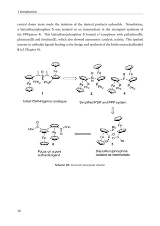
A synthetic approach to a PSiP-Pigiphos analogue 1 was explored. Due to steric hindrance
and synthetic challenges encountered, a double substitution of silicon, by a bulky ferrocenyl
moitety was unsuccessful. Nonetheless, the approach lead to the synthesis of a PSi ligand (2),
which underwent Si–H activation with platinum(0) to yield a hydridoplatinum(II) complex
(cf. Scheme 1).
Fe
Si
S S
P Pt
Ph2 PPh3
H
Fe
Si
SS
PPh2 H
[Pt(PPh3)4]
2
Scheme 1: Si–H activation of PSi ligand 2 with [Pd(PPh3)4].
Due to the problems encountered in the PSiP-Pigiphos synthesis, the synthesis of an alternative
PSiP-pincer like ligand 3, that would form five membered metallacycles upon Si–H activation
was investigated. At the same time, the synthesis of a PPP analogue 4 was attempted, leading
to bissulfoxophosphine 5 as an intermediate compound (cf. Scheme 2).
Fe
Fe
R
E
S S
toltol
O
OECl2RFe
PPh2
S
Ph
O
LDA
3: E = SiH
4: E = P
Fe
Fe
R
E
P P
Ph2Ph2
t-BuLi
ClPPh2
5: E = P, R = Ph
Scheme 2: Attempted synthesis of PSiP ligand 3 and its PPP analogue 4.
The bissulfoxophosphine 5 formed complexes with palladium(II), platinum(II) and
rhodium(I), with the partially characterised rhodium complex showing some activity in the
x](https://image.slidesharecdn.com/17dafaa7-bb25-4952-a328-ce8054639453-151111071008-lva1-app6892/85/eth21627-16-320.jpg)
![Miyaura-Hayashi reaction with low enantiomeric excess (16 %ee) and the structurally charac-
terised palladium complex showing activity in allylic substitution with enantiomeric excess up
to 78 %ee. The synthesis of PSiP ligand 3 and PPP ligand 4 both failed during the coupling
of the ferrocenyl moieties to the central donor atom, most probably due to a oxygen transfer
from the sulfoxide moiety to the eletrophile used in the synthesis.
The synthesis of a bis(ferrocenylsulfoxide) (BiFeSO) 6 was also developed (cf. Scheme 3),
resulting in two compounds that are apparent atropisomers of each other. One of the prod-
ucts 6b was fully characterised, including an X-ray structure. On basis of this data, quantum
chemical calculations were performed to test the atropisomery hypothesis. First the energy
necessary for a configurational change from 6b to 6a was calculated. The values obtained
from that calculation suggest that a configurational change would not take place at rt, there-
fore supporting the concept of two atropisomers. Furthermore, the 1
H-NMR spectra for the
suggested configuration of 6a and the known configuration of 6b were calculated. The results
were in good agreement to the observed 1
H-NMR signals of the ferrocenyl protons of the two
compounds. 6b was reduced to give the bis(ferrocenylsulfide) (BiFeS) 7 (cf. Scheme 3). While
complexation experiments with BiFeSO 6 was unsuccessful, BiFeS 7 seemed to eliminate iso-
butene, when reacted with mercury(II)bromide.
Fe
S t-Bu
O
Li
1. CuCN
2. O2
Fe
Fe
S
S
t-Bu
O
t-Bu
O
NEt3
SiHCl3
Fe
Fe
St-Bu
t-BuS
6 7
Scheme 3: Synthesis of BiFeSO 6 and BiFeS 7.
To complement the primary aims, three side projects were also undertaken during the course
of this work. With the estimation of the fluoride ion affinity of [Ni(II)-(Pigiphos)L]2+
in mind,
the synthesis of [fluoro-Ni(II)-Pigiphos]+
tetrafluoroborate 8 was developed. Due to the prob-
lems encountered in the synthesis of the PSiP ligand 3 and its PPP analogue 4 the synthesis
of bromo-2-(tri-n-butylstannyl)ferrocene 9 was developed with the intention to obtain an ‘in-
ert’ chiral building block, to be able to circumvent problems caused by the sulfoxide moiety. A
third side project lead to the synthesis of (Trifluoromethyl)ferrocenylsulfide 10 using the Togni
acid reagent, with the initial intention to synthesise a less rigid BiFeSO type compound.
xi](https://image.slidesharecdn.com/17dafaa7-bb25-4952-a328-ce8054639453-151111071008-lva1-app6892/85/eth21627-17-320.jpg)
![Zusammenfassung
Die vorliegende Dissertation befasst sich mit der Erforschung neuer chiraler 1,2-
disubstituierter Ferrocenverbindungen mit Bezug auf ihre Darstellung, Eigenschaften und An-
wendungsmöglichkeiten.
Die Darstellung eines PSiP Analogs 1 zu Pigiphos wurde untersucht. Die doppelte Substitution
am Silizium war nicht erfolgreich, da die einzige stabile Ausgangssubstanz für diesen Schritt
eine zu hohe sterische Hinderung aufwies. Stattdessen wurde ein PSi ligand 2 dargestellt,
welcher durch Si–H-Aktivierung mit Platin(0) einen Hydridoplatin(II) Komplex bildet (vgl.
Schema 1).
Fe
Si
S S
P Pt
Ph2 PPh3
H
Fe
Si
SS
PPh2 H
[Pt(PPh3)4]
2
Schema 1: Si–H des PSi-Liganden 2 mit [Pd(PPh3)4].
Da die Darstellung von PSiP-Pigiphos ohne Erfolg blieb, wurde die Synthese eines alternativen
pincerartigen PSiP-Liganden 3 untersucht, welcher durch Si–H-Aktivierung zwei füngliedrige
Metallacyclen bilden würde. Gleichzeitig wurde die Synthese eines PPP-Analogs 4 untersucht,
wobei Bissulfoxophosphin 5 als Zwischenprodukt gewonnen wurde (vgl. Schema 2).
Fe
Fe
R
E
S S
toltol
O
OECl2RFe
PPh2
S
Ph
O
LDA
3: E = SiH
4: E = P
Fe
Fe
R
E
P P
Ph2Ph2
t-BuLi
ClPPh2
5: E = P, R = Ph
Schema 2: Versuchte Darstellung des PSiP-Liganden 3 und seines PPP-Analogs 4.
Bissulfoxophosphin 5 bildet Komplexe mit Palladium(II), Platin(II) und Rhodium(I). Während
xii](https://image.slidesharecdn.com/17dafaa7-bb25-4952-a328-ce8054639453-151111071008-lva1-app6892/85/eth21627-18-320.jpg)
![der nicht charakterisierte Rhodiumkomplex in der Miyaura-Hayashi-Reaktion nur einen gerin-
gen Enantiomerenüberschuss (16 %ee) erzeugte, konnte mit dem Palladiumkomplex in einer
allylischen Substitution ein Enantiomerenüberschuss von bis zu 78 %ee erreicht werden. Die
Synthesen des PSiP- 3 und PPP-Liganden 4 scheiterten beide während der Kupplung der Ferro-
cenyleinheiten an das zentrale Donoratom, wahrscheinlich aufgrund eines Sauerstofftransfers
der Sulfoxidgruppe auf das in der Synthese eingesetzte Elektrophil.
In einem weiteren Schritt wurde die Synthese von Bis(ferrocenylsulfoxide) (BiFeSO) 6 real-
isiert (vgl. Schema 3). Diese lieferte zwei scheinbar atropisomere Produkte. Eines der Pro-
dukte 6b konnte inklusive einer Röntgenstrukturanalyse vollständig charakterisiert werden.
Mit den daraus gewonnenen Daten wurden quantenchemische Berechnungen durchgeführt,
um die Atropisomeriehypothese zu stützen. Zunächst wurde die nötige Energie für einen Kon-
figurationswechsel von 6b zu 6a berechnet. Die daraus berechneten Energien legen nahe,
dass ein Konfigurationswechsel bei Raumtemperatur nicht stattfindet und entsprechend von
Atropisomeren ausgegangen werden kann. Weiter wurden 1
H-NMR Spektren von der für 6a
berechneten Struktur, wie auch der bekannten Konfiguration von 6b berechnet, wobei die
Ergebnisse in Übereinstimmung mit den gemessenen 1
H-NMR Spektren sind. 6b wurde in
einem weiteren Schritt zu Bis(ferrocenylsulfid) (BiFeS) 7 reduziert (vgl. Schema 3). Während
Komplexierungsversuche mit BiFeSO 6 keinen Erfolg brachten, schien BiFeS 7 bei der Umset-
zung mit Quecksilber(II)bromid iso-Buten zu eliminieren.
Fe
S t-Bu
O
Li
1. CuCN
2. O2
Fe
Fe
S
S
t-Bu
O
t-Bu
O
NEt3
SiHCl3
Fe
Fe
St-Bu
t-BuS
6 7
Schema 3: Darstellung von BiFeSO 6 und BiFeS 7.
Zur Ergänzung der Hauptprojekte, wurden drei Nebenprojekte verfolgt. Aus der Ab-
sicht die Fluoridionenaffinität von [Ni(II)-(Pigiphos)L]2+
zu bestimmen, wurde die Syn-
these von [Fluoro-Ni(II)-Pigiphos]+
tetrafluoroborat 8 realisiert. Aufgrund der Probleme bei
der Darstellung des PSiP- 3 und PPP-Liganden 4 wurde die Synthese vom Bromo-2-(tri-n-
butylstannyl)ferrocen 9 entwickelt. Dies in der Absicht einen “inerten”, chiralen Baustein zu
erhalten, um die von der Sulfoxidgruppe verursachten Probleme zu umgehen. In einem drit-
ten Nebenprojekt wurde die Synthese von (Trifluoromethyl)ferrocenylsulfid 10 mit dem Togni-
Säure-Reagenz entwickelt, in der Absicht ein weniger starres BiFeSO-Derivat darzustellen.
xiii](https://image.slidesharecdn.com/17dafaa7-bb25-4952-a328-ce8054639453-151111071008-lva1-app6892/85/eth21627-19-320.jpg)

![1 Introduction
1.1 Ferrocenes
Since its nearly simultaneous discovery by Keally and Pauson[1]
and Miller et al.[2]
in 1951,
ferrocene has been found to be a versatile component of chemical compounds that find ap-
plications in many different chemical areas ranging from homogeneous catalysis to material
sciences and biochemistry.[3–5]
Its stability, which arises from its aromaticity,[6]
paired with
its three dimensional structure[7–9]
makes it an ideal backbone for ligands used in asymmetric
catalysis.[5,10,11]
1.1.1 Nomenclature of enantiomerically pure 1,2-substituted ferrocenes
Unlike the planar benzene homoannular disubstituted ferrocenes bearing to different sub-
stituents do not have a mirror symmetry and are therefore chiral.[12,13]
The absolute configu-
ration of such planar chiral ferrocenes, is assigned following the rules proposed by Schlögel in
1967.[14]
Assignement of the absolute stereochemical configuration of 1,2-disubstituted fer-
rocenes is made by looking along the C5 axis of the ferrocene from the side of the more highly
substituted Cp-ring and arranging the substituents on that ring by their Cahn, Ingold, Prelog
priorities.[15–17]
The absolute configuration (R) or (S) can thus be assigned depending on the
clockwise or counterclockwise, respectively, nature of the resulting sequence of substituents
(cf. Scheme 4). If there are more than three substituents attached to the ring, only the three
with the highest priority are taken into consideration.
Fe
R2
R1
C5 axis
S configuration assuming
R1 has higher priority than R2
(a)
(b)
Fe
Fe
S
S
O
O
(RS,RS,Ra,RFc,RFc)-Bis-[2-(t-butylsulfinyl)ferrocene]
Scheme 4: Assignment of chiral planar configuration following Schlögel’s rule.
1](https://image.slidesharecdn.com/17dafaa7-bb25-4952-a328-ce8054639453-151111071008-lva1-app6892/85/eth21627-21-320.jpg)
![1 Introduction
In order to distinguish planar chirality from other chirality units, such as central or axial chi-
rality, present in a molecule a "p" subscript is often used next to the assigned configuration.
The use of an "Fc" subscript has also become more common in ferrocene chemistry, in order
to avoid confusion with stereogenic phosphorus atoms in molecules, for which a "P" subscript
is often used. Conventionally, chiral elements have the following priorities: central > axial >
planar (cf. Scheme 4).[18]
1.1.2 Synthetic routes towards enantiomerically pure 1,2-substituted ferrocenes
Various methods have been developed to introduce planar chirality to ferrocenes, which, in
principle, can be divided into three types: A) diastereoselective directed ortho-metalation,
B) enantioselective directed ortho-metalation and C) resolution of racemic planar chiral
ferrocenes (cf. Scheme 5).[18]
In case A, a chiral auxiliary is used as a chiral directing metalation group (DMG). The
auxiliary has the ability to coordinate organolithium or lithium amide species and, through
the complex induced proximity effect (CIPE),[19]
is therefore able to diastereoselectively
deprotonate one ortho position on the ferrocene. The resulting lithium ferrocene can then be
quenched with an electrophile to yield a planar chiral 1,2-disubstituted ferrocene. In order
to introduce planar chirality through CIPE, the auxiliaries feature nitrogen or oxygen lone
pair coordinating sites. In contrast, in case B, the DMG is achiral and the method relies on
chiral lithiation agents to differentiate between the prochiral ortho positions. For method C,
on the other hand, the racemate is first synthesised and later kinetically resolved, either by
enzymatic or non-enzymatic kinetic resolution.
As type A is the most developed of the methods discussed and has also been the basis for the
work described in this thesis, deeper discussion of work done using this method will follow,
while methods B and C will be discussed briefly in this section.
Early work based on enantioselective directed ortho-metalation (method B) used (–)-sparteine
on isopropylferrocene resulting in slight enantiomeric excess of 3 % ee.[20]
Work done by
Price et al. using a chiral lithium alkyl amide on ferrocenyldiphenylphosphinoxide[21]
resulted
in only moderate enantiomeric excesses (54 % ee).[21]
The first satisfactory results based on
method B were reported almost concurrently by Tsukazaki et al. by using (–)-sparteine for the
n-BuLi mediated lithiation of N,N-diisopropyl ferrocenecarboxamide with an enantiomeric
excess of up to 99 % ee (cf. Scheme 6).[22]
In addition to further reports of (–)-sparteine
mediated ortho-lithiation,[23,24]
more recent work by Dixon et al. also shows the effective use
of sparteine surrogates for enantioselective ortho-lithation.[25]
2](https://image.slidesharecdn.com/17dafaa7-bb25-4952-a328-ce8054639453-151111071008-lva1-app6892/85/eth21627-22-320.jpg)
![1.1 Ferrocenes
Fe
DMG
A diastereoselective directed ortho-metallation
RLi
Fe
DMG
Li E+
Fe
DMG
Fe
DMG
E
E
or
enantiomerically pure
Fe
DMG
B enantioselective directed ortho-metallation
RLi / chiral diamine
Fe
DMG
Li E+
Fe
DMG
Fe
DMG
E
E
or
achiral
chiral lithium amide
Fe
R2
C kinetic resolution
kinetic resolution
racemate
R1
Fe
R1
R2
+
Fe
R2
A
Fe
R1
R2
+
Fe
R2
R1
Fe
R1
A
+
or
Scheme 5: Three principle methods to introduce planar chirality to ferrocenes.[18]
Fe O
N
i-Pr
i-Pr
1. 1.2 equiv n-BuLi / (–)-sparteine
Et2O, –78°C
2. Ph2CO
Fe O
N
i-Pr
i-Pr
CPh2
OH
91% yield
99%ee
Scheme 6: An example for method B as reported by Tsukazaki et al.[22]
3](https://image.slidesharecdn.com/17dafaa7-bb25-4952-a328-ce8054639453-151111071008-lva1-app6892/85/eth21627-23-320.jpg)
![1 Introduction
The first use of kinetic resolution on planar chiral 1,2-disubstituted ferrocenes was Horeau’s
method[26–28]
as applied by Falk and Schlögl in order to determine the absolute config-
uration of (+)-1,2-(α-ketotetramethylene)-ferrocene,[29]
which they isolated by reaction
with (–)-menthylhydrazide followed by multiple recrystallisations.[30]
However, Horeau’s
method represents an analytical tool, rather than a useful synthetic method, as racemic
phenyl butyric acid is reacted with an enantiopure substance in order to determine the
enantiomeric excess of the unreacted phenyl butyric acid. Although stochiometric kinetic
resolution of planar chiral ferrocenes is still a topic of current investigation,[31]
a more elegant
method of kinetic resolution of planar chiral ferrocenes for synthetic purposes is of a catalytic
fashion. One way to achieve this is through enzyme-catalysed asymmetric reactions that
have a long history in a variety of applications.[32]
First investigations of this method were
reported in the late 1980s using baker’s yeast, while later work focused on the esterification
of 1,2-disubstituted ferrocenyl alcohols by lipase (cf. Scheme 7), giving up to 95 % ee at
32 % yield in case for Candida cylindracea lipase[33]
(for a list of examples of enzymatic kinetic
resolution see Deng et al.[18]
and references therein).
Fe
OH
CCL, vinyl acetate
N
Fe
N
OH
+ Fe
OH
N
Fe
N
OAc
+
32% yield
95%ee
42% yield
92%eeCCL = Candida Cylindracea Lipase
Scheme 7: Example for enzymatic kinetic resolution as reported by Lambusta et al.[33]
A potential alternative to the enzymatic resolution is represented by the use of asymmetric
catalysis for kinetic resolution. This method was first applied in 2006 by Bueno et al. using
Sharpless asymmetric dihydroxylation.[34]
In the same year, Ogasawara et al. reported a
kinetic resolution based on asymmetric ring closing metathesis (cf. Scheme 8), which became
a matter of further investigation in his group.[35–37]
4](https://image.slidesharecdn.com/17dafaa7-bb25-4952-a328-ce8054639453-151111071008-lva1-app6892/85/eth21627-24-320.jpg)
![1.1 Ferrocenes
Fe
(R)-Mo cat.
0.005 mol/l in benzene
50°C, 24h
t-But-Bu
Fe
t-But-Bu
Fe
t-But-Bu
+
+
Fe
t-Bu
t-Bu
2
47% yield
95%ee
46% yield
96%ee
3% yield(R)-Mo cat.
t-Bu
t-Bu
O
OMo
N
i-Pr
i-Pr
Me
Ph
Me
(rac)
Scheme 8: Asymmetric ring closing metathesis as reported by Ogasawara et al.[38]
1.1.2.1 Ugi-approach Although the first synthesis and isolation of (rac)-[1-
(dimethylamino)ethyl]ferrocene 11 was already reported in 1957 by Hauser and Lindsay,[39]
no special interest was given to this material until resolution with (R)-(+)-tartaric acid as
well as its use in diastereoselective ortho lithiation was reported by Ugi and co-workers.[40,41]
Due to the tertiary amine 11’s importance to the synthesis of chiral ferrocene derivatives, it
has become known under the trivial name Ugi’s amine.
Synthesis of Ugi’s amine. Many attempts towards the improvement of the synthesis of
optically pure Ugi’s amine have been reported,[42–48]
among which enzymatic methods[43,48]
as well as Corey-Bakshi-Shibata reduction[44–46]
proved to be applicable on a multi-kilogram
scale.[46,48]
However, the most widely used synthetic route is based on the synthetic route,
improved to limit the formation of vinyl ferrocene in the alcohol activation step, reported
by Ugi’s and co-workers in 1972[42,49]
(cf. Scheme 9). Resolution is still performed using
(R)-(+)-tartaric acid to crystalise the (S)-11 tartrate from methanol. The (R)-11 tartrate is
then recovered through evaporation of the mother liquor and recrystallisation from aqueous
acetone.[40,49]
5](https://image.slidesharecdn.com/17dafaa7-bb25-4952-a328-ce8054639453-151111071008-lva1-app6892/85/eth21627-25-320.jpg)
![1 Introduction
Fe Fe
CH3COCl
AlCl3, DCM
O
LiAlH4
benzene
Fe
OH
HOAc
benzene
Fe
OAc
HNMe2
MeOH
Fe
NMe2
resolution
Fe
NMe2
Fe
NMe2
(S)-11 (R)-11(rac)-11
+
Scheme 9: Synthesis of Ugi’s amine.[40,49]
Use in synthesis of 1,2-disubstituted ferrocenes. Ugi and co-workers showed, that
treatment of (R)-11 with n-BuLi leads to a directed ortho-lithiation.[40,41]
This is due to the
interaction with the nitrogen lone-pair, which stabilises the lithium ion at one of the ortho
positions more favourably than the other. Inspection of the two possible diastereomers of
lithiated (R)-Ugi’s amine 12 reveals that (R,SFc)-12 is disfavoured due to the steric interaction
of the methyl group with the Cp -ring, whereas the (R,RFc)-12 diastereomer can be formed
without any steric hindrance. This interaction results in a diastereomeric ratio up to 96:4 dr
for the final products, as demonstrated by quenching with a variety of electrophiles[40]
(cf.
Scheme 10).
Fe
NMe2
(R)-12
Li
Fe
(S)-12
Li
NMe2 E+
Fe
NMe2
E
up to 96:4drsteric repulsion
Scheme 10: Selective ortho lithiation of Ugi’s amine.[40,41]
As the resulting products are diastereomers, separation of the major and minor product can
usually by achieved by flash column chromatography or crystallisation yielding the major di-
6](https://image.slidesharecdn.com/17dafaa7-bb25-4952-a328-ce8054639453-151111071008-lva1-app6892/85/eth21627-26-320.jpg)
![1.1 Ferrocenes
astereomer in high purity. In a further step, the dimethylamino group of the ortho-substituted
Ugi’s amine 13 can be substituted by convertion to a leaving group, e.g. under acidic
conditions or by methylation of the amine. Ugi and co-workers reported that substitution of
the amine takes place with full retention.[50]
They stated that the reaction seems to follow
a non-classical SN 1-mechanism, in which the N–C bond is cleaved simultaneously with the
Fe–C bond to form a carbenium ion. As a matter of fact, the stabilising effect of ferrocene
on adjacent carbenium ions was already known and had been thoroughly investigated at the
time,[51,52]
leading to the conclusion that there is a significant interaction between iron and
the double bond formed during an elimination process, resulting in an 18 e−
configuration
of the formal Fe(III) centre.[53,54]
The masked carbenium ion 14 is then attacked in an exo
fashion by a nucleophile, resulting in retention of the configuration (cf. Scheme 11).
Fe
LG: e.g. HNMe2
+,NMe3
+,OAc
LG
H
Me
Fe+
H
Me
14
Nu-
Fe
Nu
H
Me
Scheme 11: Non-classical SN 1-mechanism for the substitution at the "benzylic" carbon.[53,54]
Due to these properties, Ugi’s amine is used a the starting material for a wide variety of
ferrocene-based ligands with central and planar chirality having applications in asymmetric
catalysis.[55–68]
Some of these ligands can be synthesised in a simple two step reaction from
Ugi’s amine, as in the case of Josiphos (cf. Scheme 12).
Fe
NMe2
Fe
NMe2
Fe
PCy2
PPh2 PPh2
(R)-11 (R,SFc)-PPFA (R,SFc)-Josiphos
1. n-BuLi,
THF, –78°C
2. ClPPh2
HPCy2
AcOH, 80°C
Scheme 12: Synthesis of Josiphos.
7](https://image.slidesharecdn.com/17dafaa7-bb25-4952-a328-ce8054639453-151111071008-lva1-app6892/85/eth21627-27-320.jpg)
![1 Introduction
1.1.2.2 Sulfoxide approach A more recent approach towards the synthesis of chiral 1,2-
disubstituted ferrocenes is based on chiral ferrocenyl sulfoxides. Their use in diastereoselec-
tive ortho-lithiation was first reported in 1993 by Kagan and co-workers.[69]
The chiral ferro-
cenyl sulfoxides used for the directed ortho-lithiation are readily accessible through enantio-
selective oxidation of the sulfide[69–71]
or by nucleophilic attack of lithioferrocene on optically
pure sulfinates[72–75]
or thiosulfinates[76–79]
(cf. Scheme 13).
Fe
LiO
S
p-tol
O
S
S
O
Fe Fe
S Sp-tol
O O
Fe
S 1 equiv cumene hydroperoxide
1 equiv Ti(Oi-Pr)4
2 equiv (S,S)-diethyl tartrate
1 equiv H2O
Fe
S
O
Scheme 13: Synthetic routes to chiral sulfoxides.[69–79]
Use in synthesis of 1,2-disubstituted ferrocenes. Ortho-lithiation of ferrocenyl sulfoxides
is usually effected by addition of n-BuLi or LDA, depending on the other sulfoxide substituent
(cf. Scheme 14). Like the nitrogen lone-pair in the case of Ugi’s amine (vide supra), the oxygen
lone-pair of the sulfoxide facilitates ortho-lithiation, favouring the lithiated diastereomer with
the sulfoxide substituent anti to the ferrocene. Therefore, the two commonly used ferrocenyl
sulfoxides (RS)-t-butylferrocenylsulfoxide 15 and (SS)-p-tolylferrocenylsulfoxide 16 give
1,2-disubstituted ferrocenes with opposite planar chirality (cf. Scheme 14).
An advantage of p-tolylsulfoxide 16 over t-butyl sulfoxide 15 is the possibility to replace the
8](https://image.slidesharecdn.com/17dafaa7-bb25-4952-a328-ce8054639453-151111071008-lva1-app6892/85/eth21627-28-320.jpg)
![1.1 Ferrocenes
Fe
S p-tol
O
LDA
Fe
S
p-tolOLi
TMSCl
Fe
S p-tol
OTMS
Fe
S t-Bu
O
Fe
S
t-Bu
O
MeI
Fe
S
t-Bu
O
Li Men-BuLi
Scheme 14: Diastereoselective ortho lithiation of sulfoxides.[75,77]
sulfoxide by another substituent through attack with either t-BuLi[75]
or PhLi[80]
forming
the corresponding sulfoxide and lithioferrocene species. Subsequent quenching of the
lithioferrocene with an electrophile gives access to a large variety of ligands[81]
(cf. Scheme
15).
Fe
S p-tol
OR
t-BuLi
t-Bu
S
p-tol
O
Fe
R
Li
E+
Fe
R
E
Scheme 15: Substitution of p-tolyl sulfoxide.[75]
1.1.2.3 Chiral acetal approach Another approach towards enantiopure 1,2-disubstituted
ferrocenes developed in Kagan’s group utilises the chiral acetal 17 and was reported by Riant et
al. in 1993.[82]
The methoxymethyl dioxane 17 is readily accessible from ferrocene by a three
step synthesis with an overall yield of 82 % (cf. Scheme 16). The (S)-(–)-1,2,4-butanetriol
needed for the synthesis of hydroxymethyl acetal 18 can be readily obtained by reduction of
(S)-(–)-malic acid with borane.[83]
Therefore, the approach is also economically viable. The
9](https://image.slidesharecdn.com/17dafaa7-bb25-4952-a328-ce8054639453-151111071008-lva1-app6892/85/eth21627-29-320.jpg)
![1 Introduction
directing effect in ortho lithiation arises from the stabilising effect of the methoxy group and
one of the dioxane oxygen atoms, which chelate the lithium at the ortho position that leads to
Fe
O
(MeO)3CH
p-tolyl sulfonic acid
80°C
Fe
O
O (S)-(–)-1,2,4-butanetriol
camphor sulfonic acid
CHCl3, 4Å, rt
Fe
H
OO
OH
18, 85%
1. NaH, THF, 0°C
2. MeI Fe
H
OO
O
17, 97%
Scheme 16: synthesis of the chiral acetal 17.[84]
the most favourable chelation ring, resulting in the (S)-lithioferrocene 19 yielding the product
in a diastereomeric ratio of 99:1 dr[82]
(cf. Scheme 17). Most probably, the orientation of the
oxygen, which is not involved in the lithium chelation towards the iron moiety may have a
major impact on diastereoselectivity. In the case of (R)-19 this atom is positioned endo with
respect to the iron centre, whereas in (S)-19 it is oriented exo.[84]
It has also been shown, that
the directing effect is of kinetic origin, since the diastereomeric excess decreases significantly
if the reaction temperature is raised, with 95:5 dr at 0 ◦
C.[82]
The directing acetal can be removed by hydrolysis after planar chirality has been introduced.
The resulting enantiopure 2-substituted formylferrocene has proven useful for synthesis of a
large variety of chiral ferrocenyl compounds (cf. Scheme 18).
1.1.2.4 Oxazolines Enantiomerically pure ferrocenyl oxazolines are readily synthesised
from ferrocenylacyl chloride and the corresponding amino alcohol (cf. Scheme 19). The enan-
tiomerically pure amino alcohols can be generated through the reduction of amino acids,[85,86]
whereby a large variety of chiral oxazolines are accessible.
10](https://image.slidesharecdn.com/17dafaa7-bb25-4952-a328-ce8054639453-151111071008-lva1-app6892/85/eth21627-30-320.jpg)
![1.1 Ferrocenes
H
Fe
H
OO
O
t-BuLi
Fe
O
O
OLi
Fe O
O
OLi
H
(S)-19
(R)-19
E+
Fe
H
OO
O
E
99:1dr
–78°C
Scheme 17: Diastereoselective ortho-lithiation of acetal 17.[82,84]
Fe Fe
P
Ph
Fe
Fe
N N
H
Fe
Fe
OH
HO
Scheme 18: Ligands synthesised by following the acetal approach.[87–90]
Directed ortho-lithiation of enantiopure ferrocenyl oxazolines has been performed by the
treatement of the oxazoline with n-BuLi or s-BuLi in ethers at –78 ◦
C giving a diastereomeric
excess up to 97:3 dr.[91–95]
An alternative experimental procedure using hexanes as solvent
and TMEDA gave an diastereomeric excess of >99:1 dr. This method was designed by Sam-
makia et al. in order to test their hypothesis for directed ortho lithiation.[93,94]
They proposed
that control of diastereoselectivity is derived from the steric interaction of the bulky group on
the oxazoline with the butyl group of the butyllithium, rather than the interaction with the
ferrocene. Therefore the stereo information would be imparted in the transition state of the
deprotonation of the ortho position (cf. Scheme 20). However, other factors that may influ-
ence the diastereoselectivity exist and they should still be taken into consideration.
11](https://image.slidesharecdn.com/17dafaa7-bb25-4952-a328-ce8054639453-151111071008-lva1-app6892/85/eth21627-31-320.jpg)
![1 Introduction
Fe
Cl
O
OHH2N
R
1. , Et3N, CH2Cl2
2. a, b or c
a: TsCl, Et3N, cat. DMAP, CH2Cl2
b: SOCl2, 20% K2CO3 (aq.)
c: PPh3, CCl4, NEt3, CH3CN
Fe
O
N
R
Scheme 19: Synthesis of enantiomerically pure ferrocenyl oxazolines.[92,93,95]
Fe
O
N
R
BuLi
Fe
H
Li Bu
N
O
R
Fe
H
LiBu
N
O
R steric repulsion
major minor
Fe
O
N
R
Fe
O
N
R
E+
E
E
major minor
Scheme 20: Diastereoselective ortho lithiation of ferrocenyl oxazolines.[93,94]
Hydrolysis of the oxazoline could be considered as a feasible method to replace the oxazoline
by another functionality. However, the donor features of the oxazoline make it useful as coor-
dination site for complexation and thus render an exchange unnecessary for the synthesis of
chiral ligands. This is one of the major advantages of the oxazoline approach,[18]
as it gives ac-
cess to asymmetric bidentate ligands in only a single reaction step, complementing the already
large variety of oxazoline ligands[96,97]
with their ferrocene derivatives.
12](https://image.slidesharecdn.com/17dafaa7-bb25-4952-a328-ce8054639453-151111071008-lva1-app6892/85/eth21627-32-320.jpg)
![1.1 Ferrocenes
1.1.2.5 Directing groups containing phosphorus A variety of aryl phosphine deriva-
tives have been shown to have an ortho directing effect upon metallation.[98–103]
The
diastereoselective ortho metallation utilising chiral ferrocenyl phosphine derivatives seems
somewhat obvious. However, only a few successful examples are known. One of these is the
ortho-magnesiation reported by Nettekoven et al.[104–106]
(cf. Scheme 21). A diastereoselective
excess of 97:3 dr in quantitative yield was achieved, using iodine as the electrophile.
Fe
P
O
R
Fe
Mg
O
P
Fe
Mg O
P
major minorsterical repulsion
(i-Pr)2NMgBr
I2
Fe
P
O
R
I
97:3dr
R:
Scheme 21: Diastereoselective ortho magnesation reprted by Nettekoven et al.
Another successful example is that of the oxazaphospholidine-oxide reported by Xiao and
co-workers,[107–109]
which undergoes diastereoselective ortho-lithiation with t-BuLi, giving
a diasteremeric excess of >99:1 dr in yields varying between 45 – 95 %, depending on the
electrophile. They also discovered, that the yield decreases significantly with the use of n-BuLi
as lithiating agent, due to reaction with the phosphorus moiety (cf. Scheme 22),[107]
which is
a general problem in directed ortho lithiation of phosphine derivatives.[103]
An example using
a P(III) instead of a P(V) phosphorus derivative was patented by Pfaltz et al.,[110]
who used a
borane protected phosphine bearing chiral amidites to yield 1,2-disubstituted ferrocenes with
99:1 dr (cf. Scheme 23).
13](https://image.slidesharecdn.com/17dafaa7-bb25-4952-a328-ce8054639453-151111071008-lva1-app6892/85/eth21627-33-320.jpg)
![1 Introduction
Fe
P
O
O
N
Ph
1. t-BuLi, –78°C
2. E(X)
E(X) = Me(I), I(I), TMS(Cl), TES(Cl), Ph2CO, B(OMe)3, PR2(Cl)
Fe
P
O
O
N
PhE
>99:1dr
Fe
P
O
O
N
Ph
1. n-BuLi, –78°C
2. MeI
Fe
P
O
O
N
PhMe
>99:1dr, 33%
Fe
P
O
n-Bu
N
MeO
Ph
50%
Scheme 22: Diastereoselective ortho lithiation of oxazaphospholidine-oxide as reported by Xiao and
co-workers.[107–109]
Fe
P
BH3
N
N
OMe
OMe
1. s-BuLi, Et2O, –78°C
2. E(X)
Fe
P
BH3
N
N
OMe
OMe
E
E(X) = TMS(Cl), PPh2(Cl), Br(CF2CF2Br)
Scheme 23: Diastereoselective ortho lithiation as reported by Pfaltz et al.[110]
14](https://image.slidesharecdn.com/17dafaa7-bb25-4952-a328-ce8054639453-151111071008-lva1-app6892/85/eth21627-34-320.jpg)
![2 Synthetic approaches towards PSiP-Pigiphos
2.1 Introduction
Ferrocenyl-based ligands developed for application in asymmetric catalysis have a long history
within the Togni group. Besides the well-known bidentate phosphine ligand Josiphos, a variety
of different ferrocene-based ligands (cf. Scheme 26) have been created and studied by former
and current members of the Togni group. Among these is the tridentate phosphine ligand
Pigiphos, which was first synthesised by Pierluigi Barbaro[60]
following a straightforward two
step synthesis starting from commercially available Ugi’s amine (cf. Scheme 27).
Fe
N
N
R'
R''
PPh2
Fe
P
Fe
PPh2 Ph2P
Cy
Fe
Fe
N N
H
Fe
PCy2
PPh2
Fe
FeP
Cy
Josiphos
Pigiphos
Scheme 26: Selection of ferrocene based ligands synthesised in the Togni group.
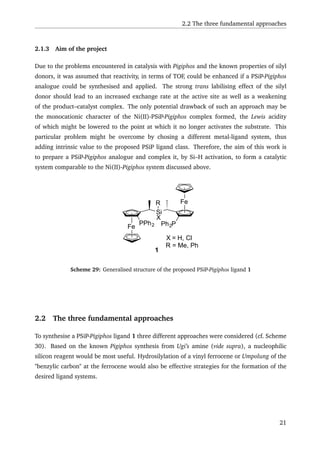
Pigiphos readily forms complexes with a wide variety of late transition metals,[60,112–115]
whereby the first reported asymmetric catalysis with the ligand used a ruthenium(II)-Pigiphos
complex for transfer hydrogenation of acetophenone.[112]
Special interest has been taken in
the dicationic nickel(II)-Pigiphos complex, which was first synthesised and used for asymmet-
ric acetalisation by Barbaro.[113]
As a chiral lewis acid it was also used as a catalyst for hy-
droamination,[111,116]
hydrophosphination,[117,118]
Nazarov-cyclisation[119,120]
and 1,3-dipolar
17](https://image.slidesharecdn.com/17dafaa7-bb25-4952-a328-ce8054639453-151111071008-lva1-app6892/85/eth21627-37-320.jpg)
![2 Synthetic approaches towards PSiP-Pigiphos
Fe
N
1. t-BuLi
2. ClPPh2
Et2O, -78 °C Fe
N
PPh2
CyPH2, TFA
AcOH, 80 °C
Fe
P
Fe
PPh2 Ph2P
Cy
Scheme 27: Two step synthesis of (R)-(SFc)-Pigiphos derivatives starting from Ugi’s amine.[111]
O
CO2R2
R3Ph
R1
20a-h 21a-h
i) [Ni(II)-Pigiphos](ClO4)2
in situ
THF, rt
ii) CH2Cl2, rt
O
R1
Ph
CO2R2
R3
Compound R1
R2
R3
Yield (%) ee (%)
21a Me Et TMPa
84 86
21b Ph Et TMPa
85 87
21c Me Et PMPb
32 71
21d Ph Et PMPb
96 83
21e Me Pr TMPa
80 82
21f Ph Pr TMPa
82 88
21g Me Bn TMPa
58 45
21h Me Npc
TMPa
no reaction n.a.
Reaction times for full conversion are 6 – 8 d for substrates having R3
= TMP
and 9 – 15 d for R3
= PMP. a
TMP = 2,4,6-trimethoxyphenyl. b
PMP = 4-
methoxyphenyl. c
Np = 1-naphtyl.
Table 1: Ni-catalysed Nazarov cyclisations of various dialkenyl ketones[120]
cycloaddition reactions. Despite this variety of applications of the dicationic Ni(II)-Pigiphos
complex the strong binding of the dicationic Ni(II)-Pigiphos complex to coordinating solvents
is a considerable problem, that leads to catalyst poisoning and therefore low TON. Similarly,
in case of the Nazarov-cyclisation the strong binding of Ni(II)-Pigiphos to the product in the
catalytic cycle , leads to low TON, as well as long reaction times due to low TOF (cf. Table 1).
18](https://image.slidesharecdn.com/17dafaa7-bb25-4952-a328-ce8054639453-151111071008-lva1-app6892/85/eth21627-38-320.jpg)
![2.1 Introduction
2.1.1 Attempts to improve the Ni(II)-Pigiphos system
In order to overcome the above mentioned activity problems, the introduction of an N-
heterocyclic carbene (NHC) moiety as a replacement for the central phosphorus donor site
in the Ni(II)-Pigiphos system was undertaken in our group. NHCs display similar bonding
properties to trialkylphosphines,[121,122]
but with the benefit of being much stronger σ-donors
in most cases. Although the synthesis of the NHC bearing Pigiphos analogue 22 has been
performed successfully (cf. Scheme 28),[123]
it turned out to have major disadvantages due
to the flexibility of the system caused by the additional bridging carbon atoms between the
ferrocene and the carbene moiety. Not only were lower enantiomeric excesses observed,
but in most cases no advantages over the Pigiphos catalytic system could be discerned. In
addition to the above mentioned conformational flexibility, the NHC-Pigiphos derivative
also showed relatively weak coordination of the NHC moiety to metal centres. For example,
an extraordinarily long NHC-Pd bond of 2.040(12) Å[123]
is observed in the Pd(II) iodo
complex of this ligand. This unusually long distance between the donor ligand and metal is
most likely a result of disfavoured seven membered metallacycles formed by coordination
of the phosphine groups. As a consequence of these results and observations, an alternative
modification of Pigiphos was thought to be necessary.
Fe
NMe2 1. t-BuLi, Et2O
2. ClPPh2
3. AcOAc, 2-5 h,
100 °C
Fe
OAc
PPh2
1. Imidazole,
AcCN/H2O
2. NaI, EtOH,
3 h, rt Fe
Fe
N N
HPPh2 Ph2P
22
Scheme 28: Synthesis of the NHC-Pigiphos analogue 22.
19](https://image.slidesharecdn.com/17dafaa7-bb25-4952-a328-ce8054639453-151111071008-lva1-app6892/85/eth21627-39-320.jpg)
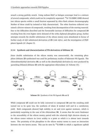
![2 Synthetic approaches towards PSiP-Pigiphos
2.1.2 Silyl ligands
Although Wilkinson reported the first transition metal silyl derivative as early as 1956,[124]
the
developement of the field was initially slow.[125]
Only after the discovery of transition-metal-
catalysed hydrosilylation of alkenes[126]
and the importance of the Si–H activation by oxidative
addition behind it,[127]
did interest in the area start to grow. Silyl ligands are particularly
strong σ-donors and have been shown to have a strong trans influence. X-ray crystallographic
analyses show Pt–Cl bond lengths trans to the silyl donor are up to 0.161 Å longer than those
in PtCl2−
4
with Pt–Cl bond lengths of 2.465 (2) Å in case of the triphenylsilyl platinum com-
plex 23 (cf. Figure 1).[128]
This fact, together with the low frequency IR signals for ν(Pt–Cl)
at 239 cm−1[129]
observed are clear indicators of the strong trans influence of silicon donor
ligands.
PtCl
Si
P2
P1
Figure 1: X-ray structure of the triphenylsilyl platinum complex 23.[128]
Currently, there is a special interest in incorporating silyl donors into ancillary ligand frame-
works. In such a framework, the strong trans labilising σ-donor properties of the silyl donor
can be fully utilised.[130]
Such ligands form coordinatively unsaturated complexes and have
been purported to show enhanced reactivities.[131,132]
Many complexes of this type have been
reported and some have shown interesting catalytic activity.[132–144]
There are a variety of
methods to form Si–M bonds in a complex. Among the most common is Si–H activation. As
Si–H bonds are known to be more reactive toward oxidative addition than other Si–X bonds,
this represents one of the most viable paths to Si–M complexes. Methods using transition
metal anions or silyl anions have also been reported.[125]
20](https://image.slidesharecdn.com/17dafaa7-bb25-4952-a328-ce8054639453-151111071008-lva1-app6892/85/eth21627-40-320.jpg)
![2 Synthetic approaches towards PSiP-Pigiphos
Fe
Si
X
Fe
PPh2 Ph2P
R
Fe
PPh2
Fe
PPh2
Fe
PPh2
LG
M
+ RSiH2X + RSiM2X
+ RSiCl2X
Hydrosilylation route Nucleophilic silicon route
Umpolung route
1
Scheme 30: Three fundamental retrosynthetic routes to synthesise PSiP-Pigiphos 1
2.2.1 Nucleophilic silicon
The simplest form of a nucleophilic silane moiety, is the analogue of the carbanion, which
here may be referred to as silicon anions for simplicity. As a matter of fact, silicon anions
have been the subject of investigation for the better part of the past century.[145–148]
Usu-
ally, symmetrically substituted disilanes are treated with alkali metals in ether solution to
give alkali silicides. Metallation of halosilanes has also been reported, whereby a disilane is
formed in a Würtz-coupling-type reaction which is then cleaved by the alkali metal. Finally,
deprotonation of certain silanes by potassium hydride has been observed as well.[149]
One
of the most common silyllithium compounds is triphenylsilyllithium, the reaction of which
with diphenylphosphinoacetylferrocene could provide a starting point for PSiP-Pigiphos, since
the phenyl substituents on silicon may be readily removed with triflic acid.[150]
The resulting
silyl triflate may be lithiated a second time leading to the desired product in a multistep syn-
22](https://image.slidesharecdn.com/17dafaa7-bb25-4952-a328-ce8054639453-151111071008-lva1-app6892/85/eth21627-42-320.jpg)
![2.2 The three fundamental approaches
thesis (cf. Scheme 31). However, the harsh reaction conditions and multistep synthetic route
render such an approach a significant challenge.
Fe
Si
X
Fe
PPh2 Ph2P
R
Fe
PPh2
X LiSiPh3
Fe
PPh2
SiPh3
Fe
PPh2
SiPh2
HOTf
Lithiation
OTf
1
Scheme 31: Theoretical multistep synthetic route towards PSiP-Pigiphos using silyl lithium.
Rhodium(I) or copper(I) activated Si–B bonds may also act as silyl nucleophiles. Nucleophilic
silicon compounds of this nature form the corresponding silicon cuprate or rhodate in cat-
alytic quantities. To date, these metal-silicon compounds have been reacted with electrophiles
such as aldehydes or α,β-unsaturated carbonyls.[151,152]
This kind of reaction has only been
reported for monoborylsilanes. Therefore, this approach to the synthesis of PSiP-Pigiphos,
requiring boryl silanes, is also synthetically complicated, since the boryl silanes are synthe-
sised from corresponding chlorosilanes in a multistep process, hence resulting in a complex,
multistep synthesis of the desired product.
2.2.2 The hydrosilylation route
Since the first use of the term "catalytic hydrosilylation" by Ojima et al.[153]
many new cat-
alytic systems have been reported,[154,155]
and the method has been developed into one of the
most important uses of homogeneous platinum catalysis, second in importance only to the vul-
canisation of silicone rubber.[156]
Considering the ready accessibility of vinyl ferrocenes from
Ugi’s amine[157]
hydroslilylation may be a feasible synthetic strategy for a PSiP backbone. The
only foreseeable pitfall of this method may arise from anti-Markovnikov addition to the vinyl
group, which would lead to a C2 tether instead of a C1 tether between the silicon moiety and
the ferrocenyl unit.
23](https://image.slidesharecdn.com/17dafaa7-bb25-4952-a328-ce8054639453-151111071008-lva1-app6892/85/eth21627-43-320.jpg)
![2 Synthetic approaches towards PSiP-Pigiphos
2.2.3 The Umpolung
As chlorosilanes are not only good electrophiles but are also commercially available in many
varieties, an Umpolung of the benzylic position of a ferrocene derivative might be a straight-
forward path towards the synthesis of a PSiP-Pigiphos. Different approaches towards such
an Umpolung may be considered. Although Gmelin reports the existence of ferrocenyl-
(chlorozirconocenyl)-methane,[158]
the original literature[?,159]
shows that, as one would ex-
pect, the hydrozirconation of formyl ferrocene using Schwartz’ reagent results in the zir-
conocene bound to oxygen, with the hydrogen adding to the adjacent carbon. However,
such an approach could be considered, as well as the potential hydrozirconation of a vinyl
ferrocene, despite the potential for the formation of a C2 tethered system.
A further approach would be a Corey-Seebach-Umpolung[160]
, which is a simple method for
the synthesis of acylsilanes.[161]
This method has already been demonstrated for formyl fer-
rocene by Reuter et al.[162]
By using an enantiomerically pure formyl ferrocenyl phosphine,
this seems a tantalisingly elegant approach. Kondo et al. described a synthetic route to fer-
rocenylmethyllithium in the early 1970s, through reductive lithiation of ferrocenylmethyl-
methoxide.[163,164]
Two decades later Knochel and co-workers claimed a similar approach to
stable α-ferrocenyllithium derivatives starting from α-thioethers, -ethers and -amines.[165]
In
this case, the approach via the amine is of interest since Ugi’s amine may be used to introduce
planar chirality (cf. Paragraph 1.1.2.1).
2.3 Synthetic Results
The different approaches towards the synthesis of PSiP-Pigiphos mentioned in the introduction
of this chapter were investigated in parallel to determine, as quickly as possible, which would
be the most feasible. Application of a nucleophilic source of silicon was ruled out during
preliminary investigations, due to the foreseen difficulties concerning harsh reaction condi-
tions combined with a long multistep reaction path (vide supra). The respective reaction paths
and the associated difficulties are discussed in more detail to clarify the choice of synthetic
approach.
2.3.1 Hydrosilylation attempts
Although hydrosilylation is a widely used method for introduction of silicon or a hydroxy group
into a molecule, its use on vinylferrocenes is largely unkown. The work by Morán et al. on oc-
takis(dimethylsiloxy)octasilsesquioxanes[166]
is often cited, as is Losada’s work on ferrocenyl
24](https://image.slidesharecdn.com/17dafaa7-bb25-4952-a328-ce8054639453-151111071008-lva1-app6892/85/eth21627-44-320.jpg)
![2.3 Synthetic Results
functionalised silane based dendrimers.[167,168]
Both use Karstedt’s catalyst for the reaction
with tertiary silanes. Regrettably, their catalytic system failed to yield hydrosilylation products
when chlorophenylsilane or chloromethylsilane were used in combination with vinylferrocene
or (diphenylphosphino)vinylferrocene.
Other attempts using chloroplatinic acid, a known catalyst for the hydrosilylation of styrenes
by chlorosilanes,[169,170]
did not result in the desired product, regardless of substrate. Due to
the failure of these experiments to produce the target compounds and the fact that hydrosi-
lylation should lead to the less favoured C2-tethered product, efforts along this route were
ceased.
2.3.2 Attempts towards an Umpolung
An Umpolung strategy by reductive lithiation as described by Knochel and co-workers[165]
was
one of the first methods for the generation of silylated ferrocenyl materials pursued in this
work. Despite several attempts to follow this reaction protocol, the results proved unrepro-
ducible. A hydrozirconation approach, as described by Etiévant,[159,171]
was performed in two
test reactions with formyl ferrocene which indicated that starting materials were consumed,
but the products of these trials could not be isolated. Meanwhile, an Umpolung following
the Corey-Seebach route[162]
was successful and the focus of further experiments was directed
towards this particular approach.
2.3.3 Umpolung via the thioacetal
Initially, planar chirality was imparted to the ferrocene derivative, by following the reaction
protocol of Riant et al.[84]
The chiral acetal 18 was synthesised in a two-step reaction from
formyl ferrocene, by using (S)-(–)-1,2,4-butanetriol, which can be readily prepared from (S)-
malic acid by reduction with borane,[83]
to introduce stereochemical information. Deproto-
nation of the hydroxy group followed by methylation leads to the ether 17 which undergoes
selective ortho lithiation of the ferrocene moiety, when reacted with t-butyllithium. Quench-
ing the lithiated species of 17 with chlorodiphenylphosphine gave compound 24, which un-
derwent an acetal exchange in HCl-saturated benzene with 1,3-propanedithiol to give the
thioacetal 25 in an overall yield of about 13 % (cf. Scheme 32).
Recrystallisation of the thioacetal from DCM/n-hexane 25 gave single crystals suitable for X-
25](https://image.slidesharecdn.com/17dafaa7-bb25-4952-a328-ce8054639453-151111071008-lva1-app6892/85/eth21627-45-320.jpg)
![2 Synthetic approaches towards PSiP-Pigiphos
Fe
O
H TSA
HC(OMe)3 Fe
H
O O
CHCl3, MS 4Å
HO OH
OH
Fe
H
O O
OH
NaH, MeI
THF
Fe
H
O O
OMe
1. t-BuLi
2. ClPPh2
Et2O Fe
H
O O
OMe
PPh2
1,3-propanedithiol, HCl
benzene Fe
H
S S
PPh2
99%
48%
82%82% 41%
25
18
17 24
Scheme 32: Multistep reaction path towards phosphinoferrocenyl-1,3-dithiane 25.
P1
C17
C11
C1 C5
S2
S1C23
Figure 2: X-ray structure of the phosphinodithiane 25.
ray crystallography (cf. Figure 2). In order to judge the importance of the structural features
from the X-ray structure of compound 25 the structural parameters were compared to those
for 1,1 -bis(1,3-dithian-2-yl)ferrocene 26 reported by Hartinger et al.[172]
as well as the 1,1 -
bis(diphenylphosphenyl)-2,2 -bis(1,3-dioxan-2-yl)ferrocene 27 reported by Connell et al.[173]
(cf. Scheme 33).
26](https://image.slidesharecdn.com/17dafaa7-bb25-4952-a328-ce8054639453-151111071008-lva1-app6892/85/eth21627-46-320.jpg)
![2.3 Synthetic Results
Fe
H
S S
PPh2
Fe
H
S S
Fe
H
O O
PPh2
H
S S
H
Ph2P
O O
2526 27
Scheme 33: Compounds used for structural comparison. From left to right: dithioacetal 26,[172]
phosphinothioacetal 25 and bisdiphenylphosphino diacetal 27.[173]
The bond lengths of the substituents to the ferrocene are largely the same, with their bond
length differences within the experimental standard deviations calculated. In order to assess
the conformational differences between the structures, φ1 was defined to be the angle be-
tween the Cp-plane and the plane including the base of the trigonal pyramid formed by C(5),
S(1), S(2) and C(23), with C(23) being the apex of the pyramid. This angle was compared
with the angle between the planes passing through the respective atoms of compounds 26
and 27. Interestingly, in case of Hartinger’s bis(dithianyl)ferrocene, φ1 varies significantly be-
tween the two thioacetal groups, having the values of 76.4° and 84.2°. Regardless of the fact
that the values for the bis(dithianyl)ferrocene differ so much from each other, the value of φ1
for compound 25 is still significantly smaller at 66.4°, while the ferrocenyl acetal reported by
Connell shows angles for φ1 of 59.8° and 54.0° respectively (cf. Table 2).
Compound 26 [°] Compound 25 [°] Compound 27 [°]
76.4 66.4 59.8
84.2 54.0
Table 2: Angles φ1 between the Cp ring and the (thio)acetal.
The influence of the torsion angle of the thioacetal or acetal on the orientation of the
diphenylphosphine group is unclear, as is the influence of substitution of both the Cp and
the Cp in Connell’s case as compared to compound 25, which is only substituted on one Cp
ring. To compare the orientation of the phosphine, two angles are defined, φ2 as the dihe-
dral angle C(17)–P(1)–C(1)–C(5) and φ3 as the dihedral angle C(11)–P(1)–C(1)–C(5) and
the corresponding angles in Connell’s diacetal. In compound 25 φ2 has a value of 87.1(2)° in
comparison to the φ2 in Connell’s diacetal measuring 107.4° and 115.7°, for φ3 the value is
27](https://image.slidesharecdn.com/17dafaa7-bb25-4952-a328-ce8054639453-151111071008-lva1-app6892/85/eth21627-47-320.jpg)
![2 Synthetic approaches towards PSiP-Pigiphos
170.0(2)° in 25 and 147.8°, 138.9°, respectively, in Connell’s diacetal (cf. Table 3). φ2 and φ3
can be used as an indicator for the orientation of the phosphorus’ lone-pair.
φ2 φ3
Compound 25 [°] Compound 27 [°] Compound 25 [°] Compound 27 [°]
87.1(2) 107.4 170.0(2) 147.8
115.7 138.9
Table 3: Dihedral angles along the phosphine–ferrocene bond.
The phosphorus lone-pair, appears to be oriented towards the thioacetal moiety in 25. At the
same time the value of φ1 implies an orientation of the acidic hydrogen of the thioacetal to-
wards the phosphine lone-pair. As the measured distance between C(23) and P(1) of 3.42 Å
is comparable to the sum of the van der Waals-radii of phosphorus and carbon, which would
be 3.5 Å,[174,175]
the influence of hydrogen bonding between the phosphorus lone pair and
the acidic proton at C(23) should be taken into consideration. Such an interaction would also
explain the coupling constant observed in 1
H-NMR of JPH = 4.5 Hz. Interestingly the chemical
shift of the acidic proton on C(23) at δ 5.26 ppm, is shifted downfield in comparison to the
chemical shift of the corresponding proton in 28 at δ 4.87 ppm. This implies, that although
the hydrogen bonding between P(1) and the acidic proton on C(23) might lead to a higher
electron density at the hydrogen, the weakening of the bond between the proton and C(23),
due to the interaction with the posphine, is strong enough to leave the proton more exposed
to the magnetic field causing the downfield shift. Another explanation could be the differing
position of that particular proton towards the ferrocene and therefore its exposure to the fer-
rocene’s ring current. As, in solution, dynamic behaviour of the thioacetal is expected, one
could expect this influence to be neglect-able, unless the thioacetal position is fixed due to
the suggested hydrogen bond interaction. This type of interaction may facilitate the already
facile lithiation of the thioacetal by stabilising the lithiated species due to interactions between
the lithium cation and the phosphine lone-pair. Still, the high sterical demand at the reactive
centre may cause difficulties in an attempt to couple two ferrocenyl thioacetals over a silane
moiety, as has been demonstrated by further experiments (vide infra).
Due to the low overall yield of the synthesis of the thioacetal 25, experiments that would allow
the synthesis of a PSiP-Pigiphos derivative were first tested using ferrocenyl dithiane 29. Two
equivalents of lithiated ferrocenyl dithiane 29 were allowed to react with one equivalent of
dichlorodimethylsilane yielding the silylated dithiane 28 and starting material in a 1:1 ratio.
As the reaction might occur in an SN 2 like fashion, this is not surprising, since a second substi-
28](https://image.slidesharecdn.com/17dafaa7-bb25-4952-a328-ce8054639453-151111071008-lva1-app6892/85/eth21627-48-320.jpg)
![2.3 Synthetic Results
tution of the silicon moiety would be hindered due to the sterically very demanding transition
state necessary for the formation of the desired product (cf. Scheme 34). In order to force a
Fe
Si
S S
Cl
Fe
SS
‡
Fe
H
SS
2
1. 2 equiv n-BuLi
2. 1 equiv SiMe2Cl2
Fe
Si
SS
Fe
H
SS
Cl
+
sterically hindered transition state
29 28 29
Scheme 34: Reaction of dithiane 29 n- BuLi and dichlorodimethylsilane and the suggested sterically
hindered transition state for the SN 2-reaction of chlorosilane 28 with dithiane 29.
second substitution of the silyl dithiane 28, several experiments were performed. Cleavage of
the dithiane to give the carbonyl was attempted to reduce the steric crowding around silicon.
Although compound 28 showed high stability and was even stable in contact with water, the
conditions used for thioacetal cleaveage[176]
would most probably lead to a reaction at the
resulting highly electrophilic silicon centre. Nonetheless, attempts to deprotect the intermedi-
ate were performed using the milder conditions reported by Soderquist et al..[177]
Even under
these conditions, decomposition of the deprotected product was observed.
Aside from the thioacetal cleavage, forcing an SN 1 type mechanism may be another option
to induce the second substitution at the silicon moiety. Because of the high Lewis acidity of
silicon, if a halogen scavenger can generate an even slight concentration of a corresponding
silylenium, even the sterically demanding lithiated dithiane 29 could react. However, reaction
with silver bis(triflimide) led to oxidation of the ferrocene moiety to ferrocenium characterised
by the deep blue colour of the resulting reaction mixture. The 1,3-propanedithiol moiety also
appeared to have been cleaved under these conditions, as the resulting reaction mixture pos-
29](https://image.slidesharecdn.com/17dafaa7-bb25-4952-a328-ce8054639453-151111071008-lva1-app6892/85/eth21627-49-320.jpg)
![2.3 Synthetic Results
shift of ∆δ –14.0 ppm is observed, when comparing the chlorosilane 28 (δ 23.9 ppm) and
the phosphine bearing derivative 30 (δ 9.9 ppm) to each other. In case of the silane 2, a
coupling between the P-atom and one of the methyl groups bound to the silicon is observed
in 31
P,1
H-HMBC-NMR, providing evidence of a phosphine–silane interaction.
Out of a number of complexation experiments, only treatment of the silane 2 with [Pt(PPh3)4]
in C6D6 at rt led to an identifiable product formed by Si–H activation. This process seems
to occur similarly to the Si–H activation of the (ortho-phosphinophenyl)silane 31 with
Pt(0) as reported by Takaya et al.[178]
Takaya et al. report the formation of a complex
with trigonal-bipyramidal geometry, with an additional PPh3 coordinated to the platinum
moiety as well as the hydride and the PSiP-ligand. This complex seems to be formed via a
square-pyramidal intermediate, which is observable during the first 4 h of the reaction but is
subsequently condumed (cf. Scheme 36).
P
Si
P PPh2H MePh2
Pt(PPh3)4
3 PPh3
Pt
PPh3P
H Si
P
Ph2
Me
Ph2
isomerisation
rt
PtH Si
P
PPh3 Me
31
Scheme 36: Formation mechanism of the PSiP-platinum complex of 31 reported by Takaya et al.[178]
(the phenyl groups at the PSiP ligand in the product are omitted for simplicity)
In case of the formation of the Pt-2-complex, no intermediate was observed by NMR, of
course the fact that 2 is a bidentate ligand should facilitate the coordination and reaction
at the metal centre. The product would, therefore, form by coordination of the phosphine
moiety to Pt(0), followed by formation of an η2
bond with the sigma orbital of the Si–H bond,
which then leads to Si–H activation, resulting in a square planar cis-Pt(II)-2-complex with the
coordination site trans to the silyl-donor occupied by triphenylphosphine (cf. Scheme 37).
Structural hypotheses are based solely on NMR experiments. In 31
P{1
H}-NMR two phosphorus
signals, with the same intensity, showing platinum satellites were observed among signals for
free triphenylphosphine, 2 and Ph3PO. Together with the observation of a hydride signal in
the 1
H-NMR spectrum, this suggests a square planar Pt(II) species. The small 31
P–31
P coupling
constant (JPP = 15.7 Hz) is an indication of the cis orientation of the two phosphine ligands.
A further indicator of cis configuration is the magnitude of the Pt–P coupling constant, which
31](https://image.slidesharecdn.com/17dafaa7-bb25-4952-a328-ce8054639453-151111071008-lva1-app6892/85/eth21627-51-320.jpg)
![2 Synthetic approaches towards PSiP-Pigiphos
Fe
Si
SS
HP
PtLn
Fe
Si
SS
HP Pt
Ln
Fe
Si
SS
HP Pt
PPh3
L = PPh3
Scheme 37: Suggested formation path of Pt(II)-2-complex.
has been shown to decrease with increasing trans influence of the adjacent ligand.[179]
The
coupling constants of the two phosphines in the Pt(II)-2 complex differ significantly and are
comparable to the data reported by Chan et al.[180]
Chan et al. report coupling values for
the phosphine trans to the hydride between 2512 – 2716 Hz, while coupling constants for the
phosphine trans to the silyl donor are much lower at 1280 – 2055 Hz.
5.5 5.0 4.5 4.0 3.5 3.0 2.5 2.0 1.5 1.0 0.5 0.0 -0.5 -1.0 -1.5 -2.0 -2.5 -3.0 ppm
0
5
10
15
20
25
30
35
ppm
PtHSi(CH3
)2
CHCp
CHCp
PPh2
on 2
Ph3
PO
coordinated
PPh3
Figure 3: 1
H–31
P-HMBC spectrum (delay set for J = 8 Hz) of Pt(II)-2 complex.
32](https://image.slidesharecdn.com/17dafaa7-bb25-4952-a328-ce8054639453-151111071008-lva1-app6892/85/eth21627-52-320.jpg)
![2.3 Synthetic Results
Therefore, it seems that the 31
P-NMR signal at δ 30.4 ppm with JPtP = 1560 Hz corresponds to
the phosphine trans to the silyl group, while the signal at δ 14.1 ppm with a coupling constant
JPtP = 2487 Hz corresponds to the phosphine trans to the hydride. The signal at δ 14.1 ppm
can thus be assigned to the phosphine in ligand 2. This was confirmed by 1
H–31
P-HMBC,
which shows a correlation between that phosphorous centre and the ferrocene protons (cf.
Figure 3). There is also a clear correlation observed between the methyl groups on the silicon
and the triphenylphosphine, as well as between the hydride and the two phosphines.
29
Si–195
Pt coupling extracted from the 29
Si-INEPT-NMR spectrum has a value of JSiPt = 1114 Hz,
which is comparable to values for similar complexes found in literature.[138]
In the 1
H-NMR,
a coupling to 195
Pt was found for the hydride, as well as the methyl groups on the silicon
(JPtH = 1065 and 40 Hz, respectively). In order to measure the 195
Pt-NMR shift, a 1
H–195
Pt-
HMQC was run with a delay adjusted to the coupling of the hydride to the platinum of
JPtH = 1065 Hz. The platinum shift was found to be at δ –5235 ppm showing correlation to
the hydride and the methyl groups on silicon (cf. Figure 4).
-0.50.00.51.01.52.0 -1.5 -2.0 -2.5 -3.0 -3.5 -4.0 ppm
-5400
-5380
-5360
-5340
-5320
-5300
-5280
-5260
-5240
-5220
-5200
-5180
-5160
-5140
-5120
-5100
-5080
-5060
-1.0
ppm
A
A
A
A
A
A
A
A
B B
B B
B B
B B
A: 195
Pt–hydride cross-peaks B: 195
Pt–Si(CH3
)2
cross-peaks
Figure 4: 1
H–195
Pt-HMQC spectrum (delay set fot J = 1065 Hz) of Pt(II)-2 complex.
33](https://image.slidesharecdn.com/17dafaa7-bb25-4952-a328-ce8054639453-151111071008-lva1-app6892/85/eth21627-53-320.jpg)
![2 Synthetic approaches towards PSiP-Pigiphos
2.4 Summary
The synthesis of a PSiP-Pigiphos ligand 1 was investigated following two general approaches.
Although the synthesis of the tridentate ligand was unsuccessful, a synthetic route to an
asymmetric ferrocenyl PSi-ligand 2 was established. This ligand underwent Si–H activation
with [Pt(PPh3)4] to form a square-planar hydrido-triphenylphosphino-2-platinum(II) com-
plex. This complex is of interest for further investigations concerning its catalytic activity
as well as ligand exchange mechanisms. Due to the failure of the attempted PSiP-Pigiphos 1
synthesis, an approach towards a different kind of PSiP-pincer became a matter of interest (cf.
Chapter 3).
34](https://image.slidesharecdn.com/17dafaa7-bb25-4952-a328-ce8054639453-151111071008-lva1-app6892/85/eth21627-54-320.jpg)
![3 Synthetic approaches towards a chiral PSiP-Pincer ligand
3.1 Introduction
Since major difficulties were encountered in the synthesis of a PSiP-Pigiphos ligand (cf. chapter
2), a simpler molecular structure became a matter of interest. Because the bulk of the prob-
lems were primarily related to the carbon spacer between the ferrocene and the silicon moiety,
exclusion of the spacer resulting from direct silylation of the ferrocene moieties should there-
fore alleviate the problems encountered in the PSiP-Pigiphos synthesis. This would result in a
PSiP pincer-like ligand, that would form a five membered metallacycle upon Si–H activation.
Such a ligand should fullfill the requirements that were already set out for the PSiP-Pigiphos
and therefore, represent the first chiral PSiP-pincer ligand.
3.1.1 Pincer ligands
Ever since the first synthesis of a pincer type ligand by Moulton and Shaw,[181]
this platform
has been of great interest. Whereas pincer complexes of the ECE-type (cf. Scheme 38) bearing
a central aryl ring, which interacts with the metal centre via its anionic Cipso atom,[181–186]
were
of interest during the first twenty years of pincer ligand chemistry, today a much larger variety
of pincer ligands are known. The great variety of pincer ligand systems is due to diversity of
applicable ligand backbones.[185,187–189]
E
E
E
E
M X
E = NR2, PR2, SR
M = Ni, Pd, Pt, Rh, Ir, Sn
Scheme 38: Generalised structure of ECE-pincer ligands and their complexes as first reported by Shaw
and co-workers[181,182]
and van Koten et al.[183,184]
The pincer ligand platform has several defining characteristics. Pincer ligands are tridentate
ligands, which form κ3
complexes around a metal centre and contain two metallacycles. They
bear two lateral donor atoms and a central carbon that forms an ipso-carbon-metal bond upon
complex formation, usually through C–H activation.[190]
As a consequence of these features,
35](https://image.slidesharecdn.com/17dafaa7-bb25-4952-a328-ce8054639453-151111071008-lva1-app6892/85/eth21627-55-320.jpg)
![3 Synthetic approaches towards a chiral PSiP-Pincer ligand
the resulting pincer complexes are highly stable. It has been reported by Shaw[191,192]
that the
introduction of two five-membered metallacycles also increases the thermodynamic stability
of these systems. It is the high thermal stability paired with the high reactivity, that arises
from the strong σ-donor effect of the ipso-carbon, which make pincer complexes attractive
for use in catalysis.[193]
Pincer complexes have shown a variety of applications not only in
catalysis,[188,194–197]
but also as chemical sensors and chemical switches.[187]
3.1.2 Pincer-like PSiP-ligands
Today the term pincer-like ligand is often used to designate ligands with similar features
as actual pincer ligands. They include tridentate complexes with carbene centres or even
nitrogen instead of carbanions.[198]
Among these alternative ‘pincer’ ligands/complexes the
PSiP-pincer like ligands are probably the closest example to the original pincer ligands.
Although transition metal-silicon chemistry is well-known[125][199]
only a few examples of
silyl donors in a framework of ancillary ligands have been reported.[133,134,200]
The first
syntheses of pincer-like NSiN-ligands and their complexes have been performed by Tilley and
co-workers,[142–144]
while the Turculet group has claimed the first synthesis of a pincer-like
PSiP ligand.[132]
Since then, there have been a remarkable number of publications concerning
the complexes of this PSiP pincer-like ligand and their chemical properties as well as their
catalytic use.[132,140,201]
The ready accessibility of coordinatively unsaturated metal com-
plexes[202]
or even electron deficient late transition metal complexes[140]
of the PSiP-ligand
(cf. Scheme 39) is a direct consequence of the strong trans influence of the silyl donors (cf.
Chapter 2.1.2) introduced into the pincer framework.
Cy2P
SiMe
Cy2P
Ru N
SiMe3
SiMe3
Si
PCy2
PCy2
MMe
H
Cl
M = Rh, Ir
Scheme 39: Coordinatively unsaturated and electron deficient pincer-like PSiP complexes reported by
Turculet and co-workers.[140,202]
36](https://image.slidesharecdn.com/17dafaa7-bb25-4952-a328-ce8054639453-151111071008-lva1-app6892/85/eth21627-56-320.jpg)
![3.2 Synthetic strategy
3.1.3 Aim of the project
The synthesis of an asymmetric pincer-like ferrocenyl based PSiP ligand 3 is the main goal
of this project. A secondary objective of the project was the synthesis of a structurally
analogous PPP ligand 4 to allow for comparative studies of the PSiP pincer-like ligand as well
as PigiPhos (cf. Scheme 40). Because of the five membered metallacycles, which are formed
by complexation, the central phosphorus donor atom is expected to be closer to the metal
centre. This should lead to a distinctive trans influence and, therefore, the resulting Ni(II)-PPP
complex should show comparable reactivity to the PSiP-Pigiphos analogue 32 described in
Chapter 2.1.3. Although the synthesis of 4 has been reported by Butler,[203]
only the racemate
was isolated and no complex chemistry has been done with this type of ligand to date.
Fe
Fe
Si
P P
H
R
Ph2Ph2
Fe
Fe
P
P P
Ph
Ph2Ph2
R = Me, Ph
3 4
Scheme 40: Proposed asymmetric pincer-like PSiP ligand 3 and its PPP analogue 4.
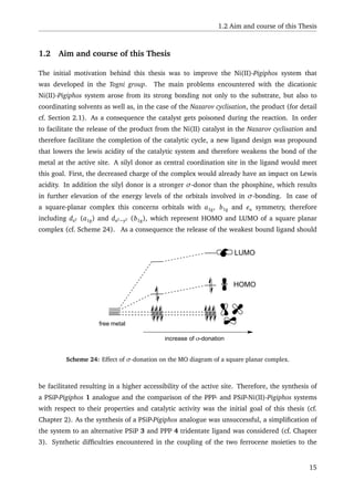
3.2 Synthetic strategy
In order to introduce planar chirality at the ferrocene moieties during the synthesis of the
PSiP-pincer like ligand 3 the sulfoxide route described by Kagan and co-workers[75]
was chosen
(cf. Paragraph 1.1.2.2). Starting from ferrocene the chiral p-tolyl-ferrocenyl-sulfoxide 16 is
easily synthesised as reported by Ribière et al.[204]
Selective ortho-lithiation then should yield
either the phosphine 33 or the silane 34 as needed. In a second step, the sulfoxide can be
substituted by another electrophile using t-BuLi (cf. Scheme 41).
An analogous route should yield the corresponding PPP analogues 4. As double lithiation of a
37](https://image.slidesharecdn.com/17dafaa7-bb25-4952-a328-ce8054639453-151111071008-lva1-app6892/85/eth21627-57-320.jpg)
![3 Synthetic approaches towards a chiral PSiP-Pincer ligand
Fe
Fe
Si
P P
H
R
Ph2Ph2
Fe
S p-tol
O
1. LDA
2. ClPPh2
3. BH3-THF
Fe
S p-tol
OPPh2
H3B
Fe
S p-tol
O
1. LDA
2. RHSiCl2 Fe
Fe
Si
H
S S
toltol
O
O
R
1. t-BuLi
2. RHSiCl2
3. NEt3
1. t-BuLi
2. RHSiCl2
Fe
Fe
Si
H
P P
Ph2Ph2
R
R = Me, Ph
34
35
3
3
Scheme 41: Proposed synthetic routes towards the PSiP-pincer like ligand 3.
molecule would be necessary in order to obtain (SFc,SFc)-3 or (RFc,RFc)-4 the convergent route
yielding the opposite enantiomers should be more feasible.
3.3 Synthetic challenges
3.3.1 Synthetic approach towards the PSiP-pincer like ligand 3
The synthetic approach towards the borane protected phosphine 33 as described by Riant
et al.[75]
was reproduced without any problems in a reasonable yield. Problems were not
faced until the attempt of double substitution of dichloromethylsilane in the second step,
which yielded none of the desired material. Reaction of the deprotected phosphine sulfoxide
also failed to yield the desired product upon lithiation with t-BuLi and subsequent quenching
with dichloromethyl silane. Approaching the target compound by first double substituting the
silicon moiety gave the bis sulfoxosilane 34 in a 30 % yield. While the second substitution gave
only minimal amounts of what could be considered to be the target compound, considering
31
P-NMR (δ –18.5 and –19.71) and MALDI-MS (m/z calcd: 783.12 found: 784.12 [M + H+
]).
Several attempts of optimising reaction conditions (temperature, solvents, reaction time) were
unsuccessful, despite the scale of the reaction, only amounts suitable for NMR analysis could
be isolated. Therefore other approaches had to be taken into consideration (cf. Chapter 3.3.3).
38](https://image.slidesharecdn.com/17dafaa7-bb25-4952-a328-ce8054639453-151111071008-lva1-app6892/85/eth21627-58-320.jpg)
![3.3 Synthetic challenges
3.3.2 Synthetic approach towards the PPP-pincer analogue 4
Similarly to the synthesis of the PSiP-pincer like ligand, 3, two approaches were fol-
lowed. In the first approach, the ferrocenyl sulfoxide 16 was first substituted by using
chlorodiphenylphosphine and subsequently protected with borane. The resulting phos-
phinoferrocenyl sulfoxide 33 was then reacted with one equivalent of t-BuLi and half an
equivalent of dichlorophenylphosphine. As was observed during the synthesis of 3 (vide
supra), this approach failed to yield the desired product. Coupling the ferrocenes over the
phenylphosphine moiety in the first reaction step, gave a low yield of about 18 % in inital
efforts. The second step led to only trace amounts of the target material in a product mixture.
The product was identified in the mixture by ESI-HRMS (calcd: 846.1198, found: 846.1254
[M+
]), encouraging further effort in the improvement of the synthesis. Stepwise lithiation of
the bissulfoxophosphine 5 was attempted in order to avoid a route over a double anion (cf.
Scheme 42).
Fe
Fe
P
P
Ph
Ph2
Fe
Fe
P
S S
toltol
O
O
Ph
1. t-BuLi
2. ClPPh2 S
tol
O
1. t-BuLi
2. ClPPh2 Fe
Fe
P
P
Ph
Ph2
P
Ph2
5 4
Scheme 42: Proposed stepwise lithiation of 5.
Initial efforts to develope a one-pot reaction lead to the formation of a mixture of phosphines.
Introduction of a work-up and filtration over silica in DCM after the first lithiation increased
the yield of the desired final product to an NMR-detectable amount. Seperation by flash
column chromatography gave a mixture of three major compounds, as shown by HPLC
(OD-H, n-hexane/i-PrOH 95:5, 0.7 ml/min, tR: 8.05, 8.47, 8.72 min). As further attempts at
purification were unsuccessful, preparative HPLC was used to further separate the mixtures
under the optimised conditions determined by analytical HPLC (vide supra). These efforts led
to a slightly better but still incomplete seperation. Three fractions were collected, of which
the second (tR: 7.88 – 8.49 min) contained the majority of the desired product, which was
fully characterised. One of the side products separated, could also be characterised and was
found to be diphosphine 35 (cf. Scheme 43).
39](https://image.slidesharecdn.com/17dafaa7-bb25-4952-a328-ce8054639453-151111071008-lva1-app6892/85/eth21627-59-320.jpg)
![3.4 The sulfoxophosphine ligand 5
Fe
Fe
R''
E
Fe
Fe
R''
E
P P
Ph
PhPhPh
S S
toltol
O
O
LiR'
ECl2R''Fe
R
S
tol
O
or
E = SiH, P
R = PPh2, H
R' = t-Bu, i-Pr2N
R'' = Me, Ph
E R R R yield [%]
Si–H Me PPh2 t-Bu 0
Si–H Me H i-Pr2N 16 – 33
P Ph PPh2 t-Bu 0
P Ph H i-Pr2N 18 – 45
Table 4: Generalised scheme for the coupling step in the synthesis of 3 and 4 and the yields corre-
sponding to the respective reactions.
1
H-NMR. As the epimerisation barrier for phosphines usually lies around 30 kcal/mol[205,206]
5
may be described most strictly as a C1 symmetric molecule at rt, therefore the hydrogen atoms
corresponding to each other on the ferrocenyl and tolyl groups are diastereotopic, hence the
different chemical shifts. The large difference in the chemical shifts of the two Cp rings with
a ∆δ of 0.72 ppm is remarkable. Although this observation seemed quite astonishing at first,
X-ray structure determination of crystals grown from DCM/n-hexane gave rise to a possible
explanation for this strong shift (cf. Figure 5).
The tolyl group on S(1) is oriented in such a way, that the aryl ring lies 3.49 Å away from
the next Cp carbon bound to Fe(1), facing the Cp with the ring plane of the tolyl group.
This T-shaped orientation to each other may be due to a π–π interaction. Therefore, it can
be assumed that a similar conformation is predominantly present in solution and the ring
current of the tolyl group enhances the field at the Cp hydrogens leading to the upfield
shift of about ∆δ 0.72 ppm observed in 1
H-NMR. The aryl ring on S(2) is oriented in nearly
the opposite direction with regards to the ferrocene moiety (cf. Table 5), comparable to the
reported structure of p-tolylferrocenyl sulfoxide.[207]
As a consequence the S(2)-aryl lies face
to face with the phenyl ring on P(1) in an almost parallel fashion (angle between ring planes
is 5.87°) at a distance around 3.8 Å, implying that a parallel-displaced π–π-interaction is
present.[208]
41](https://image.slidesharecdn.com/17dafaa7-bb25-4952-a328-ce8054639453-151111071008-lva1-app6892/85/eth21627-61-320.jpg)
![3 Synthetic approaches towards a chiral PSiP-Pincer ligand
P1 C2
C1
S1
O1 C11
C35
C19
C18
O2
S2
C28
Fe2
Fe1
Figure 5: X-ray crystal structure of the SPS-ligand 5.
dihedral Angle [°] dihedral Angle [°]
C(11)–S(1)–C(1)–C(2) –115.8(2) C(28)–S(2)–C(18)–C(19) 89.8(2)
O(1)–S(1)–C(1)–C(2) 132.67(19) O(2)–S(2)–C(18)–C(19) –21.0(2)
C(35)–P(1)–C(2)–C(1) 163.07(19) C(35)–P(1)–C(19)–C(18) –75.3(2)
Table 5: Selection of dihedral angles of compound 5.
The S(1)tolyl facing the Cp on Fe(1) also has a significant impact on the C(1)–S(1)–C(11)
angle which is widened by about 5° in comparison to the C(18)–S(2)–C(28) angle, while the
O–S–Fc angle is conversely widened around the S(2) moiety (cf. Table 6).
Angle [°] Angle [°]
C(1)–S(1)–C(11) 104.24(10) C(18)–S(2)–C(28) 99.42
O(1)–S(1)–C(1) 104.93(11) O(2)–S(2)–C(18) 109.05(10)
O(1)–S(1)–C(11) 106.28(10) O(2)–S(2)–C(28) 106.11(11)
Table 6: Bond angles around the sulphur atoms of 5.
Although one would expect that bond angles around the phosphorus atom should increase
42](https://image.slidesharecdn.com/17dafaa7-bb25-4952-a328-ce8054639453-151111071008-lva1-app6892/85/eth21627-62-320.jpg)
![3.4 The sulfoxophosphine ligand 5
with more sterically demanding groups,[209]
compound 5 shows narrower angles around P(1)
than diferrocenylphenylphosphine reported by Houlton et al.[210]
except for the angle between
a ferrocenyl substituent and the phenyl substituent (cf. Table 7).
compound 5 diferrocenylphenylphosphine[210]
Angle [°] Angle [°]
C(2)–P(1)–C(19) 98.55(10) C(24)–P–C(35) 100.0(5)
C(2)–P(1)–C(35) 99.30(10) C(35)–P–C(51) 101.0(5)
C(19)–P(1)–C(35) 99.30(10) C(24)–P–C(51) 98.6(5)
Table 7: Comparison of bond angles around the phosphine of compound 5 and diferro-
cenylphenylphosphine.
3.4.2 Complexation Experiments
A variety of experiments were performed in order to prepare complexes of ligand 5. The
focus of the complexation experiements was limited to d8
metals, except for one complexation
experiment using a Pd0
precursor. Most of the complexation reaction products could not be
completely characterised, as only inconclusive 1
H-NMR spectra were obtained particularly
in case of the rhodium and iridium complexes. Therefore 31
P-NMR and HRMS were used as
indicators for complexation when possible. Evidence of complex formation was found in five
experiments, for which a variety of MS and NMR methods were used (cf. Table 8).
Metal precursor MS 31
P-NMR 1
H-NMR NOESY X-ray
[(C2H4)2RhCl]2 n.a. × inconclusive n.a. n.a.
[(COD)RhCl]2 × × inconclusive n.a. n.a.
[(COE)2IrCl]2 × × inconclusive n.a. n.a.
[Pd(COD)Cl2] × × × n.a. ×
[Pt(COD)Cl2] × × × × n.a.
[Pd2(dba)3] n.a. inconclusive n.a. n.a. n.a.
Table 8: Analytical data available for 5-metal complexes.
Although analytical data for the rhodium complexes is sparse, formation of a complex is
43](https://image.slidesharecdn.com/17dafaa7-bb25-4952-a328-ce8054639453-151111071008-lva1-app6892/85/eth21627-63-320.jpg)
![3 Synthetic approaches towards a chiral PSiP-Pincer ligand
clearly indicated by 31
P-NMR. A doublet signal at δ 56.5 ppm with a coupling constant JRhP of
170 Hz independent of the precursor used is observed. In order to rule out the possibility that
the doublet observed corresponds to two signals from two different species, the spectrum was
measured using a 300 MHz, 400 Mhz and 500 MHz NMR confirming the coupling. (cf. Figure
6)
54.0 ppm55.056.057.058.0
202.1 MHz 31P{1H} NMR
162.0 MHz 31P{1H} NMR
121.5 MHz 31P NMR
Figure 6: 103
Rh –31
P-coupling measured at different field strengths.
In addition to the signal showing the Rh–P-coupling, a singlet at δ 26.4 ppm was observed in
case of the rhodium complex synthesised using [Rh(C2H4)2Cl]2 as a precursor. This implies
that a portion of the ligand 5 is only bound over the sulfoxide moieties to rhodium thereby
leaving the phosphorus uncoordinated. If ligand 5 is reacted with [Rh(COD)Cl]2 the singlet
signal is shifted upfield by ∆δ 0.7 ppm. This suggests that some of the precursor’s ligands
might be included in the complex formed, causing differences in chemical shifts. From this
information, the presence of a large variety of complexes from mononuclear to multi nuclear
complex clusters could be possible. MALDI-TOF-HRMS measurements show a single signal
at m/z 859.9564 corresponding to the molecular formula C40H35Fe2O2PRhS2 which would
fit the formula [RhL]+
ion, with L being 5. In case of the reaction of 5 with [Ir(COE)2Cl]2
a brown powder was isolated that showed a 31
P-NMR shift of δ –4 ppm and a weak signal
44](https://image.slidesharecdn.com/17dafaa7-bb25-4952-a328-ce8054639453-151111071008-lva1-app6892/85/eth21627-64-320.jpg)
![3.4 The sulfoxophosphine ligand 5
in MALDI-TOF-HRMS for C80H70Fe4IrO4P2S4, corresponding to [IrL2]+
. These were the
only indications of possible complex formation with iridium(I) and ligand 5. Reacting
[Pd(COD)Cl2] with ligand 5 yielded a red powder that showed a 31
P-NMR shift at δ 44 ppm.
(In the 1
H-NMR significant chemical shifts for the protons close to the metal moiety could be
observed as well as line broadening. Some signals are more strongly affected than others in
terms of those two parameters.) MALDI-TOF-HRMS showed a weak signal at 859.9561, which
corresponds to [PdL]+
. Attempts to synthesis a Pd(0) complex by reacting [Pd(dba)] with
ligand 5 gave inconclusive results in 31
P{1
H}-NMR, which showed two very broad signals at
δ 28.3 and 26.6 ppm. A platinum(II) complex of 5 was synthesised by dissolving the ligand
in DCM with [Pt(COD)Cl2] yielding a yellow powder. 31
P{1
H}-NMR of the compound showed
a peak at δ 21.1 ppm with platinum satellites having a coupling constant of JPPt = 3.7 kHz,
while in MALDI-TOF-HRMS a signal corresponding to [PtLCl2 + Na]+ was detected. All of
the complexes mentioned showed poor solubility in ether, toluene or benzene, but they were
moderately soluble in chloroform and THF. They also showed moderate to good solubility
in DCM and pyridine. In order to obtain single crystals, a variety of crystallisation methods
were applied, using different solvent systems. While most attempts resulted in decomposition
of the complexes in solution or precipitation of a powder, crystallisation of [PdLCl2] by gas
phase diffusion of benzene into a THF solution of the complex at –20 ◦
C was successful. The
resulting single crystals were of poor quality, preventing refinement of the crystal structure
further than to an R-value of 8.41 %. The low quality of the crystals may be explained by
the high solvent to complex ratio in the crystals and the low crystallisation temperature. Two
molecules of the platinum complex crystallised together with ten benzene molecules and one
THF molecule. In addition to the disorder of the solvent molecules, this might also have lead
to cracks in the crystals due to solvent evaporation during the short period of time the crystals
were at rt. However, a reasonable structural model could be obtained from the solution of the
crystal structure, showing that the phosphine as well as one sulfur moiety coordinate to the
platinum centre, while the other two coordination sites are occupied by two chlorido ligands
(cf. Figure 7).
This structure was also corroborated by 2D-NMR data of the platinum(II) complex. The
NOESY spectrum showed a contact between protons of the tolyl group on S(2) (δ 8.06 ppm)
and protons on the phenyl ring (δ 7.70 ppm; cf. Scheme 44). This contact is only possible if
one sulfoxide is not coordinated to the metal centre, thus allowing it to move freely into a
conformation allowing contact.
The fact that only one sulfur is bound to the metal centre is not surprising, as it is known
45](https://image.slidesharecdn.com/17dafaa7-bb25-4952-a328-ce8054639453-151111071008-lva1-app6892/85/eth21627-65-320.jpg)
![3 Synthetic approaches towards a chiral PSiP-Pincer ligand
P1
S1
S2 O1
O2
Pd1
Cl2
Cl1
Figure 7: Structure of the dichloropalladium(II) complex of 5.
Fe
Pt SCl
O
P
Fe
SO
Cl
NOE contact
5
Scheme 44: Observed NOE contact in the dichloroplatinum(II) complex of 5.
that sulfoxide bound over the sulfur moiety to the metal have a strong trans labilising
effect.[211–213]
Therefore, the only accessible position for the second sulfur moiety, which
lies trans to the other sulfur donor, in case of a square planar coordination around the
metal, is strongly disfavoured. Only coordination by the oxygen atom can be taken into
consideration,[214]
but seems unlikely considering the arguments mentioned above. Tem-
perature dependent 1
H-NMR of the palladium complex showed, that at 303 K the signals
corresponding to both tolyl groups are close to the fast exchange limit with regard to rotation
around the S–tol bond. Also the phenyl group shows fast exchange with respect to rotation
around the P–Ph bond. When the temperature is decreased, the signals corresponding to the
phenyl protons and the protons on the tolyl group on S(1) (cf. Figure 7) become broader,
46](https://image.slidesharecdn.com/17dafaa7-bb25-4952-a328-ce8054639453-151111071008-lva1-app6892/85/eth21627-66-320.jpg)
![3.4 The sulfoxophosphine ligand 5
with the phenyl proton signals coalescing at 223 K, while the protons on the tolyl group on
S(2) remain in fast exchange (cf. Figure 8). Assuming that the chemical shift difference
between the exchanging protons on the corresponding aromatic rings are similar, when
the slow exchange limit is reached, the energy barrier to the rotation is the lowest in case
of the tolyl group on S(2). This implies that the coordination of S(1) and the phospho-
rus to the palladium have an effect on the rotational barrier of the attached aromatic systems.
7.07.58.08.5
223
233
243
253
263
273
283
293
303
ppm
T/KS(1) P(1) S(2) P(1) S(1) S(2)
Figure 8: Temperature dependent 1
H-NMR of the dichloropaladium(II) complex of 5.
3.4.3 Catalytic experiments
The complexes of ligand 5 were tested for their catalytic activity in selected reactions. The
rhodium complex of ligand 5, synthesised from [Rh(COD)Cl]2, was tested in Miyaura-Hayashi
reaction following the reaction procedure by Dornan et al.[215]
Initial attempts at 40 ◦
C gave
high yields (up to 99 %), but negligible enantiomeric excess. At 0 ◦
C no product is observed,
however, the best conditions were found to be around room temperature giving 60 % yield
and up to 19 % ee (cf. Table 9). Although the enantiomeric excess achieved is only marginal,
47](https://image.slidesharecdn.com/17dafaa7-bb25-4952-a328-ce8054639453-151111071008-lva1-app6892/85/eth21627-67-320.jpg)
![3 Synthetic approaches towards a chiral PSiP-Pincer ligand
it implies that the chiral ligand is somehow involved in the catalytic cycle.
O B
OHHO
cat.
EtOAc
O
Rha
, PhB(OH)2, T, t, yield ee
mol% equiv ◦
C h % %
4 4 40 24 99.5 rac
4 4 40 1 40 rac
4 1.5 40 24 95 rac
2 4 40 1 60 rac
4 4 0 24 0 n.a.
4 4 rt 24 14 16
4 4 rt 4 11 15
a
under the assumption that the rhodium complex
of ligand 5 has a molecular formula of the type
[C40H35ClFe2O2PRhS2]n
Table 9: Rhodium catalysed Miyaura-Hayashi reaction.[215]
The dichloropalladium complex of 5 was tested in allylic substitution of diphenylallyl acetate
with dimethylmalonate. The isolated complex was used initially, and was synthesised starting
from [Pd(COD)Cl2]. The reaction was performed at 0 ◦
C for 4 h yielding 7 % of the desired
product with 82 % ee of the (S) enantiomer. As the isolated dichloropalladium complex
showed such low activity, a catalysis was run with the palladium catalyst generated in situ,
by adding ligand 5 and bis((1,3-diphenlallyl)bromopalladium(II)). Although a higher yield
was achieved (90 %), the main catalytically active species in the reaction mixture seemed
to be the precursor itself, as only a racemic mixture (2 % ee) was isolated. The problems
were overcome by using bis(allylchloropalladium(II)) as precursor to generate the catalyst
in situ with ligand 5. In a first attempt a yield of 97 % at an enantiomeric excess of 77 % ee
was achieved. Change of parameters such as solvent, temperature and base did not show
significant impact on the enantiomeric excess (cf. Table 10). Still further optimisation may be
considered.
48](https://image.slidesharecdn.com/17dafaa7-bb25-4952-a328-ce8054639453-151111071008-lva1-app6892/85/eth21627-68-320.jpg)

![4 Biferrocenylsulfoxides and Biferrocenylsulfides
4.1 Introduction
The work towards a chiral PSiP-Pincer ligand and its PPP analogue described in the previous
chapter yielded the SPS-ligand 5 as an intermediate, which itself showed promising features in
catalysis (cf. Chapter 3.4). The ligand 5 formed a two coordinate complex with palladium and
platinum, as the second sulfoxide cannot coordinate over the sulfur moiety to the metal centre
due to the strong trans-labilising effect of sulfur-bound sulfoxides.[211–213]
In order to form a
complex involving both sulfoxides, they need to be in a cis arrangement. This requirement can
be satisfied by removing the phosphine as linking moiety between the two ferrocenyl groups
resulting in a bisferrocenyl-disulfoxide (BiFeSO) (cf. Scheme 45).
Fe
Fe
S
S
R
O
R
O
Scheme 45: Generalised structure of BiFeSO.
4.1.1 Sulfoxide ligands
Chiral sulfoxides have been shown to be fairly stable towards epimerisation, activation en-
thalpies for pyramidal inversion for diaryl and alkyl aryl sulfoxides reported to be ∆H‡
= 35 –
42 kcal/mol by Rainer et al.[216]
(cf. Table 11).
As a consequence, racemisation of enantiopure sulfoxides only takes place at temperatures
around 200 ◦
C, well above the decomposition temperature of several sulfoxides such as the
cis-elimination of 1,2-Diphenyl-1-propyl phenyl sulfoxide.[217]
Therefore, sulfoxides can be
considerd sufficiently optically stable to be isolated as enantiopure compounds and stored.
Synthetic routes towards enantiomerically pure chiral sulfoxide are manifold[218,219]
making
them of high interest for use in stereoselective synthesis. Solladié first reported extensively on
the use of sulfoxides as chiral auxiliaries in asymmetric synthesis in 1981[220]
following brief
descriptions in earlier reviews.[221,222]
Today the use of sulfoxides as chiral auxiliaries is well
established.[223]
51](https://image.slidesharecdn.com/17dafaa7-bb25-4952-a328-ce8054639453-151111071008-lva1-app6892/85/eth21627-71-320.jpg)
![4 Biferrocenylsulfoxides and Biferrocenylsulfides
p-tol
S
OR
R
S
O
p-tol
∆H‡
, ∆S‡
, Ea, logA,
R kcal
mol
kcal
mol·K
kcal
mol
sec−1
2,4,6-(CH3)3C6H2 35.4 1.3 36.3 13.7
2-CH3C6H4 36.6 –2.8 37.5 12.8
C6H5 36.2 –5.1 37.2 12.3
1-Adamantyl 42.0 3.8 43.0 14.3
CH3 37.4 –8.0 38.4 11.7
Table 11: Activation parameters for the racemisation of p-tol–SO–R in p-xylene.[216]
Another field of application for enantiomerically pure sulfoxides is in the synthesis of ligands
that are potentially useful in asymmetric catalysis. In 1976, James et al. reported the first
asymmetric catalysis employing a chiral sulfoxide.[224]
Inspired by known DMSO complexes,
that showed activity in hydrogenation reactions they synthesised the ruthenium complexes
fac-[RuCl3(R R SO)3]−
and cis-[RuCl2(R R SO)4] using different racemic sulfoxides and were
able to prove their activity in olefin activation for some substrates. The only enantiomerically
pure complex with respect to the sulfur moiety they were able to isolate was [RuCl2(MeSOp-
tol)3], which failed to give any enantiomeric excess in hydrogenation reactions. Ironically,
a succesful asymmetric hydrogenation was achieved with a sulfoxide ligand bearing a chiral
centre at one of the alkyl groups, namely iso-pentane. Using that ligand they achieved an
enantiomeric excess of 12 % ee. A year later, inspired by the DIOP ligand reported by Kagan
and Dang,[225]
James and McMillan reported the synthesis of DIOS, BDIOS and DDIOS from the
known dithiol 36 (cf. Scheme 46). Based on those ligands, James and McMillan synthesised
a variety of complexes, of which [RuCl2(DIOS)(DDIOS)] gave the best results with regard to
enantiomeric excess, delivering a value of 25 % ee (cf. Scheme 47).[224,226]
Later approaches towards catalytic hydrogenation relied mainly on non C2 symmetric biden-
tate ligands containing a heteroatom as the second donor, with the reported enantiomeric
excesses ranging from 0 – 75 % ee.[227–229]
Of these examples, the work on iridium-catalysed
transfer hydrogenation by van Leeuwen’s group is particularly interesting, as it shows the im-
pact of the chiral centre at the sulfoxide on the enantiomeric excess of the product (cf. Table
12).[229]
52](https://image.slidesharecdn.com/17dafaa7-bb25-4952-a328-ce8054639453-151111071008-lva1-app6892/85/eth21627-72-320.jpg)
![4.1 Introduction
O
OMe
Me
CH2SH
CH2SH
H
H
1. MeI, NaOH
2. H2O2
O
OMe
Me
CH2SOMe
CH2SOMe
H
H
36
1. BnBr, NaOH
2. H2O2
H2O, H+
DIOS
O
OMe
Me
CH2SOBn
CH2SOBn
H
H
O
OMe
Me
CH2SOMe
CH2SOMe
H
H
BDIOS DDIOS
Scheme 46: Synthesis of DIOS and its derivatives from dithiol 36.[224,226]
O
OH
O
HO
2.6mol% [RuCl2(DIOS)(DDIOS)
H2 44psi, 55°C, 168h
O
OH
O
HO
49%, 25%ee
Scheme 47: Asymmetric hydrogenation of itaconic acid using [RuCl2(DIOS)(DDIOS)] by James and
McMillan.[224,226]
During the 1990s, most work published on sulfoxide containing ligands in asymmetric catal-
ysis utilised ligands containing at least one additional heteroatom donor. Their application in
asymmetric catalysis has been complemented by catalytic Diels-Alder-reaction, allylic substitu-
tion and diethylzinc addition to benzaldehyde (for further details cf. the review by Fernández
and Khiar[218]
and references therein). During that time, publications on asymmetric catalysis
with "pure" bis-sulfoxide ligands appeared sporadically. Nonetheless, the first asymmetric, cat-
alytic Diels-Alder reaction using a sulfoxide ligand was among them.[230]
The ligands used by
Khiar et al. are readily accessible from the known (R)-methyl p-tolyl sulfoxide and commer-
cially available (S)menthyl p-toluenesulfinate in a one- ((S,S)-bis-p-tolylsulfinylmethane 37)
and three-step ((S,S)-bis-p-tolylsulfinylpropane 38) reactions, respectively (cf. Scheme 48).
53](https://image.slidesharecdn.com/17dafaa7-bb25-4952-a328-ce8054639453-151111071008-lva1-app6892/85/eth21627-73-320.jpg)
![4 Biferrocenylsulfoxides and Biferrocenylsulfides
O OH
Ir(I), ligand
HCO2H
S NH2Bn
O
OH
S NH2Bn
O
OH
conv., % ee, % conv., % ee, %
99 65 (S) 56 27 (R)
Table 12: Enantioselective transferhydrogenation with a chiral sulfoxide ligand by van Leeuwen and
co-workers.[229]
S
O
p-tol
1. LDA, THF, –78°C
2.
S
O
p-tol
O-menthyl
SS
H H
p-tol
p-tol
OO
38
1. 2.2 equiv LDA
2. 2.2 MeI
SSp-tol
p-tol
OO
Me
1. 1.5 equiv KHMDS
2. 2.2 MeI
SS
Me Me
p-tol
p-tol
OO
39
Scheme 48: Bis-sulfoxide ligand by Khiar and Fernández.[230]
Khiar et al. suggested that the iron(III) moiety in their catalyst would be bound to the oxygen
lone-pairs of the sulfoxides, due to the hard nature of the metal centre. Their catalytic system
showed a endo:exo ratio up to 96:4, with an enantiomeric excess of the endo-(S) product of
56 % ee for the Diels-Alder reaction of 3-acryloyl-1,3-oxazolidin-2-one with cyclopentadiene
(cf. Table 13).
Another example is given in the work of Tokunoh et al. using (S,S)-1,2-bis(p-
tolylsulfinyl)benzene (BTSB) as a ligand. Their ligand showed a moderate induction in allylic
substitution of up to 64 % ee with palladium(II).
Recently, interest in C2-symmetric bis-sulfoxide ligands for asymmetric catalysis has grown sig-
nificantly and the performance of new catalytic systems including bis-sulfoxides has reached
54](https://image.slidesharecdn.com/17dafaa7-bb25-4952-a328-ce8054639453-151111071008-lva1-app6892/85/eth21627-74-320.jpg)
![4.1 Introduction
NO
O O
FeI3L
COR
H
H
COR
COR
H
H
COR
endo
exo
(R)
(R)
(S)
(S)
ligand L yield, % endo:exo (S):(R)
37 74 95:5 68:32
38 78 96:4 78:22
Table 13: Stereoselective Diels-Alder reaction with a bis-sulfoxide ligand by Khiar et al.[230]
enantiomeric excesses that are comparable to those of known catalytic systems.[231–241]
In
2008, Dorta’s group found that C2 atropisomeric sulfoxides showed competitive performance
in Rh-catalyzed 1,4-addition of arylboronic acids to cyclohexenones, reaching up to 98 % ee
and 99 % yield.[233]
Their so called BINASO ligand, a 1,1’-binaphtyl derivative similar to Noy-
ori’s BINAP,[242]
can be synthesised in a single reaction starting from commercially available
materials (cf. Scheme 49). The resulting diastereomeric mixture can easily be separated by
column chromatography, giving ready access to all four diastereoisomers of p-tol-BINASO.
One year later, Dorta an co-workers presented a similar catalytic system using
dimethylbiphenyl-2,2’-diyl-bis(p-tolylsulfoxide) (p-tol-Me-BIPHESO; cf. Scheme 49) that
showed even higher selectivity in 1,4-additions, with an enantiomeric excess of 99 % ee at
98 % yield.[236]
Similar work has subsequently been published on rhodium catalysed 1,4-
additions using a variety of different C2-symmetric bis-sulfoxides as ligands by the groups of
Zhou and Li,[237]
Liao[238,239]
as well as Khiar and Fernández[240]
(cf. Scheme 50).
In addition to the reports of catalytically active rhodium complexes, there have only been a few
examples of bis-sulfoxide late-transition-metal catalysts in the recent years. One is the macro-
lactonisation via hydrocarbon oxidation reported by White and co-workers, using among other
sulfoxides[243,244]
(rac)-1,2-bis-(phenylsulfoxy)ethane together with palladium(II)acetate as a
precursor to achieve the macrocyclisation with high chemo-[244]
and regioselectivity.[245]
The
system proved effective enough to be used for the total synthesis of 6-deoxyerythronolide B
55](https://image.slidesharecdn.com/17dafaa7-bb25-4952-a328-ce8054639453-151111071008-lva1-app6892/85/eth21627-75-320.jpg)
![4 Biferrocenylsulfoxides and Biferrocenylsulfides
Br
Br
1. Li base; –78°C
2. (1R or 1S)-menthyl-
(S or R)-p-tolyl-
sulfinate, –78°C – rt
S
S
O
p-tol
O
p-tol
S
S
O
p-tol
O
p-tol
(Sa)-BINASO-
diastereoisomers
(Ra)-BINASO-
diastereoisomers
Br
Br
1. Mg0, toluene/THF (2:1),
reflux
2. (1R or 1S )-menthyl-
(S or R)-p-tolyl-sulfinate,
–40°C
S
S
O
O
p-tol
p-tol
S
S
O
O
p-tol
p-tol
(Sa)-BIPHESO-
diastereoisomers
(Ra)-BIPHESO-
diastereoisomers
Scheme 49: Syntheses of BINASO and BIPHESO ligands.[233,236]
in the second to last reaction step.[246]
The other example of late-transition-metal catalysis
using bis-sulfoxide ligands was very recently reported in a paper by Dorta’s group. They used
BINASO-platinum(II) complexes in hydroboration, giving Markovnikov and Anti-Markovnikov
products in a ratio up to 4:1, and diboration of styrene. However, although they used enan-
tiomerically pure BINASO, they did not observe any enantioselectivity in the formation of the
benzylic stereogenic centre (cf. Scheme 51).[241]
Due to these recent developments in catalysis with bis-sulfoxide ligands, the idea of creating
a BiFeSO ligand as depicted in Scheme 45 seemed very intriguing. This especially because it
would bear a chiral centre at the sulfoxide and have axial chirality like BINASO, presuming
that rotation around the ferrocene–ferrocene bond is hindered, and in addition planar chirality
at the ferrocene moieties.
4.1.2 Known Biferrocenyl compounds
More than thirty years after the first synthesis of biferrocene by Nesmejanowa and Pere-
walowa[247,248]
and ten years after the synthesis of BINAP,[242]
the syntheses of the first bi-
56](https://image.slidesharecdn.com/17dafaa7-bb25-4952-a328-ce8054639453-151111071008-lva1-app6892/85/eth21627-76-320.jpg)
![4.1 Introduction
MeO
MeO
S
S
O
O
R'
R'
S
S
O
O
R'
R'
O
R
O
O
R
O
R = CH2, CH2CH2
R' = t-Bu, p-tol
Zhou and Li
S
S
O
O Fe Fe
S S
O O
Liao Khiar and Fernández
Scheme 50: Bissulfoxide ligands used in rhodium catalysed enantioselective 1,4-addition of boronic
acid.[237–240]
O
BH
O
O
BH
O
or
1. 2mol% Pt-BINASO
DCM
2. NaOH/H2O2
OH
OH
Markovnikov anti-Markovnikov
O
B
O O
B
O
1. 2mol% Pt-BINASO
THF, rt
2. NaOH/H2O2
OH
rac
OH
Scheme 51: Hydroboration and diboration of styrene reported by Dorta and co-workers.[241]
ferrocenyl ligands were reported.[67,249]
Sawamura et al. reported almost simultaneously
the synthesis of 2,2”-bis(diphenylphosphino)-1,1”-biferrocene (BIFEP)[249]
and 2,2”-bis[1-
57](https://image.slidesharecdn.com/17dafaa7-bb25-4952-a328-ce8054639453-151111071008-lva1-app6892/85/eth21627-77-320.jpg)
![4 Biferrocenylsulfoxides and Biferrocenylsulfides
(diphenylphosphino)ethyl]-1,1”-biferrocene (TRAP).[67]
The BIFEP ligand was synthesised
from (diphenylphosphinyl)ferrocene to give the doubly oxidised BIFEP as a racemate, which
was resolved using dibenzoyltartaric acid before reduction to the enantiomerically pure (S,S)-
and (R,R)-BIFEP ligands (cf. Scheme 52).
Fe
PPh2
O
i-Pr2NMgBr–THF
Fe
P
O
Ph2
Mg
Br
Ni(0) (in situ)
Fe
PPh2
O
2
1. resolution
2. HSiCl3,
I2
Fe
PPh2
O
I
Fe
rac
Fe
Ph2P
PPh2
(R,R)- and (S,S)-BIFEP
Scheme 52: BIFEP-synthesis by Sawamura et al.[249]
The coupling to the biferrocene using nickel(0) was reported not to yield any meso-
biferrocene product, but only the two desired enantiomers. Treatment of BIFEP ligands with
PdCl2(CH3CN)2 gave a cis-chelated palladium complex. As they stated, the ligand "does not in-
trinsically have axial chirality,"[249]
but they stated a preferred conformation of the correspond-
ing palladium complex. This statement was substantiated by the work of Espino et al., who cal-
culated that the activation energy for the conformational change was ∆G‡
= 58 ±3kJ · mol−1
from the major to the minor and ∆G‡
= 54 ±3kJ · mol−1
from the minor to the major con-
former, on the basis of the ratios of the two atropisomers in temperature dependent NMR,
corresponding to a temperature of about 260 K for the conformational exchange.[250]
For the
synthesis of their BIFEP derivatives, they used an approach first described by Xiao et al.,[251]
which starts from an enantiomerically pure 1-iodo-2-(arylsulfinyl)ferrocene, which is coupled
to a biferrocene by an Ullmann coupling. The sulfoxide groups are then substituted with phos-
phines by treatment with t-BuLi and the corresponding electrophile (cf. Scheme 53).
Other than the cis-chelating BIFEP ligands, the TRAP-ligands synthesised by Sawamura et al.
58](https://image.slidesharecdn.com/17dafaa7-bb25-4952-a328-ce8054639453-151111071008-lva1-app6892/85/eth21627-78-320.jpg)
![4.1 Introduction
Fe
I
S
R
O
Fe
Fe
S
S
O
O
R RCu 1. t-BuLi
2. ClPR'2
Fe
Fe
S
R'2P
O
R 1. t-BuLi
2. ClPR''2
Fe
Fe
PR''2
R'2P
R = p-tol
R' = Ph, 3,5-Me2Ph, 3,5-Me2-4-OMe-Ph
R'' = Ph, 3,5-Me2Ph, 3,5-(CF3)2Ph
Scheme 53: Modular BIFEP-synthesis as reported by Xiao et al.
from Ugi’s amine showed trans-chelating abilities.[67,68]
Surprisingly, the TRAP ligands gave
higher enantiomeric excess in asymmetric hydrogenation than the BIFEP ligands.[252]
In order
to close the structural gap between the BIFEP and TRAP ligand families and in analogy to the
Walphos ligands, Zirakzadeh et al. have recently reported the synthesis and application of a
new type of biferrocene ligands as depicted in Scheme 54.[253]
Fe
Fe
PR2
R2P
Fe
Fe
R2P
Me
H
Me
PR2
Fe
Fe
PR2
R2P
Me
H
BIFEP TRAP Walphos-analogue
Scheme 54: The three diphosphino-biferrocene ligand families.
Although Xiao et al. created a synthetic route, which had a (diarylsulfinyl)-biferrocene inter-
mediate (cf. Scheme 53), such a BiFeSO type ligand, as depicted in Scheme 45, has been
neither studied nor purposefully synthesised to date. In this project, a simple two step synthe-
59](https://image.slidesharecdn.com/17dafaa7-bb25-4952-a328-ce8054639453-151111071008-lva1-app6892/85/eth21627-79-320.jpg)
![4 Biferrocenylsulfoxides and Biferrocenylsulfides
sis, starting from ferrocene to a BiFeSO derivative was developed and the structural properties
of the resulting compound were extensively investigated.
4.2 Synthesis and structural features of BiFeSO 6
The simplest possible approach towards a BiFeSO type ligand utilises easily accessible t-butyl-
ferrocenylsulfoxide generated by the reaction of ferrocenyllithium with enantiomerically pure
bis-(t-butyl)-thiosulfinate. The ortho lithiation can be achieved simply by the use of n-BuLi (cf.
Chapter 1.1.2.2). Coupling to the biferrocene was performed following a modification of the
procedure reported by Dong et al.[254,255]
Solid CuCN (0.5 equiv) was reacted with lithiated
t-butyl-ferrocenylsulfoxide at –30 ◦
C for about 20 min before the reaction mixture was satu-
rated with oxygen at –78 ◦
C to give a deeply red solution. Stirring under oxygen atmosphere
over night while allowing the reaction mixture to warm up to rt introduced the desired planar
chirality (cf. Scheme 55).
Fe
S
O
n-BuLi
THF, –78°C Fe
S
O
Li
1. 0.5 equiv CuCN
–30°C
2. O2, –30°C – rt
Fe
Fe
S
S
O
O
6
Scheme 55: Synthesis of BiFeSO 6.
Flash column chromatography gave two products showing 1
H-NMR signals that correspond
to the suggested structure. The first compound eluted (6a) slowly turned green in solution,
while forming a precipitate. On the other hand, the product that eluted as the last fraction
(6b) seemed to be stable in solution. In order to remove the ferrocenium formed quickly from
the first sample, a DCM solution of 6a was quickly washed with water and then concentrated
in vacuo. The combined yield of both products together was about 60 % with a ratio of 15:1
60](https://image.slidesharecdn.com/17dafaa7-bb25-4952-a328-ce8054639453-151111071008-lva1-app6892/85/eth21627-80-320.jpg)
![4.3 Computational experiments with regard to the rotational barrier of BiFeSO 6
Pd(II), Pt(II), Cu(I), Au(I)), without any success. The reason for the unsuccessful complex-
ation experiments with 6a and 6b are probably of a different nature. In case of 6b the only
explanation that could be given are the weak coordination properties of the molecules sulfox-
ide group. For 6a one would assume that the poor donor properties could be overcome by
the possibility of chelation of the metal, as the sulfur lone pairs are in close proximity to each
other. On the other hand, the accessibility of the coordination centre is probably very low in
comparison to BINASO, as the ferrocene groups enhance steric hindrance within the molecule
significantly.
4.3 Computational experiments with regard to the rotational barrier of
BiFeSO 6
In order to confirm the atropisomers (6a and 6b), quantum chemical calculations were per-
formed to give an estimate of the energy barrier to conformational change. Starting from
the structural data from X-ray crystallography, a relaxed conformation of BiFeSO 6b was first
calculated to give a starting point. Then the energies for different rotations around the dihe-
dral angle C(2)–C(1)–C(15)–C(16) (cf. Scheme 10) were calculated (cf. Section 4.3.1). For
practical reasons the calculated structures of 6 are referred to as conformations.
4.3.1 Computational details1
All equilibrium geometries were optimized using the B3LYP[256–258]
and BP86[257,259]
density
functional methods employing the Dunning correlation consistent basis sets (Ref) along with
Stuttgart-Köln-MCDHF-RSC-28-ECP pseudo potentials to model the iron atom core electrons.
All calculations were performed with the Gaussian G09 program suite[260]
. For the rotation
of the dihedral angle C(2)–C(1)–C(15)–C(16) (φ1) a potential energy surface scan was per-
formed with an incremental rotation angle of 30 degrees (ModRedundant keyword). After
each dihedral angle rotation the structure was allowed to optimize within 20 geometry op-
timization steps. For the calculations/prediction of the magnetic shielding tensors gauge-
including atomic orbitals (GIAO, also know as London orbitals)[261–264]
were employed.
4.3.2 Computational results
For the evaluation of the data produced by these calculations the electronic energies calcu-
lated after the last geometry optimisation step were compared to the angle between the two
1
Computational details were provided by Oliver Sala, who conducted the calculations.
63](https://image.slidesharecdn.com/17dafaa7-bb25-4952-a328-ce8054639453-151111071008-lva1-app6892/85/eth21627-83-320.jpg)
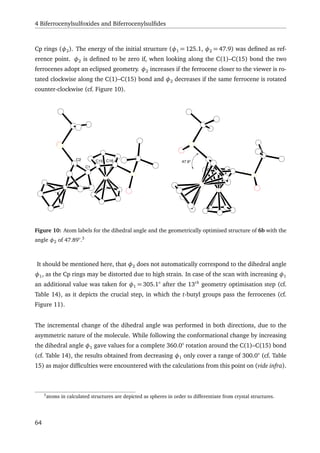
![4.3 Computational experiments with regard to the rotational barrier of BiFeSO 6
Figure 11: First time the ferrocene groups have to pass by the t-butyl groups in case of increasing φ2.
φ1, [°] φ2, [°] electronic
energy, [kcal/mol]
125.1 47.9 0.0
155.1 24.0 3.6
185.1 –27.3 7.2
215.1 –36.4 12.7
245.1 –49.4 23.9
275.1 –62.6 41.0
305.1a
–78.6 59.4
305.1 –130.7 26.1
335.1 –155.9 10.6
365.1 –167.0 13.5
395.1 –183.7 21.3
425.1 –246.6 15.6
455.1 –278.6 15.1
485.1 –297.8 19.0
a
after 13 geometry optimisation cycles.
Table 14: Data for incremental increase of φ1.
For the plot of the electronic energy versus φ2 the data of the two scans were consolidated
(cf. Figure 13). On both sides of the starting point at 47.9° a high energy barrier is predicted.
For increasing φ1, i.e. decreasing φ2, the highest energy is reached in the moment, in which
65](https://image.slidesharecdn.com/17dafaa7-bb25-4952-a328-ce8054639453-151111071008-lva1-app6892/85/eth21627-85-320.jpg)
![4 Biferrocenylsulfoxides and Biferrocenylsulfides
φ1, [°] φ2, [°] electronic
energy, [kcal/mol]
125.1 47.9 0.0
95.1 65.6 4.5
65.1 83.9 17.1
35.1 104.8 35.9
5.1 155.7 24.4
–24.9 185.0 22.3
–54.9 198.9 27.1
–84.9 211.4 35.1
–114.9 230.5 40.0
–144.9 249.1 45.1
–174.9 277.4 44.9
Table 15: Data for incremental decrease of φ1.
the t-butyl groups have to pass the ferrocene groups with an energy barrier of 59.4 kcal/mol.
For decreasing φ1, i.e. increasing φ2, the first local maximum in energy at 35.9 kcal/mol is
reached, when the two t-butyl groups have to pass each other. In both directions a local
minimum is reached after the first energy barrier is passed. This is the point at which the
conformation comes closest to the proposed structure of 6a. The relative energies at these
local minima differ largely from each other (10.6 kcal/mol at φ2 = –155.9° and 22.3 kcal/mol
at φ2 = 185.0°), as the t-butylsulfoxy groups are differently oriented in the two molecules due
to the different path in approaching the structure. Geometry optimisations for the proposed
structure of 6a have also been performed resulting in a relative energy difference to 6b of
9.1 kcal/mol (cf. Figure 12). This comes close to the energy of the conformer at φ2 = –155.9°,
where the main structural difference to the proposed structure is the different orientation of
one t-butyl group. The different orientation remains while φ1 increases. As a result the final
structure resulting after a 360.0° rotation of φ1 does not correspond to the initial structure
given by 6b (cf. Figure 14) with a difference of the angle between the Cp planes of 14.4° and
a resulting energy difference of 19.0 kcal/mol. A rotation around the S–Cp bond to reach the
initial configuration might be significantly hindered, as at least one of the t-butyl groups would
have to pass the opposing ferrocene to return to its initial conformation.
66](https://image.slidesharecdn.com/17dafaa7-bb25-4952-a328-ce8054639453-151111071008-lva1-app6892/85/eth21627-86-320.jpg)
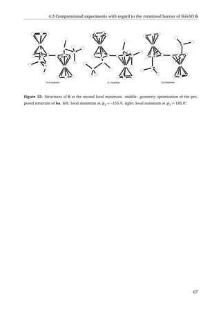
![4BiferrocenylsulfoxidesandBiferrocenylsulfides
-300 -250 -200 -150 -100 -50 0 50 100 150 200 250 300
10
20
30
40
50
60
Φ2
[°]
Eel
[kcal/mol]
Figure 13: Plot of the electronic energy versus φ2.
68](https://image.slidesharecdn.com/17dafaa7-bb25-4952-a328-ce8054639453-151111071008-lva1-app6892/85/eth21627-88-320.jpg)
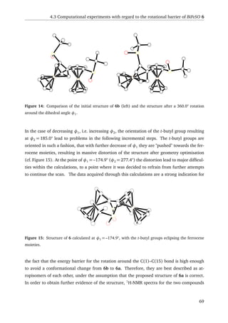
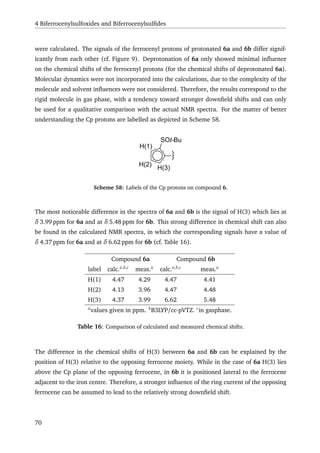
![4.4 Synthesis and structural features of BiFeS 7
4.4 Synthesis and structural features of BiFeS 7
As complexation experiments with BiFeSO 6b were unsuccessful (cf. Section 4.2), in an addi-
tional experiment it was reduced to give the dithioether 7 (BiFeS). It was assumed that the
thioether, as it provides two lone pairs at the sulfur atom instead of only one in case of the
sulfoxide, could more easily form a chelate and therefore would be more prone to undergo co-
ordination. The reduction of BiFeSO 6b to BiFeS 7 was achieved by refluxing it in dry toluene
with an excess of triethyl amine and trichlorosilane (cf. Scheme 59). Remaining starting mate-
rial was easily separated through column chromatography from the product. Recrystallisation
from DCM/n-pentane gave dark orange-red crystals suitable for X-ray diffraction (cf. Section
4.5).
Fe
Fe
S
S
O
O
20 equiv NEt3
40 equiv SiHCl3
toluene, reflux, 15h
Fe
Fe
S
S
6b 7
Scheme 59: Reduction of BiFeSO 6b to BiFeS 7.
As for BiFeSO 6b, a variety of complexation experiments were performed relying mainly on
DMS based precursors in order to take advantage of the possible chelating effect of the BiFeS
7. The attempts failed to yield an isolated complex. However, refluxing BiFeS 7 with HgBr2 in
toluene gave a small amount of a precipitate that appeared to be a new product. NMR analysis
seemed to indicate that an elimination of one of the t-butyl groups was taking place, similar
to the decomposition of di-t-butyl sulfide-mercury(II) chloride reproted by Biscarini et al. (cf.
Scheme 60).[265]
Attempts to increase the yield by further addition of HgBr2, longer reaction times or higher
temperature, as well as the addition of base in order to facilitate the elimination, were un-
successful. Attempts using other mercury precursor precursors, such as HgCl2 and Hg(CF3)2,
didn’t yield any detectable product at all, therefore no full characterisation could be per-
formed. As a final attempt BiFeS 7 was reacted with ZnEt2 in THF, but only the starting
material was isolated.
71](https://image.slidesharecdn.com/17dafaa7-bb25-4952-a328-ce8054639453-151111071008-lva1-app6892/85/eth21627-91-320.jpg)
![4 Biferrocenylsulfoxides and Biferrocenylsulfides
S
H2C
Hg
Cl
Cl Hg
Cl
ClH
S
CH2
H
Scheme 60: Decomposition mechanism of [t-Bu2SHgCl2]2 as proposed by Biscarini et al.[265]
4.5 X-ray structure of BiFeSO 6b and BIFES 7
As mentioned above, X-ray structures for both compounds BiFeSO 6b and BiFeS 7 were
measured. Both compounds crystallised in an orthorhombic cell system with a P212121 space
group and showed very similar structure (cf. Figure 16). The dihedral angles φ1 and the
angles between the two Cp-rings φ2 of the two compounds, as defined in Section 4.3, are
very similar to each other with values of φ1 = 125.0(3)° and φ2 = 49.4° for BiFeSO 6b and
φ1 = 125.9(2)° and φ2 = 48.6° for BiFeS 7. As expected the main difference between the two
compounds is found in the dihedral angles around the sulfur moieties, which differ in a range
of 8 – 14° (cf. Table 17). At the same time the angles at the sulfur atoms only differ marginally
in a range of 1 – 2°.
C2
C1
C16
C15
S2
C25
C11
S1
Fe2
Fe1
C1
C2
S1
O1
C15
C16
S2
O2
C25
C11
Fe1
Fe2
C17 C3
C3
C17
Figure 16: Structures including labels of BiFeSO 6b and BiFeS 7.
Concerning the bond lengths only marginal differences can be observed between the com-
72](https://image.slidesharecdn.com/17dafaa7-bb25-4952-a328-ce8054639453-151111071008-lva1-app6892/85/eth21627-92-320.jpg)
![4.5 X-ray structure of BiFeSO 6b and BIFES 7
Angle BiFeSO 6b [°] BiFeS 7 [°]
φ1 125.0(3) 125.9(2)
φ2 49.4 48.6
C2–S1–C11 102.23(10) 103.89(8)
C16–S2–C25 103.67(10) 105.73(8)
O1–S1–C2 111.02(10)
O2–S2–C16 110.67(9)
O1–S1–C11 107.02(10)
O2–S2–C25 105.87(10)
C11–S1–C2–C1 –85.0(2) –92.74(17)
C25–S2–C16–C15 –81.9(2) –94.92(17)
C11–S1–C2–C3 103.49(17) 93.33(15)
C25–S2–C16–C17 107.87(19) 93.88(17)
Table 17: Selected angles from the X-ray structures of 6b and 7.
pounds. Only the CCp–S bonds (S1–C2 and S2–C16) differ significantly from each other, with
a difference of about 0.02 Å (cf. Table 18) in correspondence to the known average Carom–S(3)
and Carom–S(2) bond lengths.[266]
At the same time the lengths of the Csp3
–S bonds are not
effected by the reduction of the sulfoxide to the sulfide.
Bond BiFeSO 6b [ Å] BiFeS 7 [ Å]
C1–C15 1.472(3) 1.465(2)
S1–C2 1.785(2) 1.7623(17)
S2–C16 1.781(2) 1.7632(18)
S1–C11 1.851(2) 1.8502(18)
S2–C25 1.851(2) 1.8546(18)
S1–O1 1.4977(18)
S2–O2 1.4978(16)
Table 18: Selected bond lengths from the X-ray structures of 6b and 7.
73](https://image.slidesharecdn.com/17dafaa7-bb25-4952-a328-ce8054639453-151111071008-lva1-app6892/85/eth21627-93-320.jpg)
![5 Side projects
5.1 Introduction
In addition to the research described in Chapters 2 to 4, complementary side projects were
undertaken to complement the findings of the primary work.
5.2 Acidity of [Ni(II)-(Pigiphos)L]2+
As [Ni(II)-(Pigiphos)L]2+
is a chiral Lewis acid (cf. chapter 2.1), a method to determine the
acidity of the dicationic complex would be of interest. However, due to the complexity of the
compound, a direct comparison with common Lewis acids is likely to be challenging. Still, an
estimation of its acidity could be made and would be of interest, especially for comparison
with other Pigiphos derivatives.
5.2.1 Fluoride Ion Affinity
Determination of acidity of Lewis acids has been a matter of more or less continuous interest.
For comparative studies Lewis acid interactions with α,β-unsaturated carbonyls and nitriles
have been used in combination with NMR-shifts and calorimetric studies to estimate Lewis
acidity.[267–270]
Fluoride ion affinity (FIA) is a more generally applicable method for acidity
determination and is often used. Because of the fluoride ion’s small size and high basicity,
it tends to react with almost all hard Lewis acids. By definition the FIA corresponds to the
negative enthalpy of the reaction of the Lewis acid with F−
in gas phase. There are several
FIA scales based on measurements, the precision of which is limited by problems stemming
from experimental factors that arise if reactions cannot be performed in the gas phase or if
lattice energies of the often solid products are not known.[271,272]
Also determination methods
often give variable results leading to relatively large uncertainties of around 10 %. Therefore
computational methods based on the isodesmic reaction (1) may be used to determine the
FIA,[273–276]
based on the experimental FIA value of OCF2.[271]
A + OCF−
3
→ AF−
+ OCF2 (1)
In the case of [Ni(II)-(Pigiphos)L]2+
neither approach would be feasible, as the compound
cannot be brought into the gaseous phase and at the same time is too complex to assess
computationally. So, comparative studies to known values are necessary to estimate the actual
FIA of the dicationic [Ni(II)-(Pigiphos)L]2+
system.
75](https://image.slidesharecdn.com/17dafaa7-bb25-4952-a328-ce8054639453-151111071008-lva1-app6892/85/eth21627-95-320.jpg)
![5 Side projects
5.2.2 Aim of the project
In order to estimate the FIA of [Ni(II)-(Pigiphos)L]2+
, the fluoride complex 8 had to be
synthesised first. The [fluoro-Ni(II)-(Pigiphos)]+
complex 8 could then be mixed with a Lewis
acid in a 1:1 ratio and the ratio of fluorinated Lewis acid and [Ni(II)-(Pigiphos)L]2+
could then
be estimated, preferably by 19
F-NMR. Therefore, for the reaction of [fluoro-Ni(II)-(Pigiphos)]+
(NiF+
) with a Lewis acid (A) (cf. (2)) K can be calculated from equation (3).
NiF+
+ A NiF2+
+ AF−
(2)
K =
[Ni2+
][AF−
]
[NiF+
][A]
(3)
Equation (3) can be rewritten as equation (4) by assuming that [Ni2+
] = [AF−
] and [NiF+
] =
[A]:
K =
[AF−
]2
[NiF+
]2
(4)
Now K can be calculated solely based on the integrals of the 19
F-NMR spectra and therefore
the Lewis acidity can be quantified relative to the competing Lewis acid. When K > 1 the FIA
value of the Lewis acid lies above the FIA value of [Ni(II)-(Pigiphos)L]2+
and vice versa for
K < 1.
5.2.3 Synthesis of [fluoro-Ni(II)-(Pigiphos)]+
The synthesis of the desired fluoride complex 8 was challenging. To minimise the influence
of the counter ion on the acid base reactions, the complex was synthesised from [Ni(II)-
(Pigiphos)L]2+
perchlorate by adding TBAF or TMAF as fluoride sources under different con-
ditions. Although later experiments showed that the complex was partially fluorinated, the
desired product could not be isolated in a satisfactory purity or yield. Attempts to force halo-
gen exchange starting from the chloro analogue by using fluoride based halogen scavengers
were equally unsuccessful. The desired fluoride complex 8 was synthesised by first forming
the Ni(0)-Pigiphos complex by reacting Pigiphos with [Ni(COD)2],[277]
followed by the addi-
tion of fluoropyridinium salt 39 as electrophilic fluorine source (cf. Scheme 61).
76](https://image.slidesharecdn.com/17dafaa7-bb25-4952-a328-ce8054639453-151111071008-lva1-app6892/85/eth21627-96-320.jpg)
![5.2 Acidity of [Ni(II)-(Pigiphos)L]2+
Fe
P
Fe
PPh2 Ph2P
Cy [Ni(COD)2]
tol, 1h at rt
Fe
P
Fe
Ph2P PPh2
Cy
Ni
N+F
BF4
-
tol, 24h at rt
Fe
P
Fe
Ph2P PPh2
Cy
Ni
F
+
BF4
-
39
8
Scheme 61: Synthesis of the [fluoro-Ni(II)-(Pigiphos)]+
8 from Pigiphos and [Ni(COD)2] using fluo-
ropyridinium salt 39
The deep red solid compound showed a very broad signal around δ –323 ppm in 19
F-NMR
as well as the presence of several impurities, while 31
P-NMR showed the presence of other
[Ni(II)-(Pigiphos)L]2+
complexes in addition to the desired product. The formation of the Ni–
F bond was unequivocally demonstrated by a 162 MHz 19
F,31
P-HMBC-NMR experiment, which
show correlations between the fluorine signal and the coordinated phosphorus atoms of the
Pigiphos ligand (cf. Figure 17).
Recrystallisation of the product from DCM/n-pentane lead to polycrystalline material as well
as some single crystals suitable for X-ray crystallography. Although the crystals were of poor
quality and therefore did not allow a complete solution of the crystal structure, Ni–F connec-
tivity could still be confirmed. No clear assignment of the NMR signals could be made due to
impurities, even after recrystallisation, as well as due to the broad signals mainly in 1
H-NMR,
the latter can be explained by inspection of the crystal structure of the fluoride complex 8.
As the solution of the crystal structure of the tetrafluoroborate salt 8 was not complete (vide
supra), the structure of the pentafluoro silicate salt of [fluoro-Ni(II)-(Pigiphos)]+
, synthesised
by Sandra Miloševi´c in our group, was used to determine the geometry at nickel (cf. Figure
18). The sum of the angles around the nickel(II) centre add up to 361°. Therefore the ge-
ometry is distorted from a perfect square planar configuration. This is further confirmed by
77](https://image.slidesharecdn.com/17dafaa7-bb25-4952-a328-ce8054639453-151111071008-lva1-app6892/85/eth21627-97-320.jpg)
![5 Side projects
102060
f2
50
(ppm)
40 30708090
-330
-325
-320
-315
f1(ppm)
Figure 17: 162 MHz 19
F,31
P-HMBC-NMR of [fluoro-Ni(II)-(Pigiphos)]+
8.
the angles F(1)–Ni(1)–P(2) = 175.49(9)° and P(1)–Ni(1)–P(3) = 162.74(4)°, which differ sig-
nificantly from 180° for a linear arrangement. The distorted square-planar geometry should
result in paramagnetic character. As a result of this geometric distortion, the quality of the
NMR spectra suffers due to line broadening and the concentration dependence of the absolute
chemical shifts.
P1
P2
Ni1
P3
F1
P1
P2
Ni1
P3
F1
Figure 18: X-ray structure of the [fluoro-Ni(II)-(Pigiphos)]+
. left: the structure from the tetraflorobo-
rate salt 8. right: the structure from the pentafluorosilicate salt.
78](https://image.slidesharecdn.com/17dafaa7-bb25-4952-a328-ce8054639453-151111071008-lva1-app6892/85/eth21627-98-320.jpg)
![5.2 Acidity of [Ni(II)-(Pigiphos)L]2+
In order to exclude exchange effects as the source of the signal broadening, a series of variable
temperature 19
F-NMR spectra were recorded. Temperature dependent 19
F-NMR spectra were
measured in a range between 193 K and 263 K. A large temperature dependence of chemical
shift of the coordinated fluoride was observed with an up-field shift from δ –315 ppm at 263 K
to δ –293 ppm at 193 K with the signal almost vanishing at 223 K (cf. Figure 19).
−285 −290 −295 −300 −305 −310 −315 −320 ppm
223
213
203
193
233
263
253
243
T/K
Figure 19: Temperature dependent 376.5 MHz 19
F-NMR of [fluoro-Ni(II)-(Pigiphos)]+
8.
As only a single signal was affected by the temperature change, namely the signal of the flu-
oride bound to the nickel(II) centre, an exchange of that fluoride is unlikely. The most likely
explanation is the configurational change between two tetrahedrally distorted configurations
around the nickel(II) moiety. At high temperature (above 233 K) the exchange between the
two configurations is fast enough to give an average value corresponding to a quasi square
planar complex. At low temperature (below 223 K) the exchange rate between the two con-
figurations becomes significantly slower than the time scale of the NMR experiment. As a con-
sequence, the paramagnetic term is fully expressed, and since the distorted configurations are
not averaged out, the resulting shift of ∆δ 22 ppm in a temperature range of 70 K is observed.
Due to the C1 symmetry of the complex, the two distorted configurations are not equivalent
to each other, as a consequence the paramagnetic term does not vanish completely at high
temperature, hence the concentration dependent chemical shifts, as well as line broadening
caused by paramagnetism are observed at rt. Due to the problems concerning the purification
of complex 8 and the inaccuracy of the fluoride’s integral in 19
F-NMR as a consequence of
paramagnetism the method was considered not to be suitable for FIA estimation.
79](https://image.slidesharecdn.com/17dafaa7-bb25-4952-a328-ce8054639453-151111071008-lva1-app6892/85/eth21627-99-320.jpg)
![5 Side projects
5.2.4 Summary
An attempt to quantify the FIA of the [Ni(II)-(Pigiphos)L]2+
resulted in the development of a
synthetic route towards a [fluoro-Ni(II)-(Pigiphos)]+
complex. The compound showed para-
magnetic properties in NMR, that can be explained through the measured crystal structure
and the dynamics of the complex were observed by temperature dependent 19
F-NMR. Unfor-
tunately, the synthesised system was found not to be suitable for FIA determination due to
purification difficulties as well as the paramagnetic character of the nickel(II) complex.
5.3 Towards a chiral ferrocenyl building block
In the course of synthetic work on the PSiP- and PPP-pincer analogues one of the principal diffi-
culties encountered was the oxygen transfer from the sulfoxide to electrophiles during the sub-
stitution reactions (cf. Chapter 3.3.3). Removal or substitution of the sulfoxide prior to the con-
cerned reactions could therefore be a possibility to avoid the problems encountered. In order
to introduce planar chirality, a chiral 1,2-disubstituted ferrocene containing substituents that
can be selectively substituted with another group would be required. One compound consid-
ered to be useful for such an application is bromo-2-(tri-n-butylstannyl)ferrocene 9. As prob-
lems due to oxygen transfer only were encountered either during the coupling of the two fer-
rocenes over a central moiety, using a dichlorosilane or a dichlorophosphine, or in the substi-
tution of the p-tolylsulfoxide with a chlorophosphine, bromo-2-(diphenylphosphino)ferrocene
40 was investigated as another compound able to circumvent the problems of the coupling
step.
5.3.1 The bromo stannyl ferrocene
Bromo-2-(tri-n-butylstannyl)ferrocene 9 was synthesised from the known (RFc,SS)-(p-
tolylsulfinyl)-2-(tri-n-butylstannyl)ferrocene[75]
41 by substituting the sulfoxide using t-BuLi
and dibromotetrachloroethane (cf. Scheme 62). During the course of this work, this re-
action was also reported by Zirakzadeh et al. in their attempt to synthesis new Walphos
analogues.[253]
Due to the n-butyl groups attached to the tin moiety, access to the ortho position is restricted.
Therefore, the reaction always yielded a mixture of bromo-2-(tri-n-butylstannyl)ferrocene 9
and (tri-n-butylstannyl)ferrocene in a ratio of 1:1 up to 2:1 in favour of the desired product
as determined by 1
H-NMR. As both products are highly apolar oils, their separation was
80](https://image.slidesharecdn.com/17dafaa7-bb25-4952-a328-ce8054639453-151111071008-lva1-app6892/85/eth21627-100-320.jpg)
![5.3 Towards a chiral ferrocenyl building block
Fe Fe
SnBu3
S
O
SnBu3
Br1. t-BuLi
2. CH2BrCH2Br
9
Scheme 62: Synthesis of bromo-2-(tri-n-butylstannyl)ferrocene 9.
challenging. Two flash column chromatographies over silica using n-pentane as eluent gave a
ratio of 4:1 of the desired product 9 to the side product (Zirakzadeh et al. encountered similar
problems), a purity that was considered sufficient for preliminary experiments.
For the selective substitution step three different approaches were considered. Initial attempts
were based on selective lithiation taking advantage of the fact that n-butylstannyl substituents
are not affected by t-BuLi due to steric hindrance. In a second step the stannyl substituent
could then be lithiated using n-BuLi. Another approach considered was the substitution of
the stannyl by following the method reported by Mita et al., using fluoride as a mild tin
activator.[278–281]
Although Stille coupling would not enable the synthesis of a PSiP-pincer
like ligand, as described in Chapter 3, the initial motivation for the synthesis of a chiral
building block, it was investigated for its utility in the synthesis of other chiral 1,2-substituted
ferrocenes (cf. Scheme 63).
Br
Fe
Sn1. t-BuLi
2. EX
Stille coupling
with RX
1. CsF
2. EX
E
Fe
Sn
Br
Fe
E
Br
Fe
R
9
Scheme 63: Suggested ways of selective substitution at the bromo-2-(tri-n-butylstannyl)ferrocene 9.
81](https://image.slidesharecdn.com/17dafaa7-bb25-4952-a328-ce8054639453-151111071008-lva1-app6892/85/eth21627-101-320.jpg)
![5 Side projects
5.3.1.1 Selective lithiation The simplest method for selective substitution is through se-
lective lithiation of the reactive sites. As mentioned previously (vide supra), the n-butylstannyl
substituent is usually unaffected by t-BuLi due to steric hindrance, while the bromine lithium
exchange is likely. Several attempts under different conditions (reaction times at different
temperatures) were performed using chlorodiphenylphosphine as an electrophile. The results
were comparable for all conditions applied. After work-up only traces of product (up to 5 %
NMR-yield with respect to compound 9) were present in the crude product. Flash column
chromatography lowered the yield further, while the applied starting material was recovered.
It was assumed that the access to the bromo substituent was hindered by the sterically de-
manding tri-n-butylstannyl group. Attempts using n-butyllithium lead to an almost 1:1 ratio
of lithiation of the stannyl and the bromo substituent.
5.3.1.2 Fluoride based tin cleavage The activation of the stannyl group by fluoride ad-
dition was considered as a preliminary approach. Experiments were performed on (tri-n-
butylstannyl)ferrocene. A variety of fluoride sources were tested, but no activation was ob-
served and further attempts were abandoned.
5.3.1.3 Stille Coupling A few Stille coupling experiments of bromo-2-(tri-n-
butylstannyl)ferrocene 9 to aromatic halides and pseudohalides were performed with
no success. Additionally, experiments coupling bromo-(tri-n-butylstannyl)ferrocene 9 to itself
were undertaken to see if a poly-Stille coupling to a poly 1,2-ferrocenyl or the synthesis
of 1,2,1”,2”-biferrocene by a double Stille coupling would be possible. Following reaction
conditions reported by Liebeskind et al.[282]
a small portion of impure material was obtained,
that showed the mass of the singly coupled product in HRMS (Dual MALDI/ESI: m/z calcd
for C32H43BrFe2Sn: 738.0262, found: 738.0251), but the structure could not be verified by
NMR. As for all the performed Stille couplings, also in this experiment the majority of the
starting material was recovered.
5.3.2 The Bromo phosphino ferrocene
As mentioned above, the primary motivation for the synthesis of a chiral building block,
was to circumvent problems encountered with the sulfoxide in the PSiP-pincer ligand syn-
thesis described in Chapter 3. A less sophisticated solution to do so was the synthesis of a
82](https://image.slidesharecdn.com/17dafaa7-bb25-4952-a328-ce8054639453-151111071008-lva1-app6892/85/eth21627-102-320.jpg)
![5.3 Towards a chiral ferrocenyl building block
1-bromo-2-phosphino-ferrocene as an intermediate between the sulfoxide and the pincer sys-
tem. To obtain the desired material (p-tolylsulfinyl)-2-[diphenylphosphino(borane)]ferrocene
33 was first treated with t-butyl lithium to give lithiated phosphinoferrocene and subsequently
quenched by a brominating agent. Initial attempts using bromine as bromination agent
gave yields less than 5 % (estimated by 1
H-NMR). Attempts using halon 2402 (2 equiv), 1,2-
dibromoethane (3 equiv) or 1,2-dichlorotetrabromoethane (2 equiv) gave comparable NMR
yields, slightly greater than 15 %. Due to the environmental impact of halon 2402 and
the health concern regarding the use of 1,2-dibromoethane, 1,2-dibromotetrachloroethane
seemed to be the ideal brominating agent for these purposes. The low yield is not a matter of
low conversion in the lithiation step, but seems to be due to incomplete bromination. The main
product obtained by this reaction was [diphenylphosphino(borane)]ferrocene, which could
not be seperated completely from the desired product by standard methods. Therefore, the de-
sired product was always obtained as a mixture with [diphenylphosphino(borane)]ferrocene
in varying ratios (from 1:3 to 1:1). Adjusting the reaction time, temperature or reagent
concentrations had no observable impact on the yield of the reaction, although under iden-
tical conditions the yields varied significantly from one experiment to the next (usually
between 10 and 20 %, with the exception of one experiment yielding 50 %). As all at-
tempts to separate bromo-2-[diphenylphosphino(borane)]ferrocene 33 from [diphenylphos-
phino(borane)]ferrocene were unsuccessful, the product mixture was just separated from the
starting material, as well as the t-butyl-p-tolyl sulfoxide generated during the reaction by flash
column chromatography using ether as an eluent. Then the product mixture was deprotected
by refluxing it in degassed diethylamine. Separation difficulties persisted after the deprotec-
tion, but small amounts of the desired product were obtained for characterisation by prepara-
tive HPLC.
5.3.3 Summary
In an attempt to create a enantiomerically enriched 1,2-substituted ferrocenyl build-
ing block, the syntheses of bromo-2-(tri-n-butylstannyl)ferrocene 9 and bromo-2-
[diphenylphosphino]ferrocene 40 were developed. In both cases severe purification
difficulties were encountered. The selective substitution reactions of bromo-2-(tri-n-
butylstannyl)ferrocene 9 performed met with little success. During the investigation of com-
pound 9, Zirakzadeh et al.[253]
published a similar synthesis of the same compound. Their
reported substitution of the stannyl group by iodine and the resulting enantiomerically en-
riched bromoiodoferrocene might provide new possibilities for selective substitution, includ-
ing the reported Negishi coupling. The synthesis of bromo-2-[diphenylphosphino]ferrocene 40
83](https://image.slidesharecdn.com/17dafaa7-bb25-4952-a328-ce8054639453-151111071008-lva1-app6892/85/eth21627-103-320.jpg)
![5 Side projects
showed, in addition to purification issues, low yields, rendering it impracticable as an ‘inert’
replacement of (p-tolylsulfinyl)-2-[diphenylphosphino(borane)]ferocene 33.
5.4 Ferrocenyl-(trifluoromethyl) sulfide
Due to the conformational restrictions of BiFeSO 6 imposed by the t-butyl groups (cf. Chap-
ter 4), a BiFeSO with a sterically less demanding group was considered to be of interest, as
it might more easily undergo a ‘configurational’ change that would favour the complexation
of a metal. Initial attempts included i-propyl and methyl substituents, in order to assess the
size at which the energy barrier allows for a ‘configurational’ change. But the coupling reac-
tions to the biferrocenes were unsuccessful. This is most probably due to the acidity of the
hydrogen α to the sulfoxide, leading to problems with lithiation.[80]
As the Togni group has
a long history of research on trifluoromethylation agents and trifluoromethylation,[283–289]
a
ferrocenyl-(triflouoromethyl) sulfoxide appeared as logical path to achieve the requirements.
5.4.1 Synthetic approach
In order to achieve enantiomerically pure bis-[2-(trifluoromethylsulfinyl)ferrocene],
ferrocenyl-(trifluoromethyl) sulfide had to be synthesised in a first step. The sulfide
would then be enantioselectively oxidised to give enantiomerically enriched ferrocenyl-
(trifluoromethyl) sulfoxide, suitable for the coupling reaction to the biferrocene.
Although ferrocenyl-(trifluoromethyl) sulfide has been previously reported by Rhode et
al.,[290]
due to the tedious preparation and inadequate characterisation this route has not
been considered. Initial attempts included the palladium-catalysed formation of ferrocenyl-
(trifluoromethyl) sulfide from bromoferrocene and AgSCF3 analogous to the Ar–SCF3 synthe-
sis reported by Buchwald and co-workers.[291]
As these attempts turned out to be unsuccessful,
the trifluoromethylation of ferrocene thiol using the alcohol and acid Togni reagents were in-
vestigated (cf. Scheme 64).
The major product obtained from the reaction of ferrocene thiol with the Togni reagents was
bisferrocenyl disulfide, due to the oxidation of the thiol by the iodine(III). Nonetheless, the
reaction of sodium ferrocenesulfide with the acid Togni reagent showed the formation of small
amounts of what seemed to be the desired product, with the best results being achieved by
performing the reaction in DCM at –78 ◦
C up to rt with no additives, yielding up to 10 % of the
desired product (identified by HRMS and NMR). Still the main product of the reaction was the
bisferrocenyl disulfide with 50 % and the absolute yields achieved did not exceed 60 mg as the
84](https://image.slidesharecdn.com/17dafaa7-bb25-4952-a328-ce8054639453-151111071008-lva1-app6892/85/eth21627-104-320.jpg)

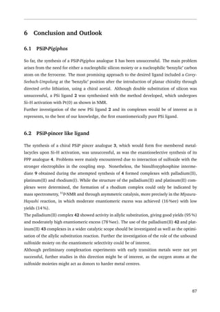
![6 Conclusion and Outlook
6.3 Biferrocenylsulfoxide and Biferrocenylsulfide
Bis(ferrocenylsulfoxide) (BiFeSO) 6 was synthesised successfully, giving two products with
same connectivity as indicated by NMR spectra. The two products 6a and 6b appear to be
atropisomers. In order to substantiate this conclusion, quantum chemical calculations were
performed to estimate the energy barrier to a conformational change from the fully charac-
terised BiFeSO 6b to the suggested structure 6a. The outcome of the calculations suggest that
a conformational change would not take place at rt. The calculated 1
H-NMR spectra of 6b and
those of 6a showed qualitative correspondence to the measured 1
H-NMR spectra, with regards
to the Cp protons. 6a showed peaks of acidic protons after work-up with aqueous solutions.
Although the counterion of the resulting compound could not be discerned, the acidic nature
of the protons was proven by deprotonation with NaOH, as well as by a deuterium–protium
exchange. Further investigation is needed in order to confirm the actual structure of 6a.
In a next step, 6b was reduced to give bis(ferrocenylsulfide) (BiFeS) 7. While BiFeSO 6b did
not undergo complexation with a large variety of transition metal precursors, BiFeS 7 seemed
to result in partial elimination of iso-butene, when treated with HgBr2. This reaction may be
further investigated. Also, a forced elimination of iso-butene iso-butene could be of interest in
order to produce bis(ferrocenylthiol), which might more readily undergo complexation.
6.4 Side Projects
6.4.1 Acidity of [Ni(II)-PigiphosL]2+
The synthesis of fluoro-Pigiphos-nickel(II) tetrafluoroborate 44 was developed. 19
F-NMR-
spectra revealed the paramagnetic nature of the complex, making it unsuitable for the in-
tended FIA estimation of the Ni(II)-Pigiphos system. As the approach failed, another experi-
mental set-up should be developed in order to enable an FIA estimation.
6.4.2 Ferrocenyl building block
A synthetic route towards bromostannylferrocene 9 and bromophosphinoferrocene 40 were
developed. While selective substitution of either the stannyl group or the bromine in 9 was
unsuccessful, the approach to an ‘inert’ building block in the form of 40 failed due to low
yields and purification problems.
During the course of this work, Zirakzadeh et al.[253]
reported a similar synthesis of com-
pound 9. They exchanged the stannyl group in a further step with iodine to use the resulting
88](https://image.slidesharecdn.com/17dafaa7-bb25-4952-a328-ce8054639453-151111071008-lva1-app6892/85/eth21627-108-320.jpg)
![6.5 General outlook
enantiomerically pure bromoiodoferrocene in Negishi coupling. The bromoiodoferrocene they
reported should be further exploited for its use in other palladium catalysed couplings, as the
selectivity of palladium towards iodine is enough to obtain highly enantiomerically enriched
products.
6.4.3 Ferrocenyl-(trifluoromethyl) sulfide
(Trifluoromethyl)ferrocenylsulfide 10 was synthesised from sodium ferrocenylsulfide 45, us-
ing the Togni acid reagent. Yields were low, as mainly the oxidation to ferrocenyldisulfide pre-
dominated. Other approaches using different trifluoromethylating agents or trifluoromethylth-
iolating agents should be investigated.
6.5 General outlook
In order to expand the asymmetric tridentate ligand concept, alternative designs, such as the
PSiP pincer-like ligand 31 reported by Turculet and co-workers,[132]
seem tenable. If the pe-
ripheral phosphines are substituted with a chiral substituent (e.g. (–)-menthyl) and an achiral
alkyl or aryl group, the resulting diastereomeric mixture should be separable. As a result an
enantiomerically enriched ligand could be obtained with stereoinformation at the phosphine
donors. An analogous process could lead to a PPP derivative, therefore enabling comparative
studies between the PSiP and PPP systems (cf. Scheme 65).
Si
P P
menth
R
R
menth
Me
H
P
P P
menth
R
R
menth
R'
Si
P PPh2
Me
HPh2
31
Scheme 65: Proposed chiral tridentate ligands, derived from Turculet’s PSiP ligand 31.
89](https://image.slidesharecdn.com/17dafaa7-bb25-4952-a328-ce8054639453-151111071008-lva1-app6892/85/eth21627-109-320.jpg)

![7 Experimental
7.1 General Remarks
7.1.1 Techniques
All reactions and manipulations involving air- or moisture-sensitive compounds were car-
ried out under an inert atmosphere of argon using standard Schlenk techniques[292]
or in a
glove box (MBraun MB 150B-G and Lab Master 130) under an atmosphere of dry nitrogen.
Glassware were preheated to 140 ◦
C in a drying oven or dried under HV with a heat gun
and then purged with argon. Dry solvents were freshly distilled under an argon atmosphere
over sodium/benzophenone (toluene, THF, diethyl ether), sodium/benzophenone/diglyme (n-
pentane), sodium/benzophenone/tetraglyme (n-hexane), sodium/diethyl phthalate (EtOH)
or calcium hydride (MeOH, CH2Cl2, CH3CN, toluene). Solvents used for synthetic and recrys-
tallisation purposes were of "puriss p.a." quality (Sigma-Aldrich, Riedel-de-Haen, J.T. Baker
or Merck) and were, if necessary, degassed by saturating with argon or by 3 freeze-pump-
thaw cycles. For flash chromatography and TLC, technical grade solvents were generally used.
Deuterated solvents were purchased from Cambridge Isotope Laboratories or Armar Chemi-
cals (CDCl3). For use with sensitive compounds they were purified by bulb-to-bulb distillation
from Na (C6D6) or CaH2 (CD2Cl2), degassed by 3 freeze-pump-thaw cycles and stored under
argon in a Young Schlenk tube.
7.1.2 Chemicals
Commercially available chemicals were purchased from ABCR, Acros AG, Sigma-Aldrich, TCI
or Pressure Chemical Co. and metal precursors from Johnson Matthey (Na2PdCl4, IrCl3 ·3 H2O)
and used without further purification. (S)-(–)-1,2,4-butanetriol was either purchased from
ABCR or synthesised from malic acid.[83]
(1R,2S,5R)-(–)-menthyl-(S)-p-toluenesulfinate was
purchased from TCI and recrystallised or synthesised from (–)-Menthol and sodium p-
toluenesulfinate.[293,294]
(R)-Ugi’s amine was kindly provided by Solvias AG (Basel) as a tar-
trate salt and was obtained as enantiomerically pure free amine following a modified version
of the procedure described by Ugi.[49]
If necessary the concentration of butyllithium reagents
was determined by titration against diphenyl ditelluride.[295]
91](https://image.slidesharecdn.com/17dafaa7-bb25-4952-a328-ce8054639453-151111071008-lva1-app6892/85/eth21627-111-320.jpg)
![7 Experimental
7.1.3 Analytical Techniques and Instruments
Thin layer chromatography (TLC) was performed on Merck Silica gel 60 (F254) visualized
by fluorescence quenching at 254 nm. In addition, permanganate (1 g KMnO4, 2 g NaCO3,
100 mL EtOH), vanillin (12 g vanillin, 2 mL H2SO4 conc., 200 mL EtOH) or iodine were used
as developing agents.
Flash column chromatography (FC) was performed on Fluka Silica Gel 60 (230-400 mesh)
using the given solvent ratios and a forced flow of eluent at 0.1 – 0.2 bar nitrogen overpres-
sure.
NMR spectra were recorded on Bruker 700 Avance, 500 DPX Avance, 400 DPX Avance, 300
DPX Avance, 300 Avance III HD Nanobay, 250 DPX Avance or 200 DPX Avance spectrometers
operating at the given spectrometer frequency. The samples were measured as solutions in the
given solvent at room temperature (if not indicated differently) and in non-spinning mode.
The chemical shifts (δ) are expressed in part per millions (ppm) relative to TMS as an exter-
nal standard for 1
H- and 13
C-NMR spectra analogously to IUPAC[296]
and are calibrated against
the residual solvent peak. For CD2Cl2 as solvent δ = 5.32 ppm and δ = 53.8 ppm were used
for the calibration of 1
H- and 13
C-NMR spectra respectively. The multiplicity, if the signals are
split, are described using the abbreviations: s, d, t, q and m for singlet, doublet, triplet, quartet
and multiplet respectively or by using combinations of the aforementioned abbreviations as
dd = doublet of doublet. The absolute values of the coupling constants J are given in Hertz
(Hz).
High-resolution mass spectra (HiRes-MS) were measured by the MS-Service of the "Labora-
torium für organische Chemie der ETHZ". The signals are given as mass per charge number
(m/z).
Elemental Analysis (EA) were carried out by the microelemental analysis service of the "Lab-
oratorium für organische Chemie der ETHZ" on a LECO CHN-900 analyzer. The content of the
specified element is expressed in mass percent (%).
High Pressure Liquid Chromatography (HPLC) was run on a Hewlett-Packard 1050 Series
or an Agilent 1100 Series respectively with detection at three different wave lengths (210,
230, 254 nm) using the specified column (Diacel Chiralcel OJ, OD-H or OB-H), flow rate of
the solvents (mL/min), ratio of n-hexane/i-PrOH and sample injection volume (µL; sample
concentration approximately 1 mg/mL). Retention times tR are given in minutes (min).
Crystallography: Intensity data of single crystals glued to a glass capillary were collected at
the given temperature (usually 100 K) on a Bruker SMART APEX platform with CCD detector
and graphite monochromated Mo Kα radiation (λ = 0.71073 Å). The program SMART served
for data collection; integration was performed with the software SAINT.[297]
The structures
92](https://image.slidesharecdn.com/17dafaa7-bb25-4952-a328-ce8054639453-151111071008-lva1-app6892/85/eth21627-112-320.jpg)
![7.2 Syntheses
were solved by direct or Patterson methods, using the program SHELXS 97.[298]
The refine-
ment and all further calculations were carried out using SHELXL 97.[299]
All non-hydrogen
atoms were refined anisotropically using weighted full-matrix least squares on F2
. The hydro-
gen atoms were included in calculated positions and treated as riding atoms using SHELXL
default parameters. An absorption correction was applied (SADABS)[300]
and weights were
optimized in the final refinement cycles. The absolute configuration of chiral compounds was
determined on the basis of the Flack parameter.[301,302]
The standard uncertainties (s.u.) are
rounded according to the "Notes for Authors" of Acta Crystallographica.[303]
7.2 Syntheses
7.2.1 Ligands and Complexes
Fe
H
OO
OH(2S,4S)-4-(Hydroxymethyl)-2-ferrocenyl-1,3-dioxane (18)[84]
C15H18FeO3, 302.15 g/mol
Ferrocenylcarbaldehyde (4.25 g, 19.9 mmol, 1 equiv) was dissolved
in 30 ml of trimethylorthoformate (274 mmol, 14 equiv) in a 100 ml
round bottom flask. A catalytic amount of p-toluenesulfonic acid
monohydrate (190 mg, 1 mmol, 5% mol equiv) was added turning
the solution from dark red to yellowish black. The reaction vessel was fitted with a drying
tube loaded with CaCl2 and the solution was stirred over night at 80 ◦
C. Anhydrous K2CO3
was added and the solution was allowed to cool to rt, while stirring was maintained. The
resulting suspension was diluted with diethyl ether and filtered through celite. The filter cake
was washed with diethyl ether until the filtrate was colourless. The filtrate was concentrated
in vacuo and dried under high vacuum over night. The crude product (5.16 g) was dissolved
in 10 ml of chloroform and 15 g of 4 Å activated molecular sieve were added. (S)-(–)-1,2,4-
Butanetriol (2.11 g, 19.9 mmol, 1 equiv) was dried by azeotropic distillation using toluene
(three times) and then dissolved in 30 ml of chloroform. Camphorsulfonic acid (230 mg,
0.99 mmol, 5% mol equiv) was added to the triol solution, which was subsequently mixed
with the crude acetal solution. The reaction vessel was fitted with a drying tube loaded with
CaCl2 and the mixture stirred over night at rt. K2CO3 was added and the resulting suspension
was filtered through celite and the filter cake washed with dichloromethane. The filtrate was
then concentrated in vacuo to yield the crude product, which was purified by flash column
chromatography (1:1 cyclohexane/ethyl acetate) and recrystallised from boiling toluene to
yield the desired product as yellow crystals.
Yield: 2.89 g, 48 %. 1
H-NMR (300 MHz, CDCl3): δ 5.40 (s, 1H, CHacetal), 4.32 (m, 2H,
93](https://image.slidesharecdn.com/17dafaa7-bb25-4952-a328-ce8054639453-151111071008-lva1-app6892/85/eth21627-113-320.jpg)
![7 Experimental
CHCp), 4.23 (m, 1H, OCH(CH2)2), 4.16 (s, 5H, CHCp ), 4.14 (m, 2H, CHCp), 3.93 (m, 2H,
OCH2CH2), 3.64 (s, 2H, CH2OH), 2.07 (m, 1H, OH), 1.83 (m, 1H, OCH2CHHaxCH), 1.39 (m,
1H, OCH2CHHeqCH). CAS-number: 149095-40-9
Fe
H
OO
O(2S,4S)-4-(Methoxymethyl)-2-ferrocenyl-1,3-dioxane (17)[84]
C16H20FeO3, 316.17 g/mol
The dioxane 18 (3.90 g, 12.9 mmol, 1 equiv) was dissolved in
30 ml of THF and added dropwise to a suspension of prewashed
NaH (463 mg, 19.3 mmol, 1.5 equiv) in 5 ml of THF at 0 ◦
C. Neat
iodomethane (1.3 ml, 2.95 g, 20.8 mmol, 1.6 equiv) was added and
the resulting reaction mixture allowed to warm to rt and stirred for 2 h. In order to destroy
excess NaH and iodomethane the reaction mixture was cooled to 0 ◦
C and methanol was
added slowly. After quenching with water all solvents were evaporated in vacuo and the
residue dissolved in dietyl ether (40 ml), washed twice with water (20 ml), once with brine
(20 ml) and dried over MgSO4. After filtration through silica (diethyl ether) and evaporation
of the solvent in vacuo the product was obtained in quantitative yield.
Yield: 3.35 g, 82 %. 1
H-NMR (300 MHz, CDCl3): δ 5.37 (s, 1H, CHacetal), 4.32 (m, 2H, CHCp),
4.23 (m, 1H, OCH(CH2)2), 4.16 (s, 5H, CHCp ), 4.12 (m, 2H, CHCp), 3.91 (m, 2H, OCH2CH2),
3.48 (s, 2H, CH2OMe), 3.42 (s, 3H, OCH3), 1.78 (m, 1H, OCH2CHHaxCH), 1.48 (m, 1H,
OCH2CHHeqCH). CAS-number: 149095-41-0
Fe
H
OO
O
PPh2
(2S,4S,SFc)-4-(Methoxymethyl)-2-[α-
(diphenylphosphino)ferrocenyl]-1,3-dioxane (24)[84]
C28H29FeO3P, 500.35 g/mol
The acetal 17 (0.970 g, 3.07 mmol, 1 equiv) was dissolved in dry
diethyl ether and cooled to –78 ◦
C. t-BuLi (1.78 ml, 1.9 M in
pentane, 3.37 mmol, 1.1 equiv) was added dropwise resulting in a
dark orange percipitate. After stirring at –78 ◦
C for 15 min the mixture was allowed to warm
to rt and stirred for another 2 h. After cooling the mixture to –25 ◦
C, using a o-xylene/dry
ice cooling bath, chlorodiphenylphosphine (0.67 ml, 0.83 g, 3.68 mmol, 1.2 equiv) was added
and the mixture stirred for another 30 min before warming it to rt and stirring it over night.
The reaction mixture was quenched with 2 M aqueous NaOH solution to get rid of remaining
chlorodiphenylphosphine and subsequently extracted with diethyl ether. Flash column
chromatography (9:1 cyclohexane/diethyl ether) on silica gel yielded the product as a brown
solid.
Yield: 1.26 g, 82 %. [α]D = –187° (c = 0.95, CHCl3). 1
H-NMR (300 MHz, CDCl3): δ
94](https://image.slidesharecdn.com/17dafaa7-bb25-4952-a328-ce8054639453-151111071008-lva1-app6892/85/eth21627-114-320.jpg)
![7.2 Syntheses
7.60 – 7.15 (m, 10H, CHarom), 5.66 (dd, JPH = 2.12 Hz, 1H, CHacetal), 4.68 (m, 1H, CHCp),
4.21 (m, 2H, CHCp and OCH(CH2)2), 4.06 (s, 5H, CHCp ), 3.91 (m, 1H, CHCp), 3.80-3.67 (m,
2H, CH2CH2OCH), 3.07 (s, 3H, CH3), 2.93 (d, JHH = 5.17 Hz, 2H, CHCH2OMe), 1.73 (m,1H,
OCH2CHHaxCH), 1.46 (m,1H, OCH2CHHeqCH). 31
P{1
H}-NMR (121.5 MHz, CDCl3): δ –21.1
(s, 1P, FcPPh2).
Fe
SS
2-Ferrocenyl-1,3-dithiane (29)[162]
C14H16FeS2, 304.25 g/mol
A 50 ml 2-neck round bottom flask was charged with Formylferrocene
(300 mg, 1.40 mmol, 1 equiv), 0.15 ml of 1,3-propanedithiol (0.16 g,
1.5 mmol, 1.05 equiv) and 10 ml of benzene and equipped with a gas inlet
tube. After cooling the solution to 0 ◦
C in situ generated HCl gas (by addition
of sulfuric acid to sodium chloride) was bubbled through for 4 h. The reaction mixture was
dilluted with an additional amount of 10 ml of benzene, washed with 1 M NaOH(aq.) and
brine and dried over MgSO4 before concentration in vacuo. Recrystallisation from benzene
yielded the pure product as orange crystals.
Yield: 305 mg, 72 %. 1
H-NMR (300 MHz, CDCl3): δ 4.87 (b, 1H, CHthioacetal), 4.23 (m, 2H,
CHCp), 4.15 (s, 5H, CHCp ), 4.05 (m, 2H, CHCp), 2.90 (m, 2H, SCHH), 2.74 (m, 2H, SCHH),
2.02 (m, 1H, CHH(CH2S)2), 1.77 (m, 1H, CHH(CH2S)2).
Fe
Si
SS
Cl
2-Ferrocenyl-2-[(chlorodimethyl)silyl]-1,3-dithiane (28)[162]
C16H21ClFeS2Si, 396.85 g/mol
A 20ml schlenk tube was charged with the thioacetal 29 (755 mg,
2.55 mmol, 1 equiv) and 5 ml of THF cooled to –30 ◦
C. n-BuLi (1.6 ml,
1.6 M in hexane, 2.6 mmol, 1 equiv) was added resulting in a colour
change of the dark yellow suspension to turn dark red-orange. After
stirring for 18 h dichlorodimethylsilane (0.16 ml, 0.17 g, 1.3 mmol, 0.5 equiv) was added
dropwise resulting in a darkening of the red solution. The reaction mixture was stirred for
another hour at –25 ◦
C and then cooled to –78 to isolate the precipitate by filtration. After
resublimation the product was obtained together with a small amount of starting material as
a yellow solid.
Yield: 100 mg, <10 %. 1
H-NMR (500 MHz, CDCl3): δ 4.40 (s, 5H, CHCp ), 4.29 (t,
JHH = 1.8 Hz, 2H, CHCpCCp,quat), 4.18 (t, JHH = 1.83 Hz, 2H, CHCpCHCp), 3.52 (ddd, JHH = 14.5,
95](https://image.slidesharecdn.com/17dafaa7-bb25-4952-a328-ce8054639453-151111071008-lva1-app6892/85/eth21627-115-320.jpg)
![7 Experimental
12.0, 2.7 Hz, 2H, SCHeqH), 2.77 (ddd, JHH = 14.5, 9.8, 3.5 Hz, 2H, SCHax H), 2.26 (m, 1H,
CH2CHax HCH2), 2.03 (m, 1H, CH2CHeqHCH2), 0.37 (s, 6H, SiCH3). 13
C{1
H}-NMR (126 MHz,
CDCl3): δ 90.9 (s, 1C, CCp,quat), 70.1 (s, 5C, CHCp ), 67.4 (s, 2C, CHCpCCp,quat), 67.3 (s, 2C,
CHCpCHCp), 38.4 (s, 1C, CCpC(S2)Si), 27.4 (s, 2C, SCH2CH2), 25.7 (s, 1C, CH2CH2CH2), 1.95
(s, 6C, SiCH3). 29
Si-INEPT-NMR (59.6 MHz, CDCl3): δ 23.9 (s, 1Si).
Fe
H
SS
PPh2
(SFc)-2-[α-(Diphenylphosphino)ferrocenyl]-1,3-dithiane (25)[162]
C26H25FePS2, 488.42 g/mol
A 100 ml 2-neck round bottom flask was equipped with a gas inlet tube
and charged with the phosphinoacetal 24 (1.26 g, 2.52 mmol, 1 equiv),
0.27 ml of 1,3-propanedithiol (0.29 g, 2.7 mmol, 1.05 equiv) and 20 ml of
benzene. The solution was cooled to 0 ◦
C and in situ generated (by addition
of Sulfuric acid to sodium chloride) HCl gas was bubbled through the solution resulting in
the formation of a slight percipitate. Stirring and addition of HCl was continued for another
4 h, before diluting the reaction mixture with an additional 20 ml of benzene. After washing
the solution with 1 M NaOH(aq.) and brine the organic layer was separated and dried
over magnesium sulfate and concentrated in vacuo. After recrystallisation from benzene the
product was obtained as brown crystals.
Yield: 500 mg, 41 %. 1
H-NMR (300 MHz, CDCl3): δ 7.61 (m, 2H, CHortho), 7.40 (m,
2H, CHortho), 7.38 (m, 1H, CHpara), 7.20 (m, 4H, CHmeta), 7.16 (m, 1H, CHpara), 5.26 (d,
JPH = 4.5 Hz, 1H, SCHS), 4.67 (m, 1H, PCCp,quatCHCp), 4.38 (m, 1H, CHCpCHCpCHCp), 4.05
(s, 5H, CHCp ), 3.98 (m, 1H, (S2CH)CCp,quatCHCp), 3.05 (ddd, JHH
= 11.9, 9.9, 2.41 Hz, 1H,
), 2.92 (m, 2H, ), 2.58 (dm, JHH
= 13.9 Hz, 1H, ), 2.06 (dm, JHH
= 13.9 Hz, 1H, ), 1.78
(qm, JHH
= 12.9 Hz, 1H, ). 31
P{ 1
H}-NMR (121.5 MHz, CDCl3): δ –24.2 (s, 1P). HRMS
(Dual MALDI/ESI): m/z calcd for C26H25FePS2: 488.0479, found: 488.0479 [M]+
. Mp:
167.5 – 169 ◦
C.
Fe
Si
SS
PPh2 Cl
(SFc)-2-[α-(Diphenylphosphino)ferrocenyl]-2-
[(chlorodimethyl)silyl]-1,3-dithiane (30)[162]
C28H30ClFePS2Si, 581.02 g/mol
The thioacetal 25 (100 mg, 0.205 mmol, 1 equiv) was dissolved in 2 ml of
dry THF in a 20 ml schlenk tube and cooled to –78 ◦
C. n-BuLi (0.13 ml,
1.6 M in hexane, 0.21 mmol, 1 equiv) was added to the reaction mixture
96](https://image.slidesharecdn.com/17dafaa7-bb25-4952-a328-ce8054639453-151111071008-lva1-app6892/85/eth21627-116-320.jpg)
![7.2 Syntheses
and stirring continued for another 10 min before allowing the reaction mixture to warm to
rt resulting in a colour change from yellowish brown to deep red. Stirring was continued
at rt for another 20 min before cooling to –78 ◦
C and adding dichlorodimethylsilane (25 µl,
26 mg, 0.21 mmol, 1 equiv) is added to the reaction mixture. After 5 min of stirring the
reaction mixture started to lose its deep red colour turning into a yellowish black solution.
The solution was allowed to warm to rt and stirred for another 15 min before the addition of
3 ml of water. After extraction with chloroform the combined organic layers where washed
with water and brine, dried over MgSO4 and concentrated in vacuo. The crude product was
filtered through a column of silica gel (1:1, ether/pentane) collecting the coloured fractions.
After a flash column chromatography over silica gel (1:4, ether/pentane) the product was
obtained as a yellow solid from the second fraction with a slight impurity of starting material.
Yield: 20 mg, <16 %. 1
H-NMR (300 MHz, CD2Cl2): δ 7.66 (m, 2H, CHPh), 7.37 (m, 4H,
CHPh), 7.32 (m, 2H, CHPh), 7.20 (m, 4H, CHPh), 4.69 (m, 1H, CHCp), 4.47 (m, 1H, CHCp),
4.27 (m, 1H, CHCp), 3.97 (s, 5H, CHCp ), 3.00 (m, 1H, CHH), 2.72 (m, 1H, CHH), 2.27
(m, 2H, CHH), 1.90 (m, 2H, CHH), 0.48 (s, 3H, SiCH3) 0.38 (s, 3H, SiCH3). 31
P{1
H}-NMR
(101.3 MHz, CDCl3): δ –22.4 (s, 1P). 29
Si{1
H}-NMR (59.6 MHz, CDCl3): δ 9.9 (s, 1Si).
Fe
Si
SS
PPh2 H
(SFc)-2-[α-(Diphenylphosphino)ferrocenyl]-2-[(dimethyl)silyl]-1,3-
dithiane (2)[162]
C28H31FePS2Si, 546.58 g/mol
A 50 ml schlenk tube was charged with thioacetal 25 (250 mg,
0.513 mmol, 1 equiv) and 5 ml of THF and cooled to –78 ◦
C before
addition of n-BuLi (0.36 ml, 1.6 M in hexane, 0.58 mmol, 1.1 equiv).
After 15 min of stirring the reaction mixture was allowed to warm to rt and stirred at rt
for 30 min resulting in a deep red coloured reaction mixture, which was then cooled back
to –78 ◦
C for the addition of chlorodimethylsilane (70 µl, 60 mg, 0.63 mmol, 1.2 equiv).
After stirring for 45 min the mixture was allowed to warm to rt and concentrated in vacuo.
Flash column chromatography over silica gel (15 g) using 10:1 pentane/diethyl ether and
evaporation of the solvents yielded the product as an orange foam.
Yield: 230 mg, 82 %. 1
H-NMR (300 MHz, CD2Cl2): δ 7.60 (m, 2H, CHortho), 7.41 (m,
1H, CHpara), 7.37 (m, 2H, CHortho), 7.19 (m, 4H, CHmeta), 7.14 (m, 1H, CHpara), 4.60
(m, 1H, PCCp,quatCHCp), 4.56 (m, 1H, SiH), 4.39 (m, 1H, CHCpCHCpCHCp), 4.09 (m, 1H,
(S2Si)CCCp,quatCHCp), 3.98 (s, 5H, CHCp ), 2.96 (m, 2H, SCHeqH), 2.79 (m, 1H, SCHax H),
2.65 (m, 1H, SCHax H), 2.02 (m, 1H, CH2CHeqHCH2), 1.95 (m, 1H, CH2CHaxHCH2), 0.26
(d, JHH = 3.7 Hz, 3H, SiCH3) 0.14 (d, JHH = 3.7 Hz, 3H, SiCH3). 13
C{1
H}-NMR (75.5 MHz,
97](https://image.slidesharecdn.com/17dafaa7-bb25-4952-a328-ce8054639453-151111071008-lva1-app6892/85/eth21627-117-320.jpg)
![7 Experimental
CD2Cl2): δ 142.2 (s, 2C, Cphenyl,quat) 135.8 (s, 2C, CHortho), 132.8 (s, 1C, CHpara), 129.0
(s, 1C, CHpara), 128.1 (s, 2C, CHortho), 127.7 (s, 4C, CHmeta), 96.6 (s, 1C, CCp,quat), 73.8
(s, 1C,(S2Si)CCCp,quatCHCp), 71.6 (s, 1C, PCCp,quatCHCp), 70.7 (s, 5C, CHCp ), 68.9 (s, 1C,
CHCpCHCpCHCp), 38.6 (s, 1C, CCpC(S2)Si), 28.2 (s, 1C, SCH2CH2), 28.0 (s, 1C, SCH2CH2),
25.4 (s, 1C, CH2CH2CH2), –3.9 (s, 1C, SiCH3), –3.6 (s, 1C, SiCH3). 31
P{1
H}-NMR (121.5 MHz,
CDCl3): δ –22.3 (s, 1P). 29
Si-INEPT-NMR (99.4 MHz, CDCl3): δ –13.9 (s, 1Si). HRMS (Dual
MALDI/ESI): m/z calcd for C28H31FePS2Si: 546.0718, found: 546.0715 [M]+
. Mp: 108 ◦
C,
203 ◦
C (decomp).
Fe
Si
S S
P Pt
Ph2 PPh3
H
[κ2
-((SFc)-2-[α-(Diphenylphosphino)ferrocenyl]-
2-[(dimethyl)silylo]-1,3-dithiane)(hydrido)-
(triphenylphosphino)platinum(II)] (46)[162]
C46H46FeP2PtS2Si, 1003.96 g/mol
A Young NMR tube was charged with phosphino-silane 2 (22.1 mg,
40.6 µmol, 1 equiv) and tetrakis-(triphenylphosphine)platinum(0)
(50.5 mg, 40.6 µmol, 1 equiv) and thoroughly purged with argon. 6.0 ml of d6-benzene were
added and the reactants were suspended therein using the sonic bath. After 6 h at rt, while
the sample has been agitated every 30 min, a white precipitate has formed and NMR showed
the formation of a hydride in the yellow-red solution.
Yield: not isolated. 1
H-NMR (400 MHz, C6D6): δ 7.63 (m, 2H, CHphenyl on 2) 7.55 (m, 6H,
CHphenyl on PPh3), 7.22 (m, 2H, CHphenyl on 2), 6.92 (m, 4H, CHphenyl on 2), 6.87 (m, 9H,
CHphenyl on PPh3), 6.76 (td, JHH = 7.7, 1.9 Hz, 2H, CHphenyl on 2), 4.88 (m, 1H, CHCp), 4.22
(m, 1H, CHCp), 4.21 (s, 5H, CHCp ), 3.68 (m, 1H, CHCp), 3.08 (ddd, JHH = 13.4, 11.9, 3.9 Hz,
1H, CHH), 2.37 (m, 2H, CHH and CHH), 1.77 (m, 1H, CHH), 1.68 (m, 1H, CHH), 1.52
(m, 1H, CHH), 1.48 (s with Pt satellites, JPtH = 40 Hz, 3H, SiCH3), 1.43 (s with Pt satellites,
JPtH = 40 Hz, 3H, SiCH3), –1.07 (dd with Pt satellites, JPH = 155, 25 Hz, JPtH = 1065 Hz, 1H,
PtH). 13
C{1
H}-NMR (75.5 MHz, C6D6): δ (phenyl carbon atoms were not assigned) 105.6
(s, 1C, CCp,quat), 74.0 (s, 1C, CHCp), 71.4 (s, 1C, CHCp), 70.9 (s, 5C, CHCp ), 70.7 (s, 1C,
CHCp), 67.3 (s, 1C, CCp), 36.4 (s, 1C, Cquat(S)2), 28.0 (s, 1C, CH2), 25.1 (s, 1C, CH2), 23.9 (s,
1C, CH2), 11.1 (s, 1C, SiCH3) 6.9 (s, 1C, SiCH3) INCOMPLETE. 31
P{1
H}-NMR (121.5 MHz,
CDCl3): δ 30.4 (d with Pt satellites, JPP = 15.7 Hz, JPtP = 1560 Hz, 1P, PPh3), 14.1 (d with
Pt satellites, JPP = 15.7 Hz, JPtP = 2487 Hz, 1P, PFcPh2). 29
Si-INEPT-NMR (99.4 MHz, CDCl3):
δ 15.5 (m with Pt satellites, JPtSi = 1114 Hz, 1Si). 195
Pt-INEPT-NMR (53.8 MHz, CDCl3): δ
–5204.
98](https://image.slidesharecdn.com/17dafaa7-bb25-4952-a328-ce8054639453-151111071008-lva1-app6892/85/eth21627-118-320.jpg)
![7.2 Syntheses
Fe
S
O(S)-Ferrocenyl p-tolyl sulfoxide (16)[69,84]
C17H16FeOS, 324.22 g/mol
A dry 500 ml two neck round bottom flask was charged with
ferrocene (31.3 g, 168 mmol, 2 equiv) and t-BuOK (477 mg,
4.25 mmol, 0.1 equiv) under argon. 330 ml of THF were added
and the resulting solution cooled to –78 ◦
C. t-BuLi (42 ml, 1.9 M in pentane, 79.8 mmol,
0.95 equiv) was added dropwise over a time period of 30 min. Stirring was continued at
–78 ◦
Cfor another 30 min before allowing the reaction mixture to warm to rt and further
stirring for another 30 min. Using a o-xylene/dry ice cooling bath, the suspension in the
reaction vessel was cooled to approximately -25 ◦
C and added to a precooled solution (-25 ◦
C)
of (-)-(1R)-menthyl (S)-p-toluenesulfinate in 170 ml THF through a thick canula. After stirring
was continued for another 20 min, the reaction was quenched by addition of 60 ml of water
and allowed to warm to rt. After extraction with ether and washing twice with water, once
with brine the organic layer was dried over MgSO4 filtered an concentrated in vacuo. The raw
product was purified by flash column chromatography over 350 g of silica gel. First ferrocene
and menthol were washed out using 1:1 diethyl ether/hexane. By changing the eluent to 4:1
diethyl ether/DCM the product could be washed from the column in a second fraction. After
concentration in vacuo the product was dissolved in a minimal amount of DCM/diethylether
3:7 (around 80 ml) and covered with a layer of hexane (40 ml) for crystallisation over two
days. A first fraction crystals where recovered by decanting the mother liquor. The remaining
solution was covered with another layer of hexane (20 ml) to yield a second crop of crystals
over night. The two fractions of crystals where dissolved in a minimal amount of DCM and
precipitated with n-pentane to yield the pure product as a yellow powder by filtration.
Yield: 12 g, 46 %. 1
H-NMR (300 MHz, CDCl3): δ 7.52 (d, JHH = 7.9 Hz, 2H, CHarom), 7.25 (d,
JHH = 7.9 Hz, 2H, CHarom), 4.61 (m, 1H, CHCp), 4.37 (s, 5H, CHCp ), 4.36 (m, 2H, CHCp), 4.32
(m, 1H, CHCp), 2.37 (s, 3H, CH3). CAS-number: 164297-25-0
Fe
S
O(R)-Ferrocenyl t-butyl sulfoxide (15)[78]
C14H18FeOS, 290.20 g/mol
A 1 l round bottom schlenk flask was charged with ferrocene (20.0 g,
108 mmol, 2 equiv), t-BuOK (605 mg, 5.44 mmol, 0.1 equiv) and THF
(300 ml) and cooled to –78 ◦
C. Addition of t-BuLi (27 ml, 1.9 M in pen-
tane, 0.95 equiv) led to an orange suspension. The reaction mixture was stirred at –78 ◦
C for
about 1 h and then allowed to warm to rt and stirred for about 30 min. Meanwhile a solution
of (R)-bis-t-butyl thiosulfinate (10.4 g, 53.8 mmol, 1 equiv) in THF (150 ml) was prepared
99](https://image.slidesharecdn.com/17dafaa7-bb25-4952-a328-ce8054639453-151111071008-lva1-app6892/85/eth21627-119-320.jpg)
![7 Experimental
in a second 1 l round bottom schlenk flask and cooled to –78 ◦
C. The ferrocenyl lithium
suspension was cooled to –78 ◦
C and transferred to the thiosulfinate solution using a thick
cannula resulting in a dark red coloured solution. After allowing the solution to warm to
rt and further stirring for 30 min it was quenched with water and extracted with diethyl
ether, washed with water and brine and dried over MgSO4, before concentration in vacuo to
yield the crude product as a yellow powder. Purification by flash column chromatography
yielded the unreacted ferrocene in a first yellow fraction which was eluted with 1:1 diethyl
ether/hexane. After changing the eluent to 4:1 diethyl ether/DCM the product was eluted
in a second orange fraction which after concentration in vacuo yielded the pure product as a
orange solid foam.
Yield: 7.28 g, 47 %. 1
H-NMR (300 MHz, CD2Cl2): δ 4.62 (m, 1H, CHCp), 4.40 (m, 1H,
CHCp), 4.38 (m, 1H, CHCp), 4.34 (m, 1H, CHCp), 4.33 (s, 5H, CHCp ), 1.06 (s, 9H, C(CH3)3).
CAS-number: 180293-25-8
Fe
S
O(rac)-Ferrocenyl iso-propyl sulfoxide (47)[78]
C13H16FeOS, 276.18 g/mol
Ferrocene (4.68 g, 25.2 mmol, 2 equiv) and t-BuOK (141 mg, 1.26 mmol,
0.1 equiv) were put in a 500 ml round bottom schlenk flask and thoroughly
purged with argon. After adding 60 ml of THF the solution was cooled
to –78 ◦
C resulting in an orange suspension. t-BuLi (7.9 ml, 1.6 M in pentane, 1 equiv) was
added and the reaction mixture stirred for 30 min before allowing it to warm to rt. While
stirring at rt was prolonged for 30 min, a solution of (R)-bis-iso-propyl thiosulfinate (2.00 g,
12.6 mmol, 1 equiv, 28 %ee) in THF (30 ml) was prepared in a separate 1 l round bottom
schlenk flask and cooled to –78 ◦
C. The ferrocenyllithium suspension was cooled to –25 ◦
C
using a o-xylene/dry ice bath and transferred via a cannula to the thiosulfinate solution
during 15 min. Stirring was prolonged for another 15 min at –78 ◦
C before allowing the
reaction mixture to warm to rt to be stirred for another 30 min before quenching by addition
of water (35 ml). The product was extracted with 60 ml of diethyl ether and the organic layer
washed once with water (30 ml) and twice with brine (30 ml) before drying over MgSO4. The
product was purified by flash column chromatography on silica gel (180 g) using 1:1 diethyl
ether/hexane as an eluent to elute a first coloured fraction containing ferrocene followed by a
4:1 mixture of diethyl ether/DCM to elute the product in a second fraction. The product was
recrystallised from hexane/diethyl ether/DCM 5:2:2 to give the racemic product as yellow
needles.
Yield: 1.29 g, 37 %. 1
H-NMR (300 MHz, CDCl3): δ 4.69 (m, 1H, CHCp), 4.40 (m, 2H, CHCp),
100](https://image.slidesharecdn.com/17dafaa7-bb25-4952-a328-ce8054639453-151111071008-lva1-app6892/85/eth21627-120-320.jpg)
![7.2 Syntheses
4.37 (m, 5H, CHCp ), 4.35 (m, 1H, CHCp), 2.76 (sept, JHH = 6.8 Hz, 1H, CH(CH3)2), 1.17 (d,
JHH = 6.8 Hz, 3H, CH3), 1.09 (d, JHH = 6.8 Hz, 3H, CH3). HRMS (Dual MALDI/ESI): m/z
calcd for C13H16FeOS: 276.0266, found 276.0266 [M]+
.
Fe
S-
Na+
Sodium ferrocenylsulfide (45)
C10H9FeNaS, 240.08 g/mol
A 100 ml Schlenk tube was charged with ferrocenylthiol (1.00 g,
4.59 mmol, 1.0 equiv), synthesised according to the literature,[304]
and
THF (30 ml). The resulting solution was cooled to –78 ◦
C and sodium hydride (0.12 g,
5.05 mmol, 1.1 equiv) was added in small portions resulting in a colour change from orange
to green. Stirring was continued, while the reaction mixture was allowed to warm to rt over
night. The resulting orange suspension was cooled to –78 ◦
C before n-pentane (30 ml) was
added and the suspension was filtered to receive the desired product as an orange powder.
Yield: 0.94 g, 85 %. 1
H-NMR (300 MHz, (CD3)2CO): δ 4.32 (t, JHH = 1.84 Hz, 2H, CHCp),
4.25 (t, JHH = 1.84 Hz, 2H, CHCp), 4.14 (s, 5H, CHCp ).
Fe
S CF3
(Trifluoromethyl)ferrocenylsulfide (10)
C11H9F3FeS, 286.09 g/mol
A 100 ml Schlenk tube was charged with sodium ferrocenylsulfide
(0.50 g, 2.08 mmol, 1.0 equiv) and DCM (20 ml). The resulting solution
was cooled to –78 ◦
C and 1-(trifluoromethyl)-1,2-benziodoxol-3-(1H)-one (0.56 g, 1.74 mmol,
1.01 equiv) was added in portions resulting in a colour change from bright yellow to a
greenish yellow. The reaction mixture was stirred over night and allowed to warm to rt
resulting before quenching with water (10 ml). The product was extracted with n-pentane
and the combined organic layers washed with water and brine and dried over MgSO4, before
concentration in vacuo. Flash column chromatography over silica with n-pentane/DCM (5:2)
and concentration in vacuo yielded the product as orange microcrystals.
Yield: 60 mg, 12 %. 1
H-NMR (700 MHz, (CDCl3): δ 4.47 (t, JHH = 1.9 Hz, 2H, CHCpCHCS),
4.37 (t, JHH = 1.9 Hz, 2H, CHCHCpCS), 4.23 (s, 5H, CHCp . 13
C{1
H}-NMR (176 MHz, CDCl3):
δ 75.6 (s, 2C, CHCpCHCS), 71.1 (s,2C, CHCHCpCS), 69.7 (s, 5C, CHCp ), 67.1 (s, 1C,
CHCCp,quatS). 19
F-NMR (188 MHz, CDCl3): δ –45.6 (s, 3F). HRMS (Dual MALDI/ESI): m/z
calcd for C11H9F3FeS: 285.9726, found: 285.9730 [M+
].
101](https://image.slidesharecdn.com/17dafaa7-bb25-4952-a328-ce8054639453-151111071008-lva1-app6892/85/eth21627-121-320.jpg)
![7 Experimental
Fe
Ph
P
Fe
SS
p-tol
O
p-tol
O
(SFc,SFc,SS,SS)-Bis-[2-(p-tolylsulfinyl)ferrocenyl]phenylphosphine
(5)
C40H35Fe2O2PS2, 754.50 g/mol
Diisopropylamine (5.4 ml, 3.9 g, 38 mmol, 2.2 equiv) was dissolved in
20 ml of dry THF in a 100 ml schlenk tube. The solution was cooled
to –78 ◦
C, 26 ml of n-BuLi (1.6 M in hexane, 42 mmol, 2.4 equiv) were
added through a canula and the resulting reaction mixture stirred
for 45 min at –78 ◦
C. Meanwhile, a 1 l schlenk flask was charged with ferrocenyl sulfoxide 16
(10.3 g, 31.8 mmol, 1.8 equiv) and 200 ml of dry THF and cooled to –78 ◦
C. The ready LDA
solution is now added to the ferrocenyl sulfoxide 16 solution resulting in a colour change
from brown to deep red. After stirring for 1 h at -78 ◦
C dichlorophenylphosphine (2.4 ml,
3.2 g, 18 mmol, 1 equiv) to the now orange suspension. Stirring was continued at –78 ◦
C for
2 h before quenching the reaction mixture with 1 M aqueous NaOH. The aqueous layer was
separated and the organic layer washed with water and brine and dried over MgSO4. The
raw product was adsorbed on silica gel and purified by flash column chromatography. First
two minor yellow fractions where washed out using 2:1:1 diethyl ether/hexane/DCM as an
eluent. After changing the eluent to 1:1 diethyl ether/DCM two more fractions eluted, with
the last containing the desired product. After the solution was evaporated to dryness the
product was obtained as a brown powder.
Yield: 4.7 g, 39 %. 1
H-NMR (300 MHz, CDCl3): δ 8.01 (d, JHH = 8.3 Hz, 2H, CHPh,ortho),
7.58 (td, JHH = 8.3, 1.5 Hz, 2H, CHPh,ortho), 7.43 (d, JHH = 8.3 Hz, 2H, CHPh,meta), 7.34 (d,
JHH = 8.3 Hz, 2H, CHPh,ortho), 7.29 (dm, JHH = 5.6 Hz, 1H, CHPh,para), 7.23 (dm, JHH = 7.8 Hz,
2H, CHPh,meta), 7.08 (dm, JHH = 8.3 Hz, 2H, CHPh,meta), 4.55 (m, 1H, CHCp), 4.49 (tm,
JHH = 2.2 Hz, 1H, CHCp), 4.41 (m, 2H, CHCp), 4.34 (s, 1H, CHCp), 4.33 (s, 5H, CHCp ), 4.23
(m, 1H, CHCp), 3.51 (s, 5H, CHCp ), 2.49 (s, 3H, CH3), 2.35 (s, 3H, CH3). 13
C-NMR (126 MHz,
CDCl3): δ 142.8, 142.1, 141.9, 140.5, 139.2, 135.1, 134.9, 129.9, 129.6, 128.3 126.3, 125.0,
102.9, 96.3, 81.7, 80.0, 74.4, 74.1, 72.6, 72.1, 71.5, 71.1, 70.3, 69.0, 22.0, 21.8. 31
P-NMR
(162 MHz, CD2Cl2): δ –43.2. HRMS (Dual MALDI/ESI): m/z calcd for C40H35Fe2NaO2PS2:
777.0408, found: 777.0394 [M + Na]+
.
102](https://image.slidesharecdn.com/17dafaa7-bb25-4952-a328-ce8054639453-151111071008-lva1-app6892/85/eth21627-122-320.jpg)
![7.2 Syntheses
Fe
Si
H
Fe
SS
p-tol
O
p-tol
O
Me
(SFc,SFc,SS,SS)-Bis-[2-(p-tolylsulfinyl)ferrocenyl]methylsilane
(34)
C35H34Fe2O2S2Si, 690.55 g/mol
LDA was freshly prepared by dissolving diisopropylamine (0.66 ml,
0.48 g, 4.7 mmol, 2 equiv) in 2 ml of dry THF at –78 ◦
C followed
by the addition of 3.2 ml of n-BuLi (1.6 M in hexane, 5.2 mmol,
2.2 equiv) and subsequent stirring for 30 min. The LDA solution was
then added dropwise to a stirred yellow suspension of the ferrocenylsulfoxide 16 (1.51 g,
4.67 mmol, 1 equiv) in 23 ml of THF in a 100 ml schlenk tube. After stirring for an hour
dichloromethylsilane (0.24 ml, ) was added to the reaction mixture resulting in a colour
change from deep orange to yellowish brown. Stirring was prolonged for another hour at
–78 ◦
C, before allowing the reaction mixture to warm to rt and quenching with 12 ml of
NaOH(aq.). After extraction with diethyl ether, the organic layer was washed thrice with
water and once with brine, dried over MgSO4 and concentrated in vacuo. Flash column
chromatography with 7:3 n-hexane/diethyl ether eluted first the remaining starting material
and side products. A change of the eluent to 4:1 diethyl ether/DCM yielded the desired
product after concentration in vacuo as a yellow powder.
Yield: 0.53 g, 33 %. 1
H-NMR (700 MHz, CDCl3): δ 7.58 (d, JHH = 14.7 Hz, 2H, CHtolyl), 7.57
(d, JHH = 14.7 Hz, 2H, CHtolyl) 7.24 (t, JHH = 8.9 Hz, 4H, CHtolyl), 5.30 (q, JHH = 3.8 Hz, 1H,
SiH), 4.54 (m, 1H, CHCp), 4.49 (m, 1H, CHCp), 4.44 (m, 1H, CHCp), 4.40 (m, 1H, CHCp),
4.32 (s, 5H, CHCp ), 4.28 (m, 1H, CHCp), 4.27 (s, 5H, CHCp ), 2.42 (s, 3H, CH3), 2.41 (s, 3H,
CH3), 1.10 (d, JHH = 3.8 Hz, 3H, SiCH3). 13
C{1
H}-NMR (176 MHz, CDCl3): δ 142.2 (s, 1C
Ctolyl,quatS), 141.4 (s, 1C Ctolyl,quatS), 141.0 (s, 1C Ctolyl,quatMe), 140.9 (s, 1C Ctolyl,quatMe), 129.3
(s, 4C, CHtolyl), 125.6 (s, 4C, CHtolyl), 98.4 (s, 1C, CCp,quat), 97.9 (s, 1C, CCp,quat), 79.9 (s, 1C,
CHCp), 78.1 (s, 1C, CHCp), 72.6 (s, 1C, CHCp), 72.5 (s, 1C, CHCp), 70.9 (s, 1C, CHCp), 70.5 (s,
1C, CHCp) 70.3 (s, 5C, CHCp ), 70.2 (s, 5C, CHCp ), 69.6 (s, 1C, CCp,quat), 69.4 (s, 1C, CCp,quat),
21.4 (s, 1C, (CH)2CCH3), 21.3 (s, 1C, (CH)2CCH3), –2.05 (s, 1C, SiCH3). 29
Si{1
H}-NMR
(60 MHz, CDCl3): δ –21.5 (s, 1Si). MS (ESI): m/z calcd for C35H34Fe2O2S2Si: 690.05, found:
689.04 (100 %), 690.04 (47 %), 691.05 (23 %) [M – H]+
.
103](https://image.slidesharecdn.com/17dafaa7-bb25-4952-a328-ce8054639453-151111071008-lva1-app6892/85/eth21627-123-320.jpg)
![7 Experimental
Fe
Pt SCl
O
P
Fe
SO
Cl
Di-κ1
-chloro(κ2
-(SFc,SFc,SS,SS)-Bis-
[2-(p-tolylsulfinyl)ferrocenyl]-
phenylphosphine)platinum(II) (43)
C40H35Cl2Fe2O2PPtS2, 1020.49 g/mol
A 50 ml Schlenk tube was charged with dichloro-1,5-
cyclooctadieneplatinum(II) (162 mg, 0.433 mmol,
1 equiv), sulfoxophosphine ligand 5 (327 mg,
0.433 mmol, 1 equiv) and DCM (20 ml) and the re-
sulting reaction mixture was stirred over night at rt. Then
the solvent was reduced reduced in vacuo to give about 5 ml of solution, which was covered
with a layer of n-hexane in order to precipitate the product as a dark yellow powder.
Yield: 0.37 mg, 83 %. 1
H-NMR (400 MHz, CD2Cl2): δ 8.46 (d, JHH = 8.0 Hz, 2H,
S(1)CCHarom), 8.22 (dm, JPH = 13.8 Hz, 2H, PCCHPh), 8.04 (d, JHH = 8.5 Hz, 2H,
S(2)CCHarom), 7.70 (m, 2H, CHPh,meta), 7.70 (m, 1H, CHPh,para), 7.62 (d, JHH = 8.0 Hz,
2H, S(1)CCHCHarom), 7.42 (d, JHH = 8.5 Hz, 2H, S(2)CCHCHarom), 5.26 (m, 1H, CHCp on
Fe(1)), 4.85 (m, 1H, CHC p on Fe(1)), 4.77 (m, 1H, CHCp on Fe(2)), 4.70 (m, 1H, CHCHCpCH
on Fe(2)), 4.53 (m, 1H, CHCHCpCH on Fe(1)), 4.36 (m, 1H, CHCp on Fe(1)), 4.36 (s, 5H,
CHCp on Fe(2)), 3.45 (s, 5H, CHCp on Fe(1)), 2.59 (s, 3H, S(1)(C6H4)CH3), 2.47 (s, 3H,
S(2)(C6H4)CH3) (for labeling cf. Chapter 3.4). 13
C{1
H}-NMR (100 MHz, CD2Cl2): δ 145.5
(s, 1C, S(1)Carom,quat), 142.2 (s, 1C, CH3CCH2CH2CS(2)), 141.9 (s, 1C, S(2)Carom,quat), 139.3
(s, 1C, CH3CCH2CH2CS(1)), 133.1 (s, 2C, PCCH), 129.9 (s, 2C, S(1)CCHCH), 129.7 (s, 2C,
PCCHCH), 129.6 (s, 2C, S(2)CCHCH), 129.1 (s, 1C, PCCHCHCH), 127.8 (s, 2C, S(1)CCH),
125.9 (s, 2C, S(2)CCH), 100.8 (s, 1C, CCp,quat on Fe(2)), 81.7 (s, 1C, CCp,quat on Fe(1)), 82.0
(s, 1C, CHCp on Fe(1)), 76.4 (s, 1C, CHCp on Fe(2)), 72.7 (s, 1C, CHCHCpCH on Fe(2)), 71.0
(s, 1C, CHCp on Fe(2)), 68.5 (s, 1C, CHCp on Fe(1)), 65.6 (s, 1C, CHCp on Fe(1)), 21.9 (s,
1C, S(1)(C6H4)CCH3), 21.6 (s, 1C, S(2)(C6H4)CCH3. 31
P{1
H}-NMR (162 MHz, CD2Cl2): δ
21.06 HRMS (MALDI): m/z calcd for C40H35Cl2Fe2NaO2PPtS2: 1041.9439, found: 1041.9436
[M + Na]+
.
104](https://image.slidesharecdn.com/17dafaa7-bb25-4952-a328-ce8054639453-151111071008-lva1-app6892/85/eth21627-124-320.jpg)
![7.2 Syntheses
Fe
Pd SCl
O
P
Fe
SO
Cl
Di-κ1
-chloro(κ2
-(SFc,SFc,SS,SS)-Bis-
[2-(p-tolylsulfinyl)ferrocenyl]-
phenylphosphine)palladium(II) (42)
C40H35Cl2Fe2O2PPdS2, 931.82 g/mol
A 50 ml Schlenk tube was charged with dichloro-1,5-
cyclooctadienepalladium(II) (182 mg, 0.636 mmol,
1 equiv), sulfoxophosphine ligand 5 (499 mg,
0.661 mmol, 1.05 equiv) and THF (20 ml) and the
resulting reaction mixture was stirred for 24 h at rt. The
solution was filtered and concentrated to dryness in vacuo to give a yellow powder, which was
redissolved in a minimal amount of THF and the resuling solution was covered with a layer
of n-hexane to precipitate the desired product.
Yield: 462 mg, 78 %. 1
H-NMR (400 MHz, CDCl3): δ 8.42 (d, JHH = 7.5 Hz, 2H, S(1)CCHarom),
8.22 (dm, JPH = 10.3 Hz, 2H, PCCHPh), 8.07 (d, JHH = 7.7 Hz, 2H, S(2)CCHarom), 7.65 (m,
2H, CHPh,meta), 7.65 (m, 1H, CHPh,para), 7.53 (d, JHH = 7.5 Hz, 2H, S(1)CCHCHarom), 7.32
(d, JHH = 7.7 Hz, 2H, S(2)CCHCHarom), 4.99 (m, 1H, CHCp), 4.82 (m, 1H, CHC p), 4.78
(m, 1H, CHCp), 4.63 (m, 1H, CHCp), 4.47 (s, 5H, CHCp ), 4.43 (m, 1H, CHCp), 4.31 (m,
1H, CHCp), 3.51 (s, 5H, CHCp ), 2.53 (s, 3H, CH3), 2.47 (s, 3H, CH3) (for labeling cf.
Chapter 3.4). 31
P{1
H}-NMR (121 MHz, CD2Cl2): δ 43.5. HRMS (MALDI): m/z calcd for
C40H35Fe2NaO2PPdS2: 859.9550, found: 859.9561 [M – 2Cl]+
.
Rhodium complex of Bis-[2-(p-tolylsulfinyl)ferrocenyl]-phenylphosphine (48)
A 50 ml Schlenk tube was charged with bis(chlorocyclooctadienerhodium(I)) (170 mg,
0.345 mmol, 1 equiv) and sulfoxophosphine ligand 5 (553 mg, 0.733 mmol, 2.1 equiv). 25 ml
of dry DCM were added an the resulting solution stirred over night at rt. The volume of the
solution was reduced in vacuo to about 10 ml and covered with a layer of n-hexane in order
to slowly precipitate a brown powder, that was used in Miyaura-Hayashi reaction (vide infra).
Yield: 551 mg. 31
P{1
H}-NMR (202 MHz, d8
-THF): δ 25.5, 56.3 (d, JPRh = 167.1 Hz). HRMS
(MALDI): m/z calcd for C40H35Fe2O2PRhS2: 856.9570, found: 859.9564 [5 + Rh].
105](https://image.slidesharecdn.com/17dafaa7-bb25-4952-a328-ce8054639453-151111071008-lva1-app6892/85/eth21627-125-320.jpg)
![7 Experimental
Fe
Fe
P
P
Ph
Ph2
P
Ph2
(RFc,RFc)-Bis-(2-diphenylphosphino-ferrocenyl)phenylphosphine
(4)
(SFc,SFc,SS,SS)-Bis-[2-(p-tolylsulfinyl)ferrocenyl]phenylphosphine
(5) (0.93 g, 1.2 mmol, 1 equiv) was dissolved in THF (40 ml) and
cooled to –78 ◦
C. 0.72 ml of t-BuLi (1.9 M in pentane, 1.4 mmol,
1.1 equiv) were added and the reaction mixture was stirred at –78 ◦
C for an hour before the
addition of chlorodiphenylphosphine (0.27 ml, 0.33 g, 1.5 mmol, 1.2 equiv). After stirring
for another hour at –78 ◦
C the reaction mixture was allowed to warm to rt and 8 ml of 1 M
aqueous NaOH were added. The quenched reaction mixture was extracted with DCM and
the combined organic layers were washed with water and brine and dried over MgSO4. The
raw product was dissolved in DCM, filtered through a silica pad and concentrated in vacuo.
The raw product (0.89 g, 1.1 mmol, 1,equiv) was dissolved in dry THF and 0.68 ml of t-BuLi
(1.9 M in pentane, 1.2 mmol, 1.1 equiv) were added at –78 ◦
C. After one hour of stirring,
chlorodiphenylphosphine (0.25 ml, 1.3 mmol, 1-2 equiv) was added and the mixture stirred
for anouther hour at –78 ◦
C. The reaction was allowed to warm to rt and subsequently
quenched by the addition of 8 ml of 1 M aqueous NaOH. After extraction with DCM the
combined organic layers were washed with water and brine and dried over MgSO4 before
concentration in vacuo. Purification by flash column chromatography over silica yielded a
first coloured fraction by using DCM/n-hexane 5:1 as an eluent. A second coloured fraction
was obtained with pure DCM as eluent, while a third fraction containing starting material
was eluted by using DCM/diethyl ether 1:1. The second fraction was further purified using
preparative HPLC (OD-H, n-hexane/i-PrOH 95:5, 0.7 ml/min) to give the desired product in
a second fraction (tR: 7.88 – 8.49 min) with a slight impurity of (RFc)-(2-diphenylphosphino-
ferrocenyl)-ferrocenylphenylphosphine 35. Compound 35 was obtained in a third fraction
(tR: 8.51 – 9.05 min).
(RFc,RFc)-Bis-(2-diphenylphosphino-ferrocenyl)phenylphosphine (4): Yield: <50 mg,
<5 %. HRMS (ESI): m/z calcd for C50H41Fe2P3: 846.1120, found: 846.1269.
(RFc)-(2-diphenylphosphino-ferrocenyl)-ferrocenylphenylphosphine (35): Yield: 30 mg,
3.8 %. 1
H-NMR (400 MHz, CDCl3): δ 7.56 (m, 2H, CHPh), 7.38 (m, 1H, CHPh,para), 7.36
(m, 2H, CHPh), 7.34 (m, 2H, CHPh on the bisferrocenyl phosphine), 7.09 (t, JHH = 6.9 Hz,
1H, CHPh,para on the bisferrocenyl phosphine), 7.03 (t, JHH = 7.2 Hz, 2H, CHPh on the bisfer-
rocenyl phosphine) 6.94 (t, JHH = 7.0 Hz, 1H, CHPh,para), 6.81 (t, JHH = 7.0 Hz, 2H, CHPh),
6.76 (t, JHH = 7.1 Hz, 2H, CHPh), 4.67 (m, 1H, CHCp on ferrocenyl), 4.43 (m, 1H, CHCp on
ferrocenylphosphine), 4.37 (m, 1H, CHCp on ferrocenyl), 4.32 (m, 1H, CHCp on ferrocenyl),
4.23 (m, 1H, CHCp on ferrocenylphosphine), 4.08 (s, 5H, CHCp ), 3.96 (m, 1H, CHCp on
106](https://image.slidesharecdn.com/17dafaa7-bb25-4952-a328-ce8054639453-151111071008-lva1-app6892/85/eth21627-126-320.jpg)
![7.2 Syntheses
ferrocenylphosphine), 3.94 (s, 5H, CHCp ), 3.92 (m, 1H, CHCp on ferrocenyl). 31
P{1
H}-NMR
(162 MHz, CDCl3): δ –22.6 (d, JPP = 87.6 Hz, 1P, FcPPh2), –35.7 (d, JPP = 87.6 Hz, 1P, Fc2PPh).
HRMS (ESI): m/z calcd for C38H32Fe2P2: 662.0678, found: 662.0821 [M]+
.
Fe
P
Fe
Ph2P PPh2
Cy
Ni
F
+
BF4
-
[κ1
-Fluorido(κ3
-Pigiphos)nickel(II)]tetrafluoroborate
(44)
C54H55Fe2P3, 908.65 g/mol
A 100 ml Schlenk tube was charged with
Pigiphos (1.0 g) and [Ni(COD)2] (310 mg).
12 ml of toluene were added resulting in a
dark red solution and the reaction mixture
was stirred for 1 h at rt. Then 1-fluoro-2,4,6-
trimethylpyridinium tetrafluoroborate (360 mg) was added to the reaction mixture before
stirring for another 24 h at rt. The solvent was evaporated in vacuo to give the raw product
as a deep red solid. Portions of the raw product were redissolved in DCM filtered through a
syringe filter and the resulting saturated DCM solution was covered with a layer of n-pentane
for crystallisation to get purer product suitable for analysis.
Yield: 19
F-NMR (376 MHz, CDCl3): δ –151 (s, 4F, BF−
4
), –323 (b, 1F, NiF). 31
P{1
H}-NMR
(162 MHz, CDCl3): δ 75.4 (q, J = 76.2 Hz, 1P, CyP), 13.2 (dtb, J = 272.3, 56.0 Hz, 1P, PPh2),
7.3 (ddd, J = 272.5, 79.3, 55.9 Hz).
Fe
Fe
S
S
O
O
(RFc,RFc,RS,RS)-Bis-[2-(t-butylsulfinyl)ferrocene] (6)[255]
C28H34Fe2O2S2, 578.39 g/mol
A 250 ml round bottom schlenk flask was charged with
ferrocenylsulfoxide 15 (7.28 g, 25.1 mmol, 2 equiv) and
60 ml of THF to give a dark orange solution, which then was
cooled to –78 ◦
C. 16 ml of n-BuLi (1.6 M in hexane, 25 mmol,
2 equiv) were added slowly to the reaction mixture resulting in a darkening of the reaction
mixture. After 10 min of stirring the now slightly green reaction mixture was allowed to
warm to rt and stirred for another 20 min before cooling again to –78 ◦
C for the addition of
CuCN (1.10 g, 12.5 mmol, 1 equiv). The reaction mixture was then warmed to about –30 ◦
C
using a o-xylene/dry ice cooling bath and stirred for 20 min. Afterwards oxygen was bubbled
through the solution at –78 ◦
C for 10 min resulting in a colour change to deep red and the
reaction mixture was stirred under oxygen atmosphere (1 bar) over night allowing it to warm
107](https://image.slidesharecdn.com/17dafaa7-bb25-4952-a328-ce8054639453-151111071008-lva1-app6892/85/eth21627-127-320.jpg)
![7 Experimental
to rt. The reaction was quenched by adding 70 ml of water, extracted with DCM and the
organic layer washed with brine before drying over MgSO4 and concentrating in vacuo. Flash
column chromatography using 1:4 diethyl ether/hexane yielded two fractions, with the first
fraction containing what seems to be the Sa atropisomer of the product in a yield of 0.28 g.
After a change of the eluent to 1:1 DCM/diethyl ether the product was eluted in a fourth
fraction yielding a dark orange solid after vaporisation of the solvent. Crystals for X-ray where
obtained by putting a layer of n-pentane over a concentrated solution of the product in DCM.
(RFc,RFc,Sa,RS,RS)-Bis-[2-(t-butylsulfinyl)ferrocene] (6a): Yield: 0.28 g (of the acid with
unknown counterion), 4 %. 1
H-NMR (700 MHz, CD2Cl2): δ 7.79 (s, 2H, acidic protons,
cf. Chapter 4.2), 4.35 (s, 10H, CHCp ), 4.31 (m, 2H, CHCp), 4.00 (m, 2H, CHCp), 3.97 (m,
2H, CHCHCpCH), 1.21 (s, 18H, C(CH3)3). 13
C{1
H}-NMR (176 MHz, CD2Cl2): δ 125.7 (s,
2C, CCp,quat), 70.9 (s, 10C, CHCp ), 65.6 (s, 2C, CCp,quat), 62.6 (s, 2C, CHCp), 61.9 (s, 2C,
CHCp), 58.9 (s, 2C, CHCHCpCH), 56.7 (s, 2C, C(CH3)3), 22.2 (s, 6C, C(CH3)3). HRMS (Dual
MALDI/ESI): m/z calcd for C28H34Fe2O2S2: 578.0694, found: 578.0696 [M]+
.
(RFc,RFc,Ra,RS,RS)-Bis-[2-(t-butylsulfinyl)ferrocene] (6b): Yield: 4.29 g, 59 %. 1
H-NMR
(300 MHz, CDCl3): δ 5.48 (dd, JHH = 2.7, 1.6 Hz, 2H, SCC(C)CHCp), 4.58 (s, 10H, CHCp ),
4.48 (t, JHH = 2.7 Hz, 2H, CHCHCpCH), 4.41 (dd, JHH = 2.7, 1.6 Hz, 2H, SCCHCp), 1.00
(s, 18H, C(CH3)3). 13
C-NMR (176 MHz, CD2Cl2) δ 86.3 (s, 2C, CCp,quat), 84.9 (s, 2C,
CCp,quat), 77.6 (s, 2C, SCC(C)CHCp), 72.4 (s, 2C, SCCHCp), 71.2 (s, 10C, CHCp ), 69.0 (s,
2C, CHCHCpCH), 55.6 (s, 2C, C(CH3)3), 23.7 (s, 6C, C(CH3)3). HRMS (Dual MALDI/ESI):
m/z calcd for C28H34Fe2O2S2: 578.0694, found: 578.0694 [M]+
. Mp: 188 ◦
C. Bp: 198 ◦
C
(decomp).
Fe
Fe
S
S
(Ra,RFc,RFc)-Bis-[2-(t-butylsulfanyl)ferrocene] (7)
C28H34Fe2S2, 546.39 g/mol
Sulfoxide 6 (505 mg, 0.864 mmol, 1 equiv) was dissolved in
approximately 18 ml of dry toluene. 2.6 ml of triethyl amine
(20-fold excess) and 2.7 ml trichlorosilane (40-fold excess)
were added and the resulting reaction mixture was refluxed at 110 ◦
C for 15 h before carefully
quenching with 34 ml of a 10 % aqueous NaOH solution. After extraction with DCM (twice
with 35 ml), drying of the combined organic layers over MgSO4 and concentration in vacuo,
the raw product was purified by flash column chromatography over 30 g of silica (1:50
diethyl ether/n-pentane) yielding the pure product in a first coloured fraction, with the
second coloured fraction containing the starting material. After vaporisation of the solvent
the product was obtained as a dark orange crystalline solid. Crystals for x-ray were grown
108](https://image.slidesharecdn.com/17dafaa7-bb25-4952-a328-ce8054639453-151111071008-lva1-app6892/85/eth21627-128-320.jpg)
![7.2 Syntheses
from a concentrated DCM solution, which was covered with a layer of n-pentane.
Yield: 160 mg, 34 %. 1
H-NMR (300 MHz, CDCl3): δ 5.09 (dd, JHH = 2.7, 1.6 Hz, 2H, CHCp),
4.40 (m, 4H, CHCp), 4.31 (s, 10H, CHCp ), 0.96 (s, 18H, C(CH3)3). 13
C{1
H}-NMR (75 MHz,
CDCl3): δ 89.2 (s, 2C, CCp,quat), 77.2 (s, 2C, CCp,quat), 76.9 (s, 2C, CHC p), 72.7 (s, 2C, CHCp),
70.7 (s, 2C, CHCp), 45.8 (s, 2C, C(CH3)3), 30.9 (s, 6C, C(CH3)3). HRMS (Dual MALDI/ESI):
m/z calcd for C28H34Fe2S2: 546.0796, found: 546.0795 [M]+
. Mp: 147 ◦
C.
S
O
Fe
Sn
(RFc,SS)-(p-Tolylsulfinyl)-2-(tri-n-butylstannyl)ferrocene (41)[75]
C29H42FeOSSn, 613.27 g/mol
LDA was freshly prepared by reacting 1.3 ml of diisopropylamine
() with 5 ml n-BuLi in 22 ml of THF for 15 min at –78 ◦
C. Mean-
while a 250 ml schlenk flask was charged with sulfoxide 16 (2.33 g,
7.19 mmol, 1 equiv) and THF (44 ml). The LDA solution was added to
the sulfoxide solution by cannula and the resulting reaction mixture
stirred at –78 ◦
C for 20 min. 2.4 ml of tri-n-butylstannyl chloride
(2.8 g, 8.7 mmol, 1.2 equiv) were added to the solution and the resulting reaction mixture
was stirred for 1 h at –78 ◦
C before allowing it to warm to rt. Stirring was continued at rt
for 2 h before quenching the solution with 15 ml of a 1 M aqueous solution of NaOH. The
product was extracted with diethyl ether and the combined organic layers washed twice with
water and once with brine before drying over MgSO4. Flash column chromatography over
silica gel (7:3 hexane/diethyl ether) eluted the product in a second coloured fraction. After
evaporation of the solvents in vacuo the product was obtained as a red viscous oil.
Yield: 4.14 g, 94 %. 1
H-NMR (300 MHz, CDCl3): 7.55 (d, JHH = 8.1 Hz, 2H, CHarom), 7.27
(d, JHH = 8.1 Hz, 2H, CHarom), 4.45 (t, JHH = 2.4 Hz, 1H, CHCp), 4.25 (m, 2H, CHHH) 4.21 (s,
5H, CHCp ), 2.39 (s, 3H, Carom,quatCH3), 1.66 – 1.20 (m, 12H, CH2), 1.19 – 1.02 (m, 6H, CH2),
0.98 – 0.82 (m, 9H, CH2CH3).
109](https://image.slidesharecdn.com/17dafaa7-bb25-4952-a328-ce8054639453-151111071008-lva1-app6892/85/eth21627-129-320.jpg)
![7 Experimental
Br
Fe
Sn
(RFc)-(Bromo)-2-(tri-n-butylstannyl)ferrocene (9)
C22H35BrFeSn, 553.98 g/mol
The ferrocenylstannane 41 (1.00 g, 1.63 mmol, 1 equiv) was dissolved
in 16 ml of diethyl ether and cooled –78 ◦
C before the addition of
0.94 ml of t-BuLi (1.9 M in pentane, 1.8 mmol, 1.1 equiv). After
1 h of stirring the solution was allowed to warm to rt for 30 min
and subsequently cooled again to –78 ◦
Cfor the addition of 1,2-
dibromotetrachloroethane (1.06 g, 3.26 mmol, 2 equiv). The reaction mixture was allowed to
warm slowly to rt and stirred for another 3 h before quenching with water. After extraction
with diethyl ether, washing with water and brine and drying over MgSO4, the crude product
was concentrated in vacuo and purified by flash column chromatography with n-pentane
over silica gel. A second column under the same conditions yielded the desired product in a
mixture with tri-n-butylstannylferrocene in an approximately 4:1 ratio (determined by NMR)
as a dark yellow oily substance.
Yield: 450 mg (NMR-yield), 50 %. 1
H-NMR (300 MHz, CDCl3): δ 4.54 (dd,JHH = 2.3 Hz,
1.2 Hz, 1H, CBrCH), 4.21 (t, JHH = 2.3 Hz, 1H, CHCHCH), 4.16 (s, 5H, CHCp ), 3.91 (dd,
JHH = 2.3 Hz, 1.2 Hz, 1H CSnCH), 1.70 – 1.46 (m, 6H, CH2), 1.45 – 1.28 (m, 6H, CH2),
1.21 – 1.01 (m, 6H, CH2), 0.96 – 0.86 (t, JHH = 7.3 Hz, 9H, CH3). 13
C{1
H}-NMR (75 MHz,
CDCl3): δ 86.1 (1C, CBr), 73.5 (1C, C(SnBu3)CH), 72.9 (1C, CSnBu3), 72.3 (1C, CBrCH),
70.4 (5C, CHCp ), 69.4 (1C, CHCHCH), 29.2 (3C, CH2), 27.4 (3C, CH2), 13.7 (3C, CH3), 10.7
(3C, CH2). HRMS (EI): m/z calcd for C22H35BrFeSn: 554.0294, found: 554.0298 [M]+
.
Fe
Fe
Bu3Sn
Br2-((SFc)-2”-Bromoferrocenyl)-1-((RFc)-tri-n-
butylstannyl)ferrocene (49)[282]
C32H43BrFe2Sn, 737.99 g/mol
The CuI used in this reaction was first purified following a literature
procedure.[305]
A 20 ml Schlenk tube was charged with bromostan-
nyl ferrocene 9 (280 mg, 0.505 mmol, 1 equiv), CuI (19.3 mg, 0.101 mmol, 0.2 equiv),
triphenylarsine (61.9 mg, 0.202 mmol, 0.4 equiv) and 4 ml of N-methylpyrrolidinone. The
solution was degassed before the addition of 5 mg of 10 % palladium on activated carbon
(0.005 mmol, 0.01 equiv) and stirred for 24 h at 95 ◦
C. After diluting the mixture with 5 ml
ethyl acetate it was poured into 30 ml of a saturated aqueous sodium fluoride solution and
stirred for another 30 min before filtering it through a sand pad. The aqueous layer of the
filtrate was extracted twice with ethyl acetate (10 ml) and the combined organic layers poured
into a fresh saturated sodium fluoride solution (60 ml) and stirred for another 30 min. The
110](https://image.slidesharecdn.com/17dafaa7-bb25-4952-a328-ce8054639453-151111071008-lva1-app6892/85/eth21627-130-320.jpg)
![7.2 Syntheses
mixture is than again filtered through a sand pad and the sand pad rinsed with ethyl acetate
(10 ml). The organic layer was separated from the aqueous layer and washed three time with
water (10 ml) and twice with brine (10 ml) before drying it over MgSO4. The dried solution
was concentrated in vacuo and seperated by flash column chromatography over silica using
n-pentane as eluent.
Yield: traces. HRMS (Dual MALDI/ESI): m/z calcd for C32H43BrFe2Sn: 738.0262, found:
738.0251.
Fe
P
Ph
Ph
H3B
S
O
(SFc,SS)-(p-Tolylsulfinyl)-2-[diphenylphosphino(borane)]ferrocene
(33)[75]
C29H28BFeOPS, 522.23 g/mol
Ferrocenylsulfoxide 16 (1.83 g, 5.83 mmol, 1 equiv) was dissolved in 35 ml
of THF and cooled to –78 ◦
C. LDA that was freshly prepared by adding
n-BuLi (4.0 ml, 1.6 M in hexane, 6.4 mmol, 1.1 equiv) to a solution of
diisopropylamine (1.0 ml, 7.1 mmol, 1.2 equiv) in THF (17 ml) at –78 and
stirred for 10 min was added then added to the solution. After stirring for one hour at –78 ◦
C
1.3 ml of chlorodiphenylphosphine (1.6 g, 7.3 mmol, 1.2 equiv) were added to the reaction
mixture and stirring was continued for another hour before addition of borane THF complex
solution (15.5 ml, 1 M in THF, 15.5 mmol, 2.65 equiv) and stirring at rt over night. The
reaction was quenched by the addition of water (10 ml), extracted with ether and the organic
layer washed with water and brine. Flash column chromatography over silica gel using ether
as eluent and evaporation of the solvent yielded the product as a yellow crystalline solid.
Yield: 1.96 g, 64 %. 1
H-NMR (300 MHz, CDCl3): δ 7.80 – 7,1 (m, 4H, CHPh), 7.60 (d,
JHH = 8.1 Hz, 2H, CHarom), 7.49 – 7.35 (m, 6H, CHPh), 7.27 (d, JHH = 8.1 Hz, 2H, CHarom), 4.52
(m, 1H, CHCp), 4.47 (m, 1H, CHCp), 4.32 (m, 1H, CHCp), 4.06 (m, 5H, CHCp ), 2.37 (s, 3H,
CH3), 1.77 – 0.68 (b, 3H, BH3). 31
P{1
H}-NMR (121.5 MHz, CDCl3): δ 16.6 (s, 1P).
Br
Fe
P
Ph
Ph
H3B(RFc)-Bromo-2-[diphenylphosphino(borane)]ferrocene (50)
C22H21BBrFeP, 462.94 g/mol
Ferrocenylsulfoxide 33 (1.96 g, 3.75 mmol, 1 equiv) was dissolved in di-
ethyl ether (38 ml), cooled to –78 ◦
C and 2.6 ml of t-BuLi (1.6 M in pentane,
4.16 mmol, 1.1 equiv) were added to the resulting solution. After 1 h of stir-
ring 1,2-dibromotetrachloroethane (2.56 g, 7.83 mmol, 2 equiv) was added
and the resulting reaction mixture stirred over night allowing it to warm to rt. Quenching
with water and extraction with ether, followed by washing the combined organic layers with
111](https://image.slidesharecdn.com/17dafaa7-bb25-4952-a328-ce8054639453-151111071008-lva1-app6892/85/eth21627-131-320.jpg)
![7 Experimental
water and brine and drying it over MgSO4 yielded the crude product after evaporation of
the solvents in vacuo. Purification by flash column chromatography using diethyl ether as an
eluent on silica yielded the product in a mixture with [diphenylphosphino(borane)]ferrocene,
which ratio varied between 3:1 and 1:3 depending on the experiment, as a orange solid.
Altenative methods used halon 2402 (2 equiv) or 1,2-dibromoethane (3 equiv) as bromina-
tion agents without any greater impact on the yield. In one case purification was performed
on a Teledyne ISCO CombiFlash®
Rf100 with cyclohexane/triethylamine 100:1 as eluent. But
no seperation of the desired product from the [diphenylphosphino(borane)]ferrocene could
be achieved.
Yield: 320 mg (NMR-yield), 18 % (best run yielded 50 %). 31
P{1
H}-NMR (121.5 MHz,
CDCl3): δ –18.5 (b, 1P, FcP(BH3)Ph2).
Br
Fe
P
Ph
Ph(RFc)-Bromo-2-(diphenylphosphino)ferrocene (40)
C22H18BrFeP, 449.10 g/mol
A mixture of [diphenylphosphino(borane)]ferrocene and ferrocene 50
(1.05 g, 2.60 mmol of phosphinoboranes of which 0.650 mmol are desired
starting material) in a 3:1 ratio were dissolved in 30 ml of degassed
diethylamine (100-fold excess) and refluxed at 65 ◦
C under argon overnight. Evapora-
tion of the solvent in vacuo and filtration over silica gel with diethyl ether yielded the
desired product 40 in a 1:3 ratio with (diphenylphosphino)ferrocene as an orange solid.
Although a visible seperation of the to substances can be achieved on TLC (40:2:1 n-
pentane/diethyl ether/triethylamine) purification by flash column chromatography was
proved impractical. For analytics and full characterisation a seperation of the mixture was
achieved by preparatory HPLC using 99:1 n-hexane/i-PrOH on an OJ-column at a flow rate of
0.7 ml/min.
Yield: 860 mg, 85 %, of which 248 mg belong to compound 40. 1
H-NMR (300 MHz, CDCl3):
δ 7.55 (m, 2H, CHPh), 7.40 (m, 3H, CHPh), 7.27 (m, 3H, CHPh), 7.18 (m, 2H, CHPh), 4.68 (dt,
JHH = 2.6, 1.4 Hz, 1H, CHCp), 4.24 (td, JHH = 2.6, 0.7 Hz, 1H, CHCp), 4.16 (s, 5H, CHCp ), 3.64
(dd, JHH = 2.6, 1.7 Hz, 1H, CHCp). 31
P{1
H}-NMR (121 MHz, CDCl3): δ –20.2 (s, 1P, FcPPh2).
HRMS (EI): m/z calcd for C22H18BrFeP: 447.9679, found: 447.9675 [M]+
.
112](https://image.slidesharecdn.com/17dafaa7-bb25-4952-a328-ce8054639453-151111071008-lva1-app6892/85/eth21627-132-320.jpg)
![7.2 Syntheses
Fe
N
Br
(SFc)-1-Bromo-2-[(RN)-(1-N,N-dimethylamino)ethyl]ferrocene (51)[87]
C14H18BrFeN, 336.05 g/mol
A solution of (RN)-(+)-[1-(dimethylamino)ethyl]ferrocene (8.10 g,
31.5 mmol, 1 equiv) in diethyl ether (45 ml) was cooled to –78 ◦
C before
dropwise addition of 16.6 ml of t-BuLi (1.9 M in pentane, 31.5 mmol,
1 equiv). The reaction mixture was stirred for 30 min at –78 ◦
C and then allowed to
warm to rt for further stirring for 1 h. After being cooled to –78 ◦
C, 4.71 ml of 1,2-
dibromotetrafluoroethane (10.2 g, 39.4 mmol, 1.25 equiv) were added dropwise to the
reaction mixture and stirring prolonged at –78 ◦
C for an hour before allowing the solution to
warm to rt and stirring it over night. The reaction was quenched by addition of a saturated
aqueous solution of NaHCO3 and the aqueous layer extracted with diethyl ether. The
combined organic layer were washed twice with water and once with brine before drying
over MgSO4 and evaporation of the solvent in vacuo. Purification by filtration over silica gel
using a mixture of 2:1 ethyl acetate/n-hexane with 1 % of triethylamine and evaporation of
the solvents in vacuo yielded the product as an orange powder.
Yield: 10.0 g, 94 %. [α]20
D
= +9.6 (c = 1.002, CHCl3) 1
H-NMR (300 MHz, CDCl3): δ 4.54
(m, 1H, CHCp), 4.16 (s, 5H, CHCp ), 4.13 (m, 1H, CHCp), 4.10 (m, 1H, CHCp), 3.75 (q,
JHH = 6.9 Hz, 1H, CHCH3), 2.13 (s, 6H, N(CH3)2), 1.52 (d, JHH = 6.9 Hz, 3H, CHCH3).
CAS-number: 205746-95-8
Fe
N
Br
I-
(SFc)-1-Bromo-2-[(RN)-(1-N,N,N-trimethylammonium)ethyl]ferrocene
iodide (52)
C15H21BrFeIN, 477.99 g/mol
A 50 ml Schlenk tube was charged with ferrocene 51 (2.00 g, 5.95 mmol,
1 equiv) and THF (20 ml) and the resulting solution cooled to 0 ◦
C. After
addition of 1.7 ml of iodomethane (3.9 g, 27 mmol, 4.6 equiv) the solution was stirred for
an hour while the product was formed as a solid precipitating out of solution. The reaction
mixture was dilluted with diethyl ether (20 ml) and the yellow solid product filtered of and
washed with further portions of diethyl ether before drying it over night in vacuo.
Yield: 2.32 g, 82 %. 1
H-NMR (300 MHz, CDCl3): δ 4.71 (dd, JHH = 2.6, 1.3 Hz, 1H, CHCp),
4.54 (q, JHH = 6.8 Hz, 1H, CHCH3), 4.53 (dd, JHH = 2.6, 1.3 Hz, 1H, CHCp), 4.48 (dd,
JHH = 2.6 Hz, 1H, CHCp), 4.29 (s, 5H, CHCp ), 3.28 (s, 9H, N(CH3)3), 2.14 (d, JHH = 6.8, 3H,
CHCH3).
113](https://image.slidesharecdn.com/17dafaa7-bb25-4952-a328-ce8054639453-151111071008-lva1-app6892/85/eth21627-133-320.jpg)
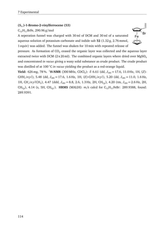
![7.2 Syntheses
7.2.2 Substrates and Catalyses
OAc(rac)-(E)-1,3-Diphenylallyl acetate[306]
C17H16O2, 252.33 g/mol
(rac)-(E)-3-hydroxy-1,3-diphenylpropene (2.45 g, 11.7 mmol,
1 equiv), acetic anhydride (1.3 ml, 1.4 g, 14 mmol, 1.2 equiv),
triethylamine (2.9 ml, 2.1 g, 21 mmol, 1.8 equiv) and 4-dimethylaminopyridine (7.1 mg,
0.058 mmol, 0.005 equiv) were dissolved in 25 ml of THF at 0 ◦
C using an ice bath. After
stirring for an hour the ice bath was removed and stirring was continued at rt over night
before evaporation of the solvent. The product was redissolved in diethyl ether and washed
with a saturated aqueous NH4Cl solution before drying over MgSO4 and concentration in
vacuo. Flash column chromatography (4:1 hexane/ethyl acetate) over silica gel yielded the
product as a colourless oil
Yield: 2.74 g, 92.9 %. 1
H-NMR (300 MHz, CDCl3): δ 7.6 – 7.33 (m, 10H, CHarom), 6.84 (d,
JHH = 15.9 Hz, 1H, CHallyl), 6.69 (d, JHH = 6.6 Hz, 1H, CHallyl), 6.55 (dd, JHH = 6.6 Hz, 15.9 Hz,
1H, CHallyl), 2.23 (s, 3H, CH3).
OAc(rac)-2-cyclohexenyl acetate[306]
C8H12O2, 140.18 g/mol
2-Cyclohexenol (0.98 ml, 0.98 g, 10 mmol, 1 equiv) was dissolved in THF (25 ml)
together with acetic anhydride (1.1 ml, 1.2 g, 12 mmol, 1.2 equiv), triethylamine
(2.5 ml, 1.8 g, 18 mmol, 1.8 equiv) and 4-dimethylaminopyridine (6.1 mg, 0.05 mmol,
0.005 equiv) at 0 ◦
C and the resulting reaction mixture stirred for 1 h before removing the
cooling bath. After stirring over night at rt the solvent was evaporated and the crude product
redissolved in diethyl ether, washed with saturated aqueous NH4Cl and dried over MgSO4.
Flash column chromatography (4:1 hexane/ethyl acetate) over silica gel yielded the pure
product as a colourless oil.
Yield: 584 mg, 42 %. 1
H-NMR (300 MHz, CDCl3): δ 5.90 (dt, JHH = 6.3, 3.9 Hz, 1H, CH),
5.66 (d, JHH = Hz, 1H, CH), 5.22 (s, 1H, CH), 2.01 (s, 3H, CH3), 1.5 – 2.1 (m, 6H, CH2).
CAS-number: 14447-34-8
Miyaura-Hayashi reaction[215]
Cyclohexenone (0.036 ml, 0.38 mmol, 1 equiv) was dissolved in ethyl acetate (3 ml) in a
10 ml Schlenk tube. The solution was thoroughly degassed before the addition of rhodium
catalyst 48, phenylboronic acid and 0.075 ml of a degassed aqueous solution of potassium
115](https://image.slidesharecdn.com/17dafaa7-bb25-4952-a328-ce8054639453-151111071008-lva1-app6892/85/eth21627-135-320.jpg)
![7 Experimental
hydroxide (2.5 M, 0.19 mmol, 0.5 equiv). After the predefined reaction time (cf. Table 19),
the reaction mixture was filtered through celite and the celite washed with several portions of
ethyl acetate. The filtrate was concentrated in vacuo and purified by flash column chromatog-
raphy over silica (n-hexane/ethyl acetate, 7:3) to yield the desired product. Enantiomeric
excess (%ee) was determined by HPLC (OD-H, n-hexane/iPrOH, 99:1, 0.5 ml/min, 254 nm,
tR1
= 33.7 min (R), tR2
= 37.2 min (S)).
O B
OHHO
cat.
EtOAc
O
Rha
, PhB(OH)2, T, t, yield ee
mol% equiv ◦
C h % %
4 4 40 24 99.5 rac
4 4 40 1 40 rac
4 1.5 40 24 95 rac
2 4 40 1 60 rac
4 4 0 24 0 n.a.
4 4 rt 24 14 16
4 4 rt 4 11 15
a
under the assumption that the rhodium complex
of ligand 5 has a molecular formula of the type
[C40H35ClFe2O2PRhS2]n
Table 19: Rhodium catalysed Miyaura-Hayashi reaction.[215]
Allylic substitution[307]
A 10 ml Schlenk tube was charged with bis((1,3-diphenylallyl)bromopalladium(II)), sulfox-
ophosphine ligand 5 and acetonitrile (1 ml). The solution was stirred at rt for 1 h resulting in
a colour change from orange to brown. 1 mg of salt was added and the solution was brought
to the reaction temperature (cf. Table 20) before the addition of 1,3-diphenylallyl acetate
(126 mg, 0.115 ml, 0.50 mmol, 1 equiv), dimethyl malonate (198 mg, 0.172 ml, 1.5 mmol,
3 equiv) and N,O-bis(trimethylsilyl) acetamide (305 mg, 0.368 ml, 1.5 mmol, 3 equiv) and
116](https://image.slidesharecdn.com/17dafaa7-bb25-4952-a328-ce8054639453-151111071008-lva1-app6892/85/eth21627-136-320.jpg)
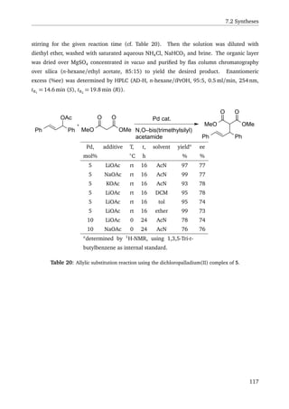

![References
[1] Kealy, T. J.; Pauson, P. L. Nature 1951, 168, 1039 – 1040.
[2] Miller, S. A.; Tebboth, J. A.; Tremaine, J. F. J. Chem. Soc. 1952, 632–635.
[3] Togni, A.; Hayashi, T. Ferrocenes: Homogeneous Catalysis, Organic Synthesis, Materials
Science. Wiley-VCH Verlag GmbH, Weinheim, Germany, 2007.
[4] Štˇepniˇcka, P. Ferrocenes: Ligands, Materials and Biomolecules. John Wiley & Sons, Ltd,
Chichester, UK, 2008.
[5] Day, L.-X.; Hou, X.-L. Chiral Ferrocenes in Asymmetric Catalysis. Wiley-VCH Verlag
GmbH & Co. KGaA, Weinheim, Germany, 2010.
[6] Woodward, R. B.; Rosenblum, M.; Whiting, M. C. Journal of the American Chemical
Society 1952, 74, 3458–3459.
[7] Wilkinson, G.; Rosenblum, M.; Whiting, M. C.; Woodward, R. B. Journal of the Ameri-
can Chemical Society 1952, 74, 2125–2126.
[8] Dunitz, J. D.; Orgel, L. E. Nature 1953, 171, 121–122.
[9] Dunitz, J. D.; Orgel, L. E.; Rich, A. Acta Crystallographica 1956, 9, 373–375.
[10] Blaser, H.-U.; Brieden, W.; Pugin, B.; Spindler, F.; Studer, M.; Togni, A. Topics in Catal-
ysis 2002, 19, 3–16.
[11] Zhou, Q.-L. Privileged Chiral Ligands and Catalysts. Wiley-VCH Verlag GmbH & Co.
KGaA, Weinheim, Germany, 2011.
[12] Lednicer, D.; Hauser, C. R. The Journal of Organic Chemistry 1959, 24, 43–46.
[13] Thomson, J. Tetrahedron Letters 1959, 1, 26 – 27.
[14] Schlögel, K. in Topics in Stereochemistry, (John Wiley & Sons, Inc., New York). pp
39 – 91. 1967.
119](https://image.slidesharecdn.com/17dafaa7-bb25-4952-a328-ce8054639453-151111071008-lva1-app6892/85/eth21627-139-320.jpg)
![References
[15] Cahn, R. S. Journal of Chemical Education 1964, 41, 116.
[16] Cahn, R. S.; Ingold, C.; Prelog, V. Angewandte Chemie International Edition in English
1966, 5, 385 – 415.
[17] Prelog, V.; Helmchen, G. Angewandte Chemie International Edition in English 1982, 21,
567 – 583.
[18] Deng, W.-P.; Snieckus, V.; Metallinos, C. in Chiral Ferrocenes in Asymmetric Catalysis,
(Wiley-VCH Verlag GmbH & Co. KGaA, Weinheim, Germany). pp 15 – 53. 2010.
[19] Whisler, M. C.; MacNeil, S.; Snieckus, V.; Beak, P. Angewandte Chemie International
Edition 2004, 43, 2206 – 2225.
[20] Aratani, T.; Gonda, T.; Nozaki, H. Tetrahedron 1970, 26, 5453 – 5464.
[21] Price, D.; Simpkins, N. S. Tetrahedron Letters 1995, 36, 6135 – 6136.
[22] Tsukazaki, M.; Tinkl, M.; Roglans, A.; Chapell, B. J.; Taylor, N. J.; Snieckus, V. Journal
of the American Chemical Society 1996, 118, 685–686.
[23] Laufer, R. S.; Veith, U.; Taylor, N. J.; Snieckus, V. Organic Letters 2000, 2, 629–631.
[24] Metallinos, C.; Szillat, H.; Taylor, N.; Snieckus, V. Advanced Synthesis Catalysis 2003,
345, 370 – 382.
[25] Dixon, A. J.; McGrath, M. J.; O’Brien, P. Organic Synthesis 2006, 83, 141–154.
[26] Horeau, A. Tetrahedron Letters 1961, 2, 506 – 512.
[27] Horeau, A. Tetrahedron Letters 1962, 3, 965 – 969.
[28] Falk, H.; Schlögl, K. Monatshefte für Chemie und verwandte Teile anderer Wissenschaften
1965, 96, 276–284.
[29] Falk, H.; Schlögl, K. Monatshefte für Chemie und verwandte Teile anderer Wissenschaften
1965, 96, 266–275.
[30] Schlögl, K.; Fried, M.; Falk, H. Monatshefte für Chemie und verwandte Teile anderer
Wissenschaften 1964, 95, 576–597.
[31] Latorre, A.; Urbano, A.; Carmen Carreno, M. Chem. Commun. 2011, 47, 8103–8105.
[32] Blaser, H.-U.; Federsel, H.-J. Asymmetric Catalysis on Industrial Scale. Wiley-VCH
Verlag GmbH & Co. KGaA, Weinheim, Germany, 2010.
120](https://image.slidesharecdn.com/17dafaa7-bb25-4952-a328-ce8054639453-151111071008-lva1-app6892/85/eth21627-140-320.jpg)
![References
[33] Lambusta, D.; Nicolosi, G.; Patti, A.; Piattelli, M. Tetrahedron Letters 1996, 37, 127 –
130.
[34] Bueno, A.; Rosol, M.; García, J.; Moyano, A. Advanced Synthesis Catalysis 2006, 348,
2590 – 2596.
[35] Ogasawara, M.; Watanabe, S.; Nakajima, K.; Takahashi, T. Pure and Applied Chemistry
2008, 80, 1109 – 1113.
[36] Ogasawara, M.; Watanabe, S.; Nakajima, K.; Takahashi, T. Organometallics 2008, 27,
6565–6569.
[37] Ogasawara, M.; Watanabe, S.; Nakajima, K.; Takahashi, T. Journal of the American
Chemical Society 2010, 132, 2136–2137.
[38] Ogasawara, M.; Watanabe, S.; Fan, L.; Nakajima, K.; Takahashi, T. Organometallics
2006, 25, 5201–5203.
[39] Hauser, C. R.; Lindsay, J. K. The Journal of Organic Chemistry 1957, 22, 906–908.
[40] Marquarding, D.; Klusacek, H.; Gokel, G.; Hoffmann, P.; Ugi, I. Journal of the American
Chemical Society 1970, 92, 5389–5393.
[41] Marquarding, D.; Klusacek, H.; Gokel, G.; Hoffmann, P.; Ugi, I. Angewandte Chemie
1970, 82, 360 – 361.
[42] Stüber, S.; Ugi, I. Synthesis 1973, 309–309.
[43] Boaz, N. W. Tetrahedron Letters 1989, 30, 2061 – 2064.
[44] Wright, J.; Frambes, L.; Reeves, P. Journal of Organometallic Chemistry 1994, 476,
215 – 217.
[45] Schwink, L.; Knochel, P. Tetrahedron Letters 1996, 37, 25 – 28.
[46] Blaser, H.; Spindler, F.; Studer, M. Applied Catalysis A: General 2001, 221, 119 – 143.
[47] Lam, W.-S.; Kok, S.; Au-Yeung, T.-L.; Wu, J.; Cheung, H.-Y.; Lam, F.-L.; Yeung, C.-H.;
Chan, A. Advanced Synthesis Catalysis 2006, 348, 370 – 374.
[48] Blaser, H.-U.; Pugin, B.; Spindler, F.; Thommen, M. Accounts of Chemical Research
2007, 40, 1240–1250.
[49] Gokel, G. W.; Ugi, I. K. Journal of Chemical Education 1972, 49, 294.
121](https://image.slidesharecdn.com/17dafaa7-bb25-4952-a328-ce8054639453-151111071008-lva1-app6892/85/eth21627-141-320.jpg)
![References
[50] Gokel, G.; Hoffmann, P.; Klusacek, H.; Marquarding, D.; Ruch, E.; Ugi, I. Angewandte
Chemie 1970, 82, 77 – 78.
[51] Richards, J. H.; Hill, E. A. Journal of the American Chemical Society 1959, 81, 3484–
3485.
[52] Trifan, D.; Bacskai, R. Tetrahedron Letters 1960, 1, 1 – 8.
[53] Hill, E. A.; Richards, J. H. Journal of the American Chemical Society 1961, 83, 3840–
3846.
[54] Hill, E. A.; Richards, J. H. Journal of the American Chemical Society 1961, 83, 4216–
4221.
[55] Kong, J.-R.; Ngai, M.-Y.; Krische, M. J. Journal of the American Chemical Society 2006,
128, 718–719.
[56] Boaz, N. W.; Jr., J. A. P.; Large, S. E. Tetrahedron Letters 2006, 47, 4033 – 4035.
[57] Boaz, N. W.; Jr., J. A. P.; Large, S. E. Tetrahedron: Asymmetry 2005, 16, 2063 – 2066.
[58] Sturm, T.; Weissensteiner, W.; Spindler, F. Advanced Synthesis Catalysis 2003, 345,
160 – 164.
[59] Schnyder, A.; Hintermann, L.; Togni, A. Angewandte Chemie International Edition in
English 1995, 34, 931 – 933.
[60] Barbaro, P.; Togni, A. Organometallics 1995, 14, 3570–3573.
[61] Hayashi, T.; Yamazaki, A. Journal of Organometallic Chemistry 1991, 413, 295 – 302.
[62] Togni, A.; Breutel, C.; Schnyder, A.; Spindler, F.; Landert, H.; Tijani, A. Journal of the
American Chemical Society 1994, 116, 4062–4066.
[63] Togni, A.; Breutel, C.; Soares, M. C.; Zanetti, N.; Gerfin, T.; Gramlich, V.; Spindler, F.;
Rihs, G. Inorganica Chimica Acta 1994, 222, 213 – 224.
[64] Okoroafor, M. O.; Ward, D. L.; Brubaker, C. H. Organometallics 1988, 7, 1504–1511.
[65] Honeychuck, R. V.; Okoroafor, M. O.; Shen, L. H.; Brubaker, C. H. Organometallics
1986, 5, 482–490.
[66] Hayashi, T.; Mise, T.; Fukushima, M.; Kagotani, M.; Nagashima, N.; Hamada, Y.; Mat-
sumoto, A.; Kawakami, S.; Konishi, M.; Yamamoto, K.; Kumada, M. Bulletin of the
Chemical Society of Japan 1980, 53, 1138–1151.
122](https://image.slidesharecdn.com/17dafaa7-bb25-4952-a328-ce8054639453-151111071008-lva1-app6892/85/eth21627-142-320.jpg)
![References
[67] Sawamura, M.; Hamashima, H.; Ito, Y. Tetrahedron: Asymmetry 1991, 2, 593 – 596.
[68] Sawamura, M.; Hamashima, H.; Sugawara, M.; Kuwano, R.; Ito, Y. Organometallics
1995, 14, 4549–4558.
[69] Rebière, F.; Riant, O.; Ricard, L.; Kagan, H. B. Angewandte Chemie International Edition
in English 1993, 32, 568 – 570.
[70] Zhao, S. H.; Samuel, O.; Kagan, H. B. Organic Syntheses 1990, 68, 49.
[71] Zhao, S.; Samuel, O.; Kagan, H. Tetrahedron 1987, 43, 5135 – 5144.
[72] Klunder, J. M.; Sharpless, K. B. The Journal of Organic Chemistry 1987, 52, 2598–
2602.
[73] Rebière, F.; Samuel, O.; Ricard, L.; Kagan, H. B. The Journal of Organic Chemistry
1991, 56, 5991–5999.
[74] Guillaneux, D.; Kagan, H. B. The Journal of Organic Chemistry 1995, 60, 2502–2505.
[75] Riant, O.; Argouarch, G.; Guillaneux, D.; Samuel, O.; Kagan, H. B. The Journal of
Organic Chemistry 1998, 63, 3511–3514.
[76] Cogan, D. A.; Liu, G.; Kim, K.; Backes, B. J.; Ellman, J. A. Journal of the American
Chemical Society 1998, 120, 8011–8019.
[77] Lagneau, N. M.; Chen, Y.; Robben, P. M.; Sin, H.-S.; Takasu, K.; Chen, J.-S.; Robinson,
P. D.; Hua, D. H. Tetrahedron 1998, 54, 7301 – 7334.
[78] Priego, J.; Mancheno, O. G.; Cabrera, S.; Carretero, J. C. Chem. Commun. 2001, 2026–
2027.
[79] Priego, J.; Mancheño, O. G.; Cabrera, S.; Carretero, J. C. The Journal of Organic
Chemistry 2002, 67, 1346–1353.
[80] Kloetzing, R. J.; Knochel, P. Tetrahedron: Asymmetry 2006, 17, 116 – 123.
[81] Ferber, B.; Kagan, H. Advanced Synthesis Catalysis 2007, 349, 493 – 507.
[82] Riant, O.; Samuel, O.; Kagan, H. B. Journal of the American Chemical Society 1993,
115, 5835–5836.
[83] Hanessian, S.; Ugolini, A.; Dubé, D.; Glamyan, A. Canadian Journal of Chemistry
1984, 62, 2146–2147.
123](https://image.slidesharecdn.com/17dafaa7-bb25-4952-a328-ce8054639453-151111071008-lva1-app6892/85/eth21627-143-320.jpg)
![References
[84] Riant, O.; Samuel, O.; Flessner, T.; Taudien, S.; Kagan, H. B. The Journal of Organic
Chemistry 1997, 62, 6733–6745.
[85] Abiko, A.; Masamune, S. Tetrahedron Letters 1992, 33, 5517 – 5518.
[86] McKennon, M. J.; Meyers, A. I.; Drauz, K.; Schwarm, M. The Journal of Organic
Chemistry 1993, 58, 3568–3571.
[87] Broggini, D. F. D. Phosphine and carbene ligands for asymmetric catalysis containing
two planar-chiral ferrocenyl units. Diss. ETH No. 15041, 2003.
[88] Bertogg, A.; Camponovo, F.; Togni, A. European Journal of Inorganic Chemistry 2005,
347 – 356.
[89] Bertogg, A.; Togni, A. Organometallics 2006, 25, 622–630.
[90] Larsen, A. O.; Taylor, R. A.; White, P. S.; Gagné, M. R. Organometallics 1999, 18,
5157–5162.
[91] Richards, C. J.; Damalidis, T.; Hibbs, D. E.; Hursthouse, M. B. Synlett 1995, 16, 74–76.
[92] Richards, C. J.; Mulvaney, A. W. Tetrahedron: Asymmetry 1996, 7, 1419 – 1430.
[93] Sammakia, T.; Latham, H. A.; Schaad, D. R. The Journal of Organic Chemistry 1995,
60, 10–11.
[94] Sammakia, T.; Latham, H. A. The Journal of Organic Chemistry 1995, 60, 6002–6003.
[95] Nishibayashi, Y.; Segawa, K.; Ohe, K.; Uemura, S. Organometallics 1995, 14, 5486–
5487.
[96] Helmchen, G.; Pfaltz, A. Accounts of Chemical Research 2000, 33, 336–345.
[97] Hargaden, G. C.; Guiry, P. J. Chemical Reviews 2009, 109, 2505–2550.
[98] Stuckwisch, C. G. The Journal of Organic Chemistry 1976, 41, 1173–1176.
[99] Dashan, L.; Trippett, S. Tetrahedron Letters 1983, 24, 2039 – 2040.
[100] Schaub, B.; Jenny, T.; Schlosser, M. Tetrahedron Letters 1984, 25, 4097 – 4100.
[101] Takemura, H.; Hirakawa, T.; Shinmyozu, T.; Inazu, T. Tetrahedron Letters 1984, 25,
5053 – 5056.
124](https://image.slidesharecdn.com/17dafaa7-bb25-4952-a328-ce8054639453-151111071008-lva1-app6892/85/eth21627-144-320.jpg)
![References
[102] Craig, D.; Roberts, N.; Tanswell, J. Australian Journal of Chemistry 1990, 43, 1487 –
1496.
[103] Gray, M.; Chapell, B. J.; Felding, J.; Taylor, N. J.; Snieckus, V. Synlett 1998, 19, 422–
424.
[104] Nettekoven, U. A. Phosphorus-Chiral ligands Based on Ferrocene: Stereoselective Syn-
thesis and Application in Asymmeteric Catalysis. Diss. University of Amsterdam, 2000.
[105] Nettekoven, U.; Widhalm, M.; Kamer, P. C. J.; van Leeuwen, P. W. N. M.; Mereiter, K.;
Lutz, M.; Spek, A. L. Organometallics 2000, 19, 2299–2309.
[106] Nettekoven, U.; Widhalm, M.; Kalchhauser, H.; Kamer, P. C. J.; van Leeuwen, P. W.
N. M.; Lutz, M.; Spek, A. L. The Journal of Organic Chemistry 2001, 66, 759–770.
[107] Vinci, D.; Mateus, N.; Wu, X.; Hancock, F.; Steiner, A.; Xiao, J. Organic Letters 2006,
8, 215–218.
[108] Vinci, D.; Martins, N.; Saidi, O.; Bacsa, J.; Brigas, A.; Xiao, J. Canadian Journal of
Chemistry 2009, 87, 171–175.
[109] Martins, N.; Mateus, N.; Vinci, D.; Saidi, O.; Brigas, A.; Bacsa, J.; Xiao, J. Org. Biomol.
Chem. 2012, 10, 4036–4042.
[110] Pfaltz, A.; Lotz, M.; Schönleber, M.; Pugin, B.; Kesselgruber, M.; Thommen, M. Method
For Producing Orthometalated and Orthosubstituted Aromatic Compounds. patent,
WO2005056566 2005.
[111] Fadini, L. Asymmetric olefin hydroamination catalyzed by Ni(II)-complexes. Diss. ETH
No. 15593, 2004.
[112] Barbaro, P.; Bianchini, C.; Togni, A. Organometallics 1997, 16, 3004–3014.
[113] Barbaro, P.; Bianchini, C.; Oberhauser, W.; Togni, A. Journal of Molecular Catalysis A:
Chemical 1999, 145, 139 – 146.
[114] Hintermann, L.; Perseghini, M.; Barbaro, P.; Togni, A. European Journal of Inorganic
Chemistry 2003, 601 – 609.
[115] Mejía, E.; Togni, A. Organometallics 2011, 30, 4765–4770.
[116] Fadini, L.; Togni, A. Helvetica Chimica Acta 2007, 90, 411 – 424.
125](https://image.slidesharecdn.com/17dafaa7-bb25-4952-a328-ce8054639453-151111071008-lva1-app6892/85/eth21627-145-320.jpg)
![References
[117] Sadow, A. D.; Haller, I.; Fadini, L.; Togni, A. Journal of the American Chemical Society
2004, 126, 14704–14705.
[118] Sadow, A. D.; Togni, A. Journal of the American Chemical Society 2005, 127, 17012–
17024.
[119] Walz, I. Katalytische enantioselektive Nazarov-Cyclisierung. Diss. ETH No. 17370,
2007.
[120] Walz, I.; Togni, A. Chem. Commun. 2008, 4315–4317.
[121] Öfele, K.; Herrmann, W. A.; Mihalios, D.; Elison, M.; Herdtweck, E.; Scherer, W.; Mink,
J. Journal of Organometallic Chemistry 1993, 459, 177 – 184.
[122] Jafarpour, L.; Nolan, S. P. volume 46 of Advances in Organometallic Chemistry, pp
181 – 222. Academic Press, 2000.
[123] Gischig, S.; Togni, A. European Journal of Inorganic Chemistry 2005, 4745 – 4754.
[124] Piper, T.; Lemal, D.; Wilkinson, G. Naturwissenschaften 1956, 43, 129–129.
[125] Armitage, D. A. F.; Corriu, R. J. P.; Kendrick, T. C.; Parbhoo, B.; Tilley, T. D.; White,
J. W.; Young, J. C. in The Silicon–Heteroatom Bond (1991), (John Wiley & Sons, Inc.,
Chichester, UK). pp 245 – 308. 2010.
[126] Speier, J. L.; Webster, J. A.; Barnes, G. H. Journal of the American Chemical Society
1957, 79, 974–979.
[127] Chalk, A. J.; Harrod, J. F. Journal of the American Chemical Society 1965, 87, 16–21.
[128] Kapoor, P.; Lövqvist, K.; Oskarsson, Å. Acta Crystallographica Section C 1995, 51, 611 –
613.
[129] Chatt, J.; Eaborn, C.; Ibekwe, S. D.; Kapoor, P. N. J. Chem. Soc. A 1970, 1343–1351.
[130] Zhu, J.; Lin, Z.; Marder, T. B. Inorganic Chemistry 2005, 44, 9384–9390.
[131] Kruck, T.; Job, E.; Klose, U. Angewandte Chemie International Edition in English 1968,
7, 374 – 374.
[132] MacInnis, M. C.; MacLean, D. F.; Lundgren, R. J.; McDonald, R.; Turculet, L.
Organometallics 2007, 26, 6522–6525.
[133] Auburn, M. J.; Stobart, S. R. Inorganic Chemistry 1985, 24, 318–323.
126](https://image.slidesharecdn.com/17dafaa7-bb25-4952-a328-ce8054639453-151111071008-lva1-app6892/85/eth21627-146-320.jpg)
![References
[134] Joslin, F. L.; Stobart, S. R. J. Chem. Soc., Chem. Commun. 1989, 504–505.
[135] Gossage, R. A.; McLennan, G. D.; Stobart, S. R. Inorganic Chemistry 1996, 35, 1729–
1732.
[136] Brost, R. D.; Bruce, G. C.; Joslin, F. L.; Stobart, S. R. Organometallics 1997, 16, 5669–
5680.
[137] Zhou, X. J.; Stobart, S. R. Organometallics 2001, 20, 1898–1900.
[138] Mitton, S. J.; McDonald, R.; Turculet, L. Organometallics 2009, 28, 5122–5136.
[139] Mitton, S.; McDonald, R.; Turculet, L. Angewandte Chemie International Edition 2009,
48, 8568 – 8571.
[140] MacInnis, M. C.; McDonald, R.; Ferguson, M. J.; Tobisch, S.; Turculet, L. Journal of the
American Chemical Society 2011, 133, 13622–13633.
[141] Balakrishna, M. S.; Chandrasekaran, P.; George, P. Coordination Chemistry Reviews
2003, 241, 87 – 117.
[142] Sangtrirutnugul, P.; Stradiotto, M.; Tilley, T. D. Organometallics 2006, 25, 1607–1617.
[143] Sangtrirutnugul, P.; Tilley, T. D. Organometallics 2007, 26, 5557–5568.
[144] Stradiotto, M.; Fujdala, K. L.; Tilley, T. D. Chem. Commun. 2001, 1200–1201.
[145] Davis, D. D.; Gray, C. E. Organometal. Chem. Rev. A 1960, 6, 283.
[146] Gilman, H.; Aoki, D. Journal of Organometallic Chemistry 1964, 1, 449 – 463.
[147] Gilman, H.; Lichtenwalter, G. D. Journal of the American Chemical Society 1958, 80,
608–611.
[148] Gilman, H.; Aoki, D. Journal of Organometallic Chemistry 1964, 2, 89 – 92.
[149] Corriu, R. J. P.; Guérin, C.; Kolani, B. Bulletin de la Société Chimique de France 1985,
973.
[150] Uhlig, W. Progress in Polymer Science 2002, 27, 255 – 305.
[151] Walter, C.; Fröhlich, R.; Oestreich, M. Tetrahedron 2009, 65, 5513 – 5520.
[152] Kleeberg, C.; Feldmann, E.; Hartmann, E.; Vyas, D. J.; Oestreich, M. Chemistry – A
European Journal 2011, 17, 13538 – 13543.
127](https://image.slidesharecdn.com/17dafaa7-bb25-4952-a328-ce8054639453-151111071008-lva1-app6892/85/eth21627-147-320.jpg)
![References
[153] Ojima, I.; Nihonyanagi, M.; Nagai, Y. J. Chem. Soc., Chem. Commun. 1972, 938a–
938a.
[154] Marciniec, B. Hydrosilylation: A Comprehensive Review on Recent Advances, volume 1.
Springer, Netherlands, 2009.
[155] Pioda, G.; Togni, A. Tetrahedron: Asymmetry 1998, 9, 3903 – 3910.
[156] Renner, H.; Schlamp, G.; Kleinwächter, I.; Drost, E.; Lüschow, H. M.; Tews, P.; Panster,
P.; Diehl, M.; Lang, J.; Kreuzer, T.; Knödler, A.; Starz, K. A.; Dermann, K.; Rothaut, J.;
Drieselman, R. (Wiley-VCH Verlag GmbH & Co. KGaA, ). pp 368–369. 2001.
[157] Camponovo, F. Chiral Ferrocenyl Amidines as Modular Ligands for Applications in
Asymmetric Catalysis. Diss. ETH No. 18199, 2009.
[158] Gmelin, Handbuch der Anorganischen Chemie Fe: Org. Verb., volume A5. Springer, 1981.
[159] Etievant, P.; Tainturier, G.; Gautheron, B. Comptes Rendus des Séances de l’Académie des
Sciences, Série C 1976, 283, 233–236.
[160] Gröbel, B.-T.; Seebach, D. Synthesis 1977, 357–402.
[161] Colvin, E. W. Silicon in Organic Synthesis. Butterworth and Co. Publications Ltd,
London, Boston, Sydney, Wellington, Durban, Toronto, 1981.
[162] Reuter, M. J.; Damrauer, R. Journal of Organometallic Chemistry 1974, 82, 201 – 208.
[163] Kondo, T.; Yamamoto, K.; Kumada, M. Journal of Organometallic Chemistry 1972, 35,
C30 – C32.
[164] Kondo, T.; Yamamoto, K.; Omura, T.; Kumada, M. Journal of Organometallic Chemistry
1973, 60, 287 – 301.
[165] Ireland, T.; Almena Perea, J. J.; Knochel, P. Angewandte Chemie International Edition
1999, 38, 1457 – 1460.
[166] Moran, M.; Casado, C. M.; Cuadrado, I.; Losada, J. Organometallics 1993, 12, 4327–
4333.
[167] Losada, J.; Cuadrado, I.; Morán, M.; Casado, C. M.; Alonso, B.; Barranco, M. Analytica
Chimica Acta 1997, 338, 191 – 198.
128](https://image.slidesharecdn.com/17dafaa7-bb25-4952-a328-ce8054639453-151111071008-lva1-app6892/85/eth21627-148-320.jpg)
![References
[168] Cuadrado, I.; Morán, M.; Losada, J.; Casado, C. M.; Pascual, C.; Alonso, B.; Lobete, F.
(JAI Press Inc., Greebwich, Conneticut and London, England). volume 3 of Advances
in Organometallic Chemistry. chapter Organometallic Dendritic Macromolecules, pp
151 – 195. 1996.
[169] Ryan, J.; Speier, J. The Journal of Organic Chemistry 1959, 24, 2052–2053.
[170] Petrow Zhurnal Obshchei Khimii: Journal of General Chemistry of the U.S.S.R. : English
Translation 1960, 30, 376.
[171] Etievant, P.; Gautheron, B.; Tainturier, G. Bulletin de la Société Chimique de France
1978, 292–298.
[172] Hartinger, C. G.; Nazarov, A. A.; Chevchenko, V.; Arion, V. B.; Galanski, M.; Keppler,
B. K. Dalton Trans. 2003, 3098–3102.
[173] Connell, A.; Holliman, P. J.; Butler, I. R.; Male, L.; Coles, S. J.; Horton, P. N.; Hursthouse,
M. B.; Clegg, W.; Russo, L. Journal of Organometallic Chemistry 2009, 694, 2020 –
2028.
[174] Bondi, A. The Journal of Physical Chemistry 1964, 68, 441–451.
[175] Mantina, M.; Chamberlin, A. C.; Valero, R.; Cramer, C. J.; Truhlar, D. G. The Journal
of Physical Chemistry A 2009, 113, 5806–5812.
[176] Wuts, P. G. M.; Greene, T. W. (John Wiley & Sons, Inc., ). pp 431 – 532. 2006.
[177] Soderquist, J. A.; Miranda, E. I. Journal of the American Chemical Society 1992, 114,
10078–10079.
[178] Takaya, J.; Iwasawa, N. Dalton Trans. 2011, 40, 8814–8821.
[179] Appleton, T.; Clark, H.; Manzer, L. Coordination Chemistry Reviews 1973, 10, 335 –
422.
[180] Chan, D.; Duckett, S. B.; Heath, S. L.; Khazal, I. G.; Perutz, R. N.; Sabo-Etienne, S.;
Timmins, P. L. Organometallics 2004, 23, 5744–5756.
[181] Moulton, C. J.; Shaw, B. L. J. Chem. Soc., Dalton Trans. 1976, 1020–1024.
[182] Errington, J.; McDonald, W. S.; Shaw, B. L. J. Chem. Soc., Dalton Trans. 1980, 2312–
2314.
129](https://image.slidesharecdn.com/17dafaa7-bb25-4952-a328-ce8054639453-151111071008-lva1-app6892/85/eth21627-149-320.jpg)
![References
[183] van Koten, G.; Timmer, K.; Noltes, J. G.; Spek, A. L. J. Chem. Soc., Chem. Commun.
1978, 250–252.
[184] van Koten, G.; Jastrzebski, J. T.; Noltes, J. G.; Spek, A. L.; Schoone, J. C. Journal of
Organometallic Chemistry 1978, 148, 233 – 245.
[185] Koten, G. Organometallic Pincer Chemistry, volume 40 of Topics in Organometallic
Chemistry. Springer Berlin Heidelberg, 2013.
[186] Morales-Morales, D. Rev. Soc. Quím. Méx. 2004, 48, 338–346.
[187] Albrecht, M.; van Koten, G. Angewandte Chemie International Edition 2001, 40, 3750 –
3781.
[188] van der Boom, M. E.; Milstein, D. Chemical Reviews 2003, 103, 1759–1792.
[189] Dupont, J.; Consorti, C. S.; Spencer, J. The Chemistry of Pincer Compounds. Elsevier
Science B.V., Amsterdam, 2007.
[190] Leis, W.; Mayer, H. A.; Kaska, W. C. Coordination Chemistry Reviews 2008, 252, 1787 –
1797.
[191] Shaw, B. L. Journal of the American Chemical Society 1975, 97, 3856–3857.
[192] Shaw, B. L. Journal of Organometallic Chemistry 1980, 200, 307 – 318.
[193] Haenel, M. W.; Oevers, S.; Angermund, K.; Kaska, W. C.; Fan, H.-J.; Hall, M. B. Ange-
wandte Chemie International Edition 2001, 40, 3596 – 3600.
[194] M. Jensen, C. Chem. Commun. 1999, 2443–2449.
[195] Singleton, J. T. Tetrahedron 2003, 59, 1837 – 1857.
[196] Zhao, J.; Goldman, A. S.; Hartwig, J. F. Science 2005, 307, 1080–1082.
[197] Goldman, A. S.; Roy, A. H.; Huang, Z.; Ahuja, R.; Schinski, W.; Brookhart, M. Science
2006, 312, 257–261.
[198] Pugh, D.; Danopoulos, A. A. Coordination Chemistry Reviews 2007, 251, 610 – 641.
[199] Corey, J. Y.; Braddock-Wilking, J. Chemical Reviews 1999, 99, 175–292.
[200] Auburn, M. J.; Holmes-Smith, R. D.; Stobart, S. R.; Bakshi, P. K.; Cameron, T. S.
Organometallics 1996, 15, 3032–3036.
130](https://image.slidesharecdn.com/17dafaa7-bb25-4952-a328-ce8054639453-151111071008-lva1-app6892/85/eth21627-150-320.jpg)
![References
[201] Ruddy, A. J.; Mitton, S. J.; McDonald, R.; Turculet, L. Chem. Commun. 2012, 48,
1159–1161.
[202] MacLean, D. F.; McDonald, R.; Ferguson, M. J.; Caddell, A. J.; Turculet, L. Chem.
Commun. 2008, 5146–5148.
[203] Butler, I. R. Inorganic Chemistry Communications 2008, 11, 15 – 19.
[204] Rebière, F.; Samuel, O.; Kagan, H. Tetrahedron Letters 1990, 31, 3121 – 3124.
[205] Baechler, R. D.; Mislow, K. Journal of the American Chemical Society 1970, 92, 3090–
3093.
[206] Rauk, A.; Allen, L. C.; Mislow, K. Angewandte Chemie International Edition in English
1970, 9, 400 – 414.
[207] Heinemann, F.; Weber, I.; Zenneck, U. Journal of Chemical Crystallography 2007, 37,
165–170.
[208] Sinnokrot, M. O.; Valeev, E. F.; Sherrill, C. D. Journal of the American Chemical Society
2002, 124, 10887–10893.
[209] Blount, J.; Camp, D.; Hart, R.; Healy, P.; Skelton, B.; White, A. Australian Journal of
Chemistry 1994, 47, 1631 – 1639.
[210] Houlton, A.; Roberts, R. M. G.; Silver, J.; Drew, M. G. B. J. Chem. Soc., Dalton Trans.
1990, 1543–1547.
[211] Romeo, R.; Tobe, M. L. Inorganic Chemistry 1974, 13, 1991–1996.
[212] Kukushkin, Y. N.; Vyaz’menskii, Y. E.; Zorina, L. I. Russian Journal of Inorganic
Chemistry 1968, 13, 1573 – 1576.
[213] Kukushkin, Y. N.; Trusova, K. M. Russian Journal of Inorganic Chemistry 1971, 16,
139–140.
[214] Mercer, A.; Trotter, J. J. Chem. Soc., Dalton Trans. 1975, 2480–2483.
[215] Dornan, P. K.; Leung, P. L.; Dong, V. M. Tetrahedron 2011, 67, 4378 – 4384.
[216] Rayner, D. R.; Gordon, A. J.; Mislow, K. Journal of the American Chemical Society 1968,
90, 4854–4860.
131](https://image.slidesharecdn.com/17dafaa7-bb25-4952-a328-ce8054639453-151111071008-lva1-app6892/85/eth21627-151-320.jpg)
![References
[217] Kingsbury, C. A.; Cram, D. J. Journal of the American Chemical Society 1960, 82, 1810–
1819.
[218] Fernández, I.; Khiar, N. Chemical Reviews 2003, 103, 3651–3706.
[219] Kagan, H. in Organosulfur Chemistry in Asymmetric Synthesis, (Wiley-VCH Verlag
GmbH & Co. KGaA, Weinheim, Germany). pp 1 – 29. 2009.
[220] Solladié, G. Synthesis 1981, 185–196.
[221] Valentine Jr, D.; Scott, J. W. Synthesis 1978, 329–356.
[222] ˇCaplar, V.; Comisso, G.; Šunji´c, V. Synthesis 1981, 85–116.
[223] Pellissier, H. Tetrahedron 2006, 62, 5559 – 5601.
[224] James, B. R.; McMillan, R. S.; Reimer, K. J. Journal of Molecular Catalysis 1976, 1,
439 – 441.
[225] Kagan, H. B.; Dang-Tuan-Phat Journal of the American Chemical Society 1972, 94,
6429–6433.
[226] James, B. R.; McMillan, R. S. Canadian Journal of Chemistry 1977, 55, 3927–3932.
[227] Kvintovics, P.; James, B. R.; Heil, B. J. Chem. Soc., Chem. Commun. 1986, 1810–1811.
[228] Alcock, N. W.; Brown, J. M.; Evans, P. L. Journal of Organometallic Chemistry 1988,
356, 233 – 247.
[229] Petra, D. G. I.; Kamer, P. C. J.; Spek, A. L.; Schoemaker, H. E.; van Leeuwen, P. W. N. M.
The Journal of Organic Chemistry 2000, 65, 3010–3017.
[230] Khiar, N.; Fernández, I.; Alcudia, F. Tetrahedron Letters 1993, 34, 123 – 126.
[231] Ichikawa, E.; Suzuki, M.; Yabu, K.; Albert, M.; Kanai, M.; Shibasaki, M. Journal of the
American Chemical Society 2004, 126, 11808–11809.
[232] Fernández, I.; Valdivia, V.; Leal, M. P.; Khiar, N. Organic Letters 2007, 9, 2215–2218.
[233] Mariz, R.; Luan, X.; Gatti, M.; Linden, A.; Dorta, R. Journal of the American Chemical
Society 2008, 130, 2172–2173.
[234] Mariz, R.; Burgi, J.; Gatti, M.; Drinkel, E.; Luan, X.; Dorta, R. CHIMIA International
Journal for Chemistry 2009, 63, 508–511.
132](https://image.slidesharecdn.com/17dafaa7-bb25-4952-a328-ce8054639453-151111071008-lva1-app6892/85/eth21627-152-320.jpg)
![References
[235] Mariz, R.; Poater, A.; Gatti, M.; Drinkel, E.; Bürgi, J. J.; Luan, X.; Blumentritt, S.;
Linden, A.; Cavallo, L.; Dorta, R. Chemistry – A European Journal 2010, 16, 14335 –
14347.
[236] Bürgi, J.; Mariz, R.; Gatti, M.; Drinkel, E.; Luan, X.; Blumentritt, S.; Linden, A.; Dorta,
R. Angewandte Chemie International Edition 2009, 48, 2768 – 2771.
[237] Chen, Q.-A.; Dong, X.; Chen, M.-W.; Wang, D.-S.; Zhou, Y.-G.; Li, Y.-X. Organic Letters
2010, 12, 1928–1931.
[238] Chen, J.; Chen, J.; Lang, F.; Zhang, X.; Cun, L.; Zhu, J.; Deng, J.; Liao, J. Journal of
the American Chemical Society 2010, 132, 4552–4553.
[239] Zhang, X.; Chen, J.; Han, F.; Cun, L.; Liao, J. European Journal of Organic Chemistry
2011, 1443 – 1446.
[240] Khiar, N.; Salvador, Á.; Valdivia, V.; Chelouan, A.; Alcudia, A.; Álvarez, E.; Fernández,
I. The Journal of Organic Chemistry 2013, 78, 6510–6521.
[241] Drinkel, E. E.; Wu, L.; Linden, A.; Dorta, R. Organometallics 2014, 33, 627–636.
[242] Miyashita, A.; Yasuda, A.; Takaya, H.; Toriumi, K.; Ito, T.; Souchi, T.; Noyori, R. Jour-
nal of the American Chemical Society 1980, 102, 7932 – 7934.
[243] Chen, M. S.; White, M. C. Journal of the American Chemical Society 2004, 126, 1346–
1347.
[244] Chen, M. S.; Prabagaran, N.; Labenz, N. A.; White, M. C. Journal of the American
Chemical Society 2005, 127, 6970–6971.
[245] Fraunhoffer, K. J.; Prabagaran, N.; Sirois, L. E.; White, M. C. Journal of the American
Chemical Society 2006, 128, 9032–9033.
[246] Stang, E. M.; Christina White, M. Nat Chem 2009, 1, 547 – 551.
[247] Nesmejanowa, O. A.; Perewalowa, E. G. Doklady Akademii Nauk SSSR 1959, 126,
1004 – 1006.
[248] Perewalowa, E. G.; Nesmejanowa, O. A. Doklady Akademii Nauk SSSR 1960, 132,
1093 – 1094.
[249] Sawamura, M.; Yamauchi, A.; Takegawa, T.; Ito, Y. J. Chem. Soc., Chem. Commun.
1991, 874–875.
133](https://image.slidesharecdn.com/17dafaa7-bb25-4952-a328-ce8054639453-151111071008-lva1-app6892/85/eth21627-153-320.jpg)
![References
[250] Espino, G.; Xiao, L.; Puchberger, M.; Mereiter, K.; Spindler, F.; Manzano, B. R.; Jalon,
F. A.; Weissensteiner, W. Dalton Trans. 2009, 2751–2763.
[251] Xiao, L.; Mereiter, K.; Spindler, F.; Weissensteiner, W. Tetrahedron: Asymmetry 2001,
12, 1105 – 1108.
[252] Kuwano, R. in Chiral Ferrocenes in Asymmetric Catalysis, (Wiley-VCH Verlag GmbH &
Co. KGaA, Weinheim, Germany). pp 283 – 305. 2010.
[253] Zirakzadeh, A.; Groß, M. A.; Wang, Y.; Mereiter, K.; Spindler, F.; Weissensteiner, W.
Organometallics 2013, 32, 1075–1084.
[254] Dong, T.-Y.; Chang, C.-K.; Lee, S.-H.; Lai, L.-L.; Chiang, M. Y.-N.; Lin, K.-J.
Organometallics 1997, 16, 5816–5825.
[255] Dong, T.-Y.; Huang, B.-R.; Lin, M.-C.; Chiang, M. Y. Polyhedron 2003, 22, 1199 – 1204.
[256] Lee, C.; Yang, W.; Parr, R. G. Phys. Rev. B 1988, 37, 785–789.
[257] Becke, A. D. Phys. Rev. A 1988, 38, 3098–3100.
[258] Becke, A. D. The Journal of Chemical Physics 1993, 98, 5648–5652.
[259] Perdew, J. P. Phys. Rev. B 1986, 33, 8822–8824.
[260] Gaussian 09, Rev D.01Frisch, M. J.; Trucks, G. W.; Schlegel, H. B.; Scuseria, G. E.;
Robb, M. A.; Cheeseman, J. R.; Scalmani, G.; Barone, V.; Mennucci, B.; Petersson, G.
A.; Nakatsuji, H.; Caricato, M.; Li, X.; Hratchian, H. P.; Izmaylov, A. F.; Bloino, J.;
Zheng, G.; Sonnenberg, J. L.; Hada, M.; Ehara, M.; Toyota, K.; Fukuda, R.; Hasegawa,
J.; Ishida, M.; Nakajima, T.; Honda, Y.; Kitao, O.; Nakai, H.; Vreven, T.; Montgomery, J.
A., Jr.; Peralta, J. E.; Ogliaro, F.; Bearpark, M.; Heyd, J. J.; Brothers, E.; Kudin, K. N.;
Staroverov, V. N.; Kobayashi, R.; Normand, J.; Raghavachari, K.; Rendell, A.; Burant,
J. C.; Iyengar, S. S.; Tomasi, J.; Cossi, M.; Rega, N.; Millam, N. J.; Klene, M.; Knox,
J. E.; Cross, J. B.; Bakken, V.; Adamo, C.; Jaramillo, J.; Gomperts, R.; Stratmann, R.
E.; Yazyev, O.; Austin, A. J.; Cammi, R.; Pomelli, C.; Ochterski, J. W.; Martin, R. L.;
Morokuma, K.; Zakrzewski, V. G.; Voth, G. A.; Salvador, P.; Dannenberg, J. J.; Dapprich,
S.; Daniels, A. D.; Farkas, Ö.; Foresman, J. B.; Ortiz, J. V.; Cioslowski, J.; Fox, D. J.
Gaussian, Inc., Wallingford CT, 2009.
[261] Gauss, J. The Journal of Chemical Physics 1993, 99, 3629–3643.
[262] London, F. Journal de Physique et le Radium 1937, 8, 397.
134](https://image.slidesharecdn.com/17dafaa7-bb25-4952-a328-ce8054639453-151111071008-lva1-app6892/85/eth21627-154-320.jpg)
![References
[263] Ditchfield, R. Molecular Physics 1974, 27, 789–807.
[264] Wolinski, K.; Hinton, J. F.; Pulay, P. Journal of the American Chemical Society 1990,
112, 8251–8260.
[265] Biscarini, P.; Fusina, L.; Nivellini, G. D. J. Chem. Soc., Dalton Trans. 1972, 1921–1923.
[266] Allen, F. H.; Kennard, O.; Watson, D. G.; Brammer, L.; Orpen, A. G.; Taylor, R. J. Chem.
Soc., Perkin Trans. 2 1987, S1–S19.
[267] Childs, R. F.; Mulholland, D. L.; Nixon, A. Canadian Journal of Chemistry 1982, 60,
801–808.
[268] Childs, R. F.; Mulholland, D. L.; Nixon, A. Canadian Journal of Chemistry 1982, 60,
809–812.
[269] Brunn, J.; Beck, C. Zeitschrift für Chemie 1977, 17, 296 – 297.
[270] Laszlo, P.; Teston, M. Journal of the American Chemical Society 1990, 112, 8750–8754.
[271] Mallouk, T. E.; Rosenthal, G. L.; Mueller, G.; Brusasco, R.; Bartlett, N. Inorganic
Chemistry 1984, 23, 3167–3173.
[272] Brownridge, S.; Krossing, I.; Passmore, J.; Jenkins, H.; Roobottom, H. Coordination
Chemistry Reviews 2000, 197, 397 – 481.
[273] Christe, K. O.; Dixon, D. A.; McLemore, D.; Wilson, W. W.; Sheehy, J. A.; Boatz, J. A.
Journal of Fluorine Chemistry 2000, 101, 151 – 153.
[274] Hwang, I.-C.; Seppelt, K. Angewandte Chemie 2001, 113, 3803 – 3805.
[275] Cameron, T. S.; Deeth, R. J.; Dionne, I.; Du, H.; Jenkins, H. D. B.; Krossing, I.; Pass-
more, J.; Roobottom, H. K. Inorganic Chemistry 2000, 39, 5614–5631.
[276] Krossing, I.; Bihlmeier, A.; Raabe, I.; Trapp, N. Angewandte Chemie International Edi-
tion 2003, 42, 1531 – 1534.
[277] Butti, P. Catalytic, enantioselective carbon-phosphorus bond forming reactions. Diss.
ETH No. 18839, 2009.
[278] Mita, T.; Chen, J.; Sugawara, M.; Sato, Y. Angewandte Chemie International Edition
2011, 50, 1393–1396.
[279] Mita, T.; Higuchi, Y.; Sato, Y. Organic Letters 2011, 13, 2354–2357.
135](https://image.slidesharecdn.com/17dafaa7-bb25-4952-a328-ce8054639453-151111071008-lva1-app6892/85/eth21627-155-320.jpg)
![References
[280] Mita, T.; Higuchi, Y.; Sato, Y. Synthesis 2012, 43, 194–200.
[281] Mita, T.; Sugawara, M.; Hasegawa, H.; Sato, Y. The Journal of Organic Chemistry 2012,
77, 2159–2168.
[282] Liebeskind, L. S.; na Cabrera, P. Organic Syntheses 2000, 77, 135.
[283] Eisenberger, P.; Gischig, S.; Togni, A. Chemistry – A European Journal 2006, 12, 2579–
2586.
[284] Kieltsch, I.; Eisenberger, P.; Togni, A. Angewandte Chemie 2007, 119, 768–771.
[285] Capone, S.; Kieltsch, I.; Flögel, O.; Lelais, G.; Togni, A.; Seebach, D. Helvetica Chimica
Acta 2008, 91, 2035–2056.
[286] Stanek, K.; Koller, R.; Kieltsch, I.; Eisenberger, P.; Togni, A. 2009. Trifluoromethyl-1,3-
dihydro-3,3-dimethyl-1,2-benziodoxole. e-EROS Encyclopedia of Reagents for Organic
Synthesis.
[287] Stanek, K.; Koller, R.; Kieltsch, I.; Eisenberger, P.; Togni, A. 2009. 1-(Trifluoromethyl)-
1,2-benziodoxol-3(1H)-one. e-EROS Encyclopedia of Reagents for Organic Synthesis.
[288] Eisenberger, P.; Kieltsch, I.; Koller, R.; Stanek, K.; Togni, A. Organic Synthesis 2011,
88, 168 – 180.
[289] Santschi, N.; Togni, A. The Journal of Organic Chemistry 2011, 76, 4189–4193.
[290] Rhode, C.; Lemke, J.; Lieb, M.; Metzler-Nolte, N. Synthesis 2009, 2015–2018.
[291] Teverovskiy, G.; Surry, D. S.; Buchwald, S. L. Angewandte Chemie International Edition
2011, 50, 7312–7314.
[292] Shriver, D. F.; Drezdzon, M. A. The Manipulation of Air-Sensitive Compounds. Wiley,
Chichester, 2nd edition, 1986.
[293] Solladié, G.; Hutt, J.; Girardin, A. Synthesis 1987, 173–173.
[294] Solladié, G.; Somny, F.; Colobert, F. Tetrahedron: Asymmetry 1997, 8, 801 – 810.
[295] Aso, Y.; Yamashita, H.; Otsubo, T.; Ogura, F. The Journal of Organic Chemistry 1989,
54, 5627–5629.
[296] Harris, R. K.; Becker, E. D.; Cabral de Menezes, S. M.; Goodfellow, R.; Granger, P. Pure
and Applied Chemistry 2001, 73, 1795–1818.
136](https://image.slidesharecdn.com/17dafaa7-bb25-4952-a328-ce8054639453-151111071008-lva1-app6892/85/eth21627-156-320.jpg)
![References
[297] SAINT+, Software for CCD Diffractometers, v. 6.01 and SAINT, v. 6.02. Bruker AXS,
Inc., Madison, WI, 2001.
[298] Sheldrick, G. M. Acta Crystallographica 1990, A46, 467–473.
[299] Sheldrick, G. M.; SHELXL-97 Program for Crystal Structure Refinement. Universität
Göttingen, Göttingen, Germany, 1999.
[300] Blessing, R. H. Acta Crystallographica 1995, A51, 33–38.
[301] Flack, H. D. Acta Crystallographica 1983, A39, 876–881.
[302] Bernadinelli, G.; Flack, H. D. Acta Crystallographica 1985, A41, 500–511.
[303] Acta Crystallographica 2010, C66, e1–e8.
[304] Herberhold, M.; Nuyken, O.; Pöhlmann, T. Journal of Organometallic Chemistry 1991,
405, 217 – 227.
[305] Kauffman, G. B.; Teter, L. A.; C., I. T.; Clifford, A. in Inorganic Syntheses, (John Wiley
& Sons, Inc., Hoboken, NJ, USA). pp 9 – 12. 2007.
[306] Onaran, M. B.; Seto, C. T. The Journal of Organic Chemistry 2003, 68, 8136–8141.
[307] Chen, J.; Lang, F.; Li, D.; Cun, L.; Zhu, J.; Deng, J.; Liao, J. Tetrahedron: Asymmetry
2009, 20, 1953 – 1956.
137](https://image.slidesharecdn.com/17dafaa7-bb25-4952-a328-ce8054639453-151111071008-lva1-app6892/85/eth21627-157-320.jpg)

![Appendix
IR infrared
J coupling constant
MALDI matrix-assisted laser desorption / ionisation
Me methyl
MeOH methanol
min minute
MS mass spectrometry
NMR nuclear magnetic resonance
NOESY nuclear Overhauser effect spectroscopy
Np naphthyl
ORTEP Oak Ridge thermal ellipsoid plot
OTf trifluoromethanesulfonate (triflate)
Ph phenyl
PPFA (SFc)-1-diphenylphosphino-2-[(R)-(1-N,N-dimethylamino)ethyl]ferrocene
ppm parts per million
rac racemic
rt room temperature
TBAF tetrabutylammonium fluoride
t-Bu tert-butyl
THF tetrahydrofuran
TLC thin layer chromatography
TMEDA tetramethylethylendiamine
Ts tosyl
xiv](https://image.slidesharecdn.com/17dafaa7-bb25-4952-a328-ce8054639453-151111071008-lva1-app6892/85/eth21627-160-320.jpg)
![Appendix
8.2 Crystallographic Data
(SFc)-2-[α-(Diphenylphosphino)ferrocenyl]-1,3-dithiane (25)
identification code pl047 CCDC number
cryst. method. DCM/n-hexane empirical formula C26H25FePS2
shape plate moiety formula C26H25FePS2
color orange Mr 488.40
cryst size (mm) 0.19 × 0.14 × 0.05 T (K) 100(2)
exp. time/frame (s) 10 solution method direct
crystal system monoclinic space group P21
a (Å) 8.9024(11) α (◦
) 90
b (Å) 11.0031(13) β (◦
) 109.225(2)
c (Å) 12.1109(14) γ (◦
) 90
V (Å3
) 1120.2(2) Z 2
ρcalc (g cm−3
) 1.448 µ (mm−1
) 0.942
θmin, θmax (◦
) 2.42, 28.38 F000 508
limiting indices −11 ≤ h ≤ 11 data 5519
−14 ≤ k ≤ 14 restraints 1
−16 ≤ l ≤ 15 parameters 271
collected/unique reflexions 11713 / 5519 Rint 0.0373
Tmax, Tmin 0.9570, 0.8435 ∆ρmax, ∆ρmin (e Å−3
) 0.632, –0.270
final R [I > 2σ(I)] 0.0400 S 1.010
final R [all data] 0.0447 Flack parameter 0.015(14)
xv](https://image.slidesharecdn.com/17dafaa7-bb25-4952-a328-ce8054639453-151111071008-lva1-app6892/85/eth21627-161-320.jpg)
![Appendix
(SFc,SFc,SS,SS)-Bis-[2-(p-tolylsulfinyl)ferrocenyl]phenylphosphine (5)
url identification code lm_pl_010 CCDC number
cryst. method. DCM/n-hexane empirical formula C40H35.96Fe2O2.48PS2
shape prism moiety formula C40H35Fe2O2PS2, H0.96O0.48
color orange Mr 762.07
cryst size (mm) 0.48 × 0.37 × 0.27 T (K) 100(2)
exp. time/frame (s) 1 solution method direct
crystal system orthorhombic space group P212121
a (Å) 11.6275(6) α (◦
) 90
b (Å) 15.9011(8) β (◦
) 90
c (Å) 17.8262(8) γ (◦
) 90
V (Å3
) 3295.9(3) Z 4
ρcalc (g cm−3
) 1.536 µ (mm−1
) 1.094
θmin, θmax (◦
) 1.72, 28.33 F000 1575
limiting indices −15 ≤ h ≤ 15 data 8206
−21 ≤ k ≤ 21 restraints 0
−23 ≤ l ≤ 23 parameters 436
collected/unique reflexions 34410 / 8206 Rint 0.0492
Tmax, Tmin 0.7566, 0.6239 ∆ρmax, ∆ρmin (e Å−3
) 0.552, –0.276
final R [I > 2σ(I)] 0.0335 S 1.010
final R [all data] 0.0368 Flack parameter 0.005(11)
xvi](https://image.slidesharecdn.com/17dafaa7-bb25-4952-a328-ce8054639453-151111071008-lva1-app6892/85/eth21627-162-320.jpg)
![Appendix
(RFc,RFc,RS,RS)-Bis-[2-(t-butylsulfinyl)ferrocene] (6)
identification code mm-03_d CCDC number
cryst. method. DCM empirical formula C28H34Fe2O2S2
shape needle moiety formula C28H34Fe2O2S2
color yellow Mr 578.37
cryst size (mm) 0.40 × 0.11 × 0.08 T (K) 100(2)
exp. time/frame (s) 10 solution method direct
crystal system orthorhombic space group P212121
a (Å) 9.8640(6) α (◦
) 90
b (Å) 12.9300(8) β (◦
) 90
c (Å) 20.0423(13) γ (◦
) 90
V (Å3
) 2556.2(3) Z 4
ρcalc (g cm−3
) 1.503 µ (mm−1
) 1.323
θmin, θmax (◦
) 1.87, 31.15 F000 1208
limiting indices −13 ≤ h ≤ 13 data 7736
−18 ≤ k ≤ 18 restraints 0
−28 ≤ l ≤ 28 parameters 313
collected/unique reflexions 29809 / 7736 Rint 0.0921
Tmax, Tmin ∆ρmax, ∆ρmin (e Å−3
) 0.431, –0.545
final R [I > 2σ(I)] 0.0373 S 0.955
final R [all data] 0.0444 Flack parameter 0.016(11)
xvii](https://image.slidesharecdn.com/17dafaa7-bb25-4952-a328-ce8054639453-151111071008-lva1-app6892/85/eth21627-163-320.jpg)
![Appendix
(Ra,RFc,RFc)-Bis-[2-(t-butylsulfanyl)ferrocene] (7)
identification code mm13 CCDC number
cryst. method. DCM empirical formula C28H34Fe2S2
shape prism moiety formula C28H34Fe2S2
color orange Mr 546.37
cryst size (mm) 0.17 × 0.13 × 0.12 T (K) 100(2)
exp. time/frame (s) 20 solution method direct
crystal system orthorhombic space group P212121
a (Å) 9.9678(5) α (◦
) 90
b (Å) 12.6621(6) β (◦
) 90
c (Å) 20.1445(10) γ (◦
) 90
V (Å3
) 2542.5(2) Z 4
ρcalc (g cm−3
) 1.427 µ (mm−1
) 1.320
θmin, θmax (◦
) 1.90, 31.16 F000 1144
limiting indices −14 ≤ h ≤ 13 data 7803
−18 ≤ k ≤ 18 restraints 0
−27 ≤ l ≤ 28 parameters 295
collected/unique reflexions 39664 / 7803 Rint 0.0756
Tmax, Tmin ∆ρmax, ∆ρmin (e Å−3
) 0.387, –0.425
final R [I > 2σ(I)] 0.0329 S 0.945
final R [all data] 0.0389 Flack parameter 0.014(9)
xviii](https://image.slidesharecdn.com/17dafaa7-bb25-4952-a328-ce8054639453-151111071008-lva1-app6892/85/eth21627-164-320.jpg)