Entity Framework 6 Recipes 2nd Edition Brian Driscoll
1.
Entity Framework 6Recipes 2nd Edition Brian
Driscoll pdf download
https://ebookgate.com/product/entity-framework-6-recipes-2nd-
edition-brian-driscoll/
Get Instant Ebook Downloads – Browse at https://ebookgate.com
2.
Get Your DigitalFiles Instantly: PDF, ePub, MOBI and More
Quick Digital Downloads: PDF, ePub, MOBI and Other Formats
Entity Framework 4 in Action Stefano Mostarda
https://ebookgate.com/product/entity-framework-4-in-action-
stefano-mostarda/
Entity Framework Core in Action Second Edition Jon P
Smith
https://ebookgate.com/product/entity-framework-core-in-action-
second-edition-jon-p-smith/
Web Development Recipes 2nd Edition Edition Brian P.
Hogan
https://ebookgate.com/product/web-development-recipes-2nd-
edition-edition-brian-p-hogan/
WCF 4 5 Multi Layer Services Development with Entity
Framework Third Edition Mike Liu
https://ebookgate.com/product/wcf-4-5-multi-layer-services-
development-with-entity-framework-third-edition-mike-liu/
3.
WCF 4 5Multi Layer Services Development with Entity
Framework 3rd New edition Edition Liu Mike
https://ebookgate.com/product/wcf-4-5-multi-layer-services-
development-with-entity-framework-3rd-new-edition-edition-liu-
mike/
Web Development Recipes Second Edition Brian P. Hogan
Et Al.
https://ebookgate.com/product/web-development-recipes-second-
edition-brian-p-hogan-et-al/
Web Based Training Creating e Learning Experiences 2nd
Edition Margaret Driscoll
https://ebookgate.com/product/web-based-training-creating-e-
learning-experiences-2nd-edition-margaret-driscoll/
Schwarz Christoffel Mapping 1st Edition Tobin A.
Driscoll
https://ebookgate.com/product/schwarz-christoffel-mapping-1st-
edition-tobin-a-driscoll/
Database Design Using Entity Relationship Diagrams
Second Edition Bagui
https://ebookgate.com/product/database-design-using-entity-
relationship-diagrams-second-edition-bagui/
5.
For your convenienceApress has placed some of the front
matter material after the index. Please use the Bookmarks
and Contents at a Glance links to access them.
6.
v
Contents at aGlance
About the Authors
����������������������������������������������������������������������������������������������������������� xxvii
About the Technical Reviewer����������������������������������������������������������������������������������������� xxix
Preface���������������������������������������������������������������������������������������������������������������������������� xxxi
Chapter 1: Getting Started with Entity Framework
■
■ �����������������������������������������������������������1
Chapter 2: Entity Data Modeling Fundamentals
■
■ ��������������������������������������������������������������11
Chapter 3: Querying an Entity Data Model
■
■ ����������������������������������������������������������������������55
Chapter 4: Using Entity Framework in ASP.NET MVC
■
■
�����������������������������������������������������107
Chapter 5: Loading Entities and Navigation Properties
■
■ �������������������������������������������������129
Chapter 6: Beyond the Basics with Modeling and Inheritance
■
■
��������������������������������������183
Chapter 7: Working with Object Services
■
■ ����������������������������������������������������������������������235
Chapter 8: Plain Old CLR Objects
■
■ �����������������������������������������������������������������������������������257
Chapter 9: Using the Entity Framework in N-Tier Applications
■
■ �������������������������������������295
Chapter 10: Stored Procedures
■
■ �������������������������������������������������������������������������������������341
Chapter 11: Functions
■
■ ���������������������������������������������������������������������������������������������������375
Chapter 12: Customizing Entity Framework Objects
■
■ �����������������������������������������������������413
Chapter 13: Improving Performance
■
■ �����������������������������������������������������������������������������451
Chapter 14: Concurrency
■
■ �����������������������������������������������������������������������������������������������483
Index���������������������������������������������������������������������������������������������������������������������������������503
7.
1
Chapter 1
Getting Startedwith Entity Framework
When working with relational databases, we think in terms of tables with rows and columns. Tables are highly
structured and excel at set-based processing. Before the wide adoption of object-oriented programming, we thought
about problems “procedurally” and solved them by writing code in a structured, top-down manner, function after
function. Both worlds lined up well: Tables, rows, and columns closely matched the structured and procedural
patterns in our code. Life was good - for a time...
Much has evolved on the code side. We now think in terms of objects and domain models. We architect,
design, and program against real-world things, like customers and orders. We draw nouns in our problem space
on whiteboards. We draw lines between them, denoting relationships and interactions. We build specifications
and assign work to development teams in terms of these drawings. In short, we architect, design, and program at a
conceptual level that is very distant from the logical and physical organization of the database.
While the software development process has dramatically matured and the way in which we reason and
solve problems has evolved, the database has not. The data remains locked in the same tables, rows, and columns
paradigm, where it has been for many years. Unfortunately, this creates a mismatch (an impedance mismatch, as
Microsoft fellow Anders Hejlsberg might call it): Object-oriented class hierarchies vs. a highly normalized database
structure.
To cope with this gap, software projects often introduce a “database layer” that translates application domain
classes into the rows and columns saved in tables. This approach has spawned many commercial and open-source
data access frameworks; all attempting to bridge the ever widening gap between evolving development processes and
structured data. Interestingly, an entire new field of Object Relational Mapping (ORM) has come out it.
The Entity Framework, coupled with the Language-Integrated Query (LINQ) framework, both from Microsoft,
enables us to address the mismatch problem head-on. Using Entity Framework, we model entity classes for our
application on a design surface or directly in code. Then we model relationships (associations) between these entities.
In our code, we construct LINQ queries to program against these entities and associations. LINQ allows us to express
relational database set concepts directly into our code while working in terms of entity types and associations. All
of this helps to streamline our development experience while reducing the overall effort. Instead of coding large
numbers of highly redundant ADO.NET data access constructs, we express our data needs in simple LINQ queries.
Instead of programming against the schema of a highly normalized database, we code against entity classes. Entity
Framework maps entity classes to the underlying database for you.
Note
■
■ We use the term entity class or entity object to refer to a class that typically represents a domain item in an
application. Domain classes represent real-world objects, such as an Employee, Department, or Manager, which your
application will represent and track. The end users and stakeholders of your application should be able to look at the
domain classes in your application and say, “Yes, that’s what our business does.” Entity classes define the schema,
or properties, but not the behavior, of a domain class. In essence, entity classes expose the state of an object.
8.
Chapter 1 ■Getting Started with Entity Framework
2
1-1. A Brief Tour of the Entity Framework World
Entity Framework is Microsoft’s strategic approach to data access technology for building software applications.
Unlike earlier data access technologies, Entity Framework, coupled with Visual Studio, delivers a comprehensive,
model-based ecosystem that enables you to develop a wide range of data-oriented applications, including desktop,
Internet, cloud, and service-based applications, many of which will be covered in this book.
The History
Entity Framework is not new. The product dates back to Visual Studio 2008 and has come a long way in features and
functionality. Figure 1-1 gives the pictorial history.
The first version of Entity Framework was limited, featuring basic ORM support and the ability to implement
a single approach known as Database First, which we thoroughly demonstrate in this book. Version 4 brought us
another approach to using Entity Framework: Model First, along with full Plain Old CLR Object (POCO) support and
default lazy loading behavior. Soon after, the Entity Framework team released three smaller, or point releases, 4.1
through 4.3, which represented yet another approach to using Entity Framework: Code First. As shown above,
Version 5 of Entity Framework coordinated with the release of the .NET 4.5 framework and Visual Studio 2012,
delivering significant performance improvements along with support for enums, table value functions, spatial types,
the batch import of stored procedures, and deep support with the ASP.NET MVC framework.
Now we are at Version 6 of the Entity Framework. Version 6 delivers asynchronous support for querying and
updates, stored procedure support for updates in Code First, improved performance, and a long list of new features,
which we will focus on in this book.
Figure 1-1. A short history of the Entity Framework
9.
Chapter 1 ■Getting Started with Entity Framework
3
Note
■
■ Version 5 of Entity Framework can also be used with Visual Studio 2010. Version 6 of Entity Framework, released
with Visual Studio 2013, has tooling/runtime support for Visual Studio 2012 and runtime support for Visual Studio 2010.
To level set, let’s take a brief look at some of the key components of the Entity Framework ecosystem. What
follows is not by any means a comprehensive description of Entity Framework; that would take hundreds of pages.
We’ll look at just a few key areas to help get you oriented for the recipes that are at the heart of this book.
The Model
Entity Framework is a technology with a strong focus on modeling. As you model with Entity Framework, you will
see many familiar genetic markers from previous technologies and patterns. For example, you will, no doubt, see a
resemblance to entity-relationship diagrams and the widely adopted conceptual, logical, and physical design layering
approach.
The model that you create in Entity Framework is characterized by a construct called an Entity Data Model
(EDM), which enables you to code against strongly typed entity classes, not database schema and objects. (Figure 1-2
shows this model in conceptual form.) The Entity Data Model enables you to customize the mappings between entity
classes and database tables to move beyond the classic, one-to-one mapping, or class-to-table mapping.
In Figure 1-2, note how the database tables (on the left) do not directly map to the entity classes, which we code
against (on the right). Instead, the mapping capabilities built into the Entity Data Model enable the developer to code
against a set of entity classes that more closely resemble the problem domain, as opposed to a highly normalized
database, designed for performance, scalability, and maintainability.
For example, note above how the Employees, Devices, and Phone numbers) are physically stored in three
different tables, which from a DBA perspective makes perfect sense. But the developer codes against a single
Employee entity class that contains a collection of Devices and Phone Numbers. From a developer and project
Figure 1-2. The Entity Data Model
10.
Chapter 1 ■Getting Started with Entity Framework
4
stakeholder perspective, an employee is a single object, which happens to contain phone numbers and devices.
The developer is unaware, and does not care, that the DBA has normalized this employee object into three separate
database tables. Once configured, the mapping between the single class and three database tables is abstracted away
and handled by the Entity Framework.
A reverse situation can be seen for the single Department table, which programmatically maps to three entity
classes that represent individual departments. Again, to the developer and project stakeholders, a separate entity
object represents each department (Accounting, Marketing, Finance, and so on), but DBA optimizes and collapses
these objects into a single database table for data storage purposes.
Of course, as can be seen in the Location table, you can easily map a single entity class to a single database table,
which is the default behavior for Entity Framework.
The key takeaway here is that developer and project stakeholders work with a representation of domain classes
that make sense in the context of the application. The DBA can structure the underlying database tables in order to
efficiently tune the database. And you can easily bridge these two worlds with the Entity Framework.
The Layers
The Entity Data Model consists of three separate layers: the conceptual, store, and mapping layers. Each layer is
decoupled from the others.
The entity classes are contained in the conceptual layer of the Entity Data Model. This is layer in which developers
and project stakeholders work. Depending upon how you implement the Entity Framework, the conceptual layer can
be modeled with a designer or from code. Once you make that decision, you can reverse- engineer your model from
an existing database, leveraging the designer and extensive tooling that ships with Entity Framework or create your
model with code and have Entity Framework generate the database for you. The syntax for the conceptual layer is
defined in the Conceptual Schema Definition Language (CSDL).
Every useful application needs to persist objects to some data store. The store layer of the Entity Data Model
defines the tables, columns, relationships, and data types that map to the underlying database. The Store Schema
Definition Language (SSDL) defines the syntax for the store model.
Finally, the mapping layer defines the mapping between the conceptual and store layer. Among other things,
this layer defines how properties from entity classes map to columns in database tables. This layer is exposed to the
developer from the Mapping Details window contained in the Entity Framework designer or data annotations and
fluent API if choosing a code-based approach. The Mapping Specification Language (MSL) defines the syntax for the
mapping layer.
The Terminology
As expected, the Entity Framework comes with its own vocabulary. If you have used any of the popular ORM tools
or are familiar with database modeling, you’ve probably encountered some of the terminology before. Although the
entire vocabulary is extensive, we’ll provide just a few of the basic terms to get us started.
As discussed earlier, an EntityType represents a class in your domain model. An instance of an EntityType is often
referred to as an entity. If you are using the Entity Framework designer, an EntityType is represented on the design
surface as a box with various properties. Figure 1-3 shows two EntityTypes: Employee and Task.
11.
Chapter 1 ■Getting Started with Entity Framework
5
An EntityType usually has one or more properties. Just like with a class, a property is a named value with a specific
data type. Properties can have simple types like integer, string, and so on; or have ComplexTypes; or be collections.
Navigation properties refer to other related entities (typically represented by foreign key relationships in a database).
The non-navigation properties on an EntityType are usually just called scalar properties.
A relationship between two entities is called an association. Associations between EntityTypes are shown on the
design surface as a line connecting the EntityTypes. The line is annotated to show the multiplicity on each end of the
association. The association in Figure 1-3 is a one-to-many association between Employee and Task. An Employee
can have zero or more tasks. Each Task is associated to exactly one Employee.
Every EntityType has a property or set of properties that denote its EntityKey. An EntityKey uniquely identifies
the entity to Entity Framework and is most often mapped to a primary key from the entity’s representation in the
underlying database.
Finally, no discussion on Entity Framework would be complete without mentioning the context object. The
context object for Entity Framework is your gateway into the Entity Framework services. The context object exposes
entity objects, manages the database connection, generates parameterized SQL, marshals data to and from the
database, caches objects, helps maintain change tracking and materializes, or transforms, an untyped result set into a
collection of strongly typed objects.
In the beginning, there was the ObjectContext object. Now, Entity Framework supports an alternate, more
streamlined context object called the DbContext. The DbContext greatly simplifies the developer experience when
working with Entity Framework. Interestingly, the DbContext is a wrapper, or facade, around the ObjectContext,
exposing the underlying ObjectContext functionality in an intuitive, friendly and productive way.
Clearly, the DbContext is the preferred approach for working with Entity Framework as we will demonstrate in
great detail in this book.
The Code
Despite a tremendous emphasis on visual design support, the Entity Framework is all about code. The models,
EntityTypes, associations, mappings, and so on are ultimately expressed in concrete code that becomes part of
your application. This code is either generated by Visual Studio and Entity Framework or created manually by the
development team. You can choose quite a bit about the code-generation process or the lack of it by changing various
properties on your project or modifying the underlying code-generation templates.
Visual Studio uses a code-generation technology called Text Template Transformation Toolkit, simply referred
to as T4 templates. The Visual Studio tooling uses T4 templates to generate, or scaffold, code automatically. The great
thing about T4 template support in Visual Studio is that you can edit the templates to tailor the code-generation
process to match your exact needs. This is an advanced technique, but it is necessary in some cases. We’ll show you
how to do this in a few recipes.
Figure 1-3. A model with Employee and Task with a one-to-many association between them
12.
Chapter 1 ■Getting Started with Entity Framework
6
Alternatively, you can leverage the more recent Code-First approach to manually create the concrete code
yourself, gaining direct control over the entire process. With Code First, the developer can create entity classes,
mappings and context object, all without the help of a designer. These manually created entity classes, commonly
referred to as POCO, or Plain Old CLR Objects, have no dependence on Entity Framework plumbing. Even more
interesting, the development team can leverage the Entity Framework Power Tool utilities (free download from
Microsoft) to reverse-engineer a Code First model from an existing database, foregoing the effort to have manually
create the entity classes, mappings and context object. The recipes in Chapter 8 show you the basics of creating and
using POCO. Many of the recipes throughout the book will show you how to use Code First across specific contexts
such as in n-Tier applications.
Visual Studio
Of course, the main tool we use when developing applications for the Windows environment is Visual Studio. This
Integrated Development Environment has evolved over many years from a simple C++ compiler and editor to a
highly integrated, multi-language environment that supports the entire software development lifecycle. Visual Studio
and its related tools and services provide for design, development, unit testing, debugging, software configuration
management, build management and continuous integration, and much more. Don’t be worried if you haven’t used
all these in your work; few developers have. The point is that Visual Studio is a full-featured toolset. Visual Studio
plays a vital role in the development of Entity Framework applications.
Visual Studio provides an integrated design surface for Entity Framework models. Using this design surface and
other tools in Visual Studio, you can create models from scratch or create them from an existing database. You also
have the option to completely eliminate the designer and manually craft your Entity Types and configuration.
If you have an existing database, which is the case for many of us with existing applications, Visual Studio
provides tools for importing your tables and relationships into a model. This fits nicely with the real world because
few of us have the luxury of developing brand-new applications. Most of us have to extend, maintain, and evolve our
existing code and databases.
Alternately, you can create a model from scratch by starting with an empty design surface and adding new
EntityTypes to the surface, creating both associations and inheritance hierarchies for your model. When you are done
creating the model, right-click the design surface and select Generate Database from Model.
If your project team is code-centric, you can instead create a set of domain classes, including relationships and a
context class and then wire up these classes to hook into the Entity Framework engine and features without having to
use a designer.
Once you have created your model, changes often happen. That’s the nature of software development. Visual
Studio provides tools for updating the model from the database. This will keep the model synchronized with changes
in the database. Additionally, the Entity Framework Team also supports a tool called Code First Migrations, which can
be used to keep your database up-to-date with changes in your model.
1-2. Using Entity Framework
Entity Framework is tightly integrated with Visual Studio. To implement Entity Framework in your application, add a
new ADO.NET Entity Data Model in your project. Right-click your project and select Add ➤ New Item. In the dialog
box (see Figure 1-4), choose the ADO.NET Entity Data Model template. This template is located under the Data
templates. Click Add to launch the Entity Data Model Wizard.
13.
Chapter 1 ■Getting Started with Entity Framework
7
There are two options on the first page of the Entity Data Model Wizard: start with an existing database or start
with an empty model. (The former option is actually labeled “Generate from database.”) This first page is shown in
Figure 1-5.
Figure 1-4. Adding a new model to your project
14.
Chapter 1 ■Getting Started with Entity Framework
8
Generating a model from an existing database is the Database-First approach. From the tables, views, and stored
procedures that you select from the underlying database, the wizard will create a model and entity classes, against
which you can write code. The immediate benefit here is that you write code against strongly typed entity classes,
which Entity Framework maps to the underlying database tables and columns. If the tables you include are related in
the database, these relationships will be modeled as associations. This is one way to create your model if you already
have a database for your application. However, if you prefer to use the Code-First approach with an existing database,
worry not. The Entity Framework team has created tooling (The Entity Framework Power Tools) that reverse-engineers
an existing database into domain entity classes, just as if you coded them by hand.
If you’re working on a brand-new application, without an existing database, you have options as well. In the
Entity Framework designer, you can start with an empty design surface. Right-click the design surface to create new
EntityTypes, associations, or inheritances. You can also drag them from the Toolbox onto the design surface. Once
your model is complete, just right-click the design surface and select Generate Database from Model. This will
generate a script you can use to create the database tables and relationships for the model.
Figure 1-5. The Entity Data Model Wizard gives you a choice between creating a model from an existing database or
starting with an empty model
15.
Chapter 1 ■Getting Started with Entity Framework
9
Alternately, you can manually create each of your entity classes in Visual Studio and simply register them in
the DbContext object, then hook into the Entity Framework services. Entity Framework will map the classes to the
underlying databases and automatically create a model in memory at runtime.
With the Model-First or Database-First approaches, you use the Entity Framework designer to develop your
model. The key parts of a model in the designer are shown in Figure 1-6. In this model, a Customer has a one-to-many
association with an Order. Each customer may have many orders, but each order is associated with just one customer.
The Mapping Details window shows that the Customer EntityType maps to the Customer table in the database.
The Mapping Detail window also shows the mapping between the columns in the Customer table and the scalar
properties in the Customer EntityType. Keep in mind that you can make the same kind of mapping configurations
using the data annotations or fluent API features found in the Code First approach to using Entity Framework.
Figure 1-6. Key parts of a model in the designer
16.
Chapter 1 ■Getting Started with Entity Framework
10
Of course, there’s more to the designer and model than just the few key parts illustrated in Figure 1-6. In the
recipes in this book, we’ll cover just about every aspect of using the designer to create models. In some cases, we go
beyond what can be done with the designer and show you how to create models that require direct editing of the
underlying .edmx file. The .edmx file contains the complete model definition, including the conceptual layer, store
layer, and mapping layer.
So, whether we implement Entity Framework with the Database-First, Model-First or Code-First approach,
we always end up with a model. We gain significant productivity, as we can program against objects in the model
(EntityTypes) as you do with other objects in your application. For the model in Figure 1-6, your code uses Customer
and Order in much the same way as you use other objects.
If you want to insert a new customer and order into the database, you can create instances of the Customer
and Order types, set the properties, add them to the in-memory context that represents the model, and call
SaveChanges(). All the necessary SQL code is generated and sent to the database to insert the rows. To retrieve
customers and orders from the database, you use either LINQ or Entity SQL to create a query in terms of the
EntityTypes and associations in the model.
The recipes throughout this book will show you step by step how to model just about every conceivable database
scenario; how to query, insert, update, and delete using these models; and how to use Entity Framework in many
kinds of applications.
17.
11
Chapter 2
Entity DataModeling Fundamentals
More likely than not, you are just beginning to explore Entity Framework, and you are probably asking the question,
“Okay, how do I get started?” If this describes you, this chapter is a great place to start. If, on the other hand,
you have built some working models and feel comfortable with a few key modeling concepts, such as entity splitting
and inheritance, you can skip this chapter.
In this chapter, we will walk you through the basic examples of modeling with Entity Framework. Modeling is
the core feature of Entity Framework and what distinguishes Entity Framework from previous Microsoft data access
platforms. Once you have built your model, you can write code against the model rather than against the rows and
columns in the relational database.
We start off this chapter with an example of how to create a simple conceptual model, and then let Entity
Framework create the underlying database. In the remaining examples, we will show you how to create models from
existing tables and relationships in your databases.
2-1. Creating a Simple Model
Problem
You have a brand new project, and you want to create a model.
Solution
Let’s imagine that you want to create an application to hold the names and phone numbers of people that you know.
To keep things simple, let’s assume that you need just one entity type: Person.
To create the new model, do the following:
1. Right-click your project, and select Add ➤ New Item.
2. From the templates, select ADO.NET Entity Data Model and click Add. This template is
located in Data under Visual C# Items (see Figure 2-1).
18.
Chapter 2 ■Entity Data Modeling Fundamentals
12
3. In the first step of the wizard, choose Empty Model and click Finish. The wizard will create
a new conceptual model with an empty design surface.
4. Right-click the design surface, and select Add ➤ Entity.
5. Type Person in the Entity name field, and select the box to Create a key property. Use Id
as the Key Property. Make sure that its Property Type is Int32. Click OK, and a new Person
entity will appear on the design surface (see Figure 2-2).
Figure 2-1. Adding a new .emdx file that contains XML describing the conceptual model, storage model,
and mapping layer
19.
Chapter 2 ■Entity Data Modeling Fundamentals
13
6. Right-click near the top of the Person entity, and select Add ➤ Scalar Property.
A new scalar property will be added to the Person entity.
7. Rename the scalar property FirstName. Add scalar properties for LastName, MiddleName,
and PhoneNumber.
8. Right-click the Id property, and select Properties. In the properties view, change
the StoreGeneratedPattern property to Identity if it is not already set to Identity.
This flags the Id property as a value that will be computed by the store layer (database).
The database script we get at the end will flag the Id column as an identity column,
and the storage model will know that the database will automatically manage the values
in this column.
The completed conceptual model should look like the model in Figure 2-3.
Figure 2-2. Adding a new entity type representing a Person in our conceptual model
20.
Chapter 2 ■Entity Data Modeling Fundamentals
14
You now have a simple conceptual model. To generate a database for our model, there are a few things we still
have to do:
9. We need to change a couple of properties of our model to help with housekeeping.
Right-click the design surface, and select properties. Change the Database Schema Name
to Chapter2, and change the Entity Container Name to EF6RecipesContext. Figure 2-4
illustrates these changes.
Figure 2-4. Changing the properties of our model
Figure 2-3. Our completed model with an entity type representing a Person
21.
Chapter 2 ■Entity Data Modeling Fundamentals
15
10. Right-click the design surface, and select Generate Database Script from Model. Select an
existing database connection or create a new one. In Figure 2-5, we’ve opted to create a
new connection to our local machine and to the database EF6Recipes.
11. Click OK to complete the connection properties, and click Next to preview the database
script (see Figure 2-6). Once you click Finish, the generated script is added to your project.
Figure 2-5. Creating a new database connection that will be used by Entity Framework to create a database script that
we can use to create a database from our conceptual model
22.
Chapter 2 ■Entity Data Modeling Fundamentals
16
12. Run the database script in an SSMS query window to create the database and the
People table.
How It Works
The Entity Framework Designer is a powerful tool for creating and updating a conceptual model, storage model,
and mapping layer. This tool provides support for bidirectional model development. You can either start with a clean
design surface and create a model; or start with a database that you already have and import it to create a conceptual
model, storage model, and mapping layer. The current version of the Designer supports somewhat limited roundtrip
modeling, allowing you to re-create your database from a model and update the model from changes in your
database.
The model has a number of properties that affect what goes in the generated storage model and database script.
We changed two of these properties. The first was the name of the container. This is the class derived from DbContext.
We called this EF6RecipesContext to be consistent with the contexts we use throughout this book.
Additionally, we changed the schema to “Chapter 2.” This represents the schema used to generate the storage
model as well as the database script.
Figure 2-6. Generating the storage model in the .edmx file and creating the database script
23.
Chapter 2 ■Entity Data Modeling Fundamentals
17
The code in Listing 2-1 demonstrates one simple way to create and insert instances of our Person entity type.
The code also demonstrates iterating through all the Person entities in our database.
Listing 2-1. Inserting into and Retrieving from Our Model
using (var context = new EF6RecipesContext())
{
var person = new Person { FirstName = Robert, MiddleName=Allen,
LastName = Doe, PhoneNumber = 867-5309 };
context.People.Add(person);
person = new Person { FirstName = John, MiddleName=K.,
LastName = Smith, PhoneNumber = 824-3031 };
context.People.Add(person);
person = new Person { FirstName = Billy, MiddleName=Albert,
LastName = Minor, PhoneNumber = 907-2212 };
context.People.Add(person);
person = new Person { FirstName = Kathy, MiddleName=Anne,
LastName = Ryan, PhoneNumber = 722-0038 };
context.People.Add(person);
context.SaveChanges();
}
using (var context = new EF6RecipesContext())
{
foreach (var person in context.People)
{
System.Console.WriteLine({0} {1} {2}, Phone: {3},
person.FirstName, person.MiddleName,
person.LastName, person.PhoneNumber);
}
}
The output of the code in Listing 2-1 should look something like the following:
John K. Smith, Phone: 824-3031
Robert Allen Doe, Phone: 867-5309
Kathy Anne Ryan, Phone: 722-0038
Billy Albert Minor, Phone: 907-2212
Best Practice
When we created a new instance of the database context, we did it within a using() statement:
using (var context = new EF6RecipesContext())
{
...
}
24.
Chapter 2 ■Entity Data Modeling Fundamentals
18
If you are not familiar with this pattern, it’s really pretty simple. Normally, when we get a new instance of an
object, we use the new operator and assign the result to some variable. When the variable goes out of scope and the
object is no longer referenced by anything else, the garbage collector will do its job at some point and reclaim the
memory for the object. That works great for most of the objects that we create in our .NET applications because most
objects hold on to resources that can wait around for whenever the garbage collector has a chance to reclaim them.
The garbage collector is rather nondeterministic. It reclaims resources pretty much on its own schedule, which we can
only partially influence.
Instances of DbContext hold on to system resources such as database connections that we want to release as
soon as we’re done with them. We don’t really want these database connections to stay open waiting for the garbage
collector eventually to reclaim them.
There are a few nice features of using() statements. First, when the code execution leaves the using() {} block,
the Dispose() method on the context will be called because DbContext implements the IDisposable interface. For
DbContext, the Dispose() method closes any active database connections and properly cleans up any other resources
that need to be released.
Second, no matter how the code leaves the using(){} block, the Dispose() method is called. Most importantly,
this includes return statements and exceptions that may be thrown within the code block. The using(){} block is kind
of a guarantee that critical resources will be reclaimed properly.
The best practice here is always to wrap your code in the using(){} block when creating new instances of
DbContext. It’s one more step to help bulletproof your code.
2-2. Creating a Model from an Existing Database
Problem
You have an existing database with tables, perhaps a few views, and some foreign key constraints, and you want to
create a model for this database.
Solution
Let’s say that you have database describing poets and their poetry. Your relational database might look something like
the diagram in Figure 2-7.
From this database diagram, you can see that a poet can be the author of one or more poems, and each poem
can be categorized by its meter, which is the basic pattern of a poem’s verse. It’s not shown in this diagram, but our
database also has a view that joins the tables together so that we can more easily enumerate each poet and poem,
as well as the poem’s meter.
Figure 2-7. A simple database for poets and their poetry
25.
Chapter 2 ■Entity Data Modeling Fundamentals
19
To import the view, tables, and relationships into a model, do the following:
1. Right-click your project, and select Add ➤ New Item.
2. From the Visual C# Items Data templates, select ADO.NET Entity Data Model.
3. Select Generate from database to create the model from our existing tables. Click Next.
4. Either choose an existing connection to your database or create a new connection.
If you are creating a new connection, you will need to select your database server,
your authentication method (Windows or SQL Server), and the database. Once you have
selected these, it’s a good idea to click Test Connection to be sure that the connection is
ready to go. Once you have tested the connection, click Next.
The next dialog box shows all of the tables, views, and stored procedures in the database.
Check the items you want to include in the model. We want to select all of the tables
(Meter, Poem, and Poet). We also want to select the view (vwLibrary). For now, leave
the two check boxes for pluralizing and including foreign key columns selected. We will
discuss them further momentarily. Figure 2-8 shows the things we’ve selected.
When you click Finish, the wizard will create a new model with our three tables and the view. The wizard will also
read the foreign key constraints from the database and infer a one-to-many relationship between Poet and Poem(s)
as well as a one-to-many relationship between Meter and Poem(s).
Figure 2-8. Selecting the tables and view to include in our model. Leave the Pluralize or singularize generated object
names and Include Foreign Key Columns in the model checked
26.
Chapter 2 ■Entity Data Modeling Fundamentals
20
Figure 2-9 shows the new model created for us by including the Poet, Poem, and Meter tables as well as the
vwLibrary view.
You now have a model that you can use in your code. Note that the vwLibrary entity is based on the vwLibrary
view in our database. In most databases, views are read-only objects: inserts, deletes, and updates are typically not
supported at the database layer. This is also the case with Entity Framework. Entity Framework considers views read
only. You can get around this by mapping stored procedures for the create, update, and delete actions for view-based
entities. We will show you how to do just that in Chapter 6.
How It Works
Let’s look at the model created for us by the importing process. Notice that the entities have scalar properties and
navigation properties. The scalar properties map to the columns in the tables of the database, while the navigation
properties are derived from the relationships between the tables.
In our database diagram, a poem has a meter and a poet (the author). These correspond to the Meter and Poet
navigation properties. If we have an instance of a Poem entity, the Poet navigation property holds an instance of a Poet
entity, while the Meter navigation property holds an instance of a Meter entity.
A poet can be the author of any number of poems. The Poems navigation property contains a collection of
instances of the Poem entity. This collection can be empty, of course, for those poets that have yet to write any poetry.
For the Meter entity, the Poems navigation property is also a collection. For this navigation property, the collection
holds instances of Poems that have the given meter. SQL Server does not support relationships defined on views, and
our model reflects this with an empty set of navigation properties on the vwLibrary entity.
Notice that the Import Wizard was smart enough to pluralize the navigation properties that contained collections.
If you right-click the entities and look at their properties, you will notice that the entity set names for each of the
Figure 2-9. Our completed model
27.
Chapter 2 ■Entity Data Modeling Fundamentals
21
entities are also property pluralized. For example, the entity set name for the Poem entity is Poems. This automatic
pluralization happened because we left the Pluralize or singularize generated object names option checked.
The Include Foreign Key Columns in the model option also caused the foreign keys to be included in the model.
Although it may seem a little unnecessary to have both foreign keys and navigation properties, we’ll see in many of the
following recipes that having direct access to the foreign keys can be useful.
The code in Listing 2-2 demonstrates how to create instances of Poet, Poem, and Meter entities in our model and
how to save these entities to our database. The code also shows you how to query the model to retrieve the poets and
poems from the database.
Listing 2-2. Inserting into and Querying Our Model
using (var context = new EF6RecipesContext())
{
var poet = new Poet { FirstName = John, LastName = Milton };
var poem = new Poem { Title = Paradise Lost };
var meter = new Meter { MeterName = Iambic Pentameter };
poem.Meter = meter;
poem.Poet = poet;
context.Poems.Add(poem);
poem = new Poem { Title = Paradise Regained };
poem.Meter = meter;
poem.Poet = poet;
context.Poems.Add(poem);
poet = new Poet { FirstName = Lewis, LastName = Carroll };
poem = new Poem { Title = The Hunting of the Shark };
meter = new Meter { MeterName = Anapestic Tetrameter };
poem.Meter = meter;
poem.Poet = poet;
context.Poems.Add(poem);
poet = new Poet { FirstName = Lord, LastName = Byron };
poem = new Poem { Title = Don Juan };
poem.Meter = meter;
poem.Poet = poet;
context.Poems.Add(poem);
context.SaveChanges();
}
using (var context = new EF6RecipesContext())
{
var poets = context.Poets;
foreach (var poet in poets)
{
Console.WriteLine({0} {1}, poet.FirstName, poet.LastName);
foreach (var poem in poet.Poems)
{
Console.WriteLine(t{0} ({1}), poem.Title, poem.Meter.MeterName);
}
}
}
28.
Chapter 2 ■Entity Data Modeling Fundamentals
22
// using our vwLibrary view
using (var context = new EF6RecipesContext())
{
var items = context.vwLibraries;
foreach (var item in items)
{
Console.WriteLine({0} {1}, item.FirstName, item.LastName);
Console.WriteLine(t{0} ({1}), item.Title, item.MeterName);
}
}
In the first block of code in Listing 2-2, we create instances of the Poet, Poem, and Meter entity types for the poet
John Milton, his poem “Paradise Lost,” and the meter for the poem, which in this case is Iambic Pentameter. Once we
have created the instances of the entity types, we set the poem’s Meter property to the meter instance and the poem’s
Poet property to the poet instance. Using the same approach, we build up the other entities relating each poem to its
meter and poet. Once we have everything in place, we call SaveChanges()to generate and execute the appropriate
SQL statements to insert the rows into the underlying database.
The output from the code in Listing 2-2 is as follows:
Lord Byron
Don Juan (Anapestic Tetrameter)
Lewis Carroll
The Hunting of the Shark (Anapestic Tetrameter)
John Milton
Paradise Regained (Iambic Pentameter)
Paradise Lost (Iambic Pentameter)
Lewis Carroll
The Hunting of the Shark (Anapestic Tetrameter)
Lord Byron
Don Juan (Anapestic Tetrameter)
John Milton
Paradise Regained (Iambic Pentameter)
John Milton
Paradise Lost (Iambic Pentameter)
In the code, we start by creating and initializing instances of the poet, poem, and meter for the first of John
Milton’s poems. Once we have these in place, we set the poem’s Meter navigation property and the poem’s Poet
navigation property to the instances of poem and meter. Now that we have the poem instance completed, we add it
using the Add() method. Entity Framework does all of the remaining work of adding the poem to the Poems collection
on the poet instance and adding the poem to the Poems collection on the meter instance. The rest of the setup follows
the same pattern. To shorten the code, we reuse variables and instances where we can.
Once we have all of the objects created and all the navigation properties initialized, we have completed the
object graph. Entity Framework keeps track of the changes we’ve made to build the object graph. These changes
are tracked in the database context. Our context variable contains an instance of the database context (it’s of type
DbContext), and it is what we used to build the object graph. To send these changes to the database, we call the
SaveChanges() method.
29.
Chapter 2 ■Entity Data Modeling Fundamentals
23
To query our model and, of course, verify that we did indeed save everything to the database, we grab a fresh
instance of the object context and query it using LINQ to Entities. We could have reused the same instance of the
database context, but then we know it has the object graph and any subsequent queries we run against it won’t flow
through to the database because the graph is already in memory.
Using LINQ to Entities, we query for all of the poets, and for each poet we print out the poet’s name and the
details for each of their poems. The code is pretty simple, but it does use a couple of nested for loops.
The last block of code uses the vwLibrary entity. This entity is based on our vwLibrary view. This view joins the
tables together to flatten things out a bit and provide a cleaner perspective. When we query for each poet against the
vwLibraries entity set, we can get by with just one for loop. The output is a little different because we repeat the poet’s
name for each poem.
There is one last thing to note in this example. We didn’t insert the poets, poems, and meters using the vwLibrary
entity because views are always read-only in most database systems. In Entity Framework, we can’t insert (or update,
or delete) entities that are based on views. Of course, we’ll show you exactly how to overcome this little challenge in
many of the recipes in this book!
2-3. Modeling a Many-to-Many Relationship with No Payload
Problem
You have a couple of tables in an existing database that are related to each other via a link or junction table. The link
table contains just the foreign keys used to link the two tables together into a many-to-many relationship. You want
to import these tables to model this many-to-many relationship.
Solution
Let’s say that your database tables look something like the database diagram in Figure 2-10.
To create a model and import these tables and relationships, do the following:
1. Add a new model to your project by right-clicking your project and selecting Add ➤ New
Item. Choose ADO.NET Entity Data Model from the Visual C# Items Data templates.
2. Select Generate from database. Click Next.
3. Use the wizard to select an existing connection to your database, or create a new
connection.
4. From the Choose Your Database Object dialog box, select the tables Album, LinkTable,
and Artist. Leave the Pluralize and Foreign Key options checked. Click Finish.
The wizard will create the model shown in Figure 2-11.
Figure 2-10. Artists and albums in a many-to-many relationship
30.
Chapter 2 ■Entity Data Modeling Fundamentals
24
The many-to-many relationship between Album and Artist is represented by a line with the * character on
both ends. Because an Album can have many Artists, and an Artist can responsible for many Albums, each of these
navigation properties is of type EntityCollection.
How It Works
In Figure 2-11, an artist can be related to many albums, whereas an album can be the work of many artists. Notice
that the link table from Figure 2-10 is not represented as an entity in our model. Because our link table has no scalar
properties (that is, it has no payload), Entity Framework assumes that its sole purpose is to create the association
between Album and Artist. If the link table had scalar properties, Entity Framework would have created a very
different model, as we will see in the next recipe.
The code in Listing 2-3 demonstrates how to insert new albums and artists into our model and how to query our
model for both artists and their albums and albums with their artists.
Listing 2-3. Inserting and Querying Our Artists and Albums Model Through the Many-to-Many Association
using (var context = new EF6RecipesContext())
{
// add an artist with two albums
var artist = new Artist { FirstName = Alan, LastName = Jackson };
var album1 = new Album { AlbumName = Drive };
var album2 = new Album { AlbumName = Live at Texas Stadium };
artist.Albums.Add(album1);
artist.Albums.Add(album2);
context.Artists.Add(artist);
// add an album for two artists
var artist1 = new Artist { FirstName = Tobby, LastName = Keith };
var artist2 = new Artist { FirstName = Merle, LastName = Haggard };
var album = new Album { AlbumName = Honkytonk University };
artist1.Albums.Add(album);
artist2.Albums.Add(album);
context.Albums.Add(album);
context.SaveChanges();
}
Figure 2-11. The model with a many-to-many relationship between our tables
31.
Chapter 2 ■Entity Data Modeling Fundamentals
25
using (var context = new EF6RecipesContext())
{
Console.WriteLine(Artists and their albums...);
var artists = context.Artists;
foreach (var artist in artists)
{
Console.WriteLine({0} {1}, artist.FirstName, artist.LastName);
foreach (var album in artist.Albums)
{
Console.WriteLine(t{0}, album.AlbumName);
}
}
Console.WriteLine(nAlbums and their artists...);
var albums = context.Albums;
foreach (var album in albums)
{
Console.WriteLine({0}, album.AlbumName);
foreach (var artist in album.Artists)
{
Console.WriteLine(t{0} {1}, artist.FirstName, artist.LastName);
}
}
}
The output from the code in Listing 2-3 looks like the following:
Artists and their albums...
Alan Jackson
Drive
Live at Texas Stadium
Tobby Keith
Honkytonk University
Merle Haggard
Honkytonk University
Albums and their artists...
Drive
Alan Jackson
Live at Texas Stadium
Alan Jackson
Honkytonk University
Tobby Keith
Merle Haggard
After getting an instance of our database context, we create and initialize an instance of an Artist entity type and
a couple of instances of the Album entity type. We add the albums to the artist and then add the artist to the Database
Context.
Next we create and initialize a couple of instances of the Artist entity type and an instance of the Album entity
type. Because the two artists collaborated on the album, we add the album to both artists’ Albums navigation property
(which is of type EntityCollection). Adding the album to the Database Context causes the artists to get added as well.
32.
Chapter 2 ■Entity Data Modeling Fundamentals
26
Now that the completed object graph is part of the database context, the only thing left to do is to use
SaveChanges() to save the whole thing to the database.
When we query the database in a brand-new Database Context, we grab the artists and display their albums.
Then we grab the albums and print the artists that created the albums.
Notice that we never refer to the underlying LinkTable from Figure 2-10. In fact, this table is not even represented
in our model as an entity. The LinkTable is represented in the many-to-many association, which we access via the
Artists and Albums navigation properties.
2-4. Modeling a Many-to-Many Relationship with a Payload
Problem
You have a many-to-many relationship in which the link table contains some payload data (any additional columns
beyond the foreign keys), and you want to create a model that represents the many-to-many relationship as two
one-to-many associations.
Solution
Entity Framework does not support associations with properties, so creating a model like the one in the previous
recipe won’t work. As we saw in the previous recipe, if the link table in a many-to-many relationship contains just the
foreign keys for the relationship, Entity Framework will surface the link table as an association and not as an entity
type. If the link table contains additional information, Entity Framework will create a separate entity type to represent
the link table. The resulting model will contain two one-to-many associations with an entity type representing the
underlying link table.
Suppose we have the tables and relationships shown in Figure 2-12.
Figure 2-12. A many-to-many relationship with payload
An Order can have many Items. An Item can be on many Orders. Additionally, we have a Count property
connected to each instance of the Order, Item relationship. This Count property is referred to as a payload.
To create a model and import these tables and relationships into the model, do the following:
1. Add a new model to your project by right-clicking your project and selecting
Add ➤ New Item. Choose ADO.NET Entity Data Model from the Visual C# Data templates.
2. Select Generate from database. Click Next.
3. Use the wizard to select an existing connection to your database or create a new
connection.
4. From the Choose Your Database Object dialog box, select the tables Order, OrderItem,
and Item. Leave the Pluralize and Foreign Key options checked. Click Finish.
The wizard will create the model in Figure 2-13.
33.
Chapter 2 ■Entity Data Modeling Fundamentals
27
How It Works
As we saw in the previous recipe, for a many-to-many relationship with no payload, the model is clean and simple to
navigate. Because Entity Framework does not support the notion of payloads on associations, it surfaces the link table
as an entity with two one-to-many associations to the related entities. In this case, the OrderItem table is represented
not as an association, but as an entity type with a one-to-many association to Order and a one-to-many association
to Item. In the previous recipe, the payload-free link table did not translate into an entity type in the model. Instead,
it became part of the many-to-many association.
The addition of a payload requires an additional hop through the entity representing the link table to retrieve the
related items. This is illustrated in code in Listing 2-4.
Listing 2-4. Inserting into and Retrieving from the Model
using (var context = new EF6RecipesContext())
{
var order = new Order { OrderId = 1,
OrderDate = new DateTime(2010, 1, 18) };
var item = new Item { SKU = 1729, Description = Backpack,
Price = 29.97M };
var oi = new OrderItem { Order = order, Item = item, Count = 1 };
item = new Item { SKU = 2929, Description = Water Filter,
Price = 13.97M };
oi = new OrderItem { Order = order, Item = item, Count = 3 };
item = new Item { SKU = 1847, Description = Camp Stove,
Price = 43.99M };
oi = new OrderItem { Order = order, Item = item, Count = 1 };
context.Orders.Add(order);
context.SaveChanges();
}
using (var context = new EF6RecipesContext())
{ foreach (var order in context.Orders)
{
Console.WriteLine(Order # {0}, ordered on {1},
order.OrderId.ToString(),
order.OrderDate.ToShortDateString());
Figure 2-13. Two one-to-many associations from a many-to-many relationship with payload
34.
Chapter 2 ■Entity Data Modeling Fundamentals
28
Console.WriteLine(SKUtDescriptiontQtytPrice);
Console.WriteLine(---t-----------t---t-----);
foreach (var oi in order.OrderItems)
{
Console.WriteLine({0}t{1}t{2}t{3}, oi.Item.SKU,
oi.Item.Description, oi.Count.ToString(),
oi.Item.Price.ToString(C));
}
}
}
The following is the output from the code shown in Listing 2-4.
Order # 1, ordered on 1/18/2010
SKU Description Qty Price
---- ----------- --- ------
1729 Backpack 1 $29.97
1847 Camp Stove 1 $43.99
2929 Water Filter 3 $13.97
After we create an instance of our database context, we create and initialize an Order entity as well as the items
and order items for the order. We connect the order with the items by initializing the OrderItem entities with the
instances of the Order entity and the Item entity. We use the Add() method to add the order to the context.
With the object graph complete and the order added to the context, we update the database with the
SaveChanges() method.
To retrieve the entities from the database, we create a fresh instance of the context and iterate through the
context.Orders collection. For each order (well, we just have one in this example), we print the order detail and
we iterate through the entity collection on the OrderItems navigation property. These instances of the OrderItem
entity type give us access to the Count scalar property (the payload) directly, and each item on the order via the Item
navigation property. Going through the OrderItems entity to get to the items is the “extra” hop that is the cost of
having a payload in the link table (OrderItems, in our example) in a many-to-many relationship.
Best Practice
Unfortunately, a project that starts out with several payload-free many-to-many relationships often ends up with
several payload-rich many-to-many relationships. Refactoring a model, especially late in the development cycle,
to accommodate payloads in the many-to-many relationships can be tedious. Not only are additional entities
introduced, but the queries and navigation patterns through the relationships change as well. Some developers
argue that every many-to-many relationship should start off with some payload, typically a synthetic key, so that the
inevitable addition of more payload has significantly less impact on the project.
So here’s the best practice: If you have a payload-free many-to-many relationship and you think there is some
chance that it may change over time to include a payload, start with an extra identity column in the link table. When
you import the tables into your model, you will get two one-to-many relationships, which means the code you write
and the model you have will be ready for any number of additional payload columns that come along as the project
matures. The cost of an additional integer identity column is usually a pretty small price to pay to keep the model
more flexible.
35.
Chapter 2 ■Entity Data Modeling Fundamentals
29
2-5. Modeling a Self-Referencing Relationship with
a Code-First Approach
Problem
You have a table that references itself, and you want to model this as an entity with a self-referencing association using
a Code-First approach.
Solution
Let’s say that you have a self-referencing table that’s like the one shown in the database diagram in Figure 2-14.
To create a model and import this table and the self-referencing relationship into the model, do the following:
1. Create a new class that inherits from DbContext in your project.
2. Use the code in Listing 2-5 to create the PictureCategory POCO entity.
Listing 2-5. Creating the PictureCategory POCO Entity
public class PictureCategory
{
[Key]
[DatabaseGenerated(DatabaseGeneratedOption.Identity)]
public int CategoryId { get; private set; }
public string Name { get; set; }
public int? ParentCategoryId { get; private set; }
[ForeignKey(ParentCategoryId)]
public PictureCategory ParentCategory { get; set; }
public ListPictureCategory Subcategories { get; set; }
public PictureCategory()
{
Subcategories = new ListPictureCategory();
}
}
Figure 2-14. A self-referencing table
36.
Chapter 2 ■Entity Data Modeling Fundamentals
30
3. Add a DbSetPictureCategory auto property to your DbContext subclass.
4. Override the OnModelCreating method in your DbContext class to configure the
bidirectional association (ParentCategory and SubCategories), as seen in Listing 2-6.
Listing 2-6. Overriding OnModelCreating in DbContext Subclass
public class EF6RecipesContext : DbContext
{
public DbSetPictureCategory PictureCategories { get; set; }
public PictureContext() : base(name=EF6CodeFirstRecipesContext)
{
}
protected override void OnModelCreating(DbModelBuilder modelBuilder)
{
base.OnModelCreating(modelBuilder);
modelBuilder.EntityPictureCategory()
.HasMany(cat = cat.SubCategories)
.WithOptional(cat = cat.ParentCategory);
}
}
How It Works
Database relationships are characterized by degree, multiplicity, and direction. Degree is the number of entity types
that participate in the relationship. Unary and binary relationships are the most common. Tertiary and n-place
relationships are more theoretical than practical.
Multiplicity is the number of entity types on each end of the relationship. You have seen the multiplicities 0..1
(zero or 1), 1 (one), and * (many).
Finally, the direction is either one-way or bidirectional.
The Entity Data Model supports a particular kind of database relationship called an Association Type.
An Association Type relationship has either unary or binary degree, multiplicities 0..1, 1, or *, and a direction that
is bidirectional.
In this example, the degree is unary (just the entity type PictureCategory is involved), the multiplicity is 0..1
and *, and the direction is, of course, bidirectional.
As is the case in this example, a self-referencing table often denotes a parent-child relationship, with each parent
having many children while each child has just one parent. Because the parent end of the relationship is 0..1 and
not 1, it is possible for a child to have no parent. This is just what you want to leverage in representing the root node;
that is, the one node that has no parent and is the top of the hierarchy.
Listing 2-7 shows how you can recursively enumerate the picture categories starting with the root node, which,
of course, is the only node that has no parent.
37.
Chapter 2 ■Entity Data Modeling Fundamentals
31
Listing 2-7. Inserting into Our Model and Recursively Enumerating All of the Instances of the Self-referencing entity
static void RunExample()
{
using (var context = new EF6RecipesContext())
{
var louvre = new PictureCategory { Name = Louvre };
var child = new PictureCategory { Name = Egyptian Antiquites };
louvre.Subcategories.Add(child);
child = new PictureCategory { Name = Sculptures };
louvre.Subcategories.Add(child);
child = new PictureCategory { Name = Paintings };
louvre.Subcategories.Add(child);
var paris = new PictureCategory { Name = Paris };
paris.Subcategories.Add(louvre);
var vacation = new PictureCategory { Name = Summer Vacation };
vacation.Subcategories.Add(paris);
context.PictureCategories.Add(paris);
context.SaveChanges();
}
using (var context = new EF6RecipesContext())
{
var roots = context.PictureCategories.Where(c = c.ParentCategory == null);
roots.ForEach(root = Print(root, 0));
}
}
static void Print(PictureCategory cat, int level)
{
StringBuilder sb = new StringBuilder();
Console.WriteLine({0}{1}, sb.Append(' ', level).ToString(), cat.Name);
cat.Subcategories.ForEach(child = Print(child, level + 1));
}
The output of the code in Listing 2-7 shows our root node: Summer Vacation. The first (and only) child is Paris.
Paris has Louvre as a child. Finally, at the Louvre, we categorized our pictures by the various collections we visited.
Summer Vacation
Paris
Louvre
Egyptian Antiquities
Sculptures
Paintings
Clearly, the code is a little involved. We start by creating and initializing the instances of our entity types. We wire
them together in the object graph by adding the PictureCategories to our louvre category. Then we add the louvre
category to the paris category. Finally, we add the paris category to our summer vacation category. We build the
hierarchy from the bottom up.
38.
Chapter 2 ■Entity Data Modeling Fundamentals
32
Once we do a SaveChanges(), the inserts are all done on the database, and it’s time to query our tables to see
whether we’ve actually inserted all of the rows correctly.
For the retrieval part, we start by getting the root entity. This is the one that has no parent. In our case, we created
a summer vacation entity, but we didn’t make it the child of any other entity. This makes our summer vacation entity
the root of the hierarchy.
Now, with the root, we call another method we wrote: Print(). The Print() method takes a couple of
parameters. The first parameter is an instance of a PictureCategory. The second parameter is a level, or depth,
we are at in the hierarchy. With the root category, summer vacation, we’re at the top of the hierarchy, so we pass in 0.
The method call looks like Print(root, 0).
In the Print() method, we write out the name of the category preceded by a space for each level deep in the
hierarchy. One of the Append() methods of the StringBuilder class takes a character and an integer. It creates an
instance of StringBuilder with the character appended the number of times specified by the integer parameter. In our
call, we send in a space and level, and it returns a string with a space for every level deep that we are in the hierarchy.
We use the ToString() method to convert the StringBuilder instance to a string.
Now for the recursive part: We iterate through the children and call the Print() method on each child, making
sure to increment the level by one. When we run out of children, we simply return. The result is the output shown
previously.
In Recipe 6-5, we show another approach to this problem using a Common Table Expression in a stored
procedure on the store side to iterate through the graph and return a single flattened result set.
2-6. Splitting an Entity Among Multiple Tables
Problem
You have two or more tables that share the same primary key, and you want to map a single entity to these two tables.
Solution
Let’s illustrate the problem with the two tables shown in Figure 2-15.
Figure 2-15. Two tables, Product and ProductWebInfo, with common primary keys
To create a model with a single entity representing these two tables, do the following:
1. Create a new class in your project that inherits from DbContext.
2. Create a Product POCO entity using the code in Listing 2-8.
39.
Chapter 2 ■Entity Data Modeling Fundamentals
33
Listing 2-8. Creating the Product POCO Entity
public class Product
{
[Key]
[DatabaseGenerated(DatabaseGeneratedOption.None)]
public int SKU { get; set; }
public string Description { get; set; }
public decimal Price { get; set; }
public string ImageURL { get; set; }
}
3. Add an auto-property of type DbSetProduct to your DbContext subclass.
4. Override the OnModelCreating() method of DbContext with the code in Listing 2-9.
Listing 2-9. Overriding OnModelCreating in the DbContext Subclass
public class EF6RecipesContext : DbContext
{
public DbSetProduct Products { get; set; }
public ProductContext() : base(name=EF6CodeFirstRecipesContext)
{
}
protected override void OnModelCreating(DbModelBuilder modelBuilder)
{
base.OnModelCreating(modelBuilder);
modelBuilder.EntityProduct()
.Map(m =
{
m.Properties(p = new {p.SKU, p.Description, p.Price});
m.ToTable(Product, Chapter2);
})
.Map(m =
{
m.Properties(p = new {p.SKU, p.ImageURL});
m.ToTable(ProductWebInfo, Chapter2);
});
}
}
How It Works
It seems all too common in legacy systems to find “extra” information for each row in one table tucked away in
another table. Often this happens over time as a database evolves, and no one is willing to break existing code by
adding columns to some critical table. The answer is to “graft on” a new table to hold the additional columns.
By merging two or more tables into a single entity or, as it is usually perceived, splitting a single entity across two
or more tables, we can treat all of the parts as one logical entity. This process is often referred to as vertical splitting.
40.
Chapter 2 ■Entity Data Modeling Fundamentals
34
The downside of vertical splitting is that retrieving each instance of our entity now requires an additional join for
each additional table that makes up the entity type. This extra join is shown in Listing 2-10.
Listing 2-10. Additional Join Required by Vertical Splitting
SELECT
[Extent1].[SKU] AS [SKU],
[Extent2].[Description] AS [Description],
[Extent2].[Price] AS [Price],
[Extent1].[ImageURL] AS [ImageURL]
FROM [dbo].[ProductWebInfo] AS [Extent1]
INNER JOIN [dbo].[Product] AS [Extent2] ON [Extent1].[SKU] = [Extent2].[SKU]
Nothing special is required to insert into or retrieve from the Product entity. Listing 2-11 demonstrates working
with the vertically split Product entity type.
Listing 2-11. Inserting into and Retrieving from Our Model with the Product Entity Type
using (var context = new EF6RecipesContext())
{
var product = new Product { SKU = 147,
Description = Expandable Hydration Pack,
Price = 19.97M, ImageURL = /pack147.jpg };
context.Products.Add(product);
product = new Product { SKU = 178,
Description = Rugged Ranger Duffel Bag,
Price = 39.97M, ImageURL = /pack178.jpg };
context.Products.Add(product);
product = new Product { SKU = 186,
Description = Range Field Pack,
Price = 98.97M, ImageURL = /noimage.jp };
context.Products.Add(product);
product = new Product { SKU = 202,
Description = Small Deployment Back Pack,
Price = 29.97M, ImageURL = /pack202.jpg };
context.Products.Add(product);
context.SaveChanges();
}
using (var context = new EF6RecipesContext())
{
foreach (var p in context.Products)
{
Console.WriteLine({0} {1} {2} {3}, p.SKU, p.Description,
p.Price.ToString(C), p.ImageURL);
}
}
41.
Chapter 2 ■Entity Data Modeling Fundamentals
35
The code in Listing 2-7 produces the following results:
147 Expandable Hydration Pack $19.97 /pack147.jpg
178 Rugged Ranger Duffel Bag $39.97 /pack178.jpg
186 Range Field Pack $98.97 /noimage.jpg
202 Small Deployment Back Pack $29.97 /pack202.jpg
2-7. Splitting a Table Among Multiple Entities
Problem
You have a table with some frequently used fields and a few large, but rarely needed fields. For performance reasons,
you want to avoid needlessly loading these expensive fields on every query. You want to split the table across two or
more entities.
Solution
Let’s say that you have a table like the one shown in Figure 2-16, which holds information about photographs as well
as the bits for both the thumbnail and full-resolution image of the photograph.
Figure 2-16. A Photograph table with a field holding the binary large object (blob) representing the data for the image
To create an entity type that contains the reasonably low-cost and frequently used columns, as well as an entity
type containing the high-cost but rarely used HighResolutionBits column, do the following:
1. Create a new class in your project that inherits from DbContext.
2. Create a Photograph POCO entity class using the code in Listing 2-12.
42.
Chapter 2 ■Entity Data Modeling Fundamentals
36
Listing 2-12. Creating the Photograph POCO Entity
public class Photograph
{
[Key]
[DatabaseGenerated(DatabaseGeneratedOption.Identity)]
public int PhotoId { get; set; }
public string Title { get; set; }
public byte[] ThumbnailBits { get; set; }
[ForeignKey(PhotoId)]
public virtual PhotographFullImage PhotographFullImage { get; set; }
}
3. Create a PhotographFullImage POCO entity class using the code in Listing 2-13.
Listing 2-13. Creating the PhotographFullImage POCO Entity
public class PhotographFullImage
{
[Key]
public int PhotoId { get; set; }
public byte[] HighResolutionBits { get; set; }
[ForeignKey(PhotoId)]
public virtual Photograph Photograph { get; set; }
}
4. Add an auto-property of type DbSetPhotograph to your DbContext subclass.
5. Add another auto-property type of DbSetPhotographFullImage to your DbContext
subclass.
6. Override the OnModelCreating() method of the DbContext class, as shown in Listing 2-14.
Listing 2-14. Overriding the OnModelCreating Method of DbContext
protected override void OnModelCreating(DbModelBuilder modelBuilder)
{
base.OnModelCreating(modelBuilder);
modelBuilder.EntityPhotograph()
.HasRequired(p = p.PhotographFullImage)
.WithRequiredPrincipal(p = p.Photograph);
modelBuilder.EntityPhotograph().ToTable(Photograph, Chapter2);
modelBuilder.EntityPhotographFullImage().ToTable(Photograph, Chapter2);
}
43.
Chapter 2 ■Entity Data Modeling Fundamentals
37
How It Works
Entity Framework does not directly support the notion of lazy loading of individual entity properties. To get the effect
of lazy loading expensive properties, we exploit Entity Framework’s support for lazy loading of associated entities.
We created a new entity type to hold the expensive full image property and created a one-to-one association between
our Photograph entity type and the new PhotographFullImage entity type. We added a referential constraint on the
conceptual layer that, much like a database referential constraint, tells Entity Framework that a PhotographFullImage
can’t exist without a Photograph.
Due to the referential constraint, there are a couple of things to note about our model. If we have a newly created
PhotographFullImage, an instance of Photograph must exist in the object context or the data source prior to calling
SaveChanges(). Also, if we delete a photograph, the associated PhotographFullImage is also deleted. This is just like
cascading deletes in database referential constraints.
The code in Listing 2-15 demonstrates inserting and retrieving from our model.
Listing 2-15. Inserting into and Lazy Loading Expensive Fields
byte[] thumbBits = new byte[100];
byte[] fullBits = new byte[2000];
using (var context = new EF6RecipesContext())
{
var photo = new Photograph { Title = My Dog,
ThumbnailBits = thumbBits };
var fullImage = new PhotographFullImage { HighResolutionBits = fullBits };
photo.PhotographFullImage = fullImage;
context.Photographs.Add(photo);
context.SaveChanges();
}
using (var context = new EF6RecipesContext())
{
foreach (var photo in context.Photographs)
{
Console.WriteLine(Photo: {0}, ThumbnailSize {1} bytes,
photo.Title, photo.ThumbnailBits.Length);
// explicitly load the expensive entity,
PhotographFullImagecontext.Entry(photo).Reference(p = p.PhotographFullImage).Load();
Console.WriteLine(Full Image Size: {0} bytes,
photo.PhotographFullImage.HighResolutionBits.Length);
}
}
The output from Listing 2-15 is as follows:
Photo: My Dog, Thumbnail Size: 100 bytes
Full Image Size: 2000 bytes
The code in Listing 2-15 creates and initializes instances of the Photograph and PhotographFullImage entities,
adds them to the object context, and calls SaveChanges().
44.
Chapter 2 ■Entity Data Modeling Fundamentals
38
On the query side, we retrieve each of the photographs from the database, print some information about the
photograph, and then explicitly load the associated PhotographFullImage entity. Notice that we did not change the
default context option to turn off lazy loading. This puts the burden on us to load related entities explicitly. This is
just what we want. We could have chosen not to load the associated instances of PhotographFullImage, and if we
were iterating through hundreds or thousands of photographs, this would have saved us an awful lot of cycles and
bandwidth.
2-8. Modeling Table per Type Inheritance
Problem
You have some tables that contain additional information about a common table, and you want to model this using
table per type inheritance.
Solution
Suppose that you have two tables that are closely related to a common table, as shown in Figure 2-17. The Business
table is on the 1 side of a 1:0..1 relationship with the eCommerce and the Retail tables. The key feature here is that the
eCommerce and Retail tables extend information about a business represented in the Business table.
The tables Retail and eCommerce are related to the Business table, which holds a few properties that we would
naturally associate with any business. To model table per type inheritance such that entities Retail and eCommerce
inherit from the Business base entity type, perform the following steps:
1. Create a new class in your project that inherits from DbContext.
2. Create a Business POCO entity class using the code in Listing 2-16.
Figure 2-17. Closely related tables ripe for inheritance
45.
Chapter 2 ■Entity Data Modeling Fundamentals
39
Listing 2-16. Creating the Business POCO Entity Class
[Table(Business, Schema = Chapter2)]
public class Business
{
[Key]
[DatabaseGenerated(DatabaseGeneratedOption.Identity)]
public int BusinessId { get; protected set; }
public string Name { get; set; }
public string LicenseNumber { get; set; }
}
3. Create an eCommerce POCO entity class that inherits from the Business class using the
code in Listing 2-17.
Listing 2-17. Creating the eCommerce POCO Entity Class
[Table(eCommerce, Schema = Chapter2)]
public class eCommerce : Business
{
public string URL { get; set; }
}
4. Create a Retail POCO entity class that inherits from the Business class using the code
in Listing 2-18.
Listing 2-18. Creating the Retail POCO Entity Class
[Table(Retail, Schema = Chapter2)]
public class Retail : Business
{
public string Address { get; set; }
public string City { get; set; }
public string State { get; set; }
public string ZIPCode { get; set; }
}
5. Add an auto-property of type DbSetBusiness to your DbContext subclass.
How It Works
Both the Retail and the eCommerce tables are on the 0..1 side of a 1:0..1 relationship with the Business table.
This means that we could have a business with no additional information or a business with additional Retail or
eCommerce information. In object-oriented programming terms, we have a base type, Business, with two derived
types, Retail and eCommerce.
Because of the 1:0..1 relationship, we cannot have a row in the Retail or eCommerce tables without a
corresponding row in the Business table. In object-oriented terms, an instance of a derived type has the properties
of the base type. This concept of a derived type extending the properties of a base type is a key feature of inheritance.
In table per type (often abbreviated TPT) inheritance, each of the derived types is represented in separate tables.
46.
Chapter 2 ■Entity Data Modeling Fundamentals
40
Listing 2-19 demonstrates inserting and retrieving from our model.
Listing 2-19. Inserting and Retrieving Entities in TPT Inheritance
using (var context = new EF6RecipesContext())
{
var business = new Business { Name = Corner Dry Cleaning,
LicenseNumber = 100x1 };
context.Businesses.Add(business);
var retail = new Retail { Name = Shop and Save, LicenseNumber = 200C,
Address = 101 Main, City = Anytown,
State = TX, ZIPCode = 76106 };
context.Businesses.Add(retail);
var web = new eCommerce { Name = BuyNow.com, LicenseNumber = 300AB,
URL = www.buynow.com };
context.Businesses.Add(web);
context.SaveChanges();
}
using (var context = new EF6RecipesContext())
{
Console.WriteLine(n--- All Businesses ---);
foreach (var b in context.Businesses)
{
Console.WriteLine({0} (#{1}), b.Name, b.LicenseNumber);
}
Console.WriteLine(n--- Retail Businesses ---);
foreach (var r in context.Businesses.OfTypeRetail())
{
Console.WriteLine({0} (#{1}), r.Name, r.LicenseNumber);
Console.WriteLine({0}, r.Address);
Console.WriteLine({0}, {1} {2}, r.City, r.State, r.ZIPCode);
}
Console.WriteLine(n--- eCommerce Businesses ---);
foreach (var e in context.Businesses.OfTypeeCommerce())
{
Console.WriteLine({0} (#{1}), e.Name, e.LicenseNumber);
Console.WriteLine(Online address is: {0}, e.URL);
}
}
The code in Listing 2-19 creates and initializes instances of the Business entity type and the two derived types.
To add these to the Database Context, we use the Add() method exposed on the Business entity set in the context.
On the query side, to access all of the businesses, we iterate through the Businesses entity set. For the derived
types, we use the OfType() method specifying the derived type to filter the Business entity set.
47.
Chapter 2 ■Entity Data Modeling Fundamentals
41
The output of Listing 2-19 looks like the following:
--- All Businesses ---
Corner Dry Cleaning (#100X1)
Shop and Save (#200C)
BuyNow.com (#300AB)
--- Retail Businesses ---
Shop and Save (#200C)
101 Main
Anytown, TX 76106
---- eCommerce Businesses ---
BuyNow.com (#300AB)
Online address is: www.buynow.com
Table per type is one of three inheritance models supported by Entity Framework. The other two are Table per
Hierarchy (discussed in this chapter) and Table per Concrete Type (see Chapter 15).
Table per type inheritance provides a lot of database flexibility because we can easily add tables as new derived
types find their way into our model as an application develops. However, each derived type involves additional joins
that can reduce performance. In real-world applications, we have seen significant performance problems with TPT
when many derived types are modeled.
Table per hierarchy, as you will see in Recipe 2-10, stores the entire hierarchy in a single table. This eliminates
the joins of TPT and thereby provides better performance, but at the cost of some flexibility.
Table per concrete type is supported by the Entity Framework runtime, but not by the designer. Table per
Concrete Type has some important applications, as we will see in Chapter 15.
2-9. Using Conditions to Filter an ObjectSet
Problem
You want to create a permanent filter on an entity type so that it maps to a subset of the rows in a table.
Solution
Let’s say that you have a table holding account information, as shown in the database diagram in Figure 2-18.
The table has a DeletedOn nullable column that holds the date and time the account was deleted. If the account
is still active, the DeletedOn column is null. We want our Account entity to represent only active accounts; that is,
an account without a DeletedOn value.
48.
Chapter 2 ■Entity Data Modeling Fundamentals
42
To model this table so that only active accounts are used to populate the Account entity type, do the following:
1. Add a new model to your project by right-clicking your project and selecting Add ➤ New
Item. Choose ADO.NET Entity Data Model from the Visual C# Data templates.
2. Select Generate from database. Click Next.
3. Use the wizard to select an existing connection to your database, or create a new
connection.
4. From the Choose Your Database Object dialog box, select the Account table. Leave the
Pluralize and Foreign Key options checked. Click Finish.
5. Click the Account entity to view the Mapping Details window. If the Mapping Details
window is not visible, show it by selecting View ➤ Other Windows ➤ Entity Data Model
Mapping Details. Click Add a Condition, and select the DeletedOn column. In the
Operator column, select Is, and in the Value/Property column, select Null. This creates a
mapping condition when the DeletedOn column is Is Null (see Figure 2-19).
Figure 2-18. Account table with DeletedOn DateTime column
influences the result—lensesof short focal length, i. e. more convex, giving a
smaller image.
In order that the course pursued by pencils of rays proceeding from an object
may be easily traced, the lines from the barb of the arrow in the last figure are
dotted. Observe that the object is necessarily inverted, and also that those rays
which traverse the central point of the Lens, or the centre of the axis, as it is
termed, are not bent away, but pursue a course either coincident with, or parallel
to, the original, as in the case of refracting media with parallel surfaces.
SECTION III.
The Photographic Camera.
The Photographic Camera is in its essential nature an extremely simple
instrument. It consists merely of a dark chamber, having an aperture in front in
which a Lens is inserted. The accompanying figure shows the simplest form of
Camera.
The body is represented as consisting of two portions which slide within each
other; but the same object of lengthening or shortening the focal distance may
be attained by making the Lens itself movable. A luminous image of any object
placed in front of the Camera is formed by means of the Lens, and received upon
a surface of ground glass at the back part of the instrument. When the Camera is
required for use, the object is focussed upon the ground glass, which is then
removed, and a slide containing the sensitive layer inserted in its place.
The luminous image, as formed upon the ground glass, is termed the Field
of the Camera; it is spoken of as being flat or curved, sharp or indistinct, etc.
These and other peculiarities which depend upon the construction of the Lens will
now be explained.
Chromatic Aberration of Lenses.—The outside of a biconvex lens is strictly
comparable with the sharp edge of a prism, and therefore necessarily produces
decomposition in the white light which passes through it.
The action of a prism in separating white light into its constituent rays may be
simply explained;—all the coloured rays are refrangible, but not to the same
51.
extent. The indigoand violet are more so than the yellow and red, and
consequently they are separated from them, and occupy a higher position in the
Spectrum. (See the diagram at p. 47.)
A little reflection will show that in consequence of this unequal refrangibility of
the coloured rays, white light must invariably be decomposed on entering any
dense medium. This is indeed the case; but if the surfaces of the medium are
parallel to each other the effect is not seen, because the rays recombine on their
emergence, being bent to the same extent in the opposite direction. Hence light
is transmitted colourless through an ordinary pane of glass, but yields the tints of
the Spectrum in its passage through a prism or a lens, where the two surfaces
are inclined to each other at an acute angle.
Chromatic aberration is corrected by combining two lenses cut from varieties
of glass which differ in their power of separating the coloured rays. These are the
dense flint-glass containing Oxide of Lead, and the light crown-glass. Of the two
lenses, the one is biconvex, and the other biconcave; so that when fitted together
they produce a compound Achromatic lens of a meniscus form, thus:—
52.
The first Lensin this figure is the flint- and the second the crown-
glass. Of the two the biconvex is the most powerful, so as to
overcome the other, and produce a total of refraction to the required
extent. Each of the Lenses produces a spectrum of a different
length; and the effect of passing the rays through both, is, by
overlapping the coloured spaces, to unite the complementary tints,
and to form again white light.
Spherical Aberration of Lenses.—The field of a Camera is not
often equally sharp and distinct at every part. If the centre be
rendered clear and well defined, the outside is misty; whilst, by
slightly altering the position of the ground glass, so as to define the
outside portion sharply, the centre is thrown out of focus. Opticians
express this by saying that there is a want of proper flatness of field;
two causes may be mentioned as concurring to produce it.
The first is spherical aberration, by which is meant the property
possessed by Lenses which are segments of spheres, of refracting
rays of light unequally at different parts of their surfaces. The
following diagram shows this:—
Observe that the dotted lines which fall upon the circumference
of the Lens are brought to a focus at a point nearer to the Lens than
those passing through the centre; in other words, the outside of the
53.
Lens refracts lightthe most powerfully. This causes a degree of
confusion and indistinctness in the image, from various rays
crossing, and interfering with, each other.
Spherical aberration may be avoided by increasing the convexity
of the centre part of the Lens, so as to add to its refracting power at
that particular point. The surface is then no longer a segment of a
sphere, but of an ellipse, and refracts light more equally. The
difficulty of grinding Lenses to an elliptical form however is so great,
that the spherical Lens is still used, the aberration being corrected in
other ways.
A second cause interfering with the distinctness of the outer
portions of the image in the Camera is the obliquity of some rays
proceeding from the object; in consequence of which the image has
a curved form, with the concavity inwards, as may be seen by
referring to the figure given at page 53. The following diagram is
meant to explain curvature of the image.
The centre line running at right angles to the general direction of
the Lens is the axis; an imaginary line, on which the Lens may be
said to rotate as a wheel turns on its axle. The lines A A represent
rays of light falling parallel to the axis; and the dotted lines, others
which have an oblique direction; B and C show the points at which
the two foci are formed. Observe that these points, although
equidistant from the centre of the Lens, do not fall in the same
vertical plane, and therefore they cannot both be received distinct
upon the ground glass of the Camera, which would occupy the
position of the perpendicular double line in the diagram. Hence it is
that with most lenses, when the centre of the field has been
focussed, the glass must be shifted forwards a little to define the
outside sharply.
54.
The Use ofStops in Lenses.—Curvature of the image and
indistinctness of outline from spherical aberration are both remedied
to a great extent by fixing in front of the Lens a diaphragm having a
small central aperture. The diagram gives a sectional view of a Lens
with a stop attached; the exact position it should occupy with
reference to the Lens is a point of importance, and influences the
flatness of the field.
By using a diaphragm the quantity of light admitted into the
Camera is diminished in proportion to the size of the aperture. The
image is therefore less brilliant, and a longer exposure of the
sensitive plate is required. In other respects however the result is
improved; the spherical aberration is lessened by cutting off the
outside of the Lens, and a portion of the oblique rays being
intercepted, the focus of the remainder is lengthened out, and the
image is rendered flatter, and improved in distinctness. Hence also,
when a small stop is affixed to a Lens, a variety of objects, situated
at different distances, are all in focus at once; whereas, with the full
aperture of the Lens, objects near at hand cannot be rendered
distinct upon the ground glass at the same time with distant objects,
or vice versâ.
55.
The Double orPortrait Combination of Achromatic Lenses.—The
brightness of illumination of an image formed by a Lens is in
proportion to the diameter of the Lens, that is, to the size of the
aperture by which the Light is admitted. The clearness or
distinctness of outline however is independent of this, being
improved by using a stop, which lessens the diameter.
The Portrait combination of Lenses is constructed to ensure
rapidity of action by admitting a large volume of light. The following
diagram gives a sectional view.
In this combination the front Lens is an Achromatic plano-convex,
with, the convex side turned toward the object; and the second,
which takes up the rays and refracts them further, is a compound
Biconvex Lens; there are therefore in all four distinct glasses
concerned in forming the image, which may appear at first to be an
unnecessarily complex arrangement. It is found however that a good
result cannot be secured by using a single Lens, when a stop is
inadmissible. By combining two glasses of different curves, the
aberrations of one correct those of the other to a great extent, and
the field is both flatter and more distinct than in the case of an
Achromatic Meniscus employed without a diaphragm.
The manufacture of Portrait Lenses is a point of great difficulty,
the glasses requiring to be ground with extreme care, in order to
avoid distortion of the image: hence the most rapid Portrait Lenses,
having large aperture and short focus, are often useless unless
purchased of a good maker.
56.
The Variation betweenthe Visual and Actinic Foci in Lenses.—The
same causes which produce chromatic aberration in a Lens, tend
also to separate the chemical from the visual focus.
The violet and indigo rays are more strongly bent in than the
yellow, and still more than the red; consequently the focus for each
of those colours is at a different point. The following diagram shows
this.
V represents the focus of the violet ray, Y of the yellow, and E of
the red.
Hence, as the chemical action corresponds more to the violet, the
most marked actinic effect would be produced at V. The luminous
portion of the spectrum however is the yellow, consequently the
visual focus is at Y.
Photographers have long recognized this point; and therefore,
with ordinary Lenses, not corrected for colour, rules are laid down as
to the exact distance which the sensitive plate should be shifted
away from the visual focus in order to obtain the greatest amount of
distinctness of outline in the image impressed by chemical action.
These rules do not apply to the Achromatic Lenses recently
described. The coloured rays being in that case bent together again
and reunited, the two foci also nearly correspond. By a little further
correction to a point higher in the Spectrum, they are made to do so
perfectly.
SECTION IV.
On the Photographic Action of Coloured Light.
57.
It has alreadybeen mentioned in the First Section of this Chapter
that certain of the elementary colours of white light, viz. the violet
and indigo, are peculiarly active in decomposing the Photographic
Salts of Silver; but there are some points of importance relating to
the same subject which require a further notice.
The term actinism (Gr. ἁκτἱς, a ray or flash) has been proposed
as convenient to designate the property possessed by light of
producing chemical change; the rays to which the effect is especially
due being known as actinic rays.
If the pure Solar Spectrum formed by prismatic analysis in the
manner represented at page 47 be allowed to impinge upon a
prepared sensitive surface of Iodide of Silver, the latent image being
subsequently developed by a reducing agent, the effect produced
will be something similar to that represented in the following
diagram:—
Fig. 1. Fig. 2.
Fig. 1 shows the visible spectrum as it appears to the eye; the
brightest part being in the yellow space, and the light gradually
shading off until it ceases to be seen. Fig. 2 represents the chemical
effect produced by throwing the Spectrum upon Iodide of Silver.
Observe that the darkening characteristic of chemical action is most
evident in the upper spaces, where the light is feeble, and is
altogether absent at the point corresponding to the bright yellow
spot of the visible spectrum. The actinic and luminous spectra are
therefore totally distinct from each other, and the word
58.
Photography, which signifiesthe process of taking pictures by light,
is in reality inaccurate.
To those who have not the opportunity of working with the Solar
Spectrum, the following experiments will be useful in illustrating the
Photographic value of coloured light.
Experiment I.—Take a sheet of sensitive paper prepared with
Chloride of Silver, and lay upon it strips of blue, yellow, and red
glass. On exposure to the sun's rays for a few minutes, the part
beneath the blue glass darkens rapidly, whilst that covered by the
red and yellow glass is perfectly protected. This result is the more
striking from the extreme transparency of the yellow glass, giving
the idea that the Chloride would certainly be blackened first at that
point. On the other hand, the blue glass appears very dark, and
effectually conceals the tissue of the paper from view.
Experiment II.—Select a vase of flowers of different shades of
scarlet, blue, and yellow, and make a Photographic copy of them, by
development, upon Iodide of Silver. The blue tints will be found to
act most violently upon the sensitive compound, whilst the reds and
yellows are scarcely visible; were it not that it is difficult to procure
in nature pure and homogeneous tints, free from admixture with
other colours, they would make no impression whatever upon the
plate.
In exemplifying further the importance of distinguishing between
visual and actinic rays of light, we may observe that if the two were
in all respects the same. Photography must cease to exist as an Art.
It would be impossible to make use of the more sensitive chemical
preparations from the difficulties which would attend the previous
preparation and subsequent development of the plates. These
operations are now conducted in what is termed a dark room; but it
is dark only in a Photographic sense, being illuminated by means of
yellow light, which, whilst it enables the operator easily to watch the
progress of the work, produces no injurious effect upon the sensitive
surfaces. If the windows of the room were glazed with blue in place
59.
of yellow glass,then it would be strictly a dark room, but one
altogether unfitted for the purpose intended.
Another point connected with the same subject and worthy of
note is—the extent to which the sensibility of the Photographic
compounds is influenced by atmospheric conditions not visibly
interfering with the brightness of the light. It is natural to suppose
that those days on which the sun's rays are the most powerful would
be the best for rapid impression, but such is not by any means the
case. If the light is at all of a yellow cast, however bright it may be,
its actinic power will be small.
It will also be often observed in working towards the evening,
that a sudden diminution of sensibility in the plates begins to be
perceptible at a time when but little difference can be detected in
the brilliancy of the light; the setting sun has sunk behind a golden
cloud, and all chemical action is soon at an end.
In the same manner is explained the difficulty of obtaining
Photographs in the glowing light of tropical climates; the superiority
Of the early months of spring over those of the midsummer; of the
morning sun to that of the afternoon, etc. April and May are usually
considered the best months for rapid impression in this country; but
the light continues good until the end of July. In August and
September a longer exposure of the plates will be required.
THE SUPERIOR SENSIBILITY OF BROMIDE OF
SILVER TO COLOURED LIGHT.
In copying the Solar Spectrum alternately upon a surface of
Iodide and Bromide of Silver, we notice a difference in the
Photographic properties of these two salts. The latter is affected
more extensively, to a point lower in the spectrum, than the former.
In the case of the Iodide of Silver, the action ceases in the Blue
space; but with the Bromide it reaches to the Green. This is shown
60.
in the followingdiagrams, which are drawn from the observations of
Mr. Crookes ('Photographic Journal,' vol. i. p. 100):—
Fig. 1. Fig. 2. Fig. 3.
Fig. 1 represents the chemical spectrum on Bromide of Silver; fig.
2, the same upon Iodide of Silver; and fig. 3, the visible spectrum.
It might perhaps be supposed that the superior sensibility of the
Bromide of Silver to green rays of light would render that salt useful
to the Photographer in copying landscape scenery; and indeed it is
the opinion of many that, in the Calotype paper process, the dark
colour of foliage is better rendered by a mixture of Bromide and
Iodide of Silver than by the latter salt alone. This however cannot
depend upon the greater sensibility of the Bromide to coloured light,
as may easily be proved.—
The diagrams given above are shaded to represent nearly, the
relative intensity of the chemical action exerted by the rays at
different points of the spectrum; and on referring to them it will be
61.
seen that themaximum point of blackness is in the indigo and violet
space, the action being more feeble in the blue space lower down;
there are also highly refrangible rays extending upwards far beyond
the visible colours, and these invisible rays are actively concerned in
the formation of the image.
It is evident therefore that the amount of effect produced by a
pure green, or even a light blue tint, upon a surface of Bromide of
Silver is very small as compared with that of an indigo or violet; and
hence, as in copying natural objects radiations of all kinds are
present at the same time, the green tints have not time to act before
the image is impressed by the more refrangible rays.
Sir John Herschel proposed to render coloured light more
available in Photography by separating the actinic rays of high
refrangibility, and working only with those which correspond to the
blue and green spaces in the spectrum. This may be done by placing
in front of the Camera a vertical glass trough containing a solution of
Sulphate of Quinine. Professor Stokes has shown that this liquid
possesses curious properties. In transmitting rays of light it modifies
them so that they emerge of lower refrangibility, and incapable of
producing the same actinic effect. Sulphate of Quinine is, if we may
use the term, opaque to all actinic rays higher than the blue-
coloured space. The proposition of Sir John Herschel above referred
to was therefore to employ a bath of Sulphate of Quinine, and
having eliminated the actinic rays of high refrangibility, to work upon
Bromide of Silver with those corresponding to the lower-coloured
spaces. In this way he conceived that a more natural effect might be
obtained.
If Photographic compounds should be discovered of greater
sensibility than any we at present possess, the use of the Quinine
bath will perhaps be adopted; but at present we trust to the superior
intensity of the invisible rays for the formation of the image, and
hence the employment of Bromide of Silver is less strongly indicated.
62.
These remarks applyto Photographs taken by sunlight. Mr.
Crookes states that in working with artificial light, such as gas or
camphine, the case is different. Actinic rays of high refrangibility are
comparatively wanting in gas-light, the great bulk of the
Photographic rays beings found to lie within the limits of the visible
spectrum, and consequently acting more energetically upon Bromide
than on Iodide of Silver.
Explanation of the mode in which Coloured Objects impress the
Sensitive Film.—The fact of which we have been speaking, viz. that
the natural colours are not always correctly represented in
photography, is often urged in depreciation of the art,—when lights,
are represented by shadows, it is said, how can a truthful picture
be expected? The insensitiveness of Iodide of Silver to the colours
occupying the lower portion of the spectrum would indeed present
an insuperable difficulty if the tints of Nature were pure and
homogeneous: such however is not the case. Even the most sombre
colours are accompanied by scattered rays of white light in quantity
amply sufficient to affect the sensitive film.
This is especially seen when the coloured body possesses a good
reflecting surface; and hence some varieties of foliage, as for
instance the Ivy, with its smooth and polished leaf, are more easily
photographed than others. So again with regard to drapery in the
department of portraiture—it is necessary to attend not only to the
colour, but also to the material of which it is composed. Silks and
satins are favourable, as reflecting much light, whilst velvets and
coarse stuffs of all kinds, if at all dark, produce very little effect upon
the sensitive film.
SECTION V.
On Binocular Vision and the Stereoscope.
An object is said to be stereoscopic (στρεοϛ solid, and σκοπεω,
I see) when it stands out in relief, and gives to the eye the
impression of solidity.
63.
This subject wasfirst explained by Professor Wheatstone in a
memoir on binocular vision, published in the 'Philosophical
Transactions' for 1838; in which he shows that solid bodies project
different perspective figures upon each retina, and that the illusion
of solidity may be artificially produced by means of the
Stereoscope.
The phenomena of binocular vision may be simply sketched as
follows:—If a cube, or a small box of an oblong form, be placed at a
short distance in front of the observer, and viewed attentively with
the right and left eye separately and in succession, it will be found
that the figure perceived in the two cases is different; that each eye
sees more of one side of the box, and less of the other; and that in
neither instance is the effect exactly the same as that given by the
two eyes employed conjointly.
A silver pencil-case, or a pen-holder, may be used to illustrate the
same fact. It should be held at about six or eight inches distant from
the root of the nose, and quite at right angles to the face, so that
the length of the pencil is concealed by the point. Then, whilst it
remains fixed in this position, the left and right eye are to be
alternately closed: in each case a portion of the opposite side of the
pencil will be rendered visible.
Fig. 1. Fig. 2.
64.
The preceding diagramsexhibit the appearance of a bust as seen
by each eye successively.
Observe that the second figure, which represents the impression
received by the right eye, is more of a full face than fig. 1, which,
being viewed from a point removed a little to the left, partakes of
the character of a profile.
The human eyes are placed about 2½ inches, or from that to
25/8 inches, asunder; hence it follows that, the points of sight being
separated, a dissimilar image of a solid object is formed by each eye.
We do not however see two images, but a single one, which is
stereoscopic.
In looking at a picture painted on a flat surface the case is
different: the eyes, as before, form two images, but these images
are in every respect similar; consequently the impression of solidity
is wanting. A single picture, therefore, cannot be made to appear
stereoscopic. To convey the illusion two pictures must be employed,
the one being a right and the other a left perspective projection of
the object. The pictures must also be so arranged, that each is
presented to its own eye, and that the two appear to proceed from
the same spot.
The reflecting stereoscope, employed to effect this, forms
luminous images of the binocular pictures, and throws these images
together, so that, on looking into the instrument, only a single image
is seen, in a central position. It should, however, be understood, that
no optical arrangement of any kind is indispensably required, since it
is quite possible, with a little effort, to combine the two images by
the unaided organs of vision. The following diagram will make this
obvious:—
65.
The circles Aand B represent two wafers, which are stuck on
paper at a distance of about three inches from each other. They are
then viewed by squinting strongly, or turning the eyes inwards
towards the nose, until the right eye looks at the left wafer, and the
left eye at the right wafer. Each wafer will then appear to become
double, four images being seen, the two central of which will
gradually approach each other until they coalesce. Stereoscopic
pictures, properly arranged, may be examined in the same manner;
and it will be found that the resultant solid image is formed midway,
at a point where two lines, drawn across from the eyes to the
pictures, cut one another. The experiment here mentioned is
sometimes a painful one, and cannot easily be made if the eyes are
not of equal strength; but it will serve to show that the essential
principle resides in the binocular representation of the object, and
not in the instrument employed to view it.
In Mr. Wheatstone's reflecting Stereoscope mirrors are used. The
principle of the instrument is as follows:— objects placed in front of
a mirror have their reflected images apparently behind the mirror. By
arranging two mirrors at a certain inclination to each other, the
images of the double picture may be made to approach until they
coalesce, and the eye perceives a single one only. The following
diagram will explain this.
The rays proceeding from the star on either side pass in the
direction of the arrows, being thrown off from the mirror
(represented by the thick black line) and entering the eyes at R and
66.
L. The reflectedimages appear behind the mirror, uniting at the
point A.
The reflecting Stereoscope is adapted principally for viewing large
pictures. It is a very perfect instrument, and admits of a variety of
adjustments, by which the apparent size and distance of the
Stereoscopic image may be varied almost at pleasure.
The lenticular Stereoscope of Sir David Brewster is a more
portable form of apparatus. A sectional view is given in the diagram.
The brass tubes to which the eyes of the observer are applied
contain each a semi-lens, formed by dividing a common lens through
the centre and cutting each half into a circular form (fig. 1 in the
following page). The half-lens viewed in section (fig. 2) is therefore
of a prismatic shape, and when placed with its sharp edge as in the
diagram above, alters the direction of the rays of light proceeding
from the picture, bending them outwards or away from the centre,
so that in accordance with well-known optical laws they appear to
come in the direction of the dotted lines in the diagram (in the last
page), and the two images coalesce at their point of junction. In the
instrument as it is often sold, one of the lenses is made movable,
67.
and by turningit round with the finger and thumb it will be seen that
the positions of the images may be shifted at pleasure.
Fig. 1.
Fig. 2.
Rules for taking Binocular Photographs.—In viewing very distant
objects with the eyes, the images formed on the retinæ are not
sufficiently dissimilar to produce a very Stereoscopic effect; hence it
is often required, in taking binocular pictures, to separate the
Cameras more widely than the two eyes are separated, in order to
give a sufficient appearance of relief. Mr. Wheatstone's original
directions were, to allow about one foot of separation for each
twenty-five feet of distance, but considerable latitude may be
permitted.
If the Cameras be not placed far enough apart, the dimensions of
the stereoscopic image from before backwards will be too small,—
statues looking like bas-reliefs, and the circular trunks of trees
appearing oval, with the long diameter transverse. On the other
hand, when the separation is too wide, the reverse obtains,—objects
for instance which are square, assuming an oblong shape pointing
towards the observer.
To understand the cause of this, the following law in optics
should be studied:—The distance of objects is estimated by the
extent to which the axes of the eyes must be converged to view
them. If we have to turn our eyes strongly inwards, we judge the
object to be near; but if the eyes remain nearly parallel, we suppose
it to be distant.
68.
The above figuresrepresent six-sided truncated pyramids, each
with its apex towards the observer, the centres of the two smaller
interior hexagons being more widely separated than those of the
larger exterior ones. By converging the eyes upon them so as to
unite the central images in the manner represented in page 68 a
greater amount of convergence will be required to bring together the
two summits than the bases, and hence the summits will appear the
nearest to the eye; that is to say, the resultant central figure will
acquire the additional dimension of height, and appear as a solid
cone, standing perpendicularly upon its base: further, the more
widely the summits are separated in relation to the bases, the taller
will the cone be, although a greater effort will be required to
coalesce the figures.
Binocular Photographs taken with too much separation of the
Cameras, are distorted from a similar cause,—so strong a
convergence being required to unite them that certain parts of the
picture appear to approach near to the eye; and the depth of the
solid image is increased.
This effect is most observable when the picture embraces a
variety of objects, situated in different planes. In the case of views
which are quite distant, no near objects being admitted, the
Cameras may be placed with especial reference to them, even as far
as twelve feet apart, without producing distortion.
It is sometimes observable, in looking at Stereoscopic pictures,
that they convey an erroneous impression of the real size and
distance of the object. For instance, in using the large reflecting
Stereoscope, if, when the adjustments have been made and the
images properly united, the two pictures be moved slowly forward,
69.
the eyes remainingfixed upon the mirrors, the Stereoscopic image
will gradually change its character, the various objects it embraces
appearing to become diminished in size, and approaching near to
the observer: whilst if the pictures be pushed backwards, the image
will enlarge and recede to a distance. So, again, if an ordinary slide
for the lenticular Stereoscope be divided in the centre, and, looking
into the instrument until the images coalesce, the two halves be
slowly separated from each other, the solid picture will seem to
become larger and to recede from the eye.
It is easy to understand the cause of this. When the pictures in
the reflecting Stereoscope are moved forwards, the convergence of
the optic axes is increased: the image therefore appears nearer, in
accordance with the last-mentioned law. But to convey the
impression of nearness is equivalent to an apparent diminution in
size, for we judge of the dimensions of a body very much in relation
to its supposed distance. Of two figures, for instance, appearing of
the same height, one known to be a hundred yards off might be
considered colossal, whilst the other, obviously near at hand, would
be viewed as a statuette.
These facts, with others not mentioned, are of great interest and
importance, but their further consideration does not fall within the
bounds originally prescribed to us. The practical details of
Stereoscopic Photography have been arranged in a distinct Section,
and will be found included in the Second Part of the Work.[11]
[11] For a more full and detailed explanation of the
Stereoscopic phenomena, see an abstract of Professor Tyndall's
lectures in the third volume of the 'Photographic Journal.'
70.
CHAPTER VI.
THE PHOTOGRAPHICPROPERTIES OF IODIDE
OF SILVER UPON COLLODION.
In the preceding part of this Work the physical and chemical
properties of Chloride and Iodide of Silver have been described, with
the changes which they experience by the action of Light. Nothing
however has been said of the surface used to support the Iodide of
Silver, and to expose it in a finely divided state to the influence of
the actinic radiations. This omission will now be supplied, and the
use of Collodion will engage our attention.
The sensibility of Iodide of Silver upon Collodion is greatly
superior to that of the same salt employed in conjunction with any
other vehicle at present known. Hence the Collodio-Iodide film will
supersede the paper and Albumen processes in all cases where
objects liable to move are to be copied. The causes of this superior
sensitiveness, as far as ascertained, may be referred to the state of
loose coagulation of a Collodion film and other particulars presently
to be noticed. It must however be allowed that there are yet some
points affecting the sensitiveness of Iodide of Silver, both mechanical
and chemical, of the exact nature of which we are ignorant.
The present Chapter may be divided into four Sections:—the
nature of Collodion; the chemistry of the Nitrate Bath; the causes
affecting the formation and development of the Image upon
Collodion; the various irregularities in the development of the Image.
SECTION I.
Collodion.
71.
Collodion (so namedfrom the Greek word κολλἁω, to stick) is a
glutinous, transparent fluid, procured, as generally said, by
dissolving Gun-Cotton in Ether. It was originally used for surgical
purposes only, being smeared over wounds and raw surfaces, to
preserve them from contact with the air by the tough film which it
leaves on evaporation. Photographers employ it to support a delicate
film of Iodide of Silver upon the surface of a smooth glass plate.
Two elements enter into the composition of Collodion: first, the
Gun-Cotton; second, the fluids used to dissolve it. Each of these will
be treated in succession.
CHEMISTRY OF PYROXYLINE.
Gun-Cotton or Pyroxyline is Cotton or Paper which has been
altered in composition and properties by treatment with strong
acids.
Both Cotton and Paper are, chemically, the same. They consist of
fibres which are found on analysis to have a constant composition,
containing three elementary bodies, Carbon, Hydrogen, and Oxygen,
united together in fixed proportions. To this combination the term
Lignine or Cellulose[12] has been applied.
[12] Lignine and Cellulose are not precisely identical
substances. The latter is the material composing the cell-wall; the
former, the contained matter in the cell.
Cellulose is a definite chemical compound, in the same sense as
Starch or Sugar, and consequently, when treated with various
reagents, it exhibits properties peculiar to itself. It is insoluble in
most liquids, such as Water, Alcohol, Ether, etc., and also in dilute
acids; but when acted upon by Nitric Acid of a certain strength it
liquefies and dissolves.
It has been already shown (p. 12) that when a body dissolves in
Nitric Acid the solution is not usually of the same nature as an
72.
aqueous solution; andso in this case—the Nitric Acid imparts
Oxygen first to the Cotton, and afterwards dissolves it.
Preparation of Pyroxyline.—If, instead of treating Cotton with
Nitric Acid, a mixture of Nitric and Sulphuric Acids in certain
proportions be used, the effect is peculiar. The fibres contract
slightly, but undergo no other visible alteration. Hence we are at first
disposed to think the mixed Acids ineffectual. This idea however is
not correct, since on making the experiment the properties of the
cotton are found to be changed. Its weight has increased by more
than one-half; it has become soluble in various liquids, such as
Acetic Ether, Ether and Alcohol, etc., and, what is more remarkable,
it no longer burns in the air quietly, but explodes on the application
of flame with greater or less violence.
This change of properties clearly shows, that although the fibrous
structure of the material is unaffected, it is no longer the same
substance, and consequently chemists have assigned it a different
name, viz. Pyroxyline.
To produce the peculiar change by which Cotton is converted into
Pyroxyline, both Nitric and Sulphuric Acids are, as a rule, required;
but of the two the former is the most important. On analyzing
Pyroxyline, Nitric Acid, or a body analogous to it, is detected in
considerable quantity, but not Sulphuric Acid. The latter Acid, in fact,
serves but a temporary purpose, viz. to prevent the Nitric Acid from
dissolving the pyroxyline, which it would be liable to do if employed
alone. The Sulphuric Acid prevents the solution by removing water
from the Nitric Acid, and so producing a higher degree of
concentration; Pyroxyline, although soluble in a dilute, is not so in
the strong Acid, and hence it is preserved.
The property possessed by Oil of Vitriol of removing water from
other bodies, is one with which it is well to be acquainted. A simple
experiment will serve to illustrate it. Let a small vessel of any kind be
filled to about two-thirds with Oil of Vitriol, and set aside for a few
days; at the end of that time, and especially if the atmosphere be
73.
damp, it willhave absorbed sufficient moisture to cause it to flow
over the edge.
Now even the strongest reagents employed in chemistry contain,
almost invariably, water in greater or lesser quantity. Pure Anhydrous
Nitric Acid is a white, solid substance; Hydrochloric Acid is a gas:
and the liquids sold under those names are merely solutions. The
effect then of mixing strong Oil of Vitriol with aqueous Nitric Acid is
to remove water in proportion to the amount used, and to produce a
liquid containing Nitric Acid in a high state of concentration, and
Sulphuric Acid more or less diluted. This liquid is the Nitro-Sulphuric
Acid employed in the preparation of Pyroxyline.
Various forms of Pyroxyline.—Very soon after the first
announcement of the discovery of Pyroxyline, most animated
discussions arose amongst chemists with regard to its solubility and
general properties. Some spoke of a solution of Gun-Cotton in
Ether; whilst others denied its solubility in that menstruum; a third
class, by following the process described, obtained a substance
which was not explosive, and therefore could scarcely be termed
Gun-Cotton.
On further investigations some of these anomalies were cleared
up, and it was found that there were varieties of Pyroxyline,
depending mainly upon the degree of strength of the Nitro-Sulphuric
Acid employed in the preparation. Still the subject was obscure until
the publication of researches by Mr. E. A. Hadow. These
investigations, conducted in the Laboratory of King's College,
London, were published in the Journal of the Chemical Society.
Constant reference will be made to them in the following remarks.
We notice—first, the chemical constitution of Pyroxyline;
secondly, its varieties; and thirdly, the means adopted to procure a
Nitro-Sulphuric Acid of the proper strength.
a. Constitution of Pyroxyline.—Pyroxyline has been sometimes
spoken of as a Salt of Nitric Acid, a Nitrate of Lignine. This view
74.
however is erroneous,since it can be shown that the substance
present is not Nitric Acid, although analogous to it. It is the Peroxide
of Nitrogen, which is intermediate in composition between Nitrous
Acid (NO3) and Nitric Acid (NO5). Peroxide of Nitrogen (NO4) is a
gaseous body of a dark red colour; it possesses no acid properties,
and is incapable of forming a class of salts. In order to understand in
what state this body is combined with cotton fibre to form
Pyroxyline, it will be necessary to digress for a short time.
Law of Substitution.—By the careful study of the action of
Chlorine, and of Nitric Acid, upon various organic substances, a
remarkable series of compounds has been discovered, containing a
portion of Chlorine or of Peroxide of Nitrogen in the place of
Hydrogen. The peculiarity of these substances is, that they strongly
resemble the originals in their physical, and often in their chemical
properties. It might have been supposed that agents of such active
chemical affinities as Chlorine and Oxide of Nitrogen would, by their
mere presence in a body, produce a marked effect; yet it is not so in
the case before us. The primitive type or constitution of the
substance modified remains the same, even the crystalline form
being often unaffected. It seems as if the body by which the
Hydrogen had been displaced had stepped in quietly and taken up
its position in the framework of the whole without disturbance. Many
compounds of this kind are known; they are termed by chemists
substitution compounds. The law invariably observed is, that the
substitution takes place in equal atoms: a single atom of Chlorine,
for instance, displaces one of Hydrogen; two of Chlorine displace
two of Hydrogen, and so on, until, in some cases, the whole of the
latter element is separated.
In illustration of these remarks, take the following instances:—
Acetic Acid contains Carbon, Hydrogen, and Oxygen; by the action of
Chlorine the Hydrogen may be removed in the form of Hydrochloric
Acid, and an equal number of atoms of Chlorine be substituted. In
this way a new compound is formed, termed Chloracetic Acid,
resembling in many important particulars the Acetic Acid itself.
75.
Notice particularly thatthe peculiar properties characteristic of
Chlorine are completely masked in the substitution body, and no
indication of its presence is obtained by the usual tests! A soluble
Chloride gives with Nitrate of Silver a white precipitate of Chloride of
Silver, unaffected by Acids, but the Chloracetic Acid does not; hence
it is plain that the Chlorine exists in a peculiar and Ultimate state of
combination different from what is usual.
The substance we have been previously considering, viz.
Pyroxyline, affords another illustration of the Law of Substitution.
Omitting, for the sake of simplicity, the number of atoms concerned
in the change, the action of concentrated Nitric Acid upon ligneous
fibre may be thus explained:—
Cotton or
Carbon
Hydrogen
Hydrogen
Oxygen
+ Nitric Acid
equals
Pyroxyline or
Carbon
Hydrogen
Peroxide Nitrogen
Oxygen
+ Water
Or in symbols:—
CH11O + NO5 = C (Hn-1NO4) O + HO
By a reference to the formula, it is seen that the fifth atom of
Oxygen contained in the Nitric Acid takes one of Hydrogen, and
forms an atom of Water; the NO4 then steps in, to fill the gap which
the atom of Hydrogen has left. All this is done with so little
disturbance that even the fibrous structure of the cotton remains as
before.
76.
b. Chemical Compositionof the varieties of Pyroxyline.—Mr.
Hadow has succeeded in establishing four different substitution
compounds, which, as no distinctive nomenclature has been at
present proposed, may be termed compounds A, B, C, and D.
Compound A is the most explosive Gun-Cotton, and contains the
largest amount of Peroxide of Nitrogen. It dissolves only in Acetic
Ether, and is left on evaporation as a white powder. It is produced
by the strongest Nitro-Sulphuric Acid which can be made.
Compounds B and C, either separate or in a state of mixture,
form the soluble material employed by the Photographer. They both
dissolve in Acetic Ether, and also in a mixture of Ether and Alcohol.
The latter, viz. C, also dissolves in glacial Acetic Acid. They are
produced by a Nitro-Sulphuric Acid slightly weaker than that used for
A, and contain a smaller amount of Peroxide of Nitrogen.
Compound D resembles what has been termed Xyloidine, that is,
the substance produced by acting with Nitric Acid upon Starch. It
contains less Peroxide of Nitrogen than the others, and dissolves in
Ether and Alcohol, and also in Acetic Acid. The ethereal solution
leaves, on evaporation, an opaque film, which is highly combustible,
but not explosive.
By bearing in mind the properties of these compounds, many of
the anomalies complained of in the manufacture of Gun-Cotton
disappear. If the Nitro-Sulphuric Acid employed is too strong, the
product will be insoluble in Ether; whilst if it is too weak, the fibres
are gelatinized by the Acid and partly dissolved.
c. Means adopted to procure a Nitro-Sulphuric Acid of the
requisite strength for preparing Pyroxyline.—This is a point of more
difficulty than would at first appear. It is easy to determine an exact
formula for the mixture, but not so easy to hit upon the proper
proportions of the acids required to produce that formula; and a very
slight departure from them altogether modifies the result. The main
difficulty lies in the uncertain strength of commercial Nitric Acid. Oil
77.
of Vitriol ismore to be depended upon, and has a tolerably uniform
Sp. Gr. of 1·836;[13] but Nitric Acid is constantly liable to variation;
hence it becomes necessary to make a preliminary determination of
its real strength, which is done either by taking the specific gravity
and referring to tables, or, better still, by a direct analysis. As each
atom of Sulphuric Acid removes only a given quantity of water, it
follows that the weaker the Nitric Acid, the larger the amount of
Sulphuric which will be required to bring it up to the proper degree
of concentration.
[13] The later experience of the writer induces him to believe,
that the specific gravity of Oil of Vitriol cannot always be taken as
an indication of its real strength; which is best ascertained by
analysis.
To avoid the trouble necessarily attendant upon these preliminary
operations, many prefer to use, in place of Nitric Acid itself, one of
the salts formed by the combination of Nitric Acid with an alkaline
base. The composition of these salts, provided they are pure and
nicely crystallized, can be depended on.
Nitrate of Potash, or Saltpetre, contains a single atom of Nitric
Acid united with one of Potash. It is an anhydrous salt, that is, it has
no water of crystallization. When strong Sulphuric Acid is poured
upon Nitrate of Potash in a state of fine powder, in virtue of its
superior chemical affinities it appropriates to itself the Alkali and
liberates the Nitric Acid. If care be taken to add a sufficient excess of
the Sulphuric Acid, a solution is obtained containing Sulphate of
Potash dissolved in Sulphuric Acid, and free Nitric Acid. The presence
of the Sulphate of Potash (or, more strictly speaking, of the Bi-
Sulphate) does not in any way interfere with the result, and the
effect is the same as if the mixed acids themselves had been used.
The reaction may be thus represented:—
Nitrate of Potash plusSulphuric Acid in excess
=Bisulphate PotashplusNitro-Sulphuric Acid.
78.
CHEMISTRY OF THESOLUTION OF PYROXYLINE IN
ETHER AND ALCOHOL, OR COLLODION.
The substitution compounds B and C, already alluded to as
forming the Soluble Cotton of Photographers, are both abundantly
soluble in Acetic Ether. This liquid however is not adapted for the
purpose required, inasmuch as on evaporation it leaves the
Pyroxyline in the form of a white powder, and not as a transparent
layer.
The rectified Ether of commerce has been found to answer better
than any other liquid as a solvent for Pyroxyline.
If the sp. gravity be about ·750, it contains invariably a small
proportion of Alcohol, which appears to be necessary; the solution
not taking place with absolutely pure Ether. The Pyroxyline, if
properly prepared, begins almost immediately to gelatinize by the
action of the Ether, and is soon completely dissolved. In this state it
forms a slimy solution, which, when poured out on a glass plate,
dries up into a horny transparent layer.
In preparing Collodion for Photographic purposes, we find that its
physical properties are liable to considerable variation. Sometimes it
appears very thin and fluid, flowing on the glass almost like water,
whilst at others it is thick and glutinous. The causes of these
differences will now engage our attention. They may be divided into
two classes: first, those relating to the Pyroxyline; second, to the
solvents employed.
a. Variation of Properties in different Samples of soluble
Pyroxyline.—The substitution compounds A, B, C, and D differ, as
already shown, in the percentage amount of Peroxide of Nitrogen
present, and the former are more explosive and insoluble than the
latter. But it often happens in preparing Pyroxyline, that two portions
of Nitro-Sulphuric Acid taken from the same bottle yield products
which vary in properties, although they are necessarily the same in
composition.
79.
Taking extremes inillustration, we notice two principal
modifications of soluble Pyroxyline.
The first, when treated with the mixture of Ether and Alcohol,
sinks down to a gummy or gelatinous mass, which gradually
dissolves on agitation The solution is very fluid in proportion to the
number of grains used, and when poured out spreads into a
beautifully smooth and glassy surface, which is quite structureless,
even when highly magnified. The film adheres tightly to the glass,
and when the finger is drawn across it, separates in short fragments,
and broken pieces.
The second variety produces a Collodion which is thick and
glutinous, flowing over the glass in a slimy manner, and soon setting
into numerous small waves and cellular spaces. The film lies loose
upon the glass, is apt to contract on drying, and may be pushed off
by the finger in the form of a connected skin.
This subject is not thoroughly understood, but it is known that
the temperature of the Nitro-Sulphuric Acid at the time of immersing
the Cotton influences the result. The soluble variety is produced by
hot acids; the second, or glutinous, by the same acids employed
cold, or only slightly warm. The best temperature appears to be
from 130° to 155° Fahrenheit; if it rises much beyond that point, the
acids act upon and dissolve the Cotton.
b. The physical properties of Collodion affected by the
proportions and purity of the Solvents.—Pyroxyline of the varieties
termed B and C dissolves freely in a mixture of Ether and Alcohol;
but the characters of the resulting solution vary with the relative
proportions of the two solvents.
When the Ether is in large excess, the film is inclined to be strong
and tough, so that it can often be raised by one corner and lifted
completely off the plate without tearing. It is also very contractile, so
that a portion of the Collodion poured on the hand draws together
and puckers the skin as it dries. If spread upon a glass plate in the
80.
usual way, thesame property of contractility causes it to retract and
separate from the sides of the glass.
These properties, produced by Ether in large proportion,
disappear entirely on the addition of more Alcohol. The transparent
layer is now soft and easily torn, possessing but little coherency. It
adheres to the surface of the glass more firmly, and exhibits no
tendency to contract and separate from the sides.
From these remarks it will be gathered that an excess of Ether,
and a low temperature in preparing the Pyroxyline, both favour the
production of a contractile Collodion; whilst on the other hand an
abundance of Alcohol, and a hot Nitro-Sulphuric Acid, tend to
produce a short and non-contractile Collodion.
The physical properties of Collodion are affected by another
cause, viz. by the strength and purity of the solvents, or, in other
words, their freedom from dilution with water. If a few drops of
water be purposely added to a sample of Collodion, the effect is
seen to be to precipitate the Pyroxyline in flakes to the bottom of the
bottle. There are many substances known in chemistry which are
soluble in spirituous liquids, but behave in the same manner as
Pyroxyline in this respect.
The manner in which water gains entrance into the Photographic
Collodion is usually by the employment of Alcohol or Spirit of Wine
which has not been highly rectified. In that case the Collodion is
thicker, and flows less readily than if the Alcohol were stronger.
Sometimes the texture of the film left upon evaporation is injured; it
is no longer homogeneous and transparent, but semi-opaque,
reticulated, or honeycombed, and so rotten that a stream of water
projected upon the plate washes it away.
These effects are to be attributed not to the Alcohol, but to the
water introduced with it; and the remedy will be to procure a
stronger spirit, or, if that cannot be done, to increase the amount of
Ether. Collodion prepared with a large proportion of Ether, and water,
81.
but a smallquantity of Alcohol, is often very fluid and structureless
at first, adhering to the glass with some tenacity and having a short
texture; but it tends to become rotten when used to coat many
plates successively, the water on account of its lesser volatility
accumulating in injurious quantity in the last portions.
THE COLORATION OF IODIZED COLLODION
EXPLAINED.
Collodion iodized with the Iodides of Potassium, Ammonium, or
Zinc, soon assumes a yellow tint, which in the course of a few days
or weeks, according to the temperature of the atmosphere, deepens
to a full brown. This gradual coloration, due to a development of
Iodine, is caused partly by the Ether and partly by the Pyroxyline.
Ether may, with proper precautions, be preserved for a long time
in a pure state, but on exposure to the joint action of air and light it
undergoes a slow process of oxidation, attended with formation of
Acetic Acid and a peculiar principle resembling in properties ozone,
or Oxygen in an allotropic and active condition. Iodide of Potassium
or Ammonium is decomposed by Ether in this state. Acetate of the
Alkali, and Hydriodic Acid (HI), being first produced. The ozonized
substance then removes Hydrogen from the latter compound, and
liberates Iodine, which dissolves and tinges the liquid yellow.
A simple solution of an Alkaline Iodide in Alcohol and Ether does
not, however, become so quickly coloured as Iodized Collodion; and
hence it is evident that the presence of the Pyroxyline produces an
effect. It may be shown that Alkaline Iodides slowly decompose
Pyroxyline, and that a portion of Peroxide of Nitrogen is set free: this
body, containing loosely combined oxygen, tends powerfully to
eliminate Iodine, as may be seen by adding a few drops of the
yellow commercial Nitrous acid to a solution of Iodide of Potassium.
The stability of the particular Iodide used in Iodizing Collodion,
influences mainly the rate of coloration, though elevation of
82.
Welcome to OurBookstore - The Ultimate Destination for Book Lovers
Are you passionate about books and eager to explore new worlds of
knowledge? At our website, we offer a vast collection of books that
cater to every interest and age group. From classic literature to
specialized publications, self-help books, and children’s stories, we
have it all! Each book is a gateway to new adventures, helping you
expand your knowledge and nourish your soul
Experience Convenient and Enjoyable Book Shopping Our website is more
than just an online bookstore—it’s a bridge connecting readers to the
timeless values of culture and wisdom. With a sleek and user-friendly
interface and a smart search system, you can find your favorite books
quickly and easily. Enjoy special promotions, fast home delivery, and
a seamless shopping experience that saves you time and enhances your
love for reading.
Let us accompany you on the journey of exploring knowledge and
personal growth!
ebookgate.com


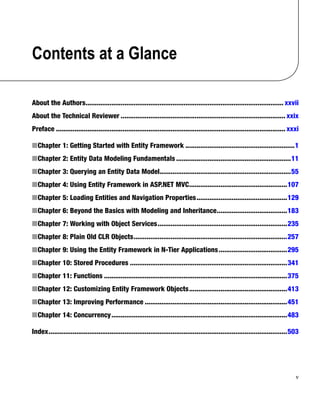
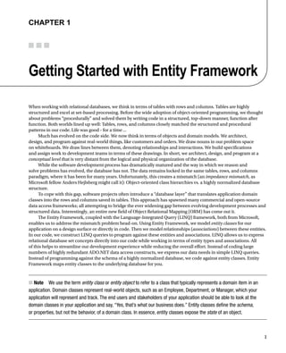
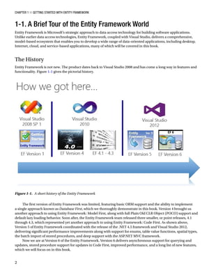
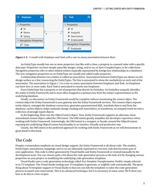
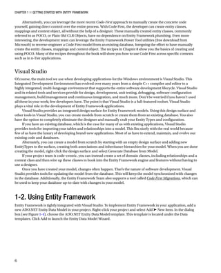


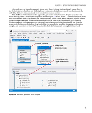

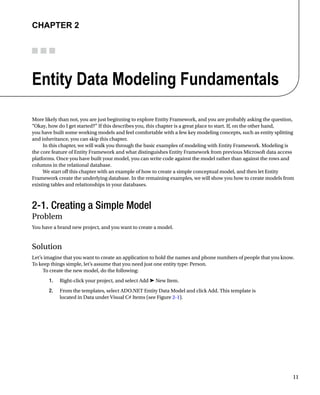
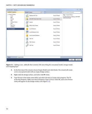
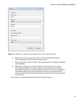
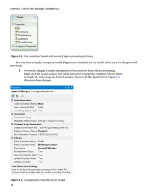

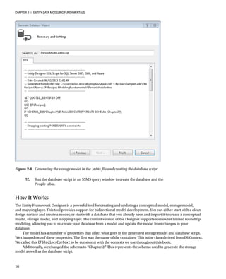
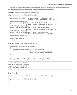
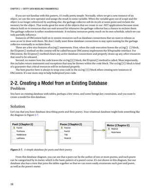
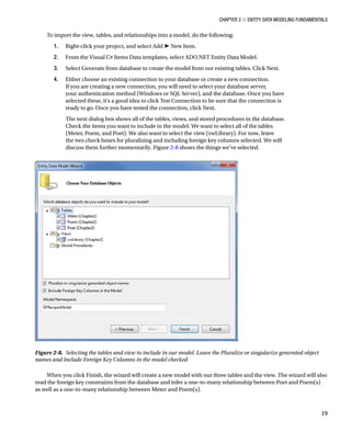
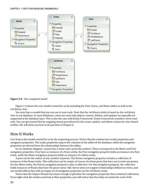
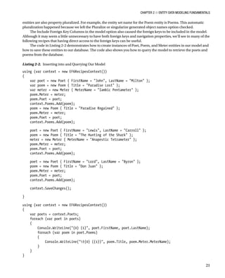
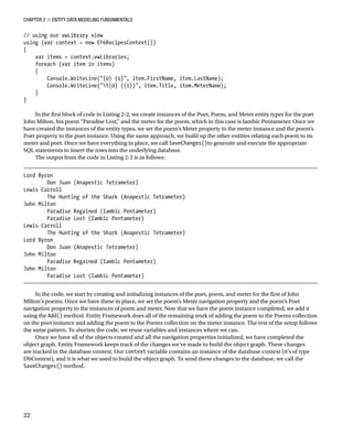
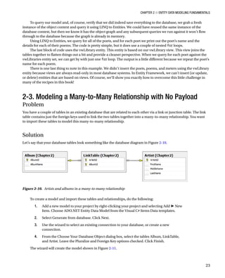
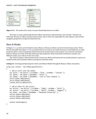
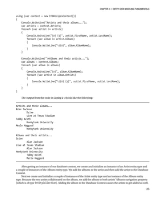
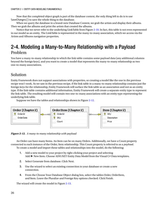
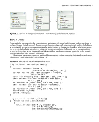
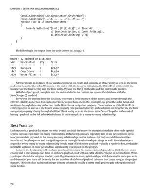
![Chapter 2 ■ Entity Data Modeling Fundamentals
29
2-5. Modeling a Self-Referencing Relationship with
a Code-First Approach
Problem
You have a table that references itself, and you want to model this as an entity with a self-referencing association using
a Code-First approach.
Solution
Let’s say that you have a self-referencing table that’s like the one shown in the database diagram in Figure 2-14.
To create a model and import this table and the self-referencing relationship into the model, do the following:
1. Create a new class that inherits from DbContext in your project.
2. Use the code in Listing 2-5 to create the PictureCategory POCO entity.
Listing 2-5. Creating the PictureCategory POCO Entity
public class PictureCategory
{
[Key]
[DatabaseGenerated(DatabaseGeneratedOption.Identity)]
public int CategoryId { get; private set; }
public string Name { get; set; }
public int? ParentCategoryId { get; private set; }
[ForeignKey(ParentCategoryId)]
public PictureCategory ParentCategory { get; set; }
public ListPictureCategory Subcategories { get; set; }
public PictureCategory()
{
Subcategories = new ListPictureCategory();
}
}
Figure 2-14. A self-referencing table](https://image.slidesharecdn.com/16284-250619131605-7268a16b/85/Entity-Framework-6-Recipes-2nd-Edition-Brian-Driscoll-35-320.jpg)
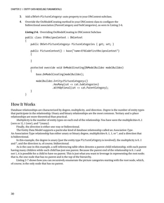
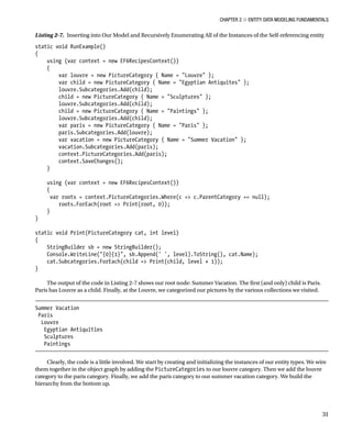
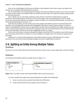
![Chapter 2 ■ Entity Data Modeling Fundamentals
33
Listing 2-8. Creating the Product POCO Entity
public class Product
{
[Key]
[DatabaseGenerated(DatabaseGeneratedOption.None)]
public int SKU { get; set; }
public string Description { get; set; }
public decimal Price { get; set; }
public string ImageURL { get; set; }
}
3. Add an auto-property of type DbSetProduct to your DbContext subclass.
4. Override the OnModelCreating() method of DbContext with the code in Listing 2-9.
Listing 2-9. Overriding OnModelCreating in the DbContext Subclass
public class EF6RecipesContext : DbContext
{
public DbSetProduct Products { get; set; }
public ProductContext() : base(name=EF6CodeFirstRecipesContext)
{
}
protected override void OnModelCreating(DbModelBuilder modelBuilder)
{
base.OnModelCreating(modelBuilder);
modelBuilder.EntityProduct()
.Map(m =
{
m.Properties(p = new {p.SKU, p.Description, p.Price});
m.ToTable(Product, Chapter2);
})
.Map(m =
{
m.Properties(p = new {p.SKU, p.ImageURL});
m.ToTable(ProductWebInfo, Chapter2);
});
}
}
How It Works
It seems all too common in legacy systems to find “extra” information for each row in one table tucked away in
another table. Often this happens over time as a database evolves, and no one is willing to break existing code by
adding columns to some critical table. The answer is to “graft on” a new table to hold the additional columns.
By merging two or more tables into a single entity or, as it is usually perceived, splitting a single entity across two
or more tables, we can treat all of the parts as one logical entity. This process is often referred to as vertical splitting.](https://image.slidesharecdn.com/16284-250619131605-7268a16b/85/Entity-Framework-6-Recipes-2nd-Edition-Brian-Driscoll-39-320.jpg)
![Chapter 2 ■ Entity Data Modeling Fundamentals
34
The downside of vertical splitting is that retrieving each instance of our entity now requires an additional join for
each additional table that makes up the entity type. This extra join is shown in Listing 2-10.
Listing 2-10. Additional Join Required by Vertical Splitting
SELECT
[Extent1].[SKU] AS [SKU],
[Extent2].[Description] AS [Description],
[Extent2].[Price] AS [Price],
[Extent1].[ImageURL] AS [ImageURL]
FROM [dbo].[ProductWebInfo] AS [Extent1]
INNER JOIN [dbo].[Product] AS [Extent2] ON [Extent1].[SKU] = [Extent2].[SKU]
Nothing special is required to insert into or retrieve from the Product entity. Listing 2-11 demonstrates working
with the vertically split Product entity type.
Listing 2-11. Inserting into and Retrieving from Our Model with the Product Entity Type
using (var context = new EF6RecipesContext())
{
var product = new Product { SKU = 147,
Description = Expandable Hydration Pack,
Price = 19.97M, ImageURL = /pack147.jpg };
context.Products.Add(product);
product = new Product { SKU = 178,
Description = Rugged Ranger Duffel Bag,
Price = 39.97M, ImageURL = /pack178.jpg };
context.Products.Add(product);
product = new Product { SKU = 186,
Description = Range Field Pack,
Price = 98.97M, ImageURL = /noimage.jp };
context.Products.Add(product);
product = new Product { SKU = 202,
Description = Small Deployment Back Pack,
Price = 29.97M, ImageURL = /pack202.jpg };
context.Products.Add(product);
context.SaveChanges();
}
using (var context = new EF6RecipesContext())
{
foreach (var p in context.Products)
{
Console.WriteLine({0} {1} {2} {3}, p.SKU, p.Description,
p.Price.ToString(C), p.ImageURL);
}
}](https://image.slidesharecdn.com/16284-250619131605-7268a16b/85/Entity-Framework-6-Recipes-2nd-Edition-Brian-Driscoll-40-320.jpg)
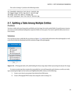
![Chapter 2 ■ Entity Data Modeling Fundamentals
36
Listing 2-12. Creating the Photograph POCO Entity
public class Photograph
{
[Key]
[DatabaseGenerated(DatabaseGeneratedOption.Identity)]
public int PhotoId { get; set; }
public string Title { get; set; }
public byte[] ThumbnailBits { get; set; }
[ForeignKey(PhotoId)]
public virtual PhotographFullImage PhotographFullImage { get; set; }
}
3. Create a PhotographFullImage POCO entity class using the code in Listing 2-13.
Listing 2-13. Creating the PhotographFullImage POCO Entity
public class PhotographFullImage
{
[Key]
public int PhotoId { get; set; }
public byte[] HighResolutionBits { get; set; }
[ForeignKey(PhotoId)]
public virtual Photograph Photograph { get; set; }
}
4. Add an auto-property of type DbSetPhotograph to your DbContext subclass.
5. Add another auto-property type of DbSetPhotographFullImage to your DbContext
subclass.
6. Override the OnModelCreating() method of the DbContext class, as shown in Listing 2-14.
Listing 2-14. Overriding the OnModelCreating Method of DbContext
protected override void OnModelCreating(DbModelBuilder modelBuilder)
{
base.OnModelCreating(modelBuilder);
modelBuilder.EntityPhotograph()
.HasRequired(p = p.PhotographFullImage)
.WithRequiredPrincipal(p = p.Photograph);
modelBuilder.EntityPhotograph().ToTable(Photograph, Chapter2);
modelBuilder.EntityPhotographFullImage().ToTable(Photograph, Chapter2);
}](https://image.slidesharecdn.com/16284-250619131605-7268a16b/85/Entity-Framework-6-Recipes-2nd-Edition-Brian-Driscoll-42-320.jpg)
![Chapter 2 ■ Entity Data Modeling Fundamentals
37
How It Works
Entity Framework does not directly support the notion of lazy loading of individual entity properties. To get the effect
of lazy loading expensive properties, we exploit Entity Framework’s support for lazy loading of associated entities.
We created a new entity type to hold the expensive full image property and created a one-to-one association between
our Photograph entity type and the new PhotographFullImage entity type. We added a referential constraint on the
conceptual layer that, much like a database referential constraint, tells Entity Framework that a PhotographFullImage
can’t exist without a Photograph.
Due to the referential constraint, there are a couple of things to note about our model. If we have a newly created
PhotographFullImage, an instance of Photograph must exist in the object context or the data source prior to calling
SaveChanges(). Also, if we delete a photograph, the associated PhotographFullImage is also deleted. This is just like
cascading deletes in database referential constraints.
The code in Listing 2-15 demonstrates inserting and retrieving from our model.
Listing 2-15. Inserting into and Lazy Loading Expensive Fields
byte[] thumbBits = new byte[100];
byte[] fullBits = new byte[2000];
using (var context = new EF6RecipesContext())
{
var photo = new Photograph { Title = My Dog,
ThumbnailBits = thumbBits };
var fullImage = new PhotographFullImage { HighResolutionBits = fullBits };
photo.PhotographFullImage = fullImage;
context.Photographs.Add(photo);
context.SaveChanges();
}
using (var context = new EF6RecipesContext())
{
foreach (var photo in context.Photographs)
{
Console.WriteLine(Photo: {0}, ThumbnailSize {1} bytes,
photo.Title, photo.ThumbnailBits.Length);
// explicitly load the expensive entity,
PhotographFullImagecontext.Entry(photo).Reference(p = p.PhotographFullImage).Load();
Console.WriteLine(Full Image Size: {0} bytes,
photo.PhotographFullImage.HighResolutionBits.Length);
}
}
The output from Listing 2-15 is as follows:
Photo: My Dog, Thumbnail Size: 100 bytes
Full Image Size: 2000 bytes
The code in Listing 2-15 creates and initializes instances of the Photograph and PhotographFullImage entities,
adds them to the object context, and calls SaveChanges().](https://image.slidesharecdn.com/16284-250619131605-7268a16b/85/Entity-Framework-6-Recipes-2nd-Edition-Brian-Driscoll-43-320.jpg)
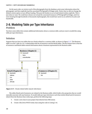
![Chapter 2 ■ Entity Data Modeling Fundamentals
39
Listing 2-16. Creating the Business POCO Entity Class
[Table(Business, Schema = Chapter2)]
public class Business
{
[Key]
[DatabaseGenerated(DatabaseGeneratedOption.Identity)]
public int BusinessId { get; protected set; }
public string Name { get; set; }
public string LicenseNumber { get; set; }
}
3. Create an eCommerce POCO entity class that inherits from the Business class using the
code in Listing 2-17.
Listing 2-17. Creating the eCommerce POCO Entity Class
[Table(eCommerce, Schema = Chapter2)]
public class eCommerce : Business
{
public string URL { get; set; }
}
4. Create a Retail POCO entity class that inherits from the Business class using the code
in Listing 2-18.
Listing 2-18. Creating the Retail POCO Entity Class
[Table(Retail, Schema = Chapter2)]
public class Retail : Business
{
public string Address { get; set; }
public string City { get; set; }
public string State { get; set; }
public string ZIPCode { get; set; }
}
5. Add an auto-property of type DbSetBusiness to your DbContext subclass.
How It Works
Both the Retail and the eCommerce tables are on the 0..1 side of a 1:0..1 relationship with the Business table.
This means that we could have a business with no additional information or a business with additional Retail or
eCommerce information. In object-oriented programming terms, we have a base type, Business, with two derived
types, Retail and eCommerce.
Because of the 1:0..1 relationship, we cannot have a row in the Retail or eCommerce tables without a
corresponding row in the Business table. In object-oriented terms, an instance of a derived type has the properties
of the base type. This concept of a derived type extending the properties of a base type is a key feature of inheritance.
In table per type (often abbreviated TPT) inheritance, each of the derived types is represented in separate tables.](https://image.slidesharecdn.com/16284-250619131605-7268a16b/85/Entity-Framework-6-Recipes-2nd-Edition-Brian-Driscoll-45-320.jpg)

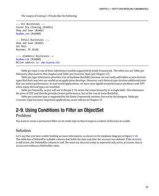
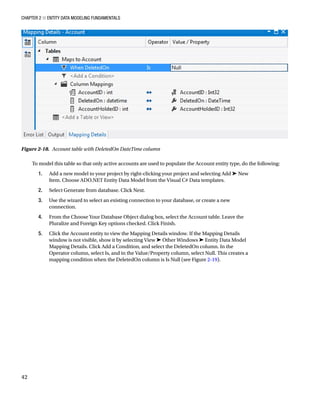

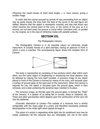

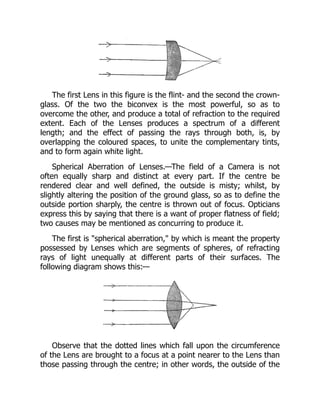
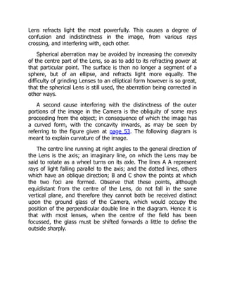
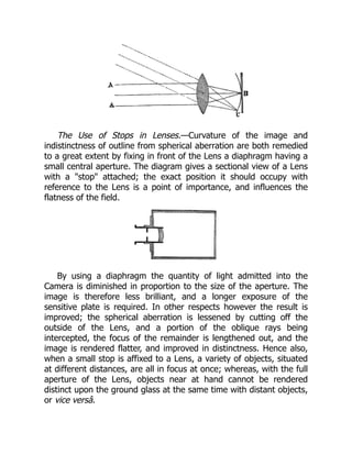
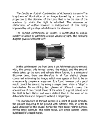
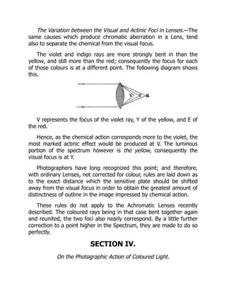
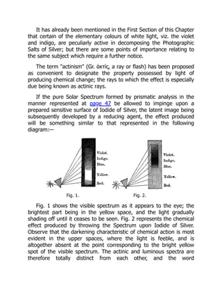
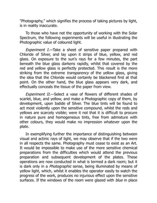

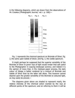
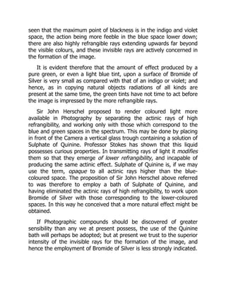
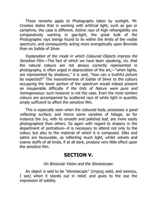
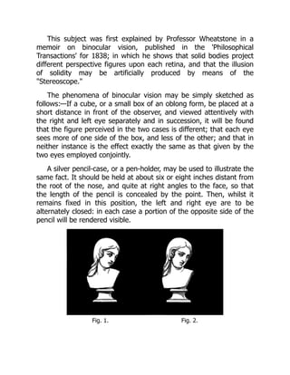
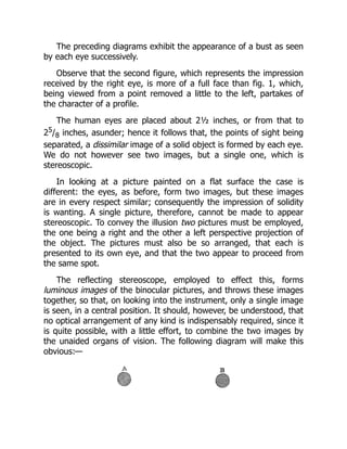
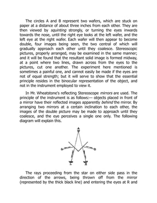
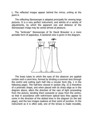
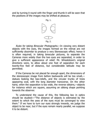
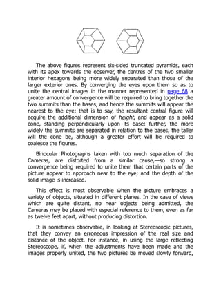
![the eyes remaining fixed upon the mirrors, the Stereoscopic image
will gradually change its character, the various objects it embraces
appearing to become diminished in size, and approaching near to
the observer: whilst if the pictures be pushed backwards, the image
will enlarge and recede to a distance. So, again, if an ordinary slide
for the lenticular Stereoscope be divided in the centre, and, looking
into the instrument until the images coalesce, the two halves be
slowly separated from each other, the solid picture will seem to
become larger and to recede from the eye.
It is easy to understand the cause of this. When the pictures in
the reflecting Stereoscope are moved forwards, the convergence of
the optic axes is increased: the image therefore appears nearer, in
accordance with the last-mentioned law. But to convey the
impression of nearness is equivalent to an apparent diminution in
size, for we judge of the dimensions of a body very much in relation
to its supposed distance. Of two figures, for instance, appearing of
the same height, one known to be a hundred yards off might be
considered colossal, whilst the other, obviously near at hand, would
be viewed as a statuette.
These facts, with others not mentioned, are of great interest and
importance, but their further consideration does not fall within the
bounds originally prescribed to us. The practical details of
Stereoscopic Photography have been arranged in a distinct Section,
and will be found included in the Second Part of the Work.[11]
[11] For a more full and detailed explanation of the
Stereoscopic phenomena, see an abstract of Professor Tyndall's
lectures in the third volume of the 'Photographic Journal.'](https://image.slidesharecdn.com/16284-250619131605-7268a16b/85/Entity-Framework-6-Recipes-2nd-Edition-Brian-Driscoll-69-320.jpg)
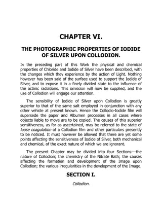
![Collodion (so named from the Greek word κολλἁω, to stick) is a
glutinous, transparent fluid, procured, as generally said, by
dissolving Gun-Cotton in Ether. It was originally used for surgical
purposes only, being smeared over wounds and raw surfaces, to
preserve them from contact with the air by the tough film which it
leaves on evaporation. Photographers employ it to support a delicate
film of Iodide of Silver upon the surface of a smooth glass plate.
Two elements enter into the composition of Collodion: first, the
Gun-Cotton; second, the fluids used to dissolve it. Each of these will
be treated in succession.
CHEMISTRY OF PYROXYLINE.
Gun-Cotton or Pyroxyline is Cotton or Paper which has been
altered in composition and properties by treatment with strong
acids.
Both Cotton and Paper are, chemically, the same. They consist of
fibres which are found on analysis to have a constant composition,
containing three elementary bodies, Carbon, Hydrogen, and Oxygen,
united together in fixed proportions. To this combination the term
Lignine or Cellulose[12] has been applied.
[12] Lignine and Cellulose are not precisely identical
substances. The latter is the material composing the cell-wall; the
former, the contained matter in the cell.
Cellulose is a definite chemical compound, in the same sense as
Starch or Sugar, and consequently, when treated with various
reagents, it exhibits properties peculiar to itself. It is insoluble in
most liquids, such as Water, Alcohol, Ether, etc., and also in dilute
acids; but when acted upon by Nitric Acid of a certain strength it
liquefies and dissolves.
It has been already shown (p. 12) that when a body dissolves in
Nitric Acid the solution is not usually of the same nature as an](https://image.slidesharecdn.com/16284-250619131605-7268a16b/85/Entity-Framework-6-Recipes-2nd-Edition-Brian-Driscoll-71-320.jpg)
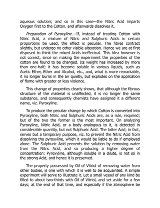
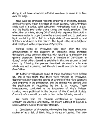
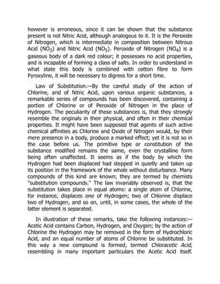

![of Vitriol is more to be depended upon, and has a tolerably uniform
Sp. Gr. of 1·836;[13] but Nitric Acid is constantly liable to variation;
hence it becomes necessary to make a preliminary determination of
its real strength, which is done either by taking the specific gravity
and referring to tables, or, better still, by a direct analysis. As each
atom of Sulphuric Acid removes only a given quantity of water, it
follows that the weaker the Nitric Acid, the larger the amount of
Sulphuric which will be required to bring it up to the proper degree
of concentration.
[13] The later experience of the writer induces him to believe,
that the specific gravity of Oil of Vitriol cannot always be taken as
an indication of its real strength; which is best ascertained by
analysis.
To avoid the trouble necessarily attendant upon these preliminary
operations, many prefer to use, in place of Nitric Acid itself, one of
the salts formed by the combination of Nitric Acid with an alkaline
base. The composition of these salts, provided they are pure and
nicely crystallized, can be depended on.
Nitrate of Potash, or Saltpetre, contains a single atom of Nitric
Acid united with one of Potash. It is an anhydrous salt, that is, it has
no water of crystallization. When strong Sulphuric Acid is poured
upon Nitrate of Potash in a state of fine powder, in virtue of its
superior chemical affinities it appropriates to itself the Alkali and
liberates the Nitric Acid. If care be taken to add a sufficient excess of
the Sulphuric Acid, a solution is obtained containing Sulphate of
Potash dissolved in Sulphuric Acid, and free Nitric Acid. The presence
of the Sulphate of Potash (or, more strictly speaking, of the Bi-
Sulphate) does not in any way interfere with the result, and the
effect is the same as if the mixed acids themselves had been used.
The reaction may be thus represented:—
Nitrate of Potash plusSulphuric Acid in excess
=Bisulphate PotashplusNitro-Sulphuric Acid.](https://image.slidesharecdn.com/16284-250619131605-7268a16b/85/Entity-Framework-6-Recipes-2nd-Edition-Brian-Driscoll-77-320.jpg)