Joshua Grosserhode's engineering portfolio document contains summaries of several projects he worked on as an undergraduate student at Oregon State University studying mechanical engineering. The projects included designing an autonomously guided glider payload that was ejected from a 30,000 foot sounding rocket, building a paper launcher for a competition to launch paper balls into a target, and participating twice in a 30 hour engineering challenge where he helped build a remote control car and an automated sidewalk chalk marker. The document provides details on his responsibilities and contributions to each project.

![2
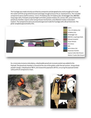
Two recoverysystems were used,aprimaryanda secondary.The primaryrecoverysystem wasthe wing
and tail whichslowedthe descentandguidedittothe landingside.The secondaryrecoverysystem was
a deployable parachute that furtherslowedthe descentonce the payloadwas ata loweraltitude.Both
recoverysystems were entirelystudentdesigned,manufacturedandtested.
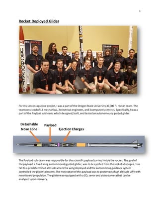
Stored/Free Fall Configuration FlightConfiguration
A carbon fiberloadstiffenedwingwasused asthe primaryliftingbodyforthe glider.A loadstiffened
wingcapable of beingrolledunderpressure andautomaticallystiffenedintoaflightconfigurationwhen
released.The wing wasmade outthree pliesof T-800 carbon fiberweave witha[45°/-45°/45°] layup
schedule,allowingittoroll and be placedintothe rockettube.
The tail sectionof the payloadwasdesignedto give the glidercontrol authority andstability duringits
flight,whilestillbeingcapable of fittinginsideof the rocket.Originallyatraditiontail designwas
selectedforsimplicitybutthisresultedinalackof surface areaneededtoproperlycontrol the glider.
The solution wasto use an invertedV-tail. Withthe V-tail,itwaspossible fitamuchlargercontrol area
inside the rocket,since the tail canroll similarlytothe wing. Additionally, the inverted“V”designonly
had twocontrol surfacesreducingthe numberof requiredcomponents.](https://image.slidesharecdn.com/portfolio-170907163155/85/Engineering-Portfolio-4-320.jpg)